JP2015104789A - Robot - Google Patents
Robot Download PDFInfo
- Publication number
- JP2015104789A JP2015104789A JP2013248935A JP2013248935A JP2015104789A JP 2015104789 A JP2015104789 A JP 2015104789A JP 2013248935 A JP2013248935 A JP 2013248935A JP 2013248935 A JP2013248935 A JP 2013248935A JP 2015104789 A JP2015104789 A JP 2015104789A
- Authority
- JP
- Japan
- Prior art keywords
- joint
- arm
- angular velocity
- robot
- sensor
- Prior art date
- Legal status (The legal status is an assumption and is not a legal conclusion. Google has not performed a legal analysis and makes no representation as to the accuracy of the status listed.)
- Pending
Links
Images


Abstract
Description
本発明は、ロボットに関する。 The present invention relates to a robot.
複数のアーム部材を関節で接続したアームを有するロボットが知られている。このロボットは、アームの先端にロボットハンドなどを取り付けることによって様々な作業を行うことができる。もっとも、作業を行うために、アームの先端のロボットハンドなどを目的の位置に移動させて停止させても、暫くの間はアームの先端が振動するので作業を開始することができない。 A robot having an arm in which a plurality of arm members are connected by joints is known. This robot can perform various operations by attaching a robot hand or the like to the tip of the arm. However, even if the robot hand or the like at the tip of the arm is moved to a target position and stopped to perform the work, the work cannot be started because the tip of the arm vibrates for a while.
そこで、アームの先端側に慣性センサーを搭載しておき、慣性センサーの出力が小さくなるように、アームの各関節の動きを制御することで、アームの振動を抑制する技術が提案されている(特許文献1)。 Therefore, a technique has been proposed in which an inertial sensor is mounted on the distal end side of the arm, and the arm vibration is controlled by controlling the movement of each joint of the arm so that the output of the inertial sensor is reduced ( Patent Document 1).
しかし、多くの関節を備えるロボットの中には、ある関節を動かすことによって、それより先の関節の回転軸の向きが変化するようなロボットも存在しており、このロボットについては、上記の提案されている技術を適用しても、アームの振動を十分に抑制することが難しいという問題があった。これは、アームの先端が同じように振動している場合でも、例えばアームの先端側の関節についての制御内容(制御量および制御方向)は、それより根元側の関節の回転位置によって変わってしまうので、制御が複雑になるためである。また、アームの先端が振動している場合、通常は根元側の関節でも振動が発生して回転位置が刻々と変化し、その結果、先端側の関節の向きが刻々と変化するので、より一層制御が複雑になる。加えて、関節の変形や機械誤差による影響は先端になるほど蓄積する。このため、上述した課題を有するロボットに上記の提案の技術を適用すると、却って振動が増幅される場合もあった。このように、回転軸の方向が異なる複数の関節を有するロボットの振動を抑制するには多くの課題が残されていた。 However, among robots with many joints, there are robots that change the direction of the rotation axis of a joint ahead of them by moving a certain joint. Even if the applied technology is applied, there is a problem that it is difficult to sufficiently suppress the vibration of the arm. This is because even when the tip of the arm vibrates in the same manner, for example, the control content (control amount and control direction) of the joint on the tip side of the arm changes depending on the rotational position of the joint on the base side. This is because the control becomes complicated. In addition, when the tip of the arm vibrates, vibration is also generated in the joint on the base side and the rotational position changes every moment, and as a result, the direction of the joint on the tip side changes every moment. Control is complicated. In addition, the effects of joint deformation and mechanical errors accumulate as the tip approaches. For this reason, when the proposed technique is applied to a robot having the above-described problems, vibration may be amplified. As described above, many problems remain to suppress vibration of a robot having a plurality of joints having different directions of the rotation axis.
この発明は、従来の技術が有する上述した課題を解決するためになされたものであり、ロボットのアームの振動を抑制することが可能な技術の提供を目的とする。 The present invention has been made in order to solve the above-described problems of the prior art, and an object of the present invention is to provide a technique capable of suppressing vibration of a robot arm.
上述した課題の少なくとも一部を解決するために、本発明のロボットは次の構成を採用した。すなわち、
第1関節および前記第1関節とは回転方向が異なる方向である第2関節を含む複数の関節と、基台に対して前記第1関節を介して回転可能に設けられた第1アーム部材を含む複数のアーム部材と、
前記第1アーム部材または前記第1関節に設けられた第1角速度センサーと、
を備えることを特徴とする。
In order to solve at least a part of the problems described above, the robot of the present invention employs the following configuration. That is,
A plurality of joints including a second joint having a rotation direction different from that of the first joint and the first joint; and a first arm member provided rotatably with respect to a base via the first joint Including a plurality of arm members;
A first angular velocity sensor provided on the first arm member or the first joint;
It is characterized by providing.
こうすれば、第1角速度センサーの出力から、第1関節を介して基台に取り付けられた第1アーム部材の動きを検出することができる。このため、第1アーム部材と基台との間の第1関節の動きが、その他の複数の関節の動きに与える影響を考慮して、他の関節を制御することができるので、ロボットのアームの振動を抑制することが可能となる。また、第1角速度センサーの出力に基づいて第1関節の動きを検出することができるので、アームの先端側に向かって誤差の影響が蓄積することも抑制することが可能となる。このため、各関節を制御することでアームの振動が増幅される虞も抑制することが可能となる。 If it carries out like this, the motion of the 1st arm member attached to the base via the 1st joint can be detected from the output of the 1st angular velocity sensor. Therefore, it is possible to control the other joints in consideration of the influence of the movement of the first joint between the first arm member and the base on the movements of the other plurality of joints. Can be suppressed. Further, since the movement of the first joint can be detected based on the output of the first angular velocity sensor, it is possible to suppress the accumulation of the influence of the error toward the distal end side of the arm. For this reason, it is possible to suppress the possibility that the vibration of the arm is amplified by controlling each joint.
また、上述した本発明のロボットにおいては、複数のアーム部材の中で第1アーム部材とは異なるアーム部材に第2角速度センサーを設けてもよい。 In the robot of the present invention described above, the second angular velocity sensor may be provided on an arm member different from the first arm member among the plurality of arm members.
こうすれば、第1角速度センサーの出力に加えて、第2角速度センサーの出力も用いて制御することができるので、アームの振動をより一層抑制することが可能となる。また、一軸の出力を用いることとすれば、制御のための演算量が小さくなるので、アームの振動をより一層抑制することが可能となる。 By doing so, in addition to the output of the first angular velocity sensor, it is possible to control using the output of the second angular velocity sensor, so it is possible to further suppress the vibration of the arm. Further, if a uniaxial output is used, the amount of calculation for control becomes small, so that the vibration of the arm can be further suppressed.
また、上述した本発明のロボットにおいては、第2角速度センサーの出力に基づいて、第2角速度センサーが設けられたアーム部材よりも、基台側の関節をフィードバック制御する制御部を備えるようにしてもよい。 Further, the robot of the present invention described above includes a control unit that feedback-controls the joint on the base side rather than the arm member provided with the second angular velocity sensor, based on the output of the second angular velocity sensor. Also good.
第2角速度センサーの出力には、第2角速度センサーが設けられたアーム部材の動きだけでなく、そのアーム部材よりも基台側の関節の動きが現れる。従って、第2角速度センサーの出力に基づいて基台側の関節をフィードバック制御してやれば、アームの振動をより一層抑制することが可能となる。また、振動が大きい基台側の関節を制御することができるので、アームの振動をより効果的に抑制することが可能となる。 In the output of the second angular velocity sensor, not only the movement of the arm member provided with the second angular velocity sensor but also the movement of the joint on the base side with respect to the arm member appears. Therefore, if the joint on the base side is feedback-controlled based on the output of the second angular velocity sensor, the vibration of the arm can be further suppressed. In addition, since the joint on the base side where the vibration is large can be controlled, the vibration of the arm can be more effectively suppressed.
また、上述した本発明のロボットにおいては、第2角速度センサーが設けられたアーム部材の基台側の関節と回転軸の方向が一致する関節を、第2角速度センサーの出力に基づいてフィードバック制御することとしてもよい。尚、「回転軸の方向が一致する」とは、完全な一致に限らず、実質上一致していればよい。従って、回転軸の方向が±5°の範囲で異なっている場合は、本明細書でいうところの「回転軸の方向が一致する」場合に該当する。 In the robot of the present invention described above, feedback control is performed based on the output of the second angular velocity sensor for the joint on the base side of the arm member on which the second angular velocity sensor is provided and the direction of the rotation axis coincides. It is good as well. Note that “the directions of the rotation axes match” is not limited to a perfect match, but may be a match. Therefore, the case where the directions of the rotation axes are different within a range of ± 5 ° corresponds to the case where “the directions of the rotation axes coincide” in this specification.
第2角速度センサーの出力には、当然ながら、その第2角速度センサーが設けられたアーム部材の基台側の関節の動きが反映される。しかし、その関節に加えて、回転軸の方向が一致する関節がより基台側にも存在する場合には、その基台側の関節(第2角速度センサーが設けられたアーム部材の基台側の関節と回転軸の方向が一致する関節)の動きも、第2角速度センサーの出力に反映される。しかも、その基台側の関節の動きが増幅されて反映される。従って、第2角速度センサーが設けられたアーム部材の基台側の関節と回転軸の方向が一致する関節を、第2角速度センサーの出力に基づいてフィードバック制御してやれば、第2角速度センサーが設けられたアーム部材の関節以外の関節も精度良く制御することができるので、アームの振動を抑制することが可能となる。また、振動が大きい基台側の関節を制御することができるので、アームの振動をより効果的に抑制することが可能となる。 Naturally, the output of the second angular velocity sensor reflects the movement of the joint on the base side of the arm member provided with the second angular velocity sensor. However, in addition to the joint, if there is a joint with the same rotational axis direction on the base side, the base side joint (the base side of the arm member provided with the second angular velocity sensor) The motion of the joint and the direction of the rotation axis are also reflected in the output of the second angular velocity sensor. Moreover, the movement of the joint on the base side is amplified and reflected. Therefore, the second angular velocity sensor is provided if the joint on the base side of the arm member provided with the second angular velocity sensor and the joint having the same rotational axis direction are feedback-controlled based on the output of the second angular velocity sensor. Since the joints other than the joints of the arm members can be controlled with high accuracy, the arm vibration can be suppressed. In addition, since the joint on the base side where the vibration is large can be controlled, the vibration of the arm can be more effectively suppressed.
また、本発明のロボットは、次のような態様で把握することもできる。すなわち、
第1関節および前記第1関節とは回転方向が異なる方向である第2関節を含む複数の関節と、
前記複数の関節によって連結された複数のアーム部材と、
前記複数のアーム部材の中の1の前記アーム部材に設けられた第1角速度センサーと、
前記第1角速度センサーが設けられた前記アーム部材とは異なる前記アーム部材に設けられた第2角速度センサーと、
を備えることを特徴とするロボットとして把握することもできる。
The robot of the present invention can be grasped in the following manner. That is,
A plurality of joints including a first joint and a second joint having a rotation direction different from the first joint;
A plurality of arm members connected by the plurality of joints;
A first angular velocity sensor provided on one of the plurality of arm members;
A second angular velocity sensor provided on the arm member different from the arm member provided with the first angular velocity sensor;
It can also be grasped as a robot characterized by having
このような本発明のロボットにおいては、第1角速度センサーおよび第2角速度センサーの出力に基づいて複数の関節を制御することができるので、ロボットのアームの振動を速やかに抑制することが可能となる。また、こうすれば、アームの振動を速やかに抑制することができるので、たとえアームの剛性(アーム部材や関節の剛性)が低い場合でも、アームの振動を抑制することが可能となる。 In such a robot of the present invention, a plurality of joints can be controlled based on the outputs of the first angular velocity sensor and the second angular velocity sensor, so that vibration of the robot arm can be quickly suppressed. . In addition, since the vibration of the arm can be suppressed promptly in this way, it is possible to suppress the vibration of the arm even when the rigidity of the arm (the rigidity of the arm member or joint) is low.
また、上述した本発明のロボットにおいては、第1角速度センサーの一軸の出力および第2角速度センサーの一軸の出力に基づいて、複数の関節を制御する制御部を備えることとしてもよい。 The robot of the present invention described above may include a control unit that controls a plurality of joints based on the output of one axis of the first angular velocity sensor and the output of one axis of the second angular velocity sensor.
こうすれば、複数の角速度センサーを用いた場合でも、単純な制御でロボットのアームの振動を抑制することが可能となる。また、一軸の出力を用いることで演算量が抑制されるので、高速な制御を行うことができ、アームの振動を抑制することが可能となる。 In this way, even when a plurality of angular velocity sensors are used, vibration of the robot arm can be suppressed with simple control. In addition, since the amount of calculation is suppressed by using the output of one axis, it is possible to perform high-speed control and suppress arm vibration.
また、上述した本発明のロボットにおいては、第1角速度センサーの一軸の出力および第2角速度センサーの三軸の出力に基づいて、複数の関節を制御することとしてもよい。 In the robot of the present invention described above, a plurality of joints may be controlled based on the output of one axis of the first angular velocity sensor and the output of three axes of the second angular velocity sensor.
ある関節の回転軸の向きが他の関節の動きによって変化する場合でも、関節の回転軸の向きが変化するアーム部材には三軸の出力を使用する第2角速度センサーを取り付けておけば、複数の関節を制御してアームの振動を抑制することが可能となる。また、第1角速度センサーについては一軸の出力を使用することで演算量を抑制し、第2角速度センサーについては三軸の出力を使用することで制御の精度を確保することができる。その結果、アームの振動をより一層抑制することが可能となる。 Even if the direction of the rotation axis of a joint changes due to the movement of another joint, if the second angular velocity sensor that uses a triaxial output is attached to the arm member that changes the direction of the rotation axis of the joint, multiple It is possible to suppress the vibration of the arm by controlling the joint. In addition, the calculation amount can be suppressed by using a uniaxial output for the first angular velocity sensor, and the control accuracy can be ensured by using a triaxial output for the second angular velocity sensor. As a result, it is possible to further suppress the vibration of the arm.
また、上述した本発明のロボットにおいては、第1角速度センサーおよび第2角速度センサーの出力に基づいて、次のようにして複数の関節をフィードバック制御してもよい。先ず、第1角速度センサーの出力に基づいて、第1角速度センサーが設けられたアーム部材よりも基台側の関節をフィードバック制御する。且つ、第2角速度センサーの出力に基づいて、第2角速度センサーが設けられたアーム部材よりも基台側の関節をフィードバック制御する。 In the robot of the present invention described above, a plurality of joints may be feedback-controlled as follows based on the outputs of the first angular velocity sensor and the second angular velocity sensor. First, based on the output of the first angular velocity sensor, feedback control is performed on the joint on the base side with respect to the arm member provided with the first angular velocity sensor. In addition, based on the output of the second angular velocity sensor, feedback control is performed on the joint on the base side with respect to the arm member provided with the second angular velocity sensor.
関節の動きは、その関節よりも、基台から見て遠くの位置に角速度センサーを設けることで、より感度良く検出することができる。従って、第1角速度センサーの出力および第2角速度センサーの出力に基づいて、上述した方法で関節をフィードバック制御してやれば、精度良く制御することが可能となり、アームの振動を抑制することが可能となる。 The movement of the joint can be detected with higher sensitivity by providing an angular velocity sensor at a position farther from the base than the joint. Therefore, if the joint is feedback-controlled by the above-described method based on the output of the first angular velocity sensor and the output of the second angular velocity sensor, the joint can be controlled with high accuracy and the vibration of the arm can be suppressed. .
また、上述した本発明のロボットにおいては、第1角速度センサーの出力に基づいてフィードバック制御される関節と、第2角速度センサーの出力に基づいてフィードバック制御される関節とは、回転軸が直交している関節としても良い。 In the robot of the present invention described above, the rotation axis of the joint that is feedback-controlled based on the output of the first angular velocity sensor and the joint that is feedback-controlled based on the output of the second angular velocity sensor are orthogonal to each other. It is good as a joint.
回転軸が直交する関節は、それぞれ独立に制御することができるので、簡単に且つ精度良く制御することができる。その結果、アームに存在する複数の関節の動きを、簡単に且つ精度良く制御してアームの振動を抑制することが可能となる。 Since the joints whose rotation axes are orthogonal to each other can be controlled independently, they can be controlled easily and accurately. As a result, it is possible to control the movements of a plurality of joints existing in the arm easily and accurately to suppress arm vibration.
また、上述した本発明のロボットにおいては、両側の関節の回転軸が互いに異なるアーム部材の中で基台に最も近いアーム部材に、第1角速度センサーを設けることとしてもよい。 In the robot of the present invention described above, the first angular velocity sensor may be provided on the arm member closest to the base among the arm members having different rotation axes of the joints on both sides.
こうすれば、複数の関節の動きを、簡単に且つ精度良く制御することができるので、アームの振動を抑制することが可能となる。 By doing so, the movements of the plurality of joints can be controlled easily and accurately, so that the vibration of the arm can be suppressed.
また、上述した本発明のロボットにおいては、第1角速度センサーとして振動型ジャイロセンサーを用いても良い。 In the robot of the present invention described above, a vibration gyro sensor may be used as the first angular velocity sensor.
振動型ジャイロセンサーは、他の方式のジャイロセンサーに比べて小型化できるので、ロボットを小型化することが可能となる。 Since the vibration type gyro sensor can be downsized as compared with other types of gyro sensors, the robot can be downsized.
また、第1角速度センサーとして振動型ジャイロセンサーを用いる本発明のロボットにおいては、圧電材料を含んだ振動型ジャイロセンサーを、第1角速度センサーとして用いても良い。 Further, in the robot of the present invention using the vibration gyro sensor as the first angular velocity sensor, a vibration gyro sensor including a piezoelectric material may be used as the first angular velocity sensor.
振動型ジャイロセンサーの中でも、圧電材料を含む振動型ジャイロセンサー(いわゆる圧電方式の振動型ジャイロセンサー)は、静電方式の振動型ジャイロセンサーよりも小型化することができる。このため、第1角速度センサーとして、圧電材料を含む振動型ジャイロセンサーを用いることで、ロボットをより一層小型化することが可能となる。 Among vibration gyro sensors, a vibration gyro sensor including a piezoelectric material (a so-called piezoelectric vibration gyro sensor) can be made smaller than an electrostatic vibration gyro sensor. For this reason, it is possible to further reduce the size of the robot by using a vibration type gyro sensor including a piezoelectric material as the first angular velocity sensor.
また、本発明のロボットは、次のような態様で把握することもできる。すなわち、
第1関節および前記第1関節とは回転方向が異なる方向である第2関節を含む複数の関節と、
前記複数の関節によって連結された複数のアーム部材と、
前記複数のアーム部材の中の1の前記アーム部材に設けられた角速度センサーと、
前記角速度センサーが設けられた前記アーム部材の前記基台側の前記関節と回転軸の方向が一致しており、且つ、前記基台側に設けられた前記関節を、前記角速度センサーの出力に基づいて制御する制御部と、
を備えることを特徴とするロボットとして把握することができる。
The robot of the present invention can be grasped in the following manner. That is,
A plurality of joints including a first joint and a second joint having a rotation direction different from the first joint;
A plurality of arm members connected by the plurality of joints;
An angular velocity sensor provided on one of the plurality of arm members;
The direction of the rotation axis coincides with the joint on the base side of the arm member provided with the angular velocity sensor, and the joint provided on the base side is based on the output of the angular velocity sensor. A control unit for controlling
It can be grasped as a robot characterized by comprising.
このような本発明のロボットにおいては、角速度センサーが設けられたアーム部材の基台側の関節と回転軸の方向が一致しており、且つ、その関節よりも基台側に設けられた関節を角速度センサーの出力に基づいて制御することができるので、関節の数よりも少ない角速度センサーを用いてアームの振動を抑制することが可能となる。また、振動が大きな基台側の関節を制御することができるので、アームの振動をより一層抑制することが可能となる。 In such a robot of the present invention, the joint on the base side of the arm member provided with the angular velocity sensor is coincident with the direction of the rotation axis, and the joint provided on the base side with respect to the joint is provided. Since it can control based on the output of an angular velocity sensor, it becomes possible to suppress the vibration of an arm using an angular velocity sensor fewer than the number of joints. In addition, since the joint on the base side where the vibration is large can be controlled, it is possible to further suppress the vibration of the arm.
また、本発明のロボットは次のような態様で把握することもできる。すなわち、
第1関節と、前記第1関節とは回転方向が異なる方向である第2関節と、を含むアームと、
前記アームに設けられた慣性センサーと、
前記慣性センサーの出力を100Hz以上の周期でサンプリングすることによって、前記第1関節を制御する制御部と、
を備えることを特徴とするロボットとして把握することもできる。
The robot of the present invention can be grasped in the following manner. That is,
An arm including a first joint and a second joint having a rotation direction different from that of the first joint;
An inertial sensor provided on the arm;
A controller that controls the first joint by sampling the output of the inertial sensor at a cycle of 100 Hz or more;
It can also be grasped as a robot characterized by having
慣性センサーの出力をサンプリングする周期が遅すぎると、アームを制御することによって却って振動し易くなる場合がある。従って、慣性センサーの出力をサンプリングする周期を100Hz以上に設定しておけば、アームの振動を確実に抑制することが可能となる。 If the period of sampling the output of the inertial sensor is too slow, it may be easier to vibrate by controlling the arm. Therefore, if the period for sampling the output of the inertial sensor is set to 100 Hz or more, it is possible to reliably suppress arm vibration.
また、本発明のロボットは、次のような態様で把握することもできる。すなわち、
第1関節と、前記第1関節とは回転方向が異なる方向である第2関節と、を含むアームと、
前記アームに設けられた慣性センサーと、
前記慣性センサーよりも前記アームの先端側に設けられた力センサーと、
を備えることを特徴とするロボットとして把握することもできる。
The robot of the present invention can be grasped in the following manner. That is,
An arm including a first joint and a second joint having a rotation direction different from that of the first joint;
An inertial sensor provided on the arm;
A force sensor provided closer to the tip of the arm than the inertial sensor;
It can also be grasped as a robot characterized by having
このような本発明のロボットにおいては、慣性センサーの出力だけでなく、力センサーの出力も用いて複数の関節を制御することができるので、アームの振動を確実に抑制することが可能となる。 In such a robot of the present invention, a plurality of joints can be controlled using not only the output of the inertial sensor but also the output of the force sensor, so that the vibration of the arm can be reliably suppressed.
また、本発明のロボットは、次のような態様で把握することもできる。すなわち、
基台に設けられた第1関節と、前記第1関節とは回転方向が異なる方向である第2関節と、を含むアームと、
前記アームに設けられた慣性センサーと、を備え、
前記第1関節の角加速度を2200°/s2で90°回動させた場合、前記アームの先端の振動が−0.05mmから+0.05mmになるまでの時間が1秒以下であることを特徴とするロボットとして把握することもできる。
The robot of the present invention can be grasped in the following manner. That is,
An arm including a first joint provided on a base and a second joint having a rotation direction different from that of the first joint;
An inertial sensor provided on the arm,
When the angular acceleration of the first joint is rotated 90 ° at 2200 ° / s 2 , the time until the vibration at the tip of the arm changes from −0.05 mm to +0.05 mm is 1 second or less. It can also be understood as a characteristic robot.
アームの先端の振動が、−0.05mmから+0.05mmになるまでの時間をこのような時間に設定しておけば、アームが振動することによる事実上の弊害を回避することが可能となる。 If the time until the vibration at the tip of the arm changes from −0.05 mm to +0.05 mm is set to such a time, it is possible to avoid a practical problem caused by the vibration of the arm. .
また、本発明のロボットは、次のような態様で把握することもできる。すなわち、
基台に設けられた第1関節と、前記第1関節とは回転方向が異なる方向である第2関節と、を含むアームと、
前記アームに設けられた慣性センサーと、を備え、
前記第1関節を最大角加速度で90°回動させた場合、前記アームの先端の振動が−0.05mmから+0.05mmになるまでの時間が1秒以下である
ことを特徴とするロボットとして把握することもできる。
The robot of the present invention can be grasped in the following manner. That is,
An arm including a first joint provided on a base and a second joint having a rotation direction different from that of the first joint;
An inertial sensor provided on the arm,
When the first joint is rotated by 90 ° with a maximum angular acceleration, the time until the vibration at the tip of the arm changes from −0.05 mm to +0.05 mm is 1 second or less. It can also be grasped.
あるいは、本発明のロボットは、次のような態様で把握することもできる。すなわち、
基台に設けられた第1関節と、前記第1関節とは回転方向が異なる方向である第2関節と、を含むアームと、
前記アームに設けられた慣性センサーと、を備え、
前記第2関節の角加速度を2200°/s2で90°回動させた場合、前記アームの先端の振動が−0.1mmから+0.1mmになるまでの時間が0.5秒以下である
ことを特徴とするロボットとして把握することもできる。
Alternatively, the robot of the present invention can be grasped in the following manner. That is,
An arm including a first joint provided on a base and a second joint having a rotation direction different from that of the first joint;
An inertial sensor provided on the arm,
When the angular acceleration of the second joint is rotated 90 ° at 2200 ° / s2, the time until the vibration at the tip of the arm changes from −0.1 mm to +0.1 mm is 0.5 seconds or less. It can also be grasped as a robot characterized by.
あるいは、本発明のロボットは、次のような態様で把握することもできる。すなわち、
基台に設けられた第1関節と、前記第1関節とは回転方向が異なる方向である第2関節と、を含むアームと、
前記アームに設けられた慣性センサーと、を備え、
前記第1関節を最大角加速度で90°回動させた場合、前記アームの先端の振動が−0.05mmから+0.05mmになるまでの時間が1秒以下である
ことを特徴とするロボットとして把握することもできる。
Alternatively, the robot of the present invention can be grasped in the following manner. That is,
An arm including a first joint provided on a base and a second joint having a rotation direction different from that of the first joint;
An inertial sensor provided on the arm,
When the first joint is rotated by 90 ° with a maximum angular acceleration, the time until the vibration at the tip of the arm changes from −0.05 mm to +0.05 mm is 1 second or less. It can also be grasped.
これらの態様で把握される本発明のロボットでは、アームが振動することによる事実上の弊害を回避することが可能となる。 In the robot of the present invention grasped in these modes, it is possible to avoid a detrimental effect due to the vibration of the arm.
また、上述した本発明は、ロボットを制御する制御装置の態様で把握することもできる。すなわち、本発明の制御装置は、
第1関節および前記第1関節とは回転方向が異なる方向である第2関節を含む複数の関節と、基台に対して前記第1関節を介して回転可能に設けられた第1アーム部材を含む複数のアーム部材と、前記第1アーム部材または前記第1関節に設けられた第1角速度センサーと、を備えるロボットの制御装置であって、
前記第2角速度センサーの出力に基づいて、前記第2角速度センサーが設けられた前記アーム部材よりも前記基台側の前記関節をフィードバック制御する制御部を備える
ことを特徴とする制御装置として把握することができる。
Further, the present invention described above can be grasped in the form of a control device that controls a robot. That is, the control device of the present invention
A plurality of joints including a second joint having a rotation direction different from that of the first joint and the first joint; and a first arm member provided rotatably with respect to a base via the first joint A control device for a robot comprising: a plurality of arm members including: a first angular velocity sensor provided in the first arm member or the first joint;
Based on the output of the second angular velocity sensor, a control unit that feedback-controls the joint on the base side relative to the arm member provided with the second angular velocity sensor is provided. be able to.
あるいは、
第1関節および前記第1関節とは回転方向が異なる方向である第2関節を含む複数の関節と、前記複数の関節によって連結された複数のアーム部材と、前記複数のアーム部材の中の1の前記アーム部材に設けられた第1角速度センサーと、前記第1角速度センサーが設けられた前記アーム部材とは異なる前記アーム部材に設けられた第2角速度センサーと、を備えるロボットの制御装置であって、
前記第1角速度センサーの一軸の出力、および前記第2角速度センサーの一軸または三軸の出力に基づいて、前記複数の関節を制御する制御部を備える
ことを特徴とする制御装置として把握することができる。
Or
A plurality of joints including a first joint and a second joint having a rotation direction different from the first joint, a plurality of arm members connected by the plurality of joints, and one of the plurality of arm members A first angular velocity sensor provided on the arm member, and a second angular velocity sensor provided on the arm member different from the arm member provided with the first angular velocity sensor. And
A control device comprising a control unit that controls the plurality of joints based on a uniaxial output of the first angular velocity sensor and a uniaxial or triaxial output of the second angular velocity sensor. it can.
あるいは、
第1関節および前記第1関節とは回転方向が異なる方向である第2関節を含む複数の関節と、前記複数の関節によって連結された複数のアーム部材と、前記複数のアーム部材の中の1の前記アーム部材に設けられた角速度センサーと、を備えるロボットの制御装置であって、
前記角速度センサーが設けられた前記アーム部材の前記基台側の前記関節と回転軸の方向が一致しており、且つ、前記基台側に設けられた前記関節を、前記角速度センサーの出力に基づいて制御する制御部を備える
ことを特徴とする制御装置として把握することができる。
Or
A plurality of joints including a first joint and a second joint having a rotation direction different from the first joint, a plurality of arm members connected by the plurality of joints, and one of the plurality of arm members An angular velocity sensor provided on the arm member, and a robot control device comprising:
The direction of the rotation axis coincides with the joint on the base side of the arm member provided with the angular velocity sensor, and the joint provided on the base side is based on the output of the angular velocity sensor. It can be grasped as a control device characterized by comprising a control unit for controlling the device.
あるいは、
第1関節と前記第1関節とは回転方向が異なる方向である第2関節とを含むアームと、前記アームに設けられた慣性センサーと、前記第1関節の角度を検出する角度センサーと、を備えるロボットの制御装置であって、
前記慣性センサーおよび前記角度センサーの出力を100Hz以上の周期でサンプリングすることによって、前記第1関節を制御する制御部を備える
ことを特徴とする制御装置として把握することができる。
Or
An arm including a first joint and a second joint having a rotation direction different from that of the first joint; an inertial sensor provided on the arm; and an angle sensor for detecting an angle of the first joint. A robot control device comprising:
By sampling the outputs of the inertial sensor and the angle sensor at a cycle of 100 Hz or more, a control unit that controls the first joint can be grasped.
あるいは、
第1関節と前記第1関節とは回転方向が異なる方向である第2関節とを含むアームと、前記アームに設けられた慣性センサーと、前記慣性センサーよりも前記アームの先端側に設けられた力センサーと、を備えるロボットの制御装置であって、
前記慣性センサーの出力と前記力センサーの出力と前記力センサーの出力とに基づいて、前記複数の関節を制御する制御部を備える
ことを特徴とする制御装置として把握することもできる。
Or
An arm including a first joint and a second joint having a rotation direction different from each other; an inertial sensor provided on the arm; and provided on a distal end side of the arm with respect to the inertial sensor. A robot control device comprising a force sensor,
A control unit that controls the plurality of joints based on the output of the inertial sensor, the output of the force sensor, and the output of the force sensor may be provided.
更には、上述した本発明は、ロボットシステムとしての態様で把握することもできる。すなわち、本発明のロボットシステムは、
ロボットと前記ロボットを制御する制御装置とを備えるロボットシステムであって、
前記ロボットは、
第1関節および前記第1関節とは回転方向が異なる方向である第2関節を含む複数の関節と、
基台に対して前記第1関節を介して回転可能に設けられた第1アーム部材を含む複数のアーム部材と、
前記第1アーム部材または前記第1関節に設けられた第1角速度センサーと、
を備えており、
前記制御装置は、前記第2角速度センサーの出力に基づいて、前記第2角速度センサーが設けられた前記アーム部材よりも前記基台側の前記関節をフィードバック制御する
ことを特徴とするロボットシステムとして把握することができる。
Furthermore, the present invention described above can be grasped in the form of a robot system. That is, the robot system of the present invention is
A robot system comprising a robot and a control device for controlling the robot,
The robot is
A plurality of joints including a first joint and a second joint having a rotation direction different from the first joint;
A plurality of arm members including a first arm member rotatably provided to the base via the first joint;
A first angular velocity sensor provided on the first arm member or the first joint;
With
Based on the output of the second angular velocity sensor, the control device feedback-controls the joint on the base side with respect to the arm member provided with the second angular velocity sensor. can do.
あるいは、
ロボットと前記ロボットを制御する制御装置とを備えるロボットシステムであって、
前記ロボットは、
第1関節および前記第1関節とは回転方向が異なる方向である第2関節を含む複数の関節と、前記複数の関節によって連結された複数のアーム部材と、
前記複数のアーム部材の中の1の前記アーム部材に設けられた第1角速度センサーと、
前記第1角速度センサーが設けられた前記アーム部材とは異なる前記アーム部材に設けられた第2角速度センサーと、
を備えており、
前記制御装置は、前記第1角速度センサーの一軸の出力、および前記第2角速度センサーの一軸または三軸の出力に基づいて、前記複数の関節を制御する
ことを特徴とするロボットシステムとして把握することができる。
Or
A robot system comprising a robot and a control device for controlling the robot,
The robot is
A plurality of joints including a first joint and a second joint having a rotation direction different from that of the first joint; and a plurality of arm members coupled by the plurality of joints;
A first angular velocity sensor provided on one of the plurality of arm members;
A second angular velocity sensor provided on the arm member different from the arm member provided with the first angular velocity sensor;
With
The controller is configured to control the plurality of joints based on a uniaxial output of the first angular velocity sensor and a uniaxial or triaxial output of the second angular velocity sensor. Can do.
あるいは、
ロボットと前記ロボットを制御する制御装置とを備えるロボットシステムであって、
前記ロボットは、
第1関節および前記第1関節とは回転方向が異なる方向である第2関節を含む複数の関節と、
前記複数の関節によって連結された複数のアーム部材と、
前記複数のアーム部材の中の1の前記アーム部材に設けられた角速度センサーと、
を備えており、
前記制御装置は、前記角速度センサーが設けられた前記アーム部材の前記基台側の前記関節と回転軸の方向が一致しており、且つ、前記基台側に設けられた前記関節を、前記角速度センサーの出力に基づいて制御する
ことを特徴とするロボットシステムとして把握することができる。
Or
A robot system comprising a robot and a control device for controlling the robot,
The robot is
A plurality of joints including a first joint and a second joint having a rotation direction different from the first joint;
A plurality of arm members connected by the plurality of joints;
An angular velocity sensor provided on one of the plurality of arm members;
With
The control device is configured such that a direction of a rotation axis coincides with the joint on the base side of the arm member provided with the angular velocity sensor, and the joint provided on the base side is changed to the angular velocity. It can be understood as a robot system characterized by control based on the output of the sensor.
あるいは、
ロボットと前記ロボットを制御する制御装置とを備えるロボットシステムであって、
前記ロボットは、
第1関節と、前記第1関節とは回転方向が異なる方向である第2関節と、を含むアームと、
前記アームに設けられた慣性センサーと、
前記第1関節の角度を検出する角度センサーと、
を備えており、
前記制御装置は、前記慣性センサーおよび前記角度センサーの出力を100Hz以上の周期でサンプリングすることによって、前記第1関節を制御する
ことを特徴とするロボットシステムとして把握することができる。
Or
A robot system comprising a robot and a control device for controlling the robot,
The robot is
An arm including a first joint and a second joint having a rotation direction different from that of the first joint;
An inertial sensor provided on the arm;
An angle sensor for detecting an angle of the first joint;
With
The control device can be grasped as a robot system that controls the first joint by sampling outputs of the inertial sensor and the angle sensor at a cycle of 100 Hz or more.
あるいは、
ロボットと前記ロボットを制御する制御装置とを備えるロボットシステムであって、
前記ロボットは、
第1関節と、前記第1関節とは回転方向が異なる方向である第2関節と、を含むアームと、
前記アームに設けられた慣性センサーと、
前記慣性センサーよりも前記アームの先端側に設けられた力センサーと、
を備えており、
前記制御装置は、前記慣性センサーの出力と前記力センサーの出力と前記力センサーの出力とに基づいて、前記複数の関節を制御する
ことを特徴とするロボットシステムとして把握することもできる。
Or
A robot system comprising a robot and a control device for controlling the robot,
The robot is
An arm including a first joint and a second joint having a rotation direction different from that of the first joint;
An inertial sensor provided on the arm;
A force sensor provided closer to the tip of the arm than the inertial sensor;
With
The control device may be understood as a robot system that controls the plurality of joints based on an output of the inertial sensor, an output of the force sensor, and an output of the force sensor.
上述した本発明の制御装置、ロボットシステムによっても、アームの振動を抑制して、ロボットの作業効率を向上させることが可能となる。 The above-described control device and robot system of the present invention can also suppress the vibration of the arm and improve the working efficiency of the robot.
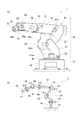
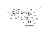
図1は、本実施例のロボット1の全体構造を示す説明図である。図1(a)には、本実施例のロボット1の大まかな外形形状が示されている。図示されるように、本実施例のロボット1は、地面に設置される基台10と、基台10に対して回転可能に取り付けられたアーム20と、基台10内に搭載されてロボット1の全体の動作を制御する制御部50とを備えている。
FIG. 1 is an explanatory diagram showing the overall structure of the
アーム20は、6つのアーム部材21〜26と、5つの関節42〜46とを備えている。この中のアーム部材21は、関節41によって回転可能に基台10に取り付けられている。また、アーム部材22は、関節42によって屈曲可能にアーム部材21に取り付けられており、アーム部材23は、関節43によって屈曲可能にアーム部材22に取り付けられている。更に、アーム部材24は、関節44によって回転可能にアーム部材23に取り付けられており、アーム部材25は、関節45によって屈曲可能にアーム部材24に取り付けられ、アーム部材26は、関節46によって回転可能にアーム部材25に取り付けられている。尚、アーム部材26の先端には、力センサー27を介して、ロボットハンド(いわゆるハンド部)や、溶接治具などの図示しない各種の治具(いわゆるエンドエフェクター)が装着される。力センサー27は、ロボットハンドやエンドエフェクターの重量や、把持したワークの重量などを検出することができる。尚、本実施例のロボット1は、ある関節を動かすことによって、それより先の関節の回転軸の向きが変化するロボット(いわゆる垂直多関節型ロボット)である。
The
また、関節41の部分には、関節41を駆動するための第1モーター41mが搭載されている。同様に、関節42の部分には関節42を駆動するための第2モーター42mが搭載され、関節43の部分には関節43を駆動するための第3モーター43mが、関節44の部分には第4モーター44mが、関節45の部分には第5モーター45mが、関節46の部分には第6モーター46mが搭載されている。
Further, a
これら6つのアーム部材21〜26のうちで最も基台10側のアーム部材21には、ジャイロセンサー30が取り付けられている。また、アーム部材23には、ジャイロセンサー31が取り付けられている。ここで、ジャイロセンサー30,31は、予め定められた直交する3軸(X軸、Y軸、Z軸)を回転軸とする角速度(あるいは慣性力)を出力可能なセンサーである。ジャイロセンサー30は、関節41の回転軸がジャイロセンサー30のZ軸と一致する向きに取り付けられている。また、ジャイロセンサー31は、関節43の回転軸がジャイロセンサー31の何れかの軸と一致する向きに取り付けられている。尚、本実施例では、慣性力として角速度を検出するものとして説明するが、ジャイロセンサー30,31の代わりに加速度センサーを用いても良い。尚、本実施例では、ジャイロセンサー30が本発明における「第1角速度センサー」に対応し、ジャイロセンサー31が本発明における「第2角速度センサー」に対応する。また、ジャイロセンサー30,31は、本発明おける「慣性センサー」にも対応する。更に、アーム部材21が本発明における「第1アーム部材」に対応する。
The
また、ジャイロセンサーとしては、光学式ジャイロセンサー、振動型ジャイロセンサーなどが知られているが、ジャイロセンサー30,31は、小型化が可能という理由から、圧電材料の薄膜を用いて形成した振動型ジャイロセンサーが採用されている。すなわち、光学式ジャイロセンサーは、サニャック効果を利用する原理上に理由から小型化が困難であるが、振動型ジャイロセンサーは、コリオリ力を利用して角速度を検出するので小型化が可能である。また、振動型ジャイロセンサーにも、圧電方式や静電方式などが知られているが、水晶、あるいは水晶以外の圧電材料の薄膜を用いて角速度を検出する圧電方式の振動型ジャイロセンサーは、小型で安価に作製することが可能である。尚、角速度を検出するジャイロセンサー30,31は、加速度を検出する加速度センサーに比べて以下の点で優れている。先ず、加速度センサーは、重力の影響を考慮する必要があるため、このことが誤差要因となる。これに対して、角速度を検出するジャイロセンサー30,31は、角速度を検出しているので重力の影響を考慮する必要がない。また、加速度センサーは、加速度の検出感度を高めようとするとサイズが大きくなる。これに対して、角速度を検出するジャイロセンサー30,31は角速度を検出するので、小型であっても検出感度を高めることが可能である。このため、ジャイロセンサー30,31の設置の自由度を高くすることができる。
As the gyro sensor, an optical gyro sensor, a vibration type gyro sensor, and the like are known. However, the
図1(b)には、本実施例のロボット1が備えるアーム部材21〜26や、関節41〜46、ジャイロセンサー30,31の位置関係が模式的に示されている。以下では、関節41の角度を角度θ1で表し、関節42の角度を角度θ2、関節43の角度を角度θ3、関節44の角度を角度θ4、関節45の角度を角度θ5、関節46の角度を角度θ6で表すものとする。
FIG. 1B schematically shows the positional relationship between the
図2は、制御部50の内部構成を示したブロック図である。図示されるように制御部50には、第1モーター41mを制御するための第1モーター制御部51や、第2モーター42mを制御するための第2モーター制御部52、第3モーター43mを制御するための第3モーター制御部53、第4モーター44mを制御するための第4モーター制御部54、第5モーター45mを制御するための第5モーター制御部55、第6モーター46mを制御するための第6モーター制御部56、ロボット1全体の動作を制御するための全体制御部50a、全体制御部50aが実行するプログラムなどを記憶したメモリー50mなどが搭載されている。
FIG. 2 is a block diagram showing an internal configuration of the
第1モーター41mには、第1モーター41mの回転角度θ1を検出する角度センサー41sが搭載されている。同様に、第2モーター42mには、第2モーター42mの回転角度θ2を検出する角度センサー42sが搭載されており、第3モーター43mには、第3モーター43mの回転角度θ3を検出する角度センサー43sが搭載され、第4モーター44mには、第4モーター44mの回転角度θ4を検出する角度センサー44sが、第5モーター45mには、第5モーター45mの回転角度θ5を検出する角度センサー45sが、第6モーター46mには、第6モーター46mの回転角度θ6を検出する角度センサー46sが搭載されている。そして、それぞれのモーター制御部は、制御対象とするモーターに搭載された角度センサーからの出力に基づいて、それぞれのモーターの動作を制御する。すなわち、例えば第6モーター制御部56は、角度センサー46sで検出した回転角度θ6に基づいて、第6モーター46mの動作を制御する。第3〜第5モーター制御部53〜55についても同様に、角度センサー43s〜45sで検出した回転角度θ3〜θ5に基づいて、第3〜第5モーター43m〜45mの動作を制御する。但し、第2モーター制御部52については、角度センサー42sで検出した回転角度θ2だけでなく、ジャイロセンサー31の出力や、第3モーター制御部53からの情報も用いて、第2モーター42mの動作を制御する。第2モーター制御部52が行う制御の詳細については後述する。
An
また、第1モーター制御部51については、角度センサー41sで検出した回転角度θ1だけでなく、ジャイロセンサー30の出力も用いて、第1モーター41mの動作を制御する。第1モーター制御部51が行う制御の詳細についても後述する。また、図2に示されるように、力センサー27の出力も制御部50に供給される。そして、制御部50は、角度センサー41s〜46sや、ジャイロセンサー30,31や、力センサー27の出力を、100Hz以上の周期でサンプリングする。
The first
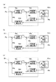
図3(a)は、第4モーター制御部54が第4モーター44mを制御する動作を示したブロック図である。また、図3(b)は、第5モーター制御部55が第5モーター45mを制御する動作を示したブロック図であり、図3(c)は、第6モーター制御部56が第6モーター46mを制御する動作を示したブロック図である。図示されるように、第4モーター制御部54、第5モーター制御部55、第6モーター制御部56は、制御対象が第4モーター44m、第5モーター45m、第6モーター46mと異なるだけで制御内容は全く同様である。そこで、図3(a)に示した第4モーター制御部54を例に用いて説明する。
FIG. 3A is a block diagram illustrating an operation in which the fourth
第4モーター制御部54は、図2に示した全体制御部50aから目標位置Pcを受け取って、角度センサー44sの回転角度θ4が目標位置Pcとなるような制御を行う。従って、基本的には角度センサー44sで検出した回転角度θ4をフィードバック制御する大きなループと、その内側で角速度をフィードバック制御する小さなループが回るような制御構造となっている。すなわち、図3(a)に示されるように、全体制御部50aからの目標位置Pcは位置制御部54aに入力される。この時、角度センサー44sで検出した回転角度θ4は、回転角度算出部54dで位置フィードバック値Pfbに変換された後、目標位置Pcから減算されて位置制御部54aに入力される。
The fourth
位置制御部54aでは、目標位置Pcと位置フィードバック値Pfbとの偏差に応じた目標角速度ωcを生成して、角速度制御部54bに入力する。また、この時、角度センサー44sで検出した回転角度θ4は、角速度算出部54cで角速度フィードバック値ωfbに変換された後、目標角速度ωcから減算されて角速度制御部54bに入力される。そして、角速度制御部54bでは、目標角速度ωcと角速度フィードバック値ωfbとの偏差に応じて、第4モーター44mを制御する。その結果が、角度センサー44sで検出する回転角度θ4に反映されて、回転角度算出部54dを介して位置フィードバック制御が行われ、角速度算出部54cを介して角速度フィードバック制御が行われる。
In the
図4は、第1モーター制御部51が第1モーター41mを制御する動作を示したブロック図である。第1モーター制御部51も、角度センサー41sで検出した回転角度θ1を用いて制御する。この点では、上述した第4モーター制御部54、第5モーター制御部55、第6モーター制御部56が行う制御と同様である。しかし、第1モーター制御部51は、ジャイロセンサー30の出力も用いて第1モーター41mの動作を制御する。このことと対応して、第1モーター制御部51が行う制御は、角度センサー41sで検出した回転角度θ1を用いて行う位置フィードバック制御および角速度フィードバック制御に、ジャイロセンサー30の出力を用いて行う角速度フィードバック制御を組み合わせたものとなっている。図4中では、回転角度θ1を用いて行う位置フィードバック制御および角速度フィードバック制御を実線の矢印で表し、ジャイロセンサー30の出力を用いて行う角速度フィードバック制御を破線の矢印で表している。以下、図4に従って説明する。
FIG. 4 is a block diagram illustrating an operation in which the first
第1モーター制御部51においても、全体制御部50aから目標位置Pcは位置制御部51aに入力される。この時、角度センサー41sで検出した回転角度θ1は、回転角度算出部51dで位置フィードバック値Pfbに変換された後、目標位置Pcから減算されて位置制御部51aに入力される。
Also in the first
位置制御部51aでは、目標位置Pcと位置フィードバック値Pfbとの偏差に応じた目標角速度ωcを生成して、角速度制御部51bに入力する。また、この時、角度センサー41sからの出力と、ジャイロセンサー30からの出力とに基づいて生成された角速度フィードバック値ωfbが目標角速度ωcから減算されて、角速度制御部51bに入力される。角度センサー41sからの出力と、ジャイロセンサー30からの出力とに基づいて角速度フィードバック値ωfbを生成する方法については後述する。
The
そして、角速度制御部51bでは、目標角速度ωcと角速度フィードバック値ωfbとの偏差に応じて、第1モーター41mを制御する。その結果、角度センサー41sで検出される回転角度θ1が変化する。また、第1モーター41mによってアーム部材21が回転する結果、ジャイロセンサー30からは角速度ωA1が出力される。このうち、角度センサー41sで検出した回転角度θ1は、回転角度算出部51dで位置フィードバック値Pfbに変換される。こうして得られた位置フィードバック値Pfbを目標位置Pcにフィードバックすることによって、位置フィードバック制御が行われる。
Then, the angular velocity control unit 51b controls the
一方、角速度フィードバック値ωfbは次のようにして生成される。先ず、角度センサー41sで検出された回転角度θ1は角速度算出部51cに供給される。そして、角速度算出部51cは回転角度θ1から、第1モーター41mの角速度ωm1と、アーム部材21の角速度ωA1m とを生成する。ここでアーム部材21の角速度ωA1m とは、第1モーター41mの角速度ωm1を、第1モーター41mとアーム部材21との間の関節41の減速比で除算した値である。このアーム部材21の角速度ωA1m は、本来は、ジャイロセンサー30から得られた角速度ωA1と一致する筈である。従って、これらの偏差は、関節41の回転軸を中心とするアーム部材21の振動成分を表している。
On the other hand, the angular velocity feedback value ωfb is generated as follows. First, the rotation angle θ1 detected by the
そこで、ジャイロセンサー30から得られた角速度ωA1から、アーム部材21の角速度ωA1m を減算することによって、振動成分に相当する振動加速度ωA1s を生成する。その後、このアーム部材21の振動加速度ωA1s を、変換部51eで関節41の減速比を乗算することによって第1モーター41mの振動加速度ωm1s に変換する。そして、この振動加速度ωm1s に、補正値算出部51fでゲイン係数Kaを乗算することによって、補正値Ka・ωm1s を算出する。こうして求めた補正値Ka・ωm1s と、角速度算出部51cで求めた角速度ωm1とを加算することによって、角速度フィードバック値ωfbを算出する。第1モーター制御部51では、このようにして角度センサー41sおよびジャイロセンサー30の出力から求めた角速度フィードバック値ωfbを用いて、角速度フィードバック制御を行う。尚、ロボット1の動作時にアーム20の振動を抑制するためには、ゲイン係数Kaを適切に設定しておくことが重要となる。本実施例のロボット1では、ゲイン係数Kaの設定にも特徴があるが、この点については後ほど詳しく説明する。
Therefore, the vibration acceleration ωA1s corresponding to the vibration component is generated by subtracting the angular velocity ωA1m of the
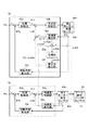
図5は、第2モーター制御部52が第2モーター42mを制御する動作と、第3モーター制御部53が第3モーター43mを制御する動作とを示したブロック図である。第2モーター制御部52の制御と第3モーター制御部53の制御とをまとめて表しているのは、図2に示したように、第2モーター制御部52が第2モーター42mを制御する際に、第3モーター制御部53からの情報を利用するためである。これと同時に、第2モーター制御部52が第2モーター42mを制御する際に出力を用いるジャイロセンサー31は、第3モーター43mによって駆動されるアーム部材23に搭載されているためである。
FIG. 5 is a block diagram illustrating an operation in which the second
もっとも、第3モーター制御部53だけに着目すれば、第3モーター制御部53が行う制御は、前述した第4モーター制御部54や、第5モーター制御部55、第6モーター制御部56が行う制御と同様である。そこで、先ず、第3モーター制御部53が行う制御について簡単に説明する。
However, if attention is paid only to the third
第3モーター制御部53では、図2に示した全体制御部50aから受け取った目標位置Pcが位置制御部53aに入力される。この時、角度センサー43sで検出した回転角度θ3は、回転角度算出部53dで位置フィードバック値Pfbに変換された後、目標位置Pcから減算されて位置制御部53aに入力される。位置制御部53aでは、目標位置Pcと位置フィードバック値Pfbとの偏差に応じた目標角速度ωcを生成して、角速度制御部53bに入力する。また、この時、角度センサー43sで検出した回転角度θ3は、角速度算出部53cで角速度フィードバック値ωfbに変換された後、目標角速度ωcから減算されて角速度制御部53bに入力される。そして、角速度制御部53bでは、目標角速度ωcと角速度フィードバック値ωfbとの偏差に応じて、第3モーター43mを制御する。その結果が、角度センサー43sで検出する回転角度θ3に反映されて、回転角度算出部53dを介して位置フィードバック制御が行われ、角速度算出部53cを介して角速度フィードバック制御が行われる。
In the third
また、第3モーター43mが駆動された結果、アーム部材23が回転するので、アーム部材23に搭載されたジャイロセンサー31からは角速度ωA3が出力される。第2モーター制御部52は、このジャイロセンサー31の出力を角速度フィードバック制御に利用する。ジャイロセンサー31の出力を角速度フィードバック制御に利用する基本的な方法は、第1モーター制御部51がジャイロセンサー30の出力を利用する方法と同様である。また、第2モーター制御部52は、第3モーター制御部53の角速度算出部53cで得られた角速度ωA3m も、角速度フィードバック制御に利用する。図5では、第2モーター制御部52が、ジャイロセンサー31の出力や、第3モーター制御部53の角速度算出部53cで得られた角速度ωA3m を用いて角速度フィードバック制御する部分を、破線の矢印で表している。
As a result of the
第2モーター制御部52においても、全体制御部50aから目標位置Pcは位置制御部52aに入力される。この時、角度センサー42sで検出した回転角度θ2は、回転角度算出部52dで位置フィードバック値Pfbに変換された後、目標位置Pcから減算されて位置制御部52aに入力される。位置制御部52aでは、目標位置Pcと位置フィードバック値Pfbとの偏差に応じた目標角速度ωcを生成して、角速度制御部52bに入力する。また、この時、角度センサー42sからの出力や、ジャイロセンサー31からの出力や、第3モーター制御部53の角速度算出部53cで得られた角速度ωA3m を用いて生成された角速度フィードバック値ωfbが目標角速度ωcから減算されて、角速度制御部52bに入力される。角度センサー42sからの出力と、ジャイロセンサー31からの出力や、第3モーター制御部53の角速度算出部53cで得られた角速度ωA3m に基づいて角速度フィードバック値ωfbを生成する方法については後述する。
Also in the second
そして、角速度制御部52bでは、目標角速度ωcと角速度フィードバック値ωfbとの偏差に応じて、第2モーター42mを制御する。その結果、角度センサー42sで検出される回転角度θ2が回転角度算出部52dで位置フィードバック値Pfbに変換される。こうして得られた位置フィードバック値Pfbを目標位置Pcにフィードバックすることによって、位置フィードバック制御が行われる。
Then, the angular
また、第2モーター42mが駆動されることによってアーム部材22が回転し、その結果、アーム部材23が回転してジャイロセンサー31からは角速度ωA3が出力される。この角速度ωA3は、第2モーター制御部52の角速度フィードバック値ωfbを介して、第2モーター42mの角速度フィードバック制御に用いられる。
Further, the
この第2モーター制御部52の角速度フィードバック値ωfbは、次のようにして生成される。先ず、角度センサー42sで検出された回転角度θ2は角速度算出部52cに供給される。そして、角速度算出部52cは回転角度θ2から、第2モーター42mの角速度ωm2と、アーム部材22の角速度ωA2m とを生成する。アーム部材22の角速度ωA2m は、第2モーター42mの角速度ωm2を、第2モーター42mとアーム部材22との間の関節42の減速比で除算することによって算出できる。
The angular velocity feedback value ωfb of the second
仮に、第3モーター43mが固定されているとしたら、アーム部材22とアーム部材23とは一体と考えて良いので、アーム部材22の角速度ωA2m は、本来は、ジャイロセンサー31から得られた角速度ωA3と一致する筈である。従って、これらの偏差は、第3モーター43mが固定されているとした場合のアーム部材22の振動成分を表している。しかし実際には、第3モーター43mは固定されていないので、関節43も回転する。従って、ジャイロセンサー31から得られた角速度ωA3から、アーム部材22の角速度ωA2m と、アーム部材23の角速度ωA3m とを減算することによって、関節42での振動成分に相当する振動加速度ωA2s を算出することができる。
If the
その後、こうして得られたアーム部材22の振動加速度ωA2s を、変換部52eで関節42の減速比を乗算することによって第2モーター42mの振動加速度ωm2s に変換する。そして、この振動加速度ωm2s に、補正値算出部52fでゲイン係数Kaを乗算することによって、補正値Ka・ωm2s を算出する。尚、このゲイン係数Kaは、第1モーター制御部51の補正値算出部51fで用いるゲイン係数Kaとは異なる値とすることもできる。こうして求めた補正値Ka・ωm2s と、角速度算出部52cで求めた角速度ωm2とを加算することによって、角速度フィードバック値ωfbを算出する。第2モーター制御部52では、このようにして角速度フィードバック制御を行う。尚、第2モーター制御部52においても、アーム20の振動を抑制するためにはゲイン係数Kaを適切に設定しておくことが重要となる。
Thereafter, the vibration acceleration ωA2s of the
第2モーター制御部52のゲイン係数Kaは、アーム部材22に対するアーム部材23の回転角度θ3に基づいて設定する。また、第1モーター制御部51のゲイン係数Kaは、アーム部材21に対するアーム部材22の回転角度θ2に基づいて設定する。尚、第1モーター制御部51のゲイン係数Kaについては、第2モーター制御部52のゲイン係数Kaとほぼ同様なので、先ず始めに、第2モーター制御部52のゲイン係数Kaについて説明する。
The gain coefficient Ka of the second
図6は、第2モーター制御部52のゲイン係数Kaを設定する際の回転角度θ3を示した説明図である。すなわち、アーム部材22の両側の関節42および関節43を結ぶ直線と、アーム部材23の両側の関節43および関節44を結ぶ直線とを考えて、これらの直線がなす角度を回転角度θ3として使用する。この回転角度θ3が180°に近付くほどアーム部材22とアーム部材23とが延びた状態となり、回転角度θ3が0°に近付くほどアーム部材22とアーム部材23とが折り畳まれた状態となる。本実施例では、回転角度θ3が180°に近付くほど、第2モーター制御部52のゲイン係数Kaを大きな値に設定し、回転角度θ3が0°に近付くほど、第2モーター制御部52のゲイン係数Kaを小さな値に設定する。これは次のような理由による。
FIG. 6 is an explanatory diagram showing the rotation angle θ3 when the gain coefficient Ka of the second
アーム部材22とアーム部材23とが延びた状態(回転角度θ3が180°に近い状態)では、関節42の回転軸まわりの慣性モーメントが大きくなるので、動作に伴い大きな振動が発生するようになる。その結果、振動抑制効果を高めるために、第2モーター42mが大きなトルクを発生させる必要があり、第2モーター制御部52のゲイン係数Kaは大きくすることが望ましい。また、アーム部材22とアーム部材23とが延びた状態では、アーム20の制御も不安定となりにくい。このため、第2モーター制御部52のゲイン係数Kaを大きな値に設定することで、アーム20の振動を速やかに抑制することができる。
In the state where the
また、アーム部材22とアーム部材23とが折り畳まれた状態(回転角度θ3が0°あるいは360°に近い状態)では、関節42の回転軸まわりの慣性モーメントが小さいので、それほど大きなトルクを発生させる必要はなく、従って、第2モーター制御部52のゲイン係数Kaを大きくしなくても振動を抑制することができる。また、アーム部材22とアーム部材23とが折り畳まれた状態では、アーム20の制御が不安定となりやすく、振動が発振し易いので、第2モーター制御部52のゲイン係数Kaを小さく設定しておいた方が、アーム20の制御が発振することを防止し、制御を安定させることができるので望ましい。
Further, when the
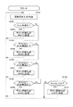
図7は、第2モーター制御部52のゲイン係数Kaを設定する処理のフローチャートである。第2モーター制御部52のゲイン係数Kaを設定するに際しては、先ず始めに、角度センサー43sの出力に基づいて回転角度θ3を検出する(ステップS101)。図6を用いて前述したように、回転角度θ3はアーム部材22とアーム部材23とがなす角度である。
FIG. 7 is a flowchart of processing for setting the gain coefficient Ka of the second
続いて、検出した回転角度θ3が第1閾値角度θth1 未満か否かを判断する(ステップS102)。ここで、第1閾値角度θth1 は、0°〜110°の範囲(より好ましくは45°〜90°の範囲)から選択された適切な角度(代表的には90°)に設定される。その結果、回転角度θ3が第1閾値角度θth1 未満であった場合は(ステップS102:yes)、第2モーター制御部52のゲイン係数KaをKa1に設定する(ステップS103)。ここでKa1は、0〜0.3の範囲(より好ましくは0〜0.2の範囲)から選択された適切な値に設定されている。
Subsequently, it is determined whether or not the detected rotation angle θ3 is less than the first threshold angle θth1 (step S102). Here, the first threshold angle θth1 is set to an appropriate angle (typically 90 °) selected from the range of 0 ° to 110 ° (more preferably, the range of 45 ° to 90 °). As a result, when the rotation angle θ3 is less than the first threshold angle θth1 (step S102: yes), the gain coefficient Ka of the second
これに対して、回転角度θ3が第1閾値角度θth1 未満ではなかった場合は(ステップS102:no)、回転角度θ3が第1閾値角度θth1 以上で、第2閾値角度θth2 未満であるか否かを判断する(ステップS104)。第2閾値角度θth2 は、60°〜150°の範囲(より好ましくは80°〜140°の範囲)から選択された適切な角度(代表的には135°)に設定される。その結果、回転角度θ3が第1閾値角度θth1 以上で第2閾値角度θth2 未満であった場合は(ステップS104:yes)、第2モーター制御部52のゲイン係数KaをKa2に設定する(ステップS105)。Ka2は、0〜0.5の範囲(より好ましくは0.1〜0.4の範囲)から選択された適切な値に設定されている。
On the other hand, if the rotation angle θ3 is not less than the first threshold angle θth1 (step S102: no), whether or not the rotation angle θ3 is equal to or greater than the first threshold angle θth1 and less than the second threshold angle θth2. Is determined (step S104). The second threshold angle θth2 is set to an appropriate angle (typically 135 °) selected from the range of 60 ° to 150 ° (more preferably, the range of 80 ° to 140 °). As a result, when the rotation angle θ3 is not less than the first threshold angle θth1 and less than the second threshold angle θth2 (step S104: yes), the gain coefficient Ka of the second
回転角度θ3が第1閾値角度θth1 以上で第2閾値角度θth2 未満ではなかった場合は(ステップS104:no)、回転角度θ3が第2閾値角度θth2 以上で、第3閾値角度θth3 未満であるか否かを判断する(ステップS106)。第3閾値角度θth3 は、210°〜300°の範囲(より好ましくは220°〜280°の範囲)から選択された適切な角度(代表的には225°)に設定される。その結果、回転角度θ3が第2閾値角度θth2 以上で第3閾値角度θth3 未満であった場合は(ステップS106:yes)、第2モーター制御部52のゲイン係数KaをKa3に設定する(ステップS107)。Ka3は、0.1〜0.8の範囲(より好ましくは0.2〜0.5の範囲)から選択された適切な値に設定されている。
If the rotation angle θ3 is not less than the first threshold angle θth1 and less than the second threshold angle θth2 (step S104: no), is the rotation angle θ3 greater than or equal to the second threshold angle θth2 and less than the third threshold angle θth3? It is determined whether or not (step S106). The third threshold angle θth3 is set to an appropriate angle (typically 225 °) selected from a range of 210 ° to 300 ° (more preferably a range of 220 ° to 280 °). As a result, when the rotation angle θ3 is equal to or larger than the second threshold angle θth2 and smaller than the third threshold angle θth3 (step S106: yes), the gain coefficient Ka of the second
回転角度θ3が第2閾値角度θth2 以上で第3閾値角度θth3 未満ではなかった場合は(ステップS106:no)、回転角度θ3が第3閾値角度θth3 以上で、第4閾値角度θth4 未満であるか否かを判断する(ステップS108)。第4閾値角度θth4 は、250°〜360°の範囲(より好ましくは270°〜315°の範囲)から選択された適切な角度(代表的には270°)に設定される。その結果、回転角度θ3が第3閾値角度θth3 以上で第4閾値角度θth4 未満であった場合は(ステップS108:yes)、第2モーター制御部52のゲイン係数KaをKa4に設定する(ステップS109)。Ka4は、0〜0.5の範囲(より好ましくは0.1〜0.4の範囲)から選択された適切な値に設定されている。
If the rotation angle θ3 is greater than or equal to the second threshold angle θth2 and not less than the third threshold angle θth3 (step S106: no), is the rotation angle θ3 greater than or equal to the third threshold angle θth3 and less than the fourth threshold angle θth4? It is determined whether or not (step S108). The fourth threshold angle θth4 is set to an appropriate angle (typically 270 °) selected from the range of 250 ° to 360 ° (more preferably, the range of 270 ° to 315 °). As a result, when the rotation angle θ3 is not less than the third threshold angle θth3 and less than the fourth threshold angle θth4 (step S108: yes), the gain coefficient Ka of the second
これに対して、回転角度θ3が第3閾値角度θth3 以上で第4閾値角度θth4 未満ではなかった場合は(ステップS108:no)、第2モーター制御部52のゲイン係数KaをKa5に設定する(ステップS110)。Ka5は、0〜0.3の範囲(より好ましくは0〜0.2の範囲)から選択された適切な値に設定されている。尚、第2モーター制御部52のゲイン係数Kaに設定されるKa1、Ka2、Ka3、Ka4、Ka5は、Ka1<Ka2<Ka3>Ka4>Ka5となるように設定されている。ここで、Ka1とKa5とは同じ値を用いることができるし、異なる値を用いることもできる。同様に、Ka2とKa4とは同じ値を用いることができるし、異なる値を用いることもできる。
On the other hand, when the rotation angle θ3 is not less than the third threshold angle θth3 and less than the fourth threshold angle θth4 (step S108: no), the gain coefficient Ka of the second
尚、上述した本実施例では、アーム部材22に対するアーム部材23の回転角度θ3を5つの範囲に分けて、それぞれの範囲について第2モーター制御部52のゲイン係数Kaを適切に設定するものとして説明した。しかし、必ずしも5つの範囲に分ける場合に限られるわけではなく、例えば、2つ、3つ、4つ、または、6つ以上の範囲に分けてもよい。また、第2モーター制御部52のゲイン係数Kaを段階状に変化させるのではなく、回転角度θ3に応じて連続してゲイン係数Kaを変化させても構わない。
In the above-described embodiment, the rotation angle θ3 of the
以上では、アーム部材22に対するアーム部材23の回転角度θ3に応じて、第2モーター制御部52のゲイン係数Kaを設定する処理について説明した。第1モーター制御部51のゲイン係数Kaについても、ほぼ同様にして行うことができる。すなわち、アーム部材21に対するアーム部材22の回転角度θ2を検出し(図7のステップS101に相当)、回転角度θ2を、予め設定しておいた閾値の角度と比較して(図7のステップS102、S104、S106、S108、S110に相当)、その大小関係に応じて第1モーター制御部51のゲイン係数Kaの値を設定すればよい(図7のステップS103、S105、S107、S109、S111に相当)。また、この時に比較する閾値の個数は、4つに限られるわけではなく、4つより少なくても良いし、4つより多くても良い。
The process for setting the gain coefficient Ka of the second
以上のようにすれば、回転角度θ3に応じて第2モーター制御部52のゲイン係数Kaを適切に設定し、回転角度θ2に応じて第1モーター制御部51のゲイン係数Kaを適切に設定することができるので、アーム20の振動を速やかに減衰させることが可能となる。尚、以下では、第2モーター制御部52のゲイン係数Ka、および第1モーター制御部51のゲイン係数Kaをまとめて、単にゲイン係数Kaと呼ぶことがある。
As described above, the gain coefficient Ka of the second
また、振動加速度ωA2s が逆位相になるときは、ゲイン係数Kaを負の値に設定することで、より速やかに振動を抑制して、制御を安定化させることができる。この場合、第2モーター制御部52のゲイン係数KaのKa1、Ka2、Ka3、Ka4、Ka5は、次のような値に設定される。
Further, when the vibration acceleration ωA2s is in the opposite phase, the vibration can be suppressed more quickly and the control can be stabilized by setting the gain coefficient Ka to a negative value. In this case, Ka1, Ka2, Ka3, Ka4, and Ka5 of the gain coefficient Ka of the second
先ず、Ka1は、−0.2〜0.3の範囲(より好ましくは−0.1〜0.1の範囲)から選択した適切な値とする。また、Ka2は、0.1〜0.4の範囲(より好ましくは0.1〜0.3の範囲)から選択した適切な値とする。Ka3は、0.3〜0.7の範囲(より好ましくは0.3〜0.6の範囲)から選択した適切な値とする。Ka4は、0.1〜0.4の範囲(より好ましくは0.1〜0.3の範囲)から選択した適切な値とする。更に、Ka5は、−0.2〜0.3の範囲(より好ましくは−0.1〜0.1の範囲)から選択した適切な値とすることができる。このような範囲からKa1、Ka2、Ka3、Ka4、Ka5を選択して設定することで、アーム20の振動を抑制して制御の安定化を実現することが可能となる。
First, Ka1 is set to an appropriate value selected from the range of -0.2 to 0.3 (more preferably, the range of -0.1 to 0.1). Ka2 is an appropriate value selected from the range of 0.1 to 0.4 (more preferably, the range of 0.1 to 0.3). Ka3 is an appropriate value selected from the range of 0.3 to 0.7 (more preferably, the range of 0.3 to 0.6). Ka4 is an appropriate value selected from the range of 0.1 to 0.4 (more preferably, the range of 0.1 to 0.3). Furthermore, Ka5 can be an appropriate value selected from the range of -0.2 to 0.3 (more preferably, the range of -0.1 to 0.1). By selecting and setting Ka1, Ka2, Ka3, Ka4, and Ka5 from such a range, it is possible to suppress the vibration of the
以上説明した本実施例のロボット1では、容易かつ確実に、アーム20の振動を抑制することができる。また、アーム20の先端側から逆ヤコビアンを解くなどの、膨大な演算が不要となる。このため、ロボット1の制御における応答速度を速くすることができ、また、制御部50の構成を簡素化することができる。また、逆ヤコビアンを解く場合のように特異点を含むような演算が存在しないので、演算が簡単になるだけでなく、制御が不能となる条件も存在しないので、ロボット1の制御を確実に実行することができる。
In the
加えて本実施例のロボット1は、アーム部材22を駆動する第2モーター42mの制御のために、アーム部材23に取り付けられたジャイロセンサー31の出力も使用している。このアーム部材23はアーム部材22よりも先端側に存在するので、ジャイロセンサー31の出力にはアーム部材23の振動に加えてアーム部材22の振動も含まれる。そのため、ジャイロセンサー31の出力を第2モーター42mの制御に利用すればアーム部材23およびアーム部材22の振動を併せて制御することが可能となり、振動抑制効果を高めることができる。また、より振動が大きい基台側の関節を制御することができるので、アーム部材22の振動をより一層有効に抑制することができる。更に、回転軸の方向が一致しているアーム部材23とアーム部材22とに対して1個のジャイロセンサー31で振動を抑制できるので、関節の数よりも少ない角速度センサーを用いてアームの振動を抑制することが可能となる。
In addition, the
また、ジャイロセンサー30はアーム部材21に取り付けられており、ジャイロセンサー31は、関節42、アーム部材22、および関節43を介してアーム部材21に接続されたアーム部材23に取り付けられている。そして、アーム部材21を回転させる関節41の回転軸と、関節42および関節43の回転軸とは直交している。このため、(ジャイロセンサー30が取り付けられた)アーム部材21の角速度と、(ジャイロセンサー31が取り付けられた)アーム部材23の角速度とを、互いに混在しない単純な回転成分として検出することができる。その結果、より簡単に、精度良く、且つ、確実に、アーム20の振動を抑制することが可能となる。更に、アーム部材21の角速度と、アーム部材23の角速度とが混在しない単純な回転成分として検出することができるので、それぞれの成分毎にフィードバック制御を行うことで、より確実にアーム20の振動を抑制することが可能となる。
The
加えて、アーム部材22に対するアーム部材23の回転角度θ3に応じてゲイン係数Kaを設定することで、制御を安定させつつ、アーム20の振動を確実に抑制することが可能となる。
In addition, by setting the gain coefficient Ka according to the rotation angle θ3 of the
更に加えて、本実施例のロボット1のように、アーム20の先端に取り付けられたエンドエフェクターやロボットハンドに掛かる荷重を、力センサー27を用いて検出する場合には、荷重の検出感度を高めるために力センサー27の部分の剛性が低くなり、アーム20全体の剛性が低下する。そして、アーム20全体の剛性が低下すると様々な次数の共振が発生し易くなるため、アーム20の振動を抑制することは困難となる。このため従来は、荷重の検出感度を低く抑える代わりに、アーム20全体の剛性を高く保つことによってアーム20の振動をできるだけ速やかに抑制するか、もしくは、アーム20の振動を速やかに抑制することは諦める代わりに、荷重を高い感度で検出することによって、例えば壊れ易いワークを把持可能とするかの、二者択一を迫られていた。しかし、本実施例のロボット1では、たとえアーム20全体の剛性が低くなっても、ジャイロセンサー30,31の出力をフィードバック制御することでアーム20の振動を速やかに抑制することができる。このため、アーム20の振動を速やかに抑制することと、例えば壊れ易いワークを把持するような微妙な制御を実現することとを、両立させることが可能となる。
In addition, when the load applied to the end effector or the robot hand attached to the tip of the
上述した本実施例のロボット1が、ジャイロセンサー30,31の出力をフィードバック制御することによる振動抑制可能なことを確認するために、以下のような確認試験を行った。先ず、図8(a)に示したように、アーム部材22〜26が水平に伸びた状態となるように関節42〜46を固定する。そして、関節41を回転させて、図8(b)に示すようにアーム20全体を90°回転させて停止させる。アーム20の先端が停止する位置にレーザー式変位計を設けておき、アーム20の先端の変位(振動)を実測した。また、アーム20を回転させる際には、関節41を最大角加速度2200°/s2、最大角速度275°/sで駆動した。アーム20の先端には、3kgの被計測部材を取り付けた。尚、レーザー式変位計のレーザーは被計測部材の表面に当てて、アーム20の先端の変位を測定している。
In order to confirm that the
図9は、実測結果を示す説明図である。図中の縦軸はレーザー式変位計で測定したアーム20先端の被計測部材の変位(単位はmm)であり、横軸は、アーム20を90°回転させた時点(アーム20の先端の被計測部材が目標位置を最初に通過した瞬間)からの経過時間(単位は秒)である。ちなみに、ロボット1の制御周期は8kHzであり、アーム20先端の変位は1msecのサンプリング間隔で計測した。
FIG. 9 is an explanatory diagram showing actual measurement results. The vertical axis in the figure is the displacement (unit: mm) of the member to be measured at the tip of the
図9中に示した破線は、ジャイロセンサー30,31の出力をフィードバック制御しなかった場合(ジャイロ制御なし)の実測結果を表している。これに対して、図9中に示した実線は、ジャイロセンサー30,31の出力をフィードバック制御した場合(ジャイロ制御あり)の実測結果を表している。図から明らかなように、ジャイロセンサー30,31の出力をフィードバック制御することで、アーム20の先端の振動を大幅に抑制可能であることが確認できる。尚、ジャイロ制御時のゲイン係数Kaは適切な値に設定されている。
A broken line shown in FIG. 9 represents an actual measurement result when the outputs of the
図10は、それぞれの場合について整定時間の計測結果を示した説明図である。ここで整定時間とは、アーム20の先端が停止位置(この場合は、関節41が90°回転した位置)を最初に通過してから、変位の振幅が±0.05mm以下になるまでに要する時間である。尚、図中には参考として、アーム20の先端に1kgの被計測部材を取り付けた場合も破線で示されている。
FIG. 10 is an explanatory diagram showing the measurement result of the settling time in each case. Here, the settling time is required until the displacement amplitude becomes ± 0.05 mm or less after the tip of the
図中に示されるように、アーム20の先端の被計測部材が3kgの条件では、ジャイロ制御なしの場合の整定時間が1.8秒であるのに対し、ジャイロ制御を行うと整定時間が0.6秒に短縮された。また、アーム20の先端の被計測部材が1kgの条件では、ジャイロ制御なしの場合の整定時間が1.3秒であるのに対し、ジャイロ制御を行うと整定時間が0.5秒に短縮された。もちろん、アーム20の先端に取り付けた被計測部材の重さが、1kgあるいは3kg以外の場合でも、ジャイロ制御を行うことで整定時間を大幅に短縮することができる。このように、アーム20の振動の抑制が困難な条件になるほど、ジャイロセンサー30,31の出力をフィードバック制御することで大きな振動抑制効果を得ることが可能となる。
As shown in the figure, when the member to be measured at the tip of the
また、上述した方向とは異なる方向にアーム20を回転させた場合についても、ジャイロ制御による振動抑制効果の確認試験を行った。すなわち、図11に示したようにアーム部材22〜26が水平に伸びた状態から、関節42を90°回転させて停止させる。この結果、関節42よりも先端側のアーム部材22〜26が振り上げられるような動作することになる。そして、アーム20の先端が停止する位置にレーザー式変位計を設けておき、アーム20の先端の変位(振動)を実測した。また、アーム20を回転させる際には、関節42を最大角加速度2200°/s2、最大角速度275°/sで駆動した。アーム20の先端には、3kgの被計測部材を取り付けた。尚、レーザー式変位計のレーザーは被計測部材の表面に当てて、アーム20の先端の変位を測定している。
Moreover, the confirmation test of the vibration suppression effect by gyro control was performed also when the
図12は、アーム20を振り上げた場合の確認試験によって求められた整定時間の計測結果を示した説明図である。ここで、アーム20を振り上げた場合(振り下げる場合も同様)の整定時間は、アーム20の先端が停止位置(この場合は、関節42が90°回転した位置)を最初に通過してから、変位の振幅が±0.1mm以下になるまでに要する時間として定義した。また、図中には参考として、アーム20の先端に5kgの被計測部材を取り付けた場合も破線で示されている。
FIG. 12 is an explanatory diagram showing the measurement result of the settling time obtained by the confirmation test when the
アーム20の先端の被計測部材が3kgの条件では、図中に実線で示されるように、ジャイロ制御なしの場合の整定時間が1.3秒であるのに対し、ジャイロ制御を行うと整定時間が0.4秒に短縮された。また、アーム20の先端の被計測部材が5kgの条件では、図中に破線で示されるように、ジャイロ制御なしの場合の整定時間が2.0秒であるのに対し、ジャイロ制御を行うと整定時間が0.6秒に短縮された。もちろん、アーム20の先端に取り付けた被計測部材の重さが、3kgあるいは5kg以外の場合でも、ジャイロ制御を行うことで整定時間を大幅に短縮することができる。このように、アーム20を振り上げる(あるいは振り下げる)場合にも、アーム20の振動の抑制が困難な条件になるほど、ジャイロセンサー30,31の出力をフィードバック制御することで、大きな振動抑制効果が得られることが確認できる。
Under the condition that the member to be measured at the tip of the
上述した本実施例のロボット1には、幾つかの変形例が存在する。以下、これらの変形例について、本実施例との相違点を中心として簡単に説明する。尚、変形例の説明に際しては、本実施例と同じ構成については同じ番号を符番することとして、改めての説明は省略する。
There are several variations of the
図13は、第1変形例のロボット2の構成を示した説明図である。上述した実施例および変形例では、アーム部材21のジャイロセンサー30と、アーム部材23のジャイロセンサー31とを搭載していた。しかし、アーム部材23に搭載するジャイロセンサー31の代わりに、アーム部材22にジャイロセンサー32を搭載しても良い。この場合、ジャイロセンサー32が搭載されたアーム部材22を駆動する第2モーター42mの制御は、ジャイロセンサー30が搭載されたアーム部材21を駆動する第1モーター41mの制御と同様となる。従って、第1変形例のロボット2における第2モーター制御部52の制御内容は、図4を用いて前述した第1モーター制御部51の制御内容と同様となる。
FIG. 13 is an explanatory diagram showing the configuration of the
また、第1変形例のロボット2のアーム部材23にはジャイロセンサー31は搭載されていないので、アーム部材23を駆動する第3モーター43mの制御は、アーム部材24を駆動する第4モーター44mや、アーム部材25を駆動する第5モーター45m、アーム部材26を駆動する第6モーター46mの制御と同様となる。従って、第1変形例のロボット2における第3モーター制御部53の制御内容は、図3を用いて前述した第4モーター制御部54や、第5モーター制御部55、第6モーター制御部56の制御内容と同様となる。
In addition, since the
図14は、第2変形例のロボット3の構成を示した説明図である。上述した実施例および第1変形例では、アーム部材21のジャイロセンサー30と、アーム部材23のジャイロセンサー31とを搭載していた。しかし、アーム部材22にもジャイロセンサー32を搭載しても良い。この場合、ジャイロセンサー32が搭載されたアーム部材22を駆動する第2モーター42mの制御、およびジャイロセンサー31が搭載されたアーム部材23を駆動する第3モーター43mの制御は、ジャイロセンサー30が搭載されたアーム部材21を駆動する第1モーター41mの制御と同様となる。従って、第2変形例のロボット3における第2モーター制御部52の制御内容、および第3モーター制御部53の制御内容は、図4を用いて前述した第1モーター制御部51の制御内容と同様とすればよい。
FIG. 14 is an explanatory diagram showing the configuration of the
特に、図14に示されるように第2変形例のロボット3では、ジャイロセンサー32が搭載されたアーム部材22を駆動する第2モーター42mの回転軸と、ジャイロセンサー31が搭載されたアーム部材23を駆動する第3モーター43mの回転軸とが平行となっている。このため、ジャイロセンサー32を用いた第2モーター42mの制御と、ジャイロセンサー31を用いた第3モーター43mの制御とを独立して行うのではなく、ジャイロセンサー32の出力を用いてジャイロセンサー31の出力を補正しても良い。
In particular, as shown in FIG. 14, in the
図15は、このような第2変形例のロボット3で、ジャイロセンサー32の出力を用いてジャイロセンサー31の出力を補正する場合に、第2モーター制御部52および第3モーター制御部53で行われる制御内容を例示した説明図である。上述したように、第2モーター制御部52および第3モーター制御部53で行われる制御内容は、図4を用いて前述した第1モーター制御部51の制御内容と同様である。但し、図15に示した第2変形例では、ジャイロセンサー31で検出したωA3は、そのまま第3モーター制御部53に入力されるのではなく、ジャイロセンサー32で検出した角速度ωA2を減算してから第3モーター制御部53に入力されている。
FIG. 15 shows the second
これは、次のような理由による。先ず、第2モーター42mの回転軸と第3モーター43mの回転軸とが平行なので、ジャイロセンサー31で検出される角速度ωA3は、第3モーター43mがアーム部材23を駆動したことによるものだけでなく、第2モーター42mがアーム部材22を駆動したことによるものが含まれている。従って、ジャイロセンサー31で検出した角速度ωA3から、ジャイロセンサー32で検出した角速度ωA2を減算してやることで、第3モーター43mがアーム部材23を駆動したことによる角速度を精度良く検出することが可能となるためである。その結果、アーム部材23の振動加速度ωA3s をより精度良く検出して、第3モーター43mの制御にフィードバックすることができるので、アーム20の振動を速やかに抑制することが可能となる。
This is due to the following reason. First, since the rotation axis of the
以上、本実施例および各種変形例について説明したが、本発明は上記の実施例および変形例に限られるものではなく、その要旨を逸脱しない範囲において種々の態様で実施することが可能である。 While the present embodiment and various modifications have been described above, the present invention is not limited to the above-described embodiment and modification, and can be implemented in various modes without departing from the spirit of the present invention.
1…ロボット、 2…ロボット、 3…ロボット、 10…基台、 20…アーム、 21〜26…アーム部材、 27…力センサー、 30〜32…ジャイロセンサー、 41〜46…関節、 41m…第1モーター、 41s…角度センサー、 42m…第2モーター、 42s…角度センサー、 43m…第3モーター、 43s…角度センサー、 44m…第4モーター、 44s…角度センサー、 45m…第5モーター、 45s…角度センサー、 46m…第6モーター、 46s…角度センサー、 50…制御部、 50a…全体制御部、 50m…メモリー、 51…第1モーター制御部、 51a…位置制御部、 51b…角速度制御部、 51c…角速度算出部、 51d…回転角度算出部、 51e…変換部、 51f…補正値算出部、 52…第2モーター制御部、 52a…位置制御部、 52b…角速度制御部、 52c…角速度算出部、 52d…回転角度算出部、 52e…変換部、 52f…補正値算出部、 53…第3モーター制御部、 53a…位置制御部、 53b…角速度制御部、 53c…角速度算出部、 53d…回転角度算出部、 54…第4モーター制御部、 54a…位置制御部、 54b…角速度制御部、 54c…角速度算出部、 54d…回転角度算出部、 55…第5モーター制御部、 56…第6モーター制御部。
DESCRIPTION OF
Claims (19)
前記第1アーム部材または前記第1関節に設けられた第1角速度センサーと、
を備えることを特徴とするロボット。 A plurality of joints including a second joint having a rotation direction different from that of the first joint and the first joint; and a first arm member provided rotatably with respect to a base via the first joint Including a plurality of arm members;
A first angular velocity sensor provided on the first arm member or the first joint;
A robot characterized by comprising:
前記複数のアーム部材の中で前記第1アーム部材とは異なる前記アーム部材に設けられた第2角速度センサーを備える
ことを特徴とするロボット。 The robot according to claim 1,
A robot comprising: a second angular velocity sensor provided on the arm member different from the first arm member among the plurality of arm members.
前記第2角速度センサーの出力に基づいて、前記第2角速度センサーが設けられた前記アーム部材よりも前記基台側の前記関節をフィードバック制御する制御部を備える
ことを特徴とするロボット。 The robot according to claim 2,
A robot comprising: a control unit that feedback-controls the joint on the base side relative to the arm member provided with the second angular velocity sensor based on an output of the second angular velocity sensor.
前記制御部は、前記第2角速度センサーが設けられた前記アーム部材の前記基台側の前記関節と回転軸が同じ方向の前記関節を、前記第2角速度センサーの出力に基づいてフィードバック制御する
ことを特徴とするロボット。 The robot according to claim 3,
The control unit feedback-controls the joint in the same direction as the joint on the base side of the arm member provided with the second angular velocity sensor based on the output of the second angular velocity sensor. Robot characterized by.
前記複数の関節によって連結された複数のアーム部材と、
前記複数のアーム部材の中の1の前記アーム部材に設けられた第1角速度センサーと、
前記第1角速度センサーが設けられた前記アーム部材とは異なる前記アーム部材に設けられた第2角速度センサーと、
を備えることを特徴とするロボット。 A plurality of joints including a first joint and a second joint having a rotation direction different from the first joint;
A plurality of arm members connected by the plurality of joints;
A first angular velocity sensor provided on one of the plurality of arm members;
A second angular velocity sensor provided on the arm member different from the arm member provided with the first angular velocity sensor;
A robot characterized by comprising:
前記第1角速度センサーの一軸の出力および前記第2角速度センサーの一軸の出力に基づいて、前記複数の関節を制御する制御部を備える
ことを特徴とするロボット。 The robot according to claim 5,
A robot comprising: a control unit that controls the plurality of joints based on a uniaxial output of the first angular velocity sensor and a uniaxial output of the second angular velocity sensor.
前記第1角速度センサーの一軸の出力および前記第2角速度センサーの三軸の出力に基づいて、前記複数の関節を制御する制御部を備える
ことを特徴とするロボット。 The robot according to claim 5,
A robot comprising: a control unit that controls the plurality of joints based on a uniaxial output of the first angular velocity sensor and a triaxial output of the second angular velocity sensor.
前記制御部は、前記第1角速度センサーの出力に基づいて、前記第1角速度センサーが設けられた前記アーム部材よりも前記基台側の前記関節をフィードバック制御し、且つ、前記第2角速度センサーの出力に基づいて、前記第2角速度センサーが設けられた前記アーム部材よりも前記基台側の前記関節をフィードバック制御する
ことを特徴とするロボット。 The robot according to claim 6 or 7, wherein
The control unit feedback-controls the joint on the base side of the arm member provided with the first angular velocity sensor based on the output of the first angular velocity sensor, and the second angular velocity sensor A robot that performs feedback control of the joint on the base side with respect to the arm member provided with the second angular velocity sensor based on an output.
前記第1角速度センサーの出力に基づいてフィードバック制御される前記関節の回転軸と、前記第2角速度センサーの出力に基づいてフィードバック制御される前記関節の回転軸とは直交している
ことを特徴とするロボット。 A robot according to any one of claims 6 to 8,
The rotation axis of the joint that is feedback-controlled based on the output of the first angular velocity sensor and the rotation axis of the joint that is feedback-controlled based on the output of the second angular velocity sensor are orthogonal to each other. Robot to do.
前記第1角速度センサーは、両側の前記関節の回転軸が互いに異なる前記アーム部材の中で前記基台に最も近い前記アーム部材に設けられている
ことを特徴とするロボット。 A robot according to any one of claims 6 to 9, wherein
The robot according to claim 1, wherein the first angular velocity sensor is provided on the arm member closest to the base among the arm members having different rotation axes of the joints on both sides.
前記第1角速度センサーは、振動型ジャイロセンサーである
ことを特徴とするロボット。 A robot according to any one of claims 1 to 10,
The robot according to claim 1, wherein the first angular velocity sensor is a vibration type gyro sensor.
前記第1角速度センサーは、圧電材料を含む
ことを特徴とするロボット。 The robot according to claim 11,
The robot according to claim 1, wherein the first angular velocity sensor includes a piezoelectric material.
前記複数の関節によって連結された複数のアーム部材と、
前記複数のアーム部材の中の1の前記アーム部材に設けられた角速度センサーと、
前記角速度センサーが設けられた前記アーム部材の前記基台側の前記関節と回転軸の方向が一致しており、且つ、前記基台側に設けられた前記関節を、前記角速度センサーの出力に基づいて制御する制御部と、
を備えることを特徴とするロボット。 A plurality of joints including a first joint and a second joint having a rotation direction different from the first joint;
A plurality of arm members connected by the plurality of joints;
An angular velocity sensor provided on one of the plurality of arm members;
The direction of the rotation axis coincides with the joint on the base side of the arm member provided with the angular velocity sensor, and the joint provided on the base side is based on the output of the angular velocity sensor. A control unit for controlling
A robot characterized by comprising:
前記アームに設けられた慣性センサーと、
前記慣性センサーの出力を100Hz以上の周期でサンプリングすることによって、前記第1関節を制御する制御部と、
を備えることを特徴とするロボット。 An arm including a first joint and a second joint having a rotation direction different from that of the first joint;
An inertial sensor provided on the arm;
A controller that controls the first joint by sampling the output of the inertial sensor at a cycle of 100 Hz or more;
A robot characterized by comprising:
前記アームに設けられた慣性センサーと、
前記慣性センサーよりも前記アームの先端側に設けられた力センサーと、
を備えることを特徴とするロボット。 An arm including a first joint and a second joint having a rotation direction different from that of the first joint;
An inertial sensor provided on the arm;
A force sensor provided closer to the tip of the arm than the inertial sensor;
A robot characterized by comprising:
前記アームに設けられた慣性センサーと、を備え、
前記第1関節の角加速度を2200°/s2で90°回動させた場合、前記アームの先端の振動が−0.05mmから+0.05mmになるまでの時間が1秒以下である
ことを特徴とするロボット。 An arm including a first joint provided on a base and a second joint having a rotation direction different from that of the first joint;
An inertial sensor provided on the arm,
When the angular acceleration of the first joint is rotated 90 ° at 2200 ° / s 2 , the time until the vibration at the tip of the arm changes from −0.05 mm to +0.05 mm is 1 second or less. Characteristic robot.
前記アームに設けられた慣性センサーと、を備え、
前記第1関節を最大角加速度で90°回動させた場合、前記アームの先端の振動が−0.05mmから+0.05mmになるまでの時間が1秒以下である
ことを特徴とするロボット。 An arm including a first joint provided on a base and a second joint having a rotation direction different from that of the first joint;
An inertial sensor provided on the arm,
When the first joint is rotated by 90 ° with a maximum angular acceleration, the time required for the vibration at the tip of the arm to change from −0.05 mm to +0.05 mm is 1 second or less.
前記アームに設けられた慣性センサーと、を備え、
前記第2関節の角加速度を2200°/s2で90°回動させた場合、前記アームの先端の振動が−0.1mmから+0.1mmになるまでの時間が0.5秒以下である
ことを特徴とするロボット。 An arm including a first joint provided on a base and a second joint having a rotation direction different from that of the first joint;
An inertial sensor provided on the arm,
When the angular acceleration of the second joint is rotated 90 ° at 2200 ° / s2, the time until the vibration at the tip of the arm changes from −0.1 mm to +0.1 mm is 0.5 seconds or less. Robot characterized by.
前記アームに設けられた慣性センサーと、を備え、
前記第1関節を最大角加速度で90°回動させた場合、前記アームの先端の振動が−0.05mmから+0.05mmになるまでの時間が1秒以下である
ことを特徴とするロボット。 An arm including a first joint provided on a base and a second joint having a rotation direction different from that of the first joint;
An inertial sensor provided on the arm,
When the first joint is rotated by 90 ° with a maximum angular acceleration, the time required for the vibration at the tip of the arm to change from −0.05 mm to +0.05 mm is 1 second or less.
Priority Applications (4)
| Application Number | Priority Date | Filing Date | Title |
|---|---|---|---|
| JP2013248935A JP2015104789A (en) | 2013-12-02 | 2013-12-02 | Robot |
| CN201410718044.8A CN104669244A (en) | 2013-12-02 | 2014-12-01 | Robot |
| US14/556,800 US9868209B2 (en) | 2013-12-02 | 2014-12-01 | Robot |
| US15/671,652 US9999974B2 (en) | 2013-12-02 | 2017-08-08 | Robot |
Applications Claiming Priority (1)
| Application Number | Priority Date | Filing Date | Title |
|---|---|---|---|
| JP2013248935A JP2015104789A (en) | 2013-12-02 | 2013-12-02 | Robot |
Publications (2)
| Publication Number | Publication Date |
|---|---|
| JP2015104789A true JP2015104789A (en) | 2015-06-08 |
| JP2015104789A5 JP2015104789A5 (en) | 2016-12-28 |
Family
ID=53435232
Family Applications (1)
| Application Number | Title | Priority Date | Filing Date |
|---|---|---|---|
| JP2013248935A Pending JP2015104789A (en) | 2013-12-02 | 2013-12-02 | Robot |
Country Status (1)
| Country | Link |
|---|---|
| JP (1) | JP2015104789A (en) |
Cited By (3)
| Publication number | Priority date | Publication date | Assignee | Title |
|---|---|---|---|---|
| JP2016175165A (en) * | 2015-03-20 | 2016-10-06 | トヨタ自動車株式会社 | Gyro sensor disposing method |
| US9950427B2 (en) | 2015-07-27 | 2018-04-24 | Seiko Epson Corporation | Robot, control apparatus, and robot system |
| JP2020011361A (en) * | 2018-07-20 | 2020-01-23 | セイコーエプソン株式会社 | Control device, horizontal multi-joint robot and robot system |
Citations (5)
| Publication number | Priority date | Publication date | Assignee | Title |
|---|---|---|---|---|
| JP2010274396A (en) * | 2009-06-01 | 2010-12-09 | Kawasaki Heavy Ind Ltd | Displacement correcting method and program in automatic operation system |
| JP2011011318A (en) * | 2009-07-06 | 2011-01-20 | Seiko Epson Corp | Position controlling method, robot |
| JP2012232370A (en) * | 2011-04-28 | 2012-11-29 | Seiko Epson Corp | Robot controller, simplified installation type robot, and method of controlling simplified installation type robot |
| JP2013099806A (en) * | 2011-11-08 | 2013-05-23 | Seiko Epson Corp | Robot and method for controlling the robot |
| JP2013146827A (en) * | 2012-01-20 | 2013-08-01 | Seiko Epson Corp | Method of controlling robot, and robot |
-
2013
- 2013-12-02 JP JP2013248935A patent/JP2015104789A/en active Pending
Patent Citations (5)
| Publication number | Priority date | Publication date | Assignee | Title |
|---|---|---|---|---|
| JP2010274396A (en) * | 2009-06-01 | 2010-12-09 | Kawasaki Heavy Ind Ltd | Displacement correcting method and program in automatic operation system |
| JP2011011318A (en) * | 2009-07-06 | 2011-01-20 | Seiko Epson Corp | Position controlling method, robot |
| JP2012232370A (en) * | 2011-04-28 | 2012-11-29 | Seiko Epson Corp | Robot controller, simplified installation type robot, and method of controlling simplified installation type robot |
| JP2013099806A (en) * | 2011-11-08 | 2013-05-23 | Seiko Epson Corp | Robot and method for controlling the robot |
| JP2013146827A (en) * | 2012-01-20 | 2013-08-01 | Seiko Epson Corp | Method of controlling robot, and robot |
Cited By (4)
| Publication number | Priority date | Publication date | Assignee | Title |
|---|---|---|---|---|
| JP2016175165A (en) * | 2015-03-20 | 2016-10-06 | トヨタ自動車株式会社 | Gyro sensor disposing method |
| US9950427B2 (en) | 2015-07-27 | 2018-04-24 | Seiko Epson Corporation | Robot, control apparatus, and robot system |
| JP2020011361A (en) * | 2018-07-20 | 2020-01-23 | セイコーエプソン株式会社 | Control device, horizontal multi-joint robot and robot system |
| JP7183601B2 (en) | 2018-07-20 | 2022-12-06 | セイコーエプソン株式会社 | ROBOT SYSTEM AND ROBOT SYSTEM CONTROL METHOD |
Similar Documents
| Publication | Publication Date | Title |
|---|---|---|
| US9868209B2 (en) | Robot | |
| JP6111563B2 (en) | robot | |
| JP6648913B2 (en) | Control method, robot apparatus, program, recording medium, article manufacturing method, and driving apparatus | |
| JP5962340B2 (en) | robot | |
| JP5652042B2 (en) | Robot apparatus, control method and program for robot apparatus | |
| US8972059B2 (en) | Displacement correcting method and displacement correcting program in automatic operation system | |
| JP7143633B2 (en) | ROBOT SYSTEM, CONTROL DEVICE AND CONTROL METHOD | |
| JP6575200B2 (en) | Robot, control device and robot system | |
| JP5417161B2 (en) | Robot vibration control method and robot control apparatus | |
| JP6248544B2 (en) | Robot, control device, robot system | |
| JP5891718B2 (en) | robot | |
| JP2008307634A (en) | Fitting device | |
| JP5916583B2 (en) | Weaving control device for articulated robot | |
| JP2017209762A (en) | Robot device, robot control method, program, recording medium and production method of article | |
| JP2015104789A (en) | Robot | |
| JP6581162B2 (en) | Processing system and processing machine control method | |
| JP5277946B2 (en) | Robot control device and robot system | |
| JP2020146794A (en) | Robot system, control device and control method | |
| JP6036476B2 (en) | robot | |
| JP2017056558A (en) | robot | |
| JP2020131388A (en) | Robot system, control device, and control method | |
| JP2017148913A (en) | Robot, control device, and control method for robot | |
| JP6252272B2 (en) | Position error suppression method for vertical articulated robot | |
| JP7121599B2 (en) | ROBOT SYSTEM AND ROBOT SYSTEM CONTROL METHOD | |
| JP2018202589A (en) | Control device, robot, and robot system |
Legal Events
| Date | Code | Title | Description |
|---|---|---|---|
| RD04 | Notification of resignation of power of attorney |
Free format text: JAPANESE INTERMEDIATE CODE: A7424 Effective date: 20160617 |
|
| RD03 | Notification of appointment of power of attorney |
Free format text: JAPANESE INTERMEDIATE CODE: A7423 Effective date: 20160627 |
|
| A521 | Request for written amendment filed |
Free format text: JAPANESE INTERMEDIATE CODE: A523 Effective date: 20161109 |
|
| A621 | Written request for application examination |
Free format text: JAPANESE INTERMEDIATE CODE: A621 Effective date: 20161109 |
|
| A131 | Notification of reasons for refusal |
Free format text: JAPANESE INTERMEDIATE CODE: A131 Effective date: 20170905 |
|
| A521 | Request for written amendment filed |
Free format text: JAPANESE INTERMEDIATE CODE: A523 Effective date: 20171018 |
|
| A02 | Decision of refusal |
Free format text: JAPANESE INTERMEDIATE CODE: A02 Effective date: 20171205 |