JP6135417B2 - Image forming control apparatus, image forming apparatus, and program - Google Patents
Image forming control apparatus, image forming apparatus, and program Download PDFInfo
- Publication number
- JP6135417B2 JP6135417B2 JP2013190805A JP2013190805A JP6135417B2 JP 6135417 B2 JP6135417 B2 JP 6135417B2 JP 2013190805 A JP2013190805 A JP 2013190805A JP 2013190805 A JP2013190805 A JP 2013190805A JP 6135417 B2 JP6135417 B2 JP 6135417B2
- Authority
- JP
- Japan
- Prior art keywords
- width
- image forming
- recording medium
- image
- continuous recording
- Prior art date
- Legal status (The legal status is an assumption and is not a legal conclusion. Google has not performed a legal analysis and makes no representation as to the accuracy of the status listed.)
- Expired - Fee Related
Links
Images


Description
本発明は、画像形成制御装置、画像形成装置、及びプログラムに関する。 The present invention relates to an image formation control device, an image formation device, and a program.
従来、トナー像を記録材上に形成する画像形成部及びトナー像を記録材に定着する定着装置を有する画像形成装置において、記録材の種別に対する、前記定着装置内での記録材の搬送速度の対応テーブルを複数有することを特徴とする画像形成装置が知られている(特許文献1)。 Conventionally, in an image forming apparatus having an image forming unit for forming a toner image on a recording material and a fixing device for fixing the toner image to the recording material, the conveyance speed of the recording material in the fixing device is determined with respect to the type of the recording material. An image forming apparatus having a plurality of correspondence tables is known (Patent Document 1).
本発明の目的は、記録媒体の幅が定着部材の加圧面の幅未満であることを警告する画像形成制御装置、画像形成装置、及びプログラムを提供することを目的とする。 An object of the present invention is to provide an image formation control device, an image formation device, and a program that warn that the width of the recording medium is less than the width of the pressing surface of the fixing member.
上記目的を達成するために、請求項1に記載の発明は、連続記録媒体の搬送方向と交差する方向の幅、及び着脱可能な定着部材における一対の加圧部材が形成する加圧面の、前記連続記録媒体の幅方向の幅とを取得する幅取得手段と、前記幅取得手段により取得された前記連続記録媒体の幅と前記加圧面の幅とを比較して、前記連続記録媒体の幅が前記加圧面の幅未満である場合に、前記加圧面の幅が、前記幅取得手段により取得された前記連続記録媒体の幅以下となる定着部材と交換することを案内する警告を出力するように出力手段を制御する制御手段とを含む、画像形成制御装置である。 In order to achieve the above object, the invention described in claim 1 is characterized in that the width in the direction intersecting the conveyance direction of the continuous recording medium and the pressure surface formed by the pair of pressure members in the detachable fixing member are a width obtaining means for obtaining a width direction of the width of the continuous recording medium is compared with the width of said pressing surface of the continuous recording medium obtained by the width obtaining means, the width of the continuous recording medium When the width of the pressure surface is less than the width of the pressure surface, a warning is output to guide the replacement of the pressure member with a fixing member whose width is equal to or less than the width of the continuous recording medium acquired by the width acquisition unit. And an image forming control apparatus including control means for controlling the output means.
請求項2に記載の発明は、前記制御手段は、前記幅取得手段により取得された前記連続記録媒体の幅が、前記加圧面の幅以上であり、かつ前記連続記録媒体に形成される画像の少なくとも一部分が、前記幅取得手段により取得された前記加圧面の、前記連続記録媒体の幅方向の範囲より外側に位置する場合、警告を出力するように前記出力手段を制御する請求項1記載の画像形成制御装置である。 According to a second aspect of the present invention, the control means is configured such that the width of the continuous recording medium acquired by the width acquisition means is equal to or larger than the width of the pressure surface and an image formed on the continuous recording medium. at least a portion of the width obtaining means and the pressure obtained by the pressure surface, when located outside the range of the width direction of the continuous recording medium, according to claim 1 Symbol placement for controlling the output means to output the warning The image forming control apparatus.
請求項3に記載の発明は、請求項1または請求項2記載の画像形成制御装置と、入力された画像情報に基づいて、前記連続記録媒体に画像を形成する画像形成手段と、を含む、画像形成装置である。 The invention according to claim 3 includes the image formation control device according to claim 1 or claim 2 , and image forming means for forming an image on the continuous recording medium based on the input image information. An image forming apparatus.
請求項4に記載の発明は、コンピュータを、連続記録媒体の搬送方向と交差する方向の幅、及び着脱可能な定着部材における一対の加圧部材が形成する加圧面の、前記連続記録媒体の幅方向の幅とを取得する幅取得手段、及び前記幅取得手段により取得された前記連続記録媒体の幅と前記加圧面の幅とを比較して、前記連続記録媒体の幅が前記加圧面の幅未満である場合に、前記加圧面の幅が、前記幅取得手段により取得された前記連続記録媒体の幅以下となる定着部材と交換することを案内する警告を出力するように出力手段を制御する制御手段、として機能させるためのプログラムである。 The invention according to claim 4, the computer, the direction of width intersecting the transport direction of the continuous recording medium, and a pair of detachable fixing member pressing surface of the pressure member is formed, the width of the continuous recording medium Width acquisition means for acquiring the width in the direction, and the width of the continuous recording medium acquired by the width acquisition means and the width of the pressure surface, and the width of the continuous recording medium is the width of the pressure surface The output means is controlled to output a warning for exchanging with a fixing member in which the width of the pressure surface is equal to or less than the width of the continuous recording medium acquired by the width acquisition means. It is a program for functioning as control means.
請求項1、請求項3、及び請求項4に記載の発明によれば、記録媒体の幅が定着部材における加圧面の幅未満であることを警告する。 According to the first, third , and fourth aspects of the invention, a warning is given that the width of the recording medium is less than the width of the pressing surface of the fixing member.
請求項2記載の発明によれば、記録媒体に形成される画像の幅が、定着部材における加圧面の幅よりも大きいことを警告する。 According to the second aspect of the invention, a warning is given that the width of the image formed on the recording medium is larger than the width of the pressing surface of the fixing member.
以下、本実施の形態について図面を参照しつつ説明する。図1は、本実施の形態に係る画像形成装置10の概略構成を示す図である。 Hereinafter, the present embodiment will be described with reference to the drawings. FIG. 1 is a diagram showing a schematic configuration of an image forming apparatus 10 according to the present embodiment.
<画像形成装置の全体構成>
本実施の形態に係る画像形成装置10は、図1に示すように、記録媒体を給紙する給紙装置12、給紙装置12から給紙された記録媒体Pに画像を形成する画像形成部14、及び画像形成部14によって画像が形成された記録媒体Pを収容する収容装置16と、給紙装置12、画像形成部14、及び収容装置16の各々を制御する制御装置18とを備えている。
<Overall configuration of image forming apparatus>
As shown in FIG. 1, an image forming apparatus 10 according to the present embodiment includes a
給紙装置12は、記録媒体として連続した長尺の連続紙Pを供給するものであり、収容装置16は画像形成部14によって画像形成された連続紙Pを収容する。
The
連続紙Pとしては、例えば、PP(ポリプロピレン)等の合成樹脂やグラシン紙や上質紙等の紙からなり、図2に示すように、一般的には台紙としての役割をもち使用時に廃棄される剥離紙51上に、中間層として糊等の粘着材料からなる粘着層52を介して最上層に設けられる表面基材53が粘着された所謂ラベル紙が用いられる。この表面基材53に図柄や文字が印刷されて使用される。このラベル紙5は、その用途にもよるが、例えば、表面基材53側が画像形成面である表面(外周面)に位置するようにロール状に巻かれたロール紙として配置されている。
The continuous paper P is made of, for example, a synthetic resin such as PP (polypropylene), paper such as glassine paper or high-quality paper, and generally has a role as a mount and is discarded when used as shown in FIG. A so-called label paper is used in which a
給紙装置12には、ロール状に巻き取られた連続紙Pからなる給紙ロール20が設けられており、図示しない駆動手段によって給紙ロール20が回転駆動されて、連続紙Pが画像形成部14へ供給される。
The
また、収容装置16には、画像形成された連続紙Pがロール状に巻き取られた収容ロール22が設けられている。
In addition, the
画像形成部14は、画像情報に基づいて、イエロー(Y)色、マゼンタ(M)色、シアン(C)色、及びブラック(K)色の4色のトナーを用いた画像を連続紙Pに形成する。この画像形成部14には、現像剤を構成するトナーで現像されたトナー像を形成する作像装置24と、作像装置24で形成されるトナー像をそれぞれ保持して最終的に連続紙Pに二次転写する二次転写位置まで搬送する中間転写装置26と、中間転写装置26で二次転写された連続紙P上のトナー像を定着させる定着装置28等を備えている。なお、連続紙Pにトナー像が形成される領域を被画像形成領域とする。
Based on the image information, the
作像装置24は、Y、M、C、Kの各色のトナー像をそれぞれ専用に形成する4つの作像装置24Y、24M、24C、24Kで構成されている。
The
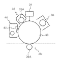
各作像装置24は、図3に示すように、回転する像保持体の一例としての感光体ドラム30を各々備えている。各感光体ドラム30の周囲には、後述する帯電装置32、露光装置34、現像装置36、一次転写装置38、及び清掃装置40等が設けられている。
As shown in FIG. 3, each
感光体ドラム30は、接地処理された円筒状または円柱状の基材の周面に感光材料からなる光導電性層(感光層)を有する像保持面が形成されている。また、感光体ドラム30は、図示しない駆動装置によって動力が伝達されて回転運動をするように支持されている。
The
帯電装置32は、感光体ドラム30に接触した状態で配置される接触型の帯電ロール32Aを含んで構成され、感光体ドラム30の像形成が可能な周面を帯電させる。帯電装置32には帯電用電圧が供給される。帯電用電圧としては、現像装置36が反転現像を行うものである場合、その現像装置36から供給されるトナーの帯電極性と同じ極性の電圧または電流が供給される。
The
露光装置34は、帯電された感光体ドラム30の周面に画像情報に基づく光を照射して感光体ドラム30の周面に静電潜像を形成する。
The
現像装置36は、露光装置34によって感光体ドラム30の周面に形成された静電潜像を各々対応する色の現像剤のトナーで現像してトナー像を生成する。現像装置36は、図示は省略するが、現像剤を感光体ドラム30と向き合う現像領域まで搬送する現像ロールと、現像剤を攪拌しながら現像ロールに供給するように搬送するスクリューオーガー等の攪拌搬送部材と、現像ロールに保持される現像剤の量を規制する層厚規制部材などを配置して構成されている。この現像装置36には、現像ロールと感光体ドラム30の間に現像用のバイアス電圧が印加されるようになっている。また、現像ロールや攪拌搬送部材は、図示しない回転駆動装置からの動力が伝達されて予め定めた方向に回転する。なお、現像剤としては、例えば、非磁性トナーと磁性キャリアとを含む二成分現像剤を使用することが可能である。また、現像装置36に供給されるトナーは、図1に示すように、各色のトナーを含む現像剤を収容したトナーカートリッジ42から供給される。
The developing
一次転写装置38は、感光体ドラム30の周面に接触して回転すると共に、一次転写用電圧が供給される一次転写ロール38Aを備えた接触型の転写装置とされている。一次転写ロール38Aに一次転写用電圧が供給されることにより、感光体ドラム30に形成された各色のトナー像が中間転写装置26に転写される。一次転写用電圧としては、トナーの帯電極性と逆の極性の直流電流が供給される。
The
また、清掃装置40は、一次転写後における感光体ドラム30の像保持面に残留して付着するトナー等の付着物を取り除いて清掃する。本実施の形態では、清掃装置40には、感光体ドラム30に接触するブレードが設けられており、このブレードによって感光体ドラム30の周面に付着した付着物が取り除かれるようになっている。
Further, the
中間転写装置26は、図1に示すように、各作像装置(24Y、24M、24C、24K)24の下方位置に配置されている。中間転写装置26は、本実施の形態では、感光体ドラム30と一次転写装置38の間となる一次転写位置を通過しながら図矢印A方向に回転する中間転写ベルト44と、中間転写ベルト44を回転自在に支持する複数の支持ローラ26A〜26Cと、中間転写ベルト44上のトナー像を連続紙Pに二次転写させる二次転写装置46と、を主に備えている。なお、中間転写装置26は、図示は省略するが、中間転写装置26を通過した後に中間転写ベルト44の外周面に残留して付着するトナーや、紙粉等の付着物を取り除いて清掃するベルト清掃装置を備えている。
As shown in FIG. 1, the
中間転写ベルト44としては、例えばポリイミド樹脂、ポリアミド樹脂等の合成樹脂にカーボンブラック等の抵抗調整剤などを分散させた材料で製作される無端状のベルトが使用される。 As the intermediate transfer belt 44, for example, an endless belt made of a material in which a resistance adjusting agent such as carbon black is dispersed in a synthetic resin such as polyimide resin or polyamide resin is used.
中間転写装置26は、図1に示すように、中間転写装置26におけるベルト支持ローラ26Cに支持されている中間転写ベルト44の外周面部分である二次転写位置において、中間転写ベルト44の周面に接触して回転すると共に二次転写用電圧が供給される二次転写ローラ46Aを備えた接触型の転写装置とされている。また、二次転写ローラ46A又は中間転写装置26の支持ローラ26Cには、トナーの帯電極性と逆極性又は同極性の直流電圧が二次転写用電圧として供給される。また、中間転写ベルト44上には、中間転写ベルト44に転写されたトナー像の濃度を検出するための濃度センサ48が設けられており、濃度センサ48の濃度検出結果に基づいて、トナーの供給量が制御されるようになっている。
As shown in FIG. 1, the
定着装置28は、図4に示すように表面温度が予め定められた温度に保持されるよう加熱手段によって加熱されるロール形態又はベルト形態の加熱用回転体28Aと、この加熱用回転体28Aに予め定めた圧力で接触して回転するロール形態又はベルト形態の加圧用回転体28Bなどを配置して構成されている。定着装置28では、加熱用回転体28A及び加圧用回転体28Bに連続紙Pが接触し、二次転写装置46によって連続紙Pに転写されたトナー像が加熱及び加圧されることにより、定着処理が行われる。また、定着装置28には、大きさが異なる複数の定着装置28があり、何れか一つの定着装置28が、画像形成部14に取り付けられる。大きさが異なる定着装置28を取り付ける場合には、画像形成部14から定着装置28が取り外されて交換される。
As shown in FIG. 4, the fixing
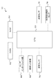
制御装置18は、画像形成装置10を制御する。制御装置18は、図5に示すようにCPU60と、ROM62と、RAM64と、ユーザインターフェイス部66と、画像入力装置68と、環境センサ70と、画像形成部14と、紙幅センサ76と、定着装置種別センサ78と、を主に備えている。なお、CPU60が、幅取得手段及び制御手段の一例である。
The
CPU60は、画像形成装置10の画像形成動作を統括して制御するCPUを示しており、CPU60は、ROM62に記憶されたプログラムやRAM64に記憶されたパラメータ等を参照して画像形成動作を制御する。
The
ユーザインターフェイス部66は、ユーザが画像を形成する記録媒体の種類やサイズ、あるいはプリント枚数等を入力する。また、ユーザインターフェイス部66は、CPU60から入力された警告メッセージを表示する。なお、定着装置28の加圧面に傷がつく旨の警告メッセージがユーザインターフェイス部66に表示されている場合、画像形成動作を実行するか否かの選択画面をユーザインターフェイス部66に表示させる。
The user interface unit 66 inputs the type and size of the recording medium on which the user forms an image, the number of prints, and the like. The user interface unit 66 displays a warning message input from the
画像入力装置68は、画像を入力する。 The image input device 68 inputs an image.
環境センサ70は、画像形成装置10の環境温度を検知する。 The environmental sensor 70 detects the environmental temperature of the image forming apparatus 10.
紙幅センサ76は、連続紙Pの搬送方向と直交する方向の連続紙Pの幅を検出する。なお、搬送方向と直交する方向の幅が、搬送方向と交差する方向の幅の一例である。 The paper width sensor 76 detects the width of the continuous paper P in the direction orthogonal to the conveyance direction of the continuous paper P. The width in the direction orthogonal to the transport direction is an example of the width in the direction intersecting the transport direction.
定着装置種別センサ78は、画像形成部14に取り付けられている定着装置28の種別を検出し、メモリ(図示省略)に記憶されている当該種別に対応した定着装置28の加熱用回転体28Aと加圧用回転体28Bとが形成する加圧面の、連続紙Pの幅方向の幅を取得する。具体的には、定着装置28に定着装置の種別を判別するためのチップを取り付けておき、定着装置種別センサ78が、当該チップを読み取ることにより当該定着装置28の種別を判断する。また、当該定着装置28の種別に対応して、当該定着装置28の加熱用回転体28Aと加圧用回転体28Bとが形成する加圧面の幅が、メモリに記憶されている。なお、定着装置28の加熱用回転体28A及び加圧用回転体28Bが定着部材の一例である。また、加熱用回転体28Aと加圧用回転体28Bとが形成する加圧面の幅が、定着部材における一対の加圧部材が形成する加圧面の記録媒体の幅方向の幅の一例である。
<画像形成装置の基本的な動作>
The fixing
<Basic operation of image forming apparatus>
続いて、画像形成装置10による基本的な画像形成動作について説明する。 Subsequently, a basic image forming operation by the image forming apparatus 10 will be described.
画像形成装置10は、画像形成動作(プリント)の要求を受け付けると、4つの作像装置(24Y、24M、24C、24K)24、中間転写装置26、二次転写装置46、及び定着装置28等が始動する。
Upon receiving a request for an image forming operation (printing), the image forming apparatus 10 includes four image forming devices (24Y, 24M, 24C, 24K) 24, an
そして、各作像装置24においては、まず各感光体ドラム30が回転されて、各帯電装置32によって各感光体ドラム30の表面が予め定めた極性及び電位にそれぞれ帯電される。続いて、露光装置34によって、帯電後の感光体ドラム30の表面に対し、画像情報に基づく光が照射されることにより、感光体ドラム30の表面に各色成分の静電潜像が形成される。
In each
続いて、各現像装置36によって、感光体ドラム30に形成された各色成分の静電潜像に、予め定めた極性に帯電された対応する色(Y、M、C、K)のトナーがそれぞれ供給されて静電的に付着され、静電潜像が現像される。これにより、感光体ドラム30に形成された各色成分の静電潜像が、その対応する色のトナーでそれぞれ現像された4色(Y、M、C、K)のトナー像として顕像化される。
Subsequently, toner of corresponding colors (Y, M, C, K) charged to a predetermined polarity is respectively applied to the electrostatic latent image of each color component formed on the
続いて、各作像装置24の感光体ドラム30上に形成された各色のトナー像が一次転写位置まで搬送されると、一次転写装置38によって、各色のトナー像が中間転写ベルト44に対して順番に重ね合わせるような状態で一次転写される。
Subsequently, when each color toner image formed on the
また、一次転写が終了した各作像装置24では、清掃装置40によって感光体ドラム30の表面に残留するトナー等の付着物が除去されて感光体ドラム30の表面が清掃される。これにより、各作像装置24は次の作像動作が可能な状態となる。
Further, in each
続いて、中間転写装置26では、中間転写ベルト44の回転により一次転写されたトナー像を保持して二次転写位置まで搬送される。一方、給紙装置12では、作像動作に先立って連続紙Pが給紙ロール20から予め定めた搬送経路に沿って二次転写位置まで供給される。
Subsequently, in the
二次転写位置においては、二次転写装置46によって、中間転写ベルト44上のトナー像が連続紙Pに一括して二次転写される。また、二次転写が終了した中間転写装置26では、図示しないベルト清掃装置によって、二次転写後の中間転写ベルト44の表面に残留したトナー等の付着物が除去される。
At the secondary transfer position, the toner image on the intermediate transfer belt 44 is secondarily transferred onto the continuous paper P all at once by the
続いて、トナー像が二次転写された連続紙Pは、定着装置28まで搬送されて、定着装置28によって定着処理が行われることにより連続紙Pにトナー像が定着される。そして、最後に、定着が終了した後の連続紙Pは、画像形成部14から排出されて、収容装置16の収容ロール22に巻き取られる。
Subsequently, the continuous paper P onto which the toner image has been secondarily transferred is conveyed to the fixing
以上の動作により、4色のトナー像を組み合わせからなるフルカラー画像が形成された連続紙Pが出力される。 With the above operation, the continuous paper P on which a full color image formed by combining four color toner images is formed is output.
<本実施の形態に係る警告処理>
次に、本発明の実施の形態に係る画像形成装置10で実行される「警告処理」について説明する。図6は「警告処理」の処理ルーチンの一例を示すフローチャートである。「警告処理」の制御プログラムは、記憶部(図示省略)から読み出され、画像形成動作(プリント)の要求を受け付けたときに、CPU60により実行される。
<Warning process according to this embodiment>
Next, the “warning process” executed by the image forming apparatus 10 according to the embodiment of the present invention will be described. FIG. 6 is a flowchart showing an example of the processing routine of “warning processing”. The “warning process” control program is read from the storage unit (not shown) and executed by the
まず、ステップS102では、紙幅センサ76によって検出された連続紙Pの幅を取得する。 First, in step S102, the width of the continuous paper P detected by the paper width sensor 76 is acquired.
次に、ステップS104では、定着装置種別センサ78によって検出された定着装置28の種別を取得し、メモリ(図示省略)に記憶されている当該種別に対応した定着装置28の加熱用回転体28Aと加圧用回転体28Bとが形成する加圧面の幅を取得する。
Next, in step S104, the type of the fixing
次に、ステップS105では、画像形成動作の要求に含まれる画像情報に基づいて、連続紙Pの被画像形成領域を求める。 Next, in step S105, the image forming area of the continuous paper P is obtained based on the image information included in the request for the image forming operation.
次に、ステップS106では、ステップS102において取得した連続紙Pの幅が、ステップS104において取得した定着装置28の加圧面の幅以上か否かの判定を行う。連続紙Pの幅が加圧面の幅以上である場合には、ステップS107へ移行し、連続紙Pの幅が加圧面の幅未満である場合には、ステップS110へ移行する。
Next, in step S106, it is determined whether or not the width of the continuous paper P acquired in step S102 is equal to or larger than the width of the pressure surface of the fixing
次に、ステップS107では、ステップS105において取得した被画像形成領域の少なくとも一部分が、ステップS104において取得した定着装置28の加圧面の幅方向の範囲よりも外側に位置するか否かの判定を行う。連続紙Pの被画像形成領域が、加圧面の幅方向の範囲よりも外側に位置しない場合には、ステップS108へ移行し、連続紙Pの被画像形成領域が、加圧面の幅方向の範囲よりも外側に位置する場合には、ステップS111へ移行する。
Next, in step S107, it is determined whether at least a part of the image forming area acquired in step S105 is located outside the range in the width direction of the pressure surface of the fixing
次に、ステップS108では、ステップS100において受け付けた画像形成動作要求に基づいて、画像形成動作の実行を行い、処理を終了する。 In step S108, the image forming operation is executed based on the image forming operation request received in step S100, and the process ends.
ステップS110では、定着装置28の加圧面に傷がつく旨の警告メッセージ、及び加圧面の幅が記録媒体の幅以下となる定着装置と交換することを案内するメッセージをユーザインターフェイス部66に表示させる。
In step S110, the user interface unit 66 displays a warning message that the pressure surface of the fixing
ステップS111では、画像形成動作が不可の旨の警告メッセージをユーザインターフェイス部66に表示させて、処理を終了する。 In step S111, a warning message indicating that the image forming operation cannot be performed is displayed on the user interface unit 66, and the process ends.
次に、ステップS112では、画像形成動作の指示の受け付けをしたか否かの判定を行う。画像形成動作指示の受け付けをした場合には、ステップS108へ移行し、画像形成動作指示の受け付けをしない場合には、処理を終了する。 In step S112, it is determined whether an instruction for an image forming operation has been accepted. If an image forming operation instruction has been accepted, the process proceeds to step S108. If an image forming operation instruction has not been accepted, the process ends.
以上説明したように、本実施の形態の画像形成装置によれば、記録媒体の幅が定着装置の加圧面の幅未満である場合に警告メッセージを表示して、定着装置の交換を促す。 As described above, according to the image forming apparatus of the present embodiment, when the width of the recording medium is less than the width of the pressure surface of the fixing device, a warning message is displayed to prompt replacement of the fixing device.
また、用紙エッジ傷及びラベル紙の粘着剤が定着装置の加圧面に付着することを防止することにより画質欠陥を防止することができる。 Further, it is possible to prevent image quality defects by preventing paper edge scratches and label paper adhesive from adhering to the pressure surface of the fixing device.
なお、本発明は、上述した実施形態に限定されるものではなく、この発明の要旨を逸脱しない範囲内で様々な変形や応用が可能である。 Note that the present invention is not limited to the above-described embodiment, and various modifications and applications are possible without departing from the gist of the present invention.
例えば、定着装置の種別を検知して、定着装置の加圧面の幅を取得する場合に限定されるものではなく、定着装置の加圧面の幅をセンサにより検知してもよい。 For example, the present invention is not limited to the case where the type of the fixing device is detected to acquire the width of the pressure surface of the fixing device, and the width of the pressure surface of the fixing device may be detected by a sensor.
また、本実施の形態においては、画像形成装置を構成する制御装置により、記録媒体の搬送方向と交差する方向の幅、及び定着装置の加圧面の幅を取得している場合について説明したが、これに限定されるものではない。例えば、外部端末(例えば、PC等)により、記録媒体の搬送方向と交差する方向の幅、及び定着装置の加圧面の幅を取得してもよい。 Further, in the present exemplary embodiment, a case has been described in which the control device configuring the image forming apparatus acquires the width in the direction intersecting the conveyance direction of the recording medium and the width of the pressure surface of the fixing device. It is not limited to this. For example, the width in the direction intersecting the conveyance direction of the recording medium and the width of the pressure surface of the fixing device may be acquired by an external terminal (for example, a PC).
また、本実施の形態においては、定着装置に、大きさが異なる複数の定着装置があり、何れか一つの定着装置が、画像形成部に取り付けられる画像形成装置の場合について説明したがこれに限定されるものではない。例えば、定着装置を交換できない画像形成装置に本発明を適用してもよい。 In this embodiment, the fixing device includes a plurality of fixing devices having different sizes, and one of the fixing devices is an image forming device attached to the image forming unit. However, the present invention is not limited to this. Is not to be done. For example, the present invention may be applied to an image forming apparatus in which the fixing device cannot be replaced.
また、本実施の形態においては、定着装置の加圧面の幅が、連続紙の幅以下であり、かつ、被画像形成領域の少なくとも一部分が、定着装置の加圧面の幅方向の範囲よりも外側に位置しない場合に画像を形成する場合について説明したがこれに限定されるものではない。例えば、定着装置の加圧面の幅が、連続紙の幅以上である場合に画像を形成してもよい。 In this embodiment, the width of the pressure surface of the fixing device is equal to or smaller than the width of the continuous paper, and at least a part of the image forming area is outside the range in the width direction of the pressure surface of the fixing device. However, the present invention is not limited to this. For example, the image may be formed when the width of the pressure surface of the fixing device is equal to or greater than the width of the continuous paper.
また、本願明細書中において、プログラムが予めインストールされている実施形態として説明したが、当該プログラムを、コンピュータ読み取り可能な記録媒体に格納して提供することも可能であるし、ネットワークを介して提供することも可能である。 Further, in the present specification, the embodiment has been described in which the program is installed in advance. However, the program can be provided by being stored in a computer-readable recording medium or provided via a network. It is also possible to do.
10 画像形成装置
14 画像形成部
18 制御装置
28B 加圧用回転体
28A 加熱用回転体
28 定着装置
66 ユーザインターフェイス部
76 紙幅センサ
78 定着装置種別センサ
DESCRIPTION OF SYMBOLS 10
Claims (4)
前記幅取得手段により取得された前記連続記録媒体の幅と前記加圧面の幅とを比較して、前記連続記録媒体の幅が前記加圧面の幅未満である場合に、前記加圧面の幅が、前記幅取得手段により取得された前記連続記録媒体の幅以下となる定着部材と交換することを案内する警告を出力するように出力手段を制御する制御手段と、
を含む画像形成制御装置。 A width acquisition means for acquiring a width in a direction intersecting a conveyance direction of the continuous recording medium, and a width in a width direction of the continuous recording medium of a pressure surface formed by a pair of pressure members in a detachable fixing member;
When the width of the continuous recording medium acquired by the width acquisition means is compared with the width of the pressure surface, and the width of the continuous recording medium is less than the width of the pressure surface, the width of the pressure surface is Control means for controlling the output means so as to output a warning for exchanging with a fixing member that is equal to or smaller than the width of the continuous recording medium acquired by the width acquisition means ;
An image forming control apparatus.
入力された画像情報に基づいて、前記連続記録媒体に画像を形成する画像形成手段と、
を含む、画像形成装置。 An image formation control device according to claim 1 or 2 ,
Image forming means for forming an image on the continuous recording medium based on the input image information;
An image forming apparatus.
連続記録媒体の搬送方向と交差する方向の幅、及び着脱可能な定着部材における一対の加圧部材が形成する加圧面の、前記連続記録媒体の幅方向の幅とを取得する幅取得手段、及び
前記幅取得手段により取得された前記連続記録媒体の幅と前記加圧面の幅とを比較して、前記連続記録媒体の幅が前記加圧面の幅未満である場合に、前記加圧面の幅が、前記幅取得手段により取得された前記連続記録媒体の幅以下となる定着部材と交換することを案内する警告を出力するように出力手段を制御する制御手段、
として機能させるためのプログラム。 Computer
A width acquisition means for acquiring a width in a direction intersecting a conveyance direction of the continuous recording medium, and a width in a width direction of the continuous recording medium of a pressure surface formed by a pair of pressure members in a detachable fixing member; and When the width of the continuous recording medium acquired by the width acquisition means is compared with the width of the pressure surface, and the width of the continuous recording medium is less than the width of the pressure surface, the width of the pressure surface is Control means for controlling the output means so as to output a warning for exchanging with a fixing member that is equal to or smaller than the width of the continuous recording medium acquired by the width acquisition means;
Program to function as.
Priority Applications (1)
| Application Number | Priority Date | Filing Date | Title |
|---|---|---|---|
| JP2013190805A JP6135417B2 (en) | 2013-09-13 | 2013-09-13 | Image forming control apparatus, image forming apparatus, and program |
Applications Claiming Priority (1)
| Application Number | Priority Date | Filing Date | Title |
|---|---|---|---|
| JP2013190805A JP6135417B2 (en) | 2013-09-13 | 2013-09-13 | Image forming control apparatus, image forming apparatus, and program |
Publications (3)
| Publication Number | Publication Date |
|---|---|
| JP2015055847A JP2015055847A (en) | 2015-03-23 |
| JP2015055847A5 JP2015055847A5 (en) | 2016-05-26 |
| JP6135417B2 true JP6135417B2 (en) | 2017-05-31 |
Family
ID=52820253
Family Applications (1)
| Application Number | Title | Priority Date | Filing Date |
|---|---|---|---|
| JP2013190805A Expired - Fee Related JP6135417B2 (en) | 2013-09-13 | 2013-09-13 | Image forming control apparatus, image forming apparatus, and program |
Country Status (1)
| Country | Link |
|---|---|
| JP (1) | JP6135417B2 (en) |
Families Citing this family (4)
| Publication number | Priority date | Publication date | Assignee | Title |
|---|---|---|---|---|
| JP6558070B2 (en) * | 2015-05-19 | 2019-08-14 | コニカミノルタ株式会社 | Image forming apparatus |
| JP6524792B2 (en) * | 2015-05-19 | 2019-06-05 | コニカミノルタ株式会社 | Image forming device |
| JP2017049452A (en) * | 2015-09-02 | 2017-03-09 | 富士ゼロックス株式会社 | Fixing device and image forming apparatus |
| JP6834615B2 (en) * | 2017-03-08 | 2021-02-24 | コニカミノルタ株式会社 | Fixing device and image forming device |
Family Cites Families (5)
| Publication number | Priority date | Publication date | Assignee | Title |
|---|---|---|---|---|
| JPS5647543U (en) * | 1979-09-17 | 1981-04-27 | ||
| JPS6198756U (en) * | 1984-12-04 | 1986-06-24 | ||
| JP2002229392A (en) * | 2001-01-29 | 2002-08-14 | Sharp Corp | Image forming device |
| JP2006119588A (en) * | 2004-09-22 | 2006-05-11 | Fuji Photo Film Co Ltd | Fixing device and image forming apparatus |
| JP2012234016A (en) * | 2011-04-28 | 2012-11-29 | Fuji Xerox Co Ltd | Image processing apparatus and image forming apparatus |
-
2013
- 2013-09-13 JP JP2013190805A patent/JP6135417B2/en not_active Expired - Fee Related
Also Published As
| Publication number | Publication date |
|---|---|
| JP2015055847A (en) | 2015-03-23 |
Similar Documents
| Publication | Publication Date | Title |
|---|---|---|
| JP5741656B2 (en) | Image forming apparatus and image forming program | |
| CN110058502B (en) | Image forming apparatus with a toner supply device | |
| US8971770B2 (en) | Developer-agitating transporter, developing device, and image forming apparatus | |
| CN105045068B (en) | Conveying device, developing apparatus and image forming apparatus | |
| JP6241154B2 (en) | Image forming apparatus and program | |
| JP6135417B2 (en) | Image forming control apparatus, image forming apparatus, and program | |
| JP2017138505A (en) | Developing device and image forming apparatus | |
| JP5682287B2 (en) | Image forming apparatus | |
| JP6098454B2 (en) | Image forming apparatus | |
| JP6171067B2 (en) | Image forming apparatus | |
| JP2007086377A (en) | Developing device and image forming apparatus | |
| US10248052B2 (en) | Resistance detection unit and image forming apparatus comprising the same | |
| JP6160380B2 (en) | Image forming apparatus and image forming program | |
| JP5890332B2 (en) | Image forming apparatus | |
| JP6903958B2 (en) | Image forming device | |
| US10289047B2 (en) | Image forming apparatus and non-transitory computer readable medium | |
| JP2017138349A (en) | Image formation apparatus | |
| JP2009294239A (en) | Image forming apparatus | |
| JP6014780B2 (en) | Image forming apparatus | |
| JP6490568B2 (en) | Image forming apparatus | |
| JP6111923B2 (en) | Image forming apparatus | |
| JP6407046B2 (en) | Image forming apparatus | |
| JP6187149B2 (en) | Image forming apparatus and program | |
| JP2009069368A (en) | Charging device, developing device, and image forming apparatus | |
| JP2016114814A (en) | Image formation device |
Legal Events
| Date | Code | Title | Description |
|---|---|---|---|
| A621 | Written request for application examination |
Free format text: JAPANESE INTERMEDIATE CODE: A621 Effective date: 20160309 |
|
| A521 | Written amendment |
Free format text: JAPANESE INTERMEDIATE CODE: A523 Effective date: 20160401 |
|
| A977 | Report on retrieval |
Free format text: JAPANESE INTERMEDIATE CODE: A971007 Effective date: 20161202 |
|
| A131 | Notification of reasons for refusal |
Free format text: JAPANESE INTERMEDIATE CODE: A131 Effective date: 20161206 |
|
| A521 | Written amendment |
Free format text: JAPANESE INTERMEDIATE CODE: A523 Effective date: 20170130 |
|
| TRDD | Decision of grant or rejection written | ||
| A01 | Written decision to grant a patent or to grant a registration (utility model) |
Free format text: JAPANESE INTERMEDIATE CODE: A01 Effective date: 20170328 |
|
| A61 | First payment of annual fees (during grant procedure) |
Free format text: JAPANESE INTERMEDIATE CODE: A61 Effective date: 20170410 |
|
| R150 | Certificate of patent or registration of utility model |
Ref document number: 6135417 Country of ref document: JP Free format text: JAPANESE INTERMEDIATE CODE: R150 |
|
| LAPS | Cancellation because of no payment of annual fees |