JP6130258B2 - Sheet cutting device - Google Patents
Sheet cutting device Download PDFInfo
- Publication number
- JP6130258B2 JP6130258B2 JP2013153746A JP2013153746A JP6130258B2 JP 6130258 B2 JP6130258 B2 JP 6130258B2 JP 2013153746 A JP2013153746 A JP 2013153746A JP 2013153746 A JP2013153746 A JP 2013153746A JP 6130258 B2 JP6130258 B2 JP 6130258B2
- Authority
- JP
- Japan
- Prior art keywords
- reel
- sheet
- stand
- release paper
- positioning
- Prior art date
- Legal status (The legal status is an assumption and is not a legal conclusion. Google has not performed a legal analysis and makes no representation as to the accuracy of the status listed.)
- Active
Links
- 230000007246 mechanism Effects 0.000 claims description 117
- 238000004804 winding Methods 0.000 claims description 17
- 230000008878 coupling Effects 0.000 claims description 15
- 238000010168 coupling process Methods 0.000 claims description 15
- 238000005859 coupling reaction Methods 0.000 claims description 15
- 238000001514 detection method Methods 0.000 claims description 8
- 238000012790 confirmation Methods 0.000 claims description 5
- 239000004820 Pressure-sensitive adhesive Substances 0.000 claims description 4
- 239000010410 layer Substances 0.000 claims description 4
- 239000012790 adhesive layer Substances 0.000 description 17
- 238000010586 diagram Methods 0.000 description 5
- 238000012840 feeding operation Methods 0.000 description 5
- 238000000034 method Methods 0.000 description 5
- 230000008569 process Effects 0.000 description 4
- 125000000391 vinyl group Chemical group [H]C([*])=C([H])[H] 0.000 description 3
- 229920002554 vinyl polymer Polymers 0.000 description 3
- 230000001105 regulatory effect Effects 0.000 description 2
- 230000006872 improvement Effects 0.000 description 1
- 230000001678 irradiating effect Effects 0.000 description 1
- 239000000463 material Substances 0.000 description 1
- 230000002035 prolonged effect Effects 0.000 description 1
- 230000009466 transformation Effects 0.000 description 1
Images


Landscapes
- Replacement Of Web Rolls (AREA)
- Control Of Cutting Processes (AREA)
- Nonmetal Cutting Devices (AREA)
- Adhesive Tape Dispensing Devices (AREA)
Description
本発明は、片面の一側縁に沿って粘着層が形成されると共に前記粘着層には離型紙が貼付された帯状のシートを所定の長さで切断するシート切断装置に関する。 The present invention relates to a sheet cutting apparatus for cutting a strip-like sheet having a predetermined length along an adhesive layer formed along one side edge of one side and having a release paper attached to the adhesive layer.
図17は、車両に搭載するワイヤハーネスの結束に使用されるシート110を示している。このシート110は、所定の幅Wの長尺に形成されたシート本体111と、該シート本体111の片面の一側縁に沿って所定の幅の帯状に形成される粘着層112と、粘着層112の上に貼付された離型紙113と、を備えている。シート本体111には、例えば、ビニール製のシートが使用される。
FIG. 17 shows a
図18は、図17に示したシート110によって、ワイヤハーネス120を結束した状態を示している。シート110は、離型紙113を剥離させて露出した粘着層112によってシート110の両側縁を貼り合わせることで、ワイヤハーネス120を収容して保持する筒状構造に形成される。
FIG. 18 shows a state in which the
図19は、図17に示したシート110を所定の長さで切断するような用途で使用されるシート切断装置200を示している。
このシート切断装置200は、下記特許文献1に開示された装置で、シート用リール210と、離型紙用リール220と、リールスタンド230と、シート送り機構240と、シート切断機構250と、を備える。
FIG. 19 shows a
The
シート用リール210は、片面に離型紙が貼付されている帯状のシート260を巻回したリールである。シート260は、図17に示したシート110と同様の構造でよい。
The
離型紙用リール220は、シート260から剥離された離型紙を巻き取るリールである。
The
リールスタンド230は、シート用リール210を回転可能に支持する第1リール支持部231と、離型紙用リール220を回転可能に支持する第2リール支持部232と、を有している。
The
シート送り機構240は、シート用リール210からシート繰り出し口270に至るシート走行経路に臨んで配置されたローラ241,242によって、シート260を一定速度で送り出す。
The
シート切断機構250は、シート送り機構240により繰り出されるシート260を所定の長さで切断する。
The
ところで、特許文献1のシート切断装置200の場合、リールスタンド230上のシート260を使い切った場合には、シート切断装置200の運転を停止させて、空になったシート用リール210をリールスタンド230の第1リール支持部231から取り外して、シート260が装填済のシート用リール210をシート用リール210に再装着する。
By the way, in the case of the
また、シート用リール210を交換したときには、新たに第1リール支持部231に装着したシート用リール210から引き出したシート260の先端部から離型紙を剥がし、剥がした剥離紙を離型紙用リール220まで導いて離型紙用リール220固定する剥離紙誘導作業も必要になる。
Further, when the
ところが、剥離紙誘導作業は手間のかかる作業で、シート用リール210の交換に引き続いて、剥離紙誘導作業を実施すると、作業時間が長引いて、その間、シート切断装置200の運転が停止されたままになるため、装置の稼働率が低下するという問題が生じた。
However, the release paper guiding operation is a time-consuming operation. If the release paper guiding operation is performed following the replacement of the
そこで、本発明の目的は、上記課題を解消することに係り、装置本体に組み付けられているリールスタンド上のシートを使い切って、シートを補充する際の作業時間を短縮して、装置の稼働率を高めることのできるシート切断装置を提供することにある。 Accordingly, an object of the present invention is to solve the above-mentioned problems, use up the sheet on the reel stand assembled to the apparatus main body, shorten the work time when replenishing the sheet, and improve the operation rate of the apparatus. An object of the present invention is to provide a sheet cutting apparatus capable of increasing the height.
本発明の前述した目的は、下記の構成により達成される。
(1) 片面の一側縁に沿って粘着層が形成されると共に前記粘着層には離型紙が貼付された帯状のシートを巻回したシート用リールと、
前記シートから剥離した前記離型紙を巻き取るための離型紙用リールと、
前記シート用リールを回転可能に支持する第1リール支持部と、前記離型紙用リールを回転可能に支持する第2リール支持部と、を有するリールスタンドと、
前記リールスタンドを着脱可能なスタンド取付部と、該スタンド取付部に取り付けられた前記リールスタンド上の前記シート用リールから前記シートを繰り出すシート送り機構と、前記シート送り機構により繰り出される前記シートを所定の長さに切断するシート切断機構と、前記シート送り機構によって送り出された前記シート上の前記離型紙が前記離型紙用リールに逐次巻き取られるように前記シート送り機構に連動して前記リールスタンド上の前記離型紙用リールを回転駆動する離型紙リール駆動軸と、を具備した装置本体と、
を備えるシート切断装置であって、
前記リールスタンドは、前記第1リール支持部に取り付けられた前記シート用リールに巻回されている前記シートの先端を支持すると共に前記リールスタンドを前記スタンド取付部に取り付けた際に支持している前記シートの先端を前記シート送り機構に渡すシート先端支持部材を備え、
前記スタンド取付部と前記リールスタンドとの間には、前記リールスタンドを前記スタンド取付部に取り付ける際に、簡単に且つ正確に前記リールスタンドを位置決めすることができて前記リールスタンドの交換を容易にするスタンド位置決め機構を備えたことを特徴とするシート切断装置。
The above-described object of the present invention is achieved by the following configuration.
(1) A sheet reel in which a pressure-sensitive adhesive layer is formed along one side edge of one surface and a belt-like sheet having a release paper attached to the pressure-sensitive adhesive layer is wound thereon,
A release paper reel for winding up the release paper released from the sheet;
A reel stand comprising: a first reel support portion that rotatably supports the sheet reel; and a second reel support portion that rotatably supports the release paper reel;
A stand mounting portion to which the reel stand can be attached and detached, a sheet feeding mechanism for feeding the sheet from the reel for sheet on the reel stand attached to the stand mounting portion, and the sheet fed by the sheet feeding mechanism A sheet cutting mechanism that cuts the length of the sheet, and the reel stand in conjunction with the sheet feeding mechanism so that the release paper on the sheet fed by the sheet feeding mechanism is sequentially wound on the release paper reel. A release paper reel drive shaft that rotationally drives the release paper reel above, an apparatus main body,
A sheet cutting device comprising:
The reel stand supports a front end of the sheet wound around the reel for the sheet attached to the first reel support portion and supports the reel stand when the reel stand is attached to the stand attachment portion. A sheet leading end support member for passing the leading end of the sheet to the sheet feeding mechanism;
When the reel stand is attached to the stand attachment portion, the reel stand can be easily and accurately positioned between the stand attachment portion and the reel stand, and the reel stand can be easily replaced. A sheet cutting device comprising a stand positioning mechanism.
(2) 前記スタンド位置決め機構は、前記リールスタンドの底部に架設された2本の位置決め用ロッドと、前記スタンド取付部に突設されて前記リールスタンドを前記スタンド取付部に載せたときに前記2本の位置決め用ロッドが形成する隙間の片側に嵌合する略直方体状の位置決め用ブロックと、
前記シート送り機構に設けられた位置決めピンと、前記シート先端支持部材に設けられた位置決め穴と、
を備え
2本の前記位置決め用ロッド間への前記位置決め用ブロックの嵌合、及び前記位置決めピンと前記位置決め穴との嵌合によって、前記リールスタンドを位置決めすることを特徴とする上記(1)に記載のシート切断装置。
(2) The stand positioning mechanism includes two positioning rods erected on the bottom of the reel stand, and the 2 when the reel stand is placed on the stand attaching portion so as to protrude from the stand attaching portion. A substantially rectangular parallelepiped positioning block that fits on one side of the gap formed by the positioning rods;
A positioning pin provided in the sheet feeding mechanism, a positioning hole provided in the sheet leading end support member,
The reel stand is positioned by fitting the positioning block between the two positioning rods and fitting the positioning pin and the positioning hole. Sheet cutting device.
(3) 前記シート送り機構は、前記シートの片面に当接した状態で回転駆動されることで前記シートを送り出す送りローラと、前記シートの片面に当接して前記シートの走行に追従して回転する測長用ローラと、を備え、
前記測長用ローラの回転量から前記シートの繰り出し長が検知されることを特徴とする上記(1)又は(2)に記載のシート切断装置。
(3) The sheet feeding mechanism is rotated while being in contact with one side of the sheet, and is rotated to follow the running of the sheet by contacting the one side of the sheet with a feeding roller that feeds the sheet. A measuring roller for measuring,
The sheet cutting device according to (1) or (2), wherein a feeding length of the sheet is detected from a rotation amount of the length measuring roller.
(4) 前記第2リール支持部は、前記離型紙用リールの中心を挿通して前記離型紙用リールと一体に回転する第2リール支持軸と、該第2リール支持軸の一端を回転自在に支持する軸受け部と、前記軸受け部に支持された前記第2リール支持軸の自由端を待機位置と該待機位置から軸方向に規定長だけ離間した結合位置とに位置切り替え可能にする軸移動機構と、を備え、
前記装置本体の前記スタンド取付部には、前記スタンド取付部に取り付けられた前記リールスタンド上の前記第2リール支持軸が前記結合位置に移動したときに前記第2リール支持軸の自由端と結合状態となって、前記第2リール支持軸を回転駆動可能な離型紙リール駆動軸を備え、
前記離型紙リール駆動軸は、前記送りローラと連動して駆動される、
ことを特徴とする上記(3)に記載のシート切断装置。
(4) The second reel support portion includes a second reel support shaft that is inserted through the center of the release paper reel and rotates integrally with the release paper reel, and one end of the second reel support shaft is rotatable. And a shaft movement enabling the position of the free end of the second reel support shaft supported by the bearing portion to be switched between a standby position and a coupling position spaced apart from the standby position by a specified length in the axial direction. A mechanism,
The stand attachment portion of the apparatus main body is coupled to the free end of the second reel support shaft when the second reel support shaft on the reel stand attached to the stand attachment portion moves to the coupling position. A release paper reel drive shaft capable of rotating and driving the second reel support shaft,
The release paper reel drive shaft is driven in conjunction with the feed roller;
The sheet cutting device according to (3) above, wherein
(5) 前記離型紙リール駆動軸を駆動する機構には、前記離型紙リール駆動軸の駆動トルクを規定値以内に制限するトルクリミッターが備えられていて、駆動トルクが既定値を超えないように前記離型紙リール駆動軸の回転速度が制御されることを特徴とする上記(4)に記載のシート切断装置。 (5) The mechanism for driving the release paper reel drive shaft is provided with a torque limiter for limiting the drive torque of the release paper reel drive shaft to within a specified value so that the drive torque does not exceed a predetermined value. The sheet cutting device according to (4), wherein the rotational speed of the release paper reel drive shaft is controlled.
(6) 前記シート切断機構は、前記シート送り機構から送り出される前記シートの表面と直交する方向に進退可能に前記シート送り機構の下流側に配置されたカッター刃と、前記測長用ローラの回転量に基づいて前記カッター刃を前記シートの走行位置に進退させるクランク機構と、を備えることを特徴とする上記(3)〜(5)の何れかに記載のシート切断装置。 (6) The sheet cutting mechanism includes a cutter blade disposed on the downstream side of the sheet feeding mechanism so as to advance and retreat in a direction perpendicular to the surface of the sheet fed from the sheet feeding mechanism, and rotation of the length measuring roller. The sheet cutting apparatus according to any one of (3) to (5), further comprising: a crank mechanism that moves the cutter blade back and forth to a traveling position of the sheet based on a quantity.
(7) 前記リールスタンドは、前記シート先端支持部材に支持されている前記シートの先端から剥がして前記離型紙用リールに固定された前記離型紙の前記離型紙用リールに至る経路を規制する離型紙経路設定部材、を備え、
前記装置本体の前記スタンド取付部には、前記スタンド取付部に取り付けられた前記リールスタンド上で前記離型紙用リールに巻き取られる前記離型紙の経路に光を照射して、照射した光の反射の有無により離型紙切れを検知する離型紙切れ検知確認センサを備えたことを特徴とする上記(1)〜(6)の何れかに記載のシート切断装置。
(7) The reel stand regulates a path of the release paper that is peeled off from the front end of the sheet supported by the sheet front end support member and fixed to the release paper reel to the release paper reel. A pattern routing member,
The stand mounting portion of the apparatus main body irradiates light onto the path of the release paper wound around the release paper reel on the reel stand attached to the stand mounting portion, and reflects the irradiated light The sheet cutting device according to any one of (1) to (6) above, further comprising a release paper piece detection confirmation sensor that detects the release paper piece depending on the presence or absence of the release paper.
上記(1)の構成によれば、リールスタンドは、装置本体のスタンド取付部に取り付けた際には、当該リールスタンドにセットされているシート用リールから引き出されたシートの先端が、シート先端支持部材によって、装置本体側のシート送り機構に渡される。そのため、リールスタンドを装置本体のスタンド取付部に取り付けると、直ぐに、シートを所定の長さずつ繰り出して切断する作業が可能になる。また、リールスタンドは、シート送り機構が繰り出すシートの先端から剥がした離型紙を巻き取る離型紙用リールを備えている。そしてリールスタンドに装備されている離型紙用リールは、リールスタンドを装置本体のスタンド取付部に取り付けると、装置本体の離型紙リール駆動軸により駆動可能になり、シート送り機構によるシートの繰り出し処理に連動して離型紙の巻き取りが可能になる。 According to the configuration of (1) above, when the reel stand is attached to the stand mounting portion of the apparatus main body, the leading end of the sheet pulled out from the sheet reel set on the reel stand is supported by the leading end of the sheet. The member passes the sheet feeding mechanism on the apparatus main body side. For this reason, when the reel stand is attached to the stand attachment portion of the apparatus main body, it becomes possible to immediately feed out and cut the sheet by a predetermined length. The reel stand includes a release paper reel that winds up the release paper peeled off from the leading edge of the sheet fed by the sheet feeding mechanism. When the reel stand is attached to the stand mounting portion of the apparatus main body, the release paper reel mounted on the reel stand can be driven by the release paper reel drive shaft of the apparatus main body, and the sheet feeding mechanism performs sheet feeding processing. In conjunction with this, release paper can be taken up.
即ち、上記(1)の構成によれば、リールスタンドを装置本体のスタンド取付部に取り付けると、直ちに、リールスタンド上のシート用リールからシートを繰り出して所定長に切断する作業や、シートから剥がした離型紙を離型紙用リールに巻き取る作業が可能になる。 That is, according to the configuration of (1) above, when the reel stand is attached to the stand mounting portion of the apparatus main body, the sheet is immediately fed out from the sheet reel on the reel stand and cut to a predetermined length, or peeled off from the sheet. It is possible to take up the release paper on the release paper reel.
また、スタンド取付部とリールスタンドとの間には、リールスタンドをスタンド取付部に取り付ける際に、簡単に且つ正確にリールスタンドを位置決めすることができてリールスタンドの交換を容易にするスタンド位置決め機構が備えられている。 In addition, a stand positioning mechanism between the stand mounting portion and the reel stand that allows the reel stand to be easily and accurately positioned when the reel stand is mounted to the stand mounting portion so that the reel stand can be easily replaced. Is provided.
従って、上記(1)の構成のシート切断装置では、予め、シートを巻回したシート用リールが組み付けられると共に、シート用リールから引き出したシートの先端から剥がした離型紙を離型紙用リールに固定した予備のリールスタンドを用意しておき、リールスタンド上のシートを使い切った場合には、シート切断装置の運転を停止させて、リールスタンドごと予備のリールスタンドと交換すると、交換時に手間のかかる剥離紙誘導作業が不要で、直ちに、シート切断装置の運転再開が可能になる。 Therefore, in the sheet cutting apparatus having the configuration (1), the sheet reel around which the sheet is wound is assembled in advance, and the release paper peeled off from the leading end of the sheet pulled out from the sheet reel is fixed to the release paper reel. If a spare reel stand is prepared and the sheets on the reel stand are used up, the operation of the sheet cutting device is stopped and the reel stand is replaced with a spare reel stand. There is no need for paper guidance work, and the sheet cutting apparatus can be restarted immediately.
従って、シートを補充する際の作業時間を短縮して、装置の稼働率を高めることができる。 Accordingly, it is possible to shorten the work time when replenishing sheets and increase the operating rate of the apparatus.
上記(2)の構成によれば、スタンド位置決め機構は、リールスタンドの底部の2本の位置決め用ロッドと、スタンド取付部に突設される略直方体状の位置決め用ブロックと、シート送り機構に設けられた位置決めピンと、シート先端支持部材に設けられた位置決め穴と、で構成される単純な構成である。そして、位置決め用ブロックと2本の位置決め用ロッドとの嵌合精度、及び位置決めピンと位置決め穴との嵌合精度を高めることで、リールスタンドの位置決め精度を向上させることができる。従って、リールスタンドの高精度な位置決めを、安価に実現することができる。 According to the configuration of (2) above, the stand positioning mechanism is provided in the two positioning rods at the bottom of the reel stand, the substantially rectangular parallelepiped positioning block protruding from the stand mounting portion, and the sheet feeding mechanism. It is a simple structure comprised by the positioning pin and the positioning hole provided in the sheet | seat front-end | tip support member. The positioning accuracy of the reel stand can be improved by increasing the fitting accuracy between the positioning block and the two positioning rods and the fitting accuracy between the positioning pin and the positioning hole. Therefore, highly accurate positioning of the reel stand can be realized at low cost.
上記(3)の構成によれば、シートの繰り出し動作の際に、測長用ローラの回転量と測長用ローラの周長とを積算する単純な演算処理で、シートの繰り出し長を正確に検知することができ、シートを所定の長さに切断する処理の信頼性を向上させることができる。 According to the configuration of (3) above, the sheet feeding length can be accurately determined by a simple calculation process that integrates the rotation amount of the length measuring roller and the circumference of the length measuring roller during the sheet feeding operation. Thus, the reliability of the process of cutting the sheet into a predetermined length can be improved.
上記(4)の構成によれば、リールスタンドをスタンド取付部に取り付ける際には、リールスタンドの軸移動機構によって、第2リール支持軸の自由端を待機位置に位置させておくことで、取り付け時に第2リール支持軸の自由端が装置本体の離型紙リール駆動軸に干渉することがなく、安全にリールスタンドをスタンド取付部に取り付けることができる。そして、リールスタンドをスタンド取付部に取り付けた後、リールスタンドの軸移動機構によって、第2リール支持軸の自由端を結合位置に移動させると、第2リール支持軸が離型紙リール駆動軸に結合されて、シートの繰り出し動作に連動する離型紙の巻き取り動作が可能になる。 According to the configuration of (4) above, when the reel stand is attached to the stand attachment portion, the free end of the second reel support shaft is positioned at the standby position by the shaft movement mechanism of the reel stand. Sometimes, the free end of the second reel support shaft does not interfere with the release paper reel drive shaft of the apparatus main body, and the reel stand can be safely attached to the stand attachment portion. Then, after the reel stand is mounted on the stand mounting portion, the second reel support shaft is coupled to the release paper reel drive shaft by moving the free end of the second reel support shaft to the coupling position by the reel stand shaft moving mechanism. As a result, the release paper can be wound up in conjunction with the sheet feeding operation.
即ち、リールスタンドをスタンド取付部に取り付けた際に、軸移動機構によって、第2リール支持軸の自由端を待機位置から結合位置に切り替えるという簡単な操作を行うだけで、離型紙用リールによる離型紙の巻き取りが可能になり、リールスタンドをスタンド取付部に取り付けた際に必要な操作が簡便で済み、装置の運転再開を早めることができる。 In other words, when the reel stand is attached to the stand attachment portion, the shaft moving mechanism simply performs a simple operation of switching the free end of the second reel support shaft from the standby position to the coupling position. The pattern paper can be taken up, and the operation required when the reel stand is attached to the stand attachment portion is simple, and the resumption of the operation of the apparatus can be accelerated.
上記(5)の構成によれば、離型紙用リールにおける離型紙の巻き径の増大に伴って、離型紙用リールの一回転当たりの離型紙の巻き取り長が増大する。そのため、離型紙用リールを単純に一定回転速度で回転駆動していると、離型紙の巻き径の増大に伴って巻き取り量が増大して、離型紙が過大な張力で破断したり、剥離紙の無理な引っ張りによってシートの送り出しに支障が生じるおそれがある。しかし、上記(5)の構成によれば、駆動トルクが既定値を超えないように、離型紙リール駆動軸の回転速度がトルクリミッターによって制御されるため、離型紙の巻き径が増大しても、離型紙の破断やシートの送り出しに支障が生じることを防止することができ、シートの繰り出し動作や離型紙の巻き取り動作の信頼性を向上させることができる。 According to the configuration (5), the winding length of the release paper per one rotation of the release paper reel increases with the increase in the winding diameter of the release paper in the release paper reel. Therefore, if the release paper reel is simply driven to rotate at a constant rotational speed, the amount of winding increases as the release paper roll diameter increases, causing the release paper to break or peel off due to excessive tension. There is a possibility that the sheet feeding may be hindered by excessive pulling of the paper. However, according to the configuration of (5) above, since the rotational speed of the release paper reel drive shaft is controlled by the torque limiter so that the drive torque does not exceed a predetermined value, even if the winding diameter of the release paper increases. Further, it is possible to prevent the release paper from being broken and the sheet feeding from being hindered, and the reliability of the sheet feeding operation and the release paper winding operation can be improved.
上記(6)の構成によれば、シートの繰り出し長が所定の長さに達する度に、カッター刃をシートの走行位置に進出させて、シートを所定の長さに切断することができる。 According to the configuration of (6) above, each time the sheet feeding length reaches a predetermined length, the cutter blade can be advanced to the sheet traveling position to cut the sheet to a predetermined length.
上記(7)の構成によれば、リールスタンド上の離型紙用リールに巻き取られる離型紙は、離型紙経路設定部材によって離型紙用リールに至る経路が設定されている。そのため、離型紙経路設定部材によって設定されている経路に光を照射すると、離型紙が経路に残っている場合には、照射した光が所定位置に反射される。従って、反射光の有無によって、離型紙の切れを確実に検知することができる。 According to the configuration of (7) above, the release paper wound around the release paper reel on the reel stand has a path to the release paper reel set by the release paper path setting member. For this reason, when light is emitted to the path set by the release paper path setting member, if the release paper remains on the path, the irradiated light is reflected to a predetermined position. Therefore, it is possible to reliably detect the breakage of the release paper depending on the presence or absence of the reflected light.
本発明によるシート切断装置によれば、装置本体に組み付けられているリールスタンド上のシートを使い切って、シートを補充する際の作業時間を短縮して、装置の稼働率を高めることができる。 According to the sheet cutting apparatus of the present invention, it is possible to use up the sheet on the reel stand assembled to the apparatus main body, shorten the work time when the sheet is replenished, and increase the operating rate of the apparatus.
以上、本発明について簡潔に説明した。更に、以下に説明される発明を実施するための形態(以下、「実施形態」という。)を添付の図面を参照して通読することにより、本発明の詳細は更に明確化されるであろう。 The present invention has been briefly described above. Further, the details of the present invention will be further clarified by reading through a mode for carrying out the invention described below (hereinafter referred to as “embodiment”) with reference to the accompanying drawings. .
以下、本発明に係るシート切断装置の好適な実施形態について、図面を参照して詳細に説明する。 Hereinafter, a preferred embodiment of a sheet cutting device according to the present invention will be described in detail with reference to the drawings.
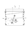
図1〜図16は本発明に係るシート切断装置の一実施形態を示したもので、図1は本発明の一実施形態のシート切断装置の組立状態の斜視図、図2は図1に示したシート切断装置のシート送り機構の上を覆う蓋部を開いた状態の斜視図、図3は図2のB矢視図、図4は図1に示したシート切断装置上のリールスタンドを交換する方法を示す斜視図、図5は一実施形態のシート切断装置において、リールスタンドのシート用リールのシートを使い切った状態を示す斜視図、図6はシートを使い切ったリールスタンドを装置本体から取り外すために、シート送り機構の上を覆う蓋部を開いた状態にしたシート切断装置の斜視図、図7は図6のC矢視図、図8はシートを使い切って装置本体から取り外されたリールスタンドの斜視図、図9は図8のD矢視図、図10はリールスタンドに装備されている第2リール支持部の概略構成を示す拡大図、図11はシート用リールにシートが補充されている予備のリールスタンドの斜視図、図12は図11のE矢視図、図13は予備のリールスタンドを装着するために、シート送り機構の上を覆う蓋部を開いた状態にした装置本体の斜視図、図14は図13に示した装置本体のシート送り機構におけるシート載置面の構造の説明図、図15は図13に示した装置本体の前面側に装備されているシート切断機構の説明図、図16は一実施形態のシート切断装置におけるシート及び離型紙の走行経路を示す概略図である。 1 to 16 show an embodiment of a sheet cutting apparatus according to the present invention. FIG. 1 is a perspective view of an assembled state of the sheet cutting apparatus according to an embodiment of the present invention. FIG. FIG. 3 is a perspective view showing a state in which a cover portion covering the sheet feeding mechanism of the sheet cutting device is opened, FIG. 3 is a view as viewed from an arrow B in FIG. 2, and FIG. 4 is a replacement of the reel stand on the sheet cutting device shown in FIG. FIG. 5 is a perspective view showing a state where a sheet of a reel for a reel stand is used up in a sheet cutting apparatus according to an embodiment, and FIG. FIG. 7 is a perspective view of the sheet cutting device with the lid covering the sheet feeding mechanism opened, FIG. 7 is a view as viewed from the direction of arrow C in FIG. 6, and FIG. FIG. 9 is a perspective view of the stand, FIG. FIG. 10 is an enlarged view showing a schematic configuration of a second reel support portion mounted on the reel stand, FIG. 11 is a perspective view of a spare reel stand in which a sheet reel is replenished, FIG. 11 is a perspective view of the apparatus main body with the lid covering the sheet feeding mechanism opened to mount a spare reel stand. FIG. 14 is a perspective view of FIG. 15 is an explanatory view of the structure of the sheet placing surface in the sheet feeding mechanism of the apparatus main body, FIG. 15 is an explanatory view of the sheet cutting mechanism provided on the front side of the apparatus main body shown in FIG. 13, and FIG. It is the schematic which shows the driving | running route of the sheet | seat and release paper in a sheet cutting device.
この一実施形態のシート切断装置1は、図17に示したシート110を所定の長さに切断する装置である。
The
シート110は、図17に示すように、ビニール製のシート本体111の片面の一側縁に沿って粘着層112が形成されると共に、粘着層112には離型紙113が貼付された帯状のシートである。
As shown in FIG. 17, the
本実施形態のシート切断装置1は、図1〜図4に示すように、シート用リール4と、離型紙用リール5と、リールスタンド6と、装置本体7と、を備える。また、リールスタンド6は、予備の分も用意される。
As shown in FIGS. 1 to 4, the
シート用リール4は、図4に示すように、リール軸41と、該リール軸41の両端に接続された一対のフランジ42と、後述するリールスタンド6に支持される一対のスタンド取付部43と、を備えている。シート用リール4は、図1に示すように、リール軸41の外周に、長尺のシート110が巻回される。
As shown in FIG. 4, the
一対のスタンド取付部43は、一対のフランジ42の外面側に、リール軸41と同軸に装備されている。一対のスタンド取付部43は、リール軸41を回転自在に支持している。一対のスタンド取付部43は、その角形の軸部43aを、後述のリールスタンド6の一対の側壁部61,62に装備された第1リール支持部63に係合させることで、一対の側壁部61,62に回転不可に結合される。本実施形態の場合、第1リール支持部63は、上方に開放した切り欠き孔で、上方から軸部43aを割り込ませることで、シート用リール4を支持する。本実施形態の場合、第1リール支持部63は、一対のスタンド取付部43を介して、リール軸41を回転自在に支持している。
The pair of
本実施形態の場合、リール軸41は、図7に示すように、長手方向に適宜間隔を開けて、複数のフランジ取付孔41aを有している。これらのフランジ取付孔41aは、フランジ42をリール軸41に結合するための孔で、使用するフランジ取付孔41aを変更することで、一対のフランジ42の間隔を調整することができる。一対のフランジ42の間隔は、リール軸41に巻回させるシート110の幅に合うように、調整することができる。
In the case of this embodiment, the
離型紙用リール5は、シート110から剥離させた離型紙113を巻き取るためのリールである。離型紙用リール5は、図4に示すように、シート110上の離型紙113の位置と対応するように、後述するリールスタンド6の片側の側壁部62に回転自在に取り付けられる。
The
リールスタンド6は、図4及び図8及び図9に示すように、シート用リール4のリール軸41の軸方向に対向して配置された一対の側壁部61,62と、シート用リール4を回転可能に支持する第1リール支持部63と、離型紙用リール5を回転可能に支持する第2リール支持部64と、シート先端支持部材65と、一対の側壁部61,62の底部(下部)を結合している2本の位置決め用ロッド66a,66bと、一対の側壁部61,62の高さ方向の中間部を結合している一対の連結用ロッド67a,67bと、複数の離型紙経路設定部材68aと、を備えている。
As shown in FIGS. 4, 8, and 9, the
本実施形態の場合、一対の側壁部61,62は、図4に示すように、一対の側壁部61,62の底部(下部)を相互結合する2本の位置決め用ロッド66a,66bと、一対の側壁部61,62の高さ方向の中間部を相互結合する一対の連結用ロッド67a,67bとで、所定の間隔に結合されている。
In the case of this embodiment, as shown in FIG. 4, the pair of
また、一対の側壁部61,62には、図9に示すように、当該リールスタンド6を搬送するときの把持部となる取っ手611が固定装備されている。
Further, as shown in FIG. 9, a pair of
第1リール支持部63は、本実施形態の場合、前述したように、シート用リール4のスタンド取付部43の軸部43aが係合する切り欠き孔で、一対のスタンド取付部43を介して、リール軸41を回転自在に支持している。
In the case of this embodiment, the first
第2リール支持部64は、図4及び図9に示すように、リールスタンド6の片側の側壁部62に装備されている。
As shown in FIGS. 4 and 9, the second
本実施形態における第2リール支持部64は、図10に示すように、離型紙用リール5の中心を挿通して離型紙用リール5と一体に回転する第2リール支持軸641と、該第2リール支持軸641の一端を回転自在に支持する軸受け部642と、軸受け部642に支持された第2リール支持軸641を軸方向(図10(b)の矢印A1方向)に移動させる軸移動機構643と、を備えている。
As shown in FIG. 10, the second
軸移動機構643は、図10に示すように、側壁部62に突設されたリブ643aと、第2リール支持軸641の外周に突設されてリブ643aに当接可能な係止突起643bと、第2リール支持軸641を側壁部62の内側(図10(b)の矢印A1の示す側)に移動するように付勢するばね643cと、リブ643a間の谷間643dと、を備えている。
As shown in FIG. 10, the
図10(a)に示すように、係止突起643bがリブ643aに当接している状態では、軸受け部642に支持された第2リール支持軸641の自由端641aは、待機位置P1に位置している。
As shown in FIG. 10A, in a state where the locking
係止突起643bは、図10(b)に矢印M1で示すように、第2リール支持軸641を軸回りに所定角度回転させると、リブ643aから外れて、リブ643a間に装備されている谷間643dに没入可能になる。係止突起643bがリブ643aから外れると、第2リール支持軸641は、図10(b)に示すように、ばね643cの付勢力で、側壁部62の内側に向かって移動し、第2リール支持軸641の自由端641aは、結合位置P2に移動する。結合位置P2は、待機位置P1から軸方向に規定長だけ離間した位置で、後述する装置本体7の離型紙リール駆動軸75と結合状態になる位置である。
As shown by arrow M1 in FIG. 10B, the locking
以上に説明した軸移動機構643は、言い換えると、軸受け部642に支持された第2リール支持軸641の自由端641aを、待機位置P1と該待機位置P1から軸方向に規定長だけ離間した結合位置P2とに、位置切り替え可能にしている。
In other words, the
シート先端支持部材65は、図4及び図9に示すように、リールスタンド6の片側の側壁部62からシート110の繰り出し方向(図9の矢印A3方向)に張り出した梁部651と、この梁部651の基端側からシート110の幅方向に張り出した第1シート位置規制部652と、梁部651の先端からシート110の幅方向に張り出した先端支持部653と、梁部651の中間部からシート110の幅方向に張り出した第2シート位置規制部654と、を備えている。先端支持部653は、図4に示すように、リールスタンド6に取り付けられたシート用リール4から引き出されたシート110の先端を、上下一対の規制部材653a,653bによって保持する。
As shown in FIGS. 4 and 9, the sheet front
本実施形態のシート先端支持部材65は、リールスタンド6の第1リール支持部63に取り付けられたシート用リール4に巻回されている前記シート110の先端側を、第1シート位置規制部652と、第2シート位置規制部654と、先端支持部653と、で、水平に延在させた状態に支持する。
The sheet front
シート先端支持部材65によって水平に延在させた状態に支持されたシート110の先端部は、リールスタンド6を装置本体7に取り付けた際に、装置本体7のシート送り機構72の上に載って、シート送り機構72に接触し、シート送り機構72によるシート110の繰り出しが可能になる。即ち、シート先端支持部材65は、支持しているシート110の先端を、シート送り機構72に渡す。
When the
本実施形態の場合、図4に示すように、先端支持部653の下側の規制部材653bは、シート110の粘着層112の出っ張りを逃がす段差部D6が設けられている。この段差部D6は、粘着層112が接触しないように、窪みの深さが設定されている。
In the case of the present embodiment, as shown in FIG. 4, the
一対の側壁部61,62の底部(下部)を結合している2本の位置決め用ロッド66a,66bは、リールスタンド6を装置本体7に組み付けたときに、装置本体7側の位置決め用ブロック76が嵌合する隙間を形成している。
The two
また、図13に示すように、シート送り機構72の側壁723の上面には2つの位置決めピン724が設けられている。一方、シート先端支持部材65の下面の、位置決めピン724に対応する部分のそれぞれには、位置決めピン724と嵌合する位置決め穴655(図9、図12参照)が設けられている。これらの位置決めピン724と位置決め穴655も位置決め機構の一部を構成する。そして、位置決めピン724が位置決め穴655に嵌合することで、シート送り機構72に対するシート先端支持部材65の位置決めが正確に行われる。
Further, as shown in FIG. 13, two positioning
リールスタンド6を装置本体7に位置決めするスタンド位置決め機構は、2本の位置決めロッド66a,66bと、位置決め用ブロック76と、位置決めピン724と、位置決め穴655とで、構成されている。
The stand positioning mechanism for positioning the
複数の離型紙経路設定部材68aは、図4に示すように、側壁部62に突設されたガイドローラで、図16に示すように、シート先端支持部材65に支持されているシート110の先端から剥がして離型紙用リール5に固定された離型紙113の離型紙用リール5に至る経路を規制する。
As shown in FIG. 4, the plurality of release paper
装置本体7は、図4及び図13に示すように、リールスタンド6を着脱可能なスタンド取付部71と、シート送り機構72と、シート送り機構72の上を開閉可能に覆う蓋部73と、シート切断機構74と、離型紙リール駆動軸75(図10参照)と、を備えている。
As shown in FIGS. 4 and 13, the apparatus
スタンド取付部71は、図13に示すように、リールスタンド6を載置する水平な載置面711と、リールスタンド6に載置されるリールスタンド6を位置決めする位置決め用ブロック76と、離型紙切れ検知確認センサ718と、を備えている。
As shown in FIG. 13, the
位置決め用ブロック76は、前述したリールスタンド6の2本の位置決め用ロッド66a,66bとの協働で、リールスタンド6を位置決め用ブロック76上に位置決めするスタンド位置決め機構8を構成する。位置決め用ブロック76は略直方体状のブロックで、2本の位置決め用ロッド66a,66bが形成する隙間の片側66s(図4参照)に略緊密に嵌合することで、リールスタンド6の2方向の位置決めをして、リールスタンド6を正確に位置決めする。
The
言い換えると、本実施形態のシート切断装置1は、スタンド取付部71と前記リールスタンド6との間に、リールスタンド6をスタンド取付部71に取り付ける際に、簡単に且つ正確にリールスタンド6を位置決めすることができてリールスタンド6の交換を容易にするスタンド位置決め機構8を備えたものである。
In other words, the
離型紙切れ検知確認センサ718は、投受光センサを利用したもので、図16に示すように、スタンド取付部71に取り付けられたリールスタンド6上で離型紙用リール5に巻き取られる離型紙113の経路に光を照射して、照射した光の反射の有無により離型紙切れを検知する。
The release paper breakage
図17に示すように、シート110上の粘着層112及び離型紙113は、連続せずに途切れている場合がある。シート110の繰り出し中に、このような離型紙113の途切れた部分があった場合、シート110の繰り出しを停止して、途切れた部分よりも後続の離型紙113を、離型紙用リール5に固定する必要がある。このために、離型紙切れ検知確認センサ718により離型紙113の有無を検知する。
As shown in FIG. 17, the
シート送り機構72は、図13に示したように、蓋部73を開くと、その水平な上面部72aが露出する。また、図14に示すように、シート110の粘着層112と対向する位置には、粘着層112が接触してシート110の搬送に支障が生じないように、上面部72aよりも凹んだ段差部D7が形成されている。この段差部D7は、粘着層112が接触しないように、窪みの深さが設定されている。また、本実施形態では、蓋部73を開いた状態で、スタンド取付部71にリールスタンド6をセットすると、リールスタンド6のシート先端支持部材65に水平に支持されているシート110の下面が、上面部72aに載置された状態になる。また、シート110の粘着層112は、段差部D7の上に張り出している。その状態で、スタンド取付部43を閉じると、シート先端支持部材65に水平に支持されているシート110の下面が、上面部72aに押し付けられる。
As shown in FIG. 13, when the
シート送り機構72の上面部72aには、図13及び図16に示すように、シート110の片面に当接した状態で回転駆動されることでシート110を送り出す送りローラ721と、シート110の片面に当接してシート110の走行に追従して回転する測長用ローラ722と、を備えている。
As shown in FIGS. 13 and 16, the
蓋部73には、図13及び図16に示すように、送りローラ721と対向する位置に配置された押さえローラ731と、測長用ローラ722と対向する位置に配置された押さえローラ732とが備えられている。即ち、蓋部73は、図16に示すように、押さえローラ731,732によってシート110を送りローラ721及び測長用ローラ722に押さえ付けて、各ローラ721,722とシート110との間に滑りが生じることを防止する。
As shown in FIGS. 13 and 16, the
本実施形態のシート送り機構72は、シート110の下面に当接する送りローラ721によって、スタンド取付部71に取り付けられたリールスタンド6上のシート用リール4からシート110を繰り出す。
The
本実施形態のシート切断装置1では、シート送り機構72に装備された測長用ローラ722の回転量からシート110の繰り出し長を算出する演算処理部が装備されていて、測長用ローラ722の回転量からシート110の繰り出し長が検知される。
In the
シート切断機構74は、シート送り機構72の下流側で、図13に示す装置本体7の前面カバー77の内側に配置されている。本実施形態のシート切断機構74は、図15に示すように、カッター刃741と、このカッター刃741を往復動させるクランク機構742と、を備えている。カッター刃741は、シート送り機構72から送り出されるシート110の表面と直交する方向(図15では、矢印A4方向)に進退可能に、前記シート送り機構72の下流側に配置されている。クランク機構742は、測長用ローラ722の回転量に基づいて垂直方向に往復動するクランクロッド742aによって、カッター刃741をシート110の走行位置に進退させて、シート送り機構72により繰り出されるシート110を所定の長さに切断する。
The
離型紙リール駆動軸75は、装置本体7のスタンド取付部71に装備されている。この離型紙リール駆動軸75は、図10(b)に示すように、スタンド取付部71に取り付けられたリールスタンド6上の第2リール支持軸641が結合位置P2に移動したときに第2リール支持軸641の自由端641aと結合状態となる。第2リール支持軸641に結合状態となった離型紙リール駆動軸75は、図示しない駆動機構から伝達される回転力で、第2リール支持軸641を回転駆動可能である。
The release paper
離型紙リール駆動軸75は、シート送り機構72によって送り出されたシート110上の離型紙113が離型紙用リール5に逐次巻き取られるように、シート送り機構72の送りローラ721と連動して、リールスタンド6上の離型紙用リール5を回転駆動する。
The release paper
また、図示はしていないが、本実施形態において離型紙リール駆動軸75を駆動する機構には、離型紙リール駆動軸75の駆動トルクを規定値以内に制限するトルクリミッターが備えられていて、駆動トルクが既定値を超えないように離型紙リール駆動軸75の回転速度が制御される。
Although not shown, the mechanism for driving the release paper
以上に説明した本実施形態のシート切断装置1の場合、リールスタンド6は、装置本体7のスタンド取付部71に取り付けた際には、当該リールスタンド6にセットされているシート用リール4から引き出されたシート110の先端が、シート先端支持部材65によって、装置本体7側のシート送り機構72に渡される。そのため、リールスタンド6を装置本体7のスタンド取付部71に取り付けると、直ぐに、シート110を所定の長さずつ繰り出して切断する作業が可能になる。
In the case of the
また、リールスタンド6は、シート送り機構72が繰り出すシート110の先端から剥がした離型紙113を巻き取る離型紙用リール5を備えている。そして、リールスタンド6に装備されている離型紙用リール5は、リールスタンド6を装置本体7のスタンド取付部71に取り付けると、装置本体7の離型紙リール駆動軸75により駆動可能になり、シート送り機構72によるシート110の繰り出し処理に連動して離型紙113の巻き取りが可能になる。
The
即ち、本実施形態のシート切断装置1によれば、リールスタンド6を装置本体7のスタンド取付部71に取り付けると、直ちに、リールスタンド6上のシート用リール4からシート110を繰り出して所定長に切断する作業や、シート110から剥がした離型紙113を離型紙用リール5に巻き取る作業が可能になる。
That is, according to the
また、スタンド取付部71とリールスタンド6との間には、リールスタンド6をスタンド取付部71に取り付ける際に、簡単に且つ正確にリールスタンド6を位置決めすることができてリールスタンド6の交換を容易にするスタンド位置決め機構8が備えられている。
In addition, when the
従って、本実施形態のシート切断装置1では、予め、シート110を巻回したシート用リール4が組み付けられると共に、シート用リール4から引き出したシート110の先端から剥がした離型紙113を離型紙用リール5に固定した予備のリールスタンド6を用意しておき、リールスタンド6上のシート110を使い切った場合には、シート切断装置1の運転を停止させて、リールスタンド6ごと予備のリールスタンド6と交換すると、交換時に手間のかかる剥離紙誘導作業が不要で、直ちに、シート切断装置1の運転再開が可能になる。
Therefore, in the
従って、シート110を補充する際の作業時間を短縮して、装置の稼働率を高めることができる。
Accordingly, it is possible to shorten the work time when the
また、本実施形態のシート切断装置1では、スタンド位置決め機構8は、リールスタンド6の底部の2本の位置決め用ロッド66a,66bと、スタンド取付部71に突設される略直方体状の位置決め用ブロック76と、で構成される単純な構成である。そして、位置決め用ブロック76と2本の位置決め用ロッド66a,66bとの嵌合精度、及び位置決めピン724と位置決め穴655との嵌合精度を高めることで、リールスタンド6の位置決め精度を向上させることができる。従って、リールスタンド6の高精度な位置決めを、安価に実現することができる。
Further, in the
また、本実施形態のシート切断装置1では、シート110の繰り出し動作の際に、測長用ローラ722の回転量と測長用ローラ722の周長とを積算する単純な演算処理で、シート110の繰り出し長を正確に検知することができ、シート110を所定の長さに切断する処理の信頼性を向上させることができる。
In the
また、本実施形態のシート切断装置1では、リールスタンド6をスタンド取付部71に取り付ける際には、リールスタンド6の軸移動機構643によって、第2リール支持軸641の自由端641aを待機位置P1に位置させておくことで、取り付け時に第2リール支持軸641の自由端641aが装置本体7の離型紙リール駆動軸75に干渉することがなく、安全にリールスタンド6をスタンド取付部71に取り付けることができる。
In the
そして、リールスタンド6をスタンド取付部71に取り付けた後、リールスタンド6の軸移動機構643によって、第2リール支持軸641の自由端641aを結合位置P2に移動させると、第2リール支持軸641が離型紙リール駆動軸75に結合されて、シート110の繰り出し動作に連動する離型紙113の巻き取り動作が可能になる。
Then, after the
即ち、リールスタンド6をスタンド取付部71に取り付けた際に、軸移動機構643によって、第2リール支持軸641の自由端641aを待機位置P1から結合位置P2に切り替えるという簡単な操作を行うだけで、離型紙用リール5による離型紙113の巻き取りが可能になり、リールスタンド6をスタンド取付部71に取り付けた際に必要な操作が簡便で済み、装置の運転再開を早めることができる。
That is, when the
また、本実施形態のシート切断装置1では、離型紙用リール5における離型紙113の巻き径の増大に伴って、離型紙用リール5の一回転当たりの離型紙113の巻き取り長が増大する。そのため、離型紙用リール5を単純に一定回転速度で回転駆動していると、離型紙113の巻き径の増大に伴って巻き取り量が増大して、離型紙113が過大な張力で破断したり、剥離紙の無理な引っ張りによってシート110の送り出しに支障が生じるおそれがある。しかし、また、本実施形態のシート切断装置1では、駆動トルクが既定値を超えないように、離型紙リール駆動軸75の回転速度がトルクリミッターによって制御されるため、離型紙113の巻き径が増大しても、離型紙113の破断やシート110の送り出しに支障が生じることを防止することができ、シート110の繰り出し動作や離型紙113の巻き取り動作の信頼性を向上させることができる。
Further, in the
また、本実施形態のシート切断装置1では、シート110の繰り出し長が所定の長さに達する度に、カッター刃741をシート110の走行位置に進出させて、シート110を所定の長さに切断することができる。
Further, in the
また、本実施形態のシート切断装置1では、リールスタンド6上の離型紙用リール5に巻き取られる離型紙113は、離型紙経路設定部材68aによって離型紙用リール5に至る経路が設定されている。そのため、離型紙経路設定部材68aによって設定されている経路に光を照射すると、離型紙113が経路に残っている場合には、照射した光が所定位置に反射される。従って、反射光の有無によって、離型紙113の切れを確実に検知することができる。
In the
なお、本発明は、上述した実施形態に限定されるものではなく、適宜、変形、改良、等が可能である。その他、上述した実施形態における各構成要素の材質、形状、寸法、数、配置箇所、等は本発明を達成できるものであれば任意であり、限定されない。
例えば、本発明の切断対象となるシートは、ビニールシートに限らない。
In addition, this invention is not limited to embodiment mentioned above, A deformation | transformation, improvement, etc. are possible suitably. In addition, the material, shape, dimensions, number, arrangement location, and the like of each component in the above-described embodiment are arbitrary and are not limited as long as the present invention can be achieved.
For example, the sheet to be cut according to the present invention is not limited to a vinyl sheet.
ここで、上述した本発明に係るシート切断装置の実施形態の特徴をそれぞれ以下[1]〜[7]に簡潔に纏めて列記する。 Here, the features of the embodiment of the sheet cutting apparatus according to the present invention described above are briefly summarized and listed in the following [1] to [7], respectively.
[1] 片面の一側縁に沿って粘着層(112)が形成されると共に前記粘着層(112)には離型紙(113)が貼付された帯状のシート(110)を巻回したシート用リール(4)と、
前記シート(110)から剥離した前記離型紙(113)を巻き取るための離型紙用リール(5)と、
前記シート用リール(4)を回転可能に支持する第1リール支持部(63)と、前記離型紙用リール(5)を回転可能に支持する第2リール支持部(64)と、を有するリールスタンド(6)と、
前記リールスタンド(6)を着脱可能なスタンド取付部(71)と、該スタンド取付部(71)に取り付けられた前記リールスタンド(6)上の前記シート用リール(4)から前記シート(110)を繰り出すシート送り機構(72)と、前記シート送り機構(72)により繰り出される前記シート(110)を所定の長さに切断するシート切断機構(74)と、前記シート送り機構(72)によって送り出された前記シート(110)上の前記離型紙(113)が前記離型紙用リール(5)に逐次巻き取られるように前記シート送り機構(72)に連動して前記リールスタンド(6)上の前記離型紙用リール(5)を回転駆動する離型紙リール駆動軸(75)と、を具備した装置本体(7)と、
を備えるシート切断装置(1)であって、
前記リールスタンド(6)は、前記第1リール支持部(63)に取り付けられた前記シート用リール(4)に巻回されている前記シート(110)の先端を支持すると共に前記リールスタンド(6)を前記スタンド取付部(71)に取り付けた際に支持している前記シート(110)の先端を前記シート送り機構(72)に渡すシート先端支持部材(65)を備え、
前記スタンド取付部(71)と前記リールスタンド(6)との間には、前記リールスタンド(6)を前記スタンド取付部(71)に取り付ける際に、簡単に且つ正確に前記リールスタンド(6)を位置決めすることができて前記リールスタンド(6)の交換を容易にするスタンド位置決め機構(8)を備えたことを特徴とするシート切断装置(1)。
[1] For a sheet in which an adhesive layer (112) is formed along one side edge of one side and a belt-like sheet (110) having a release paper (113) attached thereto is wound around the adhesive layer (112) Reel (4),
A release paper reel (5) for winding up the release paper (113) peeled from the sheet (110);
A reel having a first reel support portion (63) for rotatably supporting the sheet reel (4) and a second reel support portion (64) for rotatably supporting the release paper reel (5). A stand (6);
A stand mounting portion (71) to which the reel stand (6) can be attached and detached, and the seat (110) from the sheet reel (4) on the reel stand (6) attached to the stand mounting portion (71). The sheet feeding mechanism (72) for feeding the sheet, the sheet cutting mechanism (74) for cutting the sheet (110) fed by the sheet feeding mechanism (72) to a predetermined length, and the sheet feeding mechanism (72). The reel paper (113) on the reel (5) is interlocked with the sheet feed mechanism (72) so that the release paper (113) on the sheet (110) is sequentially wound on the reel for release paper (5). An apparatus body (7) comprising a release paper reel drive shaft (75) for rotationally driving the release paper reel (5);
A sheet cutting device (1) comprising:
The reel stand (6) supports the front end of the sheet (110) wound around the sheet reel (4) attached to the first reel support portion (63), and also supports the reel stand (6). ) Is provided with a sheet front end support member (65) that passes the front end of the sheet (110) supported when the stand is attached to the stand mounting portion (71) to the sheet feeding mechanism (72),
When the reel stand (6) is attached to the stand attachment portion (71) between the stand attachment portion (71) and the reel stand (6), the reel stand (6) is easily and accurately attached. The sheet cutting device (1) is provided with a stand positioning mechanism (8) that can position the reel stand (6) and facilitate replacement of the reel stand (6).
[2] 前記スタンド位置決め機構(8)は、前記リールスタンド(6)の底部に架設された2本の位置決め用ロッド(66a,66b)と、前記スタンド取付部(71)に突設されて前記リールスタンド(6)を前記スタンド取付部(71)に載せたときに前記2本の位置決め用ロッド(66a,66b)が形成する隙間の片側に嵌合する略直方体状の位置決め用ブロック(76)と、
前記シート送り機構(72)に設けられた位置決めピン(724)と、前記シート先端支持部材(65)に設けられた位置決め穴(655)と、
を備え
2本の前記位置決め用ロッド(66a,66b)間への前記位置決め用ブロック(76)の嵌合、及び前記位置決めピン(724)と前記位置決め穴(655)との嵌合によって、前記リールスタンド(6)を位置決めすることを特徴とする上記[1]に記載のシート切断装置(1)。
[2] The stand positioning mechanism (8) protrudes from the two positioning rods (66a, 66b) installed on the bottom of the reel stand (6) and the stand mounting portion (71). A substantially rectangular parallelepiped positioning block (76) that fits on one side of the gap formed by the two positioning rods (66a, 66b) when the reel stand (6) is placed on the stand mounting portion (71). When,
A positioning pin (724) provided in the sheet feeding mechanism (72), a positioning hole (655) provided in the sheet leading end support member (65),
The reel is obtained by fitting the positioning block (76) between the two positioning rods (66a, 66b) and fitting the positioning pin (724) and the positioning hole (655). The sheet cutting device (1) according to the above [1], wherein the stand (6) is positioned.
[3] 前記シート送り機構(72)は、前記シート(110)の片面に当接した状態で回転駆動されることで前記シート(110)を送り出す送りローラ(721)と、前記シート(110)の片面に当接して前記シート(110)の走行に追従して回転する測長用ローラ(722)と、を備え、
前記測長用ローラ(722)の回転量から前記シート(110)の繰り出し長が検知されることを特徴とする上記[1]又は[2]に記載のシート切断装置(1)。
[3] The sheet feeding mechanism (72) is rotationally driven while being in contact with one surface of the sheet (110), thereby feeding the sheet (110), and the sheet (110). A length measuring roller (722) that abuts on one side of the sheet and rotates following the traveling of the sheet (110),
The sheet cutting device (1) according to [1] or [2], wherein a feeding length of the sheet (110) is detected from a rotation amount of the length measuring roller (722).
[4] 前記第2リール支持部(64)は、前記離型紙用リール(5)の中心を挿通して前記離型紙用リール(5)と一体に回転する第2リール支持軸(641)と、該第2リール支持軸(641)の一端を回転自在に支持する軸受け部(642)と、前記軸受け部(642)に支持された前記第2リール支持軸(641)の自由端(641a)を待機位置(P1)と該待機位置(P1)から軸方向に規定長だけ離間した結合位置(P2)とに位置切り替え可能にする軸移動機構(643)と、を備え、
前記装置本体(7)の前記スタンド取付部(71)には、前記スタンド取付部(71)に取り付けられた前記リールスタンド(6)上の前記第2リール支持軸(641)が前記結合位置(P2)に移動したときに前記第2リール支持軸(641)の自由端(641a)と結合状態となって、前記第2リール支持軸(641)を回転駆動可能な離型紙リール駆動軸(75)を備え、
前記離型紙リール駆動軸(75)は、前記送りローラ(721)と連動して駆動される、
ことを特徴とする上記[3]に記載のシート切断装置(1)。
[4] The second reel support portion (64) includes a second reel support shaft (641) that rotates through the center of the release paper reel (5) and rotates integrally with the release paper reel (5). A bearing portion (642) that rotatably supports one end of the second reel support shaft (641), and a free end (641a) of the second reel support shaft (641) supported by the bearing portion (642). A shaft moving mechanism (643) that can switch between a standby position (P1) and a coupling position (P2) that is spaced apart from the standby position (P1) in the axial direction by a specified length,
The second reel supporting shaft (641) on the reel stand (6) attached to the stand attaching portion (71) is connected to the stand attachment portion (71) of the apparatus main body (7) in the coupling position ( A release paper reel drive shaft (75) that is coupled to the free end (641a) of the second reel support shaft (641) when moved to P2) and can rotate the second reel support shaft (641). )
The release paper reel drive shaft (75) is driven in conjunction with the feed roller (721).
The sheet cutting device (1) according to the above [3], which is characterized in that
[5] 前記離型紙リール駆動軸(75)を駆動する機構には、前記離型紙リール駆動軸(75)の駆動トルクを規定値以内に制限するトルクリミッターが備えられていて、駆動トルクが既定値を超えないように前記離型紙リール駆動軸(75)の回転速度が制御されることを特徴とする上記[4]に記載のシート切断装置(1)。 [5] The mechanism for driving the release paper reel drive shaft (75) is provided with a torque limiter for limiting the drive torque of the release paper reel drive shaft (75) to within a specified value. The sheet cutting device (1) according to the above [4], wherein the rotational speed of the release paper reel drive shaft (75) is controlled so as not to exceed the value.
[6] 前記シート切断機構(74)は、前記シート送り機構(72)から送り出される前記シート(110)の表面と直交する方向に進退可能に前記シート送り機構(72)の下流側に配置されたカッター刃(741)と、前記測長用ローラ(722)の回転量に基づいて前記カッター刃(741)を前記シート(110)の走行位置に進退させるクランク機構(742)と、を備えることを特徴とする上記[3]〜[5]の何れかに記載のシート切断装置(1)。 [6] The sheet cutting mechanism (74) is disposed on the downstream side of the sheet feeding mechanism (72) so as to be able to advance and retreat in a direction orthogonal to the surface of the sheet (110) fed from the sheet feeding mechanism (72). And a crank mechanism (742) for moving the cutter blade (741) back and forth to the travel position of the sheet (110) based on the rotation amount of the length measuring roller (722). The sheet cutting device (1) according to any one of [3] to [5] above.
[7] 前記リールスタンド(6)は、前記シート先端支持部材(65)に支持されている前記シート(110)の先端から剥がして前記離型紙用リール(5)に固定された前記離型紙(113)の前記離型紙用リール(5)に至る経路を規制する離型紙経路設定部材(68a)、を備え、
前記装置本体(7)の前記スタンド取付部(71)には、前記スタンド取付部(71)に取り付けられた前記リールスタンド(6)上で前記離型紙用リール(5)に巻き取られる前記離型紙(113)の経路に光を照射して、照射した光の反射の有無により離型紙切れを検知する離型紙切れ検知確認センサ(718)を備えたことを特徴とする上記[1]〜[6]の何れかに記載のシート切断装置(1)。
[7] The reel stand (6) is separated from the front end of the sheet (110) supported by the sheet front end support member (65) and fixed to the release paper reel (5). 113) a release paper path setting member (68a) for restricting the path to the release paper reel (5) of 113),
The stand mounting portion (71) of the apparatus main body (7) has the release reel wound on the release paper reel (5) on the reel stand (6) mounted on the stand mounting portion (71). The above-mentioned [1] to [1], comprising a release paper break detection confirmation sensor (718) for irradiating light to the path of the pattern paper (113) and detecting the release paper breakage by the presence or absence of reflection of the irradiated light. 6] The sheet cutting device (1) according to any one of the above.
1 シート切断装置
4 シート用リール
5 離型紙用リール
6 リールスタンド
7 装置本体
8 スタンド位置決め機構
63 第1リール支持部
64 第2リール支持部
65 シート先端支持部材
66a,66b 位置決め用ロッド
68a 離型紙経路設定部材
71 スタンド取付部
72 シート送り機構
74 シート切断機構
75 離型紙リール駆動軸
76 位置決め用ブロック
110 シート
112 粘着層
113 離型紙
641 第2リール支持軸
641a 自由端
642 軸受け部
643 軸移動機構
718 離型紙切れ検知確認センサ
721 送りローラ
722 測長用ローラ
741 カッター刃
742 クランク機構
P1 待機位置
P2 結合位置
DESCRIPTION OF
Claims (7)
前記シートから剥離した前記離型紙を巻き取るための離型紙用リールと、
前記シート用リールを回転可能に支持する第1リール支持部と、前記離型紙用リールを回転可能に支持する第2リール支持部と、を有するリールスタンドと、
前記リールスタンドを着脱可能なスタンド取付部と、該スタンド取付部に取り付けられた前記リールスタンド上の前記シート用リールから前記シートを繰り出すシート送り機構と、前記シート送り機構により繰り出される前記シートを所定の長さに切断するシート切断機構と、前記シート送り機構によって送り出された前記シート上の前記離型紙が前記離型紙用リールに逐次巻き取られるように前記シート送り機構に連動して前記リールスタンド上の前記離型紙用リールを回転駆動する離型紙リール駆動軸と、を具備した装置本体と、
を備えるシート切断装置であって、
前記リールスタンドは、前記第1リール支持部に取り付けられた前記シート用リールに巻回されている前記シートの先端を支持すると共に前記リールスタンドを前記スタンド取付部に取り付けた際に支持している前記シートの先端を前記シート送り機構に渡すシート先端支持部材を備え、
前記スタンド取付部と前記リールスタンドとの間には、前記リールスタンドを前記スタンド取付部に取り付ける際に、簡単に且つ正確に前記リールスタンドを位置決めすることができて前記リールスタンドの交換を容易にするスタンド位置決め機構を備えたことを特徴とするシート切断装置。 A sheet reel in which a pressure-sensitive adhesive layer is formed along one side edge of one side and a belt-like sheet having a release paper attached thereto is wound on the pressure-sensitive adhesive layer;
A release paper reel for winding up the release paper released from the sheet;
A reel stand comprising: a first reel support portion that rotatably supports the sheet reel; and a second reel support portion that rotatably supports the release paper reel;
A stand mounting portion to which the reel stand can be attached and detached, a sheet feeding mechanism for feeding the sheet from the reel for sheet on the reel stand attached to the stand mounting portion, and the sheet fed by the sheet feeding mechanism A sheet cutting mechanism that cuts the length of the sheet, and the reel stand in conjunction with the sheet feeding mechanism so that the release paper on the sheet fed by the sheet feeding mechanism is sequentially wound on the release paper reel. A release paper reel drive shaft that rotationally drives the release paper reel above, an apparatus main body,
A sheet cutting device comprising:
The reel stand supports a front end of the sheet wound around the reel for the sheet attached to the first reel support portion and supports the reel stand when the reel stand is attached to the stand attachment portion. A sheet leading end support member for passing the leading end of the sheet to the sheet feeding mechanism;
When the reel stand is attached to the stand attachment portion, the reel stand can be easily and accurately positioned between the stand attachment portion and the reel stand, and the reel stand can be easily replaced. A sheet cutting device comprising a stand positioning mechanism.
前記シート送り機構に設けられた位置決めピンと、前記シート先端支持部材に設けられた位置決め穴と、
を備え
2本の前記位置決め用ロッド間への前記位置決め用ブロックの嵌合、及び前記位置決めピンと前記位置決め穴との嵌合によって、前記リールスタンドを位置決めすることを特徴とする請求項1に記載のシート切断装置。 The stand positioning mechanism includes two positioning rods erected on the bottom of the reel stand, and the two positioning rods when the reel stand is placed on the stand mounting portion so as to protrude from the stand mounting portion. A substantially rectangular parallelepiped positioning block that fits on one side of the gap formed by the rod for use;
A positioning pin provided in the sheet feeding mechanism, a positioning hole provided in the sheet leading end support member,
The reel stand is positioned by fitting the positioning block between two positioning rods and fitting the positioning pin and the positioning hole. Sheet cutting device.
前記測長用ローラの回転量から前記シートの繰り出し長が検知されることを特徴とする請求項1又は2に記載のシート切断装置。 The sheet feeding mechanism is rotated while being in contact with one side of the sheet, and a length measuring roller that rotates and follows the running of the sheet by contacting the one side of the sheet and feeding the sheet. And a roller for
The sheet cutting device according to claim 1, wherein a feeding length of the sheet is detected from a rotation amount of the length measuring roller.
前記装置本体の前記スタンド取付部には、前記スタンド取付部に取り付けられた前記リールスタンド上の前記第2リール支持軸が前記結合位置に移動したときに前記第2リール支持軸の自由端と結合状態となって、前記第2リール支持軸を回転駆動可能な離型紙リール駆動軸を備え、
前記離型紙リール駆動軸は、前記送りローラと連動して駆動される、
ことを特徴とする請求項3に記載のシート切断装置。 The second reel support portion rotatably supports one end of the second reel support shaft, and a second reel support shaft that rotates through the center of the release paper reel and rotates integrally with the release paper reel. A shaft moving mechanism that makes it possible to switch the position of the free end of the second reel support shaft supported by the bearing portion between a standby position and a coupling position that is spaced apart from the standby position by a specified length in the axial direction; With
The stand attachment portion of the apparatus main body is coupled to the free end of the second reel support shaft when the second reel support shaft on the reel stand attached to the stand attachment portion moves to the coupling position. A release paper reel drive shaft capable of rotating and driving the second reel support shaft,
The release paper reel drive shaft is driven in conjunction with the feed roller;
The sheet cutting device according to claim 3.
前記装置本体の前記スタンド取付部には、前記スタンド取付部に取り付けられた前記リールスタンド上で前記離型紙用リールに巻き取られる前記離型紙の経路に光を照射して、照射した光の反射の有無により離型紙切れを検知する離型紙切れ検知確認センサを備えたことを特徴とする請求項1〜6の何れか一項に記載のシート切断装置。 The reel stand is configured to set a release paper path that regulates a path of the release paper that is peeled off from the front end of the sheet supported by the sheet front end support member and fixed to the release paper reel to the release paper reel. A member,
The stand mounting portion of the apparatus main body irradiates light onto the path of the release paper wound around the release paper reel on the reel stand attached to the stand mounting portion, and reflects the irradiated light The sheet cutting device according to any one of claims 1 to 6, further comprising a release paper breakage detection confirmation sensor that detects a release paper breakage depending on the presence or absence of the release sheet.
Priority Applications (2)
| Application Number | Priority Date | Filing Date | Title |
|---|---|---|---|
| JP2013153746A JP6130258B2 (en) | 2013-07-24 | 2013-07-24 | Sheet cutting device |
| CN201410356601.6A CN104340738B (en) | 2013-07-24 | 2014-07-24 | Sheet cutting apparatus |
Applications Claiming Priority (1)
| Application Number | Priority Date | Filing Date | Title |
|---|---|---|---|
| JP2013153746A JP6130258B2 (en) | 2013-07-24 | 2013-07-24 | Sheet cutting device |
Publications (2)
| Publication Number | Publication Date |
|---|---|
| JP2015024874A JP2015024874A (en) | 2015-02-05 |
| JP6130258B2 true JP6130258B2 (en) | 2017-05-17 |
Family
ID=52489862
Family Applications (1)
| Application Number | Title | Priority Date | Filing Date |
|---|---|---|---|
| JP2013153746A Active JP6130258B2 (en) | 2013-07-24 | 2013-07-24 | Sheet cutting device |
Country Status (2)
| Country | Link |
|---|---|
| JP (1) | JP6130258B2 (en) |
| CN (1) | CN104340738B (en) |
Families Citing this family (3)
| Publication number | Priority date | Publication date | Assignee | Title |
|---|---|---|---|---|
| CN105171795B (en) * | 2015-08-26 | 2017-05-31 | 江苏苏美达创意家纺实业有限公司 | A kind of efficient automatic cutter |
| CN109015855B (en) * | 2018-09-08 | 2023-11-03 | 东莞卡特威机械科技有限公司 | Sweat-absorbing area oblique angle guillootine |
| CN110973965B (en) * | 2019-12-03 | 2021-06-01 | 赣州东峰自动化设备有限公司 | Automatic feeding and winding device for simulated christmas tree leaves |
Family Cites Families (9)
| Publication number | Priority date | Publication date | Assignee | Title |
|---|---|---|---|---|
| JPS501208B1 (en) * | 1970-01-16 | 1975-01-16 | ||
| JPS59201796A (en) * | 1983-04-30 | 1984-11-15 | 富士ゼロックス株式会社 | Automatic cutter for tape of binder |
| JPH06340135A (en) * | 1993-06-01 | 1994-12-13 | Casio Comput Co Ltd | Tape cassette mounting device |
| JPH0891680A (en) * | 1994-09-20 | 1996-04-09 | Hitachi Ltd | Double-tape holder |
| US6302177B1 (en) * | 1999-08-13 | 2001-10-16 | George Gruber | Tape dispenser system |
| JP4326880B2 (en) * | 2003-08-25 | 2009-09-09 | 株式会社はくぶん | Tape cutter |
| KR100742759B1 (en) * | 2006-05-24 | 2007-07-25 | 류기제 | A cartridge for a edible film dispenser |
| JP2009214433A (en) * | 2008-03-11 | 2009-09-24 | Brother Ind Ltd | Tape cassette |
| JP5184230B2 (en) * | 2008-07-02 | 2013-04-17 | デクセリアルズ株式会社 | Tape cutter device and film laminating method using the same |
-
2013
- 2013-07-24 JP JP2013153746A patent/JP6130258B2/en active Active
-
2014
- 2014-07-24 CN CN201410356601.6A patent/CN104340738B/en active Active
Also Published As
| Publication number | Publication date |
|---|---|
| JP2015024874A (en) | 2015-02-05 |
| CN104340738A (en) | 2015-02-11 |
| CN104340738B (en) | 2016-10-26 |
Similar Documents
| Publication | Publication Date | Title |
|---|---|---|
| US10183510B2 (en) | Guide device for guiding a printed medium onto a take-up roll in a printing system | |
| CN103568598A (en) | Sheet cartridge, label creation apparatus, and control method for label creation apparatus | |
| US9001169B2 (en) | Printer and recording medium | |
| JP6130258B2 (en) | Sheet cutting device | |
| JP5619844B2 (en) | Sheet feeding device | |
| JP5658856B2 (en) | Paper splicing method and apparatus enabling pattern matching | |
| RU2758011C2 (en) | Method and device for feeding and splicing sheet of material wound in roll | |
| US20130175418A1 (en) | Mounting system for label dispensing unit | |
| US10017345B2 (en) | Device for cutting film-like media | |
| JP2001180055A (en) | Method for setting paper roll and printing apparatus | |
| JP6445592B2 (en) | Carrier tape cutting device, cutting method, and carrier tape supply method | |
| JP2015076466A (en) | Automatic splicing device, feeding device equipped with the same, and cassette type tape holding tool | |
| JP6613613B2 (en) | Automatic wallpaper pasting machine | |
| US9623687B2 (en) | Roll paper conveyance control method, roll paper conveyance device, and printer | |
| JP7048306B2 (en) | Automatic wallpaper gluing machine using wallpaper cutting tape | |
| JP7114237B2 (en) | Wallpaper cutting tape, automatic wallpaper gluing machine using wallpaper cutting tape, and control method for automatic wallpaper gluing machine | |
| JP6825814B2 (en) | Sheet piece feeder | |
| JP2013010288A (en) | Method of controlling drive device, the drive device including the same, and tape printing device | |
| NL2023725B1 (en) | A Method of Transporting a Media Web | |
| JP6294630B2 (en) | Test tube sealing device | |
| JP7096005B2 (en) | Tape winder | |
| JP2009143080A (en) | Device for sticking tape | |
| JP2015223695A (en) | Printer | |
| JP5273365B2 (en) | Recording device | |
| JP2023060412A (en) | Carrier tape roll body manufacturing device, parts feeder, component mounting system, and carrier tape roll manufacturing method |
Legal Events
| Date | Code | Title | Description |
|---|---|---|---|
| RD02 | Notification of acceptance of power of attorney |
Free format text: JAPANESE INTERMEDIATE CODE: A7422 Effective date: 20150122 |
|
| A621 | Written request for application examination |
Free format text: JAPANESE INTERMEDIATE CODE: A621 Effective date: 20160617 |
|
| A977 | Report on retrieval |
Free format text: JAPANESE INTERMEDIATE CODE: A971007 Effective date: 20170307 |
|
| TRDD | Decision of grant or rejection written | ||
| A01 | Written decision to grant a patent or to grant a registration (utility model) |
Free format text: JAPANESE INTERMEDIATE CODE: A01 Effective date: 20170314 |
|
| A61 | First payment of annual fees (during grant procedure) |
Free format text: JAPANESE INTERMEDIATE CODE: A61 Effective date: 20170413 |
|
| R150 | Certificate of patent or registration of utility model |
Ref document number: 6130258 Country of ref document: JP Free format text: JAPANESE INTERMEDIATE CODE: R150 |
|
| R250 | Receipt of annual fees |
Free format text: JAPANESE INTERMEDIATE CODE: R250 |
|
| R250 | Receipt of annual fees |
Free format text: JAPANESE INTERMEDIATE CODE: R250 |
|
| R250 | Receipt of annual fees |
Free format text: JAPANESE INTERMEDIATE CODE: R250 |
|
| R250 | Receipt of annual fees |
Free format text: JAPANESE INTERMEDIATE CODE: R250 |
|
| S531 | Written request for registration of change of domicile |
Free format text: JAPANESE INTERMEDIATE CODE: R313531 |
|
| R350 | Written notification of registration of transfer |
Free format text: JAPANESE INTERMEDIATE CODE: R350 |
|
| R250 | Receipt of annual fees |
Free format text: JAPANESE INTERMEDIATE CODE: R250 |