JP6120762B2 - Image processing device - Google Patents
Image processing device Download PDFInfo
- Publication number
- JP6120762B2 JP6120762B2 JP2013258657A JP2013258657A JP6120762B2 JP 6120762 B2 JP6120762 B2 JP 6120762B2 JP 2013258657 A JP2013258657 A JP 2013258657A JP 2013258657 A JP2013258657 A JP 2013258657A JP 6120762 B2 JP6120762 B2 JP 6120762B2
- Authority
- JP
- Japan
- Prior art keywords
- image
- display
- specific image
- specific
- unit
- Prior art date
- Legal status (The legal status is an assumption and is not a legal conclusion. Google has not performed a legal analysis and makes no representation as to the accuracy of the status listed.)
- Active
Links
Images


Description
本発明は、カプセル型内視鏡等の医療用画像取得装置を用いた検査により取得された画像を処理する画像処理装置に関する。 The present invention relates to an image processing apparatus that processes an image acquired by an examination using a medical image acquisition apparatus such as a capsule endoscope.
近年、内視鏡の分野では、患者等の被検体内に導入されて該被検体内を撮像するカプセル型内視鏡を用いた検査が知られている。カプセル型内視鏡は、被検体の消化管内に導入可能な大きさに形成されたカプセル形状の筐体内に撮像機能や無線通信機能等を内蔵した装置であり、被検体内を撮像することにより画像データを生成して、被検体外に順次無線送信する。カプセル型内視鏡から無線送信された画像データは、被検体外に設けられた受信装置に一旦蓄積され、受信装置からワークステーション等の画像処理装置に転送される。画像処理装置において、取得した画像データに対して種々の画像処理を施すことにより、被検体内の臓器等が写った一連の画像が生成される。 In recent years, in the field of endoscopes, examination using a capsule endoscope that is introduced into a subject such as a patient and images the inside of the subject is known. A capsule endoscope is a device that incorporates an imaging function, a wireless communication function, etc. in a capsule-shaped casing that is sized to be introduced into the digestive tract of a subject. Image data is generated and wirelessly transmitted sequentially outside the subject. Image data wirelessly transmitted from the capsule endoscope is temporarily stored in a receiving apparatus provided outside the subject, and transferred from the receiving apparatus to an image processing apparatus such as a workstation. In the image processing apparatus, various image processing is performed on the acquired image data, thereby generating a series of images showing an organ or the like in the subject.
ところで、カプセル型内視鏡は、消化管の蠕動運動により受動的に移動するため、移動速度は非常に不安定である。即ち、消化管内をスムーズに通過することもあれば、消化管自体の構造や消化管内の残留物等に移動を阻害されて、しばらくの間、同じ箇所に滞留することもある。また、滞留していたカプセル型内視鏡が突然、素早く動きだすこともある。 By the way, since the capsule endoscope is passively moved by the peristaltic movement of the digestive tract, the moving speed is very unstable. That is, the gastrointestinal tract may pass smoothly through the gastrointestinal tract, or may stay in the same place for a while because the movement is hindered by the structure of the gastrointestinal tract itself and the residues in the gastrointestinal tract. In addition, the capsule endoscope that has stayed may suddenly move quickly.
一方、消化管内の構造は複雑であるため、カプセル型内視鏡の位置や向きが少しでも変わると、カプセル型内視鏡の撮像結果は全く違ったものとなることが多い。 On the other hand, since the structure in the digestive tract is complicated, if the position and orientation of the capsule endoscope changes even a little, the imaging result of the capsule endoscope is often quite different.
複数の画像の表示に関連する技術として、特許文献1には、画像群における特徴画像を表示させる場合に、特徴画像が表示されることを知らせる通知音を出力する技術が開示されている。また、特許文献2には、フレーム間の画像の変化が設定値以上である場合に、その旨をユーザに通知する技術が開示されている。
As a technique related to the display of a plurality of images,
このような事情から、カプセル型内視鏡により取得された画像を連続的に再生表示すると、視野の突然の変化により画像内の様子が急激に変化する、或いは、病変等の注目すべき領域が突然表示されるといったことが繰り返し発生する。そのため、ユーザ(画像の観察者)は、画像から得られる情報の突然の変化に備えるため、常に画面を注視し続ける必要があり、負担が非常に大きかった。 For these reasons, when the images acquired by the capsule endoscope are continuously reproduced and displayed, the appearance in the image changes suddenly due to a sudden change in the field of view, or there are notable areas such as lesions. A sudden display occurs repeatedly. Therefore, in order to prepare for a sudden change in information obtained from an image, a user (an image observer) needs to keep an eye on the screen at all times, and the burden is very large.
上記問題に関し、特許文献2においては、画面にテキストメッセージを表示することにより、ユーザへの通知を行っている。しかしながら、カプセル型内視鏡により取得された画像内で発生し得る情報の変化は1種類ではないため、情報の変化に応じた通知がなされることが好ましい。この点に関し、テキストメッセージであれば情報の変化に応じた通知は可能であるが、この場合、ユーザはテキストメッセージが表示されるたびに視点を移してメッセージを読まなくてはならず、画像に対する注意が低下してしまうおそれがある。 Regarding the above problem, in Patent Document 2, the user is notified by displaying a text message on the screen. However, since there is not one type of information change that can occur in an image acquired by a capsule endoscope, it is preferable that notification is made according to the information change. In this regard, a text message can be notified in accordance with changes in information. In this case, however, the user must read the message while changing the viewpoint each time the text message is displayed. Attention may be reduced.
本発明は、上記に鑑みてなされたものであって、ユーザが過剰な負担を感じることなく、画像から得られる情報の種々の突然の変化に対して備えることを可能にする画像処理装置を提供することを目的とする。 The present invention has been made in view of the above, and provides an image processing apparatus that enables a user to prepare for various sudden changes in information obtained from an image without feeling an excessive burden. The purpose is to do.
上述した課題を解決し、目的を達成するために、本発明に係る画像処理装置は、時系列順に並べられた画像群に対応する画像データを記憶する記憶部と、前記画像群から、所定の特徴を有する画像を特定画像として特定する画像特定部と、前記画像群に含まれる各画像を表示する表示部と、前記各画像に対応する画像データを前記記憶部から時系列順又は時系列の逆順に取得し、画像データを取得した順に画像を前記表示部に表示させる表示制御部と、前記表示制御部が画像データを取得した表示対象の画像から、該表示対象の画像に対して表示順序が所定枚数後又は表示時刻が所定時間後の画像までの範囲に、前記画像特定部により特定された特定画像が含まれるか否かを判定する判定部と、前記範囲に前記特定画像が含まれると判定された場合に、特定画像が存在する旨の情報を表す表示データを生成する表示データ生成部と、を備え、前記表示制御部は、前記表示対象の画像を含む画面を作成すると共に、前記表示データに基づき、前記特定画像が存在する旨の情報を、前記範囲に含まれる前記特定画像の特性に応じた態様で前記画面に配置することを特徴とする。 In order to solve the above-described problems and achieve the object, an image processing apparatus according to the present invention includes a storage unit that stores image data corresponding to an image group arranged in time series, and a predetermined amount from the image group. An image specifying unit that specifies an image having features as a specific image, a display unit that displays each image included in the image group, and image data corresponding to each image from the storage unit in time series or time series A display control unit that acquires the image data in reverse order and displays the images on the display unit in the order in which the image data was acquired, and a display order for the display target image from the display target image from which the display control unit has acquired the image data Includes a determination unit that determines whether the specific image specified by the image specifying unit is included in a range up to an image after a predetermined number of images or a display time is after a predetermined time, and the specific image is included in the range Determined A display data generation unit that generates display data representing information indicating that the specific image exists, and the display control unit creates a screen including the display target image and adds the display data to the display data. Based on this, information indicating that the specific image exists is arranged on the screen in a manner corresponding to the characteristics of the specific image included in the range.
上記画像処理装置において、前記範囲に含まれる前記特定画像の特性は、前記表示対象の画像から該特定画像までの画像の枚数若しくは表示時間、該特定画像が有する所定の特徴の種類、又は、該特定画像が有する所定の特徴の特徴量の大きさであることを特徴とする。 In the image processing apparatus, the characteristics of the specific image included in the range include the number of images or the display time from the display target image to the specific image, the type of a predetermined feature of the specific image, or the It is a feature amount of a predetermined feature of the specific image.
上記画像処理装置において、前記特定画像が存在する旨の情報は、前記表示対象の画像の周囲に設けられた表示枠であることを特徴とする。 In the image processing apparatus, the information indicating that the specific image exists is a display frame provided around the display target image.
上記画像処理装置において、前記表示制御部は、前記範囲に含まれる前記特定画像の特性に応じて前記表示枠の色調と点滅周期との少なくとも一方を変化させることを特徴とする。 In the image processing apparatus, the display control unit changes at least one of a color tone and a blinking cycle of the display frame according to characteristics of the specific image included in the range.
上記画像処理装置において、前記特定画像が有する前記所定の特徴が、該特定画像内に存在する所定の特徴部である場合、前記画像特定部は、さらに、前記特定画像における前記特徴部の存在領域を特定し、前記表示制御部は、さらに、前記範囲に含まれる前記特定画像における前記特徴部の存在領域に応じて、前記特定画像が存在する旨の情報の前記画面における配置を決定することを特徴とする。 In the image processing device, when the predetermined feature included in the specific image is a predetermined feature existing in the specific image, the image specifying unit further includes an existence region of the characteristic portion in the specific image. The display control unit further determines the arrangement of the information indicating that the specific image exists on the screen according to the existence area of the characteristic part in the specific image included in the range. Features.
上記画像処理装置において、前記特定画像が存在する旨の情報は、前記表示対象の画像の周囲の一部に設けられる部分的な表示枠であることを特徴とする。 In the image processing apparatus, the information indicating that the specific image exists is a partial display frame provided in a part of the periphery of the display target image.
上記画像処理装置において、前記特定画像が存在する旨の情報は、前記表示対象の画像の近傍に配置されるアイコンであり、前記表示制御部は、前記範囲に含まれる前記特定画像の特性に応じて、前記アイコンのサイズ、前記アイコンの表示位置、及び前記アイコンの点滅周期のうちの少なくとも1つを変化させることを特徴とする。 In the image processing apparatus, the information indicating that the specific image exists is an icon arranged in the vicinity of the image to be displayed, and the display control unit responds to characteristics of the specific image included in the range. Then, at least one of the size of the icon, the display position of the icon, and the blinking cycle of the icon is changed.
上記画像処理装置において、前記特定画像が存在する旨の情報は、前記画面に配置される入力用のアイコンであり、外部からの操作に応じた信号を入力する入力部と、前記画面において前記入力用のアイコンを選択する操作に応じた信号が前記入力部から入力された場合に、前記表示部に表示させる画像を前記特定画像にスキップさせるスキップ部と、をさらに備えることを特徴とする。 In the image processing apparatus, the information indicating that the specific image exists is an input icon arranged on the screen, an input unit that inputs a signal according to an operation from the outside, and the input on the screen And a skip unit for skipping an image to be displayed on the display unit to the specific image when a signal corresponding to an operation for selecting an icon is input from the input unit.
上記画像処理装置において、前記画像群は、被検体内に導入されたカプセル型内視鏡が該被検体内を順次撮像することにより取得された一連の画像を含み、前記特定画像は、画像内の所定の特徴量が所定の範囲内である画像、所定の特徴部が検出された画像、画像番号が隣接する画像との類似度が所定値以下である画像、特定の位置若しくは領域が写った画像、又は、当該画像が撮像された際の前記カプセル型内視鏡の速度変化が所定値以上である画像であることを特徴とする。 In the image processing apparatus, the image group includes a series of images acquired by a capsule endoscope introduced into the subject sequentially capturing an image of the subject, and the specific image An image in which a predetermined feature amount is within a predetermined range, an image in which a predetermined feature portion is detected, an image having a similarity with an image having an image number adjacent to a predetermined value, or a specific position or region It is an image or an image in which the speed change of the capsule endoscope when the image is captured is a predetermined value or more.
本発明によれば、表示対象の画像から、該表示対象の画像に対して表示順序が所定枚数後又は表示時刻が所定時間後の画像までの範囲に特定画像が含まれると判定された場合に、特定画像が存在する旨の表示を該特定画像の特性に応じた態様で画面に配置するので、ユーザは、過剰な負担を感じることなく、画像から得られる情報の種々の突然の変化に対して備えることができる。 According to the present invention, when it is determined that the specific image is included in the range from the display target image to the image after the predetermined number of display orders or the display time after the predetermined time with respect to the display target image. Since the display indicating that the specific image exists is arranged on the screen in a manner according to the characteristics of the specific image, the user can avoid various excessive changes in information obtained from the image without feeling excessive burden. Can be prepared.
以下に、本発明の実施の形態に係る画像処理装置について、図面を参照しながら説明する。なお、これらの実施の形態により本発明が限定されるものではない。以下の実施の形態においては、カプセル型内視鏡を用いた検査により取得された画像群を管理する場合を説明するが、本発明に係る画像処理装置は各種医療用画像取得装置により取得された画像を管理する場合に適用することができる。また、各図面の記載において、同一部分には同一の符号を付して示している。 Hereinafter, an image processing apparatus according to an embodiment of the present invention will be described with reference to the drawings. Note that the present invention is not limited to these embodiments. In the following embodiments, a case where an image group acquired by an examination using a capsule endoscope is managed will be described. However, the image processing apparatus according to the present invention is acquired by various medical image acquisition apparatuses. This can be applied when managing images. Moreover, in description of each drawing, the same code | symbol is attached | subjected and shown to the same part.
(実施の形態1)
図1は、カプセル型内視鏡を用いた検査を行うためのカプセル型内視鏡システムを示す模式図である。図1に示すカプセル型内視鏡システムは、本発明の実施の形態1に係る画像処理装置1と、被検体5内に導入されて該被検体5内を撮像することにより画像データを生成して無線送信するカプセル型内視鏡2と、カプセル型内視鏡2から送信された画像データを、被検体5に装着された受信アンテナユニット4を介して受信する受信装置3とを備える。
(Embodiment 1)
FIG. 1 is a schematic diagram showing a capsule endoscope system for performing an examination using a capsule endoscope. The capsule endoscope system shown in FIG. 1 generates image data by imaging the inside of the subject 5 with the
画像処理装置1は、検査により時系列順に取得された画像群を管理する装置であり、例えばワークステーションやパーソナルコンピュータ等の汎用のコンピュータによって構成される。なお、実施の形態1においては、カプセル型内視鏡2を用いた検査により取得された画像を管理する場合を説明するが、カプセル型内視鏡2以外の各種画像取得装置により取得された画像を管理する際にも画像処理装置1を適用することができる。画像処理装置1の詳細な構成及び動作については後述する。
The
カプセル型内視鏡2は、被検体5が嚥下可能な大きさのカプセル形状の筐体に、CCD等の撮像素子、LED等の照明素子、メモリ、信号処理手段、無線通信手段、その他各種部品を内蔵した装置である。撮像素子は筐体の一端側に設けられ、照明素子により照明された筐体の外部の所定範囲を撮像して撮像信号を出力する。カプセル型内視鏡2は、撮像素子から出力された撮像信号に所定の信号処理を施すことにより画像データを生成し、該画像データ及び関連情報を無線信号に重畳して送信する。 The capsule endoscope 2 includes a capsule-shaped casing that can be swallowed by a subject 5, an imaging element such as a CCD, an illumination element such as an LED, a memory, a signal processing unit, a wireless communication unit, and other various parts. It is a device with built-in. The imaging element is provided on one end side of the casing, and images a predetermined range outside the casing illuminated by the illumination element and outputs an imaging signal. The capsule endoscope 2 generates image data by performing predetermined signal processing on the imaging signal output from the imaging device, and transmits the image data and related information superimposed on a radio signal.
受信装置3は、複数(図1においては8個)の受信アンテナ4a〜4hを有する受信アンテナユニット4を介して、カプセル型内視鏡2から送信された無線信号を受信する。各受信アンテナ4a〜4hは、例えばループアンテナを用いて構成され、被検体5の体外表面上の所定位置(例えば、カプセル型内視鏡2の通過経路である被検体5内の各臓器に対応した位置)に配置される。
The receiving device 3 receives a radio signal transmitted from the capsule endoscope 2 via the receiving antenna unit 4 having a plurality (eight in FIG. 1) of receiving
受信装置3は、受信した無線信号を復調することにより画像データ及び関連情報を取得し、内蔵するメモリに該画像データ及び関連情報を保存する。関連情報としては、例えば、カプセル型内視鏡2のシリアル番号や、各受信アンテナ4a〜4hが無線信号を受信した際の受信強度等の情報が含まれる。また、受信装置3は、USB、又は有線LAN、無線LAN等の通信回線と接続可能なインタフェースからなるデータ送信部を備え、これらのインタフェースを介して画像データ及び関連情報を外部機器に転送する。
The receiving device 3 acquires image data and related information by demodulating the received radio signal, and stores the image data and related information in a built-in memory. The related information includes, for example, information such as the serial number of the capsule endoscope 2 and the reception strength when each of the receiving
図2は、画像処理装置1の構成を示すブロック図である。図2に示すように、画像処理装置1は、入力部11と、画像データ取得部12と、記憶部13と、演算部14と、表示部15と、制御部16とを備える。
FIG. 2 is a block diagram illustrating a configuration of the
入力部11は、キーボード、各種ボタン、各種スイッチ等の入力デバイスや、マウスやタッチパネル等のポインティングデバイスを含み、ユーザにより外部からなされた操作に応じた信号を制御部16に入力する。
The
画像データ取得部12は、USB、又は有線LAN、無線LAN等の通信回線と接続可能なインタフェースであり、USBポートやLANポート等を含んでいる。画像データ取得部12は、USBポートに接続される外部機器や各種回線を介して画像データ及び関連情報を取得し、記憶部13に記憶させる。図1に示すように、実施の形態1においては、画像処理装置1のUSBポートに接続されたクレードル3aに受信装置3をセットすることにより、受信装置3が画像処理装置1と接続される。これにより、受信装置3のメモリに蓄積された画像データが、画像処理装置1に順次取り込まれる。
The image
記憶部13は、フラッシュメモリ、RAM、ROM等の半導体メモリや、HDD、MO、CD−R、DVD−R等の記録媒体及び該記録媒体に対して情報の書き込み及び読み出しを行う書込読取装置等によって構成される。記憶部13は、画像処理装置1を動作させて種々の機能を実行させるためのプログラム及び各種設定情報や、画像データ取得部12により取り込まれた画像データや、演算部14により所定の演算処理が施された画像データを記憶する。
The
演算部14は、例えばCPU等のハードウェアによって構成され、記憶部13に記憶されたプログラムを読み込むことにより、画像データ取得部12により取り込まれて記憶部13に記憶された画像データに対応する画像群の各々に所定の演算処理を実行する。より詳細には、演算部14は、各画像に所定の画像処理を施す画像処理部141と、各画像が撮像された際のカプセル型内視鏡2の位置を算出する位置算出部142と、画像群のうちから所定の特徴を有する画像を抽出して特定する画像特定部143とを備える。
The
画像処理部141は、各画像にホワイトバランス処理、デモザイキング、色変換、濃度変換(ガンマ変換等)、平滑化(ノイズ除去等)、鮮鋭化(エッジ強調等)等の画像処理を施すことにより表示用の画像データを生成し、さらに、各画像の平均色等の特徴量を算出する特徴量算出処理(平均色算出処理)、各画像から病変又は病変候補等の所定の特徴部を検出する病変検出処理、隣接する画像との類似度を算出する類似度算出処理等の画像処理を施す。
The
位置算出部142は、各画像の画像データの関連情報のうち、各受信アンテナ4a〜4hが無線信号を受信した際の受信強度情報に基づいて、そのときのカプセル型内視鏡2の位置、即ち、画像の撮像位置を算出する。なお、カプセル型内視鏡2の位置の算出方法は、無線信号の受信強度に基づく方法に限定されず、公知の種々の方法を用いることができる(例えば特開2009−226080号公報参照)。
Based on the reception intensity information when the
画像特定部143は、画像処理部141による画像処理の結果や、位置算出部142による位置算出の結果に基づいて、画像群から所定の特徴を有する画像を抽出する。所定の特徴を有する画像としては、例えば、画像内の平均色等の特徴量が所定の範囲内である画像、病変又は病変候補等の所定の特徴部が検出された画像、画像番号が隣接する画像との類似度が所定値以下である画像、特定の位置又は領域が写った画像、当該画像の撮像時におけるカプセル型内視鏡2の速度(単位時間あたりの移動量)の変化(隣接する画像との速度の差分)が所定値以上である画像等が挙げられる。画像特定部143が抽出する画像の特徴や閾値は特に限定されず、ユーザ所望の特徴や閾値を設定して良い。
The
なお、カプセル型内視鏡2の速度及びその変化は、位置算出部142により算出された位置情報から画像ごとに求めることができる。また、カプセル型内視鏡2に3軸加速度センサを予め設けておき、該3軸加速度センサによる検出値に基づいて、カプセル型内視鏡2の速度変化を画像ごとに取得しても良い。或いは、画像処理部141により算出された類似度に基づき、隣接する画像との類似度の変化が大きい画像を、速度変化の大きい画像として抽出しても良い。
Note that the speed of the capsule endoscope 2 and the change thereof can be obtained for each image from the position information calculated by the
速度変化が大きい画像には、例えば滞留していたカプセル型内視鏡2が急に動き出した場合のように、速度が急に増加した画像の他、移動していたカプセル型内視鏡2が急に停止した場合のように、速度が急に低下した画像も含まれる。 For an image with a large change in speed, for example, when the capsule endoscope 2 that has stayed suddenly starts moving, the image of the capsule endoscope 2 that has moved in addition to the image whose speed has suddenly increased is displayed. An image in which the speed is suddenly reduced as in the case of sudden stop is also included.
以下、画像特定部143により特定された画像を特定画像という。画像特定部143は、特定画像の画像データに対し、特定画像である旨を示すフラグを付加して記憶部13に記憶させる。
Hereinafter, the image specified by the
表示部15は、例えば、CRTディスプレイや液晶ディスプレイ等の表示装置であり、制御部16の制御の下で、画像を含む所定の形式の画面やその他の情報を表示する。
The
制御部16は、例えばCPU等のハードウェアにより構成され、記憶部13に記憶されたプログラムを読み込むことにより、入力部11から入力される信号等に基づいて、画像処理装置1を構成する各部への指示やデータの転送等を行い、画像処理装置1全体の動作を統括的に制御する。
The
また、制御部16は、画像処理部141により所定の画像処理が施された画像データをもとに所定の形式で画像を表示部15に表示させる表示制御部161と、表示対象の画像から所定の範囲の画像内に特定画像が含まれるか否かを判定する判定部162と、該判定部162による判定結果に応じて、表示対象の画像が表示される画面に表示される表示データを生成する表示データ生成部163とを備える。
The
表示制御部161は、画像処理部141により画像処理が施された画像データを記憶部13から取得し、画像を表示部15に表示させる。取得する画像データは全ての画像データであっても良いし、画像処理部141による画像処理の結果を基に選出された画像データであっても良い。また、他の基準により、取得する画像データを選出しても良い。
The
画像の表示順序は、カプセル型内視鏡2が撮像を行った順に沿った時系列順であっても良いし、時系列の逆順であっても良い。また、画像処理部141による画像処理の結果等、上記以外の基準により表示順序を設定しても良い。
The image display order may be a time-series order along the order in which the capsule endoscope 2 has taken an image, or may be a reverse order of the time series. Further, the display order may be set according to criteria other than the above, such as the result of image processing by the
図3は、判定部162の動作を説明するための模式図であり、カプセル型内視鏡2により取得された画像群を示す。判定部162は、表示制御部161が画像データを取得した表示対象の画像Imから、該画像Imに対して表示順序が所定枚数(d枚)後又は表示時刻が所定時間(Td時間)後の画像までの範囲(以下、判定対象の範囲ともいう)に、特定画像(図3においては画像In)が含まれるか否かを判定する。具体的には、判定対象の範囲内に、特定画像である旨を示すフラグが付加された画像が存在するか否かを判定する。
FIG. 3 is a schematic diagram for explaining the operation of the
ここで、符号Iの添え字m、nは画像群における画像番号であり、1≦m≦N、1≦n≦N、Nは画像群に含まれる画像の枚数である。画像の表示順序が時系列順である場合、判定部162は、画像Imに対して画像番号が大きい範囲(Im+1〜Im+d)を判定対象とする。一方、画像の表示順序が時系列の逆順である場合、判定部162は、画像Imに対して画像番号が小さい範囲(Im-1〜Im-d)を判定対象とする。判定対象の範囲を規定する画像枚数d又は時間Tdは、当該画像処理装置1に対して予め設定しておいても良いし、ユーザが所望の値を設定できることとしても良い。
Here, the subscripts m and n of the symbol I are image numbers in the image group, and 1 ≦ m ≦ N, 1 ≦ n ≦ N, and N are the number of images included in the image group. If the display order of the image is chronological
表示データ生成部163は、判定部162により判定対象の範囲に特定画像が含まれると判定された場合に、特定画像が存在する旨の情報を表す表示データを生成する。また、表示データ生成部163は、当該表示データに、特定画像が表示されるまでの画像の枚数(画像Imから画像Inまでの画像枚数)や時間等の情報を含めても良い。特定画像が表示されるまでの時間は、画像Imから画像Inまでの画像枚数に表示フレームレートを積算することにより算出される。
When the
次に、画像処理装置1の動作を説明する。図4は、画像処理装置1の動作を示すフローチャートである。
まず、ステップS10において、画像データ取得部12は、カプセル型内視鏡2を用いた検査により取得された画像群の画像データを取得し、記憶部13に記憶させる。この際、画像データ取得部12は、図1に示す受信装置3からクレードル3aを介して画像データを取得しても良いし、各種通信回線を介して画像データを取得しても良い。
Next, the operation of the
First, in step S <b> 10, the image
続くステップS11において、演算部14は、ステップS10において取得した画像データに対応する画像群に含まれる各画像に対して所定の画像処理を施すと共に、各画像の撮像位置を算出する。詳細には、画像処理部141が、ホワイトバランス処理、デモザイキング、色変換、濃度変換、平滑化、鮮鋭化等の画像処理を実行することにより、表示用の画像データを生成し、さらに、平均色算出処理、病変検出処理、及び類似度算出処理等の画像処理を実行する。また、位置算出部142が、各画像の画像データの関連情報に含まれる無線信号の受信強度情報に基づいて、各画像の撮像位置を算出する。演算部14は、画像処理済みの画像データ及び撮像位置を表す位置情報を、画像ごとに関連づけて記憶部13に記憶させる。
In subsequent step S11, the
ステップS12において、画像特定部143は、画像処理部141による画像処理の結果、及び位置算出部142による位置算出の結果に基づき、画像群の中から特定画像を抽出し、抽出した画像の画像データに対して特定画像である旨のフラグを付加する。これにより、例えば、画像内の平均色等の特徴量が所定の範囲内である画像や、病変又は病変候補等の所定の特徴部が検出された画像や、画像番号が隣接する画像との類似度が所定値以下である画像や、特定の位置又は領域が写った画像や、撮像時におけるカプセル型内視鏡2の速度の変化が所定値以上である画像等に対し、特定画像である旨を示すフラグが付加される。
In step S12, the
ステップS13において、画像処理装置1は、画像群に含まれる各画像の表示を開始する。この際、表示制御部161は、ユーザの操作に応じて入力部11から入力される所定の指示信号をトリガとして、画像の表示を開始することとしても良い。また、この際、表示制御部161は、ユーザの操作に応じて入力部11から入力される指示信号(再生又は逆再生の指示信号)に従って、画像の表示順序(時系列順又は時系列の逆順)を決定することとしても良い。
In step S13, the
ステップS14において、表示制御部161は、画像番号を表すパラメータjを、最初に表示する画像の画像番号に設定する。ここで、画像の表示順序が時系列順である場合、パラメータjは、画像群の最初の画像の画像番号1に設定される。一方、画像の表示順序が時系列の逆順である場合、パラメータjは画像群の最後の画像の画像番号Nに設定される。或いは、表示制御部161は、ユーザの操作に応じて入力部11から入力される所定の指示信号(例えば、早送り又は巻き戻しの指示信号)に従って、1からNの範囲でパラメータjの値を決定しても良い。図4は、j=1に設定する場合を示している。
In step S14, the
ステップS15において、表示制御部161は、表示対象とする画像Ijの画像データを記憶部13から取得する。
In step S < b> 15, the
ステップS16において、判定部162は、表示対象の画像Ij(図3においてはj=m)に対する判定対象の範囲に、特定画像である旨を示すフラグが付加された画像が含まれるか否かを判定する。
In step S16, the
判定対象の範囲に特定画像が含まれない場合(ステップS16:No)、表示制御部161は、表示対象の画像Ij(画像Im)を含む画面を作成して、表示部15に表示させる(ステップS17)。
When the specific image is not included in the determination target range (step S16: No), the
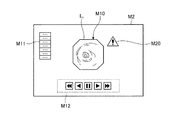
図5は、表示対象の画像Imを含む画面の表示例を示す模式図である。図5に示す画面M1は、画像Imが表示される画像表示領域M10の他、被検体5である患者の氏名及び年齢等の患者に関する情報や検査に関する情報が表示される情報表示欄M11と、再生操作ボタン群M12とを含む。 FIG. 5 is a schematic diagram illustrating a display example of a screen including the image Im to be displayed. Screen M1 shown in FIG. 5, another image display area M10 which an image I m is displayed, the information display field M11 information about information and testing for patients, such as patient's name and age is the subject 5 is displayed And a reproduction operation button group M12.
再生操作ボタン群M12は、画像表示領域M10における画像の再生動作を制御する指示をユーザが入力する際に用いる操作ボタンの集合であり、例えば、頭出しボタン、コマ送りボタン、一時停止ボタン、早送りボタン、再生ボタン、逆再生ボタン、巻き戻しボタン、停止ボタン等を含む。再生操作ボタン群M12に対する入力部11を用いた所定のポインタ操作(例えば、いずれかの操作ボタンに対するクリック操作)が行われると、該ポインタ操作に応じた操作信号が表示制御部161に入力される。
The reproduction operation button group M12 is a set of operation buttons used when a user inputs an instruction to control an image reproduction operation in the image display area M10. For example, a search button, a frame advance button, a pause button, and a fast forward button are used. Button, playback button, reverse playback button, rewind button, stop button, etc. When a predetermined pointer operation using the
一方、判定対象の範囲に特定画像が含まれる場合(ステップS16:Yes)、表示データ生成部163は、特定画像が存在する旨の情報を表す表示データを生成する(ステップS18)。この際、実施の形態1においては、表示データとして、所定の形状を有するアイコンを表すデータを作成する。
On the other hand, when the specific image is included in the determination target range (step S16: Yes), the display
この場合、続くステップS17において、表示制御部161は、画像Ij(図3においては画像Im)を含む画面を作成すると共に、ステップS18において生成された表示データに基づき、特定画像が存在する旨の情報を、判定対象の範囲に含まれる特定画像(図3においては画像In)の特性に応じた態様で該画面に配置し、表示部15に表示させる。ここで、判定対象の範囲に含まれる特定画像の特性には、表示対象の画像Ijから該特定画像までの画像の枚数又は表示時間の他、特定画像の特徴量や類似度、特定画像から検出された特徴部の種類、該特定画像の撮像時におけるカプセル型内視鏡2の速度変化等が含まれる。
In this case, in the subsequent step S17, the
図6は、画像Imを含む画面に対して特定画像が存在する旨の情報が配置された画面の表示例を示す模式図である。図6に示す画面M2は、図5に示す画面M1に対し、特定画像が存在する旨の情報としてのアイコンM20をさらに含む。画面M2内におけるアイコンM20の位置は、画像表示領域M10の周辺領域であれば特に限定されないが、ユーザが画像表示領域M10から視線をずらすことなくアイコンM20の表示/非表示や表示態様の変化を認識できるように、画像観察の妨げにならない範囲で、できるだけ画像表示領域M10の近傍にアイコンM20を配置すると良い。 Figure 6 is a schematic diagram showing a display example of a screen information indicating that the specific image exists for a screen including the image I m is arranged. Screen M2 shown in FIG. 6 further includes an icon M20 as information indicating that a specific image exists, compared to screen M1 shown in FIG. The position of the icon M20 in the screen M2 is not particularly limited as long as it is a peripheral area of the image display area M10. However, the user can change the display / non-display of the icon M20 and the display mode without shifting the line of sight from the image display area M10. The icon M20 may be arranged as close as possible to the image display area M10 within a range that does not hinder image observation so that the image can be recognized.
また、表示制御部161は、併せて、特定画像の特性の1つとして、特定画像が表示されるまでの画像の枚数や時間等の情報を、アイコンM20内又は画面M1の所定の位置にテキスト表示しても良い。
In addition, the
続くステップS19において、表示制御部161は、画像Ijに続いて表示すべき次の画像があるか否かを、パラメータjの値に基づいて判定する。具体的には、画像の表示順序が時系列である場合にはj=Nに至ったか否かが判定され、時系列の逆順である場合にはj=1に至ったか否かが判定される。
In subsequent step S19, the
次の画像があると判定された場合(ステップS19:Yes)、制御部16はパラメータjを次に表示する画像の画像番号に更新する(ステップS20)。その後、画像処理装置1の動作はステップS15に戻る。一方、次の画像がないと判定された場合(ステップS19:No)、画像処理装置1の動作は終了する。
When it is determined that there is a next image (step S19: Yes), the
以上説明したように、実施の形態1によれば、表示対象の画像から表示順序が所定枚数後又は表示時刻が所定時間後の画像までの範囲に特定画像が含まれる場合に、特定画像が存在する旨の情報を画面に表示するので、ユーザは、過剰な負担を感じることなく、画像から得られる情報の突然の変化に対して備えることができる。また、特定画像が表示されるまでの枚数や時間等を併せて表示する場合、ユーザは、特定画像が表示されるタイミングを具体的に予測することができるので、さらに効率の良い観察を行なうことが可能となる。 As described above, according to the first embodiment, the specific image exists when the specific image is included in the range from the display target image to the image after the predetermined number of display orders or the display time is after the predetermined time. Since the information to the effect is displayed on the screen, the user can be prepared for a sudden change in the information obtained from the image without feeling an excessive burden. In addition, when displaying the number of images and time until the specific image is displayed together, the user can specifically predict the timing at which the specific image is displayed, so that more efficient observation is performed. Is possible.
実施の形態1において、表示制御部161は、画面M2に表示されるアイコンM20の表示態様を、判定対象の範囲に含まれる特定画像の特性に応じて変化させても良い。以下、特定画像の特性に応じてアイコンM20の表示態様を変化させた変形例を説明する。
In the first embodiment, the
(変形例1−1)
上記実施の形態1においては、特定画像が表示されるまでの画像の枚数や時間をアイコンM20内にテキスト表示することとしたが、これらの枚数や時間に応じてアイコンM20を変化させても良い。
(Modification 1-1)
In the first embodiment, the number of images and the time until the specific image is displayed are displayed as text in the icon M20. However, the icon M20 may be changed according to the number of images and the time. .
一例として、アイコンM20の色調を変化させる場合、初めにアイコンM20を例えば薄い赤で表示し、上記枚数又は時間が減少するにつれて、アイコンM20を徐々に濃い赤に変化させる。 As an example, when changing the color tone of the icon M20, the icon M20 is first displayed in, for example, light red, and the icon M20 is gradually changed to dark red as the number or time decreases.
別の例として、アイコンM20の明度を変化させる場合、初めにアイコンM20の明度を低くして表示し、上記枚数又は時間が減少するにつれて、アイコンM20の明度を徐々に高くする。 As another example, when changing the brightness of the icon M20, the brightness of the icon M20 is first displayed with a low brightness, and as the number or time decreases, the brightness of the icon M20 is gradually increased.
さらに別の例として、アイコンM20を点滅表示しても良い。この場合、初めにアイコンM20の点滅周期を長くして表示し、上記枚数又は時間が減少するにつれて、アイコンM20の点滅周期を徐々に短くする。 As yet another example, the icon M20 may be displayed blinking. In this case, the icon M20 is first displayed with a longer blinking cycle, and as the number or time decreases, the blinking cycle of the icon M20 is gradually shortened.
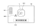
さらに別の例として、アイコンM20のサイズを変化させる場合、初めにアイコンM20のサイズを小さくして表示し(図6参照)、上記枚数又は時間が減少するにつれて、アイコンM20のサイズを徐々に大きくする(図7参照)。 As yet another example, when the size of the icon M20 is changed, the icon M20 is first reduced in size (see FIG. 6), and the size of the icon M20 is gradually increased as the number or time decreases. (See FIG. 7).
さらに別の例として、アイコンM20の表示位置を変化させる場合、初めにアイコンM20を画像表示領域M10から若干離れた位置に表示し、上記枚数又は時間が減少するにつれて、アイコンM20の位置を画像表示領域M10に徐々に近づける。 As another example, when the display position of the icon M20 is changed, the icon M20 is first displayed at a position slightly away from the image display area M10, and the position of the icon M20 is displayed as an image as the number or time decreases. Gradually approach the region M10.
さらに、上述したアイコンM20の表示態様を互いに組み合わせても良い。例えば、初めにアイコンM20のサイズを小さく、且つ画像表示領域M10から若干離れた位置に表示し、上記枚数又は時間が減少するにつれて、アイコンM20のサイズを徐々に大きくすると共に画像表示領域M10に徐々に近づける。 Furthermore, the display modes of the icon M20 described above may be combined with each other. For example, the icon M20 is first reduced in size and displayed at a position slightly away from the image display area M10. As the number or time decreases, the icon M20 is gradually increased in size and gradually displayed in the image display area M10. Move closer to.
(変形例1−2)
アイコンM20の表示態様を、特定画像の類似度に応じて変化させても良い。ここで、特定画像としては、隣接する画像との類似度が所定値よりも低い画像、即ち、隣接する画像からの変化が大きい画像も抽出され得る。そこで、特定画像として抽出された画像の類似度に応じてアイコンM20の表示態様を変化させる。
(Modification 1-2)
You may change the display mode of icon M20 according to the similarity degree of a specific image. Here, as the specific image, an image whose similarity with an adjacent image is lower than a predetermined value, that is, an image having a large change from the adjacent image can be extracted. Therefore, the display mode of the icon M20 is changed according to the similarity of the image extracted as the specific image.
一例として、アイコンM20の色調を変化させる場合、類似度が高いほど(隣接する画像との変化が小さいほど)アイコンM20を例えば薄い赤で表示し、類似度が低いほど(隣接する画像との変化が大きいほど)アイコンM20を例えば濃い赤で表示する。 As an example, when the color tone of the icon M20 is changed, the icon M20 is displayed in, for example, light red as the similarity is higher (the change from the adjacent image is smaller), and as the similarity is lower (change from the adjacent image). For example, the icon M20 is displayed in dark red.
別の例として、アイコンM20の明度を変化させる場合、類似度が高いほど(隣接する画像との変化が小さいほど)アイコンM20の明度を低くし、類似度が低いほど(隣接する画像との変化が大きいほど)アイコンM20の明度を高くする。 As another example, when changing the brightness of the icon M20, the higher the similarity (the smaller the change from the adjacent image), the lower the brightness of the icon M20, and the lower the similarity (the change from the adjacent image). The brightness of the icon M20 is increased.
さらに別の例として、アイコンM20を点滅させる場合、類似度が高いほどアイコンM20の点滅周期を長くし、類似度が低いほどアイコンM20の点滅周期を短くする。 As another example, when the icon M20 is blinked, the blinking cycle of the icon M20 is lengthened as the similarity is high, and the blinking cycle of the icon M20 is shortened as the similarity is low.
さらに別の例として、アイコンM20のサイズを変化させる場合、類似度が高いほどアイコンM20のサイズを小さくし、類似度が低いほどアイコンM20のサイズを大きくする。 As another example, when the size of the icon M20 is changed, the size of the icon M20 is decreased as the similarity is higher, and the size of the icon M20 is increased as the similarity is lower.
さらに別の例として、アイコンM20の表示位置を変化させる場合、類似度が高いほどアイコンM20を画像表示領域M10から離し、類似度が低いほどアイコンM20を画像表示領域M10に近づける。
さらに、上述したアイコンM20の表示態様を互いに組み合わせても良い。
As another example, when the display position of the icon M20 is changed, the icon M20 is moved away from the image display area M10 as the similarity is higher, and the icon M20 is moved closer to the image display area M10 as the similarity is lower.
Furthermore, the display modes of the icon M20 described above may be combined with each other.
(変形例1−3)
アイコンM20の表示態様を、特定画像において検出された病変等の種類に応じて変化させても良い。
一例として、アイコンM20の色調を変化させる場合、例えば、潰瘍が検出された特定画像に対してはアイコンM20を緑色で表示し、出血が検出された特定画像に対してはアイコンM20を赤色で表示し、腫瘍が検出された特定画像に対してはアイコンM20を黄色で表示するといった表示態様が挙げられる。
(Modification 1-3)
The display mode of the icon M20 may be changed according to the type of lesion detected in the specific image.
As an example, when changing the color tone of the icon M20, for example, the icon M20 is displayed in green for a specific image in which an ulcer is detected, and the icon M20 is displayed in red for a specific image in which bleeding is detected. And the display aspect of displaying the icon M20 in yellow with respect to the specific image from which the tumor was detected is mentioned.
(変形例1−4)
アイコンM20の表示態様を、特定画像において検出された病変等の程度に応じて変化させても良い。病変等の程度としては、例えば、潰瘍や出血の領域の面積、腫瘍の大きさ等が判定される。
(Modification 1-4)
The display mode of the icon M20 may be changed according to the degree of the lesion detected in the specific image. As the degree of the lesion, for example, the area of the ulcer or bleeding region, the size of the tumor, and the like are determined.
一例として、アイコンM20の色調を変化させる場合、例えば、潰瘍や出血の面積や腫瘍の大きさが小さい特定画像に対してはアイコンM20を薄い赤色で表示し、潰瘍や出血の面積や腫瘍の大きさが大きい特定画像に対してはアイコンM20を濃い赤色で表示する。 As an example, when the color tone of the icon M20 is changed, for example, the icon M20 is displayed in a light red color for a specific image having a small area of ulcer or bleeding or the size of the tumor, and The icon M20 is displayed in dark red for a specific image having a large size.
或いは、出血している潰瘍や出血の領域の面積、腫瘍の大きさ等に応じて、アイコンM20の明度や、アイコンM20を点滅させる際の点滅周期や、アイコンM20のサイズや、アイコンM20の表示位置を変化させても良い。 Alternatively, the brightness of the icon M20, the blinking cycle when the icon M20 is blinked, the size of the icon M20, and the display of the icon M20 according to the area of the bleeding ulcer, the area of the bleeding, the size of the tumor, etc. The position may be changed.
(変形例1−5)
アイコンM20の表示態様を、特定画像において検出された病変等の位置に応じて変化させても良い。例えば、特定画像を4分割した左下の領域から病変が検出された場合、図8に示すように、アイコンM20を画像表示領域M10の近傍の左下の領域に配置する。
(Modification 1-5)
The display mode of the icon M20 may be changed according to the position of a lesion or the like detected in the specific image. For example, when a lesion is detected from the lower left area obtained by dividing the specific image into four, as shown in FIG. 8, the icon M20 is arranged in the lower left area in the vicinity of the image display area M10.
以上説明したように、実施の形態1の変形例1−1〜1−5によれば、特定画像が存在する旨の情報を、判定対象の範囲に含まれる特定画像の特性に応じて表示するので、ユーザは、いつごろ特定画像が表示されるのか、或いは、どのような特定画像が表示されるのかといった情報を直感的に把握することが可能となる。従って、ユーザは、過剰な負担を感じることなく特定画像の表示に備えることができ、効率の良い観察を行なうことが可能となる。 As described above, according to the modified examples 1-1 to 1-5 of the first embodiment, information indicating that a specific image exists is displayed according to the characteristics of the specific image included in the determination target range. Therefore, the user can intuitively grasp information such as when the specific image is displayed or what specific image is displayed. Therefore, the user can prepare for the display of the specific image without feeling an excessive burden, and can perform efficient observation.
なお、ユーザは、画像表示領域M10を注視している場合、一般に、周辺視野の変化に関しては色調の変化よりも明度の変化に敏感である。従って、アイコンM20の色調を変化させる場合には、色調以外の表示要素(例えば、明度、点滅周期、サイズ)と組み合わせると良い。 When the user is gazing at the image display area M10, the change in the peripheral visual field is generally more sensitive to the change in brightness than the change in color tone. Therefore, when changing the color tone of the icon M20, it is preferable to combine with a display element other than the color tone (for example, brightness, blinking cycle, size).
(実施の形態2)
次に、本発明の実施の形態2について説明する。
図9は、本発明の実施の形態2に係る画像処理装置の構成を示すブロック図である。図9に示すように、本実施の形態2に係る画像処理装置6は、図2に示す制御部16の代わりに制御部61を備える。なお、制御部61以外の画像処理装置6の各部の構成及び動作は、実施の形態1と同様である。
(Embodiment 2)
Next, a second embodiment of the present invention will be described.
FIG. 9 is a block diagram showing a configuration of an image processing apparatus according to Embodiment 2 of the present invention. As shown in FIG. 9, the image processing apparatus 6 according to the second embodiment includes a control unit 61 instead of the
制御部61は、図2に示す制御部16に対し、スキップ部611をさらに有する。スキップ部611は、入力部11から表示部15の画面に表示された所定のアイコンを選択する信号が入力された場合に、該表示部15に表示させる画像の表示順序を特定画像にスキップさせる制御を行う。なお、スキップ部611以外の制御部61内の各部の動作は、実施の形態1と同様である。
The control unit 61 further includes a
図10は、画像処理装置6の動作を示すフローチャートである。なお、図10に示すステップS10〜S17の動作は、実施の形態1と同様である(図4参照)。
ステップS16において、判定対象の範囲に特定画像が含まれる場合(ステップS16:Yes)、表示データ生成部163は、特定画像が存在する旨の情報を表す表示データを生成する(ステップS21)。実施の形態2においては、該表示データとして、判定対象の範囲に含まれる特定画像の特性に応じて表示態様が変化させられるアイコンを表すデータと、表示対象の画像を特定画像にスキップさせる指示を入力する際に用いられる入力用のアイコンを表すデータとが生成される。
FIG. 10 is a flowchart showing the operation of the image processing apparatus 6. In addition, operation | movement of step S10-S17 shown in FIG. 10 is the same as that of Embodiment 1 (refer FIG. 4).
In step S16, when the specific image is included in the determination target range (step S16: Yes), the display
続くステップS22において、表示制御部161は、画像Ij(図3においてはIm)を含む画面を作成すると共に、ステップS21において生成された表示データに基づき、特定画像が存在する旨の情報を該画面に配置し、表示部15に表示させる。
In the subsequent step S22, the
図11は、画像Imを含む画面に対して特定画像が存在する旨の情報が配置された画面の表示例を示す模式図である。図11に示す画面M3は、図5に示す画面M1に対し、アイコンM20及び入力用のアイコンとしてのスキップボタンM30をさらに含む。このうち、アイコンM20の表示態様は、実施の形態1において説明したとおりである(図6参照)。 Figure 11 is a schematic diagram showing a display example of a screen information indicating that the specific image exists for a screen including the image I m is arranged. Screen M3 shown in FIG. 11 further includes an icon M20 and a skip button M30 as an input icon with respect to screen M1 shown in FIG. Among these, the display mode of the icon M20 is as described in the first embodiment (see FIG. 6).
一方、スキップボタンM30は、特定画像が存在する旨の情報が表示された当該特定画像をすぐに表示させる際にユーザが用いるアイコンである。スキップボタンM30に対する入力部11を用いた所定のポインタ操作(例えばクリック操作)が行われると、表示対象の画像をスキップさせる指示信号が制御部61に入力される。
On the other hand, the skip button M30 is an icon used by the user when the specific image on which information indicating that the specific image exists is displayed immediately. When a predetermined pointer operation (for example, a click operation) is performed on the skip button M30 using the
表示対象の画像をスキップさせる指示信号が入力された場合(ステップS23:Yes)、スキップ部611は、表示対象の画像の画像番号を当該特定画像の画像番号(図3の場合、j=n)にスキップさせる(ステップS24)。その後、画像処理装置6の動作はステップS15に戻る。
When the instruction signal for skipping the display target image is input (step S23: Yes), the
図12は、スキップボタンM30に対してポインタ操作がなされた後に、表示部15に表示される画面を示す模式図である。図12に示すように、画面M4の画像表示領域M10には、先に表示されていた画像Imに続いて、特定画像として抽出された画像Inが表示される。
FIG. 12 is a schematic diagram showing a screen displayed on the
一方、表示対象の画像をスキップさせる信号が入力されない場合(ステップS23:No)、画像処理装置6の動作は、ステップS19に移行する。ステップS19及びS20の動作は、実施の形態1と同様である。 On the other hand, when the signal for skipping the image to be displayed is not input (step S23: No), the operation of the image processing device 6 proceeds to step S19. The operations in steps S19 and S20 are the same as those in the first embodiment.
以上説明したように、実施の形態2によれば、表示順序が所定枚数後まで又は表示時刻が所定時間後までの範囲に特定画像が含まれる場合に、画像の表示順序をスキップして当該特定画像をすぐに表示させることができる。従って、ユーザは、特定画像が気になる場合に、すぐに特定画像を表示させて確認することができるので、効率の良い観察を行うことが可能となる。 As described above, according to the second embodiment, when the specific image is included in the range until the display order is after the predetermined number of images or the display time is after the predetermined time, the specific display is skipped. Images can be displayed immediately. Therefore, when the user is concerned about the specific image, the user can immediately display and confirm the specific image, so that efficient observation can be performed.
(実施の形態3)
次に、本発明の実施の形態3について説明する。
本実施の形態3においては、上記実施の形態1においては、特定画像が存在する旨の情報をアイコンによって表示したが、特定画像が存在する旨の情報の表示態様はアイコンに限定されない。例えば、画像の周囲に表示枠を設けることによって、特定画像が存在する旨を表しても良い。以下、実施の形態3における特定画像が存在する旨の情報の表示態様について説明する。なお、実施の形態3に係る画像処理装置の構成及び動作は、全体として実施の形態1と同様である(図2及び図4参照)。
(Embodiment 3)
Next, a third embodiment of the present invention will be described.
In the third embodiment, in the first embodiment, the information indicating that the specific image exists is displayed by the icon, but the display mode of the information indicating that the specific image exists is not limited to the icon. For example, a display frame may be provided around the image to indicate that the specific image exists. Hereinafter, a display mode of information indicating that a specific image exists in Embodiment 3 will be described. Note that the configuration and operation of the image processing apparatus according to the third embodiment are the same as those of the first embodiment as a whole (see FIGS. 2 and 4).
実施の形態3においては、表示対象の画像に対し、表示順序が所定枚数後まで又は表示時刻が所定時間後までの範囲に特定画像が含まれる場合、表示データ生成部163は、特定画像が存在する旨の情報を表す表示データとして、画像表示領域M10(図5参照)を囲む表示枠を表す表示データを作成する(図4のステップS18参照)。
In the third embodiment, when the specific image is included in the range until the display order is after the predetermined number of images or the display time is after the predetermined time with respect to the display target image, the display
この場合、表示制御部161は、表示対象の画像を含む画面に対し、さらに、ステップS18において生成された表示枠を表す表示データに基づいて、特定画像が存在する旨の情報を、判定対象の範囲に含まれる特定画像の特性に応じた態様で表示する(図4のステップS17参照)。
In this case, the
図13は、表示対象の画像を含む画面に対して特定画像が存在する旨の情報が配置された画面の表示例を示す模式図である。図13に示す画面M5は、図5に示す画面M1に対し、特定画像が存在する旨の情報としての表示枠M50をさらに含む。表示対象の画像Imに対し、表示順序が所定枚数後まで又は表示時刻が所定時間後までの範囲に特定画像が含まれる場合に、このような表示枠M50を表示することにより、ユーザは、過剰な負担を感じることなく、画像から得られる情報の突然の変化に対して備えることができる。 FIG. 13 is a schematic diagram illustrating a display example of a screen on which information indicating that a specific image exists is arranged on a screen including an image to be displayed. Screen M5 shown in FIG. 13 further includes a display frame M50 as information indicating that a specific image exists, compared to screen M1 shown in FIG. The image I m of the display target, when the display order or display time until after the predetermined number of sheets contain specific image range up after a predetermined time, by displaying such display frame M50, user, It is possible to prepare for a sudden change in information obtained from an image without feeling an excessive burden.
上記実施の形態3においては、特定画像が存在する場合にのみ表示枠M50を設けることとしたが、特定画像が存在しない場合にも表示枠M50を設けても良い。この場合、特定画像が存在する場合と存在しない場合とで、表示枠M50の色を変化させることにより、特定画像が存在する旨をユーザに認知させることとしても良い。 In the third embodiment, the display frame M50 is provided only when the specific image exists. However, the display frame M50 may be provided even when the specific image does not exist. In this case, the user may be made aware that the specific image exists by changing the color of the display frame M50 depending on whether the specific image exists or not.
また、実施の形態3において特定画像が存在する旨の情報として表示される表示枠M50の表示態様は、判定対象の範囲に含まれる特定画像の特性に応じて変化させても良い。以下、特定画像の特性に応じて表示枠M50の表示態様を変化させた変形例を説明する。 Further, the display mode of the display frame M50 displayed as information indicating that the specific image exists in the third embodiment may be changed according to the characteristics of the specific image included in the determination target range. Hereinafter, a modification in which the display mode of the display frame M50 is changed according to the characteristics of the specific image will be described.
(変形例3−1)
表示枠M50の表示態様を、特定画像が表示されるまでの画像の枚数や時間に応じて変化させても良い。
一例として、表示枠M50の色調を変化させる場合、上記枚数が多いとき又は時間が長いときには、表示枠M50を例えば薄い赤で表示し、上記枚数又は時間が減少するについれて、表示枠M50を徐々に濃い赤に変化させる。
(Modification 3-1)
The display mode of the display frame M50 may be changed according to the number of images and the time until the specific image is displayed.
As an example, when the color tone of the display frame M50 is changed, when the number of sheets is large or the time is long, the display frame M50 is displayed in, for example, light red, and the display frame M50 is displayed as the number of sheets or time decreases. Gradually change to dark red.
別の例として、表示枠M50の明度を変化させる場合、上記枚数が多いとき又は上記時間が長いときには、表示枠M50の明度を低くし、上記枚数又は時間が減少するにつれて、表示枠M50の明度を徐々に高くする。 As another example, when changing the brightness of the display frame M50, when the number of sheets is large or when the time is long, the brightness of the display frame M50 is lowered and the brightness of the display frame M50 is decreased as the number of sheets or time decreases. Increase gradually.
さらに別の例として、表示枠M50を点滅表示させる場合、上記枚数が多いとき又は上記時間が長いときには、表示枠M50の点滅周期を長くし、上記枚数又は時間が減少するにつれて、表示枠M50の点滅周期を徐々に短くする。 As another example, when the display frame M50 is displayed in a blinking manner, when the number of sheets is large or the time is long, the blinking cycle of the display frame M50 is lengthened, and as the number or time of the display frame M50 decreases, Gradually shorten the blinking cycle.
さらに別の例として、表示枠M50の幅を変化させる場合、上記枚数が多いとき又は上記時間が長いときには、表示枠M50の幅を狭くし、上記枚数又は時間が減少するにつれて、図7に示すように表示枠M50の幅を徐々に太くする。
さらに、上述した表示枠M50の表示態様を互いに組み合わせても良い。
As another example, when the width of the display frame M50 is changed, when the number of sheets is large or the time is long, the width of the display frame M50 is narrowed, and as the number of sheets or time decreases, as shown in FIG. In this way, the width of the display frame M50 is gradually increased.
Furthermore, the display modes of the display frame M50 described above may be combined with each other.
(変形例3−2)
表示枠M50の表示態様を、特定画像の類似度に応じて変化させても良い。
一例として、表示枠M50の色調を変化させる場合、類似度が高いほど(隣接する画像との変化が小さいほど)表示枠M50を例えば薄い赤で表示し、類似度が低いほど(隣接する画像との変化が大きいほど)表示枠M50を例えば濃い赤で表示する。
(Modification 3-2)
The display mode of the display frame M50 may be changed according to the similarity of the specific image.
As an example, when the color tone of the display frame M50 is changed, the higher the similarity is (the smaller the change from the adjacent image is), for example, the display frame M50 is displayed in light red, and the lower the similarity is (the adjacent image is The display frame M50 is displayed in, for example, dark red.
別の例として、表示枠M50の明度を変化させる場合、類似度が高いほど表示枠M50の明度を低くし、類似度が低いほど表示枠M50の明度を高くする。 As another example, when the brightness of the display frame M50 is changed, the brightness of the display frame M50 is decreased as the similarity is higher, and the brightness of the display frame M50 is increased as the similarity is lower.
さらに別の例として、表示枠M50を点滅させる場合、類似度が高いほど表示枠M50の点滅周期を長くし、類似度が低いほど表示枠M50の点滅周期を短くする。 As yet another example, when blinking the display frame M50, the higher the similarity is, the longer the blinking cycle of the display frame M50 is, and the lower the similarity is, the shorter the blinking cycle of the display frame M50 is.
さらに別の例として、表示枠M50の幅を変化させる場合、類似度が高いほど表示枠M50の幅を狭くし、類似度が低いほど表示枠M50の幅を太くする。
さらに、上述した表示枠M50の表示態様を互いに組み合わせても良い。
As another example, when the width of the display frame M50 is changed, the width of the display frame M50 is narrowed as the similarity is high, and the width of the display frame M50 is widened as the similarity is low.
Furthermore, the display modes of the display frame M50 described above may be combined with each other.
(変形例3−3)
表示枠M50の表示態様を、特定画像において検出された病変等の種類に応じて変化させても良い。
一例として、表示枠M50の色調を変化させる場合、例えば、潰瘍が検出された特定画像に対しては表示枠M50を緑色で表示し、出血が検出された特定画像に対しては表示枠M50を赤色で表示し、腫瘍が検出された特定画像に対しては表示枠M50を黄色で表示するといった表示態様が挙げられる。
(Modification 3-3)
The display mode of the display frame M50 may be changed according to the type of lesion detected in the specific image.
As an example, when changing the color tone of the display frame M50, for example, the display frame M50 is displayed in green for a specific image in which an ulcer is detected, and the display frame M50 is displayed for a specific image in which bleeding is detected. A display mode in which the display frame M50 is displayed in yellow for a specific image that is displayed in red and in which a tumor is detected can be mentioned.
(変形例3−4)
表示枠M50の表示態様を、特定画像において検出された病変等の程度に応じて変化させても良い。病変等の程度としては、例えば、潰瘍や出血の領域の面積、腫瘍の大きさ等が判定される。
(Modification 3-4)
The display mode of the display frame M50 may be changed according to the degree of the lesion detected in the specific image. As the degree of the lesion, for example, the area of the ulcer or bleeding region, the size of the tumor, and the like are determined.
一例として、表示枠M50の色調を変化させる場合、例えば、潰瘍や出血の面積や腫瘍の大きさが小さい特定画像に対しては表示枠M50を薄い赤色で表示し、潰瘍や出血の面積や腫瘍の大きさが大きい特定画像に対しては表示枠M50を濃い赤色で表示する。 As an example, when the color tone of the display frame M50 is changed, for example, the display frame M50 is displayed in a light red color for a specific image with a small area of ulcer or bleeding or tumor size, and the area or tumor of the ulcer or bleeding is displayed. For a specific image having a large size, the display frame M50 is displayed in dark red.
或いは、出血している潰瘍や出血の領域の面積、腫瘍の大きさ等に応じて、表示枠M50の明度や、表示枠M50を点滅させる際の点滅周期や、表示枠M50のサイズや、表示枠M50の表示位置を変化させても良い。 Alternatively, the brightness of the display frame M50, the blinking cycle when the display frame M50 is blinked, the size of the display frame M50, the display, etc., according to the area of the bleeding ulcer, bleeding area, tumor size, etc. The display position of the frame M50 may be changed.
(変形例3−5)
特定画像が存在する旨の情報としての表示枠の表示態様を、特定画像において検出された病変等の位置に応じて変化させても良い。図14及び図15は、変形例3−5における表示枠の表示態様の例を示す模式図である。
(Modification 3-5)
The display mode of the display frame as information indicating that the specific image exists may be changed according to the position of a lesion or the like detected in the specific image. 14 and 15 are schematic diagrams illustrating examples of display modes of display frames in Modification 3-5.
この場合、画像特定部143は、特定画像における病変等の存在領域を特定し、該存在領域を表すフラグを当該特定画像の画像データに付加する。表示制御部161は、画像データに付加された存在領域を表すフラグをもとに、画面上における表示枠を表示させる位置を決定する。なお、病変等の存在領域は、画像の上半分の領域、右上1/4の領域というように、大まかに規定して良い。
In this case, the
例えば、特定画像を4分割した右上の領域から病変が検出された場合、図14に示す画面M6のように、部分的な表示枠M51を画像表示領域M10の周囲の右上1/4の領域に配置する。また、特定画像の上半分の領域から病変が検出された場合、図15に示す画面M7のように、部分的な表示枠M52を画像表示領域M10の周囲の上半分の領域に配置する。
For example, when a lesion is detected from the upper right area obtained by dividing the specific image into four parts, the partial display frame M51 is changed to the
(変形例3−6)
図16は、変形例3−6における特定画像が存在する旨の情報の表示態様の例を示す模式図である。図16に示す画面M8のように、特定画像が存在する旨の情報として、表示枠M50に加えて、実施の形態2において説明したスキップボタンM30を併せて表示しても良い。
(Modification 3-6)
FIG. 16 is a schematic diagram illustrating an example of a display mode of information indicating that a specific image exists in Modification 3-6. As in the screen M8 shown in FIG. 16, the skip button M30 described in the second embodiment may be displayed together with the display frame M50 as information indicating that the specific image exists.
以上説明したように、実施の形態3の変形例3−1〜3−6によれば、特定画像が存在する旨の情報を、判定対象の範囲に含まれる特定画像の特性に応じて表示するので、ユーザは、いつごろ特定画像が表示されるのか、或いは、どのような特定画像が表示されるのかといった情報を直感的に把握することが可能となる。従って、ユーザは、過剰な負担を感じることなく特定画像の表示に備えることができ、効率の良い観察を行なうことが可能となる。 As described above, according to the modified examples 3-1 to 3-6 of the third embodiment, the information indicating that the specific image exists is displayed according to the characteristics of the specific image included in the determination target range. Therefore, the user can intuitively grasp information such as when the specific image is displayed or what specific image is displayed. Therefore, the user can prepare for the display of the specific image without feeling an excessive burden, and can perform efficient observation.
なお、上記実施の形態3及びその変形例3−1〜3−6においては、表示枠M50、M51、M52を画像表示領域M10の外周に接触させて表示したが、画像表示領域M10と表示枠50、51、52との間に隙間を設けても良い。この場合であっても、ユーザが、画像表示領域M10を注視しながら表示枠M50、51、52の表示/非表示や表示態様の変化を認識できるように、画像の観察の妨げにならない範囲で、できるだけ画像表示領域M10の近傍に表示枠50、51、52を配置すると良い。 In the third embodiment and its modifications 3-1 to 3-6, the display frames M50, M51, and M52 are displayed in contact with the outer periphery of the image display area M10. However, the image display area M10 and the display frame are displayed. You may provide a clearance gap between 50, 51, and 52. Even in this case, the user can recognize the display / non-display of the display frames M50, 51, and 52 and the change in the display mode while gazing at the image display area M10, so long as the user does not interfere with the image observation. The display frames 50, 51, and 52 are preferably arranged as close to the image display area M10 as possible.
また、上述したように、ユーザは、画像表示領域M10を注視している場合、一般に、周辺視野の変化に関しては色調の変化よりも明度の変化に敏感であるので、表示枠M50の色調を変化させる場合には、色調以外の表示要素(例えば、明度、点滅周期、サイズ)と組み合わせると良い。 Further, as described above, when the user is gazing at the image display region M10, the change in the peripheral visual field is generally more sensitive to the change in brightness than the change in color, so the user changes the color tone of the display frame M50. In this case, it is preferable to combine with display elements other than the color tone (for example, brightness, blinking cycle, size).
(実施の形態4)
次に本発明の実施の形態4について説明する。
本実施の形態4においては、特定画像が存在する旨の情報として、アイコンの代わりに特定画像そのものを表示する。なお、実施の形態4に係る画像処理装置の構成及び動作は、全体として実施の形態1と同様である。
(Embodiment 4)
Next, a fourth embodiment of the present invention will be described.
In the fourth embodiment, the specific image itself is displayed instead of the icon as information indicating that the specific image exists. The configuration and operation of the image processing apparatus according to the fourth embodiment are the same as those of the first embodiment as a whole.
実施の形態4においては、表示対象の画像に対する判定対象の範囲に特定画像が含まれる場合、表示データ生成部163は、特定画像が存在する旨の情報を表す表示データとして、当該特定画像の画像データを記憶部13から取得する(図4のステップS18参照)。
In the fourth embodiment, when the specific image is included in the determination target range with respect to the display target image, the display
この場合、表示制御部161は、表示対象の画像を含む画面に対し、さらに、ステップS18において取得された画像データに基づいて、判定対象の範囲に含まれる特定画像そのものを、当該特定画像の特性に応じた態様で表示する(図4のステップS17参照)。
In this case, the
図17は、表示対象の画像を含む画面に対して特定画像が存在する旨の情報が配置された画面の表示例を示す模式図である。図17に示す画面M9は、図5に示す画面M1に対し、特定画像が存在する旨の情報としての特定画像表示領域M90を含む。該特定画像表示領域M90には、ステップS16において特定画像である旨を示すフラグが付加されていると判定された画像Inが配置される。 FIG. 17 is a schematic diagram illustrating a display example of a screen on which information indicating that a specific image exists is arranged on a screen including an image to be displayed. A screen M9 shown in FIG. 17 includes a specific image display area M90 as information indicating that a specific image exists, compared to the screen M1 shown in FIG. The Specific image display area M90, the image I n, which is determined that the flag indicating that a specific image is added in step S16 is disposed.
特定画像表示領域M90の位置は、特定画像が表示されるまでの画像の枚数や時間に応じて変化させても良い。例えば、該枚数や時間が減少するにつれて、図18に示すように、特定画像表示領域M90を徐々に拡大すると共に、徐々に画像表示領域M10に近づけることにより、特定画像(画像In)が遠方から近づいてくるように表示しても良い。これにより、ユーザは、特定画像が表示されるタイミングを直感的に把握できるようになる。 The position of the specific image display area M90 may be changed according to the number of images and the time until the specific image is displayed. For example, as該枚number or time decreases, as shown in FIG. 18, gradually while enlarging the specific image display area M90, by approximating the image display area M10 gradually, specific image (image I n) is far You may display so that it may approach from. Thereby, the user can intuitively grasp the timing at which the specific image is displayed.
(変形例4)
次に、上記実施の形態1〜4の変形例4について説明する。
上記実施の形態1〜4においては、表示対象の画像Im(図3参照)から表示順序がd枚後又は表示時刻がTd時間後の画像までの範囲(判定対象の範囲)に、特定画像が1枚(画像In)のみ含まれる場合を説明した。しかしながら、判定対象の範囲に複数の特定画像が含まれる場合もある。このような場合、判定部162は、複数の特定画像を1つの特定画像群として処理しても良い。
(Modification 4)
Next, a fourth modification of the first to fourth embodiments will be described.
In the first to fourth embodiments, the display target image I m (see FIG. 3) is specified in a range (determination target range) from the display order after d images or the display time after T d time. The case where only one image (image I n ) is included has been described. However, a plurality of specific images may be included in the determination target range. In such a case, the
例えば、図19に示すように、判定対象の範囲から連続する複数の特定画像(画像In1〜In4)が検出された場合、表示対象の画像Imから特定画像として判定された最初の画像In1までの画像の枚数又は時間に応じて、特定画像が存在する旨の表示(アイコンM20、表示枠M50等)を行う。 For example, as shown in FIG. 19, when a plurality of specific image which is continuous from the scope of the determination target (image I n1 ~I n4) is detected, the first image determined as the specific image from the image I m to be displayed Depending on the number of images up to In 1 or the time, an indication that a specific image exists (icon M20, display frame M50, etc.) is performed.
以上説明したように、実施の形態1〜4の変形例4によれば、ユーザは、複数の表示データを一括して確認することが可能となる。従って、ユーザは、特定画像が存在する旨の情報を容易に把握することができるので、効率の良い観察を行うことが可能となる。 As described above, according to the fourth modification of the first to fourth embodiments, the user can check a plurality of display data at once. Therefore, the user can easily grasp the information that the specific image exists, and thus can perform efficient observation.
さらには、上記実施の形態1〜4、及び各実施の形態の変形例同士を適宜組み合わせても良い。 Furthermore, you may combine suitably the said Embodiment 1-4 and the modification of each embodiment.
例えば、特定画像から検出された病変の種類や程度に応じて特定画像が存在する旨の情報の表示態様を変化させる場合、特定画像として判定された最初の画像In1において検出された病変の種類や程度に基づいてアイコンM20や表示枠M50等の表示態様を変化させても良いし、画像In1〜In4において検出された病変の種類や程度の平均に基づいてこれらの表示態様を変化させても良い。 For example, when changing the display mode of the information indicating that the specific image exists according to the type and degree of the lesion detected from the specific image, the type of lesion detected in the first image In 1 determined as the specific image it may be changed the display mode such as icons M20 and display frame M50 based on the degree and, changing these display modes on the basis of the average of the detected lesion type and extent of the image I n1 ~I n4 May be.
また、判定対象の範囲から連続する複数の特定画像からなる画像群が複数検出された場合、特定画像が存在する旨の表示として、最初の画像群に対応する1つアイコンのみを表示しても良いし、複数の画像群にそれぞれ対応する複数のアイコンを表示しても良い。 In addition, when a plurality of image groups including a plurality of specific images that are consecutive from the determination target range are detected, only one icon corresponding to the first image group may be displayed as an indication that the specific image exists. Alternatively, a plurality of icons corresponding to a plurality of image groups may be displayed.
(実施の形態5)
次に、本発明の実施の形態5について説明する。
図20は、本発明の実施の形態5に係る画像処理装置の構成を示すブロック図である。図20に示すように、本実施の形態5に係る画像処理装置7は、図2に示す制御部16の代わりに制御部71を備えると共に、さらに通知部72を備える。なお、制御部71及び通知部72以外の画像処理装置7の各部の構成及び動作は、実施の形態1と同様である。
(Embodiment 5)
Next, a fifth embodiment of the present invention will be described.
FIG. 20 is a block diagram showing a configuration of an image processing apparatus according to Embodiment 5 of the present invention. As shown in FIG. 20, the image processing apparatus 7 according to the fifth embodiment includes a control unit 71 instead of the
制御部71は、図2に示す制御部16に対し、通知制御部711をさらに有する。通知制御部711は、判定部162により判定対象の範囲に特定画像が含まれると判定された場合に、特定画像が存在する旨を、例えば音声や通知音等の聴覚により知覚可能な手段によってユーザに通知する制御を行う。
通知部72は、例えば音声や通知音等を発生する音発生手段である。
The control unit 71 further includes a notification control unit 711 with respect to the
The notification unit 72 is a sound generating unit that generates, for example, a voice or a notification sound.
特定画像が存在する旨の通知は、具体例として次のような態様で行われる。
(1)特定画像が存在する場合、通知音を発生する。
(2)特定画像が存在する場合に通知音を発生し、特定画像が表示されるまでの画像の枚数が少なくなるにつれて、又は特定画像が表示されるまでの時間が短くなるにつれて、通知音の音量を徐々に大きくする、或いは、音程を徐々に高くする。或いは、通知音を間欠的に発生することとし、発生周期を徐々に短くしても良い。
(3)特定画像が存在する場合に通知音を発生し、特定画像の隣接する画像との類似度に応じて、通知音の音量又は音程又は発生周期を変化させる。
(4)特定画像が存在する場合に通知音を発生し、特定画像において検出された病変等の種類に応じて通知音の種類を変化させる。
(5)特定画像が存在する場合に通知音を発生し、特定画像において検出された病変等の程度に応じて通知音の音量又は音程を変化させる。
(6)特定画像が存在する場合に、特定画像が存在する旨のメッセージ及び特定画像が表示されるまでの画像の枚数又は時間を音声で読み上げる。
(7)特定画像が存在する場合に、特定画像が存在する旨のメッセージ及び特定画像の特性(類似度や検出された病変の種類や程度)を音声で読み上げる。
The notification that the specific image exists is performed in the following manner as a specific example.
(1) When a specific image exists, a notification sound is generated.
(2) A notification sound is generated when a specific image exists, and the notification sound is generated as the number of images until the specific image is displayed decreases or as the time until the specific image is displayed decreases. Increase the volume gradually or gradually increase the pitch. Alternatively, the notification sound may be generated intermittently and the generation cycle may be gradually shortened.
(3) A notification sound is generated when a specific image exists, and the volume, pitch, or generation cycle of the notification sound is changed according to the similarity between the specific image and an adjacent image.
(4) A notification sound is generated when a specific image exists, and the type of notification sound is changed according to the type of lesion detected in the specific image.
(5) A notification sound is generated when a specific image exists, and the volume or pitch of the notification sound is changed according to the degree of a lesion detected in the specific image.
(6) When a specific image exists, a message indicating that the specific image exists and the number of images or time until the specific image is displayed are read out by voice.
(7) When a specific image exists, a message to the effect that the specific image exists and characteristics of the specific image (similarity and detected lesion type and degree) are read out by voice.
さらには、これらの態様(1)〜(7)同士を適宜組み合わせても良い。また、これらの態様(1)〜(7)を実施の形態1〜4において説明した視覚(画面表示)による通知と組み合わせても良い。 Furthermore, these modes (1) to (7) may be appropriately combined. Further, these modes (1) to (7) may be combined with the visual (screen display) notification described in the first to fourth embodiments.
実施の形態5によれば、ユーザは、画面に表示された画像を注視しつつ、音声や通知音により、特定画像が存在する旨を把握することが可能となる。 According to the fifth embodiment, the user can grasp that the specific image exists by voice or notification sound while gazing at the image displayed on the screen.
(変形例5)
次に、本発明の実施の形態5の変形例5について説明する。
図20に示す通知制御部711及び通知部72は、判定部162により判定対象の範囲に特定画像が含まれると判定された場合に、特定画像が存在する旨を、触覚により知覚可能な手段によってユーザに通知しても良い。触覚により知覚可能な手段とは、例えば、振動や温度変化等が挙げられる。この場合、通知部72は、例えば振動を発生するバイブレータや、温度を変化させるヒータ等によって構成される。
(Modification 5)
Next, Modification 5 of Embodiment 5 of the present invention will be described.
When the
特定画像が存在する旨の通知は、具体例として次のような態様で行われる。
(1)特定画像が存在する場合に、画像処理装置7の入力部11として用いられるマウス等のデバイスや、ユーザが座る椅子等の部材を振動させる。
(2)特定画像が存在する場合に上記マウスや椅子等の部材を振動させ、特定画像が表示されるまでの画像の枚数や時間に応じて、振動量(強さ)や周期を変化させる。
(3)特定画像が存在する場合に、上記マウスや椅子等の部材の温度を変化させる。
(4)特定画像が存在する場合に、上記マウスや椅子等の部材の形状等を変化させる。具体的には、特定画像が存在する場合にマウスから突起状の部材を突出させる、或いは、椅子の座面や背もたれの傾きや硬さを変化させるといった態様が挙げられる。
The notification that the specific image exists is performed in the following manner as a specific example.
(1) When a specific image exists, a device such as a mouse used as the
(2) When a specific image exists, the members such as the mouse and the chair are vibrated, and the vibration amount (strength) and the period are changed according to the number of images and time until the specific image is displayed.
(3) When the specific image exists, the temperature of the member such as the mouse or the chair is changed.
(4) When a specific image exists, the shape of the member such as the mouse or the chair is changed. Specifically, when a specific image exists, there is a mode in which a protruding member is protruded from the mouse, or the inclination or hardness of the seating surface or backrest of the chair is changed.
さらには、これらの態様(1)〜(5)同士を適宜組み合わせても良い。また、これらの態様(1)〜(5)を実施の形態1〜4において説明した視覚(画面表示)による通知や、実施の形態5において説明した聴覚による通知と組み合わせても良い。 Furthermore, you may combine these aspects (1)-(5) suitably. These modes (1) to (5) may be combined with the visual (screen display) notification described in the first to fourth embodiments or the auditory notification described in the fifth embodiment.
以上説明した本発明は、実施の形態1〜5及びこれらの変形例に限定されるものではなく、仕様等に応じて種々変形することが可能であり、例えば上記実施の形態1〜5及びこれらの変形例に示される全構成要素からいくつかの構成要素を除外して形成しても良い。本発明の範囲内において、他の様々な実施の形態が可能であることは、上記記載から自明である。
The present invention described above is not limited to
1、6、7 画像処理装置
2 カプセル型内視鏡
3 受信装置
3a クレードル
4 受信アンテナユニット
4a〜4h 受信アンテナ
5 被検体
11 入力部
12 画像データ取得部
13 記憶部
14 演算部
15 表示部
16、61、71 制御部
72 通知部
141 画像処理部
142 位置算出部
143 画像特定部
161 表示制御部
162 判定部
163 表示データ生成部
611 スキップ部
711 通知制御部
DESCRIPTION OF
Claims (5)
前記画像群から、所定の特徴を有する特定画像を特定し、さらに、前記特定画像における前記所定の特徴が存在する領域を特定する画像特定部と、
前記画像群に含まれる画像を前記記憶部から時系列順又は時系列の逆順に取得し、取得した順に前記画像を表示部の画面に表示させる表示制御部と、
前記表示制御部が前記表示部に表示させる表示対象の画像から、該表示対象の画像に対して表示順序が所定枚数後又は表示時刻が所定時間後の画像までの範囲に、前記画像特定部により特定された前記特定画像が含まれるか否かを判定する判定部と、
前記範囲に前記特定画像が含まれると判定された場合に、前記特定画像が存在する旨の情報を表す表示データを生成する表示データ生成部と、
を備え、
前記表示制御部は、前記範囲に含まれる前記特定画像における前記所定の特徴が存在する領域に応じた前記画面の位置に前記表示データを配置することを特徴とする画像処理装置。 A storage unit for storing the image group;
From the images, and to identify the specific image having a predetermined feature, further image specifying unit for specifying a region in which the predetermined characteristic of the specific image exists,
A display control unit when acquired in reverse sequence order or chronological, and displays the image on the obtained sequence on the screen of Table radical 113 an image included in the image group from the storage unit,
By the image specifying unit, a range from a display target image displayed on the display unit by the display control unit to an image after a predetermined number of displays or a display time after a predetermined time with respect to the display target image. a determination section for determining whether or not include the specific image specified,
A display data generation unit that generates display data representing information indicating that the specific image exists when it is determined that the specific image is included in the range;
With
The image processing apparatus, wherein the display control unit arranges the display data at a position of the screen corresponding to a region where the predetermined feature exists in the specific image included in the range.
外部からの操作を入力する入力部と、
前記画面において前記入力用のアイコンを選択する操作が前記入力部から入力された場合に、前記表示部に表示させる画像を前記特定画像にスキップさせるスキップ部と、
をさらに備えることを特徴とする請求項1に記載の画像処理装置。 The display data is an input icon arranged on the screen,
An input unit for inputting an external operation;
A skip unit that causes an image to be displayed on the display unit to be skipped to the specific image when an operation for selecting the icon for input on the screen is input from the input unit;
The image processing apparatus according to claim 1 , further comprising:
前記特定画像は、画像内の所定の特徴量が所定の範囲内である画像、所定の特徴部が検出された画像、隣接する画像との類似度が所定値以下である画像、特定の位置若しくは領域が写った画像、又は、当該画像が撮像された際の前記カプセル型内視鏡の動きの変化が所定値以上である画像であることを特徴とする請求項1に記載の画像処理装置。 The image group includes images acquired by sequentially imaging the inside of the subject by a capsule endoscope introduced into the subject,
The specific image is an image in which a predetermined feature amount in the image is within a predetermined range, an image in which a predetermined feature is detected, an image in which the similarity with an adjacent image is a predetermined value or less, a specific position, The image processing apparatus according to claim 1 , wherein the image processing apparatus is an image in which an area is captured, or an image in which a change in movement of the capsule endoscope when the image is captured is a predetermined value or more.
Priority Applications (1)
| Application Number | Priority Date | Filing Date | Title |
|---|---|---|---|
| JP2013258657A JP6120762B2 (en) | 2013-12-13 | 2013-12-13 | Image processing device |
Applications Claiming Priority (1)
| Application Number | Priority Date | Filing Date | Title |
|---|---|---|---|
| JP2013258657A JP6120762B2 (en) | 2013-12-13 | 2013-12-13 | Image processing device |
Publications (3)
| Publication Number | Publication Date |
|---|---|
| JP2015112429A JP2015112429A (en) | 2015-06-22 |
| JP2015112429A5 JP2015112429A5 (en) | 2015-12-03 |
| JP6120762B2 true JP6120762B2 (en) | 2017-04-26 |
Family
ID=53526791
Family Applications (1)
| Application Number | Title | Priority Date | Filing Date |
|---|---|---|---|
| JP2013258657A Active JP6120762B2 (en) | 2013-12-13 | 2013-12-13 | Image processing device |
Country Status (1)
| Country | Link |
|---|---|
| JP (1) | JP6120762B2 (en) |
Cited By (1)
| Publication number | Priority date | Publication date | Assignee | Title |
|---|---|---|---|---|
| US11627864B2 (en) | 2018-09-26 | 2023-04-18 | Fujifilm Corporation | Medical image processing apparatus, endoscope system, and method for emphasizing region of interest |
Families Citing this family (17)
| Publication number | Priority date | Publication date | Assignee | Title |
|---|---|---|---|---|
| EP3360461A4 (en) * | 2015-11-10 | 2019-05-08 | Olympus Corporation | Endoscope device |
| JP6581923B2 (en) | 2016-03-03 | 2019-09-25 | 富士フイルム株式会社 | Image processing apparatus, operating method thereof and operating program |
| WO2018069992A1 (en) | 2016-10-12 | 2018-04-19 | オリンパス株式会社 | Insertion system |
| WO2018159347A1 (en) * | 2017-02-28 | 2018-09-07 | 富士フイルム株式会社 | Processor device, endoscope system, and method of operating processor device |
| EP3603483A4 (en) * | 2017-03-30 | 2020-04-22 | FUJIFILM Corporation | Endoscope system and method for operating same |
| WO2019146077A1 (en) * | 2018-01-26 | 2019-08-01 | オリンパス株式会社 | Endoscope image processing device, endoscope image processing method, and endoscope image processing program |
| JP7000206B2 (en) * | 2018-03-06 | 2022-01-19 | 富士フイルム株式会社 | Medical image processing equipment, medical image processing methods, and medical image processing programs |
| JP2022010368A (en) * | 2018-04-13 | 2022-01-14 | 学校法人昭和大学 | Large intestine endoscope observation support device, large intestine endoscope observation support method, and program |
| JP2019180966A (en) * | 2018-04-13 | 2019-10-24 | 学校法人昭和大学 | Endoscope observation support apparatus, endoscope observation support method, and program |
| JP7264407B2 (en) * | 2018-04-13 | 2023-04-25 | 学校法人昭和大学 | Colonoscopy observation support device for training, operation method, and program |
| EP3841957A4 (en) * | 2018-08-20 | 2021-10-13 | FUJIFILM Corporation | Medical image processing system |
| WO2020054604A1 (en) | 2018-09-11 | 2020-03-19 | 日本電気株式会社 | Information processing device, control method, and program |
| WO2020071086A1 (en) | 2018-10-04 | 2020-04-09 | 日本電気株式会社 | Information processing device, control method, and program |
| JPWO2021029293A1 (en) * | 2019-08-13 | 2021-02-18 | ||
| JP7290729B2 (en) * | 2019-08-13 | 2023-06-13 | 富士フイルム株式会社 | Image diagnosis support device, endoscope system, operating method of image diagnosis support device, and image diagnosis support program |
| JPWO2021132023A1 (en) * | 2019-12-26 | 2021-07-01 | ||
| CN115397304A (en) * | 2020-04-08 | 2022-11-25 | 富士胶片株式会社 | Medical image processing system, processor device for recognition processing, and method for operating medical image processing system |
Family Cites Families (7)
| Publication number | Priority date | Publication date | Assignee | Title |
|---|---|---|---|---|
| JP4416393B2 (en) * | 2002-12-04 | 2010-02-17 | 株式会社日立メディコ | Medical image display device |
| JP4751593B2 (en) * | 2004-11-02 | 2011-08-17 | オリンパス株式会社 | Image display device, image display method, and image display program |
| JP4916114B2 (en) * | 2005-01-04 | 2012-04-11 | オリンパス株式会社 | Endoscope device |
| JP2009050321A (en) * | 2007-08-23 | 2009-03-12 | Olympus Corp | Image processor |
| JP2009131319A (en) * | 2007-11-28 | 2009-06-18 | Olympus Corp | Image processing apparatus and image processing system |
| JP5220780B2 (en) * | 2010-02-05 | 2013-06-26 | オリンパス株式会社 | Image processing apparatus, endoscope system, program, and operation method of image processing apparatus |
| JP5504028B2 (en) * | 2010-03-29 | 2014-05-28 | 富士フイルム株式会社 | Observation support system, method and program |
-
2013
- 2013-12-13 JP JP2013258657A patent/JP6120762B2/en active Active
Cited By (1)
| Publication number | Priority date | Publication date | Assignee | Title |
|---|---|---|---|---|
| US11627864B2 (en) | 2018-09-26 | 2023-04-18 | Fujifilm Corporation | Medical image processing apparatus, endoscope system, and method for emphasizing region of interest |
Also Published As
| Publication number | Publication date |
|---|---|
| JP2015112429A (en) | 2015-06-22 |
Similar Documents
| Publication | Publication Date | Title |
|---|---|---|
| JP6120762B2 (en) | Image processing device | |
| EP3080998B1 (en) | System and method for controlling the display of an image stream | |
| US20210015432A1 (en) | Surgery support system, information processing apparatus, and program | |
| US20200046451A1 (en) | Case display apparatus, case displaying method, and storage medium | |
| JP5676063B1 (en) | Medical device and method of operating medical device | |
| JP5774645B2 (en) | Method and apparatus for acquiring video on an MRI apparatus and providing information on a screen | |
| US9530205B2 (en) | Polyp detection apparatus and method of operating the same | |
| EP2721997A1 (en) | Method of obtaining image and providing information on screen of magnetic resonance imaging apparatus, and apparatus thereof | |
| KR20160139810A (en) | Method and apparatus for displaying a medical image | |
| CN102668556A (en) | Medical support apparatus, medical support method, and medical support system | |
| CN110741334B (en) | Display control device, display control method, and display control program | |
| KR102519424B1 (en) | Method of displaying a ultrasound image and apparatus thereof | |
| JP2006302043A (en) | Image-displaying device, image-displaying method, and image-displaying program | |
| JP5822545B2 (en) | Image processing apparatus, image processing apparatus control method, and program | |
| JP6004875B2 (en) | MEDICAL IMAGE DISPLAY DEVICE, MEDICAL IMAGE DISPLAY METHOD, AND PROGRAM | |
| CN105310653A (en) | Apparatus and method of providing non-visual information and computer-aided diagnosis system using the same | |
| JP2011110281A (en) | Electronic endoscope apparatus | |
| JP7091845B2 (en) | Medical diagnostic system | |
| JP5262649B2 (en) | Medical image display apparatus and program | |
| JP2019040333A (en) | Information processing device, information processing method, computer program and time series data for display control | |
| JP2014226515A (en) | Diagnosis support system | |
| JP6978975B2 (en) | Information output device and information output method | |
| JP2009000342A (en) | Medical image display | |
| JP7456702B1 (en) | Programs, information processing systems and information processing methods | |
| JP2015012434A (en) | Form confirmation support device, method and program and form confirmation support system |
Legal Events
| Date | Code | Title | Description |
|---|---|---|---|
| A711 | Notification of change in applicant |
Free format text: JAPANESE INTERMEDIATE CODE: A712 Effective date: 20150422 |
|
| RD02 | Notification of acceptance of power of attorney |
Free format text: JAPANESE INTERMEDIATE CODE: A7422 Effective date: 20150526 |
|
| A521 | Request for written amendment filed |
Free format text: JAPANESE INTERMEDIATE CODE: A523 Effective date: 20151020 |
|
| A621 | Written request for application examination |
Free format text: JAPANESE INTERMEDIATE CODE: A621 Effective date: 20151020 |
|
| A131 | Notification of reasons for refusal |
Free format text: JAPANESE INTERMEDIATE CODE: A131 Effective date: 20161101 |
|
| A521 | Request for written amendment filed |
Free format text: JAPANESE INTERMEDIATE CODE: A523 Effective date: 20161219 |
|
| TRDD | Decision of grant or rejection written | ||
| A01 | Written decision to grant a patent or to grant a registration (utility model) |
Free format text: JAPANESE INTERMEDIATE CODE: A01 Effective date: 20170314 |
|
| A61 | First payment of annual fees (during grant procedure) |
Free format text: JAPANESE INTERMEDIATE CODE: A61 Effective date: 20170328 |
|
| R151 | Written notification of patent or utility model registration |
Ref document number: 6120762 Country of ref document: JP Free format text: JAPANESE INTERMEDIATE CODE: R151 |
|
| R250 | Receipt of annual fees |
Free format text: JAPANESE INTERMEDIATE CODE: R250 |
|
| R250 | Receipt of annual fees |
Free format text: JAPANESE INTERMEDIATE CODE: R250 |
|
| R250 | Receipt of annual fees |
Free format text: JAPANESE INTERMEDIATE CODE: R250 |
|
| R250 | Receipt of annual fees |
Free format text: JAPANESE INTERMEDIATE CODE: R250 |