JP6118030B2 - Measuring apparatus, exposure apparatus, and device manufacturing method - Google Patents
Measuring apparatus, exposure apparatus, and device manufacturing method Download PDFInfo
- Publication number
- JP6118030B2 JP6118030B2 JP2012048613A JP2012048613A JP6118030B2 JP 6118030 B2 JP6118030 B2 JP 6118030B2 JP 2012048613 A JP2012048613 A JP 2012048613A JP 2012048613 A JP2012048613 A JP 2012048613A JP 6118030 B2 JP6118030 B2 JP 6118030B2
- Authority
- JP
- Japan
- Prior art keywords
- head
- diffraction grating
- alignment
- detected
- measuring
- Prior art date
- Legal status (The legal status is an assumption and is not a legal conclusion. Google has not performed a legal analysis and makes no representation as to the accuracy of the status listed.)
- Active
Links
Images


Classifications
-
- G—PHYSICS
- G03—PHOTOGRAPHY; CINEMATOGRAPHY; ANALOGOUS TECHNIQUES USING WAVES OTHER THAN OPTICAL WAVES; ELECTROGRAPHY; HOLOGRAPHY
- G03F—PHOTOMECHANICAL PRODUCTION OF TEXTURED OR PATTERNED SURFACES, e.g. FOR PRINTING, FOR PROCESSING OF SEMICONDUCTOR DEVICES; MATERIALS THEREFOR; ORIGINALS THEREFOR; APPARATUS SPECIALLY ADAPTED THEREFOR
- G03F9/00—Registration or positioning of originals, masks, frames, photographic sheets or textured or patterned surfaces, e.g. automatically
- G03F9/70—Registration or positioning of originals, masks, frames, photographic sheets or textured or patterned surfaces, e.g. automatically for microlithography
- G03F9/7003—Alignment type or strategy, e.g. leveling, global alignment
- G03F9/7007—Alignment other than original with workpiece
- G03F9/7015—Reference, i.e. alignment of original or workpiece with respect to a reference not on the original or workpiece
-
- G—PHYSICS
- G03—PHOTOGRAPHY; CINEMATOGRAPHY; ANALOGOUS TECHNIQUES USING WAVES OTHER THAN OPTICAL WAVES; ELECTROGRAPHY; HOLOGRAPHY
- G03F—PHOTOMECHANICAL PRODUCTION OF TEXTURED OR PATTERNED SURFACES, e.g. FOR PRINTING, FOR PROCESSING OF SEMICONDUCTOR DEVICES; MATERIALS THEREFOR; ORIGINALS THEREFOR; APPARATUS SPECIALLY ADAPTED THEREFOR
- G03F9/00—Registration or positioning of originals, masks, frames, photographic sheets or textured or patterned surfaces, e.g. automatically
- G03F9/70—Registration or positioning of originals, masks, frames, photographic sheets or textured or patterned surfaces, e.g. automatically for microlithography
- G03F9/7088—Alignment mark detection, e.g. TTR, TTL, off-axis detection, array detector, video detection
Description
本発明は、測定装置、露光装置及びデバイスの製造方法に関する。 The present invention relates to a measuring apparatus, an exposure apparatus, and a device manufacturing method.
フォトリソグラフィー技術を用いて半導体デバイスを製造する際に、レチクル(マスク)のパターンを、投影光学系を介して、ウエハ等の基板に投影してパターンを転写する露光装置が使用されている。露光装置では、基板を保持したステージを移動させて基板上のショット領域を変えながらパターンの転写を繰り返している。従って、レチクルのパターンを基板上のショット領域に正確に転写するためには、基板を保持するステージの位置決めを高精度に行う必要がある。ステージの位置決めに関する技術については、従来から幾つか提案されている(特許文献1乃至3参照)。 2. Description of the Related Art When manufacturing a semiconductor device using photolithography technology, an exposure apparatus is used that projects a pattern of a reticle (mask) onto a substrate such as a wafer via a projection optical system and transfers the pattern. In the exposure apparatus, pattern transfer is repeated while moving the stage holding the substrate to change the shot area on the substrate. Therefore, in order to accurately transfer the reticle pattern to the shot area on the substrate, it is necessary to position the stage holding the substrate with high accuracy. Several techniques related to stage positioning have been proposed (see Patent Documents 1 to 3).
特許文献1には、回折格子の干渉原理を用いてステージの位置を測定する技術が提案されている。特許文献2には、光学式変位センサなどを用いてステージの2軸方向の変位を同時に測定する技術が提案されている。特許文献3には、回折格子の干渉原理及び干渉計を並列に用いてステージの位置を測定する技術が提案されている。
Patent Document 1 proposes a technique for measuring the position of the stage using the interference principle of a diffraction grating.
しかしながら、従来技術では、回折格子の指標を描画する際の描画誤差や回折格子を取り付けする際の取り付け誤差などに起因して、ステージの位置を測定する際に測定誤差が発生する問題がある。また、回折格子の温度分布変化や経時変化に伴う回折格子の歪みに起因して、ステージの位置を測定する際に測定誤差が発生する問題もある。 However, the conventional technique has a problem that a measurement error occurs when measuring the position of the stage due to a drawing error when drawing the index of the diffraction grating or an attachment error when attaching the diffraction grating. In addition, there is a problem that a measurement error occurs when measuring the position of the stage due to a diffraction grating distortion caused by a temperature distribution change of the diffraction grating or a change with time.
そこで、本発明は、このような従来技術の課題に鑑みてなされ、物体の位置の測定に有利な技術を提供することを例示的目的とする。 Therefore, the present invention has been made in view of the problems of the prior art, and an object of the present invention is to provide a technique advantageous for measuring the position of an object.
上記目的を達成するために、本発明の一側面としての測定装置は、第1物体に対する第2物体の相対的な位置を測定する測定装置であって、前記第1物体に設けられた回折格子と、前記第2物体に設けられた第1ヘッド及び第2ヘッドとを含み、前記第1ヘッド又は前記第2ヘッドで前記第1物体に対する前記第2物体の相対的な位置を測定する測定部と、前記第2物体に設けられた複数のアライメントマークを検出することで前記第2物体の位置を測定するアライメントスコープと、前記測定部で測定した前記相対的な位置を補正する処理を行う処理部と、を有し、前記複数のアライメントマークが設けられた領域における前記第1ヘッド及び前記第2ヘッドの配列方向の長さは、前記第1ヘッドと前記第2ヘッドとの間の距離以上であり、前記処理部は、前記アライメントスコープが前記複数のアライメントマークのそれぞれを検出するように前記第2物体を位置決めして前記第1ヘッド及び前記第2ヘッドのそれぞれで前記回折格子上の位置を検出する検出処理と、前記検出処理において前記第1ヘッド又は前記第2ヘッドで検出された前記回折格子上の位置を基準位置として、前記第1ヘッド及び前記第2ヘッドのうち一方のヘッドで以前に検出された前記回折格子上の位置を他方のヘッドの視野の中心に位置決めした状態で前記一方のヘッドで以前に検出された前記回折格子上の位置とは別の位置を前記一方のヘッドで検出する処理を前記一方のヘッドが前記回折格子の全面を検出するまで繰り返して前記回折格子の変形量を求める第1処理と、前記回折格子の変形量に基づいて、前記測定部で測定した前記相対的な位置を補正する第2処理と、を行うことを特徴とする。 In order to achieve the above object, a measuring apparatus according to one aspect of the present invention is a measuring apparatus for measuring a relative position of a second object with respect to a first object, and a diffraction grating provided on the first object. And a first head and a second head provided on the second object, and the first head or the second head measures a relative position of the second object with respect to the first object. An alignment scope for measuring the position of the second object by detecting a plurality of alignment marks provided on the second object, and a process for correcting the relative position measured by the measurement unit A length in the arrangement direction of the first head and the second head in an area where the plurality of alignment marks are provided is equal to or greater than a distance between the first head and the second head And The processing unit positions the second object so that the alignment scope detects each of the plurality of alignment marks, and detects a position on the diffraction grating by each of the first head and the second head. Detection process and previously detected by one of the first head and the second head using the position on the diffraction grating detected by the first head or the second head in the detection process as a reference position A position different from the position on the diffraction grating previously detected by the one head is detected by the one head while the position on the diffraction grating is positioned at the center of the field of view of the other head. a first process of the process one of the head seek deformation amount of the diffraction grating repeatedly until it detects the entire surface of the diffraction grating, the amount of deformation of the diffraction grating Zui it, and performing a second processing of correcting the relative position measured by the measurement unit.
本発明の更なる目的又はその他の側面は、以下、添付図面を参照して説明される好ましい実施形態によって明らかにされるであろう。 Further objects and other aspects of the present invention will become apparent from the preferred embodiments described below with reference to the accompanying drawings.
本発明によれば、例えば、物体の位置の測定に有利な技術を提供することができる。 According to the present invention, it is possible to provide a technique that is advantageous for measuring the position of an object, for example.
以下、添付図面を参照して、本発明の好適な実施の形態について説明する。なお、各図において、同一の部材については同一の参照番号を付し、重複する説明は省略する。 DESCRIPTION OF EXEMPLARY EMBODIMENTS Hereinafter, preferred embodiments of the invention will be described with reference to the accompanying drawings. In addition, in each figure, the same reference number is attached | subjected about the same member and the overlapping description is abbreviate | omitted.
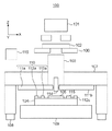
図1は、本発明の一側面としての露光装置100の構成を示す概略図である。露光装置100は、レチクル(マスク)102を照明光学系101で照明し、投影光学系103を介して、基板ステージ104に保持された基板105を露光する投影露光装置である。
FIG. 1 is a schematic diagram showing a configuration of an
投影光学系103は、レチクルステージ106に保持されたレチクル102のパターンを、ウエハや液晶基板などの基板105に投影する。装置基準を規定する基準フレーム107は、投影光学系103を支持する。マウント108は、基準フレーム107の制振機能及び床振動に対する除振機能を有する。基板ステージ104は、基板105を保持する。ステージ定盤109は、基板ステージ104を支持する。
The projection
測定部(第1測定部)110は、回折格子の干渉原理を用いて、第1物体としての基準フレーム107に対する第2物体としての基板ステージ104の相対的な位置を測定する。測定部110は、本実施形態では、回折格子111a〜111dと、第1ヘッド112a〜112d及び第2ヘッド113a〜113dとを含む。回折格子111a〜111dは、基準フレーム107(の下面)に設けられ(固定され)、第1ヘッド112a〜112d及び第2ヘッド113a〜113dは、基板ステージ104に設けられる(固定される)。但し、回折格子111a〜111dを基板ステージ104に設け、第1ヘッド112a〜112d及び第2ヘッド113a〜113dを基準フレーム107に設けてもよい。回折格子111a〜111dには、指標(目盛)が等間隔で高精度に形成されている。第1ヘッド112a〜112d及び第2ヘッド113a〜113dは、回折格子111a〜111dのそれぞれに対向して配置されている。
The measurement unit (first measurement unit) 110 measures the relative position of the
アライメントスコープ(第2測定部)114は、測定部110とは別体で構成され、基板ステージ104に固定されたアライメント用プレート115に形成されたアライメントマークを検出することで基板ステージ104の位置を測定する。なお、本実施形態では、アライメント用プレート115に形成されるアライメントマークは、互いに直交する2つの方向の座標(位置)を同時に検出することができるマークを想定している。但し、アライメント用プレート115に形成されるアライメントマークは、1つの方向の座標(位置)のみを検出することができるマークであってもよい。
The alignment scope (second measurement unit) 114 is configured separately from the
制御部116は、CPUやメモリなどを含み、露光装置100の全体(動作)を制御する。例えば、制御部116は、測定部110の測定結果やアライメントスコープ114の測定結果などを用いて基板ステージ104の駆動を制御し、基板ステージ104の位置決めを行う位置決め機構として機能する。また、基板ステージ104の位置決めにおいて、制御部116は、後述するように、基準フレーム107に対する基板ステージ104の相対的な位置を求める処理を行う処理部として機能する。
The
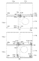
以下、露光装置100における基板ステージ104の位置決めに関連する処理について説明する。図2は、基板ステージ104と、回折格子111a〜111dと、第1ヘッド112a〜112dと、第2ヘッド113a〜113dと、アライメント用プレート115との位置関係の一例を示す図である。
Hereinafter, processing related to the positioning of the
図2に示すように、第1ヘッド112aと第2ヘッド113aとの間の間隔(距離)、第1ヘッド112cと第2ヘッド113cとの間の間隔は、X軸方向にd、Y軸方向にゼロである。また、第1ヘッド112bと第2ヘッド113bとの間の間隔、第1ヘッド112dと第2ヘッド113dとの間の間隔は、X軸方向にゼロ、Y軸方向にdである。アライメント用プレート115には、アライメントスコープ114で検出可能な複数のアライメントマーク(指標の検出基準位置)115a〜115iがX軸方向及びY軸方向に等間隔で形成されている。
As shown in FIG. 2, the distance (distance) between the
アライメント用プレート115において、左端に形成されたアライメントマーク115aと右端に形成されたアライメントマーク115cとの間の間隔(距離)は、本実施形態ではdであるが、d以上であればよい。同様に、アライメント用プレート115において、上端に形成されたアライメントマーク115aと下端に形成されたアライメントマーク115gとの間の間隔は、本実施形態ではdであるが、d以上であればよい。
In the
第1ヘッド112a〜112d、第2ヘッド113a〜113d及びアライメント用プレート115は、ゼロデュア(登録商標)やインバーなどの低熱膨張部材で基板ステージ104に一体的に固定されている。第1ヘッド112a〜112d、第2ヘッド113a〜113d及びアライメント用プレート115のそれぞれの間の間隔は常に保証され、回折格子111a〜111dの変形量を求める際の基準となる。ここで、回折格子111a〜111dの変形量とは、回折格子111a〜111dに描画された指標の描画誤差、基準フレーム107に対する回折格子111a〜111dの取り付け誤差、回折格子111a〜111dの歪みなどに起因する相対誤差量である。
The
回折格子111a〜111dの変形量を求める処理(第1処理)について説明する。本実施形態では、回折格子111a〜111dの仕様は、2次元型のインクリメンタル方式とする。但し、回折格子111a〜111dの仕様として、アブソリュート方式を採用してもよい。
A process (first process) for obtaining the deformation amounts of the
まず、回折格子111a〜111dの原点位置を第1ヘッド112a〜112d及び第2ヘッド113a〜113dで検出するために、図3に示すように、基板ステージ104を所定の位置に駆動する。所定の位置は、例えば、突き当てによって規定される。回折格子111a〜111dには、原点位置を識別可能な識別子OPa〜OPdが形成されている。基板ステージ104が所定の位置に位置している状態において、第1ヘッド112a〜112dのそれぞれで対応する識別子OPa〜OPdを検出することによって、回折格子111a〜111dの原点位置を検出する。
First, in order to detect the origin positions of the
次いで、アライメント用プレート115がアライメントスコープ114の測定位置MPに位置するように基板ステージ104を駆動する。例えば、図4(a)に示すように、アライメント用プレート115に形成された複数のアライメントマーク115a〜115iのうちアライメントマーク115aがアライメントスコープ114の測定位置MPに位置するように基板ステージ104を駆動する。そして、アライメントスコープ114でアライメントマーク115aを検出する。この際、アライメントスコープ114で検出されるアライメントマーク115aの位置(即ち、基板ステージ104の位置)を基準位置として、第1ヘッド112c及び第2ヘッド113cのそれぞれで回折格子111cの座標(回折格子上の位置)を検出する。上述したように、アライメント用プレート115には、複数のアライメントマーク115a〜115iが形成されている。同様に、図4(b)乃至図4(d)に示すように、アライメントマーク115b〜115iのそれぞれをアライメントスコープ114で順次検出しながら、第1ヘッド112c及び第2ヘッド113cのそれぞれで回折格子111cの座標を検出する。例えば、図4(b)は、アライメントマーク115dをアライメントスコープ114で検出しながら、第1ヘッド112c及び第2ヘッド113cのそれぞれで回折格子111cの座標を検出している状態を示している。図4(c)は、アライメントマーク115gをアライメントスコープ114で検出しながら、第1ヘッド112c及び第2ヘッド113cのそれぞれで回折格子111cの座標を検出している状態を示している。図4(d)は、アライメントマーク115iをアライメントスコープ114で検出しながら、第1ヘッド112c及び第2ヘッド113cのそれぞれで回折格子111cの座標を検出している状態を示している。また、図4(a)乃至図4(d)では、第1ヘッド112c及び第2ヘッド113cで検出された回折格子111cの座標を黒丸(ドット)で示している。
Next, the
なお、図4(a)乃至図4(d)では、アライメントマーク115a〜115iのそれぞれをアライメントスコープ114で順次検出しながら、第1ヘッド112c及び第2ヘッド113cのそれぞれで回折格子111cの座標を検出すると説明した。但し、実際には、図5(a)及び図5(b)に示すように、第1ヘッド112a、112b及び112d、及び、第2ヘッド113a、113b及び113dのそれぞれでも対応する回折格子111a、111b及び111dの座標を検出する。即ち、アライメントマーク115a〜115iのそれぞれをアライメントスコープ114で順次検出しながら、第1ヘッド112a〜112d及び第2ヘッド113a〜113dで対応する回折格子111a乃至111dの座標を検出する。図5(a)は、アライメントマーク115aをアライメントスコープ114で検出しながら、第1ヘッド112a〜112d及び第2ヘッド113a〜113dで対応する回折格子111a乃至111dの座標を検出している状態を示している。図5(b)は、アライメントマーク115iをアライメントスコープ114で検出しながら、第1ヘッド112a〜112d及び第2ヘッド113a〜113dで対応する回折格子111a乃至111dの座標を検出している状態を示している。また、図5(a)及び図5(b)では、第1ヘッド112a〜112d及び第2ヘッド113a〜113dで検出された回折格子111a〜111dの座標を黒丸(ドット)で示している。
In FIGS. 4A to 4D, the coordinates of the
次に、第1ヘッド112c及び第2ヘッド113cのうち一方のヘッドで検出された回折格子111cの座標を他方のヘッドで検出できるように基板ステージ104を駆動する。例えば、図6(a)に示すように、第2ヘッド113cで以前に検出された回折格子111cの座標を第1ヘッド112cの視野の中心に位置決めした状態で、第2ヘッド113cで回折格子111cの座標を検出する。この際、第2ヘッド113cで検出される座標は、第2ヘッド113cで以前に検出された回折格子111cの座標とは別の座標(位置)である。ここで、第1ヘッド112c及び第2ヘッド113cのみでは、図6(d)以降の回折格子111cの座標(Z方向)を検出することができない。但し、実際には、他の第1ヘッド112a、112b及び112d、他の第2ヘッド113a、113b及び113dも同時に回折格子の座標を検出している。例えば、第1ヘッド112b及び第2ヘッド113bで回折格子111bの座標を検出する際には、他の第1ヘッド及び第2ヘッドで回折格子111a、111c及び111dの座標も同時に検出している。これにより、図6(d)以降の回折格子111cの座標も検出することができる。
Next, the
このような処理を繰り返して、図6(b)乃至図6(e)に示すように、回折格子111cの全面(の座標)を検出する(即ち、回折格子111cの全面を検出するまで処理を繰り返す)。図6(b)乃至図6(e)では、第1ヘッド112c及び第2ヘッド113cで検出された回折格子111cの座標を黒丸(ドット)で示している。かかる検出結果から回折格子111cの変形量を求めることができる。なお、図6(a)乃至図6(e)では、回折格子111cの変形量を求めることについて説明した。但し、実際には、第1ヘッド112a、112b及び112d、及び、第2ヘッド113a、113b及び113dを用いて、回折格子111a、111b及び111dについても同様な処理を行う。これにより、回折格子111a、111b及び111dのそれぞれの変形量を求めることができる。
By repeating such processing, as shown in FIGS. 6B to 6E, the entire surface (coordinates) of the
基板ステージ104の位置決めの際には、まず、回折格子111a〜111dの変形量に基づいて、測定部110で測定された基準フレーム107に対する基板ステージ104の相対的な位置を補正する処理(第2処理)を行う。これにより、回折格子111a〜111dの変形に起因する測定部110の測定誤差を低減させることができ、基板ステージ104の位置決めを高精度に行うことが可能となる。
When positioning the
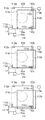
アライメント用プレート115は、図7(a)乃至図7(c)に示すように、基板ステージ104における位置や寸法を変更することが可能である。上述した処理で回折格子111a〜111dの変形量を求める場合には、実際には、アライメント用プレート115に形成されたアライメントマーク115a〜115iやアライメントスコープ114に起因する誤差が含まれてしまう。従って、アライメントスコープ114で検出されたアライメントマーク115a〜115iの位置を基準位置とする計測を繰り返すと、誤差が累積(増大)してしまう。このような誤差を低減させるためには、例えば、図7(a)に示すように、アライメント用プレート115を配置すればよい。図7(a)では、第1ヘッド112a〜112d及び第2ヘッド113a〜113dで回折格子上の座標(位置)を検出する際の初期検出位置が回折格子上のX座標の中央付近となるようにアライメント用プレート115を配置している。そして、X座標の正方向又は負方向の回折格子上の座標を検出する際には、X座標の中央付近における初期検出位置を基準にする。これにより、初期検出位置からのX座標の正方向又は負方向への計測の繰り返し回数を減少することが可能となり、累積される誤差を低減することができる。また、図7(b)に示すように、アライメント用プレート115の寸法を拡大させたり、図7(c)に示すように、複数のアライメント用プレート115を用いたりしても、累積される誤差を低減することができる。
As shown in FIGS. 7A to 7C, the
また、第1ヘッド112a〜112dと第2ヘッド113a〜113dとの間の距離が設計距離からずれている場合もある。このような場合には、上述した処理で求められる回折格子111a〜111dの変形量に、第1ヘッド112a〜112dと第2ヘッド113a〜113dとの間の距離の設計距離からのずれ量に起因する誤差が含まれてしまう。かかる誤差を低減する処理を図8(a)乃至図8(c)を参照して説明する。なお、ここでは、第1ヘッド112a〜112dと第2ヘッド113a〜113dとの間の距離が1軸方向(X軸方向)のみにずれている場合を例に説明する。
In addition, the distance between the
図8(a)に示すように、第1ヘッド112aと第2ヘッド113aとの間の距離はd、アライメント用プレート115に形成された隣接するアライメントマーク間の距離はd/N(Nは、任意の自然数)である。また、右端に形成されたアライメントマークと左端に形成されたアライメントマークとの間の距離は、L3(d以上)である。従って、アライメント用プレート115に形成されたアライメントマークは、第1ヘッド112aと第2ヘッド113aとの間の距離dと等しい距離で形成された第1アライメントマーク115mと第2アライメントマーク115nを含んでいる。
As shown in FIG. 8A, the distance between the
まず、図8(a)に示すように、アライメントスコープ114が第1アライメントマーク115mを検出するように基板ステージ104を位置決めして第2ヘッド113aで回折格子111aの座標(位置)を検出する(第3処理)。
First, as shown in FIG. 8A, the
次いで、図8(b)に示すように、第1アライメントマーク115mの左隣に形成されたアライメントマークをアライメントスコープ114で順次検出していく。そして、アライメントスコープ114が第2アライメントマーク115nを検出するように基板ステージ104を位置決めして第1ヘッド112aで回折格子111aの座標(位置)を検出する(第4処理)。なお、図8(b)では、実際には、水平方向のみに移動させる基板ステージ104の位置を、下方向にも移動させて図示している。
Next, as shown in FIG. 8B, the
次に、第1アライメントマーク115mの検出時に第2ヘッド113aで検出した回折格子111aの座標と第2アライメントマーク115nの検出時に第1ヘッド112aで検出した回折格子111aの座標との差分を求める。そして、かかる差分を第1ヘッド112aと第2ヘッド113aとの間の距離の設計距離からのずれ量とする(第5処理)。なお、第1ヘッド112b〜112dと第2ヘッド113b〜113dとの間の距離の設計距離からのずれ量も同様にして求めることができる。
Next, the difference between the coordinates of the
第1ヘッド112aと第2ヘッド113aとの間の距離は、理想的には、d(設計距離)であるが、実際には、設計距離からΔdずれている。通常、設計距離からのずれ量Δdは非常に小さい値であるため、回折格子111aが変形していたとしても、ずれ量Δdを検出する際の誤差量は極めて小さくなる。
The distance between the
基板ステージ104の位置決めの際には、まず、回折格子111a〜111dの変形量、及び、ずれ量Δdに基づいて、測定部110で測定された基準フレーム107に対する基板ステージ104の相対的な位置を補正する。これにより、回折格子111a〜111dの変形や設計距離からのずれ量に起因する測定部110の測定誤差を低減させることができ、基板ステージ104の位置決めを高精度に行うことが可能となる。
When positioning the
なお、図8(c)に示すように、回折格子上の異なる複数の座標(位置)の検出結果から2つのヘッド間の距離の設計距離からのずれ量を求めることで、回折格子の変形に起因する誤差が低減され、設計距離からのずれ量をより高精度に求めることができる。 As shown in FIG. 8C, the amount of deviation from the design distance of the distance between the two heads is obtained from the detection results of a plurality of different coordinates (positions) on the diffraction grating, thereby deforming the diffraction grating. The resulting error is reduced, and the amount of deviation from the design distance can be determined with higher accuracy.
また、アライメント用プレート115に形成されたアライメントマーク115a〜115iが理想位置からずれている場合もある。このような場合には、図9に示すように、干渉計118a及び118bを用いて、アライメントマーク115a〜115iの理想位置からのずれ量を検出すればよい。
Further, the
干渉計118a及び118bは、基準フレーム107に設けられ(固定され)、測定軸を通過して基板ステージ104に設けられた干渉計ミラー119a及び119bで反射され、測定軸を戻ってくる光を検出して基板ステージ104の位置を検出する。但し、上述したように、干渉計118a及び118bは、アライメントマーク115a〜115iの理想位置からのずれ量を検出する検出部としても機能する。温度、気温、湿度が一定に維持(管理)された空間においては、干渉計118a及び118bのそれぞれの精度は、測定軸の光路長L1及びL2に比例する。従って、干渉計118a及び118bは、光路長L1及びL2が短ければ短いほど、アライメントマーク115a〜115iの理想位置からのずれ量を高精度に検出することができる。
アライメントマーク115a〜115iの理想位置からのずれ量を検出する際には、まず、アライメントスコープ114でアライメントマークを検出できる位置に基板ステージ104を駆動する。かかる位置は、設計上のアライメントマークの位置(理想位置)に基づいて決定される。次いで、アライメントスコープ114でアライメント用プレート115に形成されたアライメントマーク115a〜115iのそれぞれを検出する。この際、アライメントマーク115a〜115iの理想位置からのずれ量を干渉計118a及び118bで検出する。そして、アライメントマーク115a〜115iの理想位置からのずれ量に基づいてアライメントスコープ114で検出したアライメントマーク115a〜115iの位置(即ち、基板ステージ104の位置)を補正した補正位置を基準位置とする。これにより、アライメント用プレート115に形成されたアライメントマーク間の相対位置が理想的な相対位置からずれている場合であっても、回折格子上の座標(位置)を高精度に検出することが可能となる。
When detecting the shift amount of the
また、これまでは、アライメント用プレート115に形成されたアライメントマーク115a〜115iの位置を基準位置とする場合について説明したが、干渉計118a及び118bで測定された基板ステージ104の位置を基準位置とすることも可能である。換言すれば、アライメント用プレート115を用いることなく、光路長L1及びL2が十分に短くなる範囲で測定された基板ステージ104の位置を基準位置とすることができる。
In the above description, the position of the
光路長L1及びL2が十分に短くなる位置に基板ステージ104が位置決めされている場合、干渉計118a及び118bの精度は、第1ヘッド112a〜112d及び第2ヘッド113a〜113dの精度と同等又はそれ以上となる。この場合、干渉計118a及び118bの測定範囲が第1ヘッド112a〜112dと第2ヘッド113a〜113dとの間の距離d以上であれば、上述した処理によって、回折格子111a〜111dの全面の座標(位置)を高精度に検出することができる。
When the
具体的には、まず、回折格子111a〜111dの原点位置を第1ヘッド112a〜112d及び第2ヘッド113a〜113dで検出する。次いで、干渉計118a及び118bで基板ステージ104の位置を測定しながら、予め決められた規定位置に基板ステージ104を駆動する。かかる規定位置は、光路長L1及びL2が十分に短くなる基板ステージ104の位置である。この状態において、干渉計118a及び118bで測定される基板ステージ104の位置を基準位置として、第1ヘッド112a〜112d及び第2ヘッド113a〜113dで対応する回折格子111a〜111dの座標(位置)を検出する。そして、干渉計118a及び118bで基板ステージ104の位置を測定しながら基板ステージ104を順次駆動して、第1ヘッド112a〜112d及び第2ヘッド113a〜113dで対応する回折格子111a〜111dの座標を検出する。図10(a)乃至図10(c)は、干渉計118a及び118bで基板ステージ104の位置を測定しながら、第1ヘッド112c及び第2ヘッド113cのそれぞれで回折格子111cの座標を検出している状態を示している。図10(a)乃至図10(c)では、第1ヘッド112c及び第2ヘッド113cで検出された回折格子111cの座標を黒丸(ドット)で示している。
Specifically, first, the origin positions of the
次に、第1ヘッド112c及び第2ヘッド113cのうち一方のヘッドで検出された回折格子111cの座標を他方のヘッドで検出できるように基板ステージ104を駆動する。例えば、図11(a)に示すように、第2ヘッド113cで以前に検出された回折格子111cの座標を第1ヘッド112cの視野の中心に位置決めした状態で、第2ヘッド113cで回折格子111cの座標を検出する。この際、第2ヘッド113cで検出される座標は、第2ヘッド113cで以前に検出された回折格子111cの座標とは別の座標(位置)である。図11(a)乃至図11(c)に示すように、このような処理を繰り返すことで、回折格子111cの全面(の座標)を検出する(即ち、回折格子111cの全面を検出するまで処理を繰り返す)。図11(a)乃至図11(c)では、第1ヘッド112c及び第2ヘッド113cで検出された回折格子111cの座標を黒丸(ドット)で示している。かかる検出結果から回折格子111cの変形量を求めることができる。なお、図10(a)乃至図10(c)、及び、図11(a)乃至図11(c)では、回折格子111cの変形量を求めることについて説明した。但し、実際には、第1ヘッド112a、112b及び112d、及び、第2ヘッド113a、113b及び113dを用いて、回折格子111a、111b及び111dについても同様な処理を行う。これにより、回折格子111a、111b及び111dのそれぞれの変形量を求めることができる。
Next, the
また、回折格子111a〜111dは、図12に示すように、切り欠き部120a〜120dを有していてもよい。切り欠き部120a〜120dを有する回折格子111a〜111dであっても、上述した処理によって、回折格子111a〜111dのそれぞれの変形量を求めることができる。
Moreover, the
また、露光装置100は、基板ステージ104と基板ステージ104に設けられた第1ヘッド及び第2ヘッドに対応する回折格子111a〜111dとのセットを複数有する場合もある。例えば、露光装置100が基板ステージ104と基板ステージ104に設けられた第1ヘッド及び第2ヘッドに対応する回折格子111a〜111dとのセットを2つ有する構成、所謂、ツインステージの構成を有する場合について考える。
The
ツインステージの構成では、一般的に、計測ステーションにてアライメント処理を行い、露光ステーションで露光処理を行うことが多く、2つの基板ステージは、各ステーション間をスワップ移動する。2つの基板ステージに設けられた第1ヘッドと、第2ヘッドと、アライメント用プレートとの位置関係、及び、2つの基板ステージに設けられたアライメント用プレートに形成されたアライメントマークの位置関係は、理想的には、同一である。但し、実際には、2つの基板ステージに設けられた第1ヘッドと、第2ヘッドと、アライメント用プレートとの位置関係、及び、2つの基板ステージに設けられたアライメント用プレートに形成されたアライメントマークの位置関係は異なっている。従って、上述した処理を計測ステーション及び露光ステーションのそれぞれで行うことが必要となる。例えば、計測ステーション及び露光ステーションのそれぞれに設けられた回折格子が図2に示すような構成を有する場合には、上述した処理を4回行う必要がある。従って、基板ステージの数がM、回折格子の検出領域の数がNである場合、上述した処理を行う回数はM×Nとなる。 In the twin stage configuration, in general, alignment processing is often performed at a measurement station, and exposure processing is often performed at an exposure station, and the two substrate stages are swapped between the stations. The positional relationship between the first head provided on the two substrate stages, the second head, and the alignment plate, and the positional relationship between the alignment marks formed on the alignment plates provided on the two substrate stages are: Ideally, they are the same. However, in practice, the positional relationship between the first head, the second head, and the alignment plate provided on the two substrate stages, and the alignment formed on the alignment plates provided on the two substrate stages. The positional relationship of the marks is different. Therefore, it is necessary to perform the above-described processing at each of the measurement station and the exposure station. For example, when the diffraction grating provided in each of the measurement station and the exposure station has a configuration as shown in FIG. 2, the above-described processing needs to be performed four times. Therefore, when the number of substrate stages is M and the number of detection areas of the diffraction grating is N, the number of times the above-described processing is performed is M × N.
なお、本実施形態では、アライメント用プレートに形成されたアライメントマーク及び回折格子の座標(位置)を検出する際の検出回数について特に説明しなかったが、必要精度に応じて任意に設定することができる。 In the present embodiment, the number of detections when detecting the coordinates (positions) of the alignment marks and diffraction gratings formed on the alignment plate is not particularly described, but may be arbitrarily set according to the required accuracy. it can.
また、上述した処理、即ち、回折格子の変形量を求めるタイミングは、一般的には、定期メンテナンスを行うタイミングと同じにすればよい。但し、露光装置の通常稼働中にも定期的に回折格子の変形量を求め、その変形量の変化が所定の基準値を超えた場合に、エラーを通知する、或いは、上述した処理を行うことも可能である。これにより、回折格子の温度分布変化や経時変化に伴う回折格子の歪み(変形)にも対応することが可能となり、基板ステージの位置決め精度を中長期的に安定させることができる。 In addition, the above-described processing, that is, the timing for obtaining the deformation amount of the diffraction grating may be generally the same as the timing for performing the regular maintenance. However, the amount of deformation of the diffraction grating is periodically obtained even during normal operation of the exposure apparatus, and when the change in the amount of deformation exceeds a predetermined reference value, an error is notified or the processing described above is performed. Is also possible. As a result, it is possible to cope with distortion (deformation) of the diffraction grating accompanying a change in temperature distribution of the diffraction grating and a change with time, and the positioning accuracy of the substrate stage can be stabilized in the medium to long term.
また、アライメント用プレートに形成されたアライメントマークの理想位置からのずれ量を求める方法としては、上述した干渉計118a及び118bを用いた方法の他に、例えば、以下の2つの方法がある。なお、上述した干渉計118a及び118bを用いた方法では、アライメントスコープ114を用いている。但し、レチクル102の位置(及びレチクル102と基板105との相対的な位置)を測定するアライメントスコープを用いてもアライメントマークの理想位置からのずれ量を求めることが可能である。
In addition to the method using the
第1の方法は、基準基板を用いる方法である。具体的には、まず、基板ステージ104に基準基板を配置する。次いで、第1ヘッド112a〜112d及び第2ヘッド113a〜113dで対応する回折格子111a〜111dの座標(位置)を検出しながら、アライメントスコープ114で基準基板上の基準マークを検出する。そして、基準基板上の基準マークの位置を基準として、アライメント用プレート115に形成されたアライメントマークの理想位置からのずれ量を求める。
The first method is a method using a reference substrate. Specifically, first, a reference substrate is placed on the
第2の方法は、検査用レチクル及び検査用基板を用いる方法である。まず、レチクルステージ106に検査用レチクルを載置し、基板ステージ104に検査用基板を載置する。次いで、アライメントスコープ114でアライメント用プレート115に形成されたアライメントマークを検出する。次に、アライメントマークの位置を基準として、第1ヘッド112a〜112d及び第2ヘッド113a〜113dで対応する回折格子111a〜111dの座標を検出しながら検査用基板を露光する。そして、検査用基板における露光結果を基準として、アライメント用プレート115に形成された形成されたアライメントマークの理想位置からのずれ量を求める。
The second method uses an inspection reticle and an inspection substrate. First, an inspection reticle is placed on the
また、投影光学系の光軸位置を測定するセンサが基板ステージに配置されている場合には、かかるセンサをアライメントスコープ114の代わりに用いてもよい。即ち、投影光学系の光軸中心位置を基準として、上述した処理を行うことも可能である。
Further, when a sensor for measuring the optical axis position of the projection optical system is disposed on the substrate stage, such a sensor may be used instead of the
このように、露光装置100は、回折格子111a〜111dの変形量に基づいて、第1ヘッド112a〜112d及び第2ヘッド113a〜113dで測定された基板ステージ104の位置を補正して基板ステージ104の位置決めを行う。従って、露光装置100は、基板ステージ104の位置決め精度を向上させて、高品位なデバイス(半導体素子、LCD素子、撮像素子(CCDなど)、薄膜磁気ヘッドなど)を提供することができる。かかるデバイスは、露光装置100を用いてフォトレジスト(感光剤)が塗布された基板(ウエハ、ガラスプレート等)を露光する工程と、露光された基板を現像する工程と、その他の周知の工程と、を経ることによって製造される。
As described above, the
以上、本発明の好ましい実施形態について説明したが、本発明はこれらの実施形態に限定されないことはいうまでもなく、その要旨の範囲内で種々の変形及び変更が可能である。 As mentioned above, although preferable embodiment of this invention was described, it cannot be overemphasized that this invention is not limited to these embodiment, A various deformation | transformation and change are possible within the range of the summary.
Claims (5)
前記第1物体に設けられた回折格子と、前記第2物体に設けられた第1ヘッド及び第2ヘッドとを含み、前記第1ヘッド又は前記第2ヘッドで前記第1物体に対する前記第2物体の相対的な位置を測定する測定部と、
前記第2物体に設けられた複数のアライメントマークを検出することで前記第2物体の位置を測定するアライメントスコープと、
前記測定部で測定した前記相対的な位置を補正する処理を行う処理部と、を有し、
前記複数のアライメントマークが設けられた領域における前記第1ヘッド及び前記第2ヘッドの配列方向の長さは、前記第1ヘッドと前記第2ヘッドとの間の距離以上であり、
前記処理部は、
前記アライメントスコープが前記複数のアライメントマークのそれぞれを検出するように前記第2物体を位置決めして前記第1ヘッド及び前記第2ヘッドのそれぞれで前記回折格子上の位置を検出する検出処理と、
前記検出処理において前記第1ヘッド又は前記第2ヘッドで検出された前記回折格子上の位置を基準位置として、前記第1ヘッド及び前記第2ヘッドのうち一方のヘッドで以前に検出された前記回折格子上の位置を他方のヘッドの視野の中心に位置決めした状態で前記一方のヘッドで以前に検出された前記回折格子上の位置とは別の位置を前記一方のヘッドで検出する処理を前記一方のヘッドが前記回折格子の全面を検出するまで繰り返して前記回折格子の変形量を求める第1処理と、
前記回折格子の変形量に基づいて、前記測定部で測定した前記相対的な位置を補正する第2処理と、
を行うことを特徴とする測定装置。 A measuring device for measuring a relative position of a second object with respect to a first object,
A diffraction grating provided on the first object; a first head and a second head provided on the second object; and the second object with respect to the first object by the first head or the second head. A measuring unit for measuring the relative position of
An alignment scope for measuring the position of the second object by detecting a plurality of alignment marks provided on the second object;
A processing unit that performs a process of correcting the relative position measured by the measurement unit,
The length in the arrangement direction of the first head and the second head in the region where the plurality of alignment marks is provided is equal to or greater than the distance between the first head and the second head,
The processor is
A detection process of positioning the second object so that the alignment scope detects each of the plurality of alignment marks and detecting a position on the diffraction grating by each of the first head and the second head;
The diffraction previously detected by one of the first head and the second head using the position on the diffraction grating detected by the first head or the second head in the detection process as a reference position. said one processing of detecting a different location in the one of the head and a position on the diffraction grating which is detected previously in the one head while positioning the position on the grid with the center of the visual field of the other head A first process of repeatedly calculating the deformation amount of the diffraction grating until the head of the first surface detects the entire surface of the diffraction grating;
A second process for correcting the relative position measured by the measurement unit based on the deformation amount of the diffraction grating;
A measuring device characterized in that
前記処理部は、前記検出部で検出された前記理想位置からのずれ量に基づいて前記アライメントスコープで測定された前記第2物体の位置を補正することを特徴とする請求項1に記載の測定装置。 A detection unit for detecting a shift amount of the alignment mark from an ideal position;
2. The measurement according to claim 1, wherein the processing unit corrects the position of the second object measured by the alignment scope based on a deviation amount from the ideal position detected by the detection unit. apparatus.
前記処理部は、
前記アライメントスコープが前記第1アライメントマークを検出するように前記第2物体を位置決めして前記第2ヘッドで前記回折格子上の位置を検出する第3処理と、
前記アライメントスコープが前記第2アライメントマークを検出するように前記第2物体を位置決めして前記第1ヘッドで前記回折格子上の位置を検出する第4処理と、
前記第3処理で検出された前記回折格子上の位置と前記第4処理で検出された前記回折格子上の位置との差分を前記第1ヘッドと前記第2ヘッドとの間の距離の設計距離からのずれ量として求める第5処理と、を行い、
前記第2処理では、前記回折格子の変形量、及び、前記設計距離からのずれ量に基づいて、前記第1ヘッド又は前記第2ヘッドで測定された前記第1物体に対する前記第2物体の相対的な位置を補正することを特徴とする請求項1又は2に記載の測定装置。 The alignment mark includes a first alignment mark and a second alignment mark provided on the second object at a distance equal to a distance between the first head and the second head,
The processor is
A third process of positioning the second object so that the alignment scope detects the first alignment mark and detecting a position on the diffraction grating by the second head;
A fourth process of positioning the second object so that the alignment scope detects the second alignment mark and detecting a position on the diffraction grating by the first head;
The difference between the position on the diffraction grating detected in the third process and the position on the diffraction grating detected in the fourth process is the design distance of the distance between the first head and the second head. And a fifth process to obtain the amount of deviation from
In the second process, the second object relative to the first object measured by the first head or the second head based on a deformation amount of the diffraction grating and a deviation amount from the design distance. The measuring apparatus according to claim 1, wherein a correct position is corrected.
装置基準を規定する基準フレームを第1物体、前記ステージを第2物体として、前記基準フレームに対する前記ステージの相対的な位置を測定する請求項1乃至3のうちいずれか1項に記載の測定装置と、
前記測定装置で測定された測定結果に基づいて、前記ステージを位置決めする位置決め機構と、
を有することを特徴とする露光装置。 An exposure apparatus that exposes a substrate held on a stage,
The first object of the reference frame defining the device reference, the stage as a second object, the measuring apparatus according to any one of claims 1 to 3 for measuring the relative position of the stage relative to the reference frame When,
A positioning mechanism for positioning the stage based on a measurement result measured by the measuring device;
An exposure apparatus comprising:
前記ステップで露光された前記基板を現像するステップと、
を有することを特徴とするデバイスの製造方法。 Exposing the substrate using the exposure apparatus according to claim 4 ;
Developing the substrate exposed in the step;
A device manufacturing method characterized by comprising:
Priority Applications (2)
| Application Number | Priority Date | Filing Date | Title |
|---|---|---|---|
| JP2012048613A JP6118030B2 (en) | 2011-04-05 | 2012-03-05 | Measuring apparatus, exposure apparatus, and device manufacturing method |
| US13/428,001 US8928882B2 (en) | 2011-04-05 | 2012-03-23 | Measurement apparatus, exposure apparatus, and device fabrication method |
Applications Claiming Priority (3)
| Application Number | Priority Date | Filing Date | Title |
|---|---|---|---|
| JP2011084076 | 2011-04-05 | ||
| JP2011084076 | 2011-04-05 | ||
| JP2012048613A JP6118030B2 (en) | 2011-04-05 | 2012-03-05 | Measuring apparatus, exposure apparatus, and device manufacturing method |
Publications (3)
| Publication Number | Publication Date |
|---|---|
| JP2012225907A JP2012225907A (en) | 2012-11-15 |
| JP2012225907A5 JP2012225907A5 (en) | 2015-04-23 |
| JP6118030B2 true JP6118030B2 (en) | 2017-04-19 |
Family
ID=46966364
Family Applications (1)
| Application Number | Title | Priority Date | Filing Date |
|---|---|---|---|
| JP2012048613A Active JP6118030B2 (en) | 2011-04-05 | 2012-03-05 | Measuring apparatus, exposure apparatus, and device manufacturing method |
Country Status (2)
| Country | Link |
|---|---|
| US (1) | US8928882B2 (en) |
| JP (1) | JP6118030B2 (en) |
Families Citing this family (2)
| Publication number | Priority date | Publication date | Assignee | Title |
|---|---|---|---|---|
| JP6080970B2 (en) * | 2012-11-19 | 2017-02-15 | エーエスエムエル ネザーランズ ビー.ブイ. | Position measuring system, position measuring system grid and method |
| WO2017091331A1 (en) * | 2015-11-23 | 2017-06-01 | Applied Materials, Inc. | On-board metrology (obm) design and implication in process tool |
Family Cites Families (10)
| Publication number | Priority date | Publication date | Assignee | Title |
|---|---|---|---|---|
| JP3082516B2 (en) | 1993-05-31 | 2000-08-28 | キヤノン株式会社 | Optical displacement sensor and drive system using the optical displacement sensor |
| JPH07270122A (en) | 1994-03-30 | 1995-10-20 | Canon Inc | Displacement detection device, aligner provided with said displacement detection device and manufacture of device |
| US6034378A (en) * | 1995-02-01 | 2000-03-07 | Nikon Corporation | Method of detecting position of mark on substrate, position detection apparatus using this method, and exposure apparatus using this position detection apparatus |
| JP4164414B2 (en) * | 2003-06-19 | 2008-10-15 | キヤノン株式会社 | Stage equipment |
| EP2857902B1 (en) * | 2006-01-19 | 2016-04-20 | Nikon Corporation | Immersion exposure apparatus, immersion exposure method, and device fabricating method |
| CN101385122B (en) * | 2006-02-21 | 2010-12-08 | 株式会社尼康 | Pattern forming apparatus, mark detecting apparatus, exposure apparatus, pattern forming method, exposure method and device manufacturing method |
| JP4789194B2 (en) * | 2006-05-01 | 2011-10-12 | 国立大学法人東京農工大学 | Exposure apparatus and method, and device manufacturing method |
| JP5177449B2 (en) * | 2007-07-24 | 2013-04-03 | 株式会社ニコン | Moving body driving method and moving body driving system, pattern forming method and apparatus, exposure method and apparatus, and device manufacturing method |
| US8547527B2 (en) * | 2007-07-24 | 2013-10-01 | Nikon Corporation | Movable body drive method and movable body drive system, pattern formation method and pattern formation apparatus, and device manufacturing method |
| JP2013046048A (en) * | 2011-08-24 | 2013-03-04 | Asml Netherlands Bv | Lithographic apparatus, substrate table and device manufacturing method |
-
2012
- 2012-03-05 JP JP2012048613A patent/JP6118030B2/en active Active
- 2012-03-23 US US13/428,001 patent/US8928882B2/en active Active
Also Published As
| Publication number | Publication date |
|---|---|
| US20120258391A1 (en) | 2012-10-11 |
| US8928882B2 (en) | 2015-01-06 |
| JP2012225907A (en) | 2012-11-15 |
Similar Documents
| Publication | Publication Date | Title |
|---|---|---|
| JP6548150B2 (en) | EXPOSURE APPARATUS, EXPOSURE METHOD, AND DEVICE MANUFACTURING METHOD | |
| CN107250915B (en) | Measuring apparatus, lithography system, exposure apparatus, management method, overlay measuring method, and device manufacturing method | |
| US8472009B2 (en) | Exposure apparatus and device manufacturing method | |
| JP6381184B2 (en) | Calibration method, measuring apparatus, exposure apparatus, and article manufacturing method | |
| KR101478854B1 (en) | Exposure method and apparatus, and method for producing device | |
| KR20010042133A (en) | Exposure method and system, photomask, method of manufacturing photomask, micro-device and method of manufacturing micro-device | |
| KR20010075605A (en) | Exposure method and exposure apparatus | |
| KR20080059572A (en) | Optical characteristic measuring method, exposure method, device manufacturing method, inspecting apparatus and measuring method | |
| US9639008B2 (en) | Lithography apparatus, and article manufacturing method | |
| JP2007281003A (en) | Measuring method and device, and exposure device | |
| JP5264406B2 (en) | Exposure apparatus, exposure method, and device manufacturing method | |
| US20110051109A1 (en) | Measurement apparatus, exposure apparatus, and device manufacturing method | |
| KR100914181B1 (en) | Exposure apparatus and device manufacturing method | |
| US20100261106A1 (en) | Measurement apparatus, exposure apparatus, and device fabrication method | |
| JP6118030B2 (en) | Measuring apparatus, exposure apparatus, and device manufacturing method | |
| KR20190047093A (en) | Moving device, moving method, exposure device, exposure method, flat panel display manufacturing method, and device manufacturing method | |
| JP5057235B2 (en) | Calibration method, exposure method, device manufacturing method, and exposure apparatus | |
| JP2009054737A (en) | Mark detecting method and equipment, position controlling method and equipment, exposing method and equipment, and device manufacturing method | |
| JP6727554B2 (en) | Exposure apparatus, flat panel display manufacturing method, device manufacturing method, and exposure method | |
| US20140022377A1 (en) | Mark detection method, exposure method and exposure apparatus, and device manufacturing method | |
| JP6185724B2 (en) | Exposure apparatus and article manufacturing method | |
| JP5699419B2 (en) | Exposure method, exposure apparatus, and device manufacturing method | |
| JP2006228890A (en) | Alignment method and exposure device | |
| JP2020177149A (en) | Exposure apparatus and method for manufacturing article | |
| US11586116B2 (en) | Measurement apparatus, exposure apparatus, and article manufacturing method |
Legal Events
| Date | Code | Title | Description |
|---|---|---|---|
| A621 | Written request for application examination |
Free format text: JAPANESE INTERMEDIATE CODE: A621 Effective date: 20150305 |
|
| A521 | Written amendment |
Free format text: JAPANESE INTERMEDIATE CODE: A523 Effective date: 20150310 |
|
| A131 | Notification of reasons for refusal |
Free format text: JAPANESE INTERMEDIATE CODE: A131 Effective date: 20160105 |
|
| A521 | Written amendment |
Free format text: JAPANESE INTERMEDIATE CODE: A523 Effective date: 20160303 |
|
| A131 | Notification of reasons for refusal |
Free format text: JAPANESE INTERMEDIATE CODE: A131 Effective date: 20160812 |
|
| A521 | Written amendment |
Free format text: JAPANESE INTERMEDIATE CODE: A523 Effective date: 20160912 |
|
| TRDD | Decision of grant or rejection written | ||
| A01 | Written decision to grant a patent or to grant a registration (utility model) |
Free format text: JAPANESE INTERMEDIATE CODE: A01 Effective date: 20170224 |
|
| A61 | First payment of annual fees (during grant procedure) |
Free format text: JAPANESE INTERMEDIATE CODE: A61 Effective date: 20170324 |
|
| R151 | Written notification of patent or utility model registration |
Ref document number: 6118030 Country of ref document: JP Free format text: JAPANESE INTERMEDIATE CODE: R151 |