JP6116567B2 - Lighting device - Google Patents
Lighting device Download PDFInfo
- Publication number
- JP6116567B2 JP6116567B2 JP2014528280A JP2014528280A JP6116567B2 JP 6116567 B2 JP6116567 B2 JP 6116567B2 JP 2014528280 A JP2014528280 A JP 2014528280A JP 2014528280 A JP2014528280 A JP 2014528280A JP 6116567 B2 JP6116567 B2 JP 6116567B2
- Authority
- JP
- Japan
- Prior art keywords
- air
- space
- lower case
- intermediate body
- disposed
- Prior art date
- Legal status (The legal status is an assumption and is not a legal conclusion. Google has not performed a legal analysis and makes no representation as to the accuracy of the status listed.)
- Active
Links
Images


Classifications
-
- F—MECHANICAL ENGINEERING; LIGHTING; HEATING; WEAPONS; BLASTING
- F21—LIGHTING
- F21V—FUNCTIONAL FEATURES OR DETAILS OF LIGHTING DEVICES OR SYSTEMS THEREOF; STRUCTURAL COMBINATIONS OF LIGHTING DEVICES WITH OTHER ARTICLES, NOT OTHERWISE PROVIDED FOR
- F21V29/00—Protecting lighting devices from thermal damage; Cooling or heating arrangements specially adapted for lighting devices or systems
- F21V29/50—Cooling arrangements
- F21V29/70—Cooling arrangements characterised by passive heat-dissipating elements, e.g. heat-sinks
- F21V29/74—Cooling arrangements characterised by passive heat-dissipating elements, e.g. heat-sinks with fins or blades
- F21V29/76—Cooling arrangements characterised by passive heat-dissipating elements, e.g. heat-sinks with fins or blades with essentially identical parallel planar fins or blades, e.g. with comb-like cross-section
-
- F—MECHANICAL ENGINEERING; LIGHTING; HEATING; WEAPONS; BLASTING
- F21—LIGHTING
- F21V—FUNCTIONAL FEATURES OR DETAILS OF LIGHTING DEVICES OR SYSTEMS THEREOF; STRUCTURAL COMBINATIONS OF LIGHTING DEVICES WITH OTHER ARTICLES, NOT OTHERWISE PROVIDED FOR
- F21V29/00—Protecting lighting devices from thermal damage; Cooling or heating arrangements specially adapted for lighting devices or systems
- F21V29/50—Cooling arrangements
- F21V29/60—Cooling arrangements characterised by the use of a forced flow of gas, e.g. air
- F21V29/67—Cooling arrangements characterised by the use of a forced flow of gas, e.g. air characterised by the arrangement of fans
-
- F—MECHANICAL ENGINEERING; LIGHTING; HEATING; WEAPONS; BLASTING
- F21—LIGHTING
- F21K—NON-ELECTRIC LIGHT SOURCES USING LUMINESCENCE; LIGHT SOURCES USING ELECTROCHEMILUMINESCENCE; LIGHT SOURCES USING CHARGES OF COMBUSTIBLE MATERIAL; LIGHT SOURCES USING SEMICONDUCTOR DEVICES AS LIGHT-GENERATING ELEMENTS; LIGHT SOURCES NOT OTHERWISE PROVIDED FOR
- F21K9/00—Light sources using semiconductor devices as light-generating elements, e.g. using light-emitting diodes [LED] or lasers
- F21K9/20—Light sources comprising attachment means
- F21K9/23—Retrofit light sources for lighting devices with a single fitting for each light source, e.g. for substitution of incandescent lamps with bayonet or threaded fittings
- F21K9/233—Retrofit light sources for lighting devices with a single fitting for each light source, e.g. for substitution of incandescent lamps with bayonet or threaded fittings specially adapted for generating a spot light distribution, e.g. for substitution of reflector lamps
-
- F—MECHANICAL ENGINEERING; LIGHTING; HEATING; WEAPONS; BLASTING
- F21—LIGHTING
- F21V—FUNCTIONAL FEATURES OR DETAILS OF LIGHTING DEVICES OR SYSTEMS THEREOF; STRUCTURAL COMBINATIONS OF LIGHTING DEVICES WITH OTHER ARTICLES, NOT OTHERWISE PROVIDED FOR
- F21V17/00—Fastening of component parts of lighting devices, e.g. shades, globes, refractors, reflectors, filters, screens, grids or protective cages
- F21V17/10—Fastening of component parts of lighting devices, e.g. shades, globes, refractors, reflectors, filters, screens, grids or protective cages characterised by specific fastening means or way of fastening
- F21V17/12—Fastening of component parts of lighting devices, e.g. shades, globes, refractors, reflectors, filters, screens, grids or protective cages characterised by specific fastening means or way of fastening by screwing
-
- F—MECHANICAL ENGINEERING; LIGHTING; HEATING; WEAPONS; BLASTING
- F21—LIGHTING
- F21V—FUNCTIONAL FEATURES OR DETAILS OF LIGHTING DEVICES OR SYSTEMS THEREOF; STRUCTURAL COMBINATIONS OF LIGHTING DEVICES WITH OTHER ARTICLES, NOT OTHERWISE PROVIDED FOR
- F21V29/00—Protecting lighting devices from thermal damage; Cooling or heating arrangements specially adapted for lighting devices or systems
- F21V29/50—Cooling arrangements
- F21V29/502—Cooling arrangements characterised by the adaptation for cooling of specific components
- F21V29/507—Cooling arrangements characterised by the adaptation for cooling of specific components of means for protecting lighting devices from damage, e.g. housings
-
- F—MECHANICAL ENGINEERING; LIGHTING; HEATING; WEAPONS; BLASTING
- F21—LIGHTING
- F21V—FUNCTIONAL FEATURES OR DETAILS OF LIGHTING DEVICES OR SYSTEMS THEREOF; STRUCTURAL COMBINATIONS OF LIGHTING DEVICES WITH OTHER ARTICLES, NOT OTHERWISE PROVIDED FOR
- F21V29/00—Protecting lighting devices from thermal damage; Cooling or heating arrangements specially adapted for lighting devices or systems
- F21V29/50—Cooling arrangements
- F21V29/70—Cooling arrangements characterised by passive heat-dissipating elements, e.g. heat-sinks
- F21V29/74—Cooling arrangements characterised by passive heat-dissipating elements, e.g. heat-sinks with fins or blades
-
- F—MECHANICAL ENGINEERING; LIGHTING; HEATING; WEAPONS; BLASTING
- F21—LIGHTING
- F21V—FUNCTIONAL FEATURES OR DETAILS OF LIGHTING DEVICES OR SYSTEMS THEREOF; STRUCTURAL COMBINATIONS OF LIGHTING DEVICES WITH OTHER ARTICLES, NOT OTHERWISE PROVIDED FOR
- F21V29/00—Protecting lighting devices from thermal damage; Cooling or heating arrangements specially adapted for lighting devices or systems
- F21V29/50—Cooling arrangements
- F21V29/70—Cooling arrangements characterised by passive heat-dissipating elements, e.g. heat-sinks
- F21V29/83—Cooling arrangements characterised by passive heat-dissipating elements, e.g. heat-sinks the elements having apertures, ducts or channels, e.g. heat radiation holes
-
- F—MECHANICAL ENGINEERING; LIGHTING; HEATING; WEAPONS; BLASTING
- F21—LIGHTING
- F21V—FUNCTIONAL FEATURES OR DETAILS OF LIGHTING DEVICES OR SYSTEMS THEREOF; STRUCTURAL COMBINATIONS OF LIGHTING DEVICES WITH OTHER ARTICLES, NOT OTHERWISE PROVIDED FOR
- F21V5/00—Refractors for light sources
- F21V5/04—Refractors for light sources of lens shape
Landscapes
- Engineering & Computer Science (AREA)
- General Engineering & Computer Science (AREA)
- Physics & Mathematics (AREA)
- Microelectronics & Electronic Packaging (AREA)
- Optics & Photonics (AREA)
- Arrangement Of Elements, Cooling, Sealing, Or The Like Of Lighting Devices (AREA)
- Non-Portable Lighting Devices Or Systems Thereof (AREA)
Description
実施形態は、照明装置に関する。 Embodiments relate to a lighting device.
発光ダイオード(LED)は、電気エネルギーを光に変換する半導体素子の一種である。発光ダイオードは、蛍光灯、白熱灯などの従来の光源に比べて、低消費電力、半永久的な寿命、素早い応答速度、安全性、環境にやさしいという長所を有する。そこで、従来の光源を発光ダイオードに代替するための多くの研究が進められており、すでに発光ダイオードは、室内外で用いられる各種の液晶表示装置、電光板、街灯などの照明装置の光源として使用が増加する傾向にある。 A light emitting diode (LED) is a type of semiconductor element that converts electrical energy into light. Light emitting diodes have the advantages of low power consumption, semi-permanent lifetime, quick response speed, safety and environmental friendliness compared to conventional light sources such as fluorescent lamps and incandescent lamps. Therefore, a lot of research has been conducted to replace conventional light sources with light-emitting diodes. Light-emitting diodes have already been used as light sources for lighting devices such as various liquid crystal display devices, electric boards, and street lamps used indoors and outdoors. Tend to increase.
しかし、LEDは点灯時に熱が多く発生し、放熱が円滑になされない場合、LEDの寿命が短縮して照度が落ち、品質特性が顕著に低下する。したがって、LED照明装置の長所は、LEDの放熱が円滑になされる条件を前提にしている。 However, when the LED generates a large amount of heat when it is turned on and heat dissipation is not smoothly performed, the life of the LED is shortened, the illuminance is reduced, and the quality characteristics are significantly reduced. Therefore, the advantage of the LED lighting device is based on the condition that the heat dissipation of the LED is smoothly performed.
実施形態の目的は、上記のような従来の問題点を解決するためのもので、放熱効率に優れた照明装置を提供することにある。 An object of the embodiment is to solve the conventional problems as described above, and to provide an illumination device having excellent heat dissipation efficiency.
また、実施形態の目的は、照明装置に使用される光源の照度と寿命が極大化され、品質特性が顕著に向上する照明装置を提供することにある。 Moreover, the objective of embodiment is providing the illuminating device by which the illumination intensity and lifetime of the light source used for an illuminating device are maximized, and a quality characteristic improves notably.
また、実施形態の目的は、装置内に流入する埃が最小化される照明装置を提供することにある。 Moreover, the objective of embodiment is providing the illuminating device with which the dust which flows in in an apparatus is minimized.
また、実施形態の目的は、部品の製造及び組み立てが容易な照明装置を提供することにある。 Moreover, the objective of embodiment is providing the illuminating device with which manufacture and assembly of components are easy.
実施形態による照明装置は、発光モジュール部;前記発光モジュール部の上に配置される放熱体;前記放熱体の上に配置される放熱ファン;前記放熱ファン及び放熱体を覆う上部ケース;及び、前記上部ケースと結合して前記発光モジュール部を固定させる下部ケースを含み、前記下部ケースには、第1空気流入口が配置され、前記上部ケースには、前記上部ケースの外周方向に向かう面に第2空気流入口が配置される。 The lighting device according to the embodiment includes: a light emitting module unit; a radiator disposed on the light emitting module unit; a radiator fan disposed on the radiator; an upper case covering the radiator fan and the radiator; A lower case for fixing the light emitting module unit by being coupled to the upper case, wherein the lower case is provided with a first air inflow port; and the upper case has a first surface facing the outer circumferential direction of the upper case. Two air inlets are arranged.
ここで、前記上部ケースと前記下部ケースとの間に位置し、前記発光モジュール部の上に配置される中間本体をさらに含み、前記中間本体には第1空気流出口が配置され得る。 Here, the intermediate body may further include an intermediate body located between the upper case and the lower case and disposed on the light emitting module unit, and the first air outlet may be disposed in the intermediate body.
ここで、前記下部ケースには、第2空気流出口が配置され得る。 Here, a second air outlet may be disposed in the lower case.
ここで、前記第1空気流入口に続く空気通路及び前記第2空気流出口に続く空気通路は、前記上部ケースの隔壁及び前記放熱ファンによって互いに分離し得る。 Here, the air passage following the first air inlet and the air passage following the second air outlet may be separated from each other by the partition wall of the upper case and the heat dissipating fan.
ここで、前記第1空気流入口と前記第2空気流出口のうち少なくとも一つは、前記下部ケースの縁部分に配置され得る。 Here, at least one of the first air inlet and the second air outlet may be disposed at an edge portion of the lower case.
ここで、前記第1空気流入口は、前記第2空気流出口よりも前記下部ケースの中央近くに配置され得る。 Here, the first air inlet may be disposed closer to the center of the lower case than the second air outlet.
ここで、前記第1空気流入口と前記第2空気流出口のうち少なくとも一つは円弧形態であり得る。 Here, at least one of the first air inlet and the second air outlet may have an arc shape.
ここで、前記下部ケースに結合し、前記発光モジュール部から生成される光が放出される方向に突出するレンズ部をさらに含み得る。 The lens unit may further include a lens unit that is coupled to the lower case and protrudes in a direction in which light generated from the light emitting module unit is emitted.
実施形態による照明装置は、本体部;前記本体部の上に配置される発光モジュール部;前記発光モジュール部の一側上に配置されるレンズ部;及び、前記レンズ部の少なくとも一部と結合する下部ケースを含み、前記下部ケースは前記本体部と結合し、前記レンズ部の一部は前記下部ケースと前記本体部との間に配置される。 The illumination device according to the embodiment is coupled to a main body portion; a light emitting module portion disposed on the main body portion; a lens portion disposed on one side of the light emitting module portion; and at least a part of the lens portion. The lower case includes a lower case, the lower case is coupled to the main body, and a part of the lens unit is disposed between the lower case and the main body.
ここで、前記下部ケースと前記本体部はねじ結合され得る。 Here, the lower case and the main body may be screwed together.
ここで、前記本体部は、前記発光モジュール部の他側上に配置される放熱体;前記放熱体と離隔して配置される放熱ファン;及び、前記放熱体及び前記放熱ファンを覆う上部ケースを含み得る。 Here, the main body includes a radiator disposed on the other side of the light emitting module unit; a radiator fan disposed apart from the radiator; and an upper case that covers the radiator and the radiator fan. May be included.
ここで、前記レンズ部は、前記発光モジュール部から生成された光が透過する光学部及び前記光学部から外側方向に延びて配置される固定部を含み、前記固定部は、前記下部ケースと前記本体部との間に配置され得る。 Here, the lens unit includes an optical unit through which light generated from the light emitting module unit is transmitted and a fixing unit arranged to extend outward from the optical unit. The fixing unit includes the lower case and the optical unit. It may be arranged between the main body part.
ここで、前記上部ケースと前記下部ケースとの間に位置し、前記発光モジュール部の上に配置される放熱体を含む中間本体をさらに含み得る。 Here, an intermediate body including a heat dissipating member disposed between the upper case and the lower case and disposed on the light emitting module unit may be further included.
ここで、前記中間本体は第1空気流出口を備え得る。 Here, the intermediate body may include a first air outlet.
ここで、前記レンズ部は、前記発光モジュール部から生成される光が放出される方向に突出する突出部を有し得る。 Here, the lens part may have a protruding part that protrudes in a direction in which light generated from the light emitting module part is emitted.
ここで、前記下部ケースに第1空気流入口が配置され得る。 Here, a first air inlet may be disposed in the lower case.
ここで、前記第1空気流入口は円弧形態であり得る。 Here, the first air inlet may have an arc shape.
ここで、前記下部ケースに配置された第2空気流出口をさらに含み得る。 Here, the air outlet may further include a second air outlet disposed in the lower case.
ここで、前記第2空気流出口は円弧形態であり得る。 Here, the second air outlet may have an arc shape.
ここで、前記第1空気流入口は、前記第2空気流出口よりも中心近くに配置され得る。 Here, the first air inflow port may be disposed closer to the center than the second air outflow port.
実施形態によると、照明装置の放熱効率が顕著に増大する。 According to the embodiment, the heat dissipation efficiency of the lighting device is significantly increased.
また、実施形態によると、光源の照度及び寿命が極大化されて品質特性が顕著に向上する。 In addition, according to the embodiment, the illuminance and lifetime of the light source are maximized, and the quality characteristics are remarkably improved.
また、実施形態によると、天井や壁に埋め込まれる埋込型照明装置において、外部空気との効果的な熱交換がなされるようになる。 Further, according to the embodiment, in the embedded illumination device embedded in the ceiling or wall, effective heat exchange with external air is performed.
また、実施形態によると、照明装置内に流入する埃が最小化されるようになる。 Further, according to the embodiment, dust flowing into the lighting device is minimized.
また、実施形態によると、照明装置の部品の製造および組み立てを容易になる。 Further, according to the embodiment, it becomes easy to manufacture and assemble parts of the lighting device.
以下、本発明の実施形態に対し、添付した図面を参照して詳しく説明することにする。ただし、添付された図面は、本発明の内容をより容易く開示するために説明されるだけで、本発明の範囲が添付された図面の範囲に限定される訳ではないことは、この技術分野の通常の知識を有する者ならば容易に分かるはずである。 Hereinafter, embodiments of the present invention will be described in detail with reference to the accompanying drawings. However, it is to be understood that the attached drawings are only described for easier disclosure of the contents of the present invention, and that the scope of the present invention is not limited to the scope of the attached drawings. Anyone with ordinary knowledge should be able to understand it easily.
また、各構成要素の上又は下に対する基準は、図面を基準として説明する。図面において各層の厚さや大きさは、説明の便宜及び明確性のために誇張されるか、省略されるか、又は概略的に示された。また、各構成要素の大きさは、実際の大きさを全体的に反映するものではない。 Further, the reference to the top or bottom of each component will be described with reference to the drawings. In the drawings, the thickness and size of each layer are exaggerated, omitted, or schematically shown for convenience and clarity of explanation. Further, the size of each component does not reflect the actual size as a whole.
本発明による実施形態の説明において、いずれか一つのエレメント(element)が他のエレメントの「上又は下(on or under)」に形成されるものと記載される場合において、上又は下(on or under)は、二つのエレメントが互いに直接(directly)接触するか、又は一つ以上の別のエレメントが前記二つのエレメントの間に配置されて(indirectly)形成されることを全て含む。また、「上又は下(on or under)」と表現される場合、一つのエレメントを基準として上側方向だけではなく下側方向の意味も含まれる。 In the description of embodiments according to the present invention, when any one element is described as being “on or under” other elements, Under includes all two elements are in direct contact with each other, or one or more other elements are formed indirectly between the two elements. In addition, the expression “on or under” includes not only the upper direction but also the lower direction meaning based on one element.
図1は、第1実施形態による照明装置の断面斜視図である。 FIG. 1 is a cross-sectional perspective view of the illumination device according to the first embodiment.
図1を参照すると、照明装置100は、発光モジュール部110、発光モジュール部110に結着されて外側面周りに放熱板が形成された放熱体120と、放熱体120の上に配置される放熱ファン130と、放熱ファン130を覆う上部ケース150と、上部ケース150の内部に配置され放熱ファン130及びLED実装基板112に電気的に連結されて電源を供給する駆動部140と、上部ケース150と結着されて発光モジュール部110を固定させる下部ケース160とを含み得る。
Referring to FIG. 1, the
各構成要素別に詳しく説明すると、次のとおりである。 A detailed description of each component is as follows.
<発光モジュール部>
発光モジュール部110は、一つ以上のLED111と、一つ以上のLED111が実装されるLED実装基板112を含み得る。LED実装基板112には多数のLED111が配列され、配列されるLED111の数量及び配置は要求される照度により任意に調節が可能である。発光モジュール部110は、取り扱いの容易及び量産に適合するように多数のLEDを集束した形態を採用することができる。
<Light emitting module>
The light emitting
LED実装基板112は、絶縁体に回路パターンが印刷されたものであり、例えば、一般の印刷回路基板(PCB:Printed Circuit Board)、メタルコア(Metal Core)PCB、フレキシブル(Flexible)PCB、セラミックPCBなどを含めることができ、印刷回路基板の上にパッケージしないLEDチップを直接ボンディングすることができるCOB(Chips On Board)タイプを用いることができる。また、基板は光を効率的に反射する材質で形成されたり、表面が光を効率的に反射するカラー、例えば、白色、銀色などで形成され得る。
The
基板に実装されるLED111は、赤色、緑色、青色又は白色の光をそれぞれ発光する赤色、緑色、青色又は白色発光ダイオードであり得るが、その種類や数に対して限定はしない。
The
<放熱体>
放熱体120は、発光モジュール部110の上に配置され、発光モジュール部110から発生する熱の伝導を受けて放出する機能を行うことができる。
<Heat radiator>
The
放熱体120は、表面に複数の放熱フィンを含み得る。前記複数の放熱フィンは、放熱体120の表面に沿って放射状に配置され得る。このような放熱体120の形状は、表面積を増加させて放熱体120の放熱効率を向上させることができる。
The
また、放熱体120は、以下で説明される放熱ファン130及び下部ケース160との関係において、放熱ファン130を介して放熱体120に噴射された空気が、放熱体120の表面を通り過ぎて下部ケース160の空気流出口に排出され得るように、一定の方向に配列された放熱フィンを含み得る。例えば、放熱体120の放熱フィンは、放熱ファン130が噴射する風の方向と垂直であり、下部ケース160の空気流出口に向かう方向に配列され得る。
In addition, in the relationship between the
放熱体120は、熱放出効率に優れた金属材質又は樹脂材質で形成され得るが、これに限定はしない。例えば、放熱体120の材質は、アルミニウム(Al)、ニッケル(Ni)、銅(Cu)、銀(Ag)、錫(Sn)のうち少なくとも一つを含み得る。
The
図面には示されてはいないが、発光モジュール部110と放熱体120との間には放熱板が配置され得る。放熱板は、熱伝導率に優れた熱伝導シリコンパッド又は熱伝導テープなどで形成され、発光モジュール部110で生成された熱を放熱体120に効果的に伝達することができる。
Although not shown in the drawing, a heat radiating plate may be disposed between the light emitting
<放熱ファン>
図2は、第1実施形態による照明装置100の放熱ファン130を示す。
<Heat dissipation fan>
FIG. 2 shows the
図2を参照すると、放熱ファン130は放熱体120の上に配置され、照明装置100内で外部空気の強制対流を発生させて、照明装置100内の熱を冷却させる機能を行なうことができる。
Referring to FIG. 2, the
照明装置100は、電源が印加されて発光モジュール部110から光を放出する時、高熱が発生する。したがって、電源が印加されると同時に放熱ファン130にも電源が印加され、放熱ファン130が作動し得る。または、照明装置100内の熱感知センサーにより、一定温度以上になる場合にだけ放熱ファン130が動作するように構成することもできる。
The
放熱ファン130が動作すると、以下で説明される下部ケース160の空気流入口を通して外部の空気が吸入され、吸入された空気は放熱ファン130を通過して放熱体120を通り過ぎながら熱交換をなし、熱くなった空気は下部ケース160の空気流出口を通して外部に排出され得る。
When the
具体的な実施形態において、照明装置100はMR16であり、MR16の外形の直径は50mmであり、放熱ファン130の直径は30mmであり得る。半球形態からなるMR16の外形により下部に行くほど幅が広くなるので、放熱体120は熱放出のために最大の大きさを有するように構成され、放熱体120は放熱ファン130より大きい直径を有し得る。
In a specific embodiment, the
これにより、放熱ファン130の直接的な空気噴射は放熱体120の一部の面積にだけなされるが、放熱体120の説明でのように噴射された空気が放熱体120のすべての表面を通り過ぎるように放熱フィンの配列が特定され得る。
Thereby, direct air injection of the
放熱ファン130は、以下で説明される上部ケース150と結合され得るように、放熱ファン130の外側に、図2に示されたように、ボルト挿入穴131を有し得る。
As shown in FIG. 2, the
<上部ケース及び下部ケース>
上部ケース150は放熱ファン130の外側を覆いながら、下部ケース160と結合して照明装置100内に流入した空気が一定の経路に沿って排出され得るようにする空気通路を生成し得る。
<Upper case and lower case>
The
上部ケース150の外側には、電源供給のための端子141が配置され得る。また、上部ケース150の上面部分には、空気流入のための空気流入口(図示せず)が配置され得る。
A terminal 141 for supplying power may be disposed outside the
上部ケース150の内部には、放熱ファン130と発光モジュール部110に電気的に連結され、端子141から供給された電源を放熱ファン130と発光モジュール部110に供給する駆動部140が配置され得る。
A driving
駆動部140は、LEDを駆動させるための各種電子素子がPCB上に実装されて構成されたものであり得る。この時、前記PCBの上面には端子141が形成され、後面カバーを貫通して上側に一部露出するように設けられ、この露出部を用いて端子結合溝に結合して電気的に連結され得る。
The driving
露出部の端子141は、上部ケース150の後端に露出するピン状(図面では2つの端子で示す)からなるが、これは制限的ではなく、外部の電源(DC電源を想定しているが、AC電源を収容して内部に整流器又はコンデンサを設けることもできる)を本発明の照明装置に受け入れる入口の役割をする。
The exposed
上部ケース150、放熱ファン130及び下部ケース160はボルト挿入穴151を含み、下部ケース160、放熱ファン130、放熱体120、発光モジュール部110などの部品が締結なしに組み立てられた後に上部ケース150が覆い被されて、2つのボルトを用いて各部品の位置が固定されて結合され得る。
The
部品が結合する時、下部ケース160は発光モジュール部110の外郭部分を掴まえて他の部品と共に固定させることができる。また、下部ケース160に発光モジュール部110が収納され得る空間が配置されて、発光モジュール部110が下部ケース160の収納空間に配置され得る。
When the parts are joined, the
下部ケース160は、照明装置100が照らす照明領域の方向に空気流入口と空気流出口を有し得る。空気流入口と空気流出口は互いに独立的に構成及び配置され、空気流入口は照明装置100内に外部空気が流入する用途として、空気流出口は照明装置100内で熱交換をなした空気が排出される用途として使用され得る。
The
照明装置100における空気移動経路を詳しく見てみると、照明装置100の外部の空気は、下部ケース160の空気流入口を通して上部ケース150と放熱ファン130の上部との間の空間に流入し、放熱ファン130の動作によって放熱ファン130に吸入されて放熱ファン130の下部と放熱体120との間の空間に噴射される。噴射された空気は、放熱体120の表面を通り過ぎて熱交換をなし、放熱体120を冷却させた後に下部ケース160の空気流出口を通して排出され得る。
If the air movement path in the illuminating
上部ケース150又は下部ケース160は、空気流入口を介した空気流入経路と空気流出口を介した空気流出経路とを区分させるために、隔壁を有し得る。
The
照明装置100は、壁や天井に埋め込まれて使用される場合、空気流入口と空気流出口が照明装置100の埋め込まれる部分でない外部露出部分に存在するので、外部空気が効果的に流入及び排出され得る。
When the
下部ケース160にはレンズ170が配置され、レンズ170は各LEDの上部に形成されたものであって、LEDから発散される光を集めたり所定の角度で分散・集束することができる。レンズ170は、光を分散・集束して所望する形態の光を得ることができるようにして、衝撃からLEDを保護する機能もすることになる。
A
図3は、第2実施形態による照明装置300の下部平面図である。図3の照明装置300の下部平面図は、図1に示された照明装置100の下部平面図にもなり得る。図4は、図3のA−A線の断面図である。
FIG. 3 is a lower plan view of the
図3及び図4を参照すると、照明装置300は、発光モジュール部310、発光モジュール部310の上に配置される放熱体320、放熱体320の上に配置される放熱ファン330、発光モジュール部310及び放熱体320並びに放熱ファン330を収納するハウジング350を含み得る。
3 and 4, the
発光モジュール部310、放熱体320及び放熱ファン330は、図1に示された照明装置と同一であり得るが、図3及び図4に示された照明装置には、発光モジュール部310、放熱体320及び放熱ファン330を収納するハウジング350を含む。ハウジング350は、図1に示されたように、上部ケース150及び下部ケース160に分離されてもよく、一体型に製作されてもよい。
The light emitting
ハウジング350の内部には駆動部340が配置され、外部電源を放熱ファン330及び発光モジュール部310に供給することができる。
A driving
ハウジング350の下部、すなわち、発光モジュール部の光が放出される方向に向かう部分には、空気流入口361及び空気流出口362が配置され得る。ハウジング350内には空気流入口361から流入した空気が放熱ファン330を通過し、放熱体320を通り過ぎて空気流出口362を通して流出するように空気通路が配置され得る。空気流入口361及び空気流出口262と連結した空気通路は、ハウジング350内の隔壁351と放熱ファン330によって互いに分離され得る。
An
ハウジング350の上面、すなわち、放熱ファン330の上部分のハウジング350の面には、上面空気流入口371が配置され得る。上面空気流入口371は、ハウジング350の下部面に配置された空気流入口361の位置に垂直に対応するハウジング350の上面の位置に配置され得る。
An
したがって、図3で示されたように、照明装置300を、下部平面図では、ハウジング350の下面に配置された空気流入口361を介してハウジング350の上面に配置された上面空気流入口371が見える。
Therefore, as shown in FIG. 3, in the lower plan view, the
図4では、照明装置300の空気流入経路を見ることができる。照明装置300の外部の空気は、放熱ファン330の作動により空気流入口361及び上面空気流入口371を介してハウジング350と放熱ファン330の上部との間の空間に移動する。
In FIG. 4, the air inflow path of the
図1に示された一実施形態によると、放熱ファン130が動作する時、外部空気は、上部ケース150と放熱ファン130の上部との間の空間に移動するだろう。
According to one embodiment shown in FIG. 1, when the
空気流入口361方向における断面図をみる時、放熱体320は空気流入経路とは分離するように構成され得る。このような構成により、空気流入口361及び上面空気流入口371から流入する空気は、放熱体320と接触せずに常温を保持して照明装置内に流入する。
When the cross-sectional view in the direction of the
流入する空気が放熱体と先に接触することになれば、放熱ファンの上部とハウジングとの間には加熱した空気が流入し、駆動部340の冷却が効果的になされないことがある。
If the inflowing air comes into contact with the radiator first, the heated air may flow between the upper portion of the heat dissipation fan and the housing, and the
流入する空気は、常温を保持してハウジング350と放熱ファン330の上部との間の空間に移動し、照明装置300の駆動部340と熱交換をなして駆動部340を冷却させることができる。
The inflowing air moves to a space between the
図5は、図3のB−B線の断面図である。 5 is a cross-sectional view taken along line BB in FIG.
図5では、照明装置300の空気排出経路を見ることができる。図4でのように、空気流入口361及び上面空気流入口371を通して放熱ファン330の上部に流入した空気は、放熱ファン330の動作により放熱ファン330の下部と放熱体320との間の空間に噴射される。噴射された空気は、放熱体320の表面を通り過ぎて放熱体320と熱交換をなして、発光モジュール部310から熱の伝導を受けた放熱体320を冷却させる。
In FIG. 5, the air discharge path of the
空気流出口362部分のハウジング350内部は、図5のように、隔壁351で塞がっており、放熱体320から熱を吸収して熱くなった空気は、放熱ファン330の動作によって照明装置300内部に再び入って行かず、照明装置300の外部に排出される。
As shown in FIG. 5, the interior of the
図6は、図3のC−C線の断面図である。 6 is a cross-sectional view taken along the line CC of FIG.
図7は、図6のD−D線の平面図である。 FIG. 7 is a plan view taken along line DD of FIG.
図6及び7は、他の実施形態による照明装置300の隔壁351部分を示す断面図と平面図であって、空気流入口361及び空気流出口362とそれに続く空気経路を分離させる隔壁351がある。
6 and 7 are a cross-sectional view and a plan view showing a
図8は、第3実施形態による照明装置400の下部平面図である。照明装置400は、図3に示された照明装置300と同一の構成要素を有し、ただし、空気流入口及び空気流出口の配置が相違するので、以下では、空気流入口及び空気流出口について説明することにする。
FIG. 8 is a bottom plan view of the
ハウジング450の下部、すなわち、発光モジュール部の光が放出される方向に向かう部分には、レンズ470、空気流入口461及び空気流出口462が配置され得る。照明装置400は、ハウジング450の下面の空気流入口461が4つ配置され、空気流出口462が2つ配置される。
A
ハウジング450の上面、すなわち、放熱ファンの上部分のハウジング450の面には、上面空気流入口480が配置され得る。上面空気流入口480は、ハウジング450の下面に配置された空気流入口461の位置に垂直に対応するハウジング450の上面の位置に配置され得る。
A
したがって、図8で示されたように、照明装置400の下部平面図では、ハウジング450の下面に配置された空気流入口461を介してハウジング450の上面に配置された上面空気流入口480が見える。
Therefore, as shown in FIG. 8, in the lower plan view of the
図9は、第3実施形態による照明装置400の側面図である。
FIG. 9 is a side view of the
図9に示されたように、ハウジング450の上面には、上面空気流入口480が配置され得る。ハウジング450の下面に配置される空気流入口461に追加して上面空気流入口480が配置されることによって、空気の流入速度を減少させて埃の流入が最小化され、常温で流入する空気の量が多くなって内部温度の冷却効果が増大する。
As shown in FIG. 9, a
図10は、照明装置の空気流入口及び空気流出口の配置の多様な実施形態を示す。 FIG. 10 shows various embodiments of the arrangement of the air inlet and the air outlet of the lighting device.
空気流入口261及び空気流出口262は、図10のように、ハウジングの下部面又は下部ケースの多様な位置に多様な形態で配置され得る。
As shown in FIG. 10, the
図10a及び図10bでのように、空気流入口261及び空気流出口262は、下部ケースの縁部分に円弧形態で配置され得る。図10aでは、縁部分に配置された空気流入口261と空気流出口262が交互に配置される場合を示す。縁部分は、下部ケースの中心から離れた端部分を意味するもので、空気流入口261及び空気流出口262が下部ケースの中心からどれくらい離れて配置されるのかは、発明の実施形態により任意に定められ得る。図10a及び図10bでのように、空気流入口261及び空気流出口262は、円形形態の下部ケースと同心円をなす円弧形態で配置され得る。
As shown in FIGS. 10a and 10b, the
また、図10cでのように、下部ケースの空気流入口261は空気流出口262より内側に配置されて、図10dでのように、空気流入口261は下部ケースの中央に配置され、空気流出口262は下部ケースの縁部分に配置されるように構成され得る。空気流入口261及び空気流出口262の形態は円弧形態だけでなく、円形、多角形など多様な形態をなし得る。
Also, as shown in FIG. 10c, the
図10c及び図10dのように、空気流入口261が空気流出口262より内側に配置される場合、空気流出口262を通して排出された暖められた空気が空気流入口を通して再流入される確率を低くすることができる。
When the
表1は、雰囲気温度25℃、 印加電力10WであるMR16照明装置におけるLED温度及びケース温度に対するシミュレーション結果である。放熱体のみ使用する場合と放熱ファンを使用して空気流入口及び空気流出口を有する実施形態(a)〜(d)の場合とを比較した。

放熱体のみ使用する場合と比較する時、放熱ファンを共に使用する場合にケース温度は0.1℃から28℃ほど高くなり得るが、LED温度は16℃〜32℃ほど低くなることが分かる。 When compared with the case of using only a heat radiator, it can be seen that the case temperature can be as high as 0.1 ° C. to 28 ° C. when the heat radiating fan is used together, but the LED temperature is as low as 16 ° C. to 32 ° C.
また、ハウジング又は上部ケースの上面に上部空気流入口を配置した場合と配置しない場合の内部温度を常温25℃で実験した結果を、下の表2で確認することができる。
表2の結果に見られるように、上部空気流入口を配置した場合、照明装置の内部温度が低くなる。 As can be seen from the results in Table 2, when the upper air inlet is arranged, the internal temperature of the lighting device is lowered.
LEDの品質特性及び寿命は、LEDの温度により影響を受けるということを考慮する時、本発明の実施形態による照明装置は、放熱体のみ使用する従来の場合に比べて、品質特性及び寿命において顕著に改善された性能が見られる。 When considering that the quality characteristic and life of the LED are affected by the temperature of the LED, the lighting device according to the embodiment of the present invention is more remarkable in the quality characteristic and the life than the conventional case where only the radiator is used. Improved performance.
上記の実施形態で説明したように、放熱体と放熱ファンを含み、互いに独立して配置される空気流入口と空気流出口を有することによって、また、ハウジングの上面に上部空気流入口を追加で有することによって、冷却効率が増大した照明装置を提供することができる。 As described in the above embodiment, by including a radiator and a radiator fan and having an air inlet and an air outlet arranged independently of each other, an upper air inlet is additionally provided on the upper surface of the housing. By having it, the illuminating device with which cooling efficiency increased can be provided.
また、ハウジングの下面以外に、上面に追加的な上部空気流入口が配置されることによって、流入する空気の流速が減少して埃の流入が最小化され、上面にもう少し低い温度の空気が流入して駆動部とファンの寿命が増大され得る。 In addition to the lower surface of the housing, an additional upper air inlet is located on the upper surface, reducing the flow rate of incoming air and minimizing the inflow of dust, and introducing a lower temperature air into the upper surface. Thus, the life of the drive unit and the fan can be increased.
照明装置は、多数のLEDを集束して光を得る照明灯に使用され、特に、天井や壁体内に埋め込まれて、照明領域に向かう構造体に設置され、前面だけ露出するように装着されるようにするLEDを使用する埋込型の照明装置に使用されることもある。 The illuminating device is used in an illuminating lamp that converges a large number of LEDs to obtain light, and is particularly embedded in a ceiling or a wall, installed in a structure toward an illumination area, and mounted so that only the front surface is exposed. In some cases, it is used in an embedded illumination device that uses LEDs.
[側面部に空気流出口を有する変形例]
図11は、第4実施形態による照明装置の斜視図である。図12は、第4実施形態による照明装置の下部平面図である。図13は、図12のA−A線の断面図である。図14は、図12のB−B線の断面図である。
[Variation with an air outlet on the side]
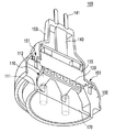
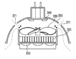
FIG. 11 is a perspective view of a lighting device according to the fourth embodiment. FIG. 12 is a bottom plan view of the illumination device according to the fourth embodiment. 13 is a cross-sectional view taken along line AA in FIG. 14 is a cross-sectional view taken along line BB in FIG.
図11ないし図14を参照すると、照明装置は、発光モジュール部520、発光モジュール部520の上に配置される中間本体510、中間本体510に結合する上部ケース550、中間本体510に結合して発光モジュール部520を固定する下部ケース560を含み得る。
Referring to FIGS. 11 to 14, the lighting device includes a light emitting
発光モジュール部520は、基板515と基板515の上に配置される発光素子517とを含み得る。
The light emitting
中間本体510は、発光モジュール部520の一側上に配置される放熱体513を含み得る。中間本体510は、発光モジュール部520の後面部に接触するように配置され、発光モジュール部520の熱が中間本体510に効率的に伝達され得る。
The
放熱体513の上には放熱ファン530が配置され、外部の空気の流れが放熱体513に伝達されるようにできる。このような空気の流れで、放熱体513の熱が外部に放出され得る。放熱ファン530は、放熱体513と離隔されて放熱体513に向かう方向に配置され得る。
A
上部ケース550は、放熱ファン530と駆動部540を覆うように配置され得る。上部ケース550は、放熱ファン530により吸入された外部空気が、空気流出口516を通して出て行くことができるように密閉空間を形成し得る。
The
下部ケース560は、図12に示されたように、空気流入口561を有し得る。図12に示された下部ケース560の面に表示されたA−A線が通り過ぎる円形点線は、下部ケース560が中間本体510などにねじ結合するためのねじ溝である。
The
下部ケース560に配置される空気流入口561の位置は変更可能であり、図12のように下部ケース560の縁部分に配置されてもよく、下部ケース560の中央に配置されてもよい。
The position of the
中間本体510には、下部ケース560の空気流入口561が配置されていない面の方向に空気流出口516が配置され得る。説明したように、空気流入口561を通して流入した空気は、上部ケース550と放熱ファン530との間に入って放熱ファン530を通過して放熱体513と熱交換をなした後、空気流出口516を通して放出され得る。
An
下部ケース560の空気流入口561は、上部ケース550と放熱ファン530の上部との間の空間につながり、空気流出口516は、放熱ファン530の下部と放熱体513との間の空間につながり得る。
The
また、空気流入口561に続く空気通路と空気流出口516に続く空気通路は、上部ケース550の隔壁及び放熱ファン530によって互いに分離され得る。
Further, the air passage following the
空気流出口516は、中間本体510の外周方向に向かう面に配置され、流入した空気が照明装置の外周方向に抜け出るようにする。この場合、空気流出口516を通して流出した空気が再び空気流入口561に流入しない。したがって、放熱体513と熱交換をなして熱くなった空気が再び照明装置の内部に流入しないので、照明装置の熱効率が向上され得る。
The
また、下部ケース560にはレンズ部570をさらに含み得る。レンズ部570は、発光モジュール部から生成される光が放出される方向に突出し、下部ケース560より高く突出した形状を有する。
Further, the
[結合が容易なレンズ部を有する変形例]
図15は、第5実施形態による照明装置の斜視図である。図16は、第5実施形態による照明装置の下部平面図である。図17は、第5実施形態による照明装置のレンズ部を示す。
[Modified example having a lens portion that can be easily coupled]
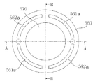
FIG. 15 is a perspective view of the illumination device according to the fifth embodiment. FIG. 16 is a bottom plan view of the illumination device according to the fifth embodiment. FIG. 17 shows a lens unit of the illumination device according to the fifth embodiment.
図15ないし図17を参照すると、照明装置は、図11ないし図14に示された照明装置と同様に、発光モジュール部(図示せず)、中間本体510、放熱ファン(図示せず)、駆動部(図示せず)、上部ケース550、下部ケース560を含み得る。この時、図15ないし図17に示された第5実施形態による照明装置はレンズ部570をさらに含み、下部ケース560がレンズ部570を固定させることができる。一実施形態において、また、下部ケース560には空気流入口561a及び空気流出口562aが配置され得る。図16に示された下部ケース560の面に表示されたA−A線が通り過ぎる円形点線は、下部ケース560が中間本体510などにねじ結合されるためのねじ溝である。そして、図11に示された中間本体510に形成された空気流出口516とは異なり、図15に示された中間本体510に形成された空気流出口562bは、中間本体510の全体に形成され得る。また、中間本体510には空気流出口562bが省略されてもよい。中間本体510、上部ケース550、中間本体510及び上部ケース550内に位置する放熱ファンを全て本体部と呼ぶこともできる。
Referring to FIGS. 15 to 17, the lighting device is similar to the lighting device shown in FIGS. 11 to 14, the light emitting module unit (not shown), the
レンズ部570は、中間本体510が配置された部分の反対側である発光モジュール部の他方を覆うように配置され得る。レンズ部570は、発光モジュール部から生成される光が放出される方向に突出し、下部ケース560より高く突出した形状を有する。
The
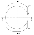
図17を参照すると、レンズ部570は、発光モジュール部から生成された光が透過する光学部571及び光学部571から外側方向に延びて配置される固定部575を含み得る。図17aは、このようなレンズ部570の平面図、図17bは図17aのA−A線による断面図、図17cは図17aのB−B線による断面図である。
Referring to FIG. 17, the
図17に示されたように、レンズ部570は、一部の方向にのみ外側方向へ延びた固定部575を有し得る。このような構成は、下部ケース560と中間本体510間の結合のための空間を確保するためのもので、これについては、上記の図13及び図14を参照して説明する。
As shown in FIG. 17, the
下部ケース560は、レンズ部570の一部の上に配置されて中間本体510にねじ結合され得る。下部ケース560はレンズ部570の一部を覆い、中間本体510に結合してレンズ部570が固定されるようにできる。
The
ねじ溝部分を通り過ぎる線A−Aを基準とした断面図である図13を参照すると、レンズ部570は、下部ケース560のねじ溝が存在する外側方向に延びた部分が存在しない。このような構成は、下部ケース560と中間本体510などのねじ結合通路を阻まないためである。ただし、ねじ溝が図16で示された場合より外側方向に配置されるならば、レンズ部570が下部ケース560のねじ溝まで外側方向に延びた部分を有することもある。
Referring to FIG. 13, which is a cross-sectional view based on the line AA passing through the thread groove portion, the
ねじ溝部分を通り過ぎない線B−Bを基準とした断面図である図14を参照すると、レンズ部570が下部ケース560の一部まで外側方向に延びた部分を有することが分かる。
Referring to FIG. 14, which is a cross-sectional view based on the line BB that does not pass through the thread groove portion, it can be seen that the
レンズ部570から外側方向に延びた固定部575は、下部ケース560と中間本体570との間に挟まれるように配置され、レンズ部570に対する直接的なねじ結合なしでもレンズ部570が固定された位置を保持するようにできる。
The fixing
上述のような構成で照明装置は、レンズ自体にねじを結合しないながらも、レンズ部が照明装置内の特定位置に固定されるようにでき、照明装置の組み立てが簡単になり、レンズ部の形成も容易になり得る。 With the configuration as described above, the illumination device can be fixed to a specific position in the illumination device without connecting a screw to the lens itself, and the assembly of the illumination device is simplified and the lens portion is formed. Can also be easier.
以上で、実施形態を中心に説明したが、これはただ例示にすぎず、本発明を限定するものではなく、本発明が属する技術分野の通常の知識を有する者であれば、本実施形態の本質的な特性を外れない範囲で、以上に例示されない様々な変形や応用が可能であることが分かるはずである。例えば、実施形態に具体的に示された各構成要素は、変形して実施することができるものである。そして、このような変形と応用に関係した相違点は、添付された請求の範囲で規定する本発明の範囲に含まれるものと解釈されるべきであるといえる。 Although the embodiment has been mainly described above, this is merely an example and does not limit the present invention. Any person having ordinary knowledge in the technical field to which the present invention belongs can be used. It should be understood that various modifications and applications not exemplified above are possible without departing from the essential characteristics. For example, each component specifically shown in the embodiment can be modified and implemented. And it can be said that the difference regarding such a deformation | transformation and application should be interpreted as being included in the range of the present invention prescribed | regulated by the attached claim.
Claims (7)
前記発光モジュール部の上に配置される中間本体と、
前記中間本体の上に配置される放熱ファンと、
前記放熱ファンの上に配置され、前記中間本体と結合する上部ケースと、
前記中間本体の下に配置され、前記中間本体と結合する下部ケースと、を含み、
前記下部ケースは、空気流入口を有し、
前記空気流入口は、前記放熱ファンと前記上部ケースとの間の第1空間とつながり、
前記中間本体は空気流出口を有し、
前記空気流出口は、前記中間本体と前記放熱ファンとの間の第2空間とつながり、
前記放熱ファンは、前記第1空間から前記第2空間の方向に風を噴射し、
空気は、前記空気流入口を通して前記第1空間に流入し、
前記第1空間内の空気は、前記放熱ファンによって前記第1空間から前記第2空間に流入し、
前記第2空間内の空気は、前記空気流出口を通して放出され、
前記中間本体は、前記空気流入口を通して流入された空気を前記第1空間に流入させるための空気通路を有し、
前記中間本体の空気通路は、前記空気流出口及び前記第2空間から分離されている、照明装置。 A light emitting module,
An intermediate body disposed on the light emitting module part;
A heat dissipating fan disposed on the intermediate body;
An upper case disposed on the heat dissipation fan and coupled to the intermediate body;
A lower case disposed under the intermediate body and coupled to the intermediate body,
The lower case has an air inlet,
The air inlet is connected to a first space between the heat radiating fan and the upper case,
The intermediate body has an air outlet;
The air outlet is connected to a second space between the intermediate body and the heat dissipating fan;
The heat dissipation fan injects wind from the first space toward the second space,
Air flows into the first space through the air inlet;
The air in the first space flows into the second space from the first space by the heat dissipation fan,
Air in the second space is released through the air outlet ;
The intermediate body has an air passage for allowing the air introduced through the air inlet to flow into the first space;
The lighting device , wherein the air passage of the intermediate body is separated from the air outlet and the second space .
前記発光モジュール部の上に配置される中間本体と、An intermediate body disposed on the light emitting module part;
前記中間本体の上に配置される放熱ファンと、A heat dissipating fan disposed on the intermediate body;
前記放熱ファンの上に配置され、前記中間本体と結合する上部ケースと、An upper case disposed on the heat dissipation fan and coupled to the intermediate body;
前記中間本体の下に配置され、前記中間本体と結合する下部ケースと、を含み、A lower case disposed under the intermediate body and coupled to the intermediate body,
前記下部ケースは、空気流入口を有し、The lower case has an air inlet,
前記空気流入口は、前記放熱ファンと前記上部ケースとの間の第1空間とつながり、The air inlet is connected to a first space between the heat radiating fan and the upper case,
前記中間本体は空気流出口を有し、The intermediate body has an air outlet;
前記空気流出口は、前記中間本体と前記放熱ファンとの間の第2空間とつながり、The air outlet is connected to a second space between the intermediate body and the heat dissipating fan;
前記放熱ファンは、前記第1空間から前記第2空間の方向に風を噴射し、The heat dissipation fan injects wind from the first space toward the second space,
空気は、前記空気流入口を通して前記第1空間に流入し、Air flows into the first space through the air inlet;
前記第1空間内の空気は、前記放熱ファンによって前記第1空間から前記第2空間に流入し、The air in the first space flows into the second space from the first space by the heat dissipation fan,
前記第2空間内の空気は、前記空気流出口を通して放出される、照明装置であって、The lighting device in which the air in the second space is discharged through the air outlet,
前記照明装置は、前記下部ケースと結合し、前記下部ケースよりさらに高く突出したレンズ部をさらに含み、The illumination device further includes a lens unit coupled to the lower case and protruding higher than the lower case,
前記レンズ部は、The lens part is
前記発光モジュール部から生成された光を透過する光学部と、An optical unit that transmits light generated from the light emitting module unit;
前記下部ケースと前記中間本体との間に配置され、前記光学部を中心に互いに分離され、かつ対称となるように、前記光学部から外側方向に延びて配置された一対の固定部と、を含む、照明装置。A pair of fixing portions disposed between the lower case and the intermediate body, separated from each other about the optical portion, and arranged to extend outward from the optical portion so as to be symmetrical; Including lighting device.
前記複数の放熱フィンは、前記放熱ファンが噴射する風の方向と垂直であり、前記空気流出口に向かう方向に配列された、請求項1又は2に記載の照明装置。 The intermediate body includes a plurality of radiating fins extending in the direction of the radiating fan,
Wherein the plurality of heat dissipating fins, the cooling fan is perpendicular to the direction of the wind injection are arranged in a direction toward the air outlet, the lighting device according to claim 1 or 2.
Applications Claiming Priority (5)
| Application Number | Priority Date | Filing Date | Title |
|---|---|---|---|
| KR10-2011-0086859 | 2011-08-30 | ||
| KR1020110086859A KR101883323B1 (en) | 2011-08-30 | 2011-08-30 | Lighting device |
| KR1020110091542A KR101890186B1 (en) | 2011-09-09 | 2011-09-09 | Lighting device |
| KR10-2011-0091542 | 2011-09-11 | ||
| PCT/KR2012/006920 WO2013032239A1 (en) | 2011-08-30 | 2012-08-30 | Lighting device |
Publications (3)
| Publication Number | Publication Date |
|---|---|
| JP2014525657A JP2014525657A (en) | 2014-09-29 |
| JP2014525657A5 JP2014525657A5 (en) | 2015-10-15 |
| JP6116567B2 true JP6116567B2 (en) | 2017-04-19 |
Family
ID=47757239
Family Applications (1)
| Application Number | Title | Priority Date | Filing Date |
|---|---|---|---|
| JP2014528280A Active JP6116567B2 (en) | 2011-08-30 | 2012-08-30 | Lighting device |
Country Status (5)
| Country | Link |
|---|---|
| US (1) | US9739469B2 (en) |
| EP (1) | EP2751473B1 (en) |
| JP (1) | JP6116567B2 (en) |
| CN (2) | CN103782081B (en) |
| WO (1) | WO2013032239A1 (en) |
Families Citing this family (6)
| Publication number | Priority date | Publication date | Assignee | Title |
|---|---|---|---|---|
| WO2012155816A1 (en) * | 2011-05-18 | 2012-11-22 | 广州南科集成电子有限公司 | Dustproof and waterproof multipurpose led-light power source assembly and dustproof and waterproof led light |
| NL1040116C2 (en) * | 2013-03-22 | 2014-09-24 | Next Generation Energy Solutions B V | Illumination device for stimulating plant growth. |
| KR101435857B1 (en) * | 2013-12-17 | 2014-09-23 | 엘지전자 주식회사 | Lighting apparatus |
| US9835321B2 (en) * | 2015-07-20 | 2017-12-05 | Paul E. Britt | LED mechanical lighting fixture |
| CN111355938A (en) * | 2018-12-24 | 2020-06-30 | 中强光电股份有限公司 | Projection device |
| KR102194231B1 (en) * | 2020-04-01 | 2020-12-23 | 주식회사 성안조명 | Waterproof tunnel lights |
Family Cites Families (30)
| Publication number | Priority date | Publication date | Assignee | Title |
|---|---|---|---|---|
| US7144140B2 (en) * | 2005-02-25 | 2006-12-05 | Tsung-Ting Sun | Heat dissipating apparatus for lighting utility |
| TWM310984U (en) * | 2006-11-28 | 2007-05-01 | Primo Lite Co Ltd | Lamp structure of light emitting diode |
| EP1998108B1 (en) | 2007-05-30 | 2015-04-29 | OSRAM GmbH | Cooling apparatus |
| TWM332793U (en) * | 2007-11-28 | 2008-05-21 | Cooler Master Co Ltd | Heat radiating structure and the lighting apparatus |
| TW200940881A (en) * | 2008-03-18 | 2009-10-01 | Pan Jit Internat Inc | LED lamp with thermal convection and thermal conduction heat dissipating effect, and heat dissipation module thereof |
| TWM346745U (en) | 2008-07-25 | 2008-12-11 | Forcecon Technology Co Ltd | LED Lamp with heat-dissipation toward the terminal direction |
| JP2010040221A (en) | 2008-07-31 | 2010-02-18 | Toshiba Lighting & Technology Corp | Self-ballasted lamp |
| EP2154419B1 (en) | 2008-07-31 | 2016-07-06 | Toshiba Lighting & Technology Corporation | Self-ballasted lamp |
| US8143769B2 (en) * | 2008-09-08 | 2012-03-27 | Intematix Corporation | Light emitting diode (LED) lighting device |
| US8240885B2 (en) * | 2008-11-18 | 2012-08-14 | Abl Ip Holding Llc | Thermal management of LED lighting systems |
| JP2010153198A (en) | 2008-12-25 | 2010-07-08 | Nec Lighting Ltd | Luminaire |
| TWI366645B (en) | 2009-03-24 | 2012-06-21 | Young Green Energy Co | Illumination apparatus |
| KR20100114789A (en) | 2009-04-16 | 2010-10-26 | (주)대영오앤이 | Lighting apparatus using light-emitting diode with radiant heating means |
| US20100295436A1 (en) * | 2009-05-19 | 2010-11-25 | Alex Horng | Lamp |
| CA2767662A1 (en) * | 2009-07-06 | 2011-01-13 | Edward T. Rodriguez | Cooling solid state high-brightness white-light illumination sources |
| TWM372923U (en) * | 2009-08-14 | 2010-01-21 | Risun Expanse Corp | Lamp structure |
| TWI376481B (en) * | 2009-10-13 | 2012-11-11 | Sunonwealth Electr Mach Ind Co | Lamp |
| US9068733B2 (en) | 2010-01-09 | 2015-06-30 | David M. Medinis | LED lamp with actively cooled heat sink |
| US8525395B2 (en) * | 2010-02-05 | 2013-09-03 | Litetronics International, Inc. | Multi-component LED lamp |
| CN201706458U (en) * | 2010-05-27 | 2011-01-12 | 建准电机工业股份有限公司 | Lamp and radiator thereof |
| KR101370920B1 (en) * | 2010-06-23 | 2014-03-07 | 엘지전자 주식회사 | Lighting Device |
| KR101285889B1 (en) * | 2010-06-23 | 2013-07-11 | 엘지전자 주식회사 | LED Lighting Device |
| KR101349841B1 (en) * | 2010-06-24 | 2014-01-09 | 엘지전자 주식회사 | LED Lighting Device |
| US8480269B2 (en) * | 2010-07-07 | 2013-07-09 | Sunonwealth Electric Machine Industry Co., Ltd. | Lamp and heat sink thereof |
| TWI397650B (en) * | 2010-09-15 | 2013-06-01 | Sunonwealth Electr Mach Ind Co | Lamp |
| TWI457518B (en) * | 2010-12-13 | 2014-10-21 | Sunonwealth Electr Mach Ind Co | Lamp |
| US9470882B2 (en) * | 2011-04-25 | 2016-10-18 | Cree, Inc. | Optical arrangement for a solid-state lamp |
| US20120287651A1 (en) * | 2011-05-09 | 2012-11-15 | Panasonic Corporation | Illumination apparatus and fan unit for illumination apparatus |
| JP6057543B2 (en) * | 2011-05-23 | 2017-01-11 | エルジー イノテック カンパニー リミテッド | Lighting device |
| KR101414650B1 (en) * | 2012-05-09 | 2014-07-03 | 엘지전자 주식회사 | Lighting apparatus |
-
2012
- 2012-08-30 CN CN201280042436.6A patent/CN103782081B/en active Active
- 2012-08-30 JP JP2014528280A patent/JP6116567B2/en active Active
- 2012-08-30 CN CN201610883790.1A patent/CN107023762B/en active Active
- 2012-08-30 US US14/240,317 patent/US9739469B2/en active Active
- 2012-08-30 WO PCT/KR2012/006920 patent/WO2013032239A1/en active Application Filing
- 2012-08-30 EP EP12829045.9A patent/EP2751473B1/en active Active
Also Published As
| Publication number | Publication date |
|---|---|
| JP2014525657A (en) | 2014-09-29 |
| CN103782081B (en) | 2016-11-09 |
| EP2751473B1 (en) | 2019-10-02 |
| US9739469B2 (en) | 2017-08-22 |
| CN103782081A (en) | 2014-05-07 |
| CN107023762A (en) | 2017-08-08 |
| WO2013032239A1 (en) | 2013-03-07 |
| CN107023762B (en) | 2020-12-11 |
| EP2751473A1 (en) | 2014-07-09 |
| EP2751473A4 (en) | 2015-01-07 |
| US20140211478A1 (en) | 2014-07-31 |
Similar Documents
| Publication | Publication Date | Title |
|---|---|---|
| JP6057543B2 (en) | Lighting device | |
| JP5756502B2 (en) | Lighting device | |
| JP5101578B2 (en) | Light emitting diode lighting device | |
| JP6116567B2 (en) | Lighting device | |
| JP2010135181A (en) | Illuminating device | |
| JP6196330B2 (en) | Lamp device | |
| TW201221830A (en) | LED light device with improved thermal and optical characteristics | |
| JP2012069396A (en) | Lighting unit and lighting system | |
| KR101842583B1 (en) | Lighting device | |
| KR101833221B1 (en) | Lighting device | |
| KR101890186B1 (en) | Lighting device | |
| KR101883323B1 (en) | Lighting device | |
| KR101868470B1 (en) | Lighting device | |
| KR101833223B1 (en) | Lighting device | |
| KR20120130365A (en) | Lighting device | |
| KR20130115860A (en) | Lighting device | |
| TWI530646B (en) | Multi - layer array - shaped light - emitting diode light engine multi - layer heat dissipation structure | |
| TWI421437B (en) | Led lamp | |
| KR20130115714A (en) | Lighting device | |
| JP2011129469A (en) | Lighting fixture | |
| TWM406705U (en) | LED lamp assembly | |
| TW201326662A (en) | LED lighting device | |
| JP2011129470A (en) | Lighting fixture | |
| JP2013125631A (en) | Lighting apparatus | |
| TW201337162A (en) | Light-emitting diode bulb |
Legal Events
| Date | Code | Title | Description |
|---|---|---|---|
| A521 | Request for written amendment filed |
Free format text: JAPANESE INTERMEDIATE CODE: A523 Effective date: 20150828 |
|
| A621 | Written request for application examination |
Free format text: JAPANESE INTERMEDIATE CODE: A621 Effective date: 20150828 |
|
| A977 | Report on retrieval |
Free format text: JAPANESE INTERMEDIATE CODE: A971007 Effective date: 20160614 |
|
| A131 | Notification of reasons for refusal |
Free format text: JAPANESE INTERMEDIATE CODE: A131 Effective date: 20160621 |
|
| A521 | Request for written amendment filed |
Free format text: JAPANESE INTERMEDIATE CODE: A523 Effective date: 20160915 |
|
| TRDD | Decision of grant or rejection written | ||
| A01 | Written decision to grant a patent or to grant a registration (utility model) |
Free format text: JAPANESE INTERMEDIATE CODE: A01 Effective date: 20170307 |
|
| A61 | First payment of annual fees (during grant procedure) |
Free format text: JAPANESE INTERMEDIATE CODE: A61 Effective date: 20170321 |
|
| R150 | Certificate of patent or registration of utility model |
Ref document number: 6116567 Country of ref document: JP Free format text: JAPANESE INTERMEDIATE CODE: R150 |
|
| R250 | Receipt of annual fees |
Free format text: JAPANESE INTERMEDIATE CODE: R250 |
|
| R250 | Receipt of annual fees |
Free format text: JAPANESE INTERMEDIATE CODE: R250 |
|
| S531 | Written request for registration of change of domicile |
Free format text: JAPANESE INTERMEDIATE CODE: R313531 |
|
| S111 | Request for change of ownership or part of ownership |
Free format text: JAPANESE INTERMEDIATE CODE: R313113 |
|
| R350 | Written notification of registration of transfer |
Free format text: JAPANESE INTERMEDIATE CODE: R350 |
|
| R350 | Written notification of registration of transfer |
Free format text: JAPANESE INTERMEDIATE CODE: R350 |
|
| R250 | Receipt of annual fees |
Free format text: JAPANESE INTERMEDIATE CODE: R250 |
|
| R250 | Receipt of annual fees |
Free format text: JAPANESE INTERMEDIATE CODE: R250 |