JP6116261B2 - Barrier device, lens barrel, and imaging device including the same - Google Patents
Barrier device, lens barrel, and imaging device including the same Download PDFInfo
- Publication number
- JP6116261B2 JP6116261B2 JP2013012999A JP2013012999A JP6116261B2 JP 6116261 B2 JP6116261 B2 JP 6116261B2 JP 2013012999 A JP2013012999 A JP 2013012999A JP 2013012999 A JP2013012999 A JP 2013012999A JP 6116261 B2 JP6116261 B2 JP 6116261B2
- Authority
- JP
- Japan
- Prior art keywords
- barrier
- shielding member
- closed state
- shielding
- lens
- Prior art date
- Legal status (The legal status is an assumption and is not a legal conclusion. Google has not performed a legal analysis and makes no representation as to the accuracy of the status listed.)
- Expired - Fee Related
Links
- 230000004888 barrier function Effects 0.000 title claims description 247
- 238000003384 imaging method Methods 0.000 title claims description 7
- 230000003287 optical effect Effects 0.000 claims description 23
- 230000007704 transition Effects 0.000 claims description 15
- 230000013011 mating Effects 0.000 claims description 4
- 230000002093 peripheral effect Effects 0.000 description 27
- 230000009471 action Effects 0.000 description 11
- 238000010586 diagram Methods 0.000 description 3
- 230000008878 coupling Effects 0.000 description 2
- 238000010168 coupling process Methods 0.000 description 2
- 238000005859 coupling reaction Methods 0.000 description 2
- 238000005034 decoration Methods 0.000 description 2
- 238000001514 detection method Methods 0.000 description 2
- 230000000694 effects Effects 0.000 description 2
- 230000007246 mechanism Effects 0.000 description 2
- 230000000149 penetrating effect Effects 0.000 description 2
- 230000002787 reinforcement Effects 0.000 description 2
- 239000000853 adhesive Substances 0.000 description 1
- 230000001070 adhesive effect Effects 0.000 description 1
- 230000008859 change Effects 0.000 description 1
- 239000011521 glass Substances 0.000 description 1
- 238000007562 laser obscuration time method Methods 0.000 description 1
- 238000005096 rolling process Methods 0.000 description 1
- 230000009466 transformation Effects 0.000 description 1
Images


Classifications
-
- G—PHYSICS
- G03—PHOTOGRAPHY; CINEMATOGRAPHY; ANALOGOUS TECHNIQUES USING WAVES OTHER THAN OPTICAL WAVES; ELECTROGRAPHY; HOLOGRAPHY
- G03B—APPARATUS OR ARRANGEMENTS FOR TAKING PHOTOGRAPHS OR FOR PROJECTING OR VIEWING THEM; APPARATUS OR ARRANGEMENTS EMPLOYING ANALOGOUS TECHNIQUES USING WAVES OTHER THAN OPTICAL WAVES; ACCESSORIES THEREFOR
- G03B9/00—Exposure-making shutters; Diaphragms
- G03B9/08—Shutters
- G03B9/10—Blade or disc rotating or pivoting about axis normal to its plane
- G03B9/14—Two separate members moving in opposite directions
-
- G—PHYSICS
- G03—PHOTOGRAPHY; CINEMATOGRAPHY; ANALOGOUS TECHNIQUES USING WAVES OTHER THAN OPTICAL WAVES; ELECTROGRAPHY; HOLOGRAPHY
- G03B—APPARATUS OR ARRANGEMENTS FOR TAKING PHOTOGRAPHS OR FOR PROJECTING OR VIEWING THEM; APPARATUS OR ARRANGEMENTS EMPLOYING ANALOGOUS TECHNIQUES USING WAVES OTHER THAN OPTICAL WAVES; ACCESSORIES THEREFOR
- G03B11/00—Filters or other obturators specially adapted for photographic purposes
- G03B11/04—Hoods or caps for eliminating unwanted light from lenses, viewfinders or focusing aids
- G03B11/043—Protective lens closures or lens caps built into cameras
Description
本発明は、バリア装置、レンズ鏡筒およびそれを備える撮像装置に関する。 The present invention relates to a barrier device, a lens barrel, and an imaging device including the same.
撮影レンズの前面に設けられたバリア装置(バリア機構)を備えるレンズ鏡筒が提案されている。バリア装置は、撮像装置の沈胴状態または撮影状態への移行にともなって、撮影レンズを遮蔽または開口する。例えば、撮影レンズ前面に開閉可能に取り付けられた大小2対の羽根部材を有するバリア部材と、バリア部材を開閉させるバリア駆動手段とを備えたバリア機構が提案されている。 There has been proposed a lens barrel including a barrier device (barrier mechanism) provided in front of the photographing lens. The barrier device shields or opens the photographing lens as the imaging device shifts to the retracted state or the photographing state. For example, a barrier mechanism including a barrier member having two pairs of large and small blade members attached to the front surface of the photographing lens so as to be openable and closable and barrier driving means for opening and closing the barrier member has been proposed.
特許文献1は、第1、第2の羽根部材と、駆動部材に設けられた第1、第2の係合部と、第1、第2の付勢部材とを備えるカメラのバリア装置を開示している。 Patent Document 1 discloses a camera barrier device including first and second blade members, first and second engaging portions provided on a driving member, and first and second urging members. doing.
しかし、特許文献1が開示しているバリア装置では、バリア主羽根、バリア副羽根のそれぞれに対応する閉じバネが必要であり、部品点数が増加してしまう。また、このバリア装置では、バネバランスの設定が必要となり、複雑な構造になってしまう。また、このバリア装置では、バリアの開閉において、バリア主羽根とバリア副羽根との間で不必要な摩擦が発生する。さらに、このバリア装置では、レンズが広角化してくると、バリア開口径が大きくなり、羽根部材および開きバネのスペースが減少してしまい、羽根部材の回転軸の嵌合長が取れなくなるため、組立時に羽根部材が外れやすくなってしまう。 However, the barrier device disclosed in Patent Document 1 requires a closing spring corresponding to each of the barrier main blade and the barrier sub blade, which increases the number of components. Further, in this barrier device, it is necessary to set a spring balance, resulting in a complicated structure. In this barrier device, unnecessary friction is generated between the barrier main blade and the barrier sub blade when the barrier is opened and closed. Further, in this barrier device, when the lens is widened, the barrier opening diameter is increased, the space of the blade member and the opening spring is reduced, and the fitting length of the rotating shaft of the blade member cannot be obtained. Sometimes the blade member is easily detached.
本発明は、上記の課題の少なくとも一つを解決するためになされたものである。本発明は、部品点数を削減でき、簡単な構成でバリアの開閉動作を可能とするバリア装置の提供を目的とする。 The present invention has been made to solve at least one of the above problems. It is an object of the present invention to provide a barrier device that can reduce the number of parts and can open and close the barrier with a simple configuration.
本発明の一実施形態のバリア装置は、レンズを遮蔽する閉状態と前記レンズを露出する開状態との間で遷移する第1および第2の遮蔽部材と、前記第1および第2の遮蔽部材を駆動して、前記閉状態または開状態に遷移させる駆動部材とを備える。前記第2の遮蔽部材が備える、前記第1の遮蔽部材との第1の当接面の一部が、前記開状態または前記閉状態のいずれかの状態において、前記第1の遮蔽部材が備える、前記第2の遮蔽部材との第2の当接面の作動範囲内に位置し、前記第1の遮蔽部材と前記第2の遮蔽部材は、互いに逆方向に回動する。 The barrier device according to an embodiment of the present invention includes first and second shielding members that transition between a closed state that shields a lens and an open state that exposes the lens, and the first and second shielding members. And a drive member that transitions to the closed state or the open state. A part of the first contact surface with the first shielding member provided in the second shielding member is provided in the first shielding member in either the open state or the closed state. The first shielding member and the second shielding member are rotated in opposite directions to each other, and are located within the operating range of the second contact surface with the second shielding member .
本発明のバリア装置によれば、部品点数を削減でき、簡単な構成でバリアの開閉動作が可能なる。 According to the barrier device of the present invention, the number of parts can be reduced, and the barrier can be opened and closed with a simple configuration.
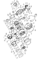
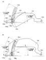
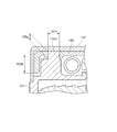
以下に、図1乃至図3を参照して、本実施形態のバリア装置を含むレンズ鏡筒の構成例について説明する。図1は、レンズ鏡筒の分解斜視図の例である。図2は、撮影状態におけるレンズ鏡筒の断面図の例である。図3は、沈胴状態におけるレンズ鏡筒の断面図の例である。本実施形態の撮像装置は、図1乃至3が示すレンズ鏡筒を備える。 Hereinafter, a configuration example of a lens barrel including the barrier device of the present embodiment will be described with reference to FIGS. 1 to 3. FIG. 1 is an example of an exploded perspective view of a lens barrel. FIG. 2 is an example of a cross-sectional view of the lens barrel in the photographing state. FIG. 3 is an example of a sectional view of the lens barrel in the retracted state. The imaging apparatus of this embodiment includes a lens barrel shown in FIGS.
第1レンズ群100は、第1レンズ101と、第1レンズ101を保持する円筒状の第1レンズ枠102を有する。第1レンズ枠102の内周面には、径方向内側に突出すると共に、内周方向において等角度の間隔で設けられたカムピン102aと、第1レンズ群100を回転規制するキー溝1とが設けられている。また、外周面には、バリア群を回転規制するキー溝102cが等角度の間隔で設けられている。なお、本実施形態では、第1レンズ101と第1レンズ枠102とは別体構成となっているが、一体構成でもかまわない。
The
バリア群150は、本実施形態のバリア装置である。バリア群150は、バリア筒151、バリアドライブリング152、バリア開きバネ153、バリア主羽根154、バリア副羽根155、キャップテープ156、キャップ157を備える。キャップ157は、キャップテープ156により、バリア筒151の被写体側へ取り付けられるカバー部材である。
The
バリア筒151の内周面には、径方向内側に突出すると共に、内周方向において等角度の間隔で設けられたカムピン151aと、バリア群150を回転規制する直進キー151bとが設けられている。
On the inner peripheral surface of the
第2レンズ群200は、第2レンズ201と、第2レンズ201を保持する円筒状の第2レンズ枠202を有する。第2レンズ枠202の外周面には、径方向外側に突出すると共に、外周方向において等角度の間隔で設けられたカムピン202aと、第2レンズ群200を回転規制する直進キー202bとが設けられている。
The
第3レンズ群300には、3群ベース303の結像面側に、光量調整部材であるシャッター羽根310、NDフィルター312、セパレートシート311、シャッターカバー313、シャッターアクチュエータが設けられている。3群ベース303の被写体側には、像振れ補正用コイル304、転動ボール305、第3レンズ枠302、第3レンズ301、バネ306、キャップ307が設けられている。また、3群ベース303の被写体側には、像振れ補正ホルダー308、FPC309、およびFPC309に固定された位置検出センサ316が設けられている。第3レンズ枠302は、第3レンズ301を保持する。また、第3レンズ枠302には、被写体側に、光量を規制するキャップ307が取り付けられる。
The
また、第3レンズ枠302は、像振れ補正用マグネット315を保持している。また第3レンズ枠302はボール305、バネ306の作用により、3群ベースに移動可能に保持される。また、第3レンズ枠302は、像振れ補正用コイル304および像振れ補正用マグネット315の作用により発生する駆動力により、撮像光学系の光軸に直交する方向の任意の位置へ移動し、位置検出センサ316により位置制御される。
The
第1レンズ枠102の内側には、直進筒602が設けられている。直進筒602は、カム筒401に対して回動自在であるとともに、直進プレート604に回転規制されるい。また、直進筒602は第1レンズ群100、第2レンズ群200、第3レンズ群300の回転を規制し、第1レンズ群100、第2レンズ群200、第3レンズ群300の光軸方向への移動を直進案内する。
A
直進筒602の外周面には、キー溝602dが設けられている。キー溝602dは、直進プレート604の直進キー604aと嵌合すると共に、直進プレート604を回転規制する。また、直進筒602の被写体側には、直進キー602aが設けられている。直進キー602aは、第1レンズ枠102のキー溝102bと嵌合する。
A
また、直進筒602の内周面には、第2レンズ枠202の直進キー202bを回転規制するための貫通したキー溝602b、3群ベース303の直進キー303bを回転規制するための貫通したキー溝602cが等角度間隔で設けられている。直進筒602の結像面側には、有害光を遮断する遮光板603が取り付けられる。
Further, on the inner peripheral surface of the
直進筒602の外周面は、カム筒601の内面と嵌合する。また、直進筒602の外周面は、カム筒601とバヨネット結合することで、カム筒601と相対的に回転可能に保持される。
The outer peripheral surface of the
直進プレート604には、光軸方向に伸びた直進筒602のキー溝602dと嵌合する直進キー604a、およびカバー筒503のキー溝と嵌合する直進キー604bが設けられている。また、円弧上の外周部は、カムカバー501とバヨネット結合することで、カムカバー501と相対的に回転可能に保持される。また、この外周部には、固定筒701の内周面に設けられたキー溝701aと嵌合し、直進規制される直進キー604cが等角度間隔に設けられている。
The
カム筒601の外周には、カバー筒503が設けられている。カバー筒503は、直進プレート604に回転規制され、カムカバー501により光軸方向に進退する。カバー筒503の内周面には、直進プレート604の直進キー604bと嵌合するキー溝が設けられている。また、カバー筒503の外周面には、カムピン503aが設けられている。カムピン503aは、カバー筒503の外周方向において等角度の間隔で設けられ、カバー筒503の径方向外側に突出すると共に、カムカバー501内面に設けられたカム溝501bに挿入される。また、カバー筒503の被写体側には、カムカバー501の補強と装飾を兼ねるカムカバーリング504が取り付けられる。
A
カムカバー501の外周面には、カムピン501aと、第5ギアと連結するギア部501cとが設けられている。カムピン501aはカムカバー501の外周方向において等角度の間隔で設けられ、カムカバー501の径方向外側に突出すると共に、固定筒701の内周面に設けられたカム溝701bに挿入される。カムカバー501の内周面には、カバー筒503のカムピン503aが挿入されるカム溝501bが等角度間隔に設けられている。また、この内周面には、カム筒601の回転キー601eと嵌合するキー溝が設けられている。また、カムカバー501の被写体側には、カム筒601の補強と装飾を兼ねるカム筒リング502が取り付けられる。
A
カム筒601の内周面には、第2レンズ枠202のカムピン202aが挿入されるカム溝601c、および3群ベース303のカムピン303aが挿入されるカム溝601dが、等角度の間隔で設けられている。
A
カム筒601の外周面には、第1レンズ枠102のカムピン102aが挿入されるカム溝601a、およびバリア筒151のカムピン151aが挿入されるカム溝601bが等角度間隔で設けられている。また、この外周面には、カムカバー501のキー溝と嵌合する回転キー601eが設けられている。
A
カム筒601は、カバー筒503とバヨネット結合しており、直進筒602、直進プレート604、カムカバー501の作用により、カバー筒503と回転可能に保持される。また、カム筒601は、カムカバー501の作用により光軸方向へ進退する。カバー筒503の外周には固定筒701が配置する。
The
固定筒701の内周面には,直進プレート604の直進キー604cと嵌合し、回転規制するキー溝701a、およびカムカバー501のカムピン501aが挿入されるカム溝701bが、等角度の間隔で設けられている。また、固定筒701の被写体側には、レンズ鏡筒内への異物侵入を防止する防砂シート704が配置される。
On the inner peripheral surface of the fixed
センサーホルダー700は、第4レンズ群400の駆動源410、第4レンズ群400のメインガイド404、レンズ鏡筒の駆動源703、駆動源703の動力をカムカバー501へ伝えるギア711乃至ギア715を保持する。
The
ギア711乃至ギア714は、ギアカバー702によりセンサーホルダー700に保持される。なお、ギアカバー702には、部材720がねじ730によって取り付けられている。第5ギアとしてのギア715は固定筒701とセンサーホルダー700に保持される。
The
第4レンズ群400は、第4レンズ401と第4レンズ保持枠402とを備える。第4レンズ群400は、メインガイド404、センサーホルダー700に設けられたサブガイド700aにより回転規制される。また、第4レンズ群400は、駆動源410に設けられたスクリュー411と螺合する。そして、第4レンズ群400は、駆動源410の回転により光軸方向へ進退するナット412と、レンズ枠402とナット412を当接させるスプリング403の効果により、光軸方向へ移動可能な状態で配置されている。
The
撮像素子800をセンサーホルダー700に固定する際、センサーラバー810の弾性を利用し、保護ガラス820をセンサーホルダー700に押しつけるように固定する。センサーホルダー700と固定筒701とを、ねじ840で固定することで、レンズ鏡筒をユニット化している。なお、図2中の符号830は、撮像素子裏側のねじである。また、符号740は、フレキシブルプリント基板である。
When the
ここで、レンズ鏡筒が沈胴状態から撮影状態に移行するとき、まず、駆動源703の動力によりギア711乃至715が回転し、カムカバー501が回転駆動する。カムカバー501は、固定筒701の内側と嵌合しており、その内側に設けられたカム溝701bの作用により、光軸方向へ回転しながら繰り出される。カムカバー501が回転すると、カム筒601は、カムカバー501、直進プレート604、直進筒602、カバー筒602の作用により、光軸方向へ回転しながら繰り出される。
Here, when the lens barrel shifts from the retracted state to the photographing state, first, the
直進筒602は、バヨネット結合により、カム筒601に相対的に回転可能な状態で保持されている。また、直進筒602は直進プレート604により回転規制されているため、カム筒601が回転すると、直進筒602は光軸方向へ直進移動しながら繰り出される。
The
カム筒601にカム結合している第1レンズ群100、バリア群150、第2レンズ群200、第3レンズ群300は、カム筒601と直進筒602の作用により、光軸方向へ直進移動しながら繰り出される。
The
また、第4レンズ群400は、駆動源410に設けられたスクリュー411とナット412の作用により光軸方向へ移動可能な状態で保持される。また、第4レンズ群400は、メインガイド404、サブガイド700aにより回転規制されており、カム筒601の移動とは関係なく、独立して光軸方向へ直進移動しながら繰り出される。
The
以上の構成により、カムカバー501が回転することで、各レンズ群が沈胴位置から被写体側に向けて繰り出すことでレンズ鏡筒が沈胴状態から撮影状態へと移行する。
With the above configuration, when the
なお、レンズ鏡筒は、固定筒701、カムカバー501、カム筒601の作用により、適宜相互間の距離が調整されてズーミングが行われる。
The lens barrel is zoomed by adjusting the distance between them appropriately by the action of the fixed
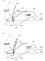
次に、図4乃至図10を参照して、本実施形態におけるバリアの開閉動作について説明する。図4は、閉状態と開状態におけるバリア主羽根とバリア副羽根との位置関係を説明する図である。図4(A)が、閉状態におけるバリア主羽根とバリア副羽根との位置関係を示す。図4(B)が、開状態におけるバリア主羽根とバリア副羽根との位置関係を示す。図5は、バリア群の分解斜視図の例である。図6は、閉状態におけるバリア群の斜視図である。図7は、閉状態におけるバリア群の斜視図である。図8は、開状態におけるバリア群の正面図である。図9は、バリア群の閉状態から開状態への動作を説明する図である。図10は、閉状態におけるバリア群の正面図である。 Next, referring to FIGS. 4 to 10, the opening / closing operation of the barrier in this embodiment will be described. FIG. 4 is a view for explaining the positional relationship between the barrier main blade and the barrier sub blade in the closed state and the open state. FIG. 4A shows the positional relationship between the barrier main blade and the barrier sub blade in the closed state. FIG. 4B shows the positional relationship between the barrier main blade and the barrier sub blade in the open state. FIG. 5 is an example of an exploded perspective view of the barrier group. FIG. 6 is a perspective view of the barrier group in the closed state. FIG. 7 is a perspective view of the barrier group in the closed state. FIG. 8 is a front view of the barrier group in the open state. FIG. 9 is a diagram for explaining the operation of the barrier group from the closed state to the open state. FIG. 10 is a front view of the barrier group in the closed state.
バリア筒151には、被写体側の光軸を挟んで対向する2箇所に、バリア主羽根154の回転軸154aが挿入される回転穴151cと、バリア副羽根155の回転穴155aに挿入される回転軸151dとが設けられている。
In the
第1の遮蔽部材であるバリア主羽根154は、レンズ(一群レンズ101)を遮蔽する閉状態とレンズを露出する開状態との間で遷移する。バリア主羽根154には、回転軸154a、バネ係止部154b、平面部154c、当接面154dが設けられている。平面部154cは、バリアドライブリング152の当接部152bと接する。当接面154dは、バリア副羽根の当接面155bと当接する。当接面155bは、第1の当接面として機能し、当接面154dは、第2の当接面として機能する。バリア主羽根154は、回転軸154aが、バリア筒151の回転穴151cに挿入されることで、バリア筒151に回転可能に保持される。
The barrier
第2の遮蔽部材であるバリア副羽根155は、レンズ(一群レンズ101)を遮蔽する閉状態とレンズを露出する開状態との間で遷移する。バリア副羽根155には、バリア筒151に設けられた回転軸151dが挿入される回転穴155a、およびバリア主羽根154の当接面154dと接する当接面155bが設けられている。バリア副羽根155は、回転穴155aにバリア筒151の回転軸151dが挿入されることで、バリア筒151に回転可能に保持される。すなわち、バリア筒151は、バリア主羽根154およびバリア副羽根155を回転可能に保持する遮蔽筒として機能する。
The
バリアドライブリング152は、カム筒601の回転に連動して回転するように、バリア筒151の前面部分にバヨネット結合により回動可能に装着され、カム筒601の回転に連動して回動する。また、バリアドライブリング152には、周方向に突出し、光軸を挟んで対向する2箇所に、バネ掛け部152a、バリア主羽根154との当接部152bが設けられている。
The
バリアドライブリング152は、カム筒601の回転に連動して回転するように、バリア筒151の前面部分に回動可能に装着されている。また、バリアドライブリング152には、その直径方向に対応する2箇所に、バネ掛け部152aが突設されている。
The
バリア主羽根154のバネ係止部154bと、バリアドライブリング152のバネ掛け部152aとの間に、開きバネ153が架設されている。開きバネ153は、引張コイルバネ(例えば、コイルスプリング)である。このように構成することにより、バリアドライブリング152には、開きバネ153により、バリア主羽根154に対して図6中の矢印010に示すようにバリア主羽根154が開く方向(バリア開方向)に回転力が与えられる。
An
バリア主羽根154およびバリア副羽根155は、共に同形状の2組の羽根を用いて沈胴時に一群レンズ101の前面を覆うように構成されている。バリア主羽根部154は、その回転軸154aがバリア筒151の前面に設けられた回転穴151cと嵌合し、回転軸154aを中心に回転して開閉動作可能に装着される。また、バリア副羽根155は、その回転穴155aがバリア筒151の前面に設けられた回転軸151dと嵌合し、回転軸151dを中心に回転して開閉動作可能に装着される。
The barrier
次に、レンズ鏡筒におけるバリア主羽根154およびバリア副羽根155を開閉するための構成について、詳細に説明する。
Next, a configuration for opening and closing the barrier
バリアドライブリング152は、略円環状に形成されており、その外周面上からL字型状に折曲して延出された連動部152cが一体的に設けられている。連動部152cには、レンズ鏡筒の沈胴時に、カム筒601前方(被写体側)に設けられたバリア駆動部601fが当接される。バリアが閉状態から開状態へ移行するとき、バリアドライブリング152の連動部152cは、開きバネ153の開き付勢力によりバリア駆動部601fに当接しながら、図6の矢印010が示すバリア開方向へ回転させる。
The
バリアドライブリング152には、当接面152bが設けられている。バリア開動作時に当接面152bがバリア主羽根154の平面部154cと当接する。これにより、バリアドライブリング152の回転動作がバリア主羽根154に伝達され、バリア主羽根154は図8中の矢印011が示す方向へ開動する。
The
一方、バリア副羽根155が、閉じ状態から開き状態へ移行するとき、バリア主羽根154との合わせ面155cがバリア主羽根154の先端部154eに押しのけられる。これにより、バリア副羽根155が、図8中の矢印012が示す方向へ開動する。本実施例においてはバリア副羽根155は回転付勢されていないので、バリア主羽根154の開動作を妨げることなく閉じ状態から開き動作へ移行する。例えば、バリア主羽根154、バリア副羽根155は、図9(A)が示す閉状態から、図9(B)、図9(C)に示す状態に順次移行し、最終的に図9(D)に示す開状態となる。つまり、バリア副羽根155は、合わせ面155cが、バリアドライブリング152により開状態になるように回動するバリア主羽根154の先端部に押されることによって回動して、閉状態から前記開状態に遷移する。したがって、バリアドライブリング152は、バリア主羽根154、バリア副羽根155を駆動して、閉状態または開状態に遷移させる駆動部材として機能する。
On the other hand, when the
ここで、バリア副羽根155の回転穴155a付近には、バリア主羽根154の羽根先端部に設けられた当接面154dと当接する当接面155bが設けられている。そのため、バリア羽根の開閉動作中は、バリア主羽根154の開動作によりバリア副羽根155が押し開けられても、当接面155bがストッパーの役割を果たすため、開きすぎることはない。
Here, in the vicinity of the
バリア開状態の時、バリア主羽根154は開きバネ153の作用により、バリア主羽根154のストッパー154fとバリア筒151のストッパー151eが当接し、開状態を保持する。
When the barrier is in the open state, the barrier
バリア副羽根155は、バリア主羽根154の先端部154eとバリア筒に設けられたストッパー部151fの間で、バリア主羽根154に付勢されることなく回動可能な状態で保持される。これにより、開状態が維持される。
The
次に、バリアが開状態から閉状態へ移行するとき、カム筒601のバリア駆動部601fは、開きバネ153の開き方向付勢力に抗しながら、バリアドライブリング152を、閉まる方向(バリア閉方向、図7中の矢印015方向)へ回転させる。すなわち、カメラの沈胴動作時に、駆動源703から伝達された回転駆動力により回転されたカム筒601のバリア駆動部601fが、連動部152cを押してバリアドライブリング152をバリア閉方向へ回転させる。このとき、平面部154cとバリアドライブリング152の当接面152bが、バリア開きバネ153の付勢力により当接している。したがって、バリア主羽根154は、バリアドライブリング152の回転動作に連動しながら、閉まる方向(バリア閉方向、図10の矢印016方向)へと回転する。
Next, when the barrier shifts from the open state to the closed state, the
図1(A)及び(B)に示すとおり、バリア主羽根154、バリア副羽根155の作動範囲内154h、155eにおいて、バリア副羽根155の当接面155bの一部がバリア主羽根154の当接面154dの作動範囲内154hに位置する。そのため、バリア副羽根155は、バリア主羽根作動範囲154hのどの位置にいても、バリア主羽根154の当接面154dに当接面155bが押される形で、閉まる方向(バリア閉方向、図10の矢印017方向)へと回転する。すなわち、バリア副羽根155は、当接面155bが、バリアドライブリング152により閉状態になるように回動するバリア主羽根154の当接面154dに押されることによって回動して、開状態から閉状態に遷移する。
As shown in FIGS. 1A and 1B, in the
以上の一連の動作により、バリア主羽根154およびバリア副羽根155は、レンズ鏡筒のズーミングに連動して開閉可能となる。
Through the series of operations described above, the barrier
図11は、バリア主羽根の作動範囲内にバリア副羽根の当接面の一部が位置しない構成を示す図である。図11(A)が示す当接部形状では、当接面155bと当接面154dは、開位置付近155fでは当接するためバリア副羽根155を閉じ方向へと回動できるが、閉位置付近155gでは当接できず、バリア副羽根155は閉状態を維持できなくなってしまう。また、図11(B)が示す当接部形状では、当接面155bと当接面154dは、閉位置付近155gでは当接するためバリア副羽根155を閉じ状態で保持できるが、開位置付近155fでは当接しない。したがって、バリア副羽根155を閉状態へと移行できなくなってしまう。
FIG. 11 is a diagram illustrating a configuration in which a part of the contact surface of the barrier sub blade is not located within the operating range of the barrier main blade. In the contact portion shape shown in FIG. 11A, the
一方、本実施形態では、図11を参照して説明したように、バリア副羽根155の当接面155bの一部が、バリア主羽根154の当接面154dの作動範囲内154hに位置する。したがって、バリア副羽根155は、バリア主羽根作動範囲154hのどの位置にいても、開状態から閉状態へと移行することができる。
On the other hand, in this embodiment, as described with reference to FIG. 11, a part of the
また、バリア副羽根155は、開状態または閉状態のいずれにおいても、バリア主羽根154の当接面154dの上部(光軸方向被写体側)に位置している。これにより、バリア副羽根155に外力が加わっても、第1レンズ101側に落ち込むことはない。
Further, the
さらに、バリア閉じ状態では、バリア主羽根154の先端部154eが、バリア副羽根155の当接面155bの上部(光軸方向被写体側)に位置する。これにより、バリア主羽根154とバリア副羽根155とでバヨネット構造が構成されるので、バリア副羽根155が外れてしまわないようにすることができる。
Furthermore, in the barrier closed state, the
閉状態では、開きバネ153の作用により、当接面154dに当接面155bが当接し、またバリア副羽根155の羽根先端部に設けられた当接面(第3の当接面)155dが、バリア主羽根154の合わせ面155gと当接する。これにより、閉状態が維持される。また、このことで、バリア閉状態で片方のバリア主羽根154およびバリア副羽根155をこじ開けられたとき、もう片方のバリア副羽根155がバリア主羽根154の閉じストッパーとなり、バリア主羽根154の開口部157aの中央への侵入が防止される。
In the closed state, due to the action of the
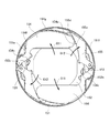
図12は、バリア主羽根とバリア副羽根とで構成される形状を説明する図である。図12に示すように、バリア主羽根154とバリア副羽根155とで構成される形状は、キャップ157の開口部157aの形状と略近似の関係にある。これにより、バリア形状を最小にすると共に、バリア筒151のキャップ貼り付け面151gの面積を可能な限り多くとることが可能となる。また、キャップ貼り付け面151gの面積を多く取れることで、キャップ157の接着強度を増加することができる。
FIG. 12 is a diagram for explaining a shape composed of a barrier main blade and a barrier sub blade. As shown in FIG. 12, the shape constituted by the barrier
以上説明した本実施形態のバリア装置によれば、バリア主羽根、バリア副羽根のそれぞれに対応する閉じバネを不要とすることができ、部品点数の増加を抑えることができる。また、このバリア装置は、本実施例においてはバリア副羽根155は回転付勢されていないので、バネバランスの設定が不要となる。これにより、コストダウンが可能となり、さらに組立性も向上する。また、このバリア装置では、開状態から閉状態への移行時に、バリア主羽根154の当接面154dに当接面155bが押される形で、バリア副羽根155bがバリア閉方向へと回転する。これにより、バリア主羽根とバリア副羽根との間で不必要な摩擦が発生しない。
According to the barrier device of the present embodiment described above, the closing springs corresponding to the barrier main blades and the barrier sub blades can be eliminated, and an increase in the number of parts can be suppressed. Further, in this barrier device, since the
ここで、バリア副羽根155とバリア筒151との嵌合について説明する。図13は、バリア副羽根の断面図の例である。図14は、バリア副羽根の回転軸付近の拡大図である。前述の通り、バリア副羽根155は、回転穴155aを有している。回転穴155aは、バリア筒151が備える回転軸151dと嵌合する。そのため、回転軸151dと回転穴155aとの嵌合長は、バリア羽根155の厚みに相当する嵌合長155gしか確保することができない。その結果、バリア副羽根155をバリア筒151へ組むときは、嵌合長が短いので、バリア副羽根155が非常に外れやすくなってしまう。
Here, the fitting between the
しかし、本実施形態では、図15に示すように、バリア副羽根155は、その回転軸方向(光軸方向)へ伸びた嵌合長155gよりも長い長手部155hを有している。このため、バリア副羽根155をバリア筒151へ組み付ける際、長手部155hの効果で、不用意にはずれることを低減することができる。
However, in this embodiment, as shown in FIG. 15, the
長手部155hは、嵌合軸151dを挟んで、光軸と反対側に配置されている。これにより、鏡筒中心側のスペースを確保することができるため、レンズの広角化に伴い第1レンズ101が大径化した際も、鏡筒の外径サイズを小さくすることが可能となる。
The
また、本構成をとることで、バリア筒151のバリア副羽根155の回転軸径151hよりも嵌合長155gが短い構成のバリア羽根においても、組立性を向上させることが可能となる。
Further, by adopting this configuration, it is possible to improve assemblability even in a barrier blade having a configuration in which the
本発明の好ましい実施形態について説明したが、本発明はこれらの実施形態に限定されず、その要旨の範囲内で種々の変形及び変更が可能である。 Although preferable embodiment of this invention was described, this invention is not limited to these embodiment, A various deformation | transformation and change are possible within the range of the summary.
151 バリア筒
152 バリアドライブリング
153 バリア開きバネ
154 バリア主羽根
155 バリア副羽根
151
Claims (11)
前記第1および第2の遮蔽部材を駆動して、前記閉状態または開状態に遷移させる駆動部材とを備え、
前記第2の遮蔽部材が備える、前記第1の遮蔽部材との第1の当接面の一部が、前記開状態または前記閉状態のいずれの状態において、前記第1の遮蔽部材が備える、前記第2の遮蔽部材との第2の当接面の作動範囲内に位置し、
前記第1の遮蔽部材と前記第2の遮蔽部材は、互いに逆方向に回動する
ことを特徴とするバリア装置。 First and second shielding members that transition between a closed state that shields the lens and an open state that exposes the lens;
A driving member that drives the first and second shielding members to transition to the closed state or the open state;
A part of the first contact surface with the first shielding member provided in the second shielding member is provided in the first shielding member in either the open state or the closed state . Located within the operating range of the second abutment surface with the second shielding member ;
The barrier device, wherein the first shielding member and the second shielding member rotate in opposite directions .
ことを特徴とする請求項1に記載のバリア装置。 The second shielding member rotates when the mating surface with the first shielding member is pushed by the distal end portion of the first shielding member that rotates so as to be in the open state by the driving member. The barrier device according to claim 1, wherein the barrier device transitions from the closed state to the open state.
ことを特徴とする請求項1または請求項2に記載のバリア装置。 The second shielding member is pushed by the second contact surface of the first shielding member that is rotated by the driving member so that the first contact surface is in the closed state. 3. The barrier device according to claim 1, wherein the barrier device rotates and transitions from the open state to the closed state.
ことを特徴とする請求項1乃至3のいずれか1項に記載のバリア装置。 The said 2nd shielding member is in an optical-axis direction photographic subject side from the 2nd contact surface of the said 1st shielding member in any state of the said closed state or the said open state. The barrier device according to any one of 1 to 3 .
前記遮蔽筒は、前記第2の遮蔽部材に設けられた回転穴と嵌合する回転軸を有しており、
前記第2の遮蔽部材は、前記回転軸と前記回転穴との嵌合長より光軸方向に長い長手部を有している
ことを特徴とする請求項1乃至4のいずれか1項に記載のバリア装置。 A shielding cylinder that rotatably holds the first and second shielding members;
The shielding cylinder has a rotation shaft that fits into a rotation hole provided in the second shielding member;
The said 2nd shielding member has a longitudinal part longer in the optical axis direction than the fitting length of the said rotating shaft and the said rotation hole. The any one of Claims 1 thru | or 4 characterized by the above-mentioned. Barrier device.
ことを特徴とする請求項5に記載のバリア装置。 The barrier device according to claim 5 , wherein the longitudinal portion is provided on a side opposite to the optical axis with the rotation shaft interposed therebetween.
ことを特徴とする請求項5または請求項6に記載のバリア装置。 In the closed state, the shape formed by the first shielding member and the second shielding member approximates an opening of a cover member attached to the subject side of the shielding cylinder. The barrier device according to claim 5 or 6 .
前記第1および第2の遮蔽部材を駆動して、前記閉状態または開状態に遷移させる駆動部材とを備え、
前記第2の遮蔽部材が備える、前記第1の遮蔽部材との第1の当接面の一部が、前記開状態または前記閉状態のいずれの状態において、前記第1の遮蔽部材が備える、前記第2の遮蔽部材との第2の当接面の作動範囲内に位置し、
前記閉状態において、前記第1の遮蔽部材の先端部は、前記第2の遮蔽部材の前記第1の当接面より光軸方向被写体側にある
ことを特徴とするバリア装置。 First and second shielding members that transition between a closed state that shields the lens and an open state that exposes the lens;
A driving member that drives the first and second shielding members to transition to the closed state or the open state;
A part of the first contact surface with the first shielding member provided in the second shielding member is provided in the first shielding member in either the open state or the closed state. Located within the operating range of the second abutment surface with the second shielding member;
Wherein in the closed state, the tip portion of the first shielding member, characterized and to Luba rear unit to be in the optical axis direction the object side than the first contact surface of the second shielding member.
前記第1および第2の遮蔽部材を駆動して、前記閉状態または開状態に遷移させる駆動部材とを備え、
前記第2の遮蔽部材が備える、前記第1の遮蔽部材との第1の当接面の一部が、前記開状態または前記閉状態のいずれの状態において、前記第1の遮蔽部材が備える、前記第2の遮蔽部材との第2の当接面の作動範囲内に位置し、
前記閉状態の時に、前記第2の遮蔽部材の先端部に設けられた第3の当接面が、前記第1の遮蔽部材の合わせ面と当接することで、前記開状態を維持する
ことを特徴とするバリア装置。 First and second shielding members that transition between a closed state that shields the lens and an open state that exposes the lens;
A driving member that drives the first and second shielding members to transition to the closed state or the open state;
A part of the first contact surface with the first shielding member provided in the second shielding member is provided in the first shielding member in either the open state or the closed state. Located within the operating range of the second abutment surface with the second shielding member;
When the closed state, the third contact surface provided at the tip of the second shielding member is in contact with the mating surface of the first shielding member to maintain the open state. features and to Luba rear unit.
An imaging device comprising the lens barrel according to claim 10 .
Priority Applications (3)
| Application Number | Priority Date | Filing Date | Title |
|---|---|---|---|
| JP2013012999A JP6116261B2 (en) | 2013-01-28 | 2013-01-28 | Barrier device, lens barrel, and imaging device including the same |
| US14/156,577 US8974129B2 (en) | 2013-01-28 | 2014-01-16 | Barrier device, lens barrel, and imaging apparatus including same |
| CN201410042327.5A CN103969917B (en) | 2013-01-28 | 2014-01-28 | Barrier device, lens barrel, and imaging apparatus including lens barrel |
Applications Claiming Priority (1)
| Application Number | Priority Date | Filing Date | Title |
|---|---|---|---|
| JP2013012999A JP6116261B2 (en) | 2013-01-28 | 2013-01-28 | Barrier device, lens barrel, and imaging device including the same |
Publications (3)
| Publication Number | Publication Date |
|---|---|
| JP2014145820A JP2014145820A (en) | 2014-08-14 |
| JP2014145820A5 JP2014145820A5 (en) | 2016-03-03 |
| JP6116261B2 true JP6116261B2 (en) | 2017-04-19 |
Family
ID=51223059
Family Applications (1)
| Application Number | Title | Priority Date | Filing Date |
|---|---|---|---|
| JP2013012999A Expired - Fee Related JP6116261B2 (en) | 2013-01-28 | 2013-01-28 | Barrier device, lens barrel, and imaging device including the same |
Country Status (3)
| Country | Link |
|---|---|
| US (1) | US8974129B2 (en) |
| JP (1) | JP6116261B2 (en) |
| CN (1) | CN103969917B (en) |
Families Citing this family (5)
| Publication number | Priority date | Publication date | Assignee | Title |
|---|---|---|---|---|
| JP5858902B2 (en) * | 2012-11-26 | 2016-02-10 | キヤノン株式会社 | Lens barrel and imaging device |
| JP6305048B2 (en) | 2013-12-17 | 2018-04-04 | キヤノン株式会社 | Optical equipment |
| JP6460667B2 (en) | 2014-07-16 | 2019-01-30 | キヤノン株式会社 | Optical equipment |
| IL302577A (en) * | 2017-02-23 | 2023-07-01 | Corephotonics Ltd | Folded camera lens designs |
| US11514357B2 (en) * | 2018-03-19 | 2022-11-29 | Kla-Tencor Corporation | Nuisance mining for novel defect discovery |
Family Cites Families (10)
| Publication number | Priority date | Publication date | Assignee | Title |
|---|---|---|---|---|
| JP2006235534A (en) * | 2005-02-28 | 2006-09-07 | Sony Corp | Imaging apparatus |
| US7920336B2 (en) * | 2007-08-03 | 2011-04-05 | Canon Kabushiki Kaisha | Barrier mechanism and camera |
| JP5506169B2 (en) | 2008-08-04 | 2014-05-28 | キヤノン株式会社 | Barrier device and camera equipped with the same |
| JP2010152236A (en) * | 2008-12-26 | 2010-07-08 | Tamron Co Ltd | Barrier mechanism, lens device, and imaging apparatus |
| US8061909B2 (en) * | 2009-01-16 | 2011-11-22 | Canon Kabushiki Kaisha | Barrier device and image pickup apparatus |
| JP5463703B2 (en) * | 2009-03-17 | 2014-04-09 | 株式会社リコー | Barrier mechanism, lens barrel, and imaging device |
| JP5121812B2 (en) * | 2009-12-25 | 2013-01-16 | キヤノン株式会社 | Lens barrier device |
| JP5121811B2 (en) * | 2009-12-25 | 2013-01-16 | キヤノン株式会社 | Lens barrier device and lens barrel including the same |
| JP5762007B2 (en) * | 2011-01-17 | 2015-08-12 | キヤノン株式会社 | Lens barrel and camera having lens barrel |
| JP5882716B2 (en) | 2011-12-16 | 2016-03-09 | キヤノン株式会社 | Lens barrel and imaging device |
-
2013
- 2013-01-28 JP JP2013012999A patent/JP6116261B2/en not_active Expired - Fee Related
-
2014
- 2014-01-16 US US14/156,577 patent/US8974129B2/en not_active Expired - Fee Related
- 2014-01-28 CN CN201410042327.5A patent/CN103969917B/en not_active Expired - Fee Related
Also Published As
| Publication number | Publication date |
|---|---|
| US8974129B2 (en) | 2015-03-10 |
| JP2014145820A (en) | 2014-08-14 |
| CN103969917B (en) | 2017-01-18 |
| US20140212122A1 (en) | 2014-07-31 |
| CN103969917A (en) | 2014-08-06 |
Similar Documents
| Publication | Publication Date | Title |
|---|---|---|
| JP6116261B2 (en) | Barrier device, lens barrel, and imaging device including the same | |
| US8248709B2 (en) | Zoom lens barrel that attains a higher photographing magnification | |
| US9798158B2 (en) | Optical apparatus capable of retracting optical element from optical path | |
| US20200225441A1 (en) | Lens barrel and imaging device | |
| JP2014119500A (en) | Lens barrel | |
| JP5094137B2 (en) | Lens barrier mechanism and optical device | |
| JP5013719B2 (en) | LENS DEVICE AND IMAGING DEVICE | |
| JP2005308810A (en) | Lens barrel and imaging apparatus | |
| JP2014106264A (en) | Lens barrel, and imaging apparatus | |
| JP5463703B2 (en) | Barrier mechanism, lens barrel, and imaging device | |
| JP5448629B2 (en) | Optical unit and optical equipment | |
| JP2008292878A (en) | Lens barrier device | |
| JP6084017B2 (en) | Lens barrel and imaging device | |
| JP4589816B2 (en) | Lens barrel drive mechanism | |
| JP6257342B2 (en) | Optical equipment | |
| JP2011039086A5 (en) | ||
| JP2017120312A (en) | Lens barrel and imaging apparatus | |
| JP6238762B2 (en) | Optical equipment | |
| JP2019200268A (en) | Lens barrier | |
| JP5975862B2 (en) | Viewfinder correction device | |
| JP6022313B2 (en) | Lens barrier mechanism of lens barrel | |
| JP6351270B2 (en) | Optical equipment | |
| JP6061699B2 (en) | Barrier device, lens barrel, and imaging device | |
| JP2011033818A (en) | Barrier unit, lens barrel and camera | |
| JP2019095496A (en) | Imaging device |
Legal Events
| Date | Code | Title | Description |
|---|---|---|---|
| A521 | Request for written amendment filed |
Free format text: JAPANESE INTERMEDIATE CODE: A523 Effective date: 20160119 |
|
| A621 | Written request for application examination |
Free format text: JAPANESE INTERMEDIATE CODE: A621 Effective date: 20160119 |
|
| A977 | Report on retrieval |
Free format text: JAPANESE INTERMEDIATE CODE: A971007 Effective date: 20161104 |
|
| A131 | Notification of reasons for refusal |
Free format text: JAPANESE INTERMEDIATE CODE: A131 Effective date: 20161122 |
|
| A521 | Request for written amendment filed |
Free format text: JAPANESE INTERMEDIATE CODE: A523 Effective date: 20170123 |
|
| TRDD | Decision of grant or rejection written | ||
| A01 | Written decision to grant a patent or to grant a registration (utility model) |
Free format text: JAPANESE INTERMEDIATE CODE: A01 Effective date: 20170221 |
|
| A61 | First payment of annual fees (during grant procedure) |
Free format text: JAPANESE INTERMEDIATE CODE: A61 Effective date: 20170321 |
|
| R151 | Written notification of patent or utility model registration |
Ref document number: 6116261 Country of ref document: JP Free format text: JAPANESE INTERMEDIATE CODE: R151 |
|
| LAPS | Cancellation because of no payment of annual fees |