JP6113293B2 - Robot for walking rehabilitation of stroke patients - Google Patents
Robot for walking rehabilitation of stroke patients Download PDFInfo
- Publication number
- JP6113293B2 JP6113293B2 JP2015538007A JP2015538007A JP6113293B2 JP 6113293 B2 JP6113293 B2 JP 6113293B2 JP 2015538007 A JP2015538007 A JP 2015538007A JP 2015538007 A JP2015538007 A JP 2015538007A JP 6113293 B2 JP6113293 B2 JP 6113293B2
- Authority
- JP
- Japan
- Prior art keywords
- patient
- robot
- rehabilitation
- arm
- joint axis
- Prior art date
- Legal status (The legal status is an assumption and is not a legal conclusion. Google has not performed a legal analysis and makes no representation as to the accuracy of the status listed.)
- Active
Links
- 208000006011 Stroke Diseases 0.000 title claims description 15
- 210000002683 foot Anatomy 0.000 claims description 9
- 210000000544 articulatio talocruralis Anatomy 0.000 claims description 8
- 230000005021 gait Effects 0.000 claims description 4
- 210000001624 hip Anatomy 0.000 description 11
- 230000037237 body shape Effects 0.000 description 3
- 210000003127 knee Anatomy 0.000 description 3
- 210000000629 knee joint Anatomy 0.000 description 3
- 210000002414 leg Anatomy 0.000 description 3
- 210000003205 muscle Anatomy 0.000 description 3
- 208000034819 Mobility Limitation Diseases 0.000 description 2
- 210000003423 ankle Anatomy 0.000 description 2
- 238000012937 correction Methods 0.000 description 2
- 238000010586 diagram Methods 0.000 description 2
- 210000004197 pelvis Anatomy 0.000 description 2
- 208000035657 Abasia Diseases 0.000 description 1
- 206010039203 Road traffic accident Diseases 0.000 description 1
- 206010003246 arthritis Diseases 0.000 description 1
- 238000005452 bending Methods 0.000 description 1
- 230000035876 healing Effects 0.000 description 1
- 210000004394 hip joint Anatomy 0.000 description 1
- 238000004519 manufacturing process Methods 0.000 description 1
- 238000000034 method Methods 0.000 description 1
- 210000005036 nerve Anatomy 0.000 description 1
- 210000001032 spinal nerve Anatomy 0.000 description 1
- 238000005728 strengthening Methods 0.000 description 1
Images


Classifications
-
- A—HUMAN NECESSITIES
- A61—MEDICAL OR VETERINARY SCIENCE; HYGIENE
- A61H—PHYSICAL THERAPY APPARATUS, e.g. DEVICES FOR LOCATING OR STIMULATING REFLEX POINTS IN THE BODY; ARTIFICIAL RESPIRATION; MASSAGE; BATHING DEVICES FOR SPECIAL THERAPEUTIC OR HYGIENIC PURPOSES OR SPECIFIC PARTS OF THE BODY
- A61H3/00—Appliances for aiding patients or disabled persons to walk about
- A61H3/04—Wheeled walking aids for disabled persons
-
- A—HUMAN NECESSITIES
- A61—MEDICAL OR VETERINARY SCIENCE; HYGIENE
- A61H—PHYSICAL THERAPY APPARATUS, e.g. DEVICES FOR LOCATING OR STIMULATING REFLEX POINTS IN THE BODY; ARTIFICIAL RESPIRATION; MASSAGE; BATHING DEVICES FOR SPECIAL THERAPEUTIC OR HYGIENIC PURPOSES OR SPECIFIC PARTS OF THE BODY
- A61H1/00—Apparatus for passive exercising; Vibrating apparatus ; Chiropractic devices, e.g. body impacting devices, external devices for briefly extending or aligning unbroken bones
- A61H1/02—Stretching or bending or torsioning apparatus for exercising
- A61H1/0237—Stretching or bending or torsioning apparatus for exercising for the lower limbs
- A61H1/0244—Hip
-
- A—HUMAN NECESSITIES
- A61—MEDICAL OR VETERINARY SCIENCE; HYGIENE
- A61H—PHYSICAL THERAPY APPARATUS, e.g. DEVICES FOR LOCATING OR STIMULATING REFLEX POINTS IN THE BODY; ARTIFICIAL RESPIRATION; MASSAGE; BATHING DEVICES FOR SPECIAL THERAPEUTIC OR HYGIENIC PURPOSES OR SPECIFIC PARTS OF THE BODY
- A61H1/00—Apparatus for passive exercising; Vibrating apparatus ; Chiropractic devices, e.g. body impacting devices, external devices for briefly extending or aligning unbroken bones
- A61H1/02—Stretching or bending or torsioning apparatus for exercising
- A61H1/0237—Stretching or bending or torsioning apparatus for exercising for the lower limbs
- A61H1/0266—Foot
-
- A—HUMAN NECESSITIES
- A61—MEDICAL OR VETERINARY SCIENCE; HYGIENE
- A61H—PHYSICAL THERAPY APPARATUS, e.g. DEVICES FOR LOCATING OR STIMULATING REFLEX POINTS IN THE BODY; ARTIFICIAL RESPIRATION; MASSAGE; BATHING DEVICES FOR SPECIAL THERAPEUTIC OR HYGIENIC PURPOSES OR SPECIFIC PARTS OF THE BODY
- A61H3/00—Appliances for aiding patients or disabled persons to walk about
-
- B—PERFORMING OPERATIONS; TRANSPORTING
- B25—HAND TOOLS; PORTABLE POWER-DRIVEN TOOLS; MANIPULATORS
- B25J—MANIPULATORS; CHAMBERS PROVIDED WITH MANIPULATION DEVICES
- B25J5/00—Manipulators mounted on wheels or on carriages
-
- A—HUMAN NECESSITIES
- A61—MEDICAL OR VETERINARY SCIENCE; HYGIENE
- A61H—PHYSICAL THERAPY APPARATUS, e.g. DEVICES FOR LOCATING OR STIMULATING REFLEX POINTS IN THE BODY; ARTIFICIAL RESPIRATION; MASSAGE; BATHING DEVICES FOR SPECIAL THERAPEUTIC OR HYGIENIC PURPOSES OR SPECIFIC PARTS OF THE BODY
- A61H2201/00—Characteristics of apparatus not provided for in the preceding codes
- A61H2201/16—Physical interface with patient
- A61H2201/1602—Physical interface with patient kind of interface, e.g. head rest, knee support or lumbar support
- A61H2201/1628—Pelvis
- A61H2201/163—Pelvis holding means therefor
-
- A—HUMAN NECESSITIES
- A61—MEDICAL OR VETERINARY SCIENCE; HYGIENE
- A61H—PHYSICAL THERAPY APPARATUS, e.g. DEVICES FOR LOCATING OR STIMULATING REFLEX POINTS IN THE BODY; ARTIFICIAL RESPIRATION; MASSAGE; BATHING DEVICES FOR SPECIAL THERAPEUTIC OR HYGIENIC PURPOSES OR SPECIFIC PARTS OF THE BODY
- A61H2201/00—Characteristics of apparatus not provided for in the preceding codes
- A61H2201/16—Physical interface with patient
- A61H2201/1602—Physical interface with patient kind of interface, e.g. head rest, knee support or lumbar support
- A61H2201/1635—Hand or arm, e.g. handle
-
- A—HUMAN NECESSITIES
- A61—MEDICAL OR VETERINARY SCIENCE; HYGIENE
- A61H—PHYSICAL THERAPY APPARATUS, e.g. DEVICES FOR LOCATING OR STIMULATING REFLEX POINTS IN THE BODY; ARTIFICIAL RESPIRATION; MASSAGE; BATHING DEVICES FOR SPECIAL THERAPEUTIC OR HYGIENIC PURPOSES OR SPECIFIC PARTS OF THE BODY
- A61H2201/00—Characteristics of apparatus not provided for in the preceding codes
- A61H2201/16—Physical interface with patient
- A61H2201/1602—Physical interface with patient kind of interface, e.g. head rest, knee support or lumbar support
- A61H2201/164—Feet or leg, e.g. pedal
-
- A—HUMAN NECESSITIES
- A61—MEDICAL OR VETERINARY SCIENCE; HYGIENE
- A61H—PHYSICAL THERAPY APPARATUS, e.g. DEVICES FOR LOCATING OR STIMULATING REFLEX POINTS IN THE BODY; ARTIFICIAL RESPIRATION; MASSAGE; BATHING DEVICES FOR SPECIAL THERAPEUTIC OR HYGIENIC PURPOSES OR SPECIFIC PARTS OF THE BODY
- A61H2201/00—Characteristics of apparatus not provided for in the preceding codes
- A61H2201/16—Physical interface with patient
- A61H2201/1602—Physical interface with patient kind of interface, e.g. head rest, knee support or lumbar support
- A61H2201/165—Wearable interfaces
-
- A—HUMAN NECESSITIES
- A61—MEDICAL OR VETERINARY SCIENCE; HYGIENE
- A61H—PHYSICAL THERAPY APPARATUS, e.g. DEVICES FOR LOCATING OR STIMULATING REFLEX POINTS IN THE BODY; ARTIFICIAL RESPIRATION; MASSAGE; BATHING DEVICES FOR SPECIAL THERAPEUTIC OR HYGIENIC PURPOSES OR SPECIFIC PARTS OF THE BODY
- A61H2205/00—Devices for specific parts of the body
- A61H2205/10—Leg
Description
本発明は、脳卒中患者の歩行リハビリテーション用ロボットに関するものであり、より詳細には、患者の身体や体型に関係なく、不特定の患者が容易に動作させることができ、また素早く装着することもでき、リハビリテーションにかかる時間とコストが軽減できる脳卒中患者の歩行リハビリテーション用ロボットに関するものである。 The present invention relates to a robot for walking rehabilitation of a stroke patient, and more specifically, it can be easily operated by an unspecified patient regardless of the patient's body and body shape, and can be quickly worn. The present invention relates to a walking rehabilitation robot for stroke patients that can reduce the time and cost of rehabilitation.
脳卒中や交通事故などで脊髄神経が損傷を受けて歩行困難になった人がよく見られ、関節炎もある場合にはちゃんと立っていることも困難な場合がほとんどである。特に、老人や長期間病床にあった人は、足の筋力が衰え、股関節や膝関節を動かして歩行することは大きな苦痛であった。 People with spinal nerves damaged due to stroke or traffic accidents often have difficulty walking, and when there is arthritis, it is often difficult to stand properly. In particular, elderly people and those who have been on the bed for a long time had weak muscles in their legs, and it was a great pain to walk with their hip and knee joints moving.
このように歩行が困難な人の場合、無理やり歩かせることで、足の筋力を増強させながら下半身の神経が蘇生し、治癒の効果がもたらすこができる。 In the case of such a person who is difficult to walk, by forcibly walking, the nerve of the lower body is revived while strengthening the muscle strength of the foot, and a healing effect can be brought about.
これらを背景に最近、歩行器がリハビリテーションの手段として多く活用されている。 Against this background, recently, walker has been widely used as a means of rehabilitation.
前記歩行器は、歩行困難な人が立っている状態で、手で掴んで体を寄せることができるフレームの下方に車輪を装着したものであり、使用者は体を歩行器に頼った状態で押して少しずつ進むことになる。 The walker is equipped with a wheel below the frame where a person who has difficulty walking can stand and grabs by hand, and the user relies on the walker for the body. Push and move forward little by little.
この他にも、歩行が不自由な患者や老人の場合、ベッドに横になった状態で理学療法士が直接足を引いたり伸ばしたりする動作を繰り返して治療を行う。 In addition to this, in the case of patients and elderly people who are unable to walk, the physical therapist performs treatment by repeatedly pulling and stretching their legs while lying on the bed.
まず、歩行器の場合、患者が直接歩行器のハンドルを握って歩行するので、体が不自由な患者が歩行動作においてより大きいストレスを受けるとともに、余計に体力の消耗が激しいなどの問題点があった。 First of all, in the case of a walker, since the patient walks by directly holding the handle of the walker, there is a problem that a physically handicapped patient is subjected to greater stress during walking and excessive exhaustion of physical strength. there were.
また、リハビリテーション療法士が患者の足をマッサージする場合にも、患者が自らリハビリテーション運動をするのではないので、リハビリテーションの効率性が落ちる問題点があり、リハビリテーションの際、いつも一人以上の療法士がとなりに待機していなければならず、リハビリテーション患者の治療費の負担がそれほど大きくならざるをえないという問題点がある。 In addition, when a rehabilitation therapist massages a patient's foot, the patient does not rehabilitate themselves, so there is a problem that the efficiency of the rehabilitation is reduced. At the time of rehabilitation, one or more therapists are always present. There is a problem that the patient must be waiting next to the patient, and the burden of treatment for rehabilitation patients must be so large.
これらの問題点を補完するための手段として、患者の下半身に自律運動するロボットを装着して、リハビリテーション患者がロボットの動作に応じて自然に足を動かす方法が開発されたが、たいていのリハビリテーションロボットは、患者の下半身の腰、骨盤、膝および足首を結束した状態でリハビリテーションを進めるので、リハビリテーションロボットの動作時間が長すぎる問題があり、また、リハビリテーション対象の患者の身体的特定(体型)にぴったりと合うように設計しなければならないので、リハビリテーションロボットの設計及び製作単価が高くなり、多くの患者に提供できない問題があった。 As a means to compensate for these problems, a method has been developed in which a robot that moves autonomously on the lower body of the patient and the rehabilitation patient moves their feet naturally according to the movement of the robot, but most rehabilitation robots Since the rehabilitation proceeds with the patient's lower body waist, pelvis, knees and ankles tied together, there is a problem that the rehabilitation robot is operating too long, and it is perfect for the physical identification (body type) of the patient to be rehabilitated. Therefore, the design and production unit cost of the rehabilitation robot is high, and there is a problem that cannot be provided to many patients.
本発明の目的は、上記のような従来の特性を改善するために提案されたものであって、患者の身体や体型に関係なく、不特定の患者が容易に動作させることができ、また素早く装着することもでき、リハビリテーションにかかる時間とコストが軽減できる脳卒中患者の歩行リハビリテーション用ロボットを提供することにある。 An object of the present invention is proposed to improve the conventional characteristics as described above, and can be easily operated by an unspecified patient regardless of the patient's body or body shape. An object of the present invention is to provide a robot for walking rehabilitation of a stroke patient that can be worn and can reduce the time and cost of rehabilitation.
上記目的を達成するために、本発明は次のように構成される。 In order to achieve the above object, the present invention is configured as follows.
本発明による脳卒中患者の歩行リハビリテーションテーション用ロボットは、患者の胴部を支持する固定バンドと、前記固定バンドと回転可能に連結された骨盤関節軸と、前記骨盤関節軸から下側に一定の長さで延びる第1アームと、前記第1アームと連結された第1連結関節軸と、前記第1連結関節軸から下側に延びる第2アームと、前記第2アームに回転可能に連結された第2連結関節軸と、前記第2連結関節軸から下側に延びる延長片と、前記延長片から足首関節軸によって回転可能に連結されて、患者の足を固定して支持するフットレストとを備えるロボット本体と、前記ロボット本体の固定バンド側を支持する上部フレームと、前記上部フレームを支持する連結フレームと、前記連結フレームと連結され、複数の車輪が設けられた下部フレームとを備える歩行器とを含み、前記第1アームと第2アームの角度は患者の下半身の長さに応じて調節される。 A robot for walking rehabilitation of a stroke patient according to the present invention includes a fixed band that supports a torso of a patient, a pelvic joint axis that is rotatably connected to the fixed band, and a constant length downward from the pelvic joint axis. A first connecting joint shaft connected to the first arm, a second arm extending downward from the first connecting joint shaft, and a second arm rotatably connected to the second arm. A second connection joint shaft; an extension piece extending downward from the second connection joint axis; and a footrest fixedly supported by the ankle joint shaft for fixing and supporting a patient's foot from the extension piece. A robot body, an upper frame that supports a fixed band side of the robot body, a connection frame that supports the upper frame, and a plurality of wheels that are connected to the connection frame. And a walker and a section frame, the angle of the first arm and the second arm is adjusted according to the length of the lower body of the patient.
そして、前記フットレストは、前記第1アームと第2アームの角度の変化に関係なく、常時地面に対して垂直状態を維持する。 And the said footrest always maintains a perpendicular | vertical state with respect to the ground irrespective of the change of the angle of the said 1st arm and a 2nd arm.
また、前記固定バンドは、腰を支持する腰支持部をさらに備える。 The fixing band further includes a waist support portion that supports the waist.
そして、前記腰支持部は、幅方向の長さを調節する間隔調節部を備える。 And the said waist support part is provided with the space | interval adjustment part which adjusts the length of the width direction.
また、前記固定バンドと前記上部フレームとの間には、相互連結状態を維持してリハビリテーション患者が歩行器の外部に離脱することを防止する安全手段がさらに備えられる。 Further, a safety means is further provided between the fixed band and the upper frame to prevent the rehabilitation patient from leaving the walker by maintaining an interconnected state.
そして、前記安全手段は、ワイヤまたはフレキシブルケーブルのいずれか一つである。 The safety means is one of a wire and a flexible cable.
本発明によれば、患者の身体や体型に関係なく、不特定の患者が容易に動作させることができ、また素早く装着することもでき、リハビリテーションにかかる時間とコストが軽減できる。 According to the present invention, an unspecified patient can be easily operated regardless of the patient's body and body shape, and can be quickly worn, and the time and cost for rehabilitation can be reduced.
以下、本発明の好ましい実施例について添付図面を参照して詳細に説明する。本発明の実施例は、様々な形態で実施することができ、本明細書で説明する実施例に限定されるものと解釈してはならない。本発明の実施例は、当該発明が属する技術分野における通常の知識を有する者に本発明をより詳細に説明するために提供されるものであり、図面に示された各要素の形状は、説明を明確にするため誇張していることがある。 Hereinafter, preferred embodiments of the present invention will be described in detail with reference to the accompanying drawings. Embodiments of the present invention can be implemented in various forms and should not be construed as limited to the embodiments set forth herein. The embodiments of the present invention are provided to explain the present invention in more detail to those skilled in the art to which the present invention pertains, and the shape of each element shown in the drawings is described below. May be exaggerated to clarify.
第1及び/又は第2等の用語は多様な構成要素を説明するのに使用されるが、上記構成要素は上記用語に限定されない。上記用語は、一つの構成要素を他の構成要素から区別する目的でのみ使用される。 Although terms such as first and / or second are used to describe various components, the components are not limited to the terms. The above terms are only used to distinguish one component from another.
本明細書で使用した用語は、単に特定の実施例を説明するために使用されたものであって、本発明を限定しようとする意図ではない。単数の表現は文脈上明らかに異なるものを意味しない限り、複数の表現を含む。本明細書において、「備える(含む)」又は「有する」等の用語は、説示された特徴、数字、段階、動作、構成要素、部分品、又はそれらを組み合わせたものが存在することを指定しようとするものであり、1つ若しくはそれ以上の他の特徴や数字、段階、動作、構成要素、部分品、又はそれらを組み合わせたものの存在、又は付加の可能性を予め排除するものではないと理解されるべきである。 The terminology used herein is for the purpose of describing particular embodiments only and is not intended to be limiting of the invention. The singular form includes the plural form unless the context clearly indicates otherwise. In this specification, terms such as “comprising” (including) or “having” will specify that the described feature, number, step, action, component, part, or combination thereof exists. It is understood that the existence of one or more other features or numbers, steps, operations, components, parts, or combinations thereof, or combinations thereof, is not excluded in advance. It should be.
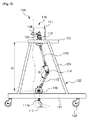
図1〜図3に示すように、本発明による脳卒中患者の歩行リハビリテーションテーション用ロボット100は、患者の胴部を支持する固定バンド111と、前記固定バンド111に回転可能に連結された骨盤関節軸112と、前記骨盤関節軸112から下側に一定の長さで延びる第1アーム113と、前記第1アーム113に連結された第1連結関節軸114と、前記第1連結関節軸114から下側に延びる第2アーム115と、前記第2アーム115に回転可能に連結された第2連結関節軸116と、前記第2連結関節軸116から下側に延びる延長片116aと、前記延長片116aから足首関節軸117aにより回転可能に連結されて、患者の足を固定して支持するフットレスト117とを備えるロボット本体110と、前記ロボット本体110の固定バンド111側を支持する上部フレーム123と、前記上部フレーム123を支持する連結フレーム124と、前記連結フレーム124と連結され、複数の車輪が設けられた下部フレーム121とを備える歩行器120とを含み、前記第1アーム113と第2アーム115の角度は、患者の下半身の長さに応じて調節される。
As shown in FIGS. 1 to 3, a
一方、前記骨盤関節軸112と第2連結関節軸116の内には、電子ねじりばねロック手段(図示せず)が備えられ、前記第1連結関節軸114と足首関節軸117aは、自由回転される構造をしており、前記電子ねじりばねロック手段は、歩行中足が地面に引きずられるのを防止して、自然な歩行のために膝関節の屈曲及び伸展を補助するようになっている。
Meanwhile, an electronic torsion spring locking means (not shown) is provided in the
前記ロック手段は、立脚期にはブレーキでロックされて身体を堅固に支持でき、遊脚期には屈曲できるようにロックが解除され、健常者と同様な歩行時の膝角度を保つようにするとともに、膝の屈曲及び伸展力を得るために、電気刺激装置を用いて膝関節の駆動筋肉を刺激し、歩行を補助する。 The locking means is locked by a brake in the stance period and can firmly support the body, and is unlocked so that it can be bent in the swing period, so that the knee angle during walking can be maintained similar to that of a healthy person. At the same time, in order to obtain knee flexion and extension force, the driving muscles of the knee joint are stimulated using an electric stimulator to assist walking.
また、前記ロボット本体110の固定バンド111と前記上部フレーム123とを安全手段125で連結し、前記安全手段125は、ワイヤやフレキシブルケーブルを用いてもよい。これにより、リハビリ患者が固定バンドによって結束された状態でロボット本体に搭乗し、歩行器との間で安全手段の長さだけ自由に移動する最中にリハビリ患者が倒れる場合、安全手段によって歩行器に支えられて倒れを防止することができる。
Further, the
そして、前記フットレスト117は、前記第1アーム113と第2アーム115の角度変化に関係なく、常に地面に対して垂直状態を維持することが好ましい。これは、前記第1アームと第2アームがリハビリ患者の身長に合わせて夾角(θ)を変更すると、変更された角度によって高さ(H)が調整されるが、この時の調節された角度の変化に応じてフットレストの位置が自然に変更されるようにするためである。
It is preferable that the
また、前記固定バンド111は、一定の弾性を有するベルト型であり、前記固定バンド111の後端にはリハビリ患者の腰を支持することができる腰支持部118が備えられ、前記腰支持部118の中央部分は幅方向の長さを調節できるように間隔調節部119が備えられる。
In addition, the
前記間隔調節部119は、前記腰支持部118よりも直径が大きい管形状を用いて、前記腰支持部が間隔調節部の内部に挿脱して間隔を調節できるようにする。
The
前記足首関節軸117aは、前記第1アーム113と第2アーム115がリハビリ患者の身長に合わせて角度を調節すると、変換された角度だけ自重によって反対方向に回転して地面と垂直状態を維持することであり、前記第2連結関節軸116の動作に応じて回転する場合にも同様の方法で自重によって垂直状態を維持することになる。
When the angle of the
また、前記足首関節軸117aには、図示していないが、前、後の回転方向に一定の弾性を付与できるようにスプリングが設けられてもよい。
Further, although not shown in the drawing, the
一方、図2に示すように、連結フレーム124の他側に設けられるフレームは、リハビリ患者の体重を考慮してさらに設けられてもよい。
On the other hand, as shown in FIG. 2, the frame provided on the other side of the connecting
以下、添付図面を参照して、本発明の動作を説明する。 The operation of the present invention will be described below with reference to the accompanying drawings.
図4及び図5に示すように、まず固定バンド111を取外し、リハビリ患者の腰を固定バンドで包んでリハビリ患者の腰を完全に固定した後、腰支持部118の幅の間隔を調節してリハビリ患者の腰が支持されるようにする。
As shown in FIGS. 4 and 5, first, the
この状態でリハビリ患者の足をフットレスト117に安着した後、前記フットレスト117と共にリハビリ患者の足をバンド(図示せず)で完全に固定する。
In this state, after the foot of the rehabilitation patient is seated on the
この時、リハビリ患者の身長に合わせて第1アーム113と第2アーム115との夾角が自然に調節され、リハビリ患者の下半身(骨盤から足首までの間隔)に適した角度を形成することになる。
At this time, the depression angle between the
この後、リハビリ患者が搭乗した状態でフットレストと共に足で地面を踏み切る動作を行うと、調整された夾角(θ1)内でリハビリ患者の足の曲げ角度に応じて第1アームと第2アームとの夾角が狭くなり、リハビリ治療ができるようになり、同様に骨盤関節軸と第2連結関節軸もリハビリ患者の動作に合わせて共に動作することになる。 Thereafter, when the rehabilitation patient is on the ground with the footrest while stepping on the ground, the first arm and the second arm are moved in accordance with the bending angle of the rehabilitation patient's foot within the adjusted depression angle (θ1). The depression angle becomes narrower and rehabilitation treatment becomes possible. Similarly, the pelvic joint axis and the second connection joint axis move together in accordance with the movement of the rehabilitation patient.
この時、前記骨盤関節軸と第2連結関節軸は、制御部の制御信号に基づいてモータ駆動され、前記第1連結関節軸と足首関節軸は軸のみで連結されており、リハビリ患者の動作に応じて自然に回転することができる。 At this time, the pelvic joint axis and the second connection joint axis are motor-driven based on the control signal of the control unit, and the first connection joint axis and the ankle joint axis are connected only by the axis, and the operation of the rehabilitation patient Depending on the, it can rotate naturally.
本実施例では、ロボット本体の動作制御に関する構成を記載していないが、別の制御部を用いて骨盤関節軸112、第2連結関節軸116を動作させることができ、これらの動作により、リハビリ患者の下半身を自然に運動させて治療し、前記骨盤関節軸112、第2連結関節軸116は、従来のリハビリロボットのものと同様の構成を備えるので具体的な説明を省略する。
In this embodiment, the configuration relating to the operation control of the robot body is not described, but the pelvic
また、前記骨盤関節軸112から第2連結関節軸116までの最初の高さ(H)は、リハビリ患者の下半身の長さに応じて、第1アーム113と第2アーム115の角度によって高さ(H1)に調節できるのは前述した通りである。
The initial height (H) from the pelvic
すなわち、前記第1アーム113と第2アーム115との夾角(θ)が、リハビリ患者が搭乗してリハビリ患者の身長に合わせ調整されると、第2連結関節軸116内で調整された夾角(θ1)以内で動作して、それ以上広がらないように調節する。
That is, when the depression angle (θ) between the
後で他のリハビリ患者が利用する場合には、制御部を介してロック手段によって調整された状態の角度を初期化させて再利用することができる。 When another rehabilitation patient uses it later, the angle adjusted by the lock means can be initialized and reused through the control unit.
また、本発明では、制御部の具体的な説明を省略したが、前記制御部内にリハビリ患者の身長の情報を予め保存して、複数のリハビリ患者に応じて迅速に高さを調節することもできる。 In the present invention, the specific description of the control unit is omitted, but the height information of the rehabilitation patient is stored in the control unit in advance, and the height can be quickly adjusted according to a plurality of rehabilitation patients. it can.
以上、本発明の好適な実施例について説明したが、これは本発明の技術的内容の理解を助けるための一例であり、本発明の技術的範囲はこれに限定されない。 The preferred embodiment of the present invention has been described above, but this is an example for helping understanding of the technical contents of the present invention, and the technical scope of the present invention is not limited thereto.
すなわち、本発明の趣旨及び技術的思想を逸脱しない範囲内において、当該発明の属する技術の分野における通常の知識を有する者であれば、様々な変更や修正、組み合わせ等を行うことに想到できることは明らかである。従って、これらの変更や修正、組み合わせ等も、当然に技術的思想の範囲に属するものである。 In other words, within the scope not departing from the spirit and technical idea of the present invention, those who have ordinary knowledge in the technical field to which the present invention belongs can conceivably make various changes, corrections, combinations, etc. it is obvious. Accordingly, these changes, corrections, combinations, and the like naturally belong to the scope of the technical idea.
Claims (3)
前記ロボット本体の固定バンド側を支持する上部フレームと、前記上部フレームを支持する連結フレームと、前記連結フレームと連結されて複数の車輪が設けられた下部フレームとを備える歩行器とを含み、
前記骨盤関節軸と第2連結関節軸は、モータ駆動される関節で構成され、前記第1連結関節軸と足首関節軸は、自由回転される関節で構成され、
前記骨盤関節軸から第2連結関節軸までの高さは、患者の下半身の長さに応じて、第1アームと第2アームとの夾角により調整されることを特徴とする、脳卒中患者の歩行リハビリ用ロボット。 A fixed band that supports a torso of a patient; a pelvic joint axis that is rotatably connected to the fixed band; a first arm that extends downward from the pelvic joint axis by a certain length; and the first arm; A connected first connecting joint shaft; a second arm extending downward from the first connecting joint shaft; a second connecting joint shaft rotatably connected to the second arm; and the second connecting joint shaft. A robot main body comprising: an extension piece extending downward from the robot; and a footrest that is rotatably connected to the extension piece by an ankle joint shaft and supports a patient's foot.
An upper frame supporting the fixed band side of the robot body, a connecting frame for supporting the upper frame, viewed contains a walker said is connected to the connection frame and a lower frame having a plurality of wheels are provided,
The pelvic joint axis and the second connection joint axis are configured by a motor-driven joint , and the first connection joint axis and the ankle joint axis are configured by a freely rotating joint,
The height of the pelvic joint axis to the second connecting joint axis is adjusted by the depression angle between the first arm and the second arm according to the length of the lower body of the patient, and the gait of the stroke patient Rehabilitation robot.
Applications Claiming Priority (3)
| Application Number | Priority Date | Filing Date | Title |
|---|---|---|---|
| KR1020120117259A KR101325066B1 (en) | 2012-10-22 | 2012-10-22 | Gait rehabilitation robot for the stroke |
| KR10-2012-0117259 | 2012-10-22 | ||
| PCT/KR2013/007071 WO2014065493A1 (en) | 2012-10-22 | 2013-08-06 | Robot for walking rehabilitation therapy of stroke patient |
Publications (2)
| Publication Number | Publication Date |
|---|---|
| JP2015532175A JP2015532175A (en) | 2015-11-09 |
| JP6113293B2 true JP6113293B2 (en) | 2017-04-12 |
Family
ID=49856676
Family Applications (1)
| Application Number | Title | Priority Date | Filing Date |
|---|---|---|---|
| JP2015538007A Active JP6113293B2 (en) | 2012-10-22 | 2013-08-06 | Robot for walking rehabilitation of stroke patients |
Country Status (4)
| Country | Link |
|---|---|
| US (1) | US20150238382A1 (en) |
| JP (1) | JP6113293B2 (en) |
| KR (1) | KR101325066B1 (en) |
| WO (1) | WO2014065493A1 (en) |
Families Citing this family (15)
| Publication number | Priority date | Publication date | Assignee | Title |
|---|---|---|---|---|
| ES2877666T3 (en) * | 2014-03-31 | 2021-11-17 | Parker Hannifin Corp | Portable robotic device |
| EP3133998B1 (en) | 2014-04-21 | 2019-07-03 | The Trustees of Columbia University in the City of New York | Human movement research, therapeutic, and diagnostic devices, methods, and systems |
| CN103989570B (en) * | 2014-04-30 | 2017-12-08 | 中国康复研究中心 | A kind of outer power-actuated interactive walking aided ectoskeleton |
| KR101694848B1 (en) * | 2015-06-18 | 2017-01-13 | 주식회사 티이에스 | Gait rehabilitation robot to assist rehabilitation of patient |
| CN105640743B (en) * | 2015-12-17 | 2017-07-25 | 吉林大学 | Multi-functional gait rectifys appearance and walking Reduction of Students' Study Load device |
| CN105456004B (en) * | 2015-12-28 | 2019-02-01 | 中国科学院自动化研究所 | Exoskeleton-type moves walking rehabilitation training device and method |
| PL3509558T3 (en) * | 2016-09-08 | 2023-07-03 | Trexo Robotics Inc. | Mobile weight-bearing powered orthosis device |
| US10639510B2 (en) | 2017-03-20 | 2020-05-05 | The Trustees Of Columbia University In The City Of New York | Human musculoskeletal support and training system methods and devices |
| CN110882133B (en) * | 2018-09-07 | 2022-06-17 | 北京大艾机器人科技有限公司 | Balance assisting device and method for exoskeleton robot |
| CN110946742B (en) * | 2019-12-02 | 2021-11-19 | 南京伟思医疗科技股份有限公司 | Device and method for assisting lower limb robot to transfer gravity center by aid of weight reduction vehicle |
| CN110960403B (en) * | 2019-12-31 | 2021-08-24 | 布法罗机器人科技(成都)有限公司 | Walking safety support and exoskeleton robot |
| CN112587385A (en) * | 2021-01-05 | 2021-04-02 | 石家庄熙美科技有限公司 | Special equipment for leg recovery walking |
| CN113558944A (en) * | 2021-07-12 | 2021-10-29 | 葛忠芬 | Patient auxiliary walking equipment for rehabilitation department |
| CN114029932A (en) * | 2021-11-21 | 2022-02-11 | 北京华能新锐控制技术有限公司 | Support mechanism of flexible arm of warehouse cleaning robot |
| CN114053106A (en) * | 2021-12-09 | 2022-02-18 | 袁靖 | Limb and arm inflation rehabilitation robot |
Family Cites Families (17)
| Publication number | Priority date | Publication date | Assignee | Title |
|---|---|---|---|---|
| US2210269A (en) * | 1938-02-01 | 1940-08-06 | Byron M Taylor | Means to aid in regaining normal body locomotion |
| US5526893A (en) * | 1994-01-27 | 1996-06-18 | H. Eugene Mack | Physical therapy apparatus |
| JP2000233002A (en) * | 1999-02-16 | 2000-08-29 | Murata Mach Ltd | Caster walker |
| KR100716597B1 (en) | 2005-12-30 | 2007-05-09 | 서강대학교산학협력단 | Robot for assistant exoskeletal power |
| ITMI20060187A1 (en) * | 2006-02-03 | 2007-08-04 | Benito Ferrati | ORTHOPEDIC APPARATUS FOR WALKING AND REHABILITATION OF MOTU-LESE PEOPLE |
| CN101460118B (en) * | 2006-06-29 | 2011-12-28 | 本田技研工业株式会社 | Walk assistance device |
| US7938756B2 (en) * | 2007-02-10 | 2011-05-10 | Roy Rodetsky | Powered mobile lifting, gait training and omnidirectional rolling apparatus and method |
| NO326332B1 (en) * | 2007-02-19 | 2008-11-10 | Inspiro As | Exercise equipment for the disabled |
| WO2008124025A1 (en) * | 2007-04-06 | 2008-10-16 | University Of Delaware | Powered orthosis |
| US20100270771A1 (en) * | 2007-10-02 | 2010-10-28 | Tokyo University Of Science Educational Foundation Adminstrative Organization | Walking auxiliary equipment |
| JP5075777B2 (en) * | 2008-09-23 | 2012-11-21 | 本田技研工業株式会社 | Rehabilitation equipment |
| JP2011092507A (en) * | 2009-10-30 | 2011-05-12 | Satsuma Tsushin Kogyo Kk | Body-worn muscular strength assisting device |
| KR101099521B1 (en) * | 2009-12-24 | 2011-12-27 | 한국산재의료원 | Wearable walking assistance robot suit |
| KR20110083143A (en) * | 2010-01-13 | 2011-07-20 | 한국생산기술연구원 | Wearable robot |
| JP4806094B1 (en) | 2010-10-10 | 2011-11-02 | 栄作 斉藤 | Walker |
| GB2484463A (en) * | 2010-10-11 | 2012-04-18 | Jonathan Butters | Apparatus to assist the rehabilitation of disabled persons |
| JP5844054B2 (en) * | 2011-02-25 | 2016-01-13 | 川崎重工業株式会社 | Wearable motion support device |
-
2012
- 2012-10-22 KR KR1020120117259A patent/KR101325066B1/en active IP Right Grant
-
2013
- 2013-08-06 US US14/437,780 patent/US20150238382A1/en not_active Abandoned
- 2013-08-06 WO PCT/KR2013/007071 patent/WO2014065493A1/en active Application Filing
- 2013-08-06 JP JP2015538007A patent/JP6113293B2/en active Active
Also Published As
| Publication number | Publication date |
|---|---|
| US20150238382A1 (en) | 2015-08-27 |
| JP2015532175A (en) | 2015-11-09 |
| KR101325066B1 (en) | 2013-11-05 |
| WO2014065493A1 (en) | 2014-05-01 |
Similar Documents
| Publication | Publication Date | Title |
|---|---|---|
| JP6113293B2 (en) | Robot for walking rehabilitation of stroke patients | |
| US10617906B2 (en) | Patient aid devices, particularly for mobile upper extremity support in railed devices such as parallel bars and treadmills | |
| US8968163B1 (en) | Unweighted therapy and training device | |
| CA2828420C (en) | Gait training device and gait training system | |
| JP5259629B2 (en) | Training equipment for the disabled | |
| JP7365356B2 (en) | medical walker | |
| KR101280904B1 (en) | Training system for leg rehabilatation with hip joint compensation mechanism | |
| ES2905096T3 (en) | exoskeleton | |
| TW201639533A (en) | Interactive exoskeleton robotic knee system | |
| US20120046578A1 (en) | Powered orthosis systems and methods | |
| US11406859B2 (en) | Gait pattern training device | |
| US20180177665A1 (en) | Devices enabling the disabled to stand, walk and activate one's body | |
| US20180000682A1 (en) | Physical therapy and walker apparatus | |
| KR101694848B1 (en) | Gait rehabilitation robot to assist rehabilitation of patient | |
| CN108652925B (en) | A kind of walking aid rehabilitation and gait correction system | |
| CN108938325A (en) | Lower limb body recovery exercising robot | |
| JP2013116146A (en) | Walker with arm swinging function | |
| CN111317970A (en) | Hemiplegia patient walking rehabilitation training device | |
| JP2007111422A (en) | Chair | |
| KR101797967B1 (en) | Walking Assistance Apparatus for Lower Limb | |
| JP2018079132A (en) | Inferior limb motion support appliance | |
| JP3081786U (en) | Manual lower limb joint bending device | |
| US11596828B1 (en) | Gait trainer attachment | |
| JPH0517064Y2 (en) | ||
| JP2015029716A (en) | Hip joint stimulator |
Legal Events
| Date | Code | Title | Description |
|---|---|---|---|
| A621 | Written request for application examination |
Free format text: JAPANESE INTERMEDIATE CODE: A621 Effective date: 20150420 |
|
| A131 | Notification of reasons for refusal |
Free format text: JAPANESE INTERMEDIATE CODE: A131 Effective date: 20160128 |
|
| A521 | Request for written amendment filed |
Free format text: JAPANESE INTERMEDIATE CODE: A523 Effective date: 20160407 |
|
| A131 | Notification of reasons for refusal |
Free format text: JAPANESE INTERMEDIATE CODE: A131 Effective date: 20160805 |
|
| TRDD | Decision of grant or rejection written | ||
| A01 | Written decision to grant a patent or to grant a registration (utility model) |
Free format text: JAPANESE INTERMEDIATE CODE: A01 Effective date: 20170302 |
|
| A61 | First payment of annual fees (during grant procedure) |
Free format text: JAPANESE INTERMEDIATE CODE: A61 Effective date: 20170314 |
|
| R150 | Certificate of patent or registration of utility model |
Ref document number: 6113293 Country of ref document: JP Free format text: JAPANESE INTERMEDIATE CODE: R150 |
|
| R250 | Receipt of annual fees |
Free format text: JAPANESE INTERMEDIATE CODE: R250 |
|
| R250 | Receipt of annual fees |
Free format text: JAPANESE INTERMEDIATE CODE: R250 |
|
| R250 | Receipt of annual fees |
Free format text: JAPANESE INTERMEDIATE CODE: R250 |
|
| R250 | Receipt of annual fees |
Free format text: JAPANESE INTERMEDIATE CODE: R250 |
|
| R250 | Receipt of annual fees |
Free format text: JAPANESE INTERMEDIATE CODE: R250 |