以下、本発明の好ましい実施形態について図面を参照して説明する。まず、本発明に係る弾球遊技機を適用したパチンコ機PMの概要構成を図1〜図6を参照しながら説明する。
Hereinafter, preferred embodiments of the present invention will be described with reference to the drawings. First, a schematic configuration of a pachinko machine PM to which a ball game machine according to the present invention is applied will be described with reference to FIGS.
第1実施形態に係るパチンコ機PMは、図1に示すように、外郭方形枠サイズに構成された縦向きの固定保持枠をなす外枠1の開口前面に、これに合わせた方形枠サイズに構成されて開閉搭載枠をなす前枠2が互いの正面左側縁部に配設された上下のヒンジ機構3a,3bにより横開き開閉および着脱が可能に取り付けられ、正面右側縁部に設けられたダブル錠と称される施錠装置4を利用して常には外枠1と係合連結された閉鎖状態に保持される。
As shown in FIG. 1, the pachinko machine PM according to the first embodiment has a rectangular frame size that matches the front surface of the outer frame 1 that forms a vertically fixed holding frame that has a rectangular frame size. The front frame 2 that is configured to form an open / close mounting frame is attached to the front right edge by being opened and closed laterally and detachable by upper and lower hinge mechanisms 3a and 3b disposed on the left front edge of each other. The locking device 4 called a double lock is always used to keep the closed state engaged and connected to the outer frame 1.
前枠2の前面側には、前枠2の上部前面域に合わせた方形状のガラス扉5および球皿ユニット6が正面左側部に設けられたヒンジ機構7a,7b,7cを利用して横開き開閉および着脱可能に組み付けられ、施錠装置4を利用して常には前枠2の前面を覆う閉鎖状態に保持される。球皿ユニット6の正面右側下部には遊技球の発射操作を行う発射ハンドル8が設けられている。ガラス扉5の背後に位置する前枠2の上部には、遊技盤10を着脱可能に収容する方形枠状の収容枠(図示せず)が設けられており、この収容枠に所定のゲージ設定で構成された遊技盤10が着脱可能にセット保持され、常には閉鎖保持されるガラス扉5を通して遊技盤10の正面の遊技領域PAを臨ませるようになっている。
On the front side of the front frame 2, a rectangular glass door 5 and a ball tray unit 6 that match the upper front area of the front frame 2 are installed horizontally by using hinge mechanisms 7 a, 7 b, 7 c provided on the left side of the front side. It is assembled so that it can be opened and closed and detachable, and is always kept closed using the locking device 4 so as to cover the front surface of the front frame 2. A launch handle 8 for launching a game ball is provided at the lower right side of the front of the ball tray unit 6. A rectangular frame-shaped storage frame (not shown) for detachably storing the game board 10 is provided on the upper portion of the front frame 2 located behind the glass door 5, and a predetermined gauge setting is provided in this storage frame. The game board 10 configured as described above is detachably set and held so that the game area PA in front of the game board 10 can be faced through the glass door 5 which is always closed and held.
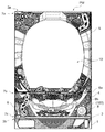
遊技盤10は、図5に示すように、ルータ加工等を施した矩形状の積層合板に、所定の図柄が印刷されたセルを貼り付けて成型される化粧板11を基板として構成される。化粧板11の前面には、飛送レール12a及び内レール12bが円弧状に固設されて遊技球が転動可能な略円形の遊技領域PAが区画形成されている。飛送レール12a及び内レール12bにより遊技球を遊技領域PAに誘導する発射通路12が形成され、この発射通路12における遊技球の出口開口12cの近傍位置(内レール12bの先端部)に、発射通路12を通って出口開口12cから遊技領域PA内に放出された遊技球が再び発射通路12に逆戻りするのを防止する球戻り防止装置13が設けられている。
As shown in FIG. 5, the game board 10 includes a decorative board 11 formed by attaching a cell printed with a predetermined pattern on a rectangular laminated plywood subjected to router processing or the like. On the front surface of the decorative plate 11, a substantially circular game area PA in which the flying rail 12a and the inner rail 12b are fixed in an arc shape and the game ball can roll is defined. A launching passage 12 that guides the game ball to the game area PA is formed by the flying rail 12a and the inner rail 12b, and the launching passage 12 launches at a position in the vicinity of the exit opening 12c of the game ball (the tip of the inner rail 12b). A ball return prevention device 13 is provided for preventing a game ball released from the outlet opening 12c into the game area PA through the passage 12 from returning to the launch passage 12 again.
遊技盤10の遊技領域PAには、多数本の遊技釘とともに、風車や各種の入賞装置14,15,16,17、遊技の進行状況に応じて各種の演出パターンの画像および図柄を表示する図柄表示装置18などの遊技構成部品が取り付けられている。また、遊技領域PAの下端には、各入賞装置に入賞せずに落下した遊技球を遊技盤10の裏面側へ排出させるアウト口19が設けられている。
In the game area PA of the game board 10, along with a large number of game nails, a windmill, various winning devices 14, 15, 16, and 17, and a pattern for displaying various effect pattern images and patterns according to the progress of the game. Game components such as the display device 18 are attached. Further, at the lower end of the game area PA, there is provided an out port 19 through which game balls that have fallen without winning in each winning device are discharged to the back side of the game board 10.
図3に示すように、前枠2の前面下部には、球皿ユニット6の背後に位置して遊技盤1
0と上下に整合し得る遊技補助盤20が形成されており、この遊技補助盤20の各部に、遊技盤10へ向けて遊技球を発射する発射機構21、前枠2の前後に連通して形成された賞球連絡通路22および溢れ球通路23、遊技領域PAに到達できずに発射通路12を戻ってくる遊技球(すなわちファール球)を回収する遊技球回収機構24などが設けられている。なお、詳細な図示を省略するが、発射機構21の前方には、この発射機構21の前面側を覆うカバー部材(図示せず)が着脱自在に取り付けられている。このカバー部材(図示せず)は、例えばABS樹脂などの樹脂材料を用いて射出成形等の成形手段で形成されている。
As shown in FIG. 3, the lower part of the front surface of the front frame 2 is located behind the ball tray unit 6 so that the game board 1
A game assisting board 20 that can be aligned vertically with 0 is formed, and each part of the game assisting board 20 communicates with the launching mechanism 21 that launches a game ball toward the game board 10 and the front and rear of the front frame 2. The formed prize ball communication passage 22 and overflow ball passage 23, and a game ball collection mechanism 24 for collecting game balls (that is, foul balls) that cannot return to the game area PA and return to the launch passage 12 are provided. . In addition, although detailed illustration is abbreviate | omitted, the cover member (not shown) which covers the front side of this launching mechanism 21 is attached to the front of the launching mechanism 21 so that attachment or detachment is possible. This cover member (not shown) is formed by molding means such as injection molding using a resin material such as ABS resin.
常には遊技補助盤20を覆って閉鎖状態に保持される球皿ユニット6の背面側には、図4に示すように、遊技補助盤20に設けられた各機器に対応した機構装置が装備されている。すなわち、発射機構21に対応して上球皿6aに貯留された遊技球を1球ずつ発射機構21に送り出す整流器50が設けられ、賞球連絡通路22に位置整合して賞球連絡通路22から流下する遊技球を上球皿6aに導く上球皿連絡ダクト27が設けられ、溢れ球通路23に位置整合して溢れ球通路23から流下する遊技球を下球皿6bに導く下球皿連絡ダクト28が設けられている。なお、球皿ユニット6の内部には、図7に示すように、上球皿6aから発射機構21(整流器50)へ遊技球を流下させる第1の球供給通路29aが形成される。また、球皿ユニット6の内部には、第1の球供給通路29aを流下する遊技球を図示しない球抜き機構により下球皿6bに導く球抜き通路29bが、下球皿連絡ダクト28に繋がって形成されている。
As shown in FIG. 4, a mechanism device corresponding to each device provided in the game assisting board 20 is provided on the back side of the ball tray unit 6 that always covers the game assisting board 20 and is held closed. ing. That is, a rectifier 50 is provided to send game balls stored in the upper ball tray 6 a one by one to the launching mechanism 21 corresponding to the launching mechanism 21, and is aligned with the winning ball connecting passage 22 to be aligned from the winning ball connecting passage 22. An upper ball tray connecting duct 27 is provided to guide the game balls flowing down to the upper ball tray 6a, and is aligned with the overflow ball passage 23 to guide the game balls flowing down from the overflow ball passage 23 to the lower ball tray 6b. A duct 28 is provided. In addition, as shown in FIG. 7, a first ball supply passage 29 a is provided inside the ball tray unit 6 to allow the game ball to flow down from the upper ball tray 6 a to the launching mechanism 21 (rectifier 50). Further, inside the ball tray unit 6, a ball discharge passage 29 b that guides the game balls flowing down the first ball supply passage 29 a to the lower ball tray 6 b by a ball removal mechanism (not shown) is connected to the lower ball tray connection duct 28. Is formed.
前枠2の裏面側には、図2に示すように、外枠1の内寸サイズよりも幾分小さめの矩形枠状に形成された裏セット盤30が着脱可能に取り付けられている。裏セット盤30は、遊技盤10の背後に位置する上部領域に、前後連通して開口する大型の窓口開口30aを有する枠状に形成されており、この窓口開口30aの上方に、遊技球を貯留する球貯留タンク31、及び球貯留タンク31と繋がって下方に若干傾斜するタンクレール32が設けられ、背面視における窓口開口30aの右側に、タンクレール32により前後各1列の整列状態で導かれた遊技球を遊技盤10における入賞状態に基づいて払い出す球払出装置33、球払出装置33から払い出された遊技球を球皿ユニット6の上球皿6aに導く球払出通路34などの賞球機構が設けられている。
As shown in FIG. 2, a back set board 30 formed in a rectangular frame shape somewhat smaller than the inner size of the outer frame 1 is detachably attached to the back side of the front frame 2. The back set board 30 is formed in a frame shape having a large window opening 30a that opens in communication with the front and rear in an upper region located behind the game board 10, and a game ball is placed above the window opening 30a. A sphere storage tank 31 for storage and a tank rail 32 that is connected to the sphere storage tank 31 and slightly tilted downward are provided, and are guided to the right side of the window opening 30a in rear view by the tank rail 32 in an aligned state in front and back. A ball payout device 33 for paying out the game balls that have been sent out based on the winning state on the game board 10, a ball payout passage 34 for guiding the game balls paid out from the ball payout device 33 to the upper ball tray 6 a of the ball tray unit 6, etc. A prize ball mechanism is provided.
このため、球払出装置33によって払い出され球払出通路34から賞球連絡通路22の後端部に流入した遊技球は、通常では、この賞球連絡通路22を前方に流下し、上球皿連絡ダクト27内の通路を通って上球皿6aに達する。一方で、上球皿6aが遊技球で満たされたときには、球払出装置33によって払い出された遊技球は、賞球連絡通路22から溢れ球誘導口(図示せず)を通過して溢れ球通路23を流下し、下球皿連絡ダクト28内の通路を通って下球皿6bに達する。
For this reason, the game balls that are paid out by the ball payout device 33 and flow into the rear end portion of the prize ball communication path 22 from the ball payout path 34 usually flow down forward in the prize ball communication path 22 and the upper ball tray. The upper ball tray 6 a is reached through the passage in the communication duct 27. On the other hand, when the upper ball tray 6a is filled with game balls, the game balls paid out by the ball payout device 33 pass through the overflow ball guide port (not shown) from the prize ball communication passage 22 and overflow balls. It flows down the passage 23 and reaches the lower ball tray 6b through the passage in the lower ball tray connecting duct 28.
また、裏セット盤30の背面には、制御装置、電子部品に電力を供給する電源ユニット41、パチンコ機PMの作動を統括的に制御する主制御装置(メイン制御基板)42、画像表示、効果照明および効果音等の遊技演出の制御を行う副制御装置(サブ制御基板)43、球払出装置33の作動を制御する払出制御装置44等の各種基板や電子部品などが取り付けられ、これらが図示省略するコネクタケーブルで接続されてパチンコ機PMが作動可能に構成される。
Further, on the back of the back set panel 30, a control device, a power supply unit 41 for supplying electric power to electronic components, a main control device (main control board) 42 for comprehensively controlling the operation of the pachinko machine PM, image display, effects Various substrates and electronic components such as a sub-control device (sub-control board) 43 that controls the game effects such as lighting and sound effects, and a pay-out control device 44 that controls the operation of the ball pay-out device 33 are attached. The pachinko machine PM is configured to be operable by being connected with a connector cable that is omitted.
このように概要構成されるパチンコ機PMにあって、遊技領域PAに発射された遊技球が各入賞装置に落入したときの遊技球の払い出し処理について、関連する各部の構成をもう少し詳しく説明する。遊技盤10に設けられる入賞装置には、その外観意匠や入賞時の動作を含めて種々の形態のものがあり、ゲージ設定に応じてどのような形態の入賞装置を用いるものであってもよいが、例えば図5に例示した遊技盤10では、一般入賞装置14
、始動入賞装置15、大入賞装置16,17の3種類の入賞装置を設けた例を示している。
With regard to the pachinko machine PM structured as described above, the configuration of each part related to the payout process of the game ball when the game ball launched into the game area PA falls into each winning device will be described in more detail. . There are various types of winning devices provided on the game board 10 including appearance design and operations at the time of winning, and any type of winning device may be used according to the gauge setting. However, in the game board 10 illustrated in FIG.
3 shows an example in which three types of winning devices, that is, a start winning device 15 and a large winning devices 16, 17 are provided.
一般入賞装置14は、遊技球が落入可能な入賞口14aを有する固定入賞具であり、この入賞口14aに落入したセーフ球はセーフ球通路を通って化粧板11の裏面側に排出され、該裏面側に設けられた入賞球検出器14s(図6を参照)を通過することによって入賞が検出されるようになっている。入賞球検出器14sは、遊技球の通過を検出可能な通過型センサである限り特に限定されず、例えば、磁気センサや光センサ、近接スイッチ等の非接触動作型でも、マイクロスイッチのような接触動作型でもよい(以下に示す入賞球検出器15s,16s,17sにおいても同様とする)。
The general winning device 14 is a fixed winning tool having a winning opening 14a into which a game ball can drop, and the safe ball that has dropped into the winning opening 14a is discharged to the back side of the decorative board 11 through the safe ball passage. The winning is detected by passing through a winning ball detector 14s (see FIG. 6) provided on the back side. The winning ball detector 14s is not particularly limited as long as it is a passing sensor that can detect the passing of a game ball. For example, a non-contact operation type such as a magnetic sensor, an optical sensor, a proximity switch, etc. It may be an operation type (the same applies to the winning ball detectors 15s, 16s, and 17s shown below).
始動入賞装置15は、遊技球が落入可能な入賞口15aを有し、図柄の変動開始の条件を定める入賞具であり、この入賞口15aに落入したセーフ球はセーフ球通路を通って化粧板11の裏面側に排出され、該裏面側に設けられた入賞球検出器15s(図6を参照)を通過することによって入賞が検出されるようになっている。
The start winning device 15 has a winning opening 15a into which a game ball can drop, and is a winning tool that determines the conditions for starting the fluctuation of the symbol. The safe ball that has entered the winning opening 15a passes through the safe ball passage. A winning is detected by being discharged to the back side of the decorative plate 11 and passing through a winning ball detector 15s (see FIG. 6) provided on the back side.
大入賞装置16,17は、遊技球が落入可能な入賞口16a,17aを有し、いわゆるアタッカー型の可動入賞装置であり、横長方形状の大入賞口16a,17aを覆う開閉扉が開閉可能に取り付けられている。開閉扉は通常閉止されており、遊技中における所定の入賞条件の下で特別遊技状態が成立したときに、開閉扉の上部が前方にほぼ90度倒されて大入賞口16a,17aが開放される。大入賞口16a,17aに落入したセーフ球はセーフ球通路を通って化粧板11の裏面側に排出され、該裏面側に領域開口に対応して設けられた入賞球検出器16s,17s(図6を参照)を通過することによって入賞が検出されるようになっている。なお、入賞球検出器14s,15s,16s,17sにより検出された遊技球は、遊技済み球排出通路を流下して遊技施設の遊技島の回収装置に排出される。
The grand prize winning devices 16 and 17 have prize winning openings 16a and 17a into which game balls can be dropped, and are so-called attacker type movable prize winning devices. The open / close doors covering the horizontal rectangular prize winning openings 16a and 17a are opened and closed. It is attached as possible. The door is normally closed, and when a special game state is established under a predetermined winning condition during the game, the upper part of the door is tilted forward approximately 90 degrees to open the large winning openings 16a, 17a. The The safe balls that have fallen into the big winning openings 16a, 17a pass through the safe ball passage and are discharged to the back side of the decorative board 11, and the winning ball detectors 16s, 17s (corresponding to the area openings on the back side) Winning is detected by passing through (see FIG. 6). Note that the game balls detected by the winning ball detectors 14s, 15s, 16s, and 17s flow down the game-completed ball discharge passage and are discharged to the game island collection device of the game facility.
以上のように構成されるパチンコ機PMは、外枠1が遊技施設の遊技島(設置枠台)に固定設置され、前枠2、ガラス扉5、球皿ユニット6等が閉鎖施錠された状態で遊技に供され、球皿ユニット6の上球皿6aに遊技球を貯留させて発射ハンドル8を回動操作することにより遊技が開始される。発射ハンドル8が回動操作されると、上球皿6aに貯留された遊技球が、球皿ユニット6の裏面側に配設される整流器50によって1球ずつ発射機構21に送り出され、発射機構21のハンマー21aにより遊技領域PAに打ち出されてパチンコゲームが展開される。
In the pachinko machine PM configured as described above, the outer frame 1 is fixedly installed on the game island (installation frame base) of the game facility, and the front frame 2, the glass door 5, the ball tray unit 6 and the like are closed and locked. The game is started by storing the game ball in the upper ball tray 6a of the ball tray unit 6 and turning the launching handle 8 to rotate. When the firing handle 8 is turned, the game balls stored in the upper ball tray 6a are sent one by one to the firing mechanism 21 by the rectifier 50 disposed on the back side of the ball tray unit 6, and the launch mechanism A hammer 21a is struck into the game area PA to develop a pachinko game.
さて、このように概要構成されるパチンコ機PMにおいて、正常な遊技では原則として遊技球1球につき1回のみ入賞球検出器への通過が検出されるものであるが、近年においては、入賞装置に落入した1個の遊技球を不正な操作によって入賞球検出器の導入口に連続して通過させて、多数の賞球を払い出させる不正入賞行為(ゴト行為)が頻発している。
Now, in the pachinko machine PM constructed as described above, in normal games, as a rule, the passing of the game ball to the winning ball detector is detected only once per game ball. There are frequent fraudulent prize winning actions (got action) in which a single gaming ball dropped into is continuously passed through the inlet of the winning ball detector by an illegal operation and a large number of prize balls are paid out.
この代表的な手口を概要説明すると、まず、所定長さを有する釣糸等の糸状体の一端側を遊技球に固着させ、この糸状体の他端側を不正行為者自身が掌で掴み、このような細工を施した遊技球(以下において「糸付球」と称する)を上球皿6aに貯留された他の遊技球の間に忍ばせて、他の遊技球とともに上球皿6aから1球ずつ順番に発射機構21へ供給させて発射機構21により発射通路12を通して遊技領域PA内へ送り込む。糸付球が遊技領域PAまで達すると、ガラス扉5の外側から強力な磁石を用いてこの遊技球を入賞装置(1回の賞球数が最も多い一般入賞装置14が狙われ易い傾向にある)まで誘導して当該入賞装置の入賞口へ落入させる。遊技球が入賞口からセーフ球通路に導かれて入賞球検出器の導入口を通過すると、主制御装置42により遊技球の入賞が検出されて球払出装
置33により入賞条件に応じた個数の賞球が上球皿6aへ払い出されることになる。不正行為者は、このように賞球が払い出されたことをもって、糸付球がターゲットである入賞球検出器へ到達したことを認識し、自身の掌に掴んでいる糸状体の他端側を手前に引っ張ったり奥側へ送り込んだりする操作をして、糸付球を入賞球検出器の導入口に何度も繰り返し通過させることで、遊技球の連続入賞を不正に検出させて多数の賞球を獲得している。これが、最近になって頻発している糸付球を用いた不正入賞行為の全貌である。
An outline of this typical technique is as follows. First, one end side of a filamentous body such as a fishing line having a predetermined length is fixed to a game ball, and the other end side of this filamentous body is grasped by a palm himself, A game ball (hereinafter referred to as “threaded ball”) that has been crafted in such a manner is held between other game balls stored in the upper ball tray 6a, and one ball from the upper ball tray 6a together with the other game balls. Each of them is sequentially supplied to the launching mechanism 21 and is sent into the game area PA through the launching passage 12 by the launching mechanism 21. When the ball with the thread reaches the game area PA, a strong magnet is used from the outside of the glass door 5 to win the game ball (the general winning device 14 having the largest number of award balls tends to be targeted). ) To drop into the winning opening of the winning device. When the game ball is guided from the winning opening to the safe ball passage and passes through the introducing opening of the winning ball detector, the winning of the gaming ball is detected by the main control device 42 and the number of awards corresponding to the winning conditions is detected by the ball payout device 33. The ball is paid out to the upper ball tray 6a. The fraudster recognizes that the threaded ball has reached the target winning ball detector when the prize ball is paid out in this way, and the other end side of the filament held in his palm By pulling the ball forward and sending it to the back side, the ball with thread is repeatedly passed through the entrance of the winning ball detector many times. Has won a prize ball. This is the whole picture of fraudulent prize-winning acts using threaded balls that have been occurring frequently recently.
そこで、このような不正入賞行為を防止すべく、第1実施形態のパチンコ機PMでは、整流器50に不正防止具(詳細は後述する受容部材100および切断部材110)が設けられている。以下、図7〜図10の各図を追加参照しながら、整流器50について説明する。整流器50は、図7〜図10に示すように、第1ケース部材60と、第2ケース部材70と、球送り部材80と、ソレノイド90とを有して構成される。
Therefore, in order to prevent such an illegal winning action, in the pachinko machine PM according to the first embodiment, the rectifier 50 is provided with an anti-fraud tool (a receiving member 100 and a cutting member 110 described later in detail). Hereinafter, the rectifier 50 will be described with reference to each of FIGS. As shown in FIGS. 7 to 10, the rectifier 50 includes a first case member 60, a second case member 70, a ball feeding member 80, and a solenoid 90.
第1ケース部材60は、図7および図9に示すように、ポリカーボネート(PC)等の樹脂材料を用いて、射出成形等の成形手段により板状に形成される。一方、第2ケース部材70は、図8および図10に示すように、ポリカーボネート(PC)等の樹脂材料を用いて、射出成形等の成形手段により開口部を有する箱状に形成される。第1ケース部材60と第2ケース部材70とは、それぞれの四隅に形成された係合部を互いに係合させることにより、箱型に組み立てられる。箱型に組み立てられた第1ケース部材60および第2ケース部材70の内部には、図9に示すように、上球皿6a(第1の球供給通路29a)から発射機構21へ遊技球を流下させる第2の球供給通路51が形成される。
As shown in FIGS. 7 and 9, the first case member 60 is formed into a plate shape by a molding means such as injection molding using a resin material such as polycarbonate (PC). On the other hand, as shown in FIGS. 8 and 10, the second case member 70 is formed in a box shape having an opening by a molding means such as injection molding using a resin material such as polycarbonate (PC). The first case member 60 and the second case member 70 are assembled into a box shape by engaging the engaging portions formed at the four corners of each other. Inside the first case member 60 and the second case member 70 assembled in a box shape, as shown in FIG. 9, a game ball is sent from the upper ball tray 6a (first ball supply passage 29a) to the launch mechanism 21. A second sphere supply passage 51 is formed to flow down.
第1ケース部材60の側壁部61の上部には、図9に示すように、第1の球供給通路29aの下流部と第2の球供給通路51の上流部51aとを連通させる球入口62が形成されており、第1の球供給通路29aの下流端に達した遊技球がこの球入口62を通過して第2の球供給通路51を流下するようになっている。また、第1ケース部材60の側壁部61の中間部には、球送り部材80に形成された揺動ストッパ(図示せず)を挿通させる揺動規制穴63が形成されている。
As shown in FIG. 9, a sphere inlet 62 that connects the downstream part of the first sphere supply passage 29 a and the upstream part 51 a of the second sphere supply passage 51 is provided at the upper part of the side wall part 61 of the first case member 60. The game ball that has reached the downstream end of the first ball supply passage 29a passes through the ball inlet 62 and flows down through the second ball supply passage 51. Further, a rocking restriction hole 63 through which a rocking stopper (not shown) formed in the ball feeding member 80 is inserted is formed in an intermediate portion of the side wall portion 61 of the first case member 60.
第2ケース部材70の側壁部71の内側には、図9に示すように、第2の球供給通路51の上流部51aを構成する通路床部72や傾斜壁部73等が形成され、通路床部72と傾斜壁部73との間には、第2の球供給通路51の上流部51aと下流部51bとを連通させる連通口52が形成される。また、第2ケース部材70の側壁部71には、図8に示すように、第2の球供給通路51の下流部51bと繋がる球出口74が形成されており、第2の球供給通路51の下流部51bに達した遊技球がこの球出口74を通過して発射機構21へ流下するようになっている。また、球出口74の図8における上側および右側の縁部には、逆L字形のガイド部75が球皿ユニット6の背面側へ突出するように形成されている。
As shown in FIG. 9, a passage floor portion 72, an inclined wall portion 73, etc. constituting the upstream portion 51 a of the second ball supply passage 51 are formed inside the side wall portion 71 of the second case member 70. A communication port 52 is formed between the floor portion 72 and the inclined wall portion 73 to allow the upstream portion 51a and the downstream portion 51b of the second sphere supply passage 51 to communicate with each other. Further, as shown in FIG. 8, the side wall portion 71 of the second case member 70 is formed with a sphere outlet 74 connected to the downstream portion 51 b of the second sphere supply passage 51, and the second sphere supply passage 51. The game ball that has reached the downstream portion 51b passes through the ball outlet 74 and flows down to the launching mechanism 21. Further, inverted L-shaped guide portions 75 are formed on the upper and right edges of the ball outlet 74 in FIG. 8 so as to protrude toward the back side of the ball tray unit 6.
球送り部材80は、図9に示すように、ポリアセタール樹脂(POM)等の樹脂材料を用いて、射出成形等の成形手段により図示する形状に形成され、球受容部81と、球送りレール部82と、棹部83とを有して構成される。また、球送り部材80は、軸部材85を用いて、箱型に組み立てられた第1ケース部材60および第2ケース部材70の内部に揺動自在に取り付けられる。球送り部材80の側部には、第1ケース部材60の揺動規制穴63に挿通される突起状の揺動ストッパ(図示せず)が形成され、揺動規制穴63の形状により球送り部材80の揺動範囲が規制されて、球受容部81が連通口52を閉鎖して球送りレール部82が球出口74を開放する球出口開放位置(図9の実線を参照)と、球受容部81が連通口52を開放して球送りレール部82が球出口74を閉鎖する球出口閉鎖位置(図9の二点鎖線を参照)との間で、球送り部材80が揺動可能に構成される。
As shown in FIG. 9, the ball feeding member 80 is formed into a shape shown in the figure by molding means such as injection molding using a resin material such as polyacetal resin (POM), and includes a ball receiving portion 81 and a ball feeding rail portion. 82 and a collar portion 83. Further, the ball feeding member 80 is swingably attached to the inside of the first case member 60 and the second case member 70 assembled in a box shape by using the shaft member 85. A protruding rocking stopper (not shown) that is inserted into the rocking restriction hole 63 of the first case member 60 is formed on the side of the ball feeding member 80. The swing range of the member 80 is restricted, the ball receiving portion 81 closes the communication port 52 and the ball feed rail portion 82 opens the ball outlet 74 (see the solid line in FIG. 9), and the ball The ball feed member 80 can swing between the ball outlet closed position (see the two-dot chain line in FIG. 9) in which the receiving portion 81 opens the communication port 52 and the ball feed rail portion 82 closes the ball outlet 74. Configured.
球受容部81は略L字形に形成され、球受容部81の下部に軸部材85が連結される。そして、球受容部81は、球送り部材80が球出口閉鎖位置に変位すると、球受容部81の上部が連通口52を開放して、連通口52を通過した遊技球を1球だけ受け入れて保持し、球送り部材80が球出口開放位置に変位すると、球受容部81の上部が連通口52を閉鎖して、保持した遊技球を球送りレール部82へ送るようになっている。
The ball receiving portion 81 is formed in a substantially L shape, and a shaft member 85 is connected to the lower portion of the ball receiving portion 81. Then, when the ball feeding member 80 is displaced to the ball outlet closed position, the ball receiving portion 81 opens the communication port 52 at the top of the ball receiving portion 81 and receives only one game ball that has passed through the communication port 52. When held and the ball feed member 80 is displaced to the ball outlet open position, the upper part of the ball receiving portion 81 closes the communication port 52 and feeds the held game ball to the ball feed rail portion 82.
球送りレール部82は、基端部が球受容部81の下部に繋がるとともに、先端部が第2ケース部材70の球出口74から球皿ユニット6の背面側へ突出して伸びる板状に形成される。そして、球送りレール部82は、球送り部材80が球出口閉鎖位置に変位すると、球出口74を閉鎖し、球送り部材80が球出口開放位置に変位すると、球出口74を開放して球受容部81から送られた遊技球を発射機構21へ流下させるようになっている。すなわち、球受容部81および球送りレール部82は、第2の球供給通路51の下流部51bを構成する。なお、球送りレール部82の上面は、先端部に向けて下傾するだけでなく、ガイド部75に向けても下傾しており、遊技球がガイド部75に沿って球送りレール部82上を転がるようになっている。
The ball feed rail portion 82 is formed in a plate shape whose base end portion is connected to the lower portion of the ball receiving portion 81 and whose tip portion extends from the ball outlet 74 of the second case member 70 to the back side of the ball tray unit 6. The The ball feed rail portion 82 closes the ball outlet 74 when the ball feed member 80 is displaced to the ball outlet closed position, and opens the ball outlet 74 when the ball feed member 80 is displaced to the ball outlet open position. The game ball sent from the receiving portion 81 is made to flow down to the launch mechanism 21. That is, the ball receiving portion 81 and the ball feed rail portion 82 constitute a downstream portion 51 b of the second ball supply passage 51. Note that the upper surface of the ball feed rail portion 82 is not only inclined downward toward the tip portion, but also inclined toward the guide portion 75, and the game ball moves along the guide portion 75 with the ball feed rail portion 82. It is supposed to roll up.
棹部83は、球受容部81の下端部から下方へ伸びる棒状に形成され、球送り部材80が球出口開放位置に変位すると、ソレノイド90に当接(もしくは隣接)するようになっている。棹部83の内部には、永久磁石86が取り付けられている。
The flange 83 is formed in a rod shape extending downward from the lower end of the ball receiving portion 81, and comes into contact with (or adjacent to) the solenoid 90 when the ball feed member 80 is displaced to the ball outlet open position. A permanent magnet 86 is attached inside the collar portion 83.
ソレノイド90は、図9に示すように、箱型に組み立てられた第1ケース部材60および第2ケース部材70の内部における棹部83の近傍に取り付けられる。ソレノイド90にはソレノイド制御基板91が電気的に接続されており、ソレノイド制御基板91から出力された駆動信号によりソレノイド90が駆動される。ソレノイド90がオン作動すると、ソレノイド90から発生した磁力を受けて、永久磁石86がソレノイド90から離れる方向へ移動し、永久磁石86が取り付けられた球送り部材80が球出口閉鎖位置に揺動変位するようになっている。一方、ソレノイド90がオフ作動すると、永久磁石86が重力の作用により下方へ移動し、永久磁石86が取り付けられた球送り部材80が球出口開放位置に揺動変位するようになっている。
As shown in FIG. 9, the solenoid 90 is attached in the vicinity of the flange 83 inside the first case member 60 and the second case member 70 assembled in a box shape. A solenoid control board 91 is electrically connected to the solenoid 90, and the solenoid 90 is driven by a drive signal output from the solenoid control board 91. When the solenoid 90 is turned on, the permanent magnet 86 is moved away from the solenoid 90 in response to the magnetic force generated from the solenoid 90, and the ball feed member 80 to which the permanent magnet 86 is attached is oscillated and displaced to the ball outlet closed position. It is supposed to be. On the other hand, when the solenoid 90 is turned off, the permanent magnet 86 is moved downward by the action of gravity, and the ball feed member 80 to which the permanent magnet 86 is attached is oscillated and displaced to the ball outlet open position.
ところで、第2の球供給通路51は、上流部51aから下流部51bにかけて概ね左右方向に伸びているが、下流部51bにおける球出口74の部分で延伸方向が直角に(前後方向に)折れ曲がる。このように(第2の)球供給通路51の延伸方向が変わる方向転換部の近傍に、より具体的には、整流器50における球出口74の近傍に、第1および第2の球供給通路29a,51に通された糸状体I(図8を参照)を受容して挟むことが可能な受容部材100と、受容部材100に受容された糸状体Iを切断可能な切断部材110が設けられる。
By the way, the second sphere supply passage 51 extends substantially in the left-right direction from the upstream portion 51a to the downstream portion 51b, but the extending direction is bent at a right angle (in the front-rear direction) at the portion of the sphere outlet 74 in the downstream portion 51b. Thus, in the vicinity of the direction changing portion where the extending direction of the (second) sphere supply passage 51 changes, more specifically, in the vicinity of the sphere outlet 74 in the rectifier 50, the first and second sphere supply passages 29a. , 51 is provided with a receiving member 100 capable of receiving and pinching the thread I (see FIG. 8), and a cutting member 110 capable of cutting the thread I received by the receiving member 100.
受容部材100は、図10に示すように、ステンレス鋼等の金属線材を用いて「山」の字形に曲げ形成され、糸状体導入部101と、糸状体受容部102と、第1取付部103aと、第2取付部103bとを有して構成される。糸状体導入部101は、受容部材100の基端部中央に位置して、受容部材100の基端部から先端側へ向かうにつれて間隔が狭くなるテーパー状に形成される。糸状体受容部102は、糸状体導入部101と繋がる受容部材100の先端側に位置して、細長いU字形に形成される。U字形に形成された糸状体受容部102の間隙部は、所定の糸状体I(例えば、釣糸や凧糸等)よりも若干細い幅に設定される。第1取付部103aは、受容部材100の一方の側端部に位置して、整流器50の突起部77aが挿通可能な円環状に形成される。第2取付部103bは、受容部材100の他方の側端部に位置して、第2取付部103bをネジ固定するためのネジ120が挿通可能な円環状に形成される。
As shown in FIG. 10, the receiving member 100 is bent and formed into a “mountain” shape using a metal wire such as stainless steel, and the thread-like body introducing portion 101, the thread-like body receiving portion 102, and the first mounting portion 103a. And a second mounting portion 103b. The filamentous body introducing portion 101 is located in the center of the base end portion of the receiving member 100 and is formed in a tapered shape whose interval becomes narrower from the base end portion of the receiving member 100 toward the distal end side. The thread-like body receiving part 102 is located on the distal end side of the receiving member 100 connected to the thread-like body introducing part 101 and is formed in an elongated U-shape. The gap between the U-shaped thread-like body receiving portions 102 is set to have a slightly narrower width than a predetermined thread-like body I (for example, a fishing line or a kite thread). The first attachment portion 103 a is located at one side end of the receiving member 100 and is formed in an annular shape through which the protrusion 77 a of the rectifier 50 can be inserted. The second attachment portion 103b is located in the other side end portion of the receiving member 100, and is formed in an annular shape into which a screw 120 for fixing the second attachment portion 103b can be inserted.
切断部材110は、図10に示すように、炭素鋼やステンレス鋼等の金属板材を用いて薄板状に形成され、本体部111と、刃部112とを有して構成される。本体部111には、整流器50の突起部77aが挿通可能な第1取付穴113aと、ネジ120が挿通可能な第2取付穴113bとが形成されている。刃部112は、本体部111の縁部に形成されて、受容部材100の糸状体受容部102に達した糸状体Iを切断可能に構成される。
As shown in FIG. 10, the cutting member 110 is formed in a thin plate shape using a metal plate material such as carbon steel or stainless steel, and includes a main body portion 111 and a blade portion 112. The main body 111 is formed with a first mounting hole 113a through which the protrusion 77a of the rectifier 50 can be inserted, and a second mounting hole 113b through which the screw 120 can be inserted. The blade 112 is formed at the edge of the main body 111 so as to be able to cut the thread I that has reached the thread receiving part 102 of the receiving member 100.
整流器50における第2ケース部材70の側壁部71の外側には、切断部材110の形状に合わせて形成された凹部76が形成されており、切断部材110がこの凹部76に受容された状態で整流器50に取り付けられるようになっている。凹部76には、切断部材110の第1取付穴113aおよび受容部材100の第1取付部103aに挿通される突起部77aと、ネジ120が螺合されるネジ穴77bとが形成される。なお、突起部77aの外径に対して、受容部材100の第1取付部103aの内径が若干大きくなるように形成される。これにより、突起部77aと第1取付部103aとの間の隙間の分だけ、受容部材100を弾性変形させることができるため、受容部材100の糸状体受容部102の間隙部よりも太い糸状体Iを受容部材100(糸状体受容部102)で受容して挟むことが可能となる。
A recess 76 is formed outside the side wall 71 of the second case member 70 in the rectifier 50 in accordance with the shape of the cutting member 110, and the rectifier is in a state where the cutting member 110 is received in the recess 76. 50 can be attached. The recess 76 is formed with a protrusion 77 a inserted into the first mounting hole 113 a of the cutting member 110 and the first mounting portion 103 a of the receiving member 100 and a screw hole 77 b into which the screw 120 is screwed. In addition, it forms so that the internal diameter of the 1st attaching part 103a of the receiving member 100 may become a little large with respect to the outer diameter of the projection part 77a. Accordingly, since the receiving member 100 can be elastically deformed by the gap between the protrusion 77a and the first mounting portion 103a, the filamentous body thicker than the gap of the filamentous body receiving portion 102 of the receiving member 100 is obtained. I can be received and pinched by the receiving member 100 (filament receiving portion 102).
第2ケース部材70の側壁部71の外側における凹部76の斜め上方には、受容部材100の先端部が挿入固定される受容部材固定部78が形成される。また、第2ケース部材70の側壁部71における凹部76の斜め下方には、凹部76と球出口74(すなわち、第2の球供給通路51における方向転換部)とに繋がって、受容部材100の糸状体導入部101および切断部材110の刃部112を露出させるスリット部79が形成される。このスリット部79は、整流器50に取り付けられた受容部材100(糸状体受容部102)の延伸方向に沿って斜め方向へ伸びるように形成される。
A receiving member fixing portion 78 into which the distal end portion of the receiving member 100 is inserted and fixed is formed obliquely above the concave portion 76 outside the side wall portion 71 of the second case member 70. In addition, diagonally below the recess 76 in the side wall 71 of the second case member 70, the recess 76 and the ball outlet 74 (that is, the direction changing portion in the second ball supply passage 51) are connected to the receiving member 100. A slit 79 is formed to expose the filamentous introduction part 101 and the blade part 112 of the cutting member 110. The slit portion 79 is formed to extend obliquely along the extending direction of the receiving member 100 (filamentous body receiving portion 102) attached to the rectifier 50.
受容部材100および切断部材110を整流器50に取り付けるには、まず、切断部材110の第1取付穴113aを整流器50の突起部77aに挿通させて、切断部材110を整流器50の凹部76に嵌め込む。次に、受容部材100の先端部を受容部材固定部78に挿入するとともに、受容部材100の第1取付部103aを整流器50の突起部77aに挿通させ、ワッシャ121とともにネジ120を受容部材100の第2取付部103bおよび切断部材110の第2取付穴113bに挿通させて整流器50のネジ穴77bに螺合させる。これにより、切断部材110が凹部76に受容された状態で整流器50に取り付けられ、受容部材100が切断部材110に重なった状態で切断部材110とともに整流器50に取り付けられる。
In order to attach the receiving member 100 and the cutting member 110 to the rectifier 50, first, the first mounting hole 113a of the cutting member 110 is inserted into the protrusion 77a of the rectifier 50, and the cutting member 110 is fitted into the recess 76 of the rectifier 50. . Next, while inserting the front-end | tip part of the receiving member 100 in the receiving member fixing | fixed part 78, the 1st attaching part 103a of the receiving member 100 is penetrated to the projection part 77a of the rectifier 50, and the screw 120 with the washer 121 is inserted. The second mounting portion 103b and the second mounting hole 113b of the cutting member 110 are inserted and screwed into the screw hole 77b of the rectifier 50. Accordingly, the cutting member 110 is attached to the rectifier 50 in a state where the cutting member 110 is received in the recess 76, and is attached to the rectifier 50 together with the cutting member 110 in a state where the receiving member 100 overlaps the cutting member 110.
このようにして受容部材100および切断部材110が取り付けられた整流器50において、上球皿6aに貯留された遊技球は、第1の球供給通路29aを流下して球入口62を通過し、第2の球供給通路51の上流部51aを流下して球送り部材80の球受容部81によって閉鎖された連通口52に達する。この状態で、発射ハンドル8が回動操作されると、ソレノイド90がオン作動とオフ作動を繰り返して、第2の球供給通路51の連通口52に達した遊技球が1球ずつ発射機構21に供給される。
In the rectifier 50 to which the receiving member 100 and the cutting member 110 are attached in this way, the game balls stored in the upper ball tray 6a flow down the first ball supply passage 29a, pass through the ball inlet 62, and It flows down the upstream portion 51 a of the second ball supply passage 51 and reaches the communication port 52 closed by the ball receiving portion 81 of the ball feeding member 80. In this state, when the launching handle 8 is turned, the solenoid 90 repeats the on-operation and the off-operation, and the game balls that have reached the communication port 52 of the second ball supply passage 51 are launched one by one. To be supplied.
このとき、ソレノイド90がオン作動すると、球送り部材80が球出口閉鎖位置に揺動変位するため、球受容部81の上部で受け止められていた遊技球は連通口52を通過し、連通口52を開放した球受容部81が連通口52を通過した遊技球を1球だけ受け入れて保持する。一方、ソレノイド90がオフ作動すると、球送り部材80が球出口開放位置に揺動変位するため、球受容部81に保持された遊技球は、球送りレール部82に送られて第2の球供給通路51の下流部51bを流下し、球出口74から発射機構21へ送り出される。
At this time, when the solenoid 90 is turned on, the ball feeding member 80 swings and displaces to the ball outlet closed position, so that the game ball received at the upper part of the ball receiving portion 81 passes through the communication port 52 and passes through the communication port 52. The ball receiving portion 81 with the opening opened receives and holds only one game ball that has passed through the communication port 52. On the other hand, when the solenoid 90 is turned off, the ball feeding member 80 swings and displaces to the ball outlet open position, so that the game ball held by the ball receiving portion 81 is sent to the ball feeding rail portion 82 and the second ball. It flows down the downstream portion 51 b of the supply passage 51 and is sent out from the ball outlet 74 to the firing mechanism 21.
このようにして、第1の球供給通路29aおよび第2の球供給通路51を流下する遊技球が整流器50により1球ずつ発射機構21に送り出され、発射機構21のハンマー21aにより遊技領域PAに打ち出される。そして、発射機構21の発射動作ごとにソレノイド90をオン・オフ作動させ、球送り部材80を球出口閉鎖位置と球出口開放位置とに交互に変位させることで、発射機構21が発射動作を行うごとに、第1の球供給通路29aおよび第2の球供給通路51を流下する遊技球が1球ずつ連続的に発射機構21へ供給される。
In this way, the game balls flowing down the first ball supply passage 29a and the second ball supply passage 51 are sent one by one to the firing mechanism 21 by the rectifier 50, and into the game area PA by the hammer 21a of the launch mechanism 21. Be launched. Then, each time the firing mechanism 21 performs a firing operation, the solenoid 90 is turned on / off, and the ball feeding member 80 is alternately displaced between the ball exit closed position and the ball exit open position, whereby the firing mechanism 21 performs the firing operation. Each time, the game balls flowing down the first ball supply passage 29a and the second ball supply passage 51 are continuously supplied to the launch mechanism 21 one by one.
上球皿6aに貯留された遊技球の中に糸付球が存在すると、当該糸付球は、他の遊技球とともに上球皿6aから第1の球供給通路29aおよび第2の球供給通路51を流下して、整流器50により発射機構21に送り出され、発射機構21のハンマー21aにより遊技領域PAに打ち出される。このとき、糸付球に固着された糸状体Iは、第1の球供給通路29aおよび第2の球供給通路51に通された状態で、不正行為者に引っ張られると真直ぐに伸びようとする。本実施形態では、(第2の)球供給通路51の延伸方向が変わる方向転換部の近傍に、より具体的には、整流器50における球出口74の近傍に、受容部材100が設けられている。そのため、球出口74の近傍において真直ぐに伸びようとする糸状体Iは、球出口74の縁部に形成されたガイド部75を伝ってスリット部79に達し、図8に示すように、受容部材100の糸状体導入部101から糸状体受容部102の間隙部に導かれる。
When a ball with a thread is present in the game balls stored in the upper ball tray 6a, the ball with the thread is moved together with the other game balls from the upper ball tray 6a to the first ball supply passage 29a and the second ball supply passage. 51 flows down to the launching mechanism 21 by the rectifier 50, and is launched into the game area PA by the hammer 21a of the launching mechanism 21. At this time, the filament I fixed to the threaded ball tends to extend straight when pulled by an unauthorized person while being passed through the first ball supply passage 29a and the second ball supply passage 51. . In the present embodiment, the receiving member 100 is provided in the vicinity of the direction changing portion where the extending direction of the (second) sphere supply passage 51 changes, more specifically, in the vicinity of the sphere outlet 74 in the rectifier 50. . Therefore, the filament I that tries to extend straight in the vicinity of the ball outlet 74 reaches the slit portion 79 along the guide portion 75 formed at the edge of the ball outlet 74, and as shown in FIG. 100 thread guides 101 are guided to the gap of the thread receiving part 102.
ここで、糸状体Iが糸状体受容部102の間隙部よりも太い場合、糸状体Iにより糸状体受容部102の間隙部が押し広げられて受容部材100(糸状体受容部102)が弾性変形するので、受容部材100は、受容部材100の弾性力による遊技球の自重よりも強い力で、受容した糸状体Iを挟むことができる。そのため、糸状体Iが受容部材100に引っ掛かった状態となり、遊技領域PAに打ち出された糸付球を無理に引き上げることはできても、下方へ移動させることはできなくなる。また、糸状体Iが強く引っ張られた場合や、糸状体Iが糸状体受容部102の間隙部と同等の太さかこれよりも細い場合、糸状体受容部102の間隙部に導かれた糸状体Iは、受容部材100と重なって設けられた切断部材110の刃部112まで達し、切断部材110が糸状体Iを切断することができる。このようにして、糸付球を用いた不正入賞行為を抑止することができる。
Here, when the filament I is thicker than the gap of the filament receiver 102, the gap of the filament receiver 102 is expanded by the filament I, and the receiving member 100 (filament receiver 102) is elastically deformed. Therefore, the receiving member 100 can pinch the received filament I with a force stronger than the weight of the game ball due to the elastic force of the receiving member 100. Therefore, the filament I is in a state of being caught by the receiving member 100, and even if the threaded ball launched into the game area PA can be forcibly pulled up, it cannot be moved downward. Further, when the filament I is pulled strongly, or when the filament I is the same thickness as or thinner than the gap of the filament receiver 102, the filament guided to the gap of the filament receiver 102 I reaches the blade 112 of the cutting member 110 provided so as to overlap with the receiving member 100, and the cutting member 110 can cut the filament I. In this way, an illegal winning action using a threaded ball can be suppressed.
以上説明したように、第1実施形態によれば、(第2の)球供給通路51の延伸方向が変わる方向転換部の近傍に、糸状体Iを受容して挟むことが可能な受容部材100が設けられるため、簡便な構成の受容部材100により、不正行為者に引っ張られる等して真直ぐに伸びようとする糸状体Iを、(第2の)球供給通路51の延伸方向が変わる方向転換部において容易に捕捉することができる。そのため、簡便な構成で、糸状体Iおよび糸状体Iの付いた遊技球の自由な動きを拘束することが可能となり、糸状体Iの付いた遊技球を不正に操作して遊技球の入賞を検出させる不正入賞行為を効果的に抑止することができる。
As described above, according to the first embodiment, the receiving member 100 capable of receiving and sandwiching the filament I in the vicinity of the direction changing portion where the extending direction of the (second) sphere supply passage 51 changes. Therefore, by the receiving member 100 having a simple configuration, the filament I that tends to be stretched straight by being pulled by a fraudster or the like changes the direction in which the extending direction of the (second) ball supply passage 51 changes. It can be easily captured at the part. Therefore, it becomes possible to restrict the free movement of the filament I and the game ball with the filament I with a simple configuration, and the game ball with the filament I can be illegally operated to win a prize for the game ball. The illegal winning action to be detected can be effectively suppressed.
また、(第2の)球供給通路51の延伸方向が変わる方向転換部の近傍に、受容部材100に受容された糸状体Iを切断可能な切断部材110が設けられることで、糸状体Iが強く引っ張られた場合や、糸状体Iが比較的細い場合に、受容部材100に受容された糸状体Iを切断することが可能となり、糸状体Iの付いた遊技球を不正に操作して遊技球の入賞を検出させる不正入賞行為をより効果的に抑止することができる。
In addition, a cutting member 110 capable of cutting the filament I received by the receptor member 100 is provided in the vicinity of the direction changing portion where the extending direction of the (second) sphere supply passage 51 changes. When strongly pulled or when the filament I is relatively thin, the filament I received by the receiving member 100 can be cut, and the game ball with the filament I is illegally operated to play a game. An illegal winning action that detects a winning of a ball can be more effectively suppressed.
また、切断部材110が凹部76に受容された状態で整流器50に取り付けられ、受容部材100が切断部材110とともに整流器50に取り付けられ、整流器50における凹部76と(第2の)球供給通路51とに繋がって、受容部材100の糸状体導入部101
および切断部材110の刃部112を露出させるスリット部79が形成される。このようにすれば、糸状体Iを切断するのに必要な部分だけ露出させることが可能となり、受容部材100および切断部材110が取り付けられた整流器50を取り扱ったときに、切断部材110に触れて怪我をするのを防止することができる。
The cutting member 110 is attached to the rectifier 50 in a state where the cutting member 110 is received in the recess 76, and the receiving member 100 is attached to the rectifier 50 together with the cutting member 110, and the recess 76 in the rectifier 50 and the (second) ball supply passage 51 Connected to the thread-like body introducing portion 101 of the receiving member 100.
And the slit part 79 which exposes the blade part 112 of the cutting member 110 is formed. If it does in this way, it will become possible to expose only the part required in order to cut the filament I, and when the rectifier 50 to which the receiving member 100 and the cutting member 110 are attached is handled, the cutting member 110 is touched. Injury can be prevented.
なお、上述の第1実施形態において、受容部材100における糸状体受容部102の内側部分に、ヤスリ目を形成するようにしてもよい。このようにすれば、糸状体Iと糸状体受容部102との間の摩擦力が増えるので、受容部材100から糸状体Iが抜けるのを防止することができる。また、受容部材100における糸状体受容部102の内側部分に、受容部材100の先端側に向けて返しの付いた突起部を形成するようにしてもよい。このようにしても、受容部材100から糸状体Iが抜けるのを防止することができる。
In the first embodiment described above, a file may be formed on the inner side of the filamentous body receiving portion 102 of the receiving member 100. In this way, since the frictional force between the thread-like body I and the thread-like body receiving portion 102 increases, it is possible to prevent the thread-like body I from coming off the receiving member 100. Further, a protruding portion that is turned back toward the distal end side of the receiving member 100 may be formed on the inner side portion of the filament-shaped receiving portion 102 in the receiving member 100. Even in this case, it is possible to prevent the filament I from coming off from the receiving member 100.
また、上述の第1実施形態において、受容部材100の糸状体受容部102が細長いU字形に形成されているが、これに限られるものではなく、例えば、糸状体受容部の間隙部が迷路状にもしくは渦巻き状に伸びるように糸状体受容部を形成してもよい。このようにすれば、糸状体受容部の間隙部の形状が複雑になるので、受容部材から糸状体Iが抜けるのを防止することができる。
Further, in the first embodiment described above, the filament receiving part 102 of the receiving member 100 is formed in an elongated U-shape. However, the present invention is not limited to this. For example, the gap of the filament receiving part is a maze. Alternatively, the thread-like body receiving portion may be formed so as to extend in a spiral shape. By doing so, the shape of the gap portion of the filamentous body receiving portion becomes complicated, so that the filamentous body I can be prevented from coming off from the receiving member.
また、上述の第1実施形態において、図11に示すように、切断部材110を設けずに、受容部材100だけを設けるようにしてもよい。なおこの場合、整流器50における第2ケース部材70の側壁部71の外側に、凹部76を形成する必要はないが、受容部材100を整流器50に取り付けるため、第1実施形態の場合と同様にして、突起部77aと、ネジ穴77bと、受容部材固定部78と、スリット部79とを形成する。またこの場合、ニクロム線を用いて受容部材100を形成し、ニクロム線を用いた受容部材100に対して所定時間ごとに通電させるようにしてもよい。このようにすれば、ニクロム線を用いた受容部材100が発熱するため、受容部材100が挟んだ樹脂製の糸状体(釣糸等)を切断することが期待できる。
In the first embodiment described above, as shown in FIG. 11, only the receiving member 100 may be provided without providing the cutting member 110. In this case, it is not necessary to form the recess 76 on the outside of the side wall 71 of the second case member 70 in the rectifier 50. However, since the receiving member 100 is attached to the rectifier 50, the same as in the case of the first embodiment. The protrusion 77a, the screw hole 77b, the receiving member fixing part 78, and the slit part 79 are formed. In this case, the receiving member 100 may be formed using a nichrome wire, and the receiving member 100 using the nichrome wire may be energized every predetermined time. In this way, since the receiving member 100 using nichrome wire generates heat, it can be expected to cut the resinous thread (fishing line or the like) sandwiched between the receiving members 100.
また、上述の第1実施形態において、受容部材100が金属線材を用いて形成されているが、これに限られるものではなく、例えば、金属板材を用いて形成されてもよく、糸状体Iを受容して挟むことが可能な構成であればよい。
In the first embodiment described above, the receiving member 100 is formed using a metal wire. However, the receiving member 100 is not limited to this. For example, the receiving member 100 may be formed using a metal plate. Any configuration that can be received and sandwiched is acceptable.
また、上述の第1実施形態において、第1の球供給通路29aが直線状に形成されているが、これに限られるものではなく、第1の球供給通路29aの途中がループ形状であってもよい。このようにすれば、第1の球供給通路29aに通された糸状体がループ形状の部分で巻き付くため、糸状体の付いた遊技球を不正に操作して遊技球の入賞を検出させる不正入賞行為をより効果的に抑止することができる。
In the first embodiment described above, the first sphere supply passage 29a is formed in a straight line. However, the present invention is not limited to this, and the middle of the first sphere supply passage 29a has a loop shape. Also good. In this way, since the filament passed through the first ball supply passage 29a wraps around the loop-shaped portion, the illegal operation of detecting the winning of the game ball by illegally operating the game ball with the filament is performed. The winning action can be more effectively deterred.
また、上述の第1実施形態において、整流器50における球出口74の近傍に、受容部材100および切断部材110が設けられているが、これに限られるものではなく、第1の球供給通路29aと第2の球供給通路51との境界部で通路形状が屈曲する球入口62の近傍に、受容部材および切断部材が設けられてもよい。
In the first embodiment described above, the receiving member 100 and the cutting member 110 are provided in the vicinity of the ball outlet 74 in the rectifier 50. However, the present invention is not limited to this, and the first ball supply passage 29a and A receiving member and a cutting member may be provided in the vicinity of the sphere inlet 62 where the passage shape is bent at the boundary with the second sphere supply passage 51.
また、上述の第1実施形態において、整流器50以外にも、不正入賞行為を防止するための不正防止具を設けることが可能である。そこで、第1実施形態に係るパチンコ機PMの変形例について説明する。
Further, in the first embodiment described above, in addition to the rectifier 50, it is possible to provide a fraud prevention tool for preventing an illegal winning action. Therefore, a modification of the pachinko machine PM according to the first embodiment will be described.
第1の変形例では、遊技補助盤に設けられた遊技球発射装置及び遊技球回収機構を主体として、不正防止構造が構成されている。以下、図12〜図18の各図を追加参照しながら、第1の変形例に係る遊技球発射装置150及び遊技球回収機構200について説明す
る。ここで、図12は、第1の変形例に係る遊技球発射装置150及び遊技球回収機構200が設けられた遊技補助盤240を示す正面図、図13は遊技球発射装置150及び遊技球回収機構200においてハンマーが発射待機位置にある状態の正面図、図14は遊技球発射装置150及び遊技球回収機構200においてハンマーが発射完了位置にある状態の正面図、図15は図13における矢印XV−XVに沿って示す要部断面図、図16は図14における矢印XVI−XVIに沿って示す要部断面図、図17は図13の状態において遊技球発射装置150及び遊技球回収機構200を背面から見た図、図18は図14の状態において遊技球発射装置150及び遊技球回収機構200を背面から見た図である。
In the first modified example, a fraud prevention structure is configured mainly by a game ball launching device and a game ball collection mechanism provided on the game auxiliary board. Hereinafter, the game ball launching apparatus 150 and the game ball collection mechanism 200 according to the first modification will be described with additional reference to each of FIGS. Here, FIG. 12 is a front view showing a game ball launching apparatus 150 and a game auxiliary board 240 provided with the game ball collecting mechanism 200 according to the first modification, and FIG. 13 is a game ball launching apparatus 150 and a game ball collecting. FIG. 14 is a front view of the mechanism 200 with the hammer in the firing standby position, FIG. 14 is a front view of the game ball launching apparatus 150 and the game ball collection mechanism 200 with the hammer in the firing completion position, and FIG. 15 is an arrow XV in FIG. 16 is a cross-sectional view of the main part shown along -XV, FIG. 16 is a cross-sectional view of the main part shown along arrow XVI-XVI in FIG. 14, and FIG. 17 shows the game ball launcher 150 and the game ball collecting mechanism 200 in the state shown in FIG. FIG. 18 is a view seen from the back, and FIG. 18 is a view seen from the back of the game ball launcher 150 and the game ball collection mechanism 200 in the state of FIG.
遊技球発射装置150は、その構成を大別すると、遊技球の発射操作を行う発射ハンドル8、遊技球を発射する発射機構170、発射された遊技球を発射通路12に案内する発射レール部180、及び発射機構170の作動を制御する払出制御装置44などから構成される。
The configuration of the game ball launching apparatus 150 is roughly divided into a launch handle 8 for launching a game ball, a launch mechanism 170 for launching the game ball, and a launch rail unit 180 for guiding the launched game ball to the launch passage 12. , And a dispensing control device 44 for controlling the operation of the firing mechanism 170.
発射ハンドル8は、上述の第1実施形態における発射ハンドル8と同様の構成であるが、詳細には、パチンコ機PMの機体から前方に突出するハンドルベース161(図4を参照)と、このハンドルベース161の前方に回動操作可能に設けられた回動レバー162(図1を参照)と、ハンドルベース161内に設けられ回動レバー162の回動操作量を検出するポテンショメータ等の角度検出器163(図6の二点鎖線を参照)と、遊技者が発射ハンドル8(回動レバー162)に接触しているか否かを検出するタッチ検出器164(図6の二点鎖線を参照)などを備えて構成されている。なお、角度検出器163及びタッチ検出器164の検出信号は払出制御装置44に入力されており、払出制御装置44はタッチ検出器164からの検出信号から遊技者が発射ハンドル8に触れているか否かを判定し、角度検出器163からの検出信号から回動レバー162の回動操作量を検知して、これらの検出信号に基づいて発射機構170の作動を制御する。
The launch handle 8 has the same configuration as the launch handle 8 in the first embodiment described above, but in detail, a handle base 161 (see FIG. 4) that protrudes forward from the body of the pachinko machine PM, and the handle A rotation lever 162 (see FIG. 1) provided in front of the base 161 so as to be rotatable, and an angle detector such as a potentiometer that is provided in the handle base 161 and detects a rotation operation amount of the rotation lever 162. 163 (refer to the two-dot chain line in FIG. 6), a touch detector 164 (refer to the two-dot chain line in FIG. 6) for detecting whether or not the player is in contact with the firing handle 8 (rotating lever 162), etc. It is configured with. Note that the detection signals of the angle detector 163 and the touch detector 164 are input to the payout control device 44, and the payout control device 44 determines whether or not the player touches the launch handle 8 based on the detection signal from the touch detector 164. And detecting the amount of rotation of the rotation lever 162 from the detection signal from the angle detector 163, and controlling the operation of the firing mechanism 170 based on these detection signals.
発射機構170は、遊技補助盤20の前面側に設けられ発射機構170の取り付けベースとなる平板状のベースプレート171と、このベースプレート171の前面側に位置して遊技盤10の盤面とほぼ平行な面内で揺動可能なように設けられたハンマー172と、このハンマー172を揺動作動させるロータリソレノイド173(図6の二点鎖線を参照)とを備えて構成される。
The launching mechanism 170 is provided on the front side of the game assisting board 20 and is a flat base plate 171 serving as a mounting base for the launching mechanism 170, and a plane that is located on the front side of the base plate 171 and is substantially parallel to the board surface of the gaming board 10. And a rotary solenoid 173 (see a two-dot chain line in FIG. 6) for swinging the hammer 172.
ベースプレート171は、例えば薄板状の鋼板を切断及び孔あけ加工し所要の表面処理を施して形成される。ロータリソレノイド173は、複数のビス174を用いてビス止めされることでベースプレート171の背面側に取り付けられ、本体部分がベースプレート171の背面側に突出している。ロータリソレノイド173の駆動軸173aは、ベースプレート171に形成された駆動軸挿通孔(図示せず)を通過してベースプレート171の前面側に達するように構成されており、この駆動軸173aをハンマー172の取り付け孔(図示せず)に挿通させて、駆動軸173a先端のネジ部を固定ナット175で螺着させることで、この駆動軸173aにハンマー172が一体的に連結されるようになっている。このようにして、ハンマー172はベースプレート171の前面側に取り付けられ、払出制御装置44からの指令に基づいてロータリソレノイド173が作動することにより、ベースプレート171の前面側で駆動軸173aを中心として上下に揺動するようになっている。
The base plate 171 is formed, for example, by cutting and punching a thin steel plate and performing a required surface treatment. The rotary solenoid 173 is attached to the back side of the base plate 171 by being screwed using a plurality of screws 174, and the main body portion protrudes to the back side of the base plate 171. The drive shaft 173 a of the rotary solenoid 173 is configured to pass through a drive shaft insertion hole (not shown) formed in the base plate 171 and reach the front surface side of the base plate 171. The drive shaft 173 a is connected to the hammer 172. The hammer 172 is integrally connected to the drive shaft 173a by inserting it through an attachment hole (not shown) and screwing the screw portion at the tip of the drive shaft 173a with the fixing nut 175. In this way, the hammer 172 is attached to the front surface side of the base plate 171, and the rotary solenoid 173 is operated based on a command from the payout control device 44, so that the drive shaft 173a is centered on the front surface side of the base plate 171. It swings.
ハンマー172は、「く」字状に屈曲して細長く延びるハンマーアーム部172aと、その上方に舌片状に突出する緩衝アーム部172bと、両アーム部が交わる位置に形成されロータリソレノイド173の駆動軸173aに固定される本体部172cとを備えて構成されており、ハンマーアーム部172aの先端には遊技球を叩打する樹脂製のハンマーヘッド172dが嵌着されている。
The hammer 172 is formed at a position where the hammer arm portion 172a that is bent in a “<” shape and extends elongated, a buffer arm portion 172b that protrudes in a tongue-like shape above the arm portion, and the two arm portions intersect with each other. A main body portion 172c fixed to the shaft 173a is provided, and a hammer head 172d made of resin for hitting a game ball is fitted to the tip of the hammer arm portion 172a.
また、ベースプレート171の前面には、ハンマーヘッド172dの打撃位置から下方に退避させた揺動位置でハンマーアーム部172aを弾性的に受け止める下部ストッパ176や、打撃位置をわずかに超えた揺動位置で緩衝アーム部172bを弾性的に受け止める上部ストッパ177などが取り付けられている。そのため、ハンマー172は、ロータリソレノイド173の駆動軸173aを中心として、ハンマーアーム部172aが下部ストッパ176に当接して揺動規制された下方限界位置(これを「発射待機位置」と称する)と、緩衝アーム部172bが上部ストッパ177に当接して揺動規制された上方限界位置(これを「発射完了位置」と称する)との間で揺動変位可能である。
Also, on the front surface of the base plate 171, there is a lower stopper 176 that elastically receives the hammer arm portion 172a at a swing position retracted downward from the hit position of the hammer head 172d, and a swing position that slightly exceeds the hit position. An upper stopper 177 and the like for elastically receiving the buffer arm portion 172b are attached. Therefore, the hammer 172 has a lower limit position (referred to as a “firing standby position”) in which the hammer arm portion 172a abuts against the lower stopper 176 and is controlled to swing around the drive shaft 173a of the rotary solenoid 173. The buffer arm portion 172b can swing and displace between an upper limit position (referred to as a “firing completion position”) in which the swing arm 172b abuts on the upper stopper 177 and is controlled to swing.
発射レール部180は、ベースプレート171の前面側に設けられて整流器50から供給された遊技球B(図12及び図13等を参照)をハンマーヘッド172dの打撃位置に合わせて一時保持するガイドホルダ181と、このガイドホルダ181から斜め上方に延びる平断面視凹状の発射レール182とを備えて構成される。
The firing rail portion 180 is provided on the front surface side of the base plate 171 and temporarily holds the game ball B (see FIGS. 12 and 13 and the like) supplied from the rectifier 50 in accordance with the striking position of the hammer head 172d. And a firing rail 182 having a concave shape in plan view extending obliquely upward from the guide holder 181.
発射レール182は、左斜め上方に延びる中央通路壁183と、この中央壁を挟んで左側及び右側に遊技球の直径よりも幾分大き目の間隔をおいて略平行に立設された左側通路壁184及び右側通路壁185とを有し、これらの通路壁183,184,185に囲まれてハンマー172により打ち出された遊技球が通過可能な球通路186が画形されている。この発射レール182は、ガイドホルダ181の上端位置から飛送レール12aと内レール12bとの間の発射通路12に向けて(すなわち飛送レール12aの下端近傍のレール面よりも上方に向けて)左斜め上方に延びて設けられる。発射レール182の上端の発射口182aは、収容枠の支持面よりも上方に延びて遊技盤10前面のアウト口19のほぼ左側方にあたる高さ位置で開口している。
The firing rail 182 has a central passage wall 183 that extends obliquely upward to the left, and a left passage wall that is erected substantially parallel to the left and right sides with a gap slightly larger than the diameter of the game ball across the central wall. 184 and a right passage wall 185, and a ball passage 186 that is surrounded by these passage walls 183, 184, 185 and through which a game ball launched by the hammer 172 can pass is defined. The firing rail 182 is directed from the upper end position of the guide holder 181 toward the firing passage 12 between the flying rail 12a and the inner rail 12b (that is, upward from the rail surface near the lower end of the flying rail 12a). It is provided to extend diagonally to the left. The launch port 182a at the upper end of the launch rail 182 extends upward from the support surface of the housing frame and opens at a height position that is substantially on the left side of the out port 19 on the front surface of the game board 10.
また、発射レール182における発射口182aの左側には、上方に開口するファール球回収口191が形成されたファール球回収樋190が設けられており、遊技領域PAに到達できずに発射通路12を戻ってくる遊技球(すなわちファール球)がファール球回収口191に落入するようになっている。このファール球回収樋190の内部に形成されたファール球回収通路192は、下球皿6bに繋がる溢れ球通路243と連通しており、ファール球回収口191に落入したファール球はファール球回収通路192を流下して溢れ球通路243に導かれ、下球皿連絡ダクト28を経て下球皿6bに至るようになっている。
Further, on the left side of the launch port 182a in the launch rail 182, there is provided a foul ball collection basket 190 in which a foul ball collection port 191 opening upward is formed, and the launch path 12 is not reached without reaching the game area PA. A returning game ball (that is, a foul ball) falls into the foul ball collection port 191. A foul ball collection passage 192 formed inside the foul ball collection basket 190 communicates with an overflow ball passage 243 connected to the lower ball dish 6b, and the foul ball dropped into the foul ball collection port 191 is collected. It flows down the passage 192, is guided to the overflow ball passage 243, and reaches the lower ball tray 6b via the lower ball tray connecting duct 28.
一方、遊技球回収機構200は、ベースプレート171の背面側に設けられ発射機構170のハンマー172と連結されるアーム部材210と、このアーム部材210を介してハンマー172の揺動が伝達されることで発射レール182の球通路186を開閉する開閉弁部材220と、発射レール182の左側通路壁184に隣接して設けられ発射レール182の球通路186と連通する遊技球回収樋230とを主体に構成される。
On the other hand, the game ball collecting mechanism 200 is provided with an arm member 210 provided on the back side of the base plate 171 and connected to the hammer 172 of the firing mechanism 170, and the swing of the hammer 172 is transmitted through the arm member 210. An open / close valve member 220 that opens and closes the ball passage 186 of the launch rail 182 and a game ball collection basket 230 that is provided adjacent to the left passage wall 184 of the launch rail 182 and communicates with the ball passage 186 of the launch rail 182 are mainly configured. Is done.
アーム部材210は、細長い棒状のアーム本体211と、このアーム本体211の下端部から屈曲して略水平に延びる基端部212と、アーム本体211の上端部に形成された略円弧状のロッド支持部213とを備えて構成されており、ハンマー172と開閉弁部材220との間を連繋して揺動可能に設けられ、ハンマー172の揺動による押圧力を開閉弁部材220に伝達するようになっている。なお、上記ベースプレート171には緩衝アーム部172bの揺動軌跡及び揺動角度範囲に合わせた円弧状のガイド溝171aが形成され、緩衝アーム172bから後方に突設される円筒状のガイドピン219がこのガイド溝171a内に係合されてベースプレート171の背面側に達するように構成されており、このガイドピン219をアーム部材210の基端部212から下方に向けて平行に突設された左右一対の突出部214,214の間隙に圧入固定することで、ハンマー172と
アーム部材210とがベースプレート171を間に挟んで連結されている。このようにアーム部材210はハンマー172に連結されることで、ハンマー172と一体となって上下に揺動するようになっている。
The arm member 210 includes an elongated rod-shaped arm main body 211, a base end portion 212 that is bent from the lower end portion of the arm main body 211 and extends substantially horizontally, and a substantially arc-shaped rod support formed at the upper end portion of the arm main body 211. Part 213, which is connected to the hammer 172 and the on-off valve member 220 so as to be swingable, and transmits the pressing force generated by the swing of the hammer 172 to the on-off valve member 220. It has become. The base plate 171 is formed with an arcuate guide groove 171a corresponding to the swinging locus and swinging angle range of the buffer arm portion 172b, and a cylindrical guide pin 219 protruding rearward from the buffer arm 172b. The left and right pair of guide pins 219 that are engaged in the guide groove 171a and reach the back side of the base plate 171 and project in parallel downward from the base end portion 212 of the arm member 210. By pressing and fixing in the gap between the protrusions 214 and 214, the hammer 172 and the arm member 210 are connected with the base plate 171 interposed therebetween. As described above, the arm member 210 is connected to the hammer 172 so as to swing up and down integrally with the hammer 172.
開閉弁部材220は、発射レール182の左側通路壁184が一部切り欠かれて左右方向に開口形成された連絡口187内において遊技球回収樋230側(左側方)に偏倚して設けられている。この開閉弁部材220は、遊技補助盤240の孔部241に挿入される円筒状の支軸部221と、この支軸部221の前端側に設けられ径方向外方へ延びる帯板状の弁体222と、支軸部221の後端側に設けられ径方向外方へ延びる正面視において舌片状の揺動片223とを備えて構成され、前後に貫通するピン挿通孔228に枢結ピン229が挿入されることにより、遊技補助盤240の背面側に設けられた台板249に垂直面内で揺動自在に枢支されている。
The on-off valve member 220 is provided to be biased toward the game ball collecting basket 230 side (left side) in a communication port 187 in which the left passage wall 184 of the firing rail 182 is partially cut away and opened in the left-right direction. Yes. The on-off valve member 220 includes a cylindrical support shaft portion 221 that is inserted into the hole 241 of the game auxiliary board 240, and a strip-shaped valve that is provided on the front end side of the support shaft portion 221 and extends radially outward. A body 222 and a tongue-like rocking piece 223 provided in the rear end side of the support shaft portion 221 and extending outward in the radial direction, and pivotally connected to a pin insertion hole 228 penetrating in the front-rear direction. When the pin 229 is inserted, the pin 229 is pivotally supported in a vertical plane by a base plate 249 provided on the back side of the game assisting board 240.
弁体222は、発射レール182における球通路186の開口面域に合わせた矩形平板状に形成されている。揺動片223には後方に突出する軸状のロッド224が設けられており、このロッド224に対応してアーム部材210のロッド支持部213の上面側には、このロッド224の揺動範囲よりも幾分広い範囲に亘って上方に開く略円弧状の湾曲支持面213aが形成されている。開閉弁部材220には、弁体222及び揺動片223などの自重によって枢結ピン229を中心として正面視において反時計回りのモーメントが作用しており、開閉弁部材220はこのモーメントによって反時計回り方向への付勢力を受けることで、この開閉弁部材220における揺動片223のロッド223aがロッド支持部213の湾曲支持面213aに常時当接することとなる。そのため、ハンマー172の揺動作動によってアーム部材210が上下に揺動したときに、このアーム部材210の揺動に応じてロッド224がロッド支持部213の湾曲支持面213aに押動されながらこの湾曲支持面213aに沿って移動し、この動きに連動して開閉弁部材220が枢結ピン229を中心として時計回りもしくは反時計回り方向に揺動するようになっている。
The valve body 222 is formed in a rectangular flat plate shape that matches the opening surface area of the ball passage 186 in the firing rail 182. The swinging piece 223 is provided with a shaft-shaped rod 224 that protrudes rearward. On the upper surface side of the rod support portion 213 of the arm member 210 corresponding to the rod 224, the swinging range of the rod 224 A substantially arc-shaped curved support surface 213a that opens upward over a somewhat wider range is formed. The on-off valve member 220 is subjected to a counterclockwise moment in front view around the pivot pin 229 due to its own weight such as the valve body 222 and the swinging piece 223, and the on-off valve member 220 is counterclockwise by this moment. By receiving the urging force in the rotating direction, the rod 223a of the swing piece 223 in the on-off valve member 220 is always in contact with the curved support surface 213a of the rod support portion 213. Therefore, when the arm member 210 swings up and down by the swinging operation of the hammer 172, the bending of the rod 224 is pushed by the bending support surface 213a of the rod support portion 213 according to the swing of the arm member 210. The on-off valve member 220 moves along the support surface 213a and swings clockwise or counterclockwise about the pivot pin 229 in conjunction with this movement.
従って、開閉弁部材220は、ハンマー172が発射待機位置から発射完了位置へ向かって上方に揺動した場合には、このハンマー172に連結されたアーム部材210のロッド支持部212によってロッド224が上方に押動され、このロッド224に一体に繋がる弁体222が正面視において反時計回り方向に揺動するようになっており、ハンマー172が発射完了位置に達したときに弁体222が略鉛直方向に延びた姿勢となり発射レール182の球通路186を開放する。一方、ハンマー172が発射完了位置から発射待機位置へ向かって下方に揺動した場合には、このハンマー172に連結されたアーム部材210が下方に揺動するとともに、開閉弁部材220は自重により生じるモーメントによって正面視において時計回り方向に揺動するようになっており、ハンマー172が発射待機位置に達したときに弁体222が発射レール182と略直交する方向に延びた姿勢となり発射レール182の球通路186を閉止する。
Accordingly, when the hammer 172 swings upward from the firing standby position toward the firing completion position, the rod 224 is moved upward by the rod support portion 212 of the arm member 210 connected to the hammer 172. The valve body 222 integrally connected to the rod 224 is swung counterclockwise when viewed from the front. When the hammer 172 reaches the firing completion position, the valve body 222 is substantially vertical. The ball path 186 of the firing rail 182 is opened in a posture extending in the direction. On the other hand, when the hammer 172 swings downward from the firing completion position toward the firing standby position, the arm member 210 connected to the hammer 172 swings downward and the opening / closing valve member 220 is generated by its own weight. The moment oscillates in the clockwise direction in front view, and when the hammer 172 reaches the firing standby position, the valve body 222 assumes a posture extending in a direction substantially orthogonal to the firing rail 182. The ball passage 186 is closed.
すなわち、開閉弁部材220は、弁体222が発射レール182の球通路186内に挿入されて遊技球の通過を阻止する位置(これを「閉止位置」と称する)と、弁体222が発射レール182の球通路186外に退避されて遊技球の通過を許容する位置(これを「開放位置」と称する)との間で上下に揺動変位することが可能である。なお、発射レール182の右側通路壁185には通路内方に向けて突出する突起188が形成されており、開閉弁部材220が時計回りに揺動して閉止位置に達したときに、弁体222の先端部下面が突起188の上面に当接(もしくは近接)するようになっている。ここで、球通路186の閉止(閉鎖)とは、遊技球の通過を阻止し得るとともに、糸状体(異物)の通過をも阻止する程度の閉止状態であることが好ましく、上述したように、弁体222を球通路186の開口面域に合わせた外形形状とすることで、球通路186に糸付球に繋がる糸状体が進入してきたときに、弁体222の揺動変位によって球通路186をほぼ完全に閉止
(少なくとも弁体222の外周部と球通路186の内壁との間にほとんど隙間が生じないように)することで、この弁体222に糸状体を引掛けることができるとともに、弁体222と球通路186の内壁との間に糸状体を挟み込むことができる。また、弁体222と球通路186との間に僅かな隙間が生じる場合でも、球通路186の内壁に突起188を形成しておくことにより、弁体222と突起188とを当接させることで当該隙間を閉鎖して、弁体222と突起188との間でも糸状体を挟み込むことが可能である。
That is, the on-off valve member 220 has a position in which the valve body 222 is inserted into the ball passage 186 of the firing rail 182 to prevent the game ball from passing (this is referred to as a “closed position”), and the valve body 222 is in the firing rail. It is possible to swing up and down between a position (referred to as an “open position”) that is retracted outside the ball passage 186 and allows the game ball to pass. The right passage wall 185 of the firing rail 182 is formed with a projection 188 projecting inward of the passage, and when the on-off valve member 220 swings clockwise and reaches the closed position, the valve body The bottom surface of the tip of 222 is in contact with (or close to) the top surface of the protrusion 188. Here, the closing (closing) of the ball passage 186 is preferably a closed state that can prevent the passage of the game ball and also prevent the passage of the filamentous body (foreign matter). By forming the valve body 222 into an outer shape matching the opening surface area of the ball passage 186, when the filamentous body connected to the threaded ball enters the ball passage 186, the ball passage 186 is moved by the swinging displacement of the valve body 222. Is closed almost completely (at least so that there is almost no gap between the outer peripheral portion of the valve body 222 and the inner wall of the ball passage 186), and the filamentous body can be hooked on the valve body 222, A filamentous body can be sandwiched between the valve body 222 and the inner wall of the ball passage 186. Even when a slight gap is generated between the valve body 222 and the ball passage 186, the valve body 222 and the protrusion 188 are brought into contact with each other by forming the protrusion 188 on the inner wall of the ball passage 186. By closing the gap, the filamentous body can be sandwiched between the valve body 222 and the protrusion 188.
遊技球回収樋230は、左側通路壁184の連絡口187を介して発射レール182の球通路186に連通しており、上方に開口する遊技球回収口231が形成されるとともに、その下側に連絡口187から入球して遊技球回収口231に落入した遊技球を流下させる遊技球回収通路232が形成されている。遊技球回収通路232は、ファール球回収通路192及び溢れ球通路242と遊技補助盤240の背面側で合流し、下球皿連絡ダクト28を介して下球皿6bに繋がっている。なお、この遊技球回収通路232とファール球回収通路192とを直接繋いだり、遊技球回収樋230とファール球回収樋190とを一体的に形成して構成してもよい。
The game ball collection basket 230 communicates with the ball passage 186 of the launch rail 182 via the communication port 187 of the left passage wall 184, and a game ball collection port 231 that opens upward is formed, and below that A game ball collection passage 232 is formed through which the game balls that have entered the contact port 187 and dropped into the game ball collection port 231 flow down. The game ball collection passage 232 merges with the foul ball collection passage 192 and the overflow ball passage 242 on the back side of the game auxiliary board 240, and is connected to the lower ball tray 6b via the lower ball tray connecting duct 28. The game ball collection passage 232 and the foul ball collection passage 192 may be directly connected, or the game ball collection basket 230 and the foul ball collection basket 190 may be integrally formed.
次に、このように構成される遊技球発射装置150及び遊技球回収機構200(不正防止構造)の作用について主として図19及び図20を参照しながら説明する。ここで、図19はファール球の流れを主として示す遊技球発射装置150及び遊技球回収機構200の正面図であり、図20は糸付球の流れを主として示す遊技球発射装置150及び遊技球回収機構200の正面図である。
Next, operations of the game ball launching device 150 and the game ball collecting mechanism 200 (tamper prevention structure) configured as described above will be described with reference mainly to FIGS. 19 and 20. Here, FIG. 19 is a front view of the game ball launcher 150 and the game ball collecting mechanism 200 mainly showing the flow of the foul ball, and FIG. 20 is a game ball launcher 150 and the game ball collecting mainly showing the flow of the threaded ball. 2 is a front view of a mechanism 200. FIG.
まず、遊技者が発射ハンドル8を操作していない非操作時においては、タッチ検出器164の出力信号は遊技者の接触が検出されていない非接触状態であり、払出制御装置44は遊技者が遊技を行っていない待機状態であると判断し発射機構170の作動をオフする。つまり、払出制御装置44からの指令によって発射機構170のロータリソレノイド173は励磁されていないため、ハンマー172は発射待機位置で停止している。このとき、開閉弁部材220は発射レール182の球通路186を閉止している。
First, when the player is not operating the firing handle 8, the output signal of the touch detector 164 is in a non-contact state in which the player's contact is not detected, and the payout control device 44 is The operation of the launching mechanism 170 is turned off because it is determined that the game is not in a standby state. That is, since the rotary solenoid 173 of the firing mechanism 170 is not excited by a command from the payout control device 44, the hammer 172 is stopped at the firing standby position. At this time, the on-off valve member 220 closes the ball passage 186 of the firing rail 182.
一方、遊技者が発射ハンドル8を把持し回動操作すると、タッチ検出器164の出力信号は遊技者の接触が検出された接触状態となり、上球皿6aに貯留された遊技球が整流器50により1球ずつガイドホルダ181の打撃位置に留置されるとともに、この整流器50と同期制御されるロータリソレノイド173が励磁されて上方へ揺動作動され、発射ハンドル8の回動操作量(角度検出器163の検出値)に応じた発射強度で遊技球が遊技領域PAに向けて打ち出される。このときハンマー172が上方に揺動作動した際に、これに連結されるアーム部材210もハンマー172と一体となって上方に揺動し、開閉弁部材220が正面視において反時計回り方向(発射レール182の球通路186を開放させる方向)に揺動される。そして、ハンマー172が発射完了位置に達したときに、開閉弁部材220が発射レール182の球通路186を開放した開放位置に位置することとなるため、ハンマー172によって打ち出された遊技球は開閉弁部材220の弁体222に衝突することもなく発射レール182の球通路186を通過することができる。このようにハンマー172により遊技球が発射された後は、払出制御装置44からの指令によってロータリソレノイド173が非励磁となり、ハンマー172が自重により下方に揺動して発射待機位置に復帰する。よって、開閉弁部材220が自重により生じるモーメントによって正面視において時計回り方向に揺動して閉止位置に到達し、開閉弁部材220の弁体222によって発射レール182の球通路186は閉止される。
On the other hand, when the player holds the launch handle 8 and rotates it, the output signal of the touch detector 164 is in a contact state in which the player's contact is detected, and the game ball stored in the upper ball tray 6a is moved by the rectifier 50. One ball is placed at the striking position of the guide holder 181 one by one, and the rotary solenoid 173 controlled synchronously with the rectifier 50 is excited and swings upward to rotate the firing handle 8 (the angle detector 163). The game ball is launched toward the game area PA with a firing intensity corresponding to the detected value of (). At this time, when the hammer 172 swings upward, the arm member 210 connected to the hammer 172 swings upward integrally with the hammer 172, and the on-off valve member 220 is counterclockwise (fired) in front view. The ball path 186 of the rail 182 is swung in the direction of opening. When the hammer 172 reaches the firing completion position, the on-off valve member 220 is positioned at the open position where the ball passage 186 of the firing rail 182 is opened. The ball passage 186 of the firing rail 182 can be passed without colliding with the valve body 222 of the member 220. Thus, after the game ball is fired by the hammer 172, the rotary solenoid 173 is de-energized by a command from the payout control device 44, and the hammer 172 swings downward by its own weight and returns to the firing standby position. Therefore, the opening / closing valve member 220 swings clockwise in front view due to the moment generated by its own weight and reaches the closing position, and the ball passage 186 of the firing rail 182 is closed by the valve body 222 of the opening / closing valve member 220.
ここで、発射ハンドル8の回動操作量に応じて打ち出される遊技球の発射強度が弱い場合には、遊技領域PAに到達できずに発射通路12を戻ってくるファール球が生じ得るが、このように落下してくるファール球の大多数はファール球回収口191に落入し、ファ
ール球回収樋190のファール球回収通路192、溢れ球通路243、及び下球皿連絡ダクト28などを経て下球皿6bに排出される。
Here, when the launch strength of the game ball launched according to the rotation operation amount of the launch handle 8 is weak, a foul ball returning to the launch passage 12 without reaching the game area PA may be generated. Most of the falling foul balls fall into the foul ball collection port 191 and pass through the foul ball collection passage 192, the overflow ball passage 243, the lower ball tray connection duct 28, etc. It is discharged to the ball tray 6b.
その一方で、図19に示すように、ファール球BFの落下ルートが右方にずれて発射レ
ール182に戻ってくることもある。このとき、発射レール182の球通路186は開閉弁部材220の弁体222によって塞がれているため、発射レール182に戻ってきたファール球BFは弁体222に接触して球通路186内での落下が制止される。そして、ガ
イドホルダ181に留置された後続の遊技球Bがハンマー172の揺動作動によって発射されたときに、このハンマー172に連結されたアーム部材210を介して開閉弁部材220が正面視において反時計回り方向に揺動し、この開閉弁部材220の弁体222によってファール球BFが左側通路壁184の連絡口187から遊技球回収樋230へ弾き出
され、遊技球回収通路232、溢れ球通路243、及び下球皿連絡ダクト28を経て下球皿6bに排出される。また、ハンマー172によって打ち出された後続の遊技球Bは、弁体222に妨げられることなく(更にはファール球BFに衝突することもなく)発射レー
ル182の球通路186を通過し、飛送レール12aに沿って遊技領域PAへ向かう。そのため、発射レール182を落下して戻ってくるファール球BFがあった場合でも、この
発射レール182における球通路186内での遊技球同士の衝突を防止することができる。
On the other hand, as shown in FIG. 19, the fall route of the foul sphere BF may be shifted to the right and returned to the launch rail 182. At this time, since the ball passage 186 of the firing rail 182 is blocked by the valve body 222 of the opening / closing valve member 220, the foul ball BF returned to the firing rail 182 contacts the valve body 222 and enters the ball passage 186. The fall at is stopped. When the succeeding game ball B placed in the guide holder 181 is fired by the swinging operation of the hammer 172, the on-off valve member 220 is counteracted in the front view via the arm member 210 connected to the hammer 172. The valve body 222 of the on-off valve member 220 swings in the clockwise direction, and the foul ball BF is ejected from the connection port 187 of the left passage wall 184 to the game ball collection basket 230, and the game ball collection passage 232, the overflow ball passage 243 and the lower ball tray connecting duct 28 are discharged to the lower ball tray 6b. Further, the subsequent game ball B launched by the hammer 172 passes through the ball passage 186 of the launch rail 182 without being blocked by the valve body 222 (and does not collide with the foul ball B F ), and is then sent. It goes to the game area PA along the rail 12a. Therefore, even when there is a foul ball BF that drops and returns from the launch rail 182, it is possible to prevent the game balls from colliding with each other in the ball passage 186 in the launch rail 182.
なお、開閉弁部材220が閉止位置にある状態では、この開閉弁部材220のロッド224がアーム部材210のロッド支持部213に当接して、時計回り方向への揺動が規制されているものの、時計回り方向(すなわち発射レール182の球通路186を開放する方向)へは自由に揺動可能な状態であるため、ハンマー172によって遊技球が打ち出されたときに、万が一、開閉弁部材220の動作不良などによって球通路186が弁体222によって閉鎖された状態になっていたとしても、発射された遊技球の球圧によって弁体222は上方に開放され、発射レール182での遊技球の飛翔を妨げるおそれがない。
In the state where the on-off valve member 220 is in the closed position, the rod 224 of the on-off valve member 220 is in contact with the rod support portion 213 of the arm member 210, and the swinging in the clockwise direction is restricted. Since it is freely swingable in the clockwise direction (that is, the direction in which the ball passage 186 of the launch rail 182 is opened), when the game ball is launched by the hammer 172, the operation of the opening / closing valve member 220 should be avoided. Even if the ball passage 186 is closed by the valve body 222 due to a defect or the like, the valve body 222 is opened upward by the ball pressure of the game ball that has been fired, and the flight of the game ball on the launch rail 182 is prevented. There is no risk of interference.
また、ハンマー172が発射待機位置に保持された状態では、発射レール182の球通路186は開閉弁部材220の弁体222によって閉鎖されているため、遊技盤10の盤面や発射通路12から落下するゴミ等の異物(遊技球に付着していた異物)はこの弁体222によって阻止され、開閉弁部材220の揺動運動に伴って遊技球回収樋230に排出されるようになっている。そのため、発射レール182の下方に位置する発射機構170に異物が多量に滞留するおそれもなく、発射機構170の機構部品が異物を噛み込んでその作動不良により遊技球の発射不良を誘発するのを防止できるとともに、異物を除去等するための清掃・点検時間が大幅に低減されてメンテナンス性を向上させることが可能になる。
Further, in the state where the hammer 172 is held at the firing standby position, the ball passage 186 of the firing rail 182 is closed by the valve body 222 of the opening / closing valve member 220, and thus falls from the board surface of the game board 10 and the firing passage 12. Foreign matter such as dust (foreign matter adhering to the game ball) is blocked by the valve body 222 and is discharged to the game ball collection basket 230 with the swinging movement of the on-off valve member 220. Therefore, there is no fear that a large amount of foreign matter stays in the launch mechanism 170 located below the launch rail 182, and the mechanical parts of the launch mechanism 170 bite the foreign matter and cause poor launch of the game ball due to its malfunction. In addition to being able to prevent this, the cleaning / inspection time for removing foreign matters is greatly reduced, and the maintainability can be improved.
続いて、糸付球BI(糸状体I付きの遊技球)が発射機構170によって発射されたと
きの作用について主に図20を参照して説明する。既述したように不正行為者によって上球皿6a内に投入された糸付球BIは、整流器50によってガイドホルダ181における
打撃位置に供給される。このようにガイドホルダ181の打撃位置に糸付球BIが留置さ
れた状態では、糸付球BIから延びる糸状体Iは、この糸付球BIの通過経路(上球皿6a〜整流器50〜ガイドホルダ181)に沿ってパチンコ機PM内部に引き回された状態となっており、その一方の端部(糸付球BIの接着部とは反対の端部)は不正行為者の手元
まで延びている。
Next, an operation when the ball with thread B I (game ball with the thread-like body I) is fired by the firing mechanism 170 will be described mainly with reference to FIG. Thread with balls B I having been put into the upper ball tray 6a by the wrongdoer as already mentioned, is fed to the striking position of the guide holder 181 by the rectifier 50. In the state where the thread with balls B I in striking position of the guide holder 181 is placed, filament I extending from the thread with balls B I is passed through the path (upper ball dish 6a~ rectifier of the yarn with balls B I 50 guided along the holder 181) has a state of being routed inside the pachinko machine PM, the end opposite to the adhesive portion of the one end (yarn with balls B I) is a fraudster It extends to the hand.
この状態において発射ハンドル8が回動操作されると、ガイドホルダ181に留置された糸付球BIは発射ハンドル8の回動操作量に応じた発射強度で打ち出される。このとき
ハンマー172が発射待機位置から発射完了位置に揺動作動した際に、これに連結されるアーム部材210もハンマー172と一体となって上方に揺動し、アーム部材210に押
動されて開閉弁部材220が正面視において反時計回り方向(発射レール182の球通路186を開放する方向)に揺動されて、弁体222が発射レール182の球通路186を開放した開放位置に達する。これによりハンマー172によって打ち出された糸付球BI
は弁体222に妨げられずに発射レール182の球通路186を通過することになるが、この糸付球BIに繋がる糸状体Iも発射レール182に沿って球通路186内に進入して
いく。
When firing handle 8 is operated to rotate in this state, the thread with balls B I which are placed on the guide holder 181 is driven out by the radiation strength in accordance with the rotation operation amount of the firing handle 8. At this time, when the hammer 172 swings from the firing standby position to the firing completion position, the arm member 210 connected to the hammer 172 swings upward together with the hammer 172 and is pushed by the arm member 210. The on-off valve member 220 is swung in a counterclockwise direction (a direction in which the ball passage 186 of the firing rail 182 is opened) when viewed from the front, and the valve body 222 reaches an open position where the ball passage 186 of the firing rail 182 is opened. Thereby, the ball with thread B I struck by the hammer 172
Is made to pass through the ball passage 186 of the firing rails 182 unimpeded to the valve body 222, filament I leading to the thread with balls B I also enters into the sphere passage 186 along the launching rails 182 Go.
このように糸付球BIが発射され、払出制御装置44からの指令によってロータリソレ
ノイド173が非励磁となると、ハンマー172が自重により下方に揺動して発射待機位置に復帰し、これにより開閉弁部材220が自重により生じるモーメントによって正面視において時計回り方向に揺動して球通路186の閉止位置に達する。こうして開閉弁部材220が揺動したときに、糸付球BIから発射レール182の球通路186内に沿って延
びる糸状体Iが開閉弁部材220の弁体222によって引掛けられ、開閉弁部材220が閉止位置に達したときに弁体222と突起188との間に挟み込まれて繋留された状態となる。これにより糸付球BIの飛翔が制止されてその運動エネルギーが減殺され、糸付球
BIは遊技領域PAに到達することができずに発射レール182へ落下して戻ってくるこ
とになる。このようにして発射レール182に戻ってきた糸付球BIは、前述したファー
ル球BFの回収と同様にして、後続の遊技球Bがハンマー172によって発射されるとき
に、このハンマー172に連結されるアーム部材210を介して開閉弁部材220が反時計回り方向に揺動されることで、開閉弁部材220の弁体222によって連絡口187側へ押し出され、この連絡口187を介して発射レール182の球通路186から遊技球回収樋230へ速やかに排出される。
The thread with balls B I is fired as, when the rotary solenoid 173 in response to a command from the payout controller 44 is de-energized, the hammer 172 is returned to the firing standby position swung downwards by its own weight, thereby closing The valve member 220 swings clockwise in front view due to the moment generated by its own weight and reaches the closed position of the ball passage 186. Thus when the opening and closing valve member 220 is swung, threads I extending along the sphere passage 186 of the firing rail 182 from the thread with balls B I is hooked by the valve body 222 of the opening and closing valve member 220, closing valve member When 220 reaches the closed position, it is sandwiched between the valve body 222 and the protrusion 188 and is in a tethered state. As a result, the flying of the threaded ball B I is stopped and its kinetic energy is reduced, and the threaded ball B I cannot reach the game area PA and falls back to the launch rail 182 and returns. . Thus the thread with balls B I came back to the firing rails 182, as in the recovery of foul balls B F mentioned above, when the subsequent game ball B is emitted by the hammer 172, this hammer 172 The on-off valve member 220 is swung in the counterclockwise direction via the arm member 210 to be connected, so that the valve body 222 of the on-off valve member 220 is pushed out toward the connection port 187, and through this connection port 187. The ball is immediately discharged from the ball passage 186 of the launch rail 182 to the game ball collecting basket 230.
従って、このように糸付球の遊技領域PAへの飛翔を開閉弁部材によって妨げることで、糸付球がターゲットである入賞球検出器まで到達できなくなるため、糸付球BIを操作
して入賞球検出器に入賞を繰り返し検出させる不正入賞行為を抑止することが可能である。
Therefore, since the threaded ball cannot reach the target winning ball detector by blocking the flight of the threaded ball to the game area PA by the opening / closing valve member, the threaded ball BI is operated. It is possible to suppress an illegal winning action that causes the winning ball detector to repeatedly detect a winning.
一方、これに対して発射レール182の球通路186内で糸状体Iが弁体222と突起188との間で挟み込まれ繋留された状態において、これに繋がる糸付球BIが糸状体I
の機械的強度(あるいは糸付球BIと糸状体Iとの接着強度)を超える運動エネルギー(
発射強度)で飛翔していたときには、この糸付球BIから糸状体Iが分断されるため、た
とえこの分断された糸付球BI(糸状体Iから分離した遊技球の部分)が遊技領域PAに
到達したとしても、糸状体Iを用いて不正な操作を行うことはもはやできない。よって、このように糸付球BIの操作が不能になるため、この場合にも入賞球検出器に入賞を繰り
返し検出させる不正入賞行為を抑止することが可能である。なお、ここで糸付球BIから
糸状体Iをより確実に分断するために、例えば弁体222の先端部に切断部(カッタ刃など)を備えて、糸状体Iを弁体222の切断部に引掛けたときや、弁体222の切断部と突起188とによって糸状体Iを挟み込んだときに、この糸状体Iをこの切断部に喰い込ませて切断する構成としてもよい。
On the other hand, in a state where the filament I is sandwiched and anchored between the valve element 222 and the protrusion 188 in the ball passage 186 of the firing rail 182, the threaded ball B I connected thereto is the filament I.
Kinetic energy exceeding the mechanical strength (or adhesive strength between threaded ball B I and filament I) (
When flying at a launching intensity), the thread I is separated from the threaded ball B I, so that even the separated threaded ball B I (part of the game ball separated from the thread I) is a game. Even if it reaches the area PA, it is no longer possible to perform an unauthorized operation using the filament I. Thus, in this way since the operation of the thread with balls B I becomes impossible, it is possible to suppress a case illegal winning act of detecting repeatedly winning the winning ball detector also. Here, in order to more reliably divide the thread-like body I from the threaded ball BI, for example, a cutting portion (such as a cutter blade) is provided at the tip of the valve body 222, and the thread-like body I is cut off from the valve body 222. When the thread-like body I is caught by the cutting part or when the thread-like body I is sandwiched between the cutting part of the valve body 222 and the projection 188, the thread-like body I may be cut into the cutting part.
以上、第1の変形例では、開閉弁部材220が発射機構170の作動に連動して遊技球の通過を許容する開放位置と遊技球の通過を阻止する閉止位置との間で揺動変位して発射レール182の球通路186を開閉することで、球通路186を閉止したときに当該球通路186内での遊技球の通過と共に異物の通過をも阻止し、発射機構170により発射された遊技球のうちで遊技領域PAに到達せずに発射レール182を戻ってきた遊技球を、発射機構170の作動に連動して閉止位置から開放位置に揺動するときに発射レール182の途中で連絡口187を介して遊技球回収樋230に導くように構成されている。そのため、釣糸等の糸状体Iが取り付けられた糸付球BIが発射機構170によって打ち出さ
れた場合、開閉弁部材220が発射機構170に連動して発射レール182の球通路18
6を閉止したときに発射レール182内を球通路186に沿って進入する糸状体I(異物)を引掛けて若しくは球通路186の内壁との間に挟み込んで当該遊技球の飛翔を制止できるため、当該遊技球を遊技領域PAまで到達できないようにしている。従って、糸状体Iの付いた遊技球を不正に操作して入賞球検出器に連続的な入賞を検出させる不正入賞行為を効果的に抑止して損害の発生を未然に防止することが可能である。
As described above, in the first modification, the on-off valve member 220 is oscillated and displaced between the open position that allows the game ball to pass and the closed position that prevents the game ball from passing in conjunction with the operation of the firing mechanism 170. By opening and closing the ball passage 186 of the launch rail 182, when the ball passage 186 is closed, the passage of game balls in the ball passage 186 and the passage of foreign objects are prevented, and the game launched by the launch mechanism 170 A game ball that has returned to the launch rail 182 without reaching the game area PA among the balls is communicated in the middle of the launch rail 182 when it swings from the closed position to the open position in conjunction with the operation of the launch mechanism 170. It is configured to lead to the game ball collection basket 230 through the mouth 187. Therefore, when the threaded ball B I to which the filamentous body I such as a fishing line is attached is launched by the firing mechanism 170, the on-off valve member 220 is interlocked with the firing mechanism 170 and the ball path 18 of the firing rail 182.
Since the filament I (foreign matter) entering the launch rail 182 along the ball passage 186 is hooked or sandwiched between the inner wall of the ball passage 186 when the 6 is closed, the flight of the game ball can be stopped. The game ball is prevented from reaching the game area PA. Therefore, it is possible to effectively prevent the occurrence of damage by effectively deterring the illegal winning action of illegally operating the game ball with the filament I and causing the winning ball detector to detect continuous winnings. is there.
また、発射機構170により打ち出された遊技球のうちで遊技領域PA内に到達せずに発射レール182を戻ってくるファール球が生じた場合、開閉弁部材220が発射レール182の球通路186を閉止したときにファール球が発射機構170側に戻るのが防止されるとともに、開閉弁部材220が発射レール182の球通路186を開放するときにファール球が発射レール182の途中で開閉弁部材220の揺動によって連絡口187を通って遊技球回収樋230に速やかに導かれる。そのため、発射レール182の球通路186上でファール球と後続の遊技球とが衝突するのを防止できるとともに、発射レール182の球通路186の下端までファール球が戻ってくることが極めて少ないため、いわゆる垂直発射と称されるような発射機構を用いて、遊技球を発射通路内に直接発射する構成を問題なく採用することが可能である。
In addition, when a foul ball returning from the launch rail 182 without reaching the game area PA among the game balls launched by the launch mechanism 170 is generated, the opening / closing valve member 220 passes through the ball passage 186 of the launch rail 182. The foul ball is prevented from returning to the firing mechanism 170 when closed, and the foul ball is opened and closed on the way of the firing rail 182 when the on-off valve member 220 opens the ball passage 186 of the firing rail 182. Is quickly guided to the game ball collecting basket 230 through the communication port 187. Therefore, it is possible to prevent the foul ball and the following game ball from colliding with each other on the ball path 186 of the launch rail 182 and the foul ball rarely returns to the lower end of the ball path 186 of the launch rail 182. It is possible to employ a configuration in which a game ball is directly fired into a launch path using a launch mechanism called so-called vertical launch without any problem.
さらに、発射レール182の途中で開閉弁部材220によって球通路186が閉鎖されることで、遊技盤10の盤面や発射通路12から落下するゴミ等の異物はこの開閉弁部材220によって当該球通路186内での通過が阻止されて、開閉弁部材220の揺動運動に伴って遊技球回収樋230に排出されるようになっている。そのため、発射レール182の下方に位置する発射機構170に異物が多量に滞留するおそれもなく、発射機構170の機構部品が異物を噛み込んでその作動不良により遊技球の発射不良が発生するのを防止できるとともに、異物を除去等するための清掃・点検時間が大幅に低減されてメンテナンス性を向上させることが可能になる。
Further, the ball passage 186 is closed by the opening / closing valve member 220 in the middle of the launch rail 182, so that foreign matters such as dust falling from the surface of the game board 10 and the launch passage 12 can be removed by the opening / closing valve member 220. It is blocked from passing through and is discharged into the game ball collecting basket 230 as the on-off valve member 220 swings. Therefore, there is no fear that a large amount of foreign matter stays in the launch mechanism 170 located below the launch rail 182, and the mechanical parts of the launch mechanism 170 bite the foreign matter, resulting in a defective launch of the game ball due to its malfunction. In addition to being able to prevent this, the cleaning / inspection time for removing foreign matters is greatly reduced, and the maintainability can be improved.
従って、第1の変形例によれば、釣糸等の糸状体を付けた遊技球を不正に操作して遊技球の入賞を検出させる不正入賞行為を効果的に抑止することができるとともに、遊技盤に到達できずに戻ってくるファール球を速やかに且つ確実に発射レールの球通路から退避させることができ、更には発射レールの下方に位置する発射機構170に盤面などからのゴミが落下するのを低減させることが可能である。そして、第1実施形態に係るパチンコ機PMに第1の変形例の構成を組み込むことにより、釣糸等の糸状体を付けた遊技球を不正に操作して遊技球の入賞を検出させる不正入賞行為をより効果的に抑止することができる。
Therefore, according to the first modified example, it is possible to effectively suppress an illegal winning act of detecting a winning of a game ball by illegally operating a game ball with a filament such as a fishing line, and a game board The foul ball returning without being able to reach the ball can be quickly and reliably retracted from the ball path of the launch rail, and further, dust from the board surface falls on the launch mechanism 170 located below the launch rail. Can be reduced. Then, by incorporating the configuration of the first modified example into the pachinko machine PM according to the first embodiment, the illegal winning action of detecting the winning of the game ball by illegally operating the game ball with a filament such as a fishing line. Can be suppressed more effectively.
また、上述の変形例において、開閉弁部材220が閉止位置に揺動変位して発射レール182の球通路186を閉止したときに、開閉弁部材220と球通路186の内方へ向かって突出する突起188とが近接するように構成されることで、釣糸等の糸状体の取り付けられた遊技球が発射機構170によって打ち出された場合、発射レール182内で球通路186に沿って進入する糸状体を開閉弁部材220と突起188との間で挟み込んで当該遊技球の飛翔を確実に制止することができるため、不正入賞行為をより厳重に防止することが可能である。
Further, in the above-described modification, when the on-off valve member 220 swings and displaces to the closed position and closes the ball passage 186 of the firing rail 182, the on-off valve member 220 and the ball passage 186 project inward. By being configured so as to be close to the protrusion 188, when a game ball to which a filamentous body such as a fishing line is attached is launched by the firing mechanism 170, the filamentous body that enters along the ball path 186 in the firing rail 182 Can be sandwiched between the opening / closing valve member 220 and the protrusion 188, and the flight of the game ball can be surely stopped, so that the illegal winning action can be more strictly prevented.
さらに、ハンマー172がロータリソレノイド173によって発射待機位置と発射完了位置(打撃位置)との間で揺動変位するときに、開閉弁部材220がアーム部材210を介してハンマー172に連動して閉止位置と開放位置との間で揺動変位する構成とすることで、ロータリ−ソレノイド173以外の他の駆動源を用いずに開閉弁部材220をハンマー172に連動させて閉止位置と開放位置との間で揺動変位させることができるため、機構構成を簡明化するとともに小型化及び低廉化することが可能である。さらに、互いに連動作動するハンマー172の発射待機位置及び発射完了位置(打撃位置)と開閉弁部材
220の閉止位置及び開放位置とを対応付けることで、ハンマー172によって打撃位置で発射された遊技球を開閉弁部材220によって開放された発射レール182の球通路186を確実に通過させることができるとともに、当該発射後にハンマー172が発射待機位置に復帰した際に発射レール182を戻ってくる遊技球(例えばファール球)があった場合でも閉止位置にある開閉弁部材220によって球通路186を閉鎖して、この遊技球が発射レール182下端の発射機構170まで到達して後続の遊技球に衝突するのを防止できる。
Further, when the hammer 172 is swung between the firing standby position and the firing completion position (striking position) by the rotary solenoid 173, the on-off valve member 220 is interlocked with the hammer 172 via the arm member 210 and is in the closed position. And the open position, the on-off valve member 220 is linked to the hammer 172 between the closed position and the open position without using any other drive source than the rotary solenoid 173. Therefore, the mechanism configuration can be simplified, and the size and cost can be reduced. Further, by associating the firing standby position and firing completion position (striking position) of the hammer 172 operating in conjunction with each other with the closing position and the opening position of the on-off valve member 220, the game ball launched at the striking position by the hammer 172 is opened and closed. A game ball (for example, a foul) that can reliably pass through the ball passage 186 of the firing rail 182 opened by the valve member 220 and returns to the firing rail 182 when the hammer 172 returns to the firing standby position after the firing. The ball passage 186 is closed by the opening / closing valve member 220 in the closed position even when there is a ball), and the game ball is prevented from reaching the launch mechanism 170 at the lower end of the launch rail 182 and colliding with the subsequent game ball. it can.
また、開閉弁部材220の弁体222が発射レール182の球通路186内において閉止位置に位置したときに、弁体222が遊技球回収機構230側(左側)に向かって下方に傾斜する姿勢で保持されるため(図13等を参照)、遊技領域PAに到達できずに発射レール182に戻ってきた遊技球は弁体222の傾斜に沿って連絡口187へ誘導され易くなるため、当該遊技球を発射レール182の球通路186から確実に遊技球回収樋230に排出することができる。
Further, when the valve body 222 of the on-off valve member 220 is located at the closed position in the ball passage 186 of the firing rail 182, the valve body 222 is inclined downward toward the game ball collection mechanism 230 side (left side). Since it is held (see FIG. 13 and the like), the game ball that has returned to the launch rail 182 without reaching the game area PA is likely to be guided to the connection port 187 along the inclination of the valve body 222. The ball can be reliably discharged from the ball passage 186 of the launch rail 182 to the game ball collecting basket 230.
ところで、上述の変形例においては、糸付球を用いた不正入賞行為を防止するとともに、ファール球を速やかに回収できるという効果を達成しているが、このような効果をより確実にするため、上述の構成に加えて、例えば図21に示すように、遊技盤10上における発射通路12の途中(出口開口12cの手前)に、発射通路12に滑らかに繋がるループ状通路300を設けて構成してもよい。このループ状通路300は、発射通路12側に開いた略円弧状に延びるレール面を有しており、その中心には前後方向に延びる円筒状の軸部材301が化粧板11の前面側に植設され、この軸部材301の下方(ループ状通路300の最も低いところ)には遊技球が通過可能な大きさのファール球回収孔302が化粧板11を表裏貫通して穿設されている。
By the way, in the above-mentioned modified example, while preventing the illegal winning action using the threaded ball and achieving the effect that the foul ball can be quickly recovered, in order to make such an effect more reliable, In addition to the above-described configuration, for example, as shown in FIG. 21, a loop-shaped passage 300 smoothly connected to the launch passage 12 is provided in the middle of the launch passage 12 on the game board 10 (before the exit opening 12c). May be. The loop-shaped passage 300 has a rail surface extending in a substantially arc shape opened to the firing passage 12 side, and a cylindrical shaft member 301 extending in the front-rear direction is planted on the front side of the decorative plate 11 at the center thereof. A foul ball collection hole 302 having a size through which a game ball can pass is formed below the shaft member 301 (through the lowest part of the loop-shaped passage 300) through the front and back of the decorative plate 11.
このような構成において、発射機構170によって打ち出された遊技球は、発射レール182及び発射通路12等を通って、この発射通路12の途中に介装されたループ状通路300を、遠心力の作用によりレール面に沿って時計回りに円を描くように通過した後、再び発射通路12に戻って出口開口12cから遊技領域PAに放出されることになる。これに対して発射強度の弱い遊技球(ファール球となるべく遊技球)は、ループ状通路300を通過しきれずループ状通路300内で減衰し、このループ状通路300内に設けられたファール球回収孔302に落入することになる。そして、このファール球回収孔302と溢れ球通路243とを遊技盤10の背面側で連通させておけば、このファール球を下球皿連絡ダクト28を介して下球皿6bに導くことができる。一方、糸付球が発射機構170によって打ち出された場合、この糸付球がループ状通路300に沿って弧状のレール面を通過する際に、この糸付球に繋がる糸状体がループ状通路300中心の軸部材301に巻き付けられるため、これにより糸付球の移動が制止されて糸付球の操作が不能になる。従って、遊技盤10の遊技領域PAを狭めることなく、糸付球を用いた不正入賞行為及びファール球の回収をより確実に行うことが可能になる。なお、軸部材301の形態としてはロッド状に限定されず、コイルバネ状に形成して糸状体を巻き付き易くさせてもよい。
In such a configuration, the game ball launched by the launch mechanism 170 passes through the launch rail 182, the launch passage 12, and the like, and passes through the loop passage 300 interposed in the middle of the launch passage 12. Thus, after passing in a clockwise circle along the rail surface, it returns to the launch passage 12 again and is discharged from the exit opening 12c to the game area PA. On the other hand, a game ball having a low firing strength (a game ball as much as possible as a foul ball) cannot pass through the loop passage 300 and is attenuated in the loop passage 300, and the foul ball provided in the loop passage 300 is recovered. It falls into the hole 302. If the foul ball collecting hole 302 and the overflow ball passage 243 are communicated with each other on the back side of the game board 10, the foul ball can be guided to the lower ball tray 6b via the lower ball tray connecting duct 28. . On the other hand, when the threaded ball is launched by the firing mechanism 170, when the threaded ball passes through the arc-shaped rail surface along the loop-shaped passage 300, the thread-like body connected to the threaded ball becomes the loop-shaped passage 300. Since it is wound around the central shaft member 301, the movement of the threaded ball is restrained and the threaded ball cannot be operated. Therefore, it is possible to more reliably perform the illegal winning action using the ball with the thread and the collection of the foul ball without narrowing the game area PA of the game board 10. The shape of the shaft member 301 is not limited to a rod shape, but may be formed in a coil spring shape so that the filamentous body can be easily wound.
また、上述の変形例において、発射機構170のハンマー172と遊技球回収機構200の開閉弁部材220とを連繋するアーム部材210を両者(ハンマー172及び開閉弁部材220)にリンク結合させる構成でもよく、これによりハンマー172の揺動作動に対する開閉弁部材の開閉作動の応答性を向上させることができる。
In the above-described modification, the arm member 210 that links the hammer 172 of the launch mechanism 170 and the on-off valve member 220 of the game ball collection mechanism 200 may be linked to both (the hammer 172 and the on-off valve member 220). Thus, the responsiveness of the opening / closing operation of the opening / closing valve member to the swinging operation of the hammer 172 can be improved.
また、上述の変形例において、発射機構170におけるハンマー作動手段としてロータリソレノイド173が適用されているが、これに限定されるものではなく、パルスモータやサーボモータ、ACモータ、DCモータ等の電動アクチュエータを利用するものであってもよい。
In the above-described modification, the rotary solenoid 173 is applied as the hammer actuating means in the firing mechanism 170, but is not limited to this, and an electric actuator such as a pulse motor, a servo motor, an AC motor, or a DC motor. May be used.
また、上述の変形例において、遊技球回収樋230と溢れ球通路243とを繋いで、開閉弁部材220によって球通路186から連絡口187を通って遊技球回収樋230へ送り出された遊技球を、下球皿連絡ダクト28を介して下球皿6bに排出するように構成しているが、これに限定されるものではなく、遊技球回収樋230と賞球連絡通路242とを繋いで、遊技球回収樋230に落入した遊技球を、賞球連絡通路242及び上球皿連絡ダクト27を介して上球皿6aに排出させるように構成してもよい。
Further, in the above-described modification, the game ball collected from the game ball collection basket 230 is connected to the overflow ball path 243 by the opening / closing valve member 220 through the contact port 187 to the game ball collection basket 230. , It is configured to be discharged to the lower ball tray 6b through the lower ball tray communication duct 28, but is not limited to this, the game ball collecting basket 230 and the prize ball communication passage 242 are connected, You may comprise so that the game ball dropped into the game ball collection bowl 230 may be discharged to the upper ball tray 6a through the prize ball communication passage 242 and the upper ball tray communication duct 27.
次に、第1実施形態に係るパチンコ機PMの第2〜第4の変形例について説明する。第2〜第4の変形例では、遊技盤に設けられた球戻り防止装置を主体として、不正防止構造が構成されている。以下、図22〜図25の各図を追加参照しながら、第2の変形例に係る球戻り抑止部材351について説明する。
Next, second to fourth modifications of the pachinko machine PM according to the first embodiment will be described. In the 2nd-4th modification, the fraud prevention structure is mainly comprised by the ball return prevention apparatus provided in the game board. Hereinafter, the ball return suppressing member 351 according to the second modification will be described with additional reference to each of FIGS. 22 to 25.
この球戻り抑止部材351は、開放端3510側に可動片3511を備え、内レール12bの先端部に取付けられた球戻り防止装置350(図24を参照)内に可動的に保持されている。球戻り抑止部材351は、遊技球発射領域RAから遊技領域PAへ向けて発射される遊技球を遊技球発射領域RAから遊技領域PAへ進入させるとともに、遊技領域PAに進入した遊技球が遊技盤面に配置された遊技釘等に衝突して、再び遊技球発射領域RAに逆行することを防止する機能を有する部材である。
The ball return restraining member 351 includes a movable piece 3511 on the open end 3510 side, and is movably held in a ball return prevention device 350 (see FIG. 24) attached to the tip of the inner rail 12b. The ball return restraining member 351 causes the game ball launched from the game ball launch area RA to the game area PA to enter the game area PA from the game ball launch area RA, and the game ball that has entered the game area PA plays the game board surface. It is a member having a function of preventing a game nail or the like disposed on the board from colliding and returning to the game ball launch area RA again.
遊技球発射領域RAとは、内レール12bと飛送レール(外レール)12aにより画定される領域であって、発射機構21から発射される遊技球が流下遊技を実現する遊技領域PAへ達するまでの遊技球の通路となる領域である。
The game ball launch area RA is an area defined by the inner rail 12b and the flying rail (outer rail) 12a, and until the game ball fired from the launch mechanism 21 reaches the game area PA that realizes the downflow game. This is an area that becomes a passage for the game balls.
遊技領域PAに発射された遊技球が遊技球発射領域RAに逆行してしまうと、発射機構21から順次発射される後続の遊技球と遊技球発射領域RA内で衝突して、遊技球発射領域RA内で球詰まりが発生する。球戻り抑止部材351は、遊技球発射領域RA内での遊技球同士による球詰まりの不具合を防止するために、遊技球発射領域RAと遊技領域PAとを画定する位置に配置されている。
When the game ball launched into the game area PA goes back to the game ball launch area RA, the subsequent game balls sequentially fired from the launch mechanism 21 collide with each other in the game ball launch area RA, and the game ball launch area Ball clogging occurs in RA. The ball return inhibiting member 351 is disposed at a position that defines the game ball launch area RA and the game area PA in order to prevent a problem of ball clogging between the game balls in the game ball launch area RA.
図22及び図23は、第2の変形例に係る球戻り抑止部材351の構成を示す図であり、図22(a)は球戻り抑止部材351の上面図、図22(b)は球戻り抑止部材351の正面図である。図23は、球戻り抑止部材351の分解斜視図である。図示したように、第2の変形例に係る球戻り抑止部材351は、硬質プラスチック樹脂を成型加工して形成した球戻り抑止部材351aと、同じく硬質プラスチック樹脂を成型加工して形成した球戻り抑止部材351bと、ステンレス鋼等の丸棒を切削加工して形成したシャフト357と、比重の高い金属を成型加工して形成した錘358と、から構成されている。
22 and 23 are diagrams showing a configuration of a ball return restraining member 351 according to the second modified example. FIG. 22A is a top view of the ball return restraining member 351, and FIG. It is a front view of the suppression member 351. FIG. 23 is an exploded perspective view of the ball return restraining member 351. As shown in the drawing, the ball return restraining member 351 according to the second modification includes a ball return restraining member 351a formed by molding a hard plastic resin, and a ball return restraining member formed by molding a hard plastic resin. It comprises a member 351b, a shaft 357 formed by cutting a round bar such as stainless steel, and a weight 358 formed by molding a metal having a high specific gravity.
球戻り抑止部材351aは、板状の可動片3511aと、この可動片3511aの下部に形成されたシャフト357を支持するためのシャフト支持部3514aと、錘358を支持するための錘支持部3516aと、を備えている。可動片3511aの上部には、左上の開放端3510aから右下に向かう斜辺3512aが形成されている。シャフト支持部3514aには、シャフト357が圧入されるシャフト圧入孔3515aが貫通形成されている。錘支持部3516aには、錘358が圧入される錘圧入孔3517aが貫通形成されている。
The ball return inhibiting member 351a includes a plate-shaped movable piece 3511a, a shaft support portion 3514a for supporting the shaft 357 formed at the lower portion of the movable piece 3511a, and a weight support portion 3516a for supporting the weight 358. It is equipped with. On the upper part of the movable piece 3511a, a hypotenuse 3512a is formed from the upper left open end 3510a to the lower right. A shaft press-fitting hole 3515a into which the shaft 357 is press-fitted is formed through the shaft support portion 3514a. A weight press-fit hole 3517a into which the weight 358 is press-fitted is formed through the weight support portion 3516a.
球戻り抑止部材351bは、板状の可動片3511bと、この可動片3511bの下部に形成されたシャフト357を支持するためのシャフト支持部3514bと、錘358を支持するための錘支持部3516bと、を備えている。更に、可動片3511bの上部に右上の開放端3510bから左下に向けて形成された斜辺3512bの端部から略垂直に
立設された立設片3518が形成されており、立設片3518の端部から可動片3511bと反対側に立設片3518から略垂直に立設された立設片3519が形成されている。つまり、立設片3519は、可動片3511a及び3511bと、可動片3511a及び3511bの厚み方向に対して平行に設けられている。
The ball return restraining member 351b includes a plate-shaped movable piece 3511b, a shaft support portion 3514b for supporting the shaft 357 formed below the movable piece 3511b, and a weight support portion 3516b for supporting the weight 358. It is equipped with. Furthermore, an upright piece 3518 is formed on the upper portion of the movable piece 3511b so as to stand substantially vertically from the end of the oblique side 3512b formed from the upper right open end 3510b toward the lower left. A standing piece 3519 that is erected substantially vertically from a standing piece 3518 is formed on the opposite side of the movable piece 3511b from the portion. That is, the standing piece 3519 is provided in parallel with the movable pieces 3511a and 3511b and the thickness direction of the movable pieces 3511a and 3511b.
立設片3519の上部には、右上から左下に向かう斜辺3519aが形成されている。シャフト支持部3514bには、シャフト357が圧入されるシャフト圧入孔3515bが貫通形成されている。錘支持部3516bには、錘358が圧入される錘圧入孔3517bが貫通形成されている。
On the upper portion of the standing piece 3519, a hypotenuse 3519a is formed from the upper right to the lower left. A shaft press-fitting hole 3515b into which the shaft 357 is press-fitted is formed through the shaft support portion 3514b. A weight press-fitting hole 3517b into which the weight 358 is press-fitted is formed through the weight support portion 3516b.
第2の変形例に係る球戻り抑止部材351は、球戻り抑止部材351aの端面351a1と球戻り抑止部材351bの端面351b1が当接され、球戻り抑止部材351aに貫通形成されたシャフト圧入孔3515aと球戻り抑止部材351bに貫通形成されたシャフト圧入孔3515bにシャフト357が共軸的に圧入され、かつ、球戻り抑止部材351aに貫通形成された錘圧入孔3517aと球戻り抑止部材351bに貫通形成された錘圧入孔3517bに錘358が共軸的に圧入されて構成される。錘358は、取付部となるシャフト357に対して球戻り抑止部材351aと球戻り抑止部材351bとを一体的に回動可能に固定する固定部材である。
The ball return restraining member 351 according to the second modified example has a shaft press-fitting hole 3515a formed through the ball return restraining member 351a, with the end face 351a1 of the ball return restraining member 351a and the end face 351b1 of the ball return restraining member 351b coming into contact with each other. The shaft 357 is coaxially press-fitted into a shaft press-fit hole 3515b formed through the ball return restraining member 351b, and passes through the weight press-fit hole 3517a and the ball return restraining member 351b formed through the ball return restraining member 351a. A weight 358 is press-fitted coaxially into the formed weight press-fitting hole 3517b. The weight 358 is a fixing member that fixes the ball return suppressing member 351a and the ball return suppressing member 351b so as to be integrally rotatable with respect to the shaft 357 serving as an attachment portion.
そして上記のように構成された球戻り抑止部材351は、球戻り抑止部材351aの斜辺3512aと球戻り抑止部材351bの斜辺3512bにより谷部353が形成される。谷部353は、後に詳述する糸付球BIを吊り下げ保持する糸状体(吊り糸)I(図2
5参照)を谷部353の底部353aに導く機能を有する部位である。よって、第2の変形例に係る球戻り抑止部材351として、球戻り抑止部材351aの直線状の斜辺3512aと球戻り抑止部材351bの直線状の斜辺3512bにより谷部353を形成する構成を例示したが、斜辺3512a及び斜辺3512bは必ずしも直線状である必要はなく、可動片3511の開放端3510から下方に向けて可動片3511aと可動片3511bの間の間隙が漸次狭くなるように谷部353が形成されて、糸付球BIを吊下した糸状
体Iが吊下した糸付球BIの自重により谷部353の底部353aに導かれる形状であれ
ば良い。また、谷部353の底部353aも、図示したように可動片3511の略中央部に設定する必要はなく、後述する規制部355との連係が良好な位置に任意に設定することができる。このように間隙(谷部353)を構成することにより、糸状体Iの前後方向の可動領域を狭めることができる。
In the ball return inhibiting member 351 configured as described above, a trough 353 is formed by the hypotenuse 3512a of the bulb return inhibiting member 351a and the hypotenuse 3512b of the ball return inhibiting member 351b. Valleys 353, after the hanging thread with balls B I detailing held to filaments (hanging string) I (FIG. 2
5) is a part having a function of guiding the bottom part 353 of the valley part 353 to the bottom part 353a. Therefore, as the ball return suppressing member 351 according to the second modification, the configuration in which the valley portion 353 is formed by the linear hypotenuse 3512a of the ball return deterring member 351a and the linear hypotenuse 3512b of the ball return inhibiting member 351b is illustrated. However, the oblique side 3512a and the oblique side 3512b are not necessarily linear, and the valley portion 353 is formed so that the gap between the movable piece 3511a and the movable piece 3511b gradually narrows downward from the open end 3510 of the movable piece 3511. is formed, may be any shape that is led to the bottom 353a of the troughs 353 by the weight of hanging beat filiform body I is suspended beat yarn with balls B I a thread with balls B I. Further, the bottom portion 353a of the valley portion 353 does not need to be set at the substantially central portion of the movable piece 3511 as illustrated, and can be arbitrarily set at a position where the linkage with the restriction portion 355 described later is favorable. By configuring the gap (valley 353) in this manner, the movable region in the front-rear direction of the filament I can be narrowed.
図22に示されるように、第2の変形例に係る球戻り抑止部材351は、球戻り抑止部材351aの可動片3511aが球戻り抑止部材351bの可動片3511bと対向する対向端面3513aと、この対向端面3513aと対向する可動片3511bの対向端面3513bとの間に幅狭の溝355aが形成されている。また、可動片3511aが可動片3511bの立設片3519と対向する対向面3511a1と、立設片3519の対向面3519bとの間にも幅狭の溝355bが形成されている。そして、本変形例においてはこれら溝355aと溝355bは略垂直に屈曲しながら連通しており、これら溝355aと溝355bにより後述する糸状体(吊り糸)I(図25参照)の動作を規制する規制部355が形成されている。
As shown in FIG. 22, the ball return restraining member 351 according to the second modified example includes an opposing end surface 3513a in which the movable piece 3511a of the ball return restraining member 351a faces the movable piece 3511b of the ball return restraining member 351b. A narrow groove 355a is formed between the opposed end surface 3513a and the opposed end surface 3513b of the movable piece 3511b facing the opposed end surface 3513a. A narrow groove 355b is also formed between a facing surface 3511a1 where the movable piece 3511a faces the standing piece 3519 of the movable piece 3511b and a facing surface 3519b of the standing piece 3519. In this modification, the grooves 355a and 355b communicate with each other while being bent substantially vertically, and the operation of the filament (suspended thread) I (see FIG. 25) described later is regulated by the grooves 355a and 355b. A restricting portion 355 is formed.
図24は、第2の変形例に係る球戻り抑止部材351の動作を模式的に示す図である。球戻り抑止部材351は、可動片3511が回動可能なように、シャフト357が図示しない軸受部材に取付けられて、遊技球発射領域RAと遊技領域PAとを画定する位置に配置される。球戻り抑止部材351は、常時は図24に示されるように錘358の重力により可動片3511が略鉛直方向に直立するような姿勢で保持されている。
FIG. 24 is a diagram schematically illustrating the operation of the ball return suppressing member 351 according to the second modification. The ball return restraining member 351 is disposed at a position where a shaft 357 is attached to a bearing member (not shown) so as to allow the movable piece 3511 to rotate, and to define the game ball launch area RA and the game area PA. As shown in FIG. 24, the ball return restraining member 351 is always held in such a posture that the movable piece 3511 stands upright in a substantially vertical direction by the gravity of the weight 358.
そして、遊技球発射領域RAから遊技球が遊技領域PAに進入するべく可動片3511に衝突すると、シャフト357を支軸に可動片3511が矢印C方向に破線で示す位置に回動して遊技球の遊技領域PAへの進入が許容される。一方、遊技領域PA内に進入した遊技球が遊技領域PA側から可動片3511に衝突すると、球戻り抑止部材351の錘支持部3516a及び錘支持部3516b(図22参照)が保持部材380に設けられた動作規制部381に当接して、矢印Cと逆方向への可動片3511の回動動作が規制され遊技球発射領域RAへの遊技球の逆行が防止される。
When the game ball collides with the movable piece 3511 so as to enter the game area PA from the game ball launch area RA, the movable piece 3511 rotates to the position indicated by the broken line in the direction of arrow C with the shaft 357 as a support shaft. Is allowed to enter the game area PA. On the other hand, when the game ball that has entered the game area PA collides with the movable piece 3511 from the game area PA side, the weight support portion 3516a and the weight support portion 3516b (see FIG. 22) of the ball return restraining member 351 are provided on the holding member 380. Abutting on the motion restricting portion 381 thus formed, the turning motion of the movable piece 3511 in the direction opposite to the arrow C is restricted, and the backward movement of the game ball to the game ball launch area RA is prevented.
図25は、不正器具である糸付球BIが遊技領域PAに進入した場合の第2の変形例に
係る球戻り抑止部材351の作用を説明するための図である。遊技領域PAに進入した糸付球BIを吊下した糸状体Iは、まず、図25(a)に示されるように開放端3510側
から球戻り抑止部材351の谷部353にて斜辺3512a等に当接する。
Figure 25 is a diagram for explaining the action of the ball return the countering element 351 according to a second modified embodiment of the yarn with sphere B I is an unauthorized device has entered the game area PA. First, the thread-like body I that suspends the threaded ball B I that has entered the game area PA has a hypotenuse 3512a at the valley portion 353 of the ball return restraining member 351 from the open end 3510 side as shown in FIG. Etc.
続いて、図25(b)に示されるように糸付球BIの自重により糸状体Iに作用する張
力によって谷部353の底部353aへ導かれる。そして、図25(c)に示されるように糸状体Iは溝355a及び溝355bからなる規制部355へと導かれる。このとき、規制部355の溝355a及び溝355bを形成する周囲の部材(対向端面3513a、対向端面3513b、対向面3511a1、対向面3519b等の角部)と糸状体Iに生じる摩擦力により糸状体Iの動作が規制される。
Then, guided to the bottom 353a of the trough 353 by the tension acting on the filaments I by the weight of the yarn with sphere B I as shown in FIG. 25 (b). Then, as shown in FIG. 25 (c), the filament I is guided to the restricting portion 355 including the grooves 355a and 355b. At this time, the filamentous body is formed by the frictional force generated in the surrounding members (corners such as the opposed end surface 3513a, the opposed end surface 3513b, the opposed surface 3511a1, and the opposed surface 3519b) that form the grooves 355a and 355b of the restricting portion 355 and the filamentous body I. The operation of I is restricted.
なお、第2の変形例において糸状体Iの「動作を規制する」とは、規制部355の作用により糸状体Iの自由な動作、すなわち不正行為者の糸状体Iの操作による当該不正行為者の意図する動作を規制することを意味する。第2の変形例に係る球戻り抑止部材351によれば不正行為者の意図する動作を規制することができるので、いわゆる糸吊りゴトと呼ばれる不正行為を有効に防止することができる。
In the second modified example, “regulating the operation” of the filament I means that the act of the restricting unit 355 allows the filament I to move freely, that is, the fraudster who operates the fraudulent person I by operating the filament I. It means to regulate the intended operation of. According to the ball return restraining member 351 according to the second modified example, since the operation intended by the fraudulent person can be restricted, it is possible to effectively prevent a fraudulent act called a so-called thread hanging goto.
規制部355で動作が規制された糸状体Iには、吊下された糸付球BIの自重による張
力に加えて、順次遊技領域PAに発射される正規の遊技球により球戻り抑止部材351が繰り返し回動動作することによる張力が加わるので、規制部355における摩擦力が増大し、糸状体Iが規制部355にて切断されることも十分に期待できる。
In the filament I whose operation is restricted by the restricting portion 355, in addition to the tension due to the weight of the suspended threaded ball B I , the ball return restraining member 351 by the regular game balls sequentially launched into the game area PA. Since the tension due to the repeated rotation operation is applied, the frictional force in the restricting portion 355 increases, and it can be sufficiently expected that the filament I is cut by the restricting portion 355.
以上説明したように第2の変形例に係る球戻り抑止部材351によれば、糸状体Iを連結した遊技球による不正行為を効果的に防止することができる。そして、第1実施形態に係るパチンコ機PMに第2の変形例の構成を組み込むことにより、釣糸等の糸状体を付けた遊技球を不正に操作して遊技球の入賞を検出させる不正入賞行為(糸吊りゴト)をより効果的に抑止することができる。なお、上記の変形例に係る球戻り抑止部材351は球戻り抑止部材351aと球戻り抑止部材351bの2つの部品で球戻り抑止部材351を構成する例を示したが1つの部品で球戻り抑止部材351を構成しても良い。
As described above, according to the ball return inhibiting member 351 according to the second modified example, it is possible to effectively prevent an illegal act by a game ball to which the filament I is connected. Then, by incorporating the configuration of the second modified example into the pachinko machine PM according to the first embodiment, the illegal winning action of detecting the winning of the game ball by illegally operating the game ball with a filament such as a fishing line. (Thread hanging goto) can be more effectively suppressed. In addition, although the ball return inhibiting member 351 according to the above-described modified example shows an example in which the ball return inhibiting member 351 is configured by two parts of the ball return inhibiting member 351a and the ball return inhibiting member 351b, the ball return inhibiting member 351 is composed of one part. The member 351 may be configured.
次に、図26ないし図28を参照して第3の変形例に係る球戻り抑止部材361について説明する。尚、第2の変形例と同様の構成については、第2の変形例と同様の符号を付し、説明を省略する。
Next, a ball return restraining member 361 according to a third modification will be described with reference to FIGS. In addition, about the structure similar to a 2nd modification, the code | symbol similar to a 2nd modification is attached | subjected and description is abbreviate | omitted.
図26は、第3の変形例に係る球戻り抑止部材361が配置される位置を説明するための部分拡大斜視図である。図26に示されるように、内レール12bと飛送レール12aの間に画定される遊技球発射領域RAと遊技領域PAとを画定する位置に球戻り抑止部材361が配置されている。第3の変形例に係る球戻り抑止部材361は板バネ材を型抜きして形成されており、弾性的に変形可能な可動片362と、この可動片362の開放端3620に形成された谷部363と、この谷部363の底部363aから連続して細溝状に形成された規制部365と、を備えている。球戻り抑止部材361は、内レール12bの
先端部に取付部361aをスポット溶接等の手段により固着して取付けられている。
FIG. 26 is a partially enlarged perspective view for explaining a position where the ball return suppressing member 361 according to the third modification is arranged. As shown in FIG. 26, a ball return restraining member 361 is disposed at a position that defines a game ball launch area RA and a game area PA defined between the inner rail 12b and the flying rail 12a. The ball return restraining member 361 according to the third modified example is formed by punching a leaf spring material, and includes an elastically deformable movable piece 362 and a valley formed at an open end 3620 of the movable piece 362. And a regulating portion 365 formed in a narrow groove shape continuously from the bottom 363a of the valley portion 363. The ball return restraining member 361 is attached to the tip of the inner rail 12b by attaching the attachment portion 361a by means such as spot welding.
図27は第3の変形例に係る球戻り抑止部材361の構成を示す図であり、図27(a)は球戻り抑止部材361の正面図、図27(b)は図27(a)のA−A線断面図である。図27(a)に示されるように、球戻り抑止部材361は、弾性的に変形可能な可動片362と、この可動片362の上部の前側開放端3620aと後側開放端3620bから下方に向けて傾斜形成された斜辺3611,3612を備えている。そして、これら斜辺3611,3612によって下方に向けて漸次幅が狭くなるような谷部363が形成されている。
FIG. 27 is a view showing a configuration of a ball return restraining member 361 according to a third modification. FIG. 27 (a) is a front view of the ball return restraining member 361, and FIG. 27 (b) is a diagram of FIG. 27 (a). It is AA sectional view. As shown in FIG. 27A, the ball return restraining member 361 includes an elastically deformable movable piece 362, and downward from the front open end 3620a and the rear open end 3620b of the upper portion of the movable piece 362. Inclined sides 3611 and 3612 are formed. And these troughs 3611 and 3612 form a trough 363 whose width gradually decreases downward.
谷部363の底部363aから連続して下方に向かう細溝状の規制部365が形成されている。規制部365には、対向する前側可動片362aと後側可動片362bとに刃365a,365aが形成されており、この対向する刃365a,365aによって第3の変形例に係る球戻り抑止部材361における糸状体Iを切断する切断部が形成されている。球戻り抑止部材361の下部は、球戻り抑止部材361を内レール12bの先端部に固着して取付けるための取付部361aとなっている。
A narrow groove-shaped restricting portion 365 continuously formed downward from the bottom portion 363a of the valley portion 363 is formed. In the restricting portion 365, blades 365a and 365a are formed on the front movable piece 362a and the rear movable piece 362b facing each other, and the ball return suppressing member 361 according to the third modification is formed by the blades 365a and 365a facing each other. The cutting part which cut | disconnects the filament I in is formed. The lower part of the ball return restraining member 361 is an attachment portion 361a for attaching the ball return restraining member 361 to the tip of the inner rail 12b.
図27(b)は図27(a)のA−A線断面図であり、糸状体Iに吊下された糸付球BIが遊技領域PA内に進入し、糸状体Iが球戻り抑止部材361の規制部365に導かれ
た状態とともに示している。図27(b)に示されるように、球戻り抑止部材361の規制部365に形成された刃365a,365aによる切断部に導かれた糸状体Iは、糸付球BIの自重により糸状体Iに張力が作用するため、この刃365a,365aにより形
成された切断部にて切断される。
Figure 27 (b) is a sectional view along line A-A of FIG. 27 (a), the thread with balls B I was suspended from the filament I enters into the game area PA, filament I spheres return deterrence It is shown together with the state led to the restricting portion 365 of the member 361. As shown in FIG. 27 (b), the spherical return deterrence blade formed regulating portion 365 of the member 361 365a, filament I led to the cutting unit by 365a is a filamentous body by the weight of the yarn with sphere B I Since tension acts on I, cutting is performed at the cutting portion formed by the blades 365a and 365a.
図28は、第3の変形例に係る球戻り抑止部材361の作用を説明するための図である。糸付球BIに連結された糸状体Iは、遊技球発射領域RAから遊技領域PAに進入する
と、まず、球戻り抑止部材361の開放端3620から谷部363へ進入し谷部363で斜辺3611,3612のいずれかに当接する(D1)。続いて、糸付球BIの自重によ
り糸状体Iに作用する張力によって谷部363の底部363aへ導かれる(D2)。そして、糸状体Iは谷部363の底部363aから連続して下方に形成された規制部365に導かれ、規制部365の刃365a,365aにより形成された切断部に至る(D3)。切断部に至った糸状体Iは、糸付球BIの自重により作用する張力によって切断部で切断
される(D4)。
FIG. 28 is a diagram for explaining the operation of the ball return suppressing member 361 according to the third modification. When the filament I connected to the threaded ball BI enters the game area PA from the game ball launch area RA, the thread I first enters the valley 363 from the open end 3620 of the ball return restraining member 361, and the hypotenuse at the valley 363. It abuts on either 3611 or 3612 (D1). Then, guided to the bottom 363a of the trough 363 by the tension acting on the filaments I by the weight of the yarn with balls B I (D2). The filament I is then led from the bottom 363a of the valley 363 to the restriction portion 365 formed below and reaches the cutting portion formed by the blades 365a and 365a of the restriction portion 365 (D3). Filament I that has reached the cutting portion is cut by the cutting portion by tensile force acting due to the weight of the yarn with balls B I (D4).
なお、第3の変形例に係る球戻り抑止部材361は図26及び図28に示されるように可動片362が遊技領域PAから遊技球発射領域RAに向かう方向に湾曲成型されており、常時は可動片362の開放端3620が略鉛直方向又は若干遊技領域PA側に傾けて配置されている。これにより、遊技球の遊技球発射領域RA側から遊技領域PA側への遊技球の進入に際しては可動片362の上端側が飛送レール12aから離間する方向に変位して遊技球の遊技領域PAへの進入を許容する。一方、遊技領域PA側から遊技球発射領域RA側へ遊技球が逆行しようとすると、可動片362の上端側が飛送レール12aに近接する方向に変位して進路を塞ぎ遊技球の逆行が防止される。
As shown in FIGS. 26 and 28, the ball return restraining member 361 according to the third modified example has a movable piece 362 curved and formed in a direction from the game area PA toward the game ball launch area RA. An open end 3620 of the movable piece 362 is disposed in a substantially vertical direction or slightly tilted toward the game area PA. As a result, when the game ball enters the game ball PA from the game ball launch area RA to the game area PA, the upper end of the movable piece 362 is displaced in a direction away from the flying rail 12a to the game ball PA of the game ball. Allow ingress. On the other hand, when the game ball is going to go backward from the game area PA side to the game ball launch area RA side, the upper end side of the movable piece 362 is displaced in the direction approaching the flying rail 12a to block the course and prevent the game ball from going backward. The
以上説明したように第3の変形例に係る球戻り抑止部材361によれば、いわゆる糸吊りゴトと呼ばれる不正行為を有効に防止することができる。そして、第1実施形態に係るパチンコ機PMに第3の変形例の構成を組み込むことにより、釣糸等の糸状体を付けた遊技球を不正に操作して遊技球の入賞を検出させる不正入賞行為(糸吊りゴト)をより効果的に抑止することができる。
As described above, according to the ball return restraining member 361 according to the third modification, it is possible to effectively prevent an illegal act called a so-called thread hanging goto. Then, by incorporating the configuration of the third modified example into the pachinko machine PM according to the first embodiment, the illegal winning action of detecting the winning of the game ball by illegally operating the game ball with a filament such as a fishing line. (Thread hanging goto) can be more effectively suppressed.
図29は第4の変形例に係る球戻り抑止部材371の構造を示す図である。尚、第2お
よび第3の変形例と同様の構成については、第2および第3の変形例と同様の符号を付し、説明を省略する。
FIG. 29 is a view showing a structure of a ball return restraining member 371 according to a fourth modification. In addition, about the structure similar to a 2nd and 3rd modification, the code | symbol similar to a 2nd and 3rd modification is attached | subjected, and description is abbreviate | omitted.
図29(a)は第4の変形例に係る球戻り抑止部材371の正面図、図29(b)は図29(a)のB−B線断面図を糸状体Iに吊下された糸付球BIが遊技領域PA内に進入
し、糸状体Iが球戻り抑止部材371の規制部375に導かれた状態とともに示している。
29A is a front view of a ball return restraining member 371 according to a fourth modification, and FIG. 29B is a thread in which a cross-sectional view taken along line BB in FIG. urging ball B I enters into the game area PA, is shown with a state in which filaments I was led to the restricting portion 375 of the ball return countering element 371.
この第4の変形例は、上記第3の変形例における球戻り抑止部材361の規制部365の変形例を示すものである。第4の変形例に係る球戻り抑止部材371は上記第3の変形例と同様に板バネ材を型抜きして形成されており、弾性的に変形可能な可動片372と、この可動片372の上部の前側開放端3720aと後側開放端3720bから下方に向けて傾斜形成された斜辺3711,3712を備えている。そして、これら斜辺3711,3712によって下方に向けて漸次幅が狭くなるような谷部373が形成されている。更に、この谷部373の底部373aから連続して細溝状に形成された規制部375と、を備えている。
This fourth modified example shows a modified example of the restricting portion 365 of the ball return inhibiting member 361 in the third modified example. The ball return restraining member 371 according to the fourth modification is formed by punching a leaf spring material in the same manner as the third modification. The movable piece 372 is elastically deformable, and the movable piece 372. Of the upper side of the upper side of the rear side is provided with oblique sides 3711 and 3712 that are inclined downward from the front side open end 3720a and the rear side open end 3720b. And these troughs 3711 and 3712 form a trough 373 whose width gradually decreases downward. Furthermore, a regulation part 375 formed in a narrow groove shape continuously from the bottom part 373a of the valley part 373 is provided.
第4の変形例に係る球戻り抑止部材371は、可動片372の上部の開放端3720から下方に向けて傾斜形成された斜辺3711,3712を備えており、これら斜辺3711,3712によって下方に向けて漸次幅が狭くなるような谷部373が形成されている。谷部373の底部373aから連続して、対向する前側可動片372aと後側可動片372bとの間に下方に向かう細溝状の規制部375が形成されている。更に、規制部375の底部には刃375aが形成されており、糸状体Iを切断する切断部を形成している。球戻り抑止部材371の下部は、球戻り抑止部材371を内レール12bの先端部に固着して取付けるための取付部371aとなっている。
The ball return restraining member 371 according to the fourth modified example includes hypotenuses 3711 and 3712 that are inclined downward from the open end 3720 at the top of the movable piece 372, and the hypotenuses 3711 and 3712 point downward. A trough 373 is formed so that the width gradually decreases. A narrow groove-shaped restricting portion 375 is formed continuously from the bottom portion 373a of the valley portion 373 between the opposed front movable piece 372a and rear movable piece 372b. Further, a blade 375 a is formed at the bottom of the restricting portion 375, and a cutting portion for cutting the filament I is formed. The lower part of the ball return restraining member 371 is an attachment portion 371a for fixing the ball return restraining member 371 to the tip of the inner rail 12b.
図29(b)に示されるように、第4の変形例に係る球戻り抑止部材371を経て糸状体Iに連結された糸付球BIが遊技球発射領域RAから遊技領域PAへ進入すると、糸付
球BIが連結された糸状体Iは球戻り抑止部材371の開放端3720から進入し谷部3
73を形成する斜辺3711,3712のいずれかに当接して谷部373の底部373aに導かれる。そして、糸状体Iは、この底部373aから下方に連続して形成された規制部375により動作を規制されつつ切断部の刃375aに到達し、切断される。
As shown in FIG. 29 (b), the ball return restraining member 371 through a linking yarn with balls B I in filament I according to a fourth modification enters the game ball firing region RA to game region PA The thread I connected with the threaded ball B I enters from the open end 3720 of the ball return restraining member 371 and enters the valley 3
73 is brought into contact with any one of the oblique sides 3711 and 3712 forming 73, and is guided to the bottom 373 a of the valley 373. The filament I reaches the blade 375a of the cutting portion while being controlled by a restricting portion 375 continuously formed downward from the bottom portion 373a, and is cut.
第4の変形例に係る球戻り抑止部材371によれば、いわゆる糸吊りゴトと呼ばれる不正行為を有効に抑止することができる。そして、第1実施形態に係るパチンコ機PMに第4の変形例の構成を組み込むことにより、釣糸等の糸状体を付けた遊技球を不正に操作して遊技球の入賞を検出させる不正入賞行為(糸吊りゴト)をより効果的に抑止することができる。
According to the ball return inhibiting member 371 according to the fourth modification, it is possible to effectively inhibit an illegal act called a so-called thread hanging goto. Then, by incorporating the configuration of the fourth modified example into the pachinko machine PM according to the first embodiment, the illegal winning action of detecting the winning of the game ball by illegally operating the game ball with a filament such as a fishing line. (Thread hanging goto) can be more effectively suppressed.
次に、パチンコ機の第2実施形態について説明する。第1実施形態に係るパチンコ機PMがいわゆる垂直発射と称される発射機構を備えているのに対し、第2実施形態に係るパチンコ機PM2はいわゆる斜め発射と称される発射機構を備えている。第2実施形態に係るパチンコ機PM2を図30〜図32に示しており、まず、これらの図面を参照しながら第2実施形態に係るパチンコ機PM2の全体構成について要約説明する。
Next, a second embodiment of the pachinko machine will be described. The pachinko machine PM according to the first embodiment includes a launch mechanism called a so-called vertical launch, whereas the pachinko machine PM2 according to the second embodiment includes a launch mechanism called a so-called oblique launch. . A pachinko machine PM2 according to the second embodiment is shown in FIGS. 30 to 32. First, the overall configuration of the pachinko machine PM2 according to the second embodiment will be briefly described with reference to these drawings.
第2実施形態に係るパチンコ機PM2は、図30に示すように、外郭方形枠サイズに構成されて縦向きの固定保持枠をなす外枠501の開口前面に、これに合わせた方形枠サイズに構成された開閉搭載用の前枠502が互いの正面左側上下に配設されたヒンジ機構503a,503bにより前方に横開き開閉及び着脱が可能に取り付けられ、正面右側に設けられたダブル錠と称される施錠装置504を利用して常には外枠501と係合連結され
た閉止状態に保持される。
As shown in FIG. 30, the pachinko machine PM2 according to the second embodiment has a rectangular frame size adapted to the front surface of the outer frame 501 that is configured as an outer rectangular frame size and forms a vertically fixed holding frame. The open / close mounting front frame 502 is attached to the front by a hinge mechanism 503a, 503b arranged on the upper left and lower sides of the front so that it can be opened / removed sideways and attached / detached. The locked device 504 is always held in a closed state engaged and connected to the outer frame 501.
前枠502の前面(表面)上部側には、透明アクリル板やガラス板を有したガラス扉505が左端部のヒンジ(図示せず)を介して横開きおよび着脱が自在に取り付けられ、施錠装置504により常には前枠502の前面を覆う閉止状態に保持される。ガラス扉505の背後に位置する前枠上部には、遊技盤510を着脱自在に収容する収容枠(図示せず)が設けられており、この収容枠に立設姿勢で係止保持された遊技盤510がガラス扉505を通して視認されるようになっている。また、前枠502の前面上部における左右には、スピーカ521がそれぞれ配設されている。
A glass door 505 having a transparent acrylic plate or glass plate is attached to the front frame (front surface) upper side of the front frame 502 through a hinge (not shown) at the left end so as to be freely openable and detachable. By 504, it is always kept in the closed state covering the front surface of the front frame 502. A storage frame (not shown) for detachably storing the game board 510 is provided at the upper part of the front frame located behind the glass door 505, and the game held and held in a standing posture on the storage frame. The board 510 is visible through the glass door 505. In addition, speakers 521 are respectively disposed on the left and right of the front upper portion of the front frame 502.
遊技盤510は、所定板厚の積層合板の表面にセルを貼り付けてルーター加工した化粧板を基板とし、円弧状のレール511等に囲まれて略円形状の遊技領域PA2が形成されている。遊技領域PA2には、多数本の遊技釘や風車(図示せず)とともに各種入賞装置(図示せず)等の遊技構成部品が取り付けられ、下端部にアウト口512が設けられている。
The game board 510 uses a decorative board obtained by applying a cell to a surface of a laminated plywood having a predetermined board thickness and router processing, and a substantially circular game area PA2 is formed by being surrounded by arc-shaped rails 511 and the like. . In the game area PA2, game components such as various winning devices (not shown) are attached together with a large number of game nails and windmills (not shown), and an out port 512 is provided at the lower end.
前枠502の前面(表面)における上記ガラス扉505の下側には、上球皿530が左端のヒンジ機構522(図33を参照)により横開きおよび着脱可能に取り付けられ、常には右側に設けられたロック機構523(図33を参照)によりガラス扉505の下側において前枠502の前面を覆った状態で係止保持されている。また、図31に示すように、上球皿530に前面側が覆われた前枠502の下部領域には遊技補助盤525と称される補助機構部が形成されており、この遊技補助盤525には、遊技盤510の遊技領域PA2内に遊技球を発射する発射機構526や、発射機構526から発射された遊技球を遊技盤510に案内する発射レール(図示せず)、後述する球払出装置542から払い出された遊技球(賞球)が排出される通出口527等が設けられている。
An upper ball tray 530 is attached to the lower side of the front side (front surface) of the front frame 502 by a hinge mechanism 522 (see FIG. 33) at the left end so that it can be opened laterally and detachably. The lock mechanism 523 (see FIG. 33) is engaged and held in a state where the front surface of the front frame 502 is covered under the glass door 505. As shown in FIG. 31, an auxiliary mechanism portion called a game assisting board 525 is formed in the lower region of the front frame 502 whose front side is covered with the upper ball tray 530. Are a launch mechanism 526 that launches game balls into the game area PA2 of the game board 510, a launch rail (not shown) that guides the game balls launched from the launch mechanism 526 to the game board 510, and a ball payout device that will be described later. A vent 527 for discharging game balls (prize balls) paid out from 542 is provided.
上球皿530は、遊技補助盤525の前面(表面)を覆うように形成された当て板部531と、当て板部531の前方に突出して設けられ、遊技中に払い出された遊技球(賞球)を受容して貯留する球皿部532とを有して構成され、さらに球皿部532の右側(下流部)には球抜きレバー533が取り付けられる。当て板部531の裏面側には、図31に示すように、球皿部532に貯留された遊技球(賞球)を1球ずつ発射機構526(発射レール)に供給する整流器550が取り付けられている。当て板部531の左上部には通出口527と位置整合して通出樋534が形成されており、通出口527から排出される賞球が通出樋534を通って球皿部532に導かれるように構成されている。なお、図30に示すように、球皿部532の底部は右方に向かうにつれて下方へ傾斜するように形成されており、球皿部532に貯留された遊技球が重力の作用により整流器550へ導かれるようになっている。
The upper ball tray 530 is provided so as to cover the front surface (front surface) of the game assisting board 525, and the front ball plate 531 protrudes in front of the game plate 531. And a ball tray portion 532 for receiving and storing a prize ball, and a ball removal lever 533 is attached to the right side (downstream portion) of the ball tray portion 532. As shown in FIG. 31, a rectifier 550 that supplies game balls (prize balls) stored in the ball tray unit 532 to the launching mechanism 526 (launch rail) one by one is attached to the back side of the contact plate portion 531. ing. An outlet bowl 534 is formed in the upper left part of the contact plate portion 531 so as to be aligned with the outlet 527, and a prize ball discharged from the outlet 527 is guided to the ball tray section 532 through the outlet bowl 534. It is configured to be. As shown in FIG. 30, the bottom of the ball tray portion 532 is formed so as to incline downward toward the right, and the game balls stored in the ball tray portion 532 are moved to the rectifier 550 by the action of gravity. It has come to be guided.
前枠502の前面(表面)における上球皿530の下側には、図30に示すように、下球皿507が前方に突出して設けられている。この下球皿507は、上球皿530の球皿部532に貯留された遊技球(賞球)がオーバーフローしたときや、遊技者が上球皿530の球抜きレバー533を操作して上球皿530から遊技球を抜いたときに、前枠502側に形成された球皿通路528および下球皿出口529を介して送られてくる遊技球を受容して貯留するようになっている。また、下球皿507の右側には、遊技球の発射操作を行う発射ハンドル508が取り付けられている。
A lower ball tray 507 is provided on the lower side of the front ball tray 530 on the front surface (front surface) of the front frame 502 so as to protrude forward as shown in FIG. The lower ball tray 507 is used when the game ball (prize ball) stored in the ball tray portion 532 of the upper ball tray 530 overflows or when the player operates the ball release lever 533 of the upper ball tray 530. When the game ball is pulled out from the tray 530, the game ball sent through the ball tray passage 528 and the lower ball tray outlet 529 formed on the front frame 502 side is received and stored. In addition, on the right side of the lower ball tray 507, a launch handle 508 for performing a launch operation of the game ball is attached.
前枠502の背面(裏面)上部には、図32に示すように、外枠501の背面側における右上部内側の形状に合わせて逆L字形に形成された第1裏セット盤540がヒンジ機構(図示せず)により横開き開閉および着脱可能に取り付けられ、常には前枠502の背面右上部を覆う閉鎖状態に保持される。第1裏セット盤540には、遊技球を貯留するとと
もに貯留した遊技球を整列させて流下させる球貯留タンク541、入賞状態等に基づいて遊技球を払い出す球払出装置542、球払出装置542から払い出された遊技球を上球皿530に導く球払出通路543等の遊技球の処理機構が設けられている。
As shown in FIG. 32, a first back set board 540 formed in an inverted L shape in accordance with the shape of the inner side of the upper right part on the back side of the outer frame 501 is hinged on the upper part of the back surface (back surface) of the front frame 502. (Not shown) is attached so as to be openable / closable and detachable sideways, and is always held in a closed state covering the upper right portion of the back surface of the front frame 502. In the first back set board 540, game balls are stored and the stored game balls are aligned and flowed down, a ball storage tank 541, a ball payout device 542 for paying out game balls based on a winning state, etc., a ball payout device 542 A game ball processing mechanism such as a ball payout passage 543 for guiding the game balls paid out from the upper ball tray 530 is provided.
前枠502の背面(裏面)下部には、前枠502の背面下部を覆う第2裏セット盤545がヒンジ機構(図示せず)により横開き開閉および着脱可能に取り付けられ、常には前枠502の背面下部を覆う閉鎖状態に保持される。第2裏セット盤545には、各制御装置および電子部品等に電力を供給する電源ユニット546や、遊技球の払出作動を制御する球払出制御装置547、パチンコ機PM2の作動を統括的に制御する主制御装置(図示せず)等が取り付けられており、これらが図示しないコネクタケーブルで接続されてパチンコ機PM2が作動可能に構成される。
A second back set panel 545 that covers the lower rear portion of the front frame 502 is attached to the lower portion of the rear surface (rear surface) of the front frame 502 by a hinge mechanism (not shown) so that it can be opened, closed, and detached. It is held in a closed state covering the lower back of the. The second back set board 545 controls the operation of the power supply unit 546 for supplying power to each control device and electronic components, the ball payout control device 547 for controlling the payout operation of the game ball, and the operation of the pachinko machine PM2. A main control device (not shown) or the like is attached, and these are connected by a connector cable (not shown) so that the pachinko machine PM2 is operable.
パチンコ機PM2は、ガラス扉505、上球皿530、第1および第2裏セット盤540,545等が閉鎖施錠された状態で遊技に供され、上球皿530に遊技球を貯留させて発射ハンドル508を回動操作することにより遊技が開始される。発射ハンドル508が回動操作されると、上球皿530に貯留された遊技球は、上球皿530の裏面側に位置する発射機構526により1球ずつ遊技領域PA2に打ち出され、パチンコゲームが展開される。
The pachinko machine PM2 is used for games with the glass door 505, the upper ball tray 530, the first and second back set panels 540, 545, etc. closed and locked, and the upper ball tray 530 stores the game balls and launches them. A game is started by rotating the handle 508. When the launch handle 508 is rotated, the game balls stored in the upper ball tray 530 are launched one by one into the game area PA2 by the launch mechanism 526 located on the back side of the upper ball tray 530, and the pachinko game is played. Be expanded.
第2実施形態に係るパチンコ機PM2においても、整流器550に不正防止具(詳細は後述する受容部材100および切断部材110)が設けられている。以下、整流器550について図33〜図39を追加参照しながら説明する。
Also in the pachinko machine PM2 according to the second embodiment, the rectifier 550 is provided with a fraud prevention tool (a receiving member 100 and a cutting member 110, which will be described in detail later). Hereinafter, the rectifier 550 will be described with additional reference to FIGS.
整流器550は、図36および図37に示すように、開口部を有する箱形のケース部材560と、ケース部材560の開口部を覆うケース蓋部材570とを主体に構成され、内部に傾斜通路580が形成される。傾斜通路580は、上球皿530に繋がる上流側から下流側へ向かうにつれて下方へ連続的に(直線的に)傾斜するように形成され、傾斜通路580の上流側に設けられ上球皿530に貯留された遊技球を整列して流下させる球供給通路581と、傾斜通路580の下流側に設けられ球供給通路581の終端部に達した遊技球を下球皿507(すなわち、パチンコ機PM2の外部)へ導くことが可能な球抜き通路582とを主体に構成される。
36 and 37, the rectifier 550 is mainly configured by a box-shaped case member 560 having an opening and a case lid member 570 that covers the opening of the case member 560, and an inclined passage 580 is internally provided therein. Is formed. The inclined passage 580 is formed so as to incline downward (in a straight line) downward from the upstream side connected to the upper ball tray 530 toward the downstream side, and is provided on the upstream side of the inclined passage 580. A ball supply passage 581 for aligning and flowing down the stored game balls, and a game ball provided on the downstream side of the inclined passage 580 and reaching the end of the ball supply passage 581 are moved to the lower ball tray 507 (that is, the pachinko machine PM2 It is mainly composed of a ball passage 582 that can be led to the outside.
球供給通路581の下流側壁部には、球抜き通路582に繋がる球抜き口583が略鉛直方向に延びて形成されており、この球抜き口583を介して球供給通路581と球抜き通路582とが連通するようになっている。球供給通路581における球抜き口583の近傍には連絡口584が形成されており、球供給通路581を流下する遊技球がこの連絡口584を通過して後述する遊技球供給装置600に導かれるようになっている。また、球供給通路581における球抜き口583に対向して、通路壁部585が略鉛直方向に延びるように形成されている。
A ball outlet 583 connected to the ball passage 582 is formed in the downstream side wall portion of the ball supply passage 581 so as to extend in a substantially vertical direction, and the ball supply passage 581 and the ball passage 582 are connected via the ball outlet 583. And communicate with each other. A communication port 584 is formed in the vicinity of the ball outlet 583 in the ball supply passage 581, and a game ball flowing down the ball supply passage 581 passes through this connection port 584 and is guided to a game ball supply device 600 described later. It is like that. Further, the passage wall portion 585 is formed so as to extend in a substantially vertical direction so as to face the ball outlet 583 in the ball supply passage 581.
ところで、ケース部材560は、ポリカーボネート(PC)やポリアセタール樹脂(POM)等の樹脂材料を用いて、射出成形等の成形手段により前面側に開口部を有する箱形に一体的に成形され、各通路を構成する壁部等が所定の位置に形成されている。図34および図35に示すように、ケース部材560の中央下部裏面側には球出口561が形成されており、連絡口584を通過した遊技球が遊技球供給装置600によりこの球出口561から発射機構526(発射レール)へ送り出されるようになっている。図36および図37に示すように、ケース部材560の左側部下端には、球抜き通路582の終端部に繋がる排出口562が形成されており、球抜き通路582の終端部に達した遊技球がこの排出口562から整流器550の左方に位置する球皿通路528(図33および図34を参照)へ排出されるようになっている。
By the way, the case member 560 is integrally formed into a box shape having an opening on the front side by molding means such as injection molding using a resin material such as polycarbonate (PC) or polyacetal resin (POM). Are formed at predetermined positions. As shown in FIG. 34 and FIG. 35, a ball outlet 561 is formed on the back side of the center lower part of the case member 560, and a game ball that has passed through the communication port 584 is launched from this ball outlet 561 by the game ball supply device 600. It is sent out to the mechanism 526 (fire rail). As shown in FIG. 36 and FIG. 37, a discharge port 562 connected to the end portion of the ball removal passage 582 is formed at the lower end of the left side portion of the case member 560, and the game ball reaching the end portion of the ball removal passage 582 is formed. Is discharged from the discharge port 562 to a ball tray passage 528 (see FIGS. 33 and 34) located on the left side of the rectifier 550.
また、ケース蓋部材570は、図36および図37に示すように、ABS樹脂等の透明樹脂材料を用いて、射出成形等の成形手段によりケース部材560の開口部に合わせた板状に一体的に成形され、ネジ552等の固定手段を用いてケース部材560の開口部に取り付けられる。ケース蓋部材570の右上部には、球供給通路581の上端部に繋がる球入口571が形成されており、上球皿530の右端に達した遊技球がこの球入口571を通過して球供給通路581を流下するようになっている。
Further, as shown in FIGS. 36 and 37, the case lid member 570 is made of a transparent resin material such as ABS resin, and is integrally formed in a plate shape matched with the opening of the case member 560 by molding means such as injection molding. And is attached to the opening of the case member 560 using a fixing means such as a screw 552. A ball inlet 571 connected to the upper end of the ball supply passage 581 is formed in the upper right portion of the case lid member 570, and the game ball that has reached the right end of the upper ball tray 530 passes through the ball inlet 571 and supplies the ball. It flows down the passage 581.
ケース部材560(整流器550)の内部における傾斜通路580の左上方には、球抜き口583を開閉可能な球抜き部材590が取り付けられている。球抜き部材590は、ポリアセタール樹脂(POM)等の樹脂材料を用いて、射出成形等の成形手段により鉤爪状に一体的に成形され、ケース部材560に対し、球抜き口583を閉鎖する球抜き口閉鎖位置(図36を参照)と、球抜き口583を開放する球抜き口開放位置(図37を参照)とに選択的に揺動変位可能に取り付けられる。
A ball removal member 590 capable of opening and closing a ball removal port 583 is attached to the upper left of the inclined passage 580 inside the case member 560 (rectifier 550). The ball release member 590 is integrally formed in a claw shape by a molding means such as injection molding using a resin material such as polyacetal resin (POM), and the ball release member 590 closes the ball release port 583 with respect to the case member 560. It is attached to the mouth closed position (see FIG. 36) and the ball outlet opening position (see FIG. 37) for opening the ball outlet 583 so as to be selectively swingable.
球抜き部材590の先端には蓋部591が形成されており、図36に示すように、球抜き部材590が球抜き口閉鎖位置に位置するときに球抜き口583を塞ぎ、通路壁部585に対向して略鉛直方向に延びる壁面を形成するようになっている。なお、球抜き通路582の始端側天井部には、蓋部591が通過可能な通過口586が形成されている。球抜き部材590の上側部には、連結アーム部592が上方へ延びるように形成されており、先端がケース部材560(整流器550)の上方(外方)へ突出するようになっている。なお、ケース部材560の天井部左側には、連結アーム部592が通過可能なアーム逃げ部563が左右に延びて形成されている。
A lid 591 is formed at the tip of the ball removal member 590. As shown in FIG. 36, when the ball removal member 590 is located at the ball removal port closed position, the ball removal port 583 is closed and the passage wall portion 585 is closed. A wall surface extending in a substantially vertical direction is formed so as to face the surface. In addition, a passage port 586 through which the lid portion 591 can pass is formed at the ceiling portion on the start end side of the ball removal passage 582. A connecting arm portion 592 is formed on the upper portion of the ball removal member 590 so as to extend upward, and a tip protrudes upward (outward) of the case member 560 (rectifier 550). Note that an arm escape portion 563 through which the connecting arm portion 592 can pass is formed on the left side of the ceiling portion of the case member 560 so as to extend left and right.
ケース部材560の内部における連結アーム部592の側部には、ピン形状の第1バネ取付部(図示せず)が形成されており、第1付勢バネ595の一端が取り付けられるようになっている。第1付勢バネ595は、引っ張りコイルバネであり、一端が前述の第1バネ取付部に取り付けられるとともに、他端がケース部材560に形成されたピン形状の第2バネ取付部564に取り付けられるようになっている。そして、この第1付勢バネ595の付勢力により、図36に示すように、球抜き部材590が常には球抜き口閉鎖位置に付勢されるようになっている。
A pin-shaped first spring mounting portion (not shown) is formed on the side of the connecting arm portion 592 inside the case member 560 so that one end of the first biasing spring 595 is attached. Yes. The first urging spring 595 is a tension coil spring, and one end is attached to the first spring attachment portion and the other end is attached to a pin-shaped second spring attachment portion 564 formed on the case member 560. It has become. Then, by the urging force of the first urging spring 595, as shown in FIG. 36, the ball removal member 590 is always urged to the ball removal port closed position.
連結アーム部592の先端側にはピン部594が形成されており、上球皿530の当て板部531に取り付けられたスライド部材555(図34を参照)が当接するようになっている。スライド部材555は、図34に示すように、樹脂材料を用いて左右に延びる角棒形に形成され、当て板部531の裏面側における整流器550の上方に左右へスライド移動自在に取り付けられる。スライド部材555の先端側部には板状のアーム当接部556が形成されており、スライド部材555が左方(図34における右方)へスライド移動したときに連結アーム部592のピン部594に当接するようになっている。
A pin portion 594 is formed on the distal end side of the connecting arm portion 592, and a slide member 555 (see FIG. 34) attached to the contact plate portion 531 of the upper ball tray 530 comes into contact therewith. As shown in FIG. 34, the slide member 555 is formed in a square bar shape that extends to the left and right using a resin material, and is slidably attached to the upper side of the rectifier 550 on the back surface side of the abutting plate portion 531. A plate-like arm abutting portion 556 is formed at the tip side portion of the slide member 555, and the pin portion 594 of the connecting arm portion 592 when the slide member 555 slides to the left (rightward in FIG. 34). It comes to contact with.
スライド部材555の中央部近傍にはピン形のアーム係合部557が形成されており、揺動アーム535の下部に形成された係合穴536に相対回転自在に係合するようになっている。揺動アーム535は、上部が当て板部531の裏面側に枢結されるとともに球抜きレバー533と連結されるようになっており、球抜きレバー533の押し操作(揺動操作)に連動して、揺動アーム535の下部が左右方向へ揺動するように構成されている。そして、揺動アーム535と係合穴536およびアーム係合部557を介して連結されたスライド部材555は、揺動アーム535の下部が左右へ揺動するのに連動して、左右へスライド移動するようになっている。なお、当て板部531の裏面側における揺動アーム535の左方(図34における右方)には、揺動アーム535の左方への揺動を規制する揺動ストッパ537が形成されている。
A pin-shaped arm engagement portion 557 is formed in the vicinity of the center portion of the slide member 555, and is engaged with an engagement hole 536 formed in the lower portion of the swing arm 535 so as to be relatively rotatable. . The upper part of the swing arm 535 is pivotally connected to the back side of the abutting plate portion 531 and is connected to the ball release lever 533. The swing arm 535 is linked to the pushing operation (swing operation) of the ball release lever 533. Thus, the lower portion of the swing arm 535 is configured to swing in the left-right direction. The slide member 555 connected to the swing arm 535 via the engagement hole 536 and the arm engagement portion 557 slides to the left and right in conjunction with the lower part of the swing arm 535 swinging to the left and right. It is supposed to be. A swing stopper 537 that restricts the swing of the swing arm 535 to the left is formed on the left side (right side in FIG. 34) of the swing arm 535 on the back side of the contact plate portion 531. .
スライド部材555の基端側にはピン形状の第3バネ取付部558が形成されており、第2付勢バネ559の一端が取り付けられるようになっている。第2付勢バネ559は、引っ張りコイルバネであり、一端が前述の第3バネ取付部558に取り付けられるとともに、他端が当て板部531の裏面側に形成されたフック形状の第4バネ取付部538に取り付けられるようになっている。そして、この第2付勢バネ559の付勢力により、図34に示すように、スライド部材555が常には右方(図34における左方)に付勢されるようになっている。
A pin-shaped third spring mounting portion 558 is formed on the base end side of the slide member 555, and one end of the second urging spring 559 is mounted. The second urging spring 559 is a tension coil spring, one end of which is attached to the above-described third spring attachment portion 558 and the other end is formed on the back side of the abutting plate portion 531 and is a hook-shaped fourth spring attachment portion. 538 to be attached. Then, by the biasing force of the second biasing spring 559, the slide member 555 is always biased rightward (leftward in FIG. 34) as shown in FIG.
さて、図36および図37に示すように、ケース部材560(整流器550)の内部における傾斜通路580の右下方には、球供給通路581を流下する遊技球を連絡口584に通過させて1球ずつ発射機構526(発射レール)に供給する遊技球供給装置600が配設されている。遊技球供給装置600は、連絡口584の下方に設けられた球送り部材601と、球送り部材601と連結されたフラッパ610と、フラッパ610を上下に揺動させるフラッパソレノイド611とを有して構成される。
Now, as shown in FIG. 36 and FIG. 37, a game ball flowing down the ball supply passage 581 is passed through the communication port 584 to the lower right of the inclined passage 580 inside the case member 560 (rectifier 550). A game ball supply device 600 is provided to supply the launch mechanism 526 (launch rail) one by one. The game ball supply device 600 includes a ball feeding member 601 provided below the communication port 584, a flapper 610 connected to the ball feeding member 601, and a flapper solenoid 611 that swings the flapper 610 up and down. Composed.
球送り部材601は、ポリアセタール樹脂(POM)等の樹脂材料を用いて、射出成形等の成形手段により側面視L字形に一体的に成形され、ケース部材560に対し、連絡口584を閉鎖する連絡口閉鎖位置(図38を参照)と、連絡口584を開放して球供給通路581の終端部に達した遊技球を1球ずつ発射機構526へ導く連絡口開放位置(図39を参照)とに選択的に揺動変位可能に取り付けられる。球送り部材601の左右側部には軸部602が形成されており、ケース部材560の中央下部に形成された球送り部材取付部565に軸部602が係合した状態で、球送り部材601がこの軸部602を揺動軸として前後方向へ揺動するようになっている。
The ball feeding member 601 is integrally formed into a L-shape in a side view by a molding means such as injection molding using a resin material such as polyacetal resin (POM), and communicates with the case member 560 to close the connection port 584. The mouth closed position (see FIG. 38), the contact opening open position (see FIG. 39) for opening the communication port 584 and guiding the game balls that have reached the end of the ball supply passage 581 to the launch mechanism 526 one by one. It is attached so that it can be selectively displaced. A shaft portion 602 is formed on the left and right sides of the ball feed member 601, and the ball feed member 601 is engaged with the ball feed member mounting portion 565 formed at the lower center of the case member 560. However, the shaft portion 602 is used as a swing shaft to swing back and forth.
図35に示すように、球送り部材601の右側部下方(図35における左側部下方)には、溝付き突起状のフラッパ連結部603が形成されており、このフラッパ連結部603にフラッパ610の左端部が係合することで、球送り部材601とフラッパ610とが連結されるようになっている。
As shown in FIG. 35, a grooved projection-shaped flapper connecting portion 603 is formed below the right side of the ball feed member 601 (downward on the left side in FIG. 35), and the flapper 610 has a flapper connecting portion 603. The ball feed member 601 and the flapper 610 are connected by engaging the left end.
球送り部材601の上部には球止め部604が形成されており、図38に示すように、球送り部材601が連絡口閉鎖位置に位置するときに連絡口584を塞ぐとともに、球供給通路581の終端部に達した遊技球を球止め部604の上面で受け止めるようになっている。また、図36および図37に示すように、球止め部604の上面は、傾斜通路580の傾斜方向とほぼ同じ方向に傾斜する平面状に形成されており、さらに、球止め部604の上面における下流側端部が球抜き口583の下端に滑らかに繋がるように構成されている。
A ball stopper 604 is formed on the upper part of the ball feeding member 601, and as shown in FIG. 38, when the ball feeding member 601 is located at the communication port closed position, the connection port 584 is closed and the ball supply passage 581 is closed. The game ball that has reached the end of the ball is received by the upper surface of the ball stopper 604. Also, as shown in FIGS. 36 and 37, the upper surface of the ball stopper 604 is formed in a planar shape that is inclined in substantially the same direction as the inclination direction of the inclined passage 580, and further on the upper surface of the ball stopper 604. The downstream end is configured to smoothly connect to the lower end of the ball outlet 583.
図39に示すように、球送り部材601の下部には球受け部605が形成されており、球送り部材601が連絡口開放位置に変位したときに連絡口584を通過した遊技球を1球だけ受け入れて保持し、この状態で、球送り部材601が連絡口開放位置から連絡口閉鎖位置に変位したときに、保持した遊技球を球出口561から発射機構526(発射レール)へ送り出すようになっている。
As shown in FIG. 39, a ball receiving portion 605 is formed at the lower part of the ball feeding member 601, and one game ball that has passed through the communication port 584 when the ball feeding member 601 is displaced to the communication port open position is one ball. In this state, when the ball feeding member 601 is displaced from the communication port open position to the communication port closed position, the held game ball is sent out from the ball outlet 561 to the firing mechanism 526 (firing rail). It has become.
フラッパ610は、図34に示すように、鉄等の磁性を有する金属材料を用いて板状に形成されており、球送り部材601の右方(図34における左方)に隣接してケース部材560に対し上下方向へ揺動自在に取り付けられ、連結された球送り部材601と一体的に揺動するようになっている。フラッパソレノイド611は、フラッパ610の上方に位置してケース部材560に取り付けられており、フラッパソレノイド611がオン作動すると、磁力によりフラッパ610がフラッパソレノイド611に引き寄せられ、図39に
示すように、フラッパ610とともに球送り部材601(球止め部604)が前方へ揺動して連絡口開放位置に変位するようになっている。
The flapper 610 is formed in a plate shape using a magnetic metal material such as iron as shown in FIG. 34, and is adjacent to the right side (left side in FIG. 34) of the ball feeding member 601. It is attached to 560 so as to be swingable in the vertical direction, and swings integrally with the connected ball feed member 601. The flapper solenoid 611 is positioned above the flapper 610 and attached to the case member 560. When the flapper solenoid 611 is turned on, the flapper 610 is attracted to the flapper solenoid 611 by a magnetic force, and as shown in FIG. Together with 610, the ball feeding member 601 (ball stopper 604) swings forward and is displaced to the communication port open position.
また、球送り部材601の底部後方には金属製の重り部材609が取り付けられており、フラッパソレノイド611がオフ作動したときに、重力の作用により、図38に示すように、フラッパ610とともに球送り部材601(球止め部604)が後方へ揺動して連絡口閉鎖位置に変位するようになっている。これにより、フラッパソレノイド611がオン・オフ作動するのに伴って、球送り部材601が連絡口開放位置と連絡口閉鎖位置とに選択的に揺動変位するようになっている。なお、図35に示すように、ケース部材560の底部右側(図35における左側)には、球送り部材601が連絡口開放位置に位置したときにフラッパ610の揺動を規制する揺動ストッパ566が形成されている。
Further, a metal weight member 609 is attached to the rear of the bottom of the ball feeding member 601, and when the flapper solenoid 611 is turned off, the ball feeding is performed together with the flapper 610 as shown in FIG. The member 601 (ball stopper 604) swings rearward and is displaced to the communication port closed position. Thus, as the flapper solenoid 611 is turned on / off, the ball feeding member 601 is selectively oscillated and displaced between the communication port open position and the communication port close position. As shown in FIG. 35, on the bottom right side (left side in FIG. 35) of the case member 560, a swing stopper 566 that restricts swing of the flapper 610 when the ball feed member 601 is located at the contact opening open position. Is formed.
また、図35〜図37に示すように、ケース部材560の左端にはラッチ取付部569が形成されており、ナイラッチ551が取り付けられるようになっている。そして、図34に示すように、当て板部531の裏面側に形成された整流器取付部539に整流器550を位置整合させた状態で、ラッチ取付部569に取り付けられたナイラッチ551を当て板部531のラッチ係合穴(図示せず)に係合させることで、整流器550が上球皿530(当て板部531)の裏面側右方に着脱自在に取り付けられる。
Also, as shown in FIGS. 35 to 37, a latch mounting portion 569 is formed at the left end of the case member 560 so that the ny latch 551 can be mounted. Then, as shown in FIG. 34, the nai latch 551 attached to the latch attachment portion 569 is attached to the contact plate portion 531 with the rectifier 550 aligned with the rectifier attachment portion 539 formed on the back surface side of the contact plate portion 531. By engaging with the latch engagement hole (not shown), the rectifier 550 is detachably attached to the right side of the back surface of the upper ball tray 530 (the contact plate portion 531).
ところで、球供給通路581は、球入口571から連絡口584までは概ね左右方向に伸びているが、連絡口584から球出口561までの部分で延伸方向が直角に(前後方向に)折れ曲がる。このように球供給通路581の延伸方向が変わる方向転換部の近傍に、より具体的には、整流器550における球出口561の近傍に、球供給通路581に通された糸状体I(図35を参照)を受容して挟むことが可能な受容部材700が設けられる。
By the way, the ball supply passage 581 extends substantially in the left-right direction from the ball inlet 571 to the communication port 584, but the extending direction is bent at a right angle (in the front-rear direction) at a portion from the communication port 584 to the ball outlet 561. Thus, in the vicinity of the direction changing portion where the extending direction of the sphere supply passage 581 changes, more specifically, in the vicinity of the sphere outlet 561 of the rectifier 550, the filament I passed through the sphere supply passage 581 (see FIG. 35). A receiving member 700 is provided which can receive and pinch the reference.
受容部材700は、図35に示すように、ステンレス鋼等の金属線材を用いて「山」の字形に曲げ形成され、第1実施形態の場合と同様に、糸状体導入部701と、糸状体受容部702と、第1取付部703と、第2取付部(図示せず)とを有して構成される。なお、図31および図33において、整流器550における受容部材700等の図示を省略している。糸状体導入部701は、受容部材700の基端部中央に位置して、受容部材700の基端部から先端側へ向かうにつれて間隔が狭くなるテーパー状に形成される。糸状体受容部702は、糸状体導入部701と繋がる受容部材700の先端側に位置して、細長いU字形に形成される。U字形に形成された糸状体受容部702の間隙部は、所定の糸状体I(例えば、釣糸や凧糸等)よりも若干細い幅に設定される。第1取付部703は、受容部材700の一方の側端部に位置して、整流器550の突起部761が挿通可能な円環状に形成される。第2取付部は、詳細な図示を省略するが、第1実施形態の場合と同様に、受容部材100の他方の側端部に位置して、第2取付部をネジ固定するためのネジ720が挿通可能な円環状に形成される。
As shown in FIG. 35, the receiving member 700 is bent into a “mountain” shape using a metal wire such as stainless steel. As in the case of the first embodiment, the thread-like body introducing portion 701 and the thread-like body are formed. It has a receiving part 702, a first attachment part 703, and a second attachment part (not shown). 31 and 33, the receiving member 700 and the like in the rectifier 550 are not shown. The filamentous body introducing portion 701 is located in the center of the base end portion of the receiving member 700, and is formed in a tapered shape whose interval becomes narrower from the base end portion of the receiving member 700 toward the distal end side. The thread-like body receiving part 702 is formed in an elongated U-shape, located on the distal end side of the receiving member 700 connected to the thread-like body introducing part 701. The gap portion of the filament-shaped body receiving portion 702 formed in a U-shape is set to have a slightly narrower width than a predetermined filamentous body I (for example, a fishing line or a kite thread). The first attachment portion 703 is located at one side end of the receiving member 700 and is formed in an annular shape through which the protrusion 761 of the rectifier 550 can be inserted. Although the detailed illustration of the second mounting portion is omitted, as in the case of the first embodiment, the second mounting portion is positioned at the other side end portion of the receiving member 100 and screw 720 for fixing the second mounting portion with screws. Is formed in an annular shape that can be inserted.
ケース部材560の外壁部における球出口561の上方には、受容部材700の第1取付部703に挿通される突起部761と、ネジ720が螺合されるネジ穴(図示せず)とが形成される。なお、突起部761の外径に対して、受容部材700の第1取付部703の内径が若干大きくなるように形成される。これにより、突起部761と第1取付部703との間の隙間の分だけ、受容部材700を弾性変形させることができるため、受容部材700の糸状体受容部702の間隙部よりも太い糸状体Iを受容部材700(糸状体受容部702)で受容して挟むことが可能となる。
Above the ball outlet 561 in the outer wall portion of the case member 560, a protrusion 761 inserted into the first mounting portion 703 of the receiving member 700 and a screw hole (not shown) into which the screw 720 is screwed are formed. Is done. Note that the inner diameter of the first mounting portion 703 of the receiving member 700 is formed to be slightly larger than the outer diameter of the protruding portion 761. Accordingly, since the receiving member 700 can be elastically deformed by the gap between the protrusion 761 and the first mounting portion 703, the filamentous body thicker than the gap portion of the filamentous body receiving portion 702 of the receiving member 700. I can be received and pinched by the receiving member 700 (filamentous body receiving portion 702).
ケース部材560の外壁部における突起部761およびネジ穴(図示せず)の上方には、受容部材700の先端部が挿入固定される受容部材固定部762が形成される。また、
ケース部材560の外壁部における突起部761とネジ穴(図示せず)との間には、球出口561(すなわち、球供給通路581における方向転換部)に繋がって、受容部材700の糸状体導入部701を露出させるスリット部763が形成される。このスリット部763は、整流器550に取り付けられた受容部材700(糸状体受容部702)の延伸方向に沿って斜め方向へ伸びるように形成される。
A receiving member fixing portion 762 into which the distal end portion of the receiving member 700 is inserted and fixed is formed above the protrusion 761 and the screw hole (not shown) on the outer wall portion of the case member 560. Also,
Between the protrusion 761 on the outer wall portion of the case member 560 and a screw hole (not shown), it is connected to the ball outlet 561 (that is, the direction changing portion in the ball supply passage 581), and the filamentous body of the receiving member 700 is introduced. A slit portion 763 that exposes the portion 701 is formed. The slit portion 763 is formed to extend in an oblique direction along the extending direction of the receiving member 700 (filamentous body receiving portion 702) attached to the rectifier 550.
受容部材700を整流器550に取り付けるには、受容部材700の先端部を受容部材固定部762に挿入するとともに、受容部材700の第1取付部703を整流器550の突起部761に挿通させ、ワッシャ721とともにネジ720を受容部材700の第2取付部(図示せず)に挿通させて整流器550のネジ穴(図示せず)に螺合させる。これにより、受容部材700が整流器550に取り付けられる。
In order to attach the receiving member 700 to the rectifier 550, the front end portion of the receiving member 700 is inserted into the receiving member fixing portion 762, and the first mounting portion 703 of the receiving member 700 is inserted into the protrusion 761 of the rectifier 550, so that the washer 721 is inserted. At the same time, the screw 720 is inserted into the second mounting portion (not shown) of the receiving member 700 and screwed into the screw hole (not shown) of the rectifier 550. As a result, the receiving member 700 is attached to the rectifier 550.
このようにして受容部材700が取り付けられた整流器550において、球抜きレバー533が操作されない場合、すなわち、通常の場合には、図34に示すように、第2付勢バネ559の付勢力によりスライド部材555が右方(図34における左方)にスライド移動するため、図36に示すように、第1付勢バネ595の付勢力により球抜き部材590が球抜き口閉鎖位置に(右方に)揺動変位する。また、発射ハンドル508が回動操作されない場合には、遊技球供給装置600のフラッパソレノイド611がオフ作動しており、図36および図38に示すように、球送り部材601が重力の作用で連絡口閉鎖位置に揺動変位するようになっている。
In the rectifier 550 to which the receiving member 700 is attached in this manner, when the ball release lever 533 is not operated, that is, in a normal case, as shown in FIG. 34, the slide is caused by the urging force of the second urging spring 559. Since the member 555 slides to the right (left side in FIG. 34), as shown in FIG. 36, the ball pulling member 590 is moved to the ball discharge port closed position (rightward) by the biasing force of the first biasing spring 595. ) Swing displacement. Further, when the firing handle 508 is not rotated, the flapper solenoid 611 of the game ball supply device 600 is turned off, and the ball feed member 601 is contacted by the action of gravity as shown in FIGS. It swings and displaces to the mouth closed position.
上述のように、発射ハンドル508および球抜きレバー533が操作されない場合、すなわち、球送り部材601が連絡口閉鎖位置に位置し、かつ球抜き部材590が球抜き口閉鎖位置に位置するときには、上球皿530に貯留された遊技球は、上球皿530の右端から球入口571を通過して球供給通路581を流下し、図36および図38に示すように、球供給通路581を流下する遊技球が球抜き部材590により球抜き通路582への流下が規制されつつ球止め部604の上面で受け止められる。
As described above, when the firing handle 508 and the ball release lever 533 are not operated, that is, when the ball feed member 601 is located at the communication port closed position and the ball release member 590 is located at the ball discharge port closed position, The game balls stored in the ball tray 530 pass through the ball inlet 571 from the right end of the upper ball tray 530, flow down the ball supply passage 581, and flow down the ball supply passage 581 as shown in FIGS. The game ball is received on the upper surface of the ball stopper 604 while the flow to the ball discharge passage 582 is restricted by the ball removal member 590.
この状態で、発射ハンドル508が回動操作されると、遊技球供給装置600により球供給通路581を流下する遊技球が連絡口584および球出口561を通過して1球ずつ発射機構526(発射レール)に供給され、発射機構526が供給された遊技球を1球ずつ遊技領域PAに向けて打球発射する。遊技球供給装置600により球供給通路581を流下する遊技球を1球ずつ発射機構526に供給するには、遊技球が球止め部604の上面で受け止められた状態で、フラッパソレノイド611をオン作動させたのち、所定時間後に再びフラッパソレノイド611をオフ作動させる。
In this state, when the launch handle 508 is rotated, the game balls flowing down the ball supply passage 581 by the game ball supply device 600 pass through the connection port 584 and the ball outlet 561, and each of the launch mechanisms 526 (launch) The game balls supplied to the rail) and hit by the launch mechanism 526 are shot one by one toward the game area PA. In order to supply the game balls flowing down the ball supply passage 581 one by one to the launch mechanism 526 by the game ball supply device 600, the flapper solenoid 611 is turned on while the game balls are received by the upper surface of the ball stopper 604. After that, the flapper solenoid 611 is turned off again after a predetermined time.
このとき、まず、フラッパソレノイド611のオン作動により、フラッパ610が磁力によりフラッパソレノイド611に引き寄せられ、連絡口閉鎖位置に位置する球送り部材601がフラッパ610とともに前方へ揺動して連絡口開放位置に変位するため、図39に示すように、球止め部604の上面で受け止められていた遊技球は連絡口584を通過し、球受け部605が連絡口584を通過した遊技球を1球だけ受け入れて保持する。この状態で、フラッパソレノイド611が再びオフ作動すると、球送り部材601が連絡口開放位置から連絡口閉鎖位置に揺動変位し、図38に示すように、球受け部605に保持された遊技球が球出口561から発射機構526(発射レール)へ送り出される。
At this time, first, when the flapper solenoid 611 is turned on, the flapper 610 is attracted to the flapper solenoid 611 by a magnetic force, and the ball feeding member 601 located at the communication port closed position swings forward together with the flapper 610 to move the communication port open position. 39, the game ball received on the upper surface of the ball stopper 604 passes through the communication port 584, and only one game ball passed through the communication port 584 by the ball receiver 605 is received. Accept and hold. In this state, when the flapper solenoid 611 is turned off again, the ball feeding member 601 swings and displaces from the communication port open position to the communication port closed position, and the game ball held by the ball receiving portion 605 as shown in FIG. Is sent out from the ball outlet 561 to the firing mechanism 526 (launch rail).
このようにして、遊技球供給装置600により球供給通路581を流下する遊技球が1球ずつ発射機構526に供給される。そして、発射機構526の発射動作毎にフラッパソレノイド611をオン・オフ作動させ、球送り部材601を連絡口開放位置と連絡口閉鎖位置とに交互に変位させることで、発射機構526が発射動作を行う毎に、球供給通路581を流下する遊技球が1球ずつ連続的に発射機構526へ供給される。これにより、簡
便な構成で遊技球を1球ずつ発射機構526に供給することができる。
In this way, the game balls flowing down the ball supply passage 581 are supplied to the launch mechanism 526 one by one by the game ball supply device 600. Then, the flapper solenoid 611 is turned on / off for each firing operation of the firing mechanism 526, and the ball feeding member 601 is alternately displaced between the contact port open position and the contact port closed position, whereby the launch mechanism 526 performs the firing operation. Each time the game is performed, the game balls flowing down the ball supply passage 581 are continuously supplied to the launch mechanism 526 one by one. Thereby, it is possible to supply the game balls to the launch mechanism 526 one by one with a simple configuration.
なおこのとき、球止め部604の上面で受け止められた遊技球に隣接する(1個前の)遊技球は、球送り部材601が連絡口開放位置に位置すると、図39に示すように、球受け部605に保持された遊技球の上方に隣接する形で球供給通路581における連絡口584の直前位置に達し、球送り部材601が連絡口閉鎖位置に戻るときに球止め部604の上面で受け止められるようになっている。
At this time, the game ball adjacent to the game ball received on the upper surface of the ball stopper 604 is positioned at the ball opening member 601 at the contact opening open position as shown in FIG. It reaches the position immediately before the connection port 584 in the ball supply passage 581 so as to be adjacent to the upper side of the game ball held by the receiving unit 605, and when the ball feed member 601 returns to the connection port closed position, It is supposed to be accepted.
上球皿530に貯留された遊技球の中に糸付球が存在すると、当該糸付球は、他の遊技球とともに上球皿530から整流器550内の球供給通路581を流下して、遊技球供給装置600により発射機構526に送り出され、発射機構526のハンマーにより遊技領域PA2に打ち出される。このとき、糸付球に固着された糸状体Iは、球供給通路581に通された状態で、不正行為者に引っ張られると真直ぐに伸びようとする。本実施形態では、球供給通路581の延伸方向が変わる方向転換部の近傍に、より具体的には、整流器550における球出口561の近傍に、受容部材700が設けられている。そのため、球出口561の近傍において真直ぐに伸びようとする糸状体Iは、球出口561の縁部を伝ってスリット部763に達し、図35に示すように、受容部材700の糸状体導入部701から糸状体受容部702の間隙部に導かれる。
When a ball with a thread is present in the game balls stored in the upper ball tray 530, the ball with the thread flows down from the upper ball tray 530 with the other game balls through the ball supply passage 581 in the rectifier 550, thereby playing the game. It is sent out to the launch mechanism 526 by the ball supply device 600, and is launched into the game area PA2 by the hammer of the launch mechanism 526. At this time, the filament I fixed to the threaded ball tends to extend straight when pulled by an unauthorized person while being passed through the ball supply passage 581. In the present embodiment, the receiving member 700 is provided in the vicinity of the direction changing portion where the extending direction of the sphere supply passage 581 changes, more specifically, in the vicinity of the sphere outlet 561 in the rectifier 550. Therefore, the filament I that tries to extend straight in the vicinity of the ball outlet 561 reaches the slit 763 along the edge of the bulb outlet 561, and as shown in FIG. 35, the filament introduction portion 701 of the receiving member 700. To the gap of the filamentous body receiving portion 702.
ここで、糸状体Iが糸状体受容部702の間隙部よりも太い場合、糸状体Iにより糸状体受容部702の間隙部が押し広げられて受容部材700(糸状体受容部702)が弾性変形するので、受容部材700は、受容部材700の弾性力による遊技球の自重よりも強い力で、受容した糸状体Iを挟むことができる。そのため、糸状体Iが受容部材700に引っ掛かった状態となり、遊技領域PA2に打ち出された糸付球を無理に引き上げることはできても、下方へ移動させることはできなくなる。このようにして、糸付球を用いた不正入賞行為を抑止することができる。
Here, when the filament I is thicker than the gap of the filament receiver 702, the gap of the filament receiver 702 is expanded by the filament I and the receiving member 700 (filament receiver 702) is elastically deformed. Therefore, the receiving member 700 can pinch the received filament I with a force stronger than the weight of the game ball due to the elastic force of the receiving member 700. Therefore, the filament I is caught by the receiving member 700, and the threaded ball launched into the game area PA2 can be forcibly pulled up but cannot be moved downward. In this way, an illegal winning action using a threaded ball can be suppressed.
また、第1実施形態の場合と同様にして、受容部材700に受容された糸状体Iを切断可能な切断部材(図示せず)を整流器550に取り付けるようにしてもよい。これにより、糸状体Iが強く引っ張られた場合や、糸状体Iが糸状体受容部702の間隙部と同等の太さかこれよりも細い場合、糸状体受容部702の間隙部に導かれた糸状体Iは、受容部材700と重なって設けられた切断部材の刃部まで達し、切断部材が糸状体Iを切断することができる。そのため、不正入賞行為をより効果的に抑止することが可能となる。なおこの場合、切断部材は、ケース部材560の外壁部における球出口561の上方に形成された凹部(図示せず)に受容された状態で、整流器550に取り付けられ、この凹部に前述の突起部761およびネジ穴(図示せず)が形成されて、受容部材700が切断部材とともに整流器550に取り付けられる。また、この凹部と球出口561とに繋がって、受容部材700の糸状体導入部701および切断部材の刃部を露出させるように、前述のスリット部763が形成される。このようにすれば、糸状体Iを切断するのに必要な部分だけ露出させることが可能となり、受容部材700および切断部材が取り付けられた整流器550を取り扱ったときに、切断部材に触れて怪我をするのを防止することができる。
Further, similarly to the case of the first embodiment, a cutting member (not shown) capable of cutting the filament I received by the receiving member 700 may be attached to the rectifier 550. Thereby, when the filament I is pulled strongly, or when the filament I is the same thickness as the gap of the filament receiver 702 or thinner than this, the filament led to the gap of the filament receiver 702 The body I reaches the blade portion of the cutting member provided so as to overlap the receiving member 700, and the cutting member can cut the filamentous body I. Therefore, it becomes possible to more effectively deter illegal prize winning acts. In this case, the cutting member is attached to the rectifier 550 in a state in which the cutting member is received in a recess (not shown) formed above the ball outlet 561 in the outer wall portion of the case member 560, and the protrusion described above is attached to the recess. 761 and a screw hole (not shown) are formed, and the receiving member 700 is attached to the rectifier 550 along with the cutting member. Further, the slit portion 763 described above is formed so as to be connected to the concave portion and the ball outlet 561 so as to expose the filamentous body introducing portion 701 of the receiving member 700 and the blade portion of the cutting member. In this way, it becomes possible to expose only the part necessary for cutting the filament I, and when the rectifier 550 to which the receiving member 700 and the cutting member are attached is handled, the cutting member is touched to cause injury. Can be prevented.
なお、球抜きレバー533を操作して上球皿530に貯留された遊技球を下球皿507へ抜き出す場合には、球抜きレバー533の押し操作(揺動操作)に伴って揺動アーム535の下部が左方(図34における右方)へ揺動し、揺動アーム535と連結されたスライド部材555が第2付勢バネ559の付勢力に抗して左方へスライド移動する。このとき、スライド部材555のアーム当接部556が球抜き部材590の連結アーム部592に形成されたピン部594に当接するため、球抜き部材590が第1付勢バネ595の付勢力に抗して左方へ揺動し、図37に示すように、球抜き部材590が球抜き口開放位置に揺動変位する。なお、発射ハンドル508が回動操作されない場合には、前述のように
、球送り部材601が連絡口閉鎖位置に揺動変位して、球止め部604が連絡口584を塞いでいる。
When the game ball stored in the upper ball tray 530 is extracted to the lower ball tray 507 by operating the ball release lever 533, the swing arm 535 is accompanied by a push operation (swing operation) of the ball release lever 533. Swaying to the left (right in FIG. 34), the slide member 555 coupled to the swaying arm 535 slides to the left against the urging force of the second urging spring 559. At this time, since the arm contact portion 556 of the slide member 555 contacts the pin portion 594 formed on the connection arm portion 592 of the ball removal member 590, the ball removal member 590 resists the biasing force of the first biasing spring 595. Then, as shown in FIG. 37, the ball removal member 590 is displaced to the ball release opening opening position. When the firing handle 508 is not rotated, as described above, the ball feeding member 601 is oscillated and displaced to the communication port closed position, and the ball stopper 604 blocks the communication port 584.
上述のように、発射ハンドル508が回動操作されない状態で球抜きレバー533が操作された場合、すなわち、球送り部材601が連絡口閉鎖位置に位置し、かつ球抜き部材590が球抜き口開放位置に位置するときには、上球皿530に貯留された遊技球は、上球皿530の右端から球入口571を通過して球供給通路581を流下し、開放状態にある球抜き口583を通過して球抜き通路582に達する。このとき、上流側から下流側へ向かうにつれて下方へ連続的に傾斜する傾斜通路580に、傾斜通路580の上流側に位置して球供給通路581が設けられるとともに、傾斜通路580の下流側に位置して球抜き通路582が設けられているため、球抜き部材590を球抜き口開放位置に位置させることで球供給通路581の下流側に達した遊技球をスムーズに球抜き通路582へ流下させることができる。そのため、上球皿530に貯留された遊技球を整流器550内に残すことなくスムーズに下球皿507(すなわち、パチンコ機PM2の外部)へ抜き出すことができる。
As described above, when the ball release lever 533 is operated in a state where the firing handle 508 is not rotated, that is, the ball feed member 601 is positioned at the communication port closed position, and the ball release member 590 is opened. When positioned, the game ball stored in the upper ball tray 530 passes through the ball inlet 571 from the right end of the upper ball tray 530, flows down the ball supply passage 581, and passes through the ball outlet 583 in an open state. As a result, the ball passage 582 is reached. At this time, the inclined passage 580 continuously inclined downward from the upstream side toward the downstream side is provided with a ball supply passage 581 located on the upstream side of the inclined passage 580 and positioned on the downstream side of the inclined passage 580. Since the ball removal passage 582 is provided, the game ball that has reached the downstream side of the ball supply passage 581 flows smoothly to the ball removal passage 582 by positioning the ball removal member 590 at the ball removal opening open position. be able to. Therefore, the game balls stored in the upper ball tray 530 can be smoothly extracted to the lower ball tray 507 (that is, outside the pachinko machine PM2) without leaving the rectifier 550.
またこのとき、球供給通路581の下流側に達した遊技球は球止め部604の上面で受け止められるが、この球止め部604の上面は、傾斜通路580の傾斜方向とほぼ同じ方向に傾斜しているため、球供給通路581の終端部に達した遊技球をよりスムーズに球抜き通路582へ流下させることができる。さらに、球止め部604の上面における下流側端部が球抜き口583の下端に滑らかに繋がるように構成されているため、球供給通路581の終端部に達した遊技球をさらにスムーズに球抜き通路582へ流下させることができる。
At this time, the game ball reaching the downstream side of the ball supply passage 581 is received by the upper surface of the ball stopper 604, and the upper surface of the ball stopper 604 is inclined in substantially the same direction as the inclination direction of the inclined passage 580. Therefore, the game ball that has reached the end portion of the ball supply passage 581 can flow down to the ball removal passage 582 more smoothly. Further, since the downstream end of the upper surface of the ball stopper 604 is configured to be smoothly connected to the lower end of the ball outlet 583, the game ball reaching the end of the ball supply passage 581 can be more smoothly removed. It can flow down to the passage 582.
そして、上述のように球抜き通路582に達した遊技球は、スムーズに球抜き通路582を流下して排出口562から球皿通路528に排出され、球皿通路528(図34を参照)を流下したのち下球皿出口529から下球皿507に排出される。このようにして、球抜きレバー533を操作することで上球皿530に貯留された遊技球を整流器550内に残すことなくスムーズに下球皿507(すなわち、パチンコ機PM2の外部)へ抜き出すことができる。
Then, the game ball that has reached the ball removal passage 582 as described above smoothly flows down the ball removal passage 582 and is discharged from the discharge port 562 to the ball tray passage 528, and passes through the ball tray passage 528 (see FIG. 34). After flowing down, it is discharged from the lower ball tray outlet 529 to the lower ball tray 507. In this way, by operating the ball removal lever 533, the game balls stored in the upper ball tray 530 can be smoothly extracted to the lower ball tray 507 (that is, outside the pachinko machine PM2) without remaining in the rectifier 550. Can do.
以上説明したように、第2実施形態によれば、球供給通路581の延伸方向が変わる方向転換部の近傍に、糸状体Iを受容して挟むことが可能な受容部材700が設けられるため、簡便な構成の受容部材700により、不正行為者に引っ張られる等して真直ぐに伸びようとする糸状体Iを、球供給通路581の延伸方向が変わる方向転換部において容易に捕捉することができる。そのため、簡便な構成で、糸状体Iおよび糸状体Iの付いた遊技球の自由な動きを拘束することが可能となり、糸状体Iの付いた遊技球を不正に操作して遊技球の入賞を検出させる不正入賞行為を効果的に抑止することができる。
As described above, according to the second embodiment, the receiving member 700 capable of receiving and sandwiching the filament I is provided in the vicinity of the direction changing portion where the extending direction of the sphere supply passage 581 changes. By the receiving member 700 having a simple configuration, the filament I that is about to be stretched straightly by being pulled by an unauthorized person can be easily captured at the direction changing portion where the extending direction of the ball supply passage 581 changes. Therefore, it becomes possible to restrict the free movement of the filament I and the game ball with the filament I with a simple configuration, and the game ball with the filament I can be illegally operated to win a prize for the game ball. The illegal winning action to be detected can be effectively suppressed.
なお、上述の第2実施形態において、受容部材700における糸状体受容部702の内側部分に、ヤスリ目を形成するようにしてもよい。このようにすれば、糸状体Iと糸状体受容部702との間の摩擦力が増えるので、受容部材700から糸状体Iが抜けるのを防止することができる。また、受容部材700における糸状体受容部702の内側部分に、受容部材700の先端側に向けて返しの付いた突起部を形成するようにしてもよい。このようにしても、受容部材700から糸状体Iが抜けるのを防止することができる。
In the second embodiment described above, a file may be formed on the inner side of the filamentous body receiving portion 702 of the receiving member 700. In this way, since the frictional force between the filament I and the filament receiver 702 increases, the filament I can be prevented from coming off from the receiving member 700. In addition, a protruding portion that is turned toward the front end side of the receiving member 700 may be formed on the inner side portion of the filament-shaped receiving portion 702 in the receiving member 700. Even in this case, it is possible to prevent the filament I from coming off from the receiving member 700.
また、上述の第2実施形態において、受容部材700の糸状体受容部702が細長いU字形に形成されているが、これに限られるものではなく、例えば、糸状体受容部の間隙部が迷路状にもしくは渦巻き状に伸びるように糸状体受容部を形成してもよい。このようにすれば、糸状体受容部の間隙部の形状が複雑になるので、受容部材から糸状体Iが抜ける
のを防止することができる。
Further, in the second embodiment described above, the filament receiving portion 702 of the receiving member 700 is formed in an elongated U shape. However, the present invention is not limited to this, and for example, the gap portion of the filament receiving portion is a maze shape. Alternatively, the thread-like body receiving portion may be formed so as to extend in a spiral shape. By doing so, the shape of the gap portion of the filamentous body receiving portion becomes complicated, so that the filamentous body I can be prevented from coming off from the receiving member.
また、上述の第2実施形態において、ニクロム線を用いて受容部材700を形成し、ニクロム線を用いた受容部材700に対して所定時間ごとに通電させるようにしてもよい。このようにすれば、ニクロム線を用いた受容部材700が発熱するため、受容部材700が挟んだ樹脂製の糸状体(釣糸等)を切断することが期待できる。
In the second embodiment described above, the receiving member 700 may be formed using a nichrome wire, and the receiving member 700 using the nichrome wire may be energized every predetermined time. In this way, since the receiving member 700 using the nichrome wire generates heat, it can be expected to cut the resinous thread (fishing line or the like) sandwiched between the receiving members 700.
また、上述の第2実施形態において、受容部材700が金属線材を用いて形成されているが、これに限られるものではなく、例えば、金属板材を用いて形成されてもよく、糸状体Iを受容して挟むことが可能な構成であればよい。
In the second embodiment described above, the receiving member 700 is formed using a metal wire. However, the receiving member 700 is not limited to this. For example, the receiving member 700 may be formed using a metal plate. Any configuration that can be received and sandwiched is acceptable.
また、上述の第2実施形態において、上球皿530と整流器550との間にループ状の球通路を形成してもよい。このようにすれば、ループ状の球通路に通された糸状体がループ形状の部分で巻き付くため、糸状体の付いた遊技球を不正に操作して遊技球の入賞を検出させる不正入賞行為をより効果的に抑止することができる。
In the second embodiment described above, a loop-shaped spherical passage may be formed between the upper ball tray 530 and the rectifier 550. In this way, since the filament passed through the loop-shaped ball passage wraps around the loop-shaped portion, the illegal winning act of detecting the winning of the game ball by illegally operating the game ball with the filamentous body Can be suppressed more effectively.
また、上述の第2実施形態において、整流器550における球出口561の近傍に、受容部材700が設けられているが、これに限られるものではなく、球供給通路581の上流端部で通路形状が屈曲する球入口571の近傍に、受容部材が設けられてもよい。
In the second embodiment described above, the receiving member 700 is provided in the vicinity of the ball outlet 561 in the rectifier 550. However, the receiving member 700 is not limited to this, and the shape of the passage is formed at the upstream end of the ball supply passage 581. A receiving member may be provided in the vicinity of the bent ball inlet 571.
また、上述の各実施形態では、切断部材が整流器に取り付けられる構成を例示しているが、これに限定されるものではなく、インサートモールドにより切断部材を整流器に配設する構成であってもよい。また、受容部材における糸状体受容部の内周側に、糸状体を切断可能な刃部を形成し、受容部材に切断部材としての機能を持たせるようにしてもよい。
Moreover, in each above-mentioned embodiment, although the structure which a cutting member is attached to a rectifier is illustrated, it is not limited to this, The structure which arrange | positions a cutting member to a rectifier by insert mold may be sufficient. . Further, a blade portion capable of cutting the filamentous body may be formed on the inner peripheral side of the filamentous body receiving portion of the receiving member so that the receiving member has a function as a cutting member.
また、上述の各実施形態では、本発明が適用される弾球遊技機の一例として、パチンコ機を例示して説明したが、これに限定されるものではなく、例えば、アレンジボール、雀球遊技機などについても同様に適用し、同様の効果を得ることができるものである。
Further, in each of the above-described embodiments, a pachinko machine has been described as an example of a ball game machine to which the present invention is applied. However, the present invention is not limited to this, for example, an arrangement ball, a sparrow ball game, etc. The same applies to the machine and the like, and the same effect can be obtained.