JP5907542B2 - Bullet ball machine - Google Patents

Bullet ball machine Download PDF

Info

Publication number
JP5907542B2
JP5907542B2 JP2014205507A JP2014205507A JP5907542B2 JP 5907542 B2 JP5907542 B2 JP 5907542B2 JP 2014205507 A JP2014205507 A JP 2014205507A JP 2014205507 A JP2014205507 A JP 2014205507A JP 5907542 B2 JP5907542 B2 JP 5907542B2
Authority
JP
Japan
Prior art keywords
ball
launch
game
board
case
Prior art date
Legal status (The legal status is an assumption and is not a legal conclusion. Google has not performed a legal analysis and makes no representation as to the accuracy of the status listed.)
Active
Application number
JP2014205507A
Other languages
Japanese (ja)
Other versions
JP2015006538A (en
JP2015006538A5 (en
Inventor
貴弘 木名瀬
貴弘 木名瀬
大山 浩一
浩一 大山
岳広 峰
岳広 峰
範郎 堀江
範郎 堀江
Current Assignee (The listed assignees may be inaccurate. Google has not performed a legal analysis and makes no representation or warranty as to the accuracy of the list.)
Sammy Corp
Original Assignee
Sammy Corp
Priority date (The priority date is an assumption and is not a legal conclusion. Google has not performed a legal analysis and makes no representation as to the accuracy of the date listed.)
Filing date
Publication date
Application filed by Sammy Corp filed Critical Sammy Corp
Priority to JP2014205507A priority Critical patent/JP5907542B2/en
Publication of JP2015006538A publication Critical patent/JP2015006538A/en
Publication of JP2015006538A5 publication Critical patent/JP2015006538A5/ja
Application granted granted Critical
Publication of JP5907542B2 publication Critical patent/JP5907542B2/en
Active legal-status Critical Current
Anticipated expiration legal-status Critical

Links

Images

Description

本発明は、球皿に貯留された遊技球を遊技領域へ向けて発射する発射ユニットを備えた
弾球遊技機に関する。
The present invention relates to a ball game machine including a launch unit that launches game balls stored in a ball tray toward a game area.

弾球遊技機の代表例であるパチンコ機には、遊技盤の前面側に形成された遊技領域に向
かって発射ハンドルの回動操作量に応じた発射強度で遊技球を発射する発射機構、球皿に
貯留された遊技球を1球ずつ発射機構へ送出する球送り機構、払出制御基板等の他の基板
に電気接続されて発射機構および球送り機構の作動を制御する発射制御基板、などが設け
られている。一般的に、発射機構は遊技盤を立設姿勢で収容保持する前枠の前面側に設け
られ、球送り機構は前枠の前面側に横開き開閉可能に設けられたガラス枠等の球皿の背面
側に設けられ、発射制御基板は前枠の背後に位置して裏セット盤を称される機構セット盤
に設けられている(例えば、特許文献1を参照)。
A pachinko machine, which is a typical example of a ball game machine, has a launch mechanism, a ball that launches a game ball with a launch intensity according to the amount of rotation of the launch handle toward the game area formed on the front side of the game board. A ball feed mechanism that sends game balls stored in a dish to the launch mechanism one by one, a launch control board that is electrically connected to another board such as a payout control board and controls the operation of the launch mechanism and the ball feed mechanism, and the like Is provided. In general, the launching mechanism is provided on the front side of the front frame that accommodates and holds the game board in a standing posture, and the ball feeding mechanism is provided on the front side of the front frame such as a glass frame or the like that can be opened and closed sideways. The launch control board is provided on a mechanism set board called a back set board located behind the front frame (see, for example, Patent Document 1).

特開2006−95131号公報JP 2006-95131 A

ところで、パチンコ機には、各種入賞装置に対応して通過型センサ等からなる入賞球検出器が設けられており、この入賞装置に入球する遊技球が入賞球検出器を通過することによって該入賞装置での遊技球の入賞が検出され、入球個数に応じた賞球の払い出しが適時実行されるようになっている。ここで、正常な遊技では原則として遊技球1球につき1回のみ入賞球検出器への通過が検出されるものであるが、近年においては、釣糸等の糸状体を付けた遊技球を入賞装置に入球させて、該糸状体を手前に引っ張ったり奥側へ送り込んだりする不正な操作をすることで、この遊技球を入賞球検出器に何度も繰り返し通過させて(遊技球の連続入賞を検出させて)、多数の賞球を払い出させる不正入賞行為(ゴト行為)が頻発しており、その被害が大きな問題になってきている By the way, the pachinko machine is provided with a winning ball detector composed of a pass-type sensor or the like corresponding to various winning devices, and the game ball entering the winning device passes through the winning ball detector and passes through the winning ball detector. The winning of the game ball in the winning device is detected, and the payout of the winning ball according to the number of winning balls is executed in a timely manner. Here, in normal games, as a rule, the passing of the game ball to the winning ball detector is detected only once per game ball. However, in recent years, a game ball with a filamentous body such as a fishing line is used as a winning device. The game ball is repeatedly passed through the winning ball detector many times by performing illegal operations such as pulling the ball into the ball and pulling the filament to the front or sending it to the back side (continuous winning of game balls) In other words, fraudulent winning acts (got acts) that pay out a large number of prize balls frequently occur, and the damage has become a big problem .

本発明は、このような課題に鑑みてなされたものであり、糸状体を付けた遊技球を不正に操作して遊技球の入賞を検出させる不正入賞行為を効果的に抑止することが可能な構成の弾球遊技機を提供することを目的とする。 The present invention has been made in view of such a problem, and it is possible to effectively suppress an illegal winning act of detecting a winning of a game ball by illegally operating the game ball with a filamentous body. An object of the present invention is to provide a ball game machine having a configuration .

このような目的達成のために、本発明に係る弾球遊技機は、前面側に所定の遊技領域が形成された遊技盤を保持する枠部材(例えば、実施形態における前枠2)と、枠部材の前面側に開閉自在に設けられ、枠部材の少なくとも一部を覆う閉止位置と、当該一部を開放する開放位置との間で揺動する開閉部材(例えば、実施形態における上球皿30)と、枠部材の前面側に設けられて遊技球を遊技領域に向けて打ち出す発射ユニットと、を備える弾球遊技機であって、発射ユニットは、ソレノイドの駆動により球送り部材を動作させて遊技球を球送りする球送り機構と、球送り機構から球送りされた遊技球を発射レールに沿って遊技領域へ向けて打ち出す発射機構と、発射機構の側に設けられるケース本体と当該ケース本体に開閉可能に取り付けられて球送り機構の側に設けられるケース蓋とを有するケース部材と、を備えて構成され、発射レールに近接して、球送り機構から発射機構へ通された糸状体を受容して切断可能な切断部材が設けられ、切断部材の主面の少なくとも一部が遊技球の発射軌道に対して略平行となるよう配置され、切断部材がケース蓋によって前面側から覆われた状態でケース蓋に設けられ、切断部材は遊技球の発射方向から見て球送り機構と発射機構との間に配置されており、切断部材は、ケース蓋に一つ設けられ、薄板状に形成された本体部と、本体部に凹設されて糸状体を受容する一つの谷部とを有することを特徴とする。 In order to achieve such an object, a ball game machine according to the present invention includes a frame member (for example, the front frame 2 in the embodiment) that holds a game board in which a predetermined game area is formed on the front side, An opening / closing member provided on the front side of the member so as to be freely opened and closed and swinging between a closed position that covers at least a part of the frame member and an open position that opens the part (for example, the upper ball tray 30 in the embodiment) ) And a launch unit that is provided on the front side of the frame member and launches a game ball toward the game area, and the launch unit operates the ball feed member by driving a solenoid. A ball feed mechanism for feeding a game ball, a launch mechanism for launching a game ball fed from the ball feed mechanism toward the game area along the launch rail, a case body provided on the launch mechanism side, and the case body Can be opened and closed And a case member having a case lid provided on the side of the ball feed mechanism, and is capable of receiving and cutting the filaments passed from the ball feed mechanism to the launch mechanism in the vicinity of the launch rail A cutting member is provided , and at least a part of the main surface of the cutting member is arranged to be substantially parallel to the launching trajectory of the game ball, and the cutting member is covered with the case lid from the front side. Provided, the cutting member is disposed between the ball feeding mechanism and the launching mechanism as viewed from the launching direction of the game ball, and one cutting member is provided on the case lid, and a main body formed in a thin plate shape And a trough that is recessed in the main body and receives the filamentous body.

本発明に係る弾球遊技機によれば、糸状体の付いた遊技球を不正に操作して遊技球の入賞を検出させる不正入賞行為を効果的に抑止することが可能である。 According to the bullet ball gaming machine according to the present invention, it is possible to effectively suppress an illegal winning action that illegally operates a gaming ball with a filamentous body and detects a winning of the gaming ball .

本発明を適用した弾球遊技機の一例として示すパチンコ機を前方から見た斜視図である。It is the perspective view which looked at the pachinko machine shown as an example of the ball ball game machine to which the present invention is applied from the front. ガラス枠及び上球皿を横開き開放した状態のパチンコ機の斜視図である。It is a perspective view of the pachinko machine of the state which opened and opened the glass frame and the top ball tray. パチンコ機を後方から見た斜視図である。It is the perspective view which looked at the pachinko machine from back. 発射ユニットを前方から見た斜視図である。It is the perspective view which looked at the launch unit from the front. 発射ユニットの正面図である。It is a front view of a launch unit. 発射ユニット平面図である。It is a launch unit top view. 発射ユニット側面図である。It is a launch unit side view. 発射ユニットの発射機構を示す斜視図である。It is a perspective view which shows the discharge mechanism of a discharge unit. 発射ユニットの内部構造を示す斜視図である。It is a perspective view which shows the internal structure of a launch unit. 発射機構の球送り弁が球出口閉止位置である状態を示す正面図である。It is a front view which shows the state which the ball feed valve of a launch mechanism is a ball exit closed position. 図10の矢印XI−XIに沿って示す断面図である。It is sectional drawing shown along arrow XI-XI of FIG. 発射機構の球送り弁が球出口開放位置にある状態を示す正面図である。It is a front view which shows the state which has the ball | bowl feed valve of a discharge mechanism in a ball | bowl exit open position. 図12の矢印XIII−XIIIに沿って示す断面図である。It is sectional drawing shown along the arrow XIII-XIII of FIG. 発射ユニットの電気的構成の概要を示すブロック図である。It is a block diagram which shows the outline | summary of the electrical structure of a launch unit. 発射ユニットの取付構造の概要を示す正面図である。It is a front view which shows the outline | summary of the attachment structure of a launch unit. 発射ユニットの取付構造の概要を示す平面図である。It is a top view which shows the outline | summary of the attachment structure of a launch unit. 発射制御基板に対する防振構造を示す断面図である。It is sectional drawing which shows the vibration proof structure with respect to a launch control board. 切断部材の側面図である。It is a side view of a cutting member. 切断部材の作用を説明するための模式図である。It is a schematic diagram for demonstrating the effect | action of a cutting member.

以下、本発明の好ましい実施形態について説明する。まず、本発明に係る弾球遊技機を
適用したパチンコ機PMの全体構成を図1〜図3の各図を参照しながら概要説明する。こ
こで、図1はパチンコ機PMを前方から見た斜視図、図2は前面のガラス枠及び上球皿を
横開き開放した状態のパチンコ機PMの斜視図、図3はパチンコ機PMを後方から見た斜
視図である。
Hereinafter, preferred embodiments of the present invention will be described. First, the overall configuration of a pachinko machine PM to which a ball game machine according to the present invention is applied will be outlined with reference to each of FIGS. Here, FIG. 1 is a perspective view of the pachinko machine PM viewed from the front, FIG. 2 is a perspective view of the pachinko machine PM in a state where the front glass frame and the upper ball dish are opened laterally, and FIG. 3 is the rear view of the pachinko machine PM. It is the perspective view seen from.

[パチンコ機の全体構成]
パチンコ機PMは、図1に示すように、外郭方形枠サイズに構成された縦向きの固定保
持枠をなす外枠1の開口前面に、これに合わせた方形枠サイズに構成されて開閉搭載枠を
なす前枠2が互いの正面左側縁部に配設された上下のヒンジ機構3a,3bにより横開き
開閉および着脱が可能に取り付けられ、正面右側縁部に設けられたダブル錠と称される施
錠装置4を利用して常には外枠1と係合連結された閉鎖状態に保持される。
[Overall configuration of pachinko machine]
As shown in FIG. 1, the pachinko machine PM has a rectangular frame size adapted to the front of the opening of the outer frame 1 that forms a vertically fixed holding frame that is configured to have an outer rectangular frame size. The front frame 2 is formed by an upper and lower hinge mechanism 3a, 3b disposed on the front left edge of each other so that it can be opened and closed laterally and attached and detached, and is referred to as a double lock provided on the front right edge. The locking device 4 is always used to keep the closed state engaged with the outer frame 1.

前枠2の前面上部側には、複層ガラスを有して略方形状をなすガラス枠5が上下のヒン
ジ機構3を利用して横開き開閉および着脱可能に組み付けられ、施錠装置4を利用して常
には前枠2の前面を覆う閉鎖状態に保持される。ガラス枠5の背後に位置する前枠2の前
面側には、遊技盤10を着脱可能に収容する収容枠が設けられており、この収容枠の上部
領域に遊技盤10が着脱可能にセット保持され、常には閉鎖保持されるガラス枠5の複層
ガラスを通して遊技盤10の正面の遊技領域PAを視認可能に臨ませるようになっている
。また、前枠2の前面上部における左右には、遊技の展開状態に応じて効果音を発生させ
るスピーカ21が配設されている。
On the front upper side of the front frame 2, a glass frame 5 having a multi-layer glass and having a substantially rectangular shape is assembled by using the upper and lower hinge mechanisms 3 so as to be opened and closed laterally and detachable. Thus, it is always kept in a closed state covering the front surface of the front frame 2. On the front side of the front frame 2 located behind the glass frame 5, there is provided a storage frame for detachably storing the game board 10, and the game board 10 is detachably set in the upper area of the storage frame. The game area PA in front of the game board 10 can be viewed through the multilayer glass of the glass frame 5 that is always held closed. Speakers 21 that generate sound effects according to the state of the game are arranged on the left and right of the front upper portion of the front frame 2.

遊技盤10は、所定板厚の積層合板の表面にセルを貼り付けてルーター加工した化粧板
を基板とし、円弧状の案内レール11等に囲まれて遊技球が転動可能な略円形状の遊技領
域PAが区画形成されている。遊技領域PAには、詳細図示を省略するが、多数本の遊技
釘や風車とともに各種入賞装置(例えば、一般入賞装置、始動入賞装置、大入賞装置)等
の遊技構成部品が取り付けられている。また、遊技領域PAの下端には、各入賞装置に入
賞せずに落下した遊技球を遊技盤10の裏面側へ排出させるアウト口12が前後に貫通し
て形成されている。なお、各入賞装置の入賞口に落入した遊技球は遊技盤10の裏面側に
排出され、該裏面側に設けられた入賞球検出器を通過することによって入賞が検出される
ようになっている。この入賞球検出器は、遊技球の通過を検出可能な通過型センサである
限り特に限定されず、例えば、近接センサ、磁気センサ、光センサ等の非接触動作型でも
、マイクロスイッチのような接触動作型でもよい。
The game board 10 has a decorative board obtained by applying a cell to a surface of a laminated plywood having a predetermined board thickness and router processing, and is surrounded by an arcuate guide rail 11 or the like, and has a substantially circular shape on which a game ball can roll. A game area PA is defined. Although not shown in detail in the game area PA, game components such as various winning devices (for example, a general winning device, a starting winning device, and a big winning device) are attached together with a large number of game nails and windmills. Further, at the lower end of the game area PA, an out port 12 is formed penetrating in the front-rear direction for discharging game balls that have fallen without winning to each winning device to the back side of the game board 10. The game balls dropped into the winning opening of each winning device are discharged to the back side of the game board 10, and a winning is detected by passing through a winning ball detector provided on the back side. Yes. This winning ball detector is not particularly limited as long as it is a passing type sensor capable of detecting the passing of a game ball. For example, even a non-contact operation type such as a proximity sensor, a magnetic sensor, or an optical sensor can be contacted like a micro switch. It may be an operation type.

前枠2の前面側におけるガラス枠5の下側には、上球皿30が正面左側に設けられたヒ
ンジ機構22により横開きおよび着脱可能に取り付けられ、常には正面右側に設けられた
ロック機構23を利用してガラス枠5の下側において前枠2の前面下部を覆った状態で係
止保持されている。また、前枠2の前面下部にはガラス枠5の背後に位置して遊技盤10
と上下に整合し得る遊技補助盤と称される補助機構部が形成されており、この遊技補助盤
25の各部に、遊技盤10の遊技領域PAに向けて遊技球を発射する発射ユニット100
、発射ユニット100から発射された遊技球を遊技盤10の案内レール11に案内するレ
ール体28、後述する賞球払出装置42から払い出された遊技球(賞球)を通過させる賞
球連絡通路27、遊技の展開状態に応じて効果音を発生させるスピーカ26等が設けられ
ている。
An upper ball tray 30 is attached to the lower side of the glass frame 5 on the front side of the front frame 2 by a hinge mechanism 22 provided on the left side of the front side so that it can be opened laterally and detachably, and is always provided on the right side of the front side. 23 is locked and held in a state where the front lower portion of the front frame 2 is covered on the lower side of the glass frame 5. In addition, at the lower part of the front surface of the front frame 2, the game board 10 is located behind the glass frame 5.
An auxiliary mechanism portion called a game auxiliary board that can be aligned vertically is formed, and a launch unit 100 that emits a game ball toward the game area PA of the game board 10 at each part of the game auxiliary board 25.
A prize ball connecting passage for passing a game ball (prize ball) paid out from a rail body 28 for guiding game balls launched from the launch unit 100 to the guide rail 11 of the game board 10 and a prize ball payout device 42 described later. 27. A speaker 26 and the like for generating sound effects according to the game development state are provided.

上球皿30は、遊技補助板25の前面を覆うように形成された当て板31と、当て板3
1の前方に突出して設けられ、遊技中に払い出された遊技球(賞球)を受容して貯留する
球皿部32とを有して形成され、さらに球皿部32の右側(下流部)には球抜きレバー3
3が取り付けられている。当て板31の背面側には、上球皿30を前枠2に閉止した閉鎖
状態(以下「球皿閉鎖状態」と称する)で後方の賞球連絡通路27と連絡し、賞球連絡通
路27から流入する遊技球を球皿部32に流下させる上球皿連絡ダクト34が後方に突出
して形成されている。さらに、当て板31の背面側には、球皿部32に貯留された遊技球
を発射ユニット100に供給する球送りダクト35が後方に突出して形成されている。な
お、図1に示すように、球皿部32の底部は右方に向かうにつれて下方へ傾斜するように
形成されており、球皿部32に貯留された遊技球が重力の作用により球送りダクト35を
通って発射ユニット100へ導かれるようになっている。
The upper ball tray 30 includes a backing plate 31 formed so as to cover the front surface of the game assisting plate 25, and the backing plate 3.
1 and is formed to have a ball tray portion 32 that receives and stores game balls (prize balls) that are paid out during the game, and is further formed on the right side (downstream portion) of the ball tray portion 32. ) Is the ball release lever 3
3 is attached. The back side of the contact plate 31 communicates with the rear prize ball communication path 27 in a closed state (hereinafter referred to as “ball dish closed state”) in which the upper ball tray 30 is closed to the front frame 2. An upper ball tray connecting duct 34 for allowing the game ball flowing in from the ball to flow down to the ball tray portion 32 is formed to protrude rearward. Further, a ball feeding duct 35 for supplying game balls stored in the ball tray portion 32 to the launch unit 100 is formed on the back side of the contact plate 31 so as to protrude rearward. In addition, as shown in FIG. 1, the bottom part of the ball tray part 32 is formed so that it may incline below as it goes rightward, and the game ball stored in the ball dish part 32 is a ball feeding duct by the effect | action of gravity. 35 is led to the launch unit 100.

前枠2における上球皿30の下側には、上面開放形態の下球皿7が取り付けられている
。この下球皿7は、上球皿30の球皿部32に貯留された遊技球がオーバーフロしたとき
(すなわち、満タン状態になったとき)や、遊技者が上球皿30の球抜きレバー33を操
作して上球皿30から遊技球を抜いたときに、前枠2側に形成された溢れ球通路28およ
び下球皿出口29を介して送られてくる遊技球を受容して貯留するようになっている。ま
た、下球皿7の右側には、遊技球の発射操作を行う発射ハンドル8が取り付けられている
On the lower side of the upper ball tray 30 in the front frame 2, a lower ball tray 7 having an open top surface is attached. The lower ball tray 7 is used when the game ball stored in the ball tray portion 32 of the upper ball tray 30 overflows (that is, when the player is full), or when the player removes the ball from the upper ball tray 30. When the game ball is pulled out from the upper ball tray 30 by operating the lever 33, the game ball sent through the overflow ball passage 28 and the lower ball tray outlet 29 formed on the front frame 2 side is received. It comes to store. Further, on the right side of the lower ball tray 7, a launch handle 8 for performing a launch operation of the game ball is attached.

前枠2の背面上部には、図3に示すように、外枠1の背面側における右上部内側の形状
に合わせて逆L字形に形成された第1裏セット盤40がヒンジ機構(図示せず)により横
開き開閉および着脱可能に取り付けられており、この第1裏セット盤40の各部に、遊技
球を貯留するとともに貯留した遊技球を整列させて流下させる球貯留タンク41、入賞状
態等に基づいて遊技球を払い出す賞球払出装置42、賞球払出装置42から払い出された
遊技球を上球皿30へ導く球払出通路43等の遊技球の処理機構が設けられている。
As shown in FIG. 3, a first back set board 40 formed in an inverted L shape in conformity with the shape of the inner side of the upper right part on the back side of the outer frame 1 is provided at the upper rear part of the front frame 2 as a hinge mechanism (not shown). The ball storage tank 41 for storing the game balls and aligning and flowing the stored game balls to each part of the first back set board 40, winning state, etc. A game ball processing mechanism such as a ball payout device 42 for paying out game balls based on the game ball and a ball payout passage 43 for guiding the game balls paid out from the prize ball payout device 42 to the upper ball tray 30 is provided.

前枠2の背面下部には、第2裏セット盤45がヒンジ機構(図示せず)により横開き開
閉および着脱可能に取り付けられており、この第2裏セット盤45の各部に、遊技施設側
から受電して各制御基板および電気・電子部品等に電力を供給する電源基板46、遊技球
の払出動作を制御する払出制御基板47が取り付けられている。一方、上下の裏セット4
0,45に囲まれて遊技盤10の背面側には、パチンコ機PMの作動を統括的に制御する
メイン制御基板18、パチンコ機PMの機種(バージョンを含む)および遊技展開に応じ
た演出の制御を行うサブ制御基板19などが設けられており、これらが図示しないハーネ
ス(コネクタ付ハーネス)で接続されてパチンコ機PMが作動可能に構成される。
A second back set board 45 is attached to the lower part of the back of the front frame 2 by a hinge mechanism (not shown) so that it can be opened and closed laterally and detachably attached to each part of the second back set board 45. A power supply board 46 that receives power from the power supply and supplies power to each control board and electric / electronic components, and a payout control board 47 that controls the payout operation of the game ball are attached. On the other hand, upper and lower back set 4
On the back side of the game board 10 surrounded by 0, 45, there is a main control board 18 that comprehensively controls the operation of the pachinko machine PM, the model (including version) of the pachinko machine PM, and effects according to game development. The sub control board 19 etc. which perform control are provided, These are connected with the harness (harness with a connector) which is not shown in figure, and the pachinko machine PM is comprised so that operation | movement is possible.

以上のように構成されるパチンコ機PMは、外枠1が遊技施設の遊技島(設置枠台)に
固定設置され、前枠2、ガラス枠5、上球皿30等が閉鎖施錠された状態で遊技に供され
、上球皿30に遊技球を貯留させて発射ハンドル8を回動操作することにより遊技が開始
される。発射ハンドル8が回動操作されると、上球皿30に貯留された遊技球が、ガラス
枠5の裏面側に形成された球送りダクト35を通って1球ずつ発射ユニット100に送り
出され、発射ハンドル8の回動操作量に応じた発射強度で発射ユニット100によって遊
技領域PAに打ち出されて、以降パチンコゲームが展開される。
In the pachinko machine PM configured as described above, the outer frame 1 is fixedly installed on the game island (installation frame base) of the game facility, and the front frame 2, the glass frame 5, the upper ball tray 30 and the like are closed and locked. The game is started by storing the game ball in the upper ball tray 30 and rotating the launch handle 8. When the firing handle 8 is rotated, the game balls stored in the upper ball tray 30 are sent to the launch unit 100 one by one through the ball feed duct 35 formed on the back side of the glass frame 5, The launch unit 100 is launched into the game area PA with a launch intensity corresponding to the amount of rotation of the launch handle 8, and then the pachinko game is developed.

[発射ユニットの基本構成]
次に、前枠2の前面側に着脱自在に取り付けられる発射ユニット100の基本的な構成
について、図4〜図14を追加参照しながら説明する。ここで、図4は発射ユニット10
0を前方から見た斜視図、図5は発射ユニット100の正面図、図6は発射ユニット10
0の平面図、図7は発射ユニット100の側面図、図8は発射ユニット100の発射機構
を示す斜視図、図9は発射ユニット100の内部構造を示す斜視図、図10は発射機構1
00の球送り弁が球出口閉止位置である状態を示す正面図、図11は図10の矢印XI−XI
に沿って示す断面図、図12は発射機構100の球送り弁が球出口開放位置にある状態を
示す正面図、図13は図12の矢印XIII−XIIIに沿って示す断面図、図14は発射ユニッ
ト100の電気的構成の概要を示すブロック図である。なお、以下の説明においては、説
明の便宜上、前後左右および上下の方向は、パチンコ機PMへの取付状態での方向として
、図4の状態を基準として定義しており、図4に示す矢印の方向をそれぞれ前後、左右、
上下と称して説明する。
[Basic configuration of launch unit]
Next, a basic configuration of the firing unit 100 that is detachably attached to the front side of the front frame 2 will be described with additional reference to FIGS. Here, FIG.
FIG. 5 is a front view of the launch unit 100, and FIG. 6 is a launch unit 10.
7 is a side view of the firing unit 100, FIG. 8 is a perspective view showing the firing mechanism of the firing unit 100, FIG. 9 is a perspective view showing the internal structure of the firing unit 100, and FIG.
FIG. 11 is a front view showing a state where the 00 ball feed valve is at the ball exit closing position, and FIG. 11 is an arrow XI-XI in FIG.
12 is a front view showing a state in which the ball feed valve of the firing mechanism 100 is in the ball outlet open position, FIG. 13 is a cross-sectional view taken along arrows XIII-XIII in FIG. 12, and FIG. 2 is a block diagram showing an outline of an electrical configuration of a launch unit 100. FIG. In the following description, for convenience of explanation, the front and rear, right and left and up and down directions are defined as directions in the state of being attached to the pachinko machine PM with reference to the state of FIG. The direction is front and back, left and right,
This will be described as “upper and lower”.

発射ユニット100は、前枠2の前面側においてスピーカ26に隣接した配設姿勢で4
本の固定ネジ101(図15を参照)を用いて遊技補助盤25に着脱自在に取り付けられ
る。発射ユニット100は、ユニットケース110、球送り機構140、発射機構150
、及び発射制御基板160を主体として構成されている。
The launch unit 100 is arranged in a disposition posture adjacent to the speaker 26 on the front side of the front frame 2.
It is detachably attached to the game auxiliary board 25 using a book fixing screw 101 (see FIG. 15). The launch unit 100 includes a unit case 110, a ball feed mechanism 140, and a launch mechanism 150.
, And the launch control board 160 as a main component.

ユニットケース110は、遊技補助盤25の前面側に設けられ発射機構150の取り付
けベースとなるケース本体部材120と、ケース本体部材120の前面側に取り付けられ
て球送り機構140および発射制御基板160の取り付けベースとなるケース蓋部材13
0とを備えている。ユニットケース110には、発射機構150の作動によって打ち出さ
れた遊技球を通過させるための略矩形状の発射口111が開口形成されている。
The unit case 110 is provided on the front side of the game assisting board 25 and serves as a mounting base for the launching mechanism 150. The unit case 110 is attached to the front side of the case main body member 120 and includes the ball feeding mechanism 140 and the launch control board 160. Case lid member 13 serving as a mounting base
0. The unit case 110 is formed with a substantially rectangular launch port 111 for allowing a game ball launched by the operation of the launch mechanism 150 to pass therethrough.

ケース本体部材120は、ポリカーボネート(PC)やポリアセタール樹脂(POM)
等の樹脂材料を用いて、射出成形等の成形手段により矩形板状に形成されており、その左
右および上下の四隅には固定ネジを挿通可能な本体側挿入孔121が前後貫通して形成さ
れている。
Case body member 120 is made of polycarbonate (PC) or polyacetal resin (POM).
It is formed in a rectangular plate shape by a molding means such as injection molding using a resin material such as, and a body side insertion hole 121 through which a fixing screw can be inserted is formed at the left and right and upper and lower four corners. ing.

ケース蓋部材130は、横長に形成されたケース基壁131aと、このケース基壁13
1を囲んで後方に延びる左右および上下の側壁131bとを有し、ABS樹脂等の透明樹
脂材料を用いて射出成形等の成形手段により、全体としてケース本体部材120と対向す
る方の側面が開放された後面開放の箱型に形成されている。ケース基壁131aの左右お
よび上下の四隅には、段付き孔状の蓋側挿入孔132が前後貫通して形成されている。ケ
ース蓋部材130の左右の側壁131bには、係止片131cが形成されており、この係
止片131cがケース本体部材120の側面に係止されることで、ケース蓋部材130が
ケース本体部材120に一体的に結合して施蓋されるようになっている。
The case lid member 130 includes a case base wall 131a formed in a horizontally long shape and the case base wall 13a.
1 has left and right and upper and lower side walls 131b extending rearward, and the side opposite to the case body member 120 as a whole is opened by a molding means such as injection molding using a transparent resin material such as ABS resin. It is formed in a box shape with an open rear surface. On the left and right and upper and lower corners of the case base wall 131a, stepped hole-like lid-side insertion holes 132 are formed through the front and rear. The left and right side walls 131b of the case lid member 130 are formed with locking pieces 131c. The locking pieces 131c are locked to the side surfaces of the case main body member 120, so that the case lid member 130 becomes the case main body member. 120 is integrally coupled to the lid.

ケース蓋部材130には、球送り機構140を収容するための第1収容室133aと、
発射制御基板160を収容するための第2収容室133bが形成されている。また、ケー
ス蓋部材130には、発射制御基板160上に実装された4つの基板側コネクタ163C
〜166Cをケース外方へ露出させるためのケース開口134がケース基壁131aを表
裏貫通して形成されている。このケース開口134は基板側コネクタ163C〜166C
の実装位置と対応した位置に開口されている。
The case lid member 130 includes a first accommodation chamber 133a for accommodating the ball feeding mechanism 140,
A second storage chamber 133b for storing the firing control board 160 is formed. The case lid member 130 includes four board-side connectors 163C mounted on the firing control board 160.
A case opening 134 for exposing ~ 166C to the outside of the case is formed through the case base wall 131a. The case opening 134 has board-side connectors 163C to 166C.
It is opened at a position corresponding to the mounting position.

ケース蓋部材130には、上球皿30の球送りダクト35と連絡して球送りダクト35
から送出される遊技球を受け入れる球入口135が形成されており、この球入口135か
らケース蓋部材130の内部に延びて、上球皿30から発射機構150へ遊技球を流下さ
せる球供給通路136が形成されている。球供給通路136は、球入口135に繋がって
後方に延びる球導入路137と、この球導入路137に繋がって球導入路137の終端に
達した遊技球を発射機構150に送り出す球導出路138とから形成されている。
The case lid member 130 communicates with the ball feed duct 35 of the upper ball tray 30 to connect to the ball feed duct 35.
A ball inlet 135 for receiving a game ball delivered from the ball is formed. The ball supply passage 136 extends from the ball inlet 135 to the inside of the case lid member 130 and flows down the game ball from the upper ball tray 30 to the launching mechanism 150. Is formed. The ball supply passage 136 is connected to the ball inlet 135 and extends backward, and a ball lead-out passage 138 that sends the game ball connected to the ball introduction passage 137 and reaching the end of the ball introduction passage 137 to the launching mechanism 150. And is formed from.

球導入路137は、球入口135から後方(ケース本体部材120側)へ向けて延びそ
の後端で閉鎖されており、前後に延びる底面137aは左方の球導出路138に向けて下
り傾斜している。そのため、球入口135から球導入路137に導入された遊技球は球導
出路138に向けて流下する。一方、球導出路138の終端には球出口139が形成され
ており、この球導出路138に達した遊技球がこの球出口139を通過して発射機構15
0へ流下するようになっている。
The ball introduction path 137 extends rearward from the ball inlet 135 (case body member 120 side) and is closed at the rear end thereof, and a bottom surface 137a extending front and rear is inclined downward toward the left ball lead-out path 138. Yes. Therefore, the game ball introduced into the ball introduction path 137 from the ball inlet 135 flows down toward the ball lead-out path 138. On the other hand, a ball outlet 139 is formed at the end of the ball lead-out path 138, and the game ball that has reached the ball lead-out path 138 passes through the ball outlet 139 and the launch mechanism 15
It is supposed to flow down to zero.

球送り機構140には、球供給通路136内に整列された遊技球をこの整列順に従って
1球ずつ受容して発射機構150に送り出す球送り弁141が揺動可能に設けられるとと
もに、この球送り弁141の上方には球送り弁141を揺動させる駆動源としての球送り
ソレノイド145が配設されている。
The ball feed mechanism 140 is swingably provided with a ball feed valve 141 that receives the game balls arranged in the ball supply passage 136 one by one in accordance with the arrangement order and feeds them to the firing mechanism 150. Above the valve 141, a ball feed solenoid 145 as a drive source for swinging the ball feed valve 141 is disposed.

球送り弁141は、球導入路137と対向して凹状に窪んで球導入路137に待機する
遊技球を1球ずつ受け入れ可能な球受け凹部142と、球受け凹部142の底面を形成す
る球誘導片143と、球導入路137内で待機する遊技球を堰き止めるための球止め片1
44とを備えている。球受け凹部142の底面141a(球誘導片143の上面)は後方
に配設される発射機構150に向けて下り傾斜して形成される。球送り弁141は、ユニ
ットケース110に支持される揺動ピン141cを中心として、球止め片144が球導入
路137を開放して球誘導片143が球出口139を閉止する球出口閉止位置(図10お
よび図11を参照)と、球止め片144が球導入路137を閉止して球誘導片143が球
出口139を開放する球出口開放位置(図12および図13を参照)と、の間で揺動可能
に構成される。
The ball feed valve 141 is opposed to the ball introduction path 137 and is recessed in a concave shape so as to receive the game balls waiting on the ball introduction path 137 one by one, and a ball that forms the bottom surface of the ball reception depression 142. Guide piece 143 and ball stop piece 1 for damming a game ball waiting in ball introduction path 137
44. The bottom surface 141a of the ball receiving recess 142 (the upper surface of the ball guide piece 143) is formed so as to be inclined downward toward the launching mechanism 150 disposed rearward. The ball feed valve 141 is centered on the swing pin 141c supported by the unit case 110, and the ball stopper piece 144 opens the ball introduction path 137 and the ball guide piece 143 closes the ball outlet 139 ( 10 and FIG. 11) and a ball outlet opening position (see FIG. 12 and FIG. 13) in which the ball stopper piece 144 closes the ball introduction path 137 and the ball guide piece 143 opens the ball outlet 139. It is configured to be able to swing between.

このように球送り弁141は揺動ピン141cを中心として上下に(図10の紙面面内
まわりに)揺動可能に構成されており、球送りソレノイド145に電流が供給されてこれ
が磁化されたときに、その吸引力により球送り弁141の上端に設けられた鉄板部146
が吸引されて、上方の球出口閉止位置に揺動するようになっている。一方、球送りソレノ
イド145が非通電状態となると、球送り弁141が重力の作用により降下して球受け凹
部142が球出口139と合致する球出口開放位置に揺動変位する。球送り弁141が球
出口開放位置に変位すると、球受け凹部142に受容された遊技球は球出口139を通過
して発射機構150における打球位置へ流下するようになっている。すなわち、球受け凹
部142が球供給通路136の球導出路138を形成している。
Thus, the ball feed valve 141 is configured to swing up and down (around the inside of the paper surface of FIG. 10) about the swing pin 141c, and current is supplied to the ball feed solenoid 145 to magnetize it. Sometimes, the iron plate part 146 provided at the upper end of the ball feed valve 141 by the suction force
Is sucked and swings to the upper ball outlet closing position. On the other hand, when the ball feed solenoid 145 is in a non-energized state, the ball feed valve 141 is lowered by the action of gravity, and the ball receiving recess 142 swings and displaces to a ball outlet open position that matches the ball outlet 139. When the ball feed valve 141 is displaced to the ball outlet open position, the game ball received in the ball receiving recess 142 passes through the ball outlet 139 and flows down to the ball hitting position in the launch mechanism 150. That is, the ball receiving recess 142 forms a ball lead-out path 138 of the ball supply passage 136.

この球送り機構140の球送り作動、すなわち、球送り弁141を揺動させる球送りソ
レノイド145のON/OFF制御は、発射制御基板160によって、後述する発射機構150
のハンマー151を揺動させる発射ソレノイド154の作動と同期制御されており、発射
ハンドル8の回動操作に基づいて発射機構150から遊技球が発射されるごとに、遊技球
を1球ずつ発射機構150における打球位置へ送り出すようになっている。
The ball feed operation of the ball feed mechanism 140, that is, the ON / OFF control of the ball feed solenoid 145 that swings the ball feed valve 141 is performed by a launch control board 160 by a launch mechanism 150 described later.
The launching solenoid 154 that swings the hammer 151 is controlled in synchronism with each other, and each time a game ball is fired from the launching mechanism 150 based on the turning operation of the launching handle 8, the game balls are launched one by one. 150 is sent to the hitting ball position.

発射機構150は、ケース本体部材120の前面側に位置して遊技盤10の盤面とほぼ
平行な面内で揺動可能に設けられたハンマー151と、ケース本体部材120の後面側に
設けられハンマー151を揺動作動させる発射ソレノイド154と、発射された遊技球を
案内レール11に案内する発射レール部156とを備えている。発射ソレノイド154は
、例えばロータリソレノイドであり、複数本のビス154bを用いてネジ止め固定される
ことでケース本体部材120の後面側に取り付けられている。発射ソレノイド154の駆
動軸154aは、ケース本体部材120に表裏貫通して形成された駆動軸挿通孔(図示せ
ず)を通過してケース本体部材120の前面側に突出しており、この駆動軸154aをハ
ンマー151の軸孔(図示せず)に挿通させて駆動軸154aの先端のネジ部を固定ナッ
ト155で螺着することにより、この駆動軸154aにハンマー151が一体的に連結さ
れるようになっている。このようにして、ハンマー151はケース本体部材120の前面
側に取り付けられ、発射制御基板160からの指令信号に基づいて発射ソレノイド154
が駆動することにより、ケース本体部材120の前面側で駆動軸154aを中心として上
下に揺動変位するようになっている。
The firing mechanism 150 is located on the front surface side of the case main body member 120 and provided with a hammer 151 swingable in a plane substantially parallel to the board surface of the game board 10, and a hammer provided on the rear surface side of the case main body member 120. A launch solenoid 154 that swings 151 and a launch rail portion 156 that guides the launched game ball to the guide rail 11 are provided. The firing solenoid 154 is a rotary solenoid, for example, and is attached to the rear surface side of the case body member 120 by being screwed and fixed using a plurality of screws 154b. The drive shaft 154a of the firing solenoid 154 protrudes to the front side of the case body member 120 through a drive shaft insertion hole (not shown) formed through the front and back of the case body member 120, and this drive shaft 154a. Is inserted into a shaft hole (not shown) of the hammer 151 and the screw portion at the tip of the drive shaft 154a is screwed with a fixing nut 155 so that the hammer 151 is integrally connected to the drive shaft 154a. It has become. In this way, the hammer 151 is attached to the front side of the case body member 120, and the firing solenoid 154 is based on a command signal from the firing control board 160.
Is driven to swing up and down around the drive shaft 154a on the front side of the case body member 120.

ハンマー151は、金属製の薄板からなるハンマーアーム151aと、例えばインサー
ト成形によりハンマーアーム151aの左方の周部を覆って形成された合成樹脂製の被覆
部151bとを有しており、その先端部には遊技球を叩打するためのハンマーヘッド15
1cが形成されている。このハンマーヘッド151cの近傍にはハンマーヘッド151c
(合成樹脂)の弾発力を高めて遊技球を高弾発で発射するための空部151dが形成され
ている。ハンマーヘッド151cの上方にはハンマー151の上方への揺動を制止するた
めの段差151eが形成されている。
The hammer 151 has a hammer arm 151a made of a metal thin plate, and a synthetic resin covering portion 151b formed by covering the left peripheral portion of the hammer arm 151a by insert molding, for example. The head has a hammer head 15 for hitting a game ball.
1c is formed. In the vicinity of the hammer head 151c, the hammer head 151c
An empty portion 151d is formed for increasing the resilience of (synthetic resin) and launching the game ball with a high impact. A step 151e is formed above the hammer head 151c to prevent the hammer 151 from swinging upward.

また、ハンマー151に隣接してケース本体部材120の前面側には、ハンマーヘッド
151cの打球位置から下方に退避させた揺動位置で被覆部151bを弾性的に受け止め
る下側ストッパ152や、ハンマーヘッド151cの打球位置をわずかに越えた揺動位置
で被覆部151bを弾性的に受け止める上側ストッパ153が設けられている。そのため
、ハンマー151は発射ソレノイド154の駆動軸154aを中心として、被覆部151
bが下側ストッパ152に当接して下方への揺動が規制された下方限界位置(これを「発
射待機位置」と称す)と、被覆部151bが上側ストッパ153に当接して上方への揺動
が規制された上方限界位置(これを「発射完了位置」と称する)との間で揺動可能である
。なお、下側ストッパ152は基部152aとクッション体152bとから形成され、上
側ストッパ153は基部153aとクッション体153bとから形成されている。ここで
、ハンマー151が上側ストッパ153に当接したのち段差151eが後述するガイドホ
ルダ157の下端に当接するように構成しているため、上側ストッパ153のクッション
体153bに過度の衝撃が作用するのを防止できる。
Further, on the front side of the case body member 120 adjacent to the hammer 151, a lower stopper 152 that elastically receives the covering portion 151b at a swing position retracted downward from the hitting position of the hammer head 151c, a hammer head An upper stopper 153 is provided for elastically receiving the covering portion 151b at a swing position slightly exceeding the hitting position of 151c. Therefore, the hammer 151 is centered on the drive shaft 154a of the firing solenoid 154 and the covering portion 151.
The lower limit position where b is in contact with the lower stopper 152 and the downward swing is restricted (this is referred to as the “firing standby position”), and the cover portion 151b is in contact with the upper stopper 153 to swing upward. It can swing between an upper limit position where movement is restricted (this is referred to as a “launch completion position”). The lower stopper 152 is formed of a base portion 152a and a cushion body 152b, and the upper stopper 153 is formed of a base portion 153a and a cushion body 153b. Here, since the step 151e contacts the lower end of the guide holder 157, which will be described later, after the hammer 151 contacts the upper stopper 153, an excessive impact acts on the cushion body 153b of the upper stopper 153. Can be prevented.

発射レール部156は、ケース本体部材120の前面側に設けられて球送り機構140
から供給された遊技球をハンマーヘッド151cの打球位置に合わせて一時保持するガイ
ドホルダ157と、ケース本体部材120と一体に形成された取付基台122に螺着され
た側断面視V字状の発射レール158と、発射レール158の近傍に設けられファール球
が発射レール158に衝突するのを防止するためのガイド部材159とを備えている。発
射レール158は、ケース本体部材120と一体的に形成された基台122に螺着されて
、ガイドホルダ157による遊技球の保持位置から右斜め上方に延びており、その延長線
上にはユニットケース110に開口された発射口111が位置している。
The firing rail portion 156 is provided on the front surface side of the case main body member 120 to provide the ball feeding mechanism 140.
A guide holder 157 for temporarily holding the game ball supplied from the hammer head 151c according to the hitting position of the hammer head 151c, and a V-shaped side sectional view screwed to a mounting base 122 formed integrally with the case body member 120. The firing rail 158 and a guide member 159 provided in the vicinity of the firing rail 158 for preventing the foul ball from colliding with the firing rail 158 are provided. The firing rail 158 is screwed to a base 122 formed integrally with the case main body member 120 and extends obliquely upward to the right from the holding position of the game ball by the guide holder 157. On the extension line, the unit case A launch port 111 opened at 110 is located.

発射制御基板160は、主として遊技球の発射(発射強度や発射タイミング等)の制御
を司るための基板であり、矩形板状のプリント配線板161を基板とし、このプリント配
線板161に制御モジュール162やコネクタ163C〜166C等の電気・電子部品が
実装されて発射制御回路が形成されている。この発射制御基板160には、図14に示す
ように、払出制御基板47、発射ハンドル8(これに内蔵された発射ボリューム8a及び
タッチセンサ8b)、球送りソレノイド145、発射ソレノイド154などがハーネス1
73〜176(図15を参照)を介して電気的に接続されている。ここで、発射ボリュー
ム8aは、例えばポテンショメータ等の角度検出器からなり、発射ハンドル8の回動操作
量を検出する。また、タッチセンサ8bは、遊技者が発射ハンドル8に接触しているか否
かを検出する。
The launch control board 160 is a board mainly for controlling the launch of a game ball (e.g. launch intensity and launch timing), and a rectangular printed wiring board 161 is used as a board, and a control module 162 is added to the printed wiring board 161. And electrical / electronic components such as connectors 163C to 166C are mounted to form a launch control circuit. As shown in FIG. 14, the launch control board 160 includes a payout control board 47, a launch handle 8 (a launch volume 8a and a touch sensor 8b incorporated therein), a ball feed solenoid 145, a launch solenoid 154, and the like.
It is electrically connected via 73 to 176 (see FIG. 15). Here, the firing volume 8a is composed of an angle detector such as a potentiometer, for example, and detects a rotation operation amount of the firing handle 8. Further, the touch sensor 8b detects whether or not the player is in contact with the firing handle 8.

第1の基板側コネクタ163C(入力端子)は、払出制御基板47と電気接続するため
のコネクタであり、払出制御基板47に電気的に繋がったハーネス173の端部に形成さ
れたハーネス側コネクタ173Cと嵌合・抜脱可能に接続されるようになっており、これ
により発射制御基板160は払出制御基板47と双方向又は一方向に通信可能になってい
る。
The first board side connector 163 </ b> C (input terminal) is a connector for electrical connection with the payout control board 47, and the harness side connector 173 </ b> C formed at the end of the harness 173 electrically connected to the payout control board 47. The launch control board 160 can communicate with the payout control board 47 in both directions or in one direction.

第2の基板側コネクタ164C(入力端子)は、発射ハンドル8の発射ボリューム8a
及びタッチセンサ8b等と電気接続するためのコネクタであり、発射ハンドル8に電気的
に繋がったハーネス174の端部に形成されたハーネス側コネクタ174Cと嵌合・抜脱
可能に接続されるようになっている。発射制御基板160は、タッチセンサ8bからの検
出信号に基づいて遊技者が発射ハンドル8に接触しているか否かを判定し、発射ボリュー
ム8aからの検出信号に基づいて発射ハンドル8の回動操作量を検出し、これら検出信号
に従って球送りソレノイド145および発射ソレノイド154の駆動を同期的に制御する
The second board side connector 164C (input terminal) is connected to the firing volume 8a of the firing handle 8.
And a connector for electrical connection with the touch sensor 8b, etc., so as to be detachably connected to a harness side connector 174C formed at the end of the harness 174 electrically connected to the firing handle 8. It has become. The firing control board 160 determines whether or not the player is in contact with the firing handle 8 based on the detection signal from the touch sensor 8b, and rotates the firing handle 8 based on the detection signal from the firing volume 8a. The amount is detected, and the driving of the ball feed solenoid 145 and the firing solenoid 154 is synchronously controlled according to these detection signals.

第3の基板側コネクタ165C(出力端子)は、球送りソレノイド145と電気接続す
るためのコネクタであり、球送りソレノイド145に電気的に繋がったハーネス175の
端部に形成されたハーネス側コネクタ175Cと嵌合・抜脱可能に接続されるようになっ
ており、これにより発射制御基板160は球送りソレノイド145に一定の周期で駆動信
号を出力する。
The third board side connector 165C (output terminal) is a connector for electrical connection with the ball feed solenoid 145, and the harness side connector 175C formed at the end of the harness 175 electrically connected to the ball feed solenoid 145. The firing control board 160 outputs a drive signal to the ball feed solenoid 145 at a constant cycle.

第4の基板側コネクタ166C(出力端子)は、発射ソレノイド154と電気接続する
ためのコネクタであり、発射ソレノイド154に電気的に繋がったハーネス176の端部
に形成されたハーネス側コネクタ176Cと嵌合・抜脱可能に接続されるようになってお
り、これにより発射制御基板160は球送りソレノイド145の駆動と同期をとって発射
ソレノイド154に駆動信号を出力する。
The fourth board side connector 166C (output terminal) is a connector for electrical connection with the firing solenoid 154, and is fitted with the harness side connector 176C formed at the end of the harness 176 electrically connected to the firing solenoid 154. The firing control board 160 outputs a drive signal to the firing solenoid 154 in synchronization with the drive of the ball feed solenoid 145.

なお、基板側コネクタ163C〜166Cとハーネス側コネクタ173C〜176Cと
の各組で雌雄嵌合型のコネクタを形成しており、これらコネクタの嵌合及び抜脱方向は基
板の面内に沿った左右方向に設定されている(つまり、両コネクタにおける接続ピンの配
列方向は基板直交方向に設定されている)。
The board-side connectors 163C to 166C and the harness-side connectors 173C to 176C form a male-female connector, and the fitting and unplugging directions of these connectors are left and right along the plane of the board. (That is, the arrangement direction of the connection pins in both connectors is set in the direction orthogonal to the board).

このように概要構成される発射ユニット100において、遊技者が発射ハンドル8を操
作していない非操作時においては、タッチセンサ8bの出力信号は遊技者の接触が検出さ
れていない非接触状態であり、発射制御基板160は遊技者が遊技を行っていない待機状
態であると判断し、球送り機構140および発射機構150の作動をオフする。つまり、
発射制御基板160からの指令によって、発射機構150の発射ソレノイド154は非通
電状態となっているため、ハンマー151は自重により降下して発射待機位置で停止して
いる。
In the launch unit 100 configured as described above, when the player is not operating the launch handle 8, the output signal of the touch sensor 8b is in a non-contact state in which the player's contact is not detected. The launch control board 160 determines that the player is in a standby state in which no game is played, and turns off the operation of the ball feed mechanism 140 and the launch mechanism 150. That means
Since the firing solenoid 154 of the firing mechanism 150 is in a non-energized state by a command from the firing control board 160, the hammer 151 is lowered by its own weight and stopped at the firing standby position.

一方、遊技者が発射ハンドル8を把持し回動操作すると、タッチセンサ8bの出力信号
は遊技者の接触が検出された接触状態となり、上球皿30に貯留された遊技球が球送り機
構140により1球ずつ発射レール158の打球位置に留置されるとともに、球送り機構
140の球送りソレノイド145と同期制御される発射ソレノイド154が励磁されて上
方へ揺動作動され、発射ハンドル8の回動操作量(発射ボリューム8aの検出値)に応じ
た発射強度で遊技球が遊技領域PAに向けて打ち出される。
On the other hand, when the player grips and rotates the launch handle 8, the output signal of the touch sensor 8b is in a contact state in which the player's contact is detected, and the game ball stored in the upper ball tray 30 is moved to the ball feed mechanism 140. The ball is detained one by one at the hitting position of the launch rail 158, and the launch solenoid 154 that is synchronously controlled with the ball feed solenoid 145 of the ball feed mechanism 140 is excited and swings upward to rotate the launch handle 8. A game ball is launched toward the game area PA with a launch intensity corresponding to the operation amount (detected value of the launch volume 8a).

次に、以上のように概要構成される発射ユニット100の特徴構成について適宜図面を
参照しながら説明する。ここで、図15は遊技補助盤25に取り付けられた発射ユニット
100の取付構造の概要を示す正面図、図16は遊技補助盤25に取り付けられた発射ユ
ニット100の取付構造の概要を示す平面図、図17は発射制御基板160に対する防振
構造を示す断面図、図18は切断部材の側面図、図19は切断部材の作用を説明するため
の模式図である。
Next, a characteristic configuration of the launch unit 100 schematically configured as described above will be described with reference to the drawings as appropriate. Here, FIG. 15 is a front view showing the outline of the mounting structure of the launch unit 100 attached to the game auxiliary board 25, and FIG. 16 is a plan view showing the outline of the attachment structure of the launch unit 100 attached to the game auxiliary board 25. 17 is a cross-sectional view showing a vibration isolating structure for the firing control board 160, FIG. 18 is a side view of the cutting member, and FIG. 19 is a schematic diagram for explaining the operation of the cutting member.

[発射ユニットの取付構造I]
既述したように、発射ユニット100において、ケース本体部材120には発射機構1
50が取り付けられ、ケース蓋部材130には球送り機構140および発射制御基板16
0が取り付けられている。この発射ユニット100を組み立てるには、これらの機構部品
および制御基板を両ケース部材120,130によって覆うようにしてケース本体部材1
20の前面側からケース蓋部材130を重ね合わせることで、ケース蓋部材130の係止
片131cがケース本体部材120の側面に係止されて、ケース本体部材120とケース
蓋部材130とが連結し、これにより一体化した単体としての発射ユニット100が得ら
れる。
[Launching unit mounting structure I]
As described above, in the launch unit 100, the case main body member 120 includes the launch mechanism 1.
50 is attached to the case lid member 130, and the ball feed mechanism 140 and the launch control board 16.
0 is attached. In order to assemble the launch unit 100, the case main body member 1 is constructed such that these mechanical components and the control board are covered by the case members 120 and 130.
20, the case lid member 130 is overlapped from the front surface side, whereby the locking piece 131 c of the case lid member 130 is locked to the side surface of the case body member 120, and the case body member 120 and the case lid member 130 are connected. As a result, an integrated unit 100 can be obtained.

この発射ユニット100は、4本の固定ネジ101を用いて前枠2の遊技補助盤25に
ネジ止め固定される。前述したように、ケース本体部材120には左右および上下の4箇
所に本体側挿入孔121が形成されており、ケース蓋部材130には本体側挿入孔121
に位置整合して左右および上下の4箇所に蓋側挿入孔132が形成されている。これに対
して遊技補助盤25の前面側には、本体側および蓋側挿入孔121,132に位置整合す
る4箇所の各位置にネジ孔(図示せず)を有するネジボス251が前方に向けて突出形成
されるとともに、4本のネジボス251を結ぶ対角線の交点近傍には前枠2(遊技補助盤
25)を前後貫通してハーネス173の通過路となるハーネス通過口252が形成されて
いる。
The firing unit 100 is fixed to the game auxiliary board 25 of the front frame 2 with screws using four fixing screws 101. As described above, the main body side insertion holes 121 are formed in the left and right and upper and lower portions of the case main body member 120, and the main body side insertion holes 121 are formed in the case lid member 130.
The lid-side insertion holes 132 are formed at four positions on the left and right and top and bottom. On the other hand, on the front side of the game auxiliary board 25, screw bosses 251 having screw holes (not shown) at four positions aligned with the main body side and the lid side insertion holes 121 and 132 are directed forward. A harness passage opening 252 that passes through the front frame 2 (game auxiliary board 25) in the front-rear direction and serves as a passage for the harness 173 is formed near the intersection of the diagonal lines connecting the four screw bosses 251.

発射ユニット100を遊技補助盤25に取り付けるためには、発射ユニット100の後
面側(ケース本体部材120側)を各ネジボス251の頂部に対向させた状態で、発射ユ
ニット100の前面側(ケース蓋部材130側)から4本の固定ネジ101を本体側およ
び蓋側挿入孔121,132に挿入してネジボス251のネジ孔に螺合させることで、発
射ユニット100がネジボス251の頂部に当接された立設姿勢で遊技補助盤25にネジ
止め固定される。発射ユニット100はネジボス251の頂部に当接して遊技補助盤25
に対してネジボス251の高さ分の間隔をあけて固定されているので、この間隔内にケー
ス本体部材120から後方に突出する発射ソレノイド154を収めることができる。
In order to attach the launch unit 100 to the game assisting board 25, the rear side (case body member 120 side) of the launch unit 100 is opposed to the top of each screw boss 251. The fixing unit 101 is inserted into the main body side and the lid side insertion holes 121 and 132 and screwed into the screw holes of the screw boss 251 so that the firing unit 100 is brought into contact with the top of the screw boss 251. It is fixed to the game auxiliary board 25 with screws in a standing posture. The launch unit 100 abuts on the top of the screw boss 251 so that the game auxiliary board 25
Since the screw boss 251 is fixed at an interval corresponding to the height of the screw boss 251, the firing solenoid 154 protruding rearward from the case body member 120 can be accommodated within the interval.

このとき、前枠2の正面側に配設された発射制御基板160と前枠2の背面側(すなわ
ち、裏セット盤40)に配設された払出制御基板47とは、払出制御基板47に電気的に
繋がるハーネス173のハーネス側コネクタ173Cが発射制御基板160上に実装され
た基板側コネクタ163Cに結合されることで電気接続されるようになっており、これに
より両制御基板47,160間の信号伝送が可能となる。
At this time, the launch control board 160 disposed on the front side of the front frame 2 and the payout control board 47 disposed on the back side of the front frame 2 (that is, the back set board 40) are transferred to the payout control board 47. The harness-side connector 173C of the harness 173 that is electrically connected is electrically connected by being coupled to the board-side connector 163C mounted on the launch control board 160, whereby the two control boards 47, 160 are connected. Can be transmitted.

このように基板側コネクタ163Cとハーネス側コネクタ173Cとが結合状態におい
て、これに繋がるハーネス173は、発射ユニット100の左側の側面に沿って後方に向
けて延びてからL字状に内側に屈曲して発射ユニット100の後面に沿って引き回され、
遊技補助盤25に開口されたハーネス通過口252を通って前枠2の背面側に(すなわち
、第2裏セット盤45に配設された払出制御基板側47へ向けて)引き出されている。
Thus, when the board-side connector 163C and the harness-side connector 173C are coupled, the harness 173 connected thereto extends rearward along the left side surface of the firing unit 100 and then bends inward in an L shape. Is routed along the rear surface of the launch unit 100,
It is pulled out through the harness passage opening 252 opened in the game assisting board 25 to the back side of the front frame 2 (that is, toward the payout control board side 47 disposed in the second back set board 45).

従って、発射ユニット100の正面側から見てハーネス173をほとんど露出させずに
ハーネス通過口252から前枠2の裏面側に引き回すことができるため、パチンコ機PM
の正面側からハーネス173に対してアクセスすることは非常に困難となる。そのため、
ハーネス173を引張ることで基板側コネクタ163Cからハーネス側コネクタ173C
を引き抜くのを困難にでき、発射制御基板160に対する不正行為を効果的に防止するこ
とが可能である。
Accordingly, since the harness 173 is hardly exposed when viewed from the front side of the launch unit 100, it can be drawn from the harness passage opening 252 to the back side of the front frame 2, so that the pachinko machine PM
It is very difficult to access the harness 173 from the front side. for that reason,
By pulling the harness 173, the harness-side connector 173C from the board-side connector 163C
It is possible to make it difficult to pull out and to prevent illegal acts on the launch control board 160 effectively.

[発射ユニットの取付構造II]
発射ユニット100が遊技補助盤25の前面側に取り付けられた状態において、発射ユ
ニット100とスピーカ26とは互いに近接して配置されている。より具体的には、ケー
ス蓋部材130の左側の側壁131bとスピーカ26の右側の側壁26aとの間には、ハ
ーネス173を通すだけの間隔しか形成されておらず、基板側コネクタ163Cからハー
ネス側コネクタ173Cを引き抜こうとしても、発射ユニット100とスピーカ26との
間には基板側コネクタ163Cに対してハーネス側コネクタ173Cを抜去方向(左方向
)に移動させるだけの十分なスペースがないため、両コネクタ163C,173Cの電気
接続を解除することが規制される。
[Launching unit mounting structure II]
In a state where the launch unit 100 is attached to the front side of the game assisting board 25, the launch unit 100 and the speaker 26 are disposed close to each other. More specifically, a space sufficient to pass the harness 173 is formed between the left side wall 131b of the case lid member 130 and the right side wall 26a of the speaker 26. The board side connector 163C is connected to the harness side. Even if the connector 173C is pulled out, there is not enough space between the firing unit 100 and the speaker 26 to move the harness side connector 173C in the removal direction (left direction) with respect to the board side connector 163C. Release of the electrical connection of the connectors 163C and 173C is restricted.

従って、発射ユニット100を前枠2の遊技補助盤25から取り外すことなく基板側コ
ネクタ163Cからハーネス側コネクタ173Cを引き抜くことを困難にでき、発射制御
基板160に対する不正行為を効果的に防止することが可能である。
Therefore, it is difficult to pull out the harness-side connector 173C from the board-side connector 163C without removing the launch unit 100 from the game auxiliary board 25 of the front frame 2, and illegal acts on the launch control board 160 can be effectively prevented. Is possible.

[発射ユニットの取付構造III]
既述したように、発射ユニット100が取り付けられた遊技補助盤25の前方には、上
球皿30がヒンジ機構22により横開き開閉可能に取り付けられており、パチンコ機PM
が遊技に供されている状態では、球皿施錠装置23を利用して遊技補助盤25の前面を覆
う球皿閉止状態に保持される。この球皿閉止状態では、発射ユニット100と上球皿30
の当て板31とは前後方向に対向しており、発射ユニット100の前端部と当て板31の
後端部との間には、発射ユニット100と上球皿6との相互間における振動の伝達を抑止
するための所定の間隔があくように構成されている。すなわち、球皿閉止状態において、
発射ユニット100と当て板31とは接触していない。
[Launching unit mounting structure III]
As described above, the upper ball tray 30 is attached to the front of the game assisting board 25 to which the launch unit 100 is attached by a hinge mechanism 22 so that it can be opened and closed laterally. The pachinko machine PM
In a state where the game is being used for the game, the ball tray locking device 23 is used to hold the ball tray closed state that covers the front surface of the game auxiliary board 25. In this ball tray closed state, the launch unit 100 and the upper ball tray 30
Is opposed to the abutting plate 31 in the front-rear direction, and vibration is transmitted between the firing unit 100 and the upper ball tray 6 between the front end portion of the firing unit 100 and the rear end portion of the abutting plate 31. It is configured so as to have a predetermined interval for suppressing the above. That is, in the ball tray closed state,
The firing unit 100 and the contact plate 31 are not in contact.

ここで、発射ユニット100と上球皿30との間に形成される間隔の大きさは、発射ユ
ニット100を開放するためにケース本体部材120からケース蓋部材130を前後方向
に相対的に移動させる(離間させる)ための相対移動量よりも小さく形成されている。例
えば、上球皿6と発射ユニット100との間の最短距離となる間隔C1、すなわち、上球
皿6の後面側に形成された球送りダクト35と発射ユニット100におけるケース蓋部材
130との間の前後距離C1は、ユニットケース110を開放させるために十分な大きさ
の間隔ではない。
Here, the size of the gap formed between the firing unit 100 and the upper ball tray 30 is such that the case lid member 130 is relatively moved in the front-rear direction from the case body member 120 in order to open the firing unit 100. It is formed smaller than the relative movement amount for separating. For example, the distance C1 that is the shortest distance between the upper ball tray 6 and the launch unit 100, that is, between the ball feed duct 35 formed on the rear surface side of the upper ball tray 6 and the case lid member 130 in the launch unit 100. The front-rear distance C <b> 1 is not an interval large enough to open the unit case 110.

従って、発射ユニット100のユニットケース110を開放させようとしても、ケース
本体部材120に対するケース蓋部材130の相対移動は上球皿30の背面(球送りダク
ト35)によって規制されるので、上球皿6を遊技補助盤25(前枠2)に対して開放さ
せることなく、発射ユニット100のユニットケース110を開放させることを困難にで
き、発射ユニット100(主として、発射制御基板160)に対する不正行為を効果的に
防止することが可能である。
Therefore, even if the unit case 110 of the launch unit 100 is to be opened, the relative movement of the case lid member 130 with respect to the case main body member 120 is restricted by the back surface of the upper ball tray 30 (ball feed duct 35). 6 can be made difficult to open the unit case 110 of the launch unit 100 without opening it to the game auxiliary board 25 (front frame 2), and illegal acts against the launch unit 100 (mainly the launch control board 160) can be prevented. It can be effectively prevented.

また、上球皿30の当て板31と発射ユニット100のケース基壁131aとの間隔C
2の大きさを、発射ユニット100を固定するための固定ネジ(雄ネジ)101と遊技補
助盤25のネジボス251のネジ孔(雌ネジ)との螺合長さよりも小さく形成して、球皿
閉止状態において固定ネジ101を外せないようにすることで、上球皿30を開放するこ
となく発射ユニット100を遊技補助盤25から取り外すことを困難にでき、発射ユニッ
ト100に対する不正行為をより確実に防止することが可能となる。
Further, the distance C between the contact plate 31 of the upper ball tray 30 and the case base wall 131a of the launch unit 100
The size of 2 is formed to be smaller than the screwed length of the fixing screw (male screw) 101 for fixing the launch unit 100 and the screw hole (female screw) of the screw boss 251 of the game auxiliary board 25, By preventing the fixing screw 101 from being removed in the closed state, it is possible to make it difficult to remove the launch unit 100 from the game auxiliary board 25 without opening the upper ball tray 30, and to ensure illegal acts against the launch unit 100. It becomes possible to prevent.

[発射制御基板に対する防振構造]
発射ユニット100に内蔵される発射制御基板160は振動を嫌う構成であるため、本
実施形態では、発射機構150が作動した際の振動が発射制御基板160に伝達するのを
防止するために、防振部材180による取り付け構造を採用している。発射制御基板16
0は、発射機構150からの振動が伝達され難いように、発射機構150が取り付けられ
るケース本体部材120ではなく、相手方のケース蓋部材130に取り付けられるように
なっている。
[Anti-vibration structure for launch control board]
Since the launch control board 160 built in the launch unit 100 is configured to dislike vibration, in this embodiment, in order to prevent the vibration when the launch mechanism 150 is operated from being transmitted to the launch control board 160, the An attachment structure using a vibration member 180 is employed. Launch control board 16
0 is attached not to the case body member 120 to which the firing mechanism 150 is attached but to the other case lid member 130 so that vibration from the firing mechanism 150 is difficult to be transmitted.

発射制御基板160のプリント配線板161には、この発射制御基板160をケース蓋
部材130にビス止め固定するための基板取付孔168が表裏貫通して4箇所だけ形成さ
れている。これに対して、ケース蓋部材130には制御モジュール162を収容するため
の第2収容室133bを区画形成するホルダ部131dが後方に突出形成されており、こ
のホルダ部131dに発射制御基板160を防振部材180(詳細後述)を介在させてビ
ス止めするためのネジ孔(図示せず)が基板取付孔168と同一のピッチで4箇所だけ形
成されている。
On the printed wiring board 161 of the firing control board 160, board mounting holes 168 for fixing the firing control board 160 to the case lid member 130 with screws are formed through the front and back surfaces at only four locations. On the other hand, the case lid member 130 is formed with a holder portion 131d that partitions and forms the second storage chamber 133b for receiving the control module 162, and the launch control board 160 is placed on the holder portion 131d. Screw holes (not shown) for screwing through vibration-proof members 180 (details will be described later) are formed at four locations at the same pitch as the board mounting holes 168.

ホルダ部131dには、発射制御基板160のプリント配線板161の外縁部よりも幾
分大きめの内縁寸法を有してホルダ部131dの側方から後方に突出して延びる囲壁部1
31eが一体的に形成されている。この囲壁部131eは、発射制御基板160をケース
蓋部材130に取り付ける際の位置決め基準として機能し、発射制御基板160の外縁部
を囲壁部131eの内縁部に合わせて挿入したときに、プリント配線板161の基板取付
孔168とホルダ部131のネジ孔(図示せず)とが位置整合するため、基板取り付け用
のビス169を容易に挿入し得るようなっている。また、このとき、プリント配線板16
1に実装された4箇所の基板側コネクタ163C〜166Cがケース蓋部材130のケー
ス開口134と位置整合してケース外方へ露出されるようになっている。
The holder part 131d has an inner edge dimension slightly larger than the outer edge part of the printed wiring board 161 of the firing control board 160, and extends around the side of the holder part 131d so as to protrude rearward.
31e is integrally formed. The surrounding wall portion 131e functions as a positioning reference when the firing control board 160 is attached to the case lid member 130. When the outer edge portion of the firing control board 160 is inserted in accordance with the inner edge portion of the surrounding wall portion 131e, the printed wiring board Since the board mounting hole 168 of 161 and the screw hole (not shown) of the holder 131 are aligned, the board mounting screw 169 can be easily inserted. At this time, the printed wiring board 16
The four board-side connectors 163C to 166C mounted on 1 are aligned with the case opening 134 of the case lid member 130 and are exposed to the outside of the case.

防振部材180は、外部からの振動を減殺可能な程度の弾性材料(例えば、ゴムや軟質
合成樹脂など)を用いて中空円筒状に形成されたワッシャーであり、その中心に基板取付
用のビス169を挿入可能なビス挿入孔(図示せず)を有して構成されている。
The anti-vibration member 180 is a washer formed in a hollow cylindrical shape using an elastic material (for example, rubber, soft synthetic resin, etc.) that can attenuate external vibrations, and has a screw for mounting a substrate at the center thereof. It has a screw insertion hole (not shown) into which 169 can be inserted.

発射制御基板160を組み付けるには、発射制御基板160を4箇所の防振部材180
上に載置した状態で、この払出制御基板160の裏面側からビス169をプリント配線板
161の基板取付孔168および防振部材180のビス挿入孔に挿入したのちホルダ部1
31dのネジ孔に螺合させることでケース蓋部材130の内面側に取り付けられる。
In order to assemble the launch control board 160, the launch control board 160 is attached to the four vibration isolation members 180.
In the state of being placed on top, after inserting the screw 169 from the back side of the payout control board 160 into the board mounting hole 168 of the printed wiring board 161 and the screw insertion hole of the vibration isolation member 180, the holder part 1
It is attached to the inner surface side of the case lid member 130 by being screwed into the screw hole 31d.

従って、発射制御基板160は防振部材180を介してケース蓋部材130に取り付け
られることになり、ケース本体部材120とケース蓋部材130とが結合状態において発
射機構150の作動時に発生する振動が防振部材180により吸収されて発射制御基板1
60に伝達するのが防止される。
Therefore, the firing control board 160 is attached to the case lid member 130 via the vibration isolating member 180, and vibration generated when the firing mechanism 150 is operated in a state where the case main body member 120 and the case lid member 130 are coupled is prevented. The launch control board 1 is absorbed by the vibration member 180.
Transmission to 60 is prevented.

[糸つりゴト対策]
パチンコ機PMにおいて正常な遊技では原則として遊技球1球につき1回のみ入賞検出
器への通過が検出されるものであるが、近年においては、入賞装置に落入した1個の遊技
球を不正な操作によって入賞検出器の検出口に連続して通過させて、多数の賞球を払い出
させる不正入賞行為(いわゆる「糸つりゴト」と称されるゴト行為)が頻発している。
[Measures for thread suspension]
In a normal game on a pachinko machine PM, in principle, the passing of a game ball to the winning detector is detected only once per game ball. However, in recent years, one gaming ball dropped into the winning device has been illegally used. In many cases, an illegal winning action (a so-called “thread-hanging goto action”) in which a large number of prize balls are paid out by passing continuously through the detection port of the win-winning detector by frequent operations.

この代表的な手口を概要説明すると、まず、所定長さを有する釣糸等の糸状体の一端側
を遊技球に固着させ、この糸状体の他端側を不正行為者自身が掌で掴み、このような細工
を施した遊技球(以下において「糸付球」と称する)を球皿部32に貯留された他の遊技
球の間に忍ばせて、他の遊技球とともに球皿部32から1球ずつ順番に発射ユニットへ供
給させ、発射機構により打ち出して遊技盤10の遊技領域PA内へ送り込む。糸付球が遊
技領域PAまで達すると、ガラス枠5の外側から強力な磁石を用いてこの糸付球を入賞装
置(1回の賞球数が最も多い一般入賞装置が狙われ易い傾向にある)まで誘導して当該入
賞装置の入賞口へ落入させる。糸付球が入賞口から流下して入賞球検出器の検出口を通過
すると、この検出信号に基づいてメイン制御基板18により遊技球の入賞が検出されて、
払出制御基板47により入賞条件に応じた個数の賞球が賞球払出装置42から上球皿30
へ払い出されることになる。不正行為者は、このように賞球が払い出されたことをもって
、糸付球がターゲットである入賞球検出器へ到達したことを認識し、自身の掌に掴んでい
る糸状体の他端側を手前に引っ張ったり奥側へ送り込んだりする操作をして、糸状体を入
賞球検出器の検出口に何度も繰り返し通過させることで、遊技球の連続入賞を不正に検出
させて多数の賞球を獲得している。これが最近になって頻発している糸付球を用いた不正
入賞行為の全貌である。
An outline of this typical technique is as follows. First, one end side of a filamentous body such as a fishing line having a predetermined length is fixed to a game ball, and the other end side of this filamentous body is grasped by a palm himself, A game ball (hereinafter referred to as a “threaded ball”) that has been crafted in such a manner is held between other game balls stored in the ball tray portion 32, and one ball from the ball tray portion 32 together with the other game balls. Each of them is sequentially supplied to the launch unit, and is launched by the launch mechanism and sent into the game area PA of the game board 10. When the threaded ball reaches the game area PA, a strong magnet is used from the outside of the glass frame 5 to win the threaded ball (a general winning device with the largest number of award balls tends to be targeted). ) To drop into the winning opening of the winning device. When the threaded ball flows down from the winning opening and passes through the detecting hole of the winning ball detector, the main control board 18 detects the winning of the game ball based on this detection signal,
The payout control board 47 allows the number of prize balls corresponding to the winning conditions to be received from the prize ball payout device 42 in the upper ball tray 30.
Will be paid out. The fraudster recognizes that the threaded ball has reached the target winning ball detector when the prize ball is paid out in this way, and the other end side of the filament held in his palm By pulling the ball forward or sending it to the back side, the filamentous body is repeatedly passed through the detection port of the winning ball detector many times, thereby making it possible to illegally detect consecutive winnings of game balls and to make numerous prizes. Have won the ball. This is the whole picture of fraudulent prize-winning acts using threaded balls, which are frequently occurring recently.

そこで、このような不正入賞行為を防止すべく、発射ユニット100には球送り機構1
40に不正防止具(詳細は後述する切断部材190)が設けられている。
Therefore, in order to prevent such an illegal winning action, the launch unit 100 includes a ball feeding mechanism 1.
40 is provided with an anti-fraud tool (a cutting member 190 described later in detail).

ユニットケース110のケース蓋部材130に形成される球供給通路136は、上流側
の球導入路137から下流側の球導出路138に向けて概ね左右方向に延びているが、球
導出路138における球出口139の部分では延伸方向が直角に(前後方向)に折れ曲が
る。したがって、球送り機構140による発射機構150への球送り方向は実質的にみて
前後方向とみなすことができる。一方、球出口139の下流側にある発射レール158は
ハンマー151の打球位置から発射口111へ向けて左斜め上方に延びているため、発射
機構150による遊技球の発射方向は左斜め上方向とみなすことができる。このように、
発射ユニット100内の球通路において、球送り機構140の球通路(球導出路138)
と発射機構150の球通路(発射レール158)とにおける当該通路方向が切り替わる方
向転換部に、より具体的には、球送り機構140における球出口139の近傍に、球供給
通路136に通された糸状体Iを受容してこれを切断可能な切断部材190が設けられて
いる。
The sphere supply passage 136 formed in the case lid member 130 of the unit case 110 extends in the left-right direction from the upstream sphere introduction path 137 to the downstream sphere extraction path 138. In the portion of the ball outlet 139, the extending direction is bent at a right angle (front-rear direction). Therefore, the ball feeding direction to the firing mechanism 150 by the ball feeding mechanism 140 can be substantially regarded as the front-rear direction. On the other hand, since the launch rail 158 on the downstream side of the ball exit 139 extends obliquely leftward and upward from the hitting position of the hammer 151 toward the launch port 111, the firing direction of the game ball by the launch mechanism 150 is an obliquely upward left direction. Can be considered. in this way,
In the ball path in the firing unit 100, the ball path (ball lead-out path 138) of the ball feeding mechanism 140
And the ball passage (fire rail 158) of the launch mechanism 150 are passed through the ball supply passage 136, more specifically, in the vicinity of the ball outlet 139 of the ball feed mechanism 140, in the direction changing portion where the passage direction is switched. A cutting member 190 that can receive and cut the filament I is provided.

切断部材190は、炭素鋼やステンレス鋼等の金属材料を用いて薄板状に形成されてお
り、本体部191と、この本体部191の開放端192に形成された谷部193と、この
谷部193の底部193aから連続して細溝状に形成されたV字溝195と、を備えてい
る。本体部191には、一対の開放端192,192から内側に向けて傾斜形成された斜
辺192a,192aが形成され、これら斜辺192a,192aによって漸次幅が狭く
なるような谷部193が形成されている。V字溝195には、互いに対向する板片191
a,191aに沿って刃先線が延びる刃部195a,195aが形成されており、この対
向する刃部195a,195aはV字溝195に受容された糸状体を切断し得るように構
成されている。この切断部材190は、基端側の取付部191bをスポット溶接等の手段
により球供給通路136の奥壁136aに固着して取り付けられている(図11および図
13を参照)。
The cutting member 190 is formed in a thin plate shape using a metal material such as carbon steel or stainless steel. The main body 191, a trough 193 formed at the open end 192 of the main body 191, and the trough And a V-shaped groove 195 continuously formed in a narrow groove shape from the bottom portion 193a of 193. The main body portion 191 is formed with oblique sides 192a and 192a that are inclined inwardly from the pair of open ends 192 and 192, and a valley portion 193 that is gradually narrowed by the oblique sides 192a and 192a is formed. Yes. In the V-shaped groove 195, plate pieces 191 facing each other are provided.
Blade portions 195a and 195a extending along the cutting edge line a and 191a are formed, and the opposed blade portions 195a and 195a are configured to cut the filaments received in the V-shaped groove 195. . The cutting member 190 is attached by fixing the base end side attachment portion 191b to the back wall 136a of the ball supply passage 136 by means such as spot welding (see FIGS. 11 and 13).

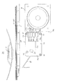
続いて、切断部材190の作用について概要説明する。上球皿30に貯留された遊技球
の中に糸付球Bが存在すると、当該糸付球Bは他の遊技球(正当な遊技球)とともに
上球皿30から球送りダクト35を通って球供給通路136を流下し、球送り機構140
により1球ずつ発射レール158の発射位置に送出され、発射機構150のハンマー15
1により遊技領域PAに向けて打ち出される。このとき、糸付球Bに固着された糸状体
Iは、球供給通路136から発射レール158に通された状態で、不正行為者によって引
っ張れると、発射機構150のハンマー151による打撃の勢いにより真っ直ぐ伸びよう
とする張力が生じる。このとき、発射ユニット100内の球通路において、球送り機構1
40の球通路(球導出路138)と発射機構150の球通路(発射レール158)とにお
ける当該通路方向が切り替わる方向転換部に、すなわち、球出口139の近傍に開放端1
92を打球位置側に向けて切断部材190が設けられているため、発射機構150により
打ち出された糸付球Bに繋がる糸状体Iは、切断部材190の開放端192から進入し
、谷部193を形成する斜辺192aのいずれかに当接して谷部193の底部193aに
導かれる。そして、糸状体Iは、この谷部193から連続して形成されたV字溝195内
に入り込み、その動作を規制されつつ刃部195aに接触して切断される。
Next, the operation of the cutting member 190 will be outlined. When Itozuke ball B I in the game ball that is stored in the upper ball tray 30 is present, the ball feed duct 35 from the upper ball pan 30 the yarn with balls B I other game ball (legitimate game balls) with Through the ball supply passage 136 and the ball feed mechanism 140.
Is sent to the launch position of the launch rail 158 one by one by the hammer 15 of the launch mechanism 150.
1 is launched toward the game area PA. At this time, if the filament I fixed to the threaded ball BI is pulled by an unauthorized person while being passed from the ball supply passage 136 to the firing rail 158, the hammer 151 of the firing mechanism 150 causes the impact. A tension is generated to stretch straight. At this time, in the ball passage in the launch unit 100, the ball feed mechanism 1
The open end 1 is located at a direction changing portion where the passage direction is switched between the 40 ball passages (ball outlet passage 138) and the ball passage (fire rail 158) of the launch mechanism 150, that is, near the ball outlet 139.
For 92 cutting member 190 toward the hitting position side is provided, filament I lead to thread with balls B I was struck by the firing mechanism 150, enters from the open end 192 of the cutting member 190, valleys It contacts any one of the oblique sides 192 a forming 193 and is guided to the bottom 193 a of the valley 193. The filament I enters the V-shaped groove 195 formed continuously from the valley 193, and is cut while contacting the blade 195a while restricting its operation.

従って、不正行為者が操作する糸状体Iを容易に切断部材190に接触させて切断する
ことができるため、糸付球Bを不正に操作して遊技球の入賞を検出させる不正入賞行為
を効果的に抑止することが可能である。
Thus, illegal because actors can be cut in contact with the easily cut member 190 filaments I manipulate, fraudulent winning act of detecting a winning of game ball thread with balls B I was rigged It can be effectively deterred.

以上説明した本実施形態において達成される主要な効果を整理すれば、下記のようにな
る。
The main effects achieved in the present embodiment described above are summarized as follows.

第1に、前枠2の遊技補助盤25には、発射ユニット100が当該遊技補助盤25に固
定ネジ101によってネジ止め固定されたときに、パチンコ機PM正面(前方)から見て
発射ユニット100によって隠蔽される位置に発射制御基板160と払出制御基板47と
を電気接続するハーネス173を通過させるハーネス通過口252が形成されている。従
って、発射ユニット100の正面側から見てハーネス173をほとんど露出させずにハー
ネス通過口252から前枠2の裏面側に引き回すことができるため、パチンコ機PMの正
面側からハーネス173に対してアクセスすることは非常に困難となる。そのため、ハー
ネス173を引張ることで基板側コネクタ163Cからハーネス側コネクタ173Cを引
き抜くのを困難にでき、発射制御基板160およびハーネス173に対する不正行為を効
果的に防止することが可能である。
First, when the launch unit 100 is fixed to the game assisting board 25 of the front frame 2 by a fixing screw 101, the launching unit 100 is viewed from the front (front) of the pachinko machine PM. A harness passage opening 252 through which the harness 173 that electrically connects the launch control board 160 and the payout control board 47 is passed is formed at a position hidden by. Accordingly, the harness 173 can be drawn from the harness passage port 252 to the back side of the front frame 2 without exposing the harness 173 when viewed from the front side of the launch unit 100, so that the harness 173 is accessed from the front side of the pachinko machine PM. It will be very difficult to do. Therefore, it is possible to make it difficult to pull out the harness side connector 173C from the board side connector 163C by pulling the harness 173, and it is possible to effectively prevent an illegal act on the launch control board 160 and the harness 173.

第2に、前枠2の前面側において発射ユニット100の近傍には、基板側コネクタ16
3Cに対するハーネス側コネクタ173Cの抜脱を規制するスピーカ26が近接して配置
されているため、発射ユニット100を前枠2の遊技補助盤25から取り外すことなく基
板側コネクタ163Cからハーネス側コネクタ173Cを引き抜くことを困難にでき、発
射制御基板160に対する不正行為を効果的に防止することが可能である。
Second, on the front side of the front frame 2, there is a board-side connector 16 near the launch unit 100.
Since the speaker 26 that restricts the removal of the harness side connector 173C with respect to 3C is disposed in the vicinity, the harness side connector 173C is removed from the board side connector 163C without removing the firing unit 100 from the game auxiliary board 25 of the front frame 2. It is possible to make it difficult to pull out, and it is possible to effectively prevent illegal acts on the launch control board 160.

第3に、ユニットケース110の前面と上球皿30(球送りダクト35)の後面とは所
定の間隔C1を有して離間しており、この間隔C1は上球皿6が前枠2の遊技補助盤25
を閉止する閉止位置にあるとき、ケース本体部材120に対するケース蓋部材130の開
放を阻止する大きさ(ここでの大きさは「距離」である)に形成されている。従って、発
射ユニット100のユニットケース110を開放させようとしても、ケース本体部材12
0に対するケース蓋部材130の相対移動は上球皿30の背面(球送りダクト35)によ
って規制されるので、上球皿6を遊技補助盤25(前枠2)に対して開放させることなく
、発射ユニット100のユニットケース110を開放させることを困難にでき、発射ユニ
ット100(主として、発射制御基板160)に対する不正行為を効果的に防止すること
が可能である。また、外的要因による発射ユニット100の破損を防止することができる
Thirdly, the front surface of the unit case 110 and the rear surface of the upper ball tray 30 (ball feed duct 35) are spaced apart from each other with a predetermined interval C1. Game auxiliary board 25
Is in a size that prevents the case body member 120 from being opened with respect to the case body member 120 (the size here is “distance”). Therefore, even if the unit case 110 of the launch unit 100 is to be opened, the case body member 12
Since the relative movement of the case lid member 130 with respect to 0 is restricted by the back surface (ball feed duct 35) of the upper ball tray 30, without opening the upper ball tray 6 with respect to the game auxiliary board 25 (front frame 2), It is possible to make it difficult to open the unit case 110 of the launch unit 100, and it is possible to effectively prevent illegal acts on the launch unit 100 (mainly the launch control board 160). Further, it is possible to prevent the launch unit 100 from being damaged due to external factors.

第4に、発射機構150はケース本体部材120に取り付けられ、払出制御基板160
は相手方のケース蓋部材130に発射機構150の作動により発生する振動を吸収可能な
防振部材180を介在させて取り付けられている。従って、発射制御基板160は防振部
材180を介してケース蓋部材130に取り付けられることになり、ケース本体部材12
0とケース蓋部材130とが結合状態において発射機構150の作動時に発生する振動が
防振部材180により吸収されて発射制御基板160に伝達するのが防止される。
Fourth, the firing mechanism 150 is attached to the case main body member 120 and the dispensing control board 160.
Is attached to the counterpart case lid member 130 with a vibration isolating member 180 capable of absorbing vibration generated by the operation of the firing mechanism 150 interposed therebetween. Accordingly, the launch control board 160 is attached to the case lid member 130 via the vibration isolation member 180, and the case main body member 12.
The vibration generated when the firing mechanism 150 is operated in a state where 0 and the case lid member 130 are coupled to each other is prevented from being absorbed by the vibration isolation member 180 and transmitted to the firing control board 160.

第5に、球送り機構140に形成されて当該球送り機構140から発射機構150へ遊
技球を送出する球導出路(第1球通路)138と、発射機構150に形成されて発射口1
11に向かって延出する発射レール(第2球通路)158と、における当該通路方向が切
り替わる方向転換部の近傍に、すなわち、球出口139の近傍に球通路138,158に
通された糸状体を受容して切断可能な切断部材190が設けられているため、不正行為者
により引っ張られて、あるいは発射機構150のハンマーによる打撃の勢いにより真っ直
ぐ伸びようとする(張力が生じる)糸状体Iを、容易に切断部材190に接触させて切断
することができる。従って、釣糸等の糸状体Iを付けた遊技球を不正に操作して遊技球の
入賞を検出させる不正入賞行為を効果的に抑止することが可能である。
Fifth, a ball lead-out path (first ball passage) 138 that is formed in the ball feeding mechanism 140 and sends a game ball from the ball feeding mechanism 140 to the launching mechanism 150, and a launching port 1 that is formed in the launching mechanism 150.
11 and the filaments passed through the ball passages 138 and 158 in the vicinity of the direction change portion where the passage direction is switched in the launch rail (second ball passage) 158 extending toward 11, that is, in the vicinity of the ball outlet 139. Since the cutting member 190 capable of receiving and cutting is provided, the filament I that tends to be stretched (tension is generated) by being pulled by an unauthorized person or by the momentum of striking by the hammer of the firing mechanism 150. The cutting member 190 can be easily brought into contact with and cut. Accordingly, it is possible to effectively prevent an illegal winning action that illegally operates a game ball with a filament I such as a fishing line to detect a winning of the game ball.

なお、本発明は、上記実施形態に限定されるものではなく、本発明の要旨を逸脱しない
範囲であれば適宜改良可能である。
In addition, this invention is not limited to the said embodiment, If it is a range which does not deviate from the summary of this invention, it can improve suitably.

上述の実施形態では、前枠2の前面側において発射ユニット100の近傍に、基板側コ
ネクタ163Cに対するハーネス側コネクタ173Cの抜脱を規制するための規制手段と
して、スピーカ26の側壁26aを適用した場合を例示して説明したが、これに限定され
るものではなく、例えば、発射ハンドルから空気を送り出すための送風機などの他のユニ
ットの側壁を適用したり、前枠2に一体形成された壁部を規制手段として適用してもよい
In the above-described embodiment, when the side wall 26a of the speaker 26 is applied in the vicinity of the launch unit 100 on the front side of the front frame 2 as a restricting means for restricting the removal of the harness-side connector 173C from the board-side connector 163C. However, the present invention is not limited to this. For example, the side wall of another unit such as a blower for sending air from the launch handle or the wall portion integrally formed with the front frame 2 is used. May be applied as a regulating means.

上述の実施形態では、ケース本体部材120に対するケース蓋部材130の開放を阻止
するように、ケース蓋部材130の前面側に当接する上球皿30の阻止部材として、上球
皿30に貯留する遊技球を発射ユニット100に導く球送りダクト35に適用した場合を
説明したが、これに限定されるものではなく、上球皿30の背面から後方に突出する突起
部を形成してもよい。また、上球皿30の当て板31自体、すなわち当て板31の背面(
フラット面)をケース蓋部材130の開放を阻止する阻止部材として適用してもよい。ま
た、当て板31の背面はフラット面である必要はなく、発射ユニットの前端形状に合わせ
て所定の間隔が形成されるような凹凸形状にしてもよい。
In the above-described embodiment, a game stored in the upper ball tray 30 as a blocking member of the upper ball tray 30 that contacts the front side of the case lid member 130 so as to prevent the case main body member 120 from opening the case lid member 130. Although the case where it applied to the ball | bowl feed duct 35 which guide | induces a ball | bowl to the launch unit 100 was demonstrated, it is not limited to this, You may form the projection part which protrudes back from the back surface of the upper ball tray 30. FIG. Further, the backing plate 31 itself of the upper ball tray 30, that is, the back surface of the backing plate 31 (
The flat surface may be applied as a blocking member that prevents the case lid member 130 from being opened. Moreover, the back surface of the contact plate 31 does not need to be a flat surface, and may be an uneven shape in which a predetermined interval is formed in accordance with the front end shape of the firing unit.

また、上述の実施形態では、発射制御基板160を発射ユニット100内に収容保持さ
れる基板として構成した場合を例示して説明したが、これに限定されるものではなく、発
射制御基板を第2裏セット盤45に配設して、この発射制御基板と発射ソレノイド等との
間で電気接続される中継基板を発射ユニット内に収容保持される基板として構成してもよ
い。
In the above-described embodiment, the case where the launch control board 160 is configured as a board that is accommodated and held in the launch unit 100 has been described as an example. However, the present invention is not limited to this, and the launch control board is the second. A relay board that is disposed on the back set board 45 and is electrically connected between the launch control board and the launch solenoid may be configured as a board that is housed and held in the launch unit.

また、上述の実施形態では、ケース本体部材120に発射機構150を備え、ケース蓋
部材130に球送り機構140および発射制御基板160を備えた構成を例示して説明し
たが、これに限定されるものではなく、発射機構、球送り機構および発射制御基板を適宜
に配置してよい。
In the above-described embodiment, the case body member 120 includes the launch mechanism 150 and the case lid member 130 includes the ball feed mechanism 140 and the launch control board 160. However, the configuration is limited to this. The firing mechanism, the ball feeding mechanism, and the launch control board may be appropriately arranged instead of the ones.

また、上述の実施形態では、発射制御基板160に実装された基板側コネクタ163c
〜166cはユニットケース110のケース開口134から外方に露出しているが、これ
に限定されるものではなく、基板側コネクタをユニットケース内に収容された状態で取り
付けて、相手方のハーネス側コネクタをユニットケースのケース開口からケース内に挿入
して基板側コネクタと嵌合および抜去可能に構成してもよい。
In the above-described embodiment, the board-side connector 163c mounted on the launch control board 160
˜166c is exposed to the outside from the case opening 134 of the unit case 110, but is not limited to this, and the board side connector is attached while being accommodated in the unit case, and the other side harness side connector is attached. May be inserted into the case from the case opening of the unit case so as to be able to be fitted to and removed from the board-side connector.

また、上述の実施形態では、発射制御基板160はケース蓋部材130に固定されてユ
ニットケース110内に収容されているが、これに限定されるものではなく、例えば、発
射制御基板全体をユニットケースの外面に露出した状態で取り付けて構成してもよい。
In the above-described embodiment, the launch control board 160 is fixed to the case lid member 130 and accommodated in the unit case 110. However, the present invention is not limited to this. You may attach and comprise in the state exposed to the outer surface.

また、上述の実施形態では、発射ユニット100は4本のネジボス251を介して前枠
2から前方に浮いた状態で取り付けられ、ユニットケース110の後面と前枠2の前面と
の間の空いたスペースに発射ソレノイド154を収容するように構成されているが、これ
に限定されるものではなく、前枠に発射ソレノイドを収容可能な収容空間(例えば、貫通
孔又は凹部)を形成して、ユニットケースの後面と前枠の前面とがほぼ面一の状態で、発
射ユニットを前枠に取り付け可能に構成してもよい。なお、このときハーネスを前枠に挿
通させるハーネス通過口は、上記収容空間と一体的に形成してもよいし、上記収容空間と
は独立して形成してもよく、例えば、ハーネス通過口をユニットケースの後面の周縁部と
前枠2の前面とが当接しない部分に形成することで、ハーネスをユニットケースの後面側
に引き回してハーネス通過口を通すことができる。
Further, in the above-described embodiment, the launch unit 100 is attached in a state of floating forward from the front frame 2 via the four screw bosses 251, so that there is a space between the rear surface of the unit case 110 and the front surface of the front frame 2. The launch solenoid 154 is configured to be accommodated in the space. However, the present invention is not limited to this, and a unit space (for example, a through hole or a recess) in which the launch solenoid can be accommodated in the front frame is formed. The launch unit may be configured to be attachable to the front frame while the rear surface of the case and the front surface of the front frame are substantially flush with each other. At this time, the harness passage port through which the harness is inserted into the front frame may be formed integrally with the housing space, or may be formed independently of the housing space. By forming in the part where the peripheral part of the rear surface of a unit case and the front surface of the front frame 2 do not contact | abut, a harness can be drawn around the rear surface side of a unit case, and a harness passage opening can be let through.

また、上述の実施形態では、ガラス枠5と上球皿30とが別体として構成され、それぞ
れが前枠2に対して独立して横開き開閉可能な構成を例示して説明したが、これに限定さ
れるものではなく、ガラス枠に球皿(上球皿および下球皿又は一体皿)を一体的に形成し
て構成してもよく、この場合にはガラス枠が請求の範囲に規定する開閉部材に相当するこ
とになる。
Further, in the above-described embodiment, the glass frame 5 and the upper ball tray 30 are configured as separate bodies, and each has been described by exemplifying a configuration that can be opened and closed independently with respect to the front frame 2. However, the glass frame may be formed by integrally forming a ball tray (an upper ball tray and a lower ball tray or an integral plate). In this case, the glass frame is defined in the claims. This corresponds to the opening / closing member to be operated.

また、上述の実施形態では、発射制御基板160とケース蓋部材130との取付部に防
振部材180を装着しているが、これに限定されるものではなく、ケース本体部材120
とケース蓋部材130との取付部に防振部材を装着する構成であっても、発射機構作動時
の振動が発射制御基板に伝達されるのを抑止することができる。
In the above-described embodiment, the vibration isolation member 180 is attached to the attachment portion between the launch control board 160 and the case lid member 130. However, the present invention is not limited to this, and the case body member 120 is not limited thereto.
Even when the vibration isolating member is attached to the attachment portion between the case lid member 130 and the case lid member 130, it is possible to prevent the vibration during the activation of the firing mechanism from being transmitted to the firing control board.

また、糸状体を切断する切断部材としては本実施形態で例示した切断部材180の形状
に限定されず、釣り糸等の糸状体を切断し得るものであれば、切れ刃を有するカッターや
、ヤスリ等の研磨具などの一般的な工具を利用してもよい。
Further, the cutting member for cutting the filamentous body is not limited to the shape of the cutting member 180 exemplified in the present embodiment, and a cutter having a cutting blade, a file, etc., as long as it can cut the filamentous body such as fishing line, etc. A general tool such as a polishing tool may be used.

また、上述の実施形態では、発射機構150のハンマー作動手段としてロータリソレノ
イド154が適用されているが、これに限定されるものではなく、パルスモータやサーボ
モータ、ACモータ、DCモータ等の電動アクチュエータを利用するものであってもよい
Further, in the above-described embodiment, the rotary solenoid 154 is applied as the hammer actuating means of the firing mechanism 150. However, the present invention is not limited to this, and an electric actuator such as a pulse motor, a servo motor, an AC motor, or a DC motor is used. May be used.

また、上述の実施形態では、本発明を上球皿30と下球皿7とを有する球皿別体型のパ
チンコ機PMに適用した場合を例示して説明したが、これに限定されるものではなく、単
一の球皿のみを有する球皿一体型のパチンコ機に適用してもよい。
Further, in the above-described embodiment, the case where the present invention is applied to the pachinko machine PM having a separate ball dish having the upper ball dish 30 and the lower ball dish 7 has been described as an example, but the present invention is not limited thereto. Alternatively, the present invention may be applied to a ball-plate-integrated pachinko machine having only a single ball plate.

なお、上述の実施形態では、本発明をパチンコ機に適用した事例について説明したが、
アレンジボール機や雀球遊技機などの他の遊技機に適用することができ、同様の効果を得
ることができる。
In the above-described embodiment, an example in which the present invention is applied to a pachinko machine has been described.
It can be applied to other gaming machines such as an arrangement ball machine and a sparrow ball game machine, and the same effect can be obtained.

PM パチンコ機(弾球遊技機)
PA 遊技領域
I 糸状体
1 外枠
2 前枠(枠部材)
5 ガラス枠
8 発射ハンドル
10 遊技盤
18 メイン制御基板
19 サブ制御基板
25 遊技補助盤
26 スピーカ
30 上球皿(開閉部材)
32 球皿部
35 球送りダクト
47 払出制御基板(第1基板)
100 発射ユニット
110 ユニットケース(ケース部材)
111 発射口
120 ケース本体部材(第1ケース部材)
130 ケース蓋部材(第2ケース部材)
134 ケース開口
138 球導出路
140 球送り機構
145 球送りソレノイド
150 発射機構
154 発射ソレノイド
158 発射レール
160 発射制御基板(第2基板)
163C 基板側コネクタ
173 ハーネス
173C ハーネス側コネクタ
180 防振部材
190 切断部材
252 ハーネス通過口
PM Pachinko machine (ball game machine)
PA gaming area I filament 1 outer frame 2 front frame (frame member)
5 Glass frame 8 Launch handle 10 Game board 18 Main control board 19 Sub control board 25 Game auxiliary board 26 Speaker 30 Upper ball tray (opening / closing member)
32 Ball tray 35 Ball feed duct 47 Dispensing control board (first board)
100 launch unit 110 unit case (case member)
111 Launch Port 120 Case Body Member (First Case Member)
130 Case lid member (second case member)
134 Case opening 138 Ball lead-out path 140 Ball feed mechanism 145 Ball feed solenoid 150 Launch mechanism 154 Launch solenoid 158 Launch rail 160 Launch control board (second board)
163C Board side connector 173 Harness 173C Harness side connector 180 Anti-vibration member 190 Cutting member 252 Harness passage port

Claims (1)

前面側に所定の遊技領域が形成された遊技盤を保持する枠部材と、
前記枠部材の前面側に開閉自在に設けられ、前記枠部材の少なくとも一部を覆う閉止位置と、当該一部を開放する開放位置との間で揺動する開閉部材と、
前記枠部材の前面側に設けられて、遊技球を前記遊技領域に向けて打ち出す発射ユニットと、を備える弾球遊技機であって、
前記発射ユニットは、
ソレノイドの駆動により球送り部材を動作させて遊技球を球送りする球送り機構と、
前記球送り機構から球送りされた遊技球を発射レールに沿って前記遊技領域へ向けて打ち出す発射機構と、
前記発射機構の側に設けられるケース本体と当該ケース本体に開閉可能に取り付けられて前記球送り機構の側に設けられるケース蓋とを有するケース部材と、を備えて構成され、
前記発射レールに近接して、前記球送り機構から前記発射機構へ通された糸状体を受容して切断可能な切断部材が設けられ、前記切断部材の主面の少なくとも一部が遊技球の発射軌道に対して略平行となるよう配置され、
前記切断部材が前記ケース蓋によって前面側から覆われた状態で前記ケース蓋に設けられ、前記切断部材は遊技球の発射方向から見て前記球送り機構と前記発射機構との間に配置されており、
前記切断部材は、前記ケース蓋に一つ設けられ、薄板状に形成された本体部と、前記本体部に凹設されて前記糸状体を受容する一つの谷部とを有することを特徴とする弾球遊技機。
A frame member for holding a game board in which a predetermined game area is formed on the front side;
An opening / closing member provided on the front side of the frame member so as to be freely openable and closable between a closed position that covers at least a part of the frame member and an open position that opens the part;
A launching unit provided on the front side of the frame member and launching a game ball toward the game area,
The launch unit is
A ball feed mechanism that moves the ball by moving the ball feed member by driving the solenoid;
A launch mechanism that launches a game ball fed from the ball feed mechanism toward the game area along a launch rail;
A case body having a case main body provided on the launching mechanism side and a case lid attached to the case main body so as to be openable and closable and provided on the ball feeding mechanism side; and
A cutting member capable of receiving and cutting the filament passed from the ball feeding mechanism to the firing mechanism is provided in the vicinity of the firing rail, and at least a part of the main surface of the cutting member launches a game ball. Arranged so as to be substantially parallel to the orbit,
The cutting member is provided on the case lid in a state of being covered from the front side by the case lid, and the cutting member is disposed between the ball feeding mechanism and the launching mechanism as viewed from the launch direction of the game ball. And
One of the cutting members is provided on the case lid, and has a main body portion formed in a thin plate shape, and one trough portion that is recessed in the main body portion and receives the filamentous body. A ball game machine.
JP2014205507A 2014-10-06 2014-10-06 Bullet ball machine Active JP5907542B2 (en)

Priority Applications (1)

Application Number Priority Date Filing Date Title
JP2014205507A JP5907542B2 (en) 2014-10-06 2014-10-06 Bullet ball machine

Applications Claiming Priority (1)

Application Number Priority Date Filing Date Title
JP2014205507A JP5907542B2 (en) 2014-10-06 2014-10-06 Bullet ball machine

Related Parent Applications (1)

Application Number Title Priority Date Filing Date
JP2011234048A Division JP2013090734A (en) 2011-10-25 2011-10-25 Pachinko game machine

Related Child Applications (1)

Application Number Title Priority Date Filing Date
JP2016052549A Division JP6185105B2 (en) 2016-03-16 2016-03-16 Bullet ball machine

Publications (3)

Publication Number Publication Date
JP2015006538A JP2015006538A (en) 2015-01-15
JP2015006538A5 JP2015006538A5 (en) 2015-09-03
JP5907542B2 true JP5907542B2 (en) 2016-04-26

Family

ID=52337288

Family Applications (1)

Application Number Title Priority Date Filing Date
JP2014205507A Active JP5907542B2 (en) 2014-10-06 2014-10-06 Bullet ball machine

Country Status (1)

Country Link
JP (1) JP5907542B2 (en)

Cited By (1)

* Cited by examiner, † Cited by third party
Publication number Priority date Publication date Assignee Title
JP2016105910A (en) * 2016-03-16 2016-06-16 サミー株式会社 Pinball game machine

Family Cites Families (2)

* Cited by examiner, † Cited by third party
Publication number Priority date Publication date Assignee Title
JP5158220B2 (en) * 2011-02-22 2013-03-06 タイヨーエレック株式会社 Game machine
JP5285728B2 (en) * 2011-02-28 2013-09-11 株式会社サンセイアールアンドディ Bullet ball machine

Cited By (1)

* Cited by examiner, † Cited by third party
Publication number Priority date Publication date Assignee Title
JP2016105910A (en) * 2016-03-16 2016-06-16 サミー株式会社 Pinball game machine

Also Published As

Publication number Publication date
JP2015006538A (en) 2015-01-15

Similar Documents

Publication Publication Date Title
JP2013090734A (en) Pachinko game machine
JP5669267B2 (en) Bullet ball machine
JP6112742B2 (en) Bullet ball machine
JP2012050767A (en) Ball return prevention device of pinball game machine
JP2012050768A (en) Ball-return prevention device of pinball game machine
JP5773363B2 (en) Bullet ball machine
JP6185105B2 (en) Bullet ball machine
JP5641543B2 (en) Bullet ball machine
JP5907542B2 (en) Bullet ball machine
JP5669269B2 (en) Bullet ball machine
JP6200987B2 (en) Bullet ball machine
JP5904611B2 (en) Bullet ball machine
JP6090883B2 (en) Bullet ball machine
JP6200986B2 (en) Bullet ball machine
JP5871248B2 (en) Bullet ball machine
JP5669268B2 (en) Bullet ball machine
JP2015044115A (en) Pachinko game machine
JP2015044116A (en) Pinball game machine
JP2016073733A (en) Pinball game machine
JP6454979B2 (en) Bullet ball machine
JP2018011715A (en) Pinball game machine
JP5813084B2 (en) Bullet ball machine
JP2006141501A (en) Flow straightener of pinball game machine
JP2015202194A (en) Pinball game machine
JP5901049B2 (en) Bullet ball machine

Legal Events

Date Code Title Description
A621 Written request for application examination

Free format text: JAPANESE INTERMEDIATE CODE: A621

Effective date: 20141104

A521 Request for written amendment filed

Free format text: JAPANESE INTERMEDIATE CODE: A523

Effective date: 20150716

A977 Report on retrieval

Free format text: JAPANESE INTERMEDIATE CODE: A971007

Effective date: 20151120

A131 Notification of reasons for refusal

Free format text: JAPANESE INTERMEDIATE CODE: A131

Effective date: 20151201

A521 Request for written amendment filed

Free format text: JAPANESE INTERMEDIATE CODE: A523

Effective date: 20160129

TRDD Decision of grant or rejection written
A01 Written decision to grant a patent or to grant a registration (utility model)

Free format text: JAPANESE INTERMEDIATE CODE: A01

Effective date: 20160223

A61 First payment of annual fees (during grant procedure)

Free format text: JAPANESE INTERMEDIATE CODE: A61

Effective date: 20160316

R150 Certificate of patent or registration of utility model

Ref document number: 5907542

Country of ref document: JP

Free format text: JAPANESE INTERMEDIATE CODE: R150

S531 Written request for registration of change of domicile

Free format text: JAPANESE INTERMEDIATE CODE: R313531

R350 Written notification of registration of transfer

Free format text: JAPANESE INTERMEDIATE CODE: R350

R250 Receipt of annual fees

Free format text: JAPANESE INTERMEDIATE CODE: R250

R250 Receipt of annual fees

Free format text: JAPANESE INTERMEDIATE CODE: R250

R250 Receipt of annual fees

Free format text: JAPANESE INTERMEDIATE CODE: R250

R250 Receipt of annual fees

Free format text: JAPANESE INTERMEDIATE CODE: R250

R250 Receipt of annual fees

Free format text: JAPANESE INTERMEDIATE CODE: R250

R250 Receipt of annual fees

Free format text: JAPANESE INTERMEDIATE CODE: R250