JP6108940B2 - Image blur correction apparatus, control method therefor, program, and storage medium - Google Patents
Image blur correction apparatus, control method therefor, program, and storage medium Download PDFInfo
- Publication number
- JP6108940B2 JP6108940B2 JP2013093044A JP2013093044A JP6108940B2 JP 6108940 B2 JP6108940 B2 JP 6108940B2 JP 2013093044 A JP2013093044 A JP 2013093044A JP 2013093044 A JP2013093044 A JP 2013093044A JP 6108940 B2 JP6108940 B2 JP 6108940B2
- Authority
- JP
- Japan
- Prior art keywords
- speed
- panning
- shake
- detection
- image blur
- Prior art date
- Legal status (The legal status is an assumption and is not a legal conclusion. Google has not performed a legal analysis and makes no representation as to the accuracy of the status listed.)
- Active
Links
Images


Classifications
-
- H—ELECTRICITY
- H04—ELECTRIC COMMUNICATION TECHNIQUE
- H04N—PICTORIAL COMMUNICATION, e.g. TELEVISION
- H04N23/00—Cameras or camera modules comprising electronic image sensors; Control thereof
- H04N23/60—Control of cameras or camera modules
- H04N23/68—Control of cameras or camera modules for stable pick-up of the scene, e.g. compensating for camera body vibrations
- H04N23/682—Vibration or motion blur correction
-
- H—ELECTRICITY
- H04—ELECTRIC COMMUNICATION TECHNIQUE
- H04N—PICTORIAL COMMUNICATION, e.g. TELEVISION
- H04N23/00—Cameras or camera modules comprising electronic image sensors; Control thereof
- H04N23/60—Control of cameras or camera modules
- H04N23/68—Control of cameras or camera modules for stable pick-up of the scene, e.g. compensating for camera body vibrations
- H04N23/681—Motion detection
- H04N23/6815—Motion detection by distinguishing pan or tilt from motion
-
- G—PHYSICS
- G02—OPTICS
- G02B—OPTICAL ELEMENTS, SYSTEMS OR APPARATUS
- G02B27/00—Optical systems or apparatus not provided for by any of the groups G02B1/00 - G02B26/00, G02B30/00
- G02B27/64—Imaging systems using optical elements for stabilisation of the lateral and angular position of the image
- G02B27/646—Imaging systems using optical elements for stabilisation of the lateral and angular position of the image compensating for small deviations, e.g. due to vibration or shake
-
- H—ELECTRICITY
- H04—ELECTRIC COMMUNICATION TECHNIQUE
- H04N—PICTORIAL COMMUNICATION, e.g. TELEVISION
- H04N23/00—Cameras or camera modules comprising electronic image sensors; Control thereof
- H04N23/60—Control of cameras or camera modules
- H04N23/68—Control of cameras or camera modules for stable pick-up of the scene, e.g. compensating for camera body vibrations
- H04N23/681—Motion detection
- H04N23/6812—Motion detection based on additional sensors, e.g. acceleration sensors
-
- H—ELECTRICITY
- H04—ELECTRIC COMMUNICATION TECHNIQUE
- H04N—PICTORIAL COMMUNICATION, e.g. TELEVISION
- H04N23/00—Cameras or camera modules comprising electronic image sensors; Control thereof
- H04N23/60—Control of cameras or camera modules
- H04N23/68—Control of cameras or camera modules for stable pick-up of the scene, e.g. compensating for camera body vibrations
- H04N23/682—Vibration or motion blur correction
- H04N23/685—Vibration or motion blur correction performed by mechanical compensation
- H04N23/687—Vibration or motion blur correction performed by mechanical compensation by shifting the lens or sensor position
-
- G—PHYSICS
- G03—PHOTOGRAPHY; CINEMATOGRAPHY; ANALOGOUS TECHNIQUES USING WAVES OTHER THAN OPTICAL WAVES; ELECTROGRAPHY; HOLOGRAPHY
- G03B—APPARATUS OR ARRANGEMENTS FOR TAKING PHOTOGRAPHS OR FOR PROJECTING OR VIEWING THEM; APPARATUS OR ARRANGEMENTS EMPLOYING ANALOGOUS TECHNIQUES USING WAVES OTHER THAN OPTICAL WAVES; ACCESSORIES THEREFOR
- G03B2205/00—Adjustment of optical system relative to image or object surface other than for focusing
- G03B2205/0007—Movement of one or more optical elements for control of motion blur
Description
本発明は、パンニング動作を考慮した像振れ補正を行うことで、一定速に近い滑らかなパンニングを実現する技術に関するものである。 The present invention relates to a technique for realizing smooth panning close to a constant speed by performing image blur correction in consideration of a panning operation.
動画撮影において、滑らかなパンニング動作は、常に要求されるカメラワークの一つである。しかし、手持ち撮影の場合、あるいは三脚設置状態でも手動でパンニングを行った場合には、手の動きを一定の速度で動かすことは不可能であり、滑らかで一定速に近いパンニングを行うことは非常に困難であった。 In moving image shooting, a smooth panning operation is one of the always required camera works. However, in the case of hand-held shooting, or when panning is performed manually even with a tripod installed, it is impossible to move the hand at a constant speed, and it is extremely difficult to perform panning that is smooth and close to a constant speed. It was difficult.
近年、ビデオカメラなどの動画像を撮影する撮像装置において、手振れに起因する像振れの補正は必須の機能となっている。パンニング動作に関連した像振れ補正技術についても、パンニング方向に対して垂直な方向の像振れを補正する方法など、多く提案されている(例えば、特許文献1参照)。 In recent years, correction of image blur due to camera shake has become an indispensable function in an imaging apparatus such as a video camera that captures a moving image. Many image blur correction techniques related to the panning operation have been proposed, such as a method for correcting image blur in a direction perpendicular to the panning direction (see, for example, Patent Document 1).
しかしながら、上記の従来技術における像振れ補正方法では、パンニング方向に対して垂直な方向の像振れを補正することはできるが、パンニング方向と同方向(水平な方向)の像振れは補正できない。従って、撮影者のパンニング操作に対して、滑らかで一定速に近いパンニング動作を実現することが困難であるという問題があった。 However, with the above-described image blur correction method in the prior art, image blur in a direction perpendicular to the panning direction can be corrected, but image blur in the same direction (horizontal direction) as the panning direction cannot be corrected. Accordingly, there is a problem that it is difficult to realize a smooth panning operation at a constant speed with respect to the panning operation of the photographer.
本発明は、上述した課題に鑑みてなされたものであり、その目的は、像振れ補正を行いつつも、一定速に近い滑らかなパンニング動作を実現することである。 The present invention has been made in view of the above-described problems, and an object thereof is to realize a smooth panning operation close to a constant speed while performing image blur correction.
本発明に係わる像振れ補正装置は、装置の振れを検出する振れ検出手段と、撮影画像の振れを補正する像振れ補正手段と、前記振れ検出手段の検出結果に基づいて、パンニング動作が実行されているか否かを検出するパンニング検出手段と、前記パンニング動作の目標速度を設定する速度設定手段と、前記速度設定手段で設定した目標速度と前記振れ検出手段で検出した振れの速度に基づいて前記像振れ補正手段の補正量を算出する算出手段と、前記パンニング検出手段により、前記パンニング動作が実行されていることが検出された場合に、前記算出手段で算出した補正量に基づいて前記像振れ補正手段の動きを制御する制御手段と、事前の操作に基づいて前記パンニング動作の目標速度を算出し、予め記憶手段に初期速度として記憶させる初期速度設定手段と、を備え、前記速度設定手段は、前記パンニング検出手段により前記パンニング動作が実行されていることを検出した直後は、前記初期速度設定手段により前記記憶手段に記憶させた前記初期速度を前記パンニング動作の目標速度として設定することを特徴とする。 An image shake correction apparatus according to the present invention performs a panning operation based on a shake detection unit that detects a shake of the apparatus, an image shake correction unit that corrects a shake of a captured image, and a detection result of the shake detection unit. Panning detection means for detecting whether or not the image is detected, speed setting means for setting a target speed of the panning operation, the target speed set by the speed setting means and the speed of shake detected by the shake detection means When the panning operation is detected by the calculating means for calculating the correction amount of the image blur correcting means and the panning detecting means, the image blur is calculated based on the correction amount calculated by the calculating means. and control means for controlling the movement of the correcting means, based on a pre-operation calculates a target speed of the panning operation, is stored as the initial speed in advance in the storage means With an initial speed setting means, wherein the speed setting means, immediately after detecting that the panning operation is being performed by the panning detecting means, the initial which is stored in the storage means by the initial speed setting means A speed is set as a target speed of the panning operation.
本発明によれば、像振れ補正を行いつつも、一定速に近い滑らかなパンニング動作を実現することが可能となる。 According to the present invention, it is possible to realize a smooth panning operation close to a constant speed while performing image blur correction.
以下、本発明の実施形態について、添付図面を参照しながら詳細に説明する。 Hereinafter, embodiments of the present invention will be described in detail with reference to the accompanying drawings.
(第1の実施形態)
図1は、本発明の第1の実施形態における撮像装置のシステム構成を示すブロック図である。図1において、変倍レンズ群1(ズームレンズ)は焦点距離を変えて変倍を行う。像振れ補正レンズ群2(シフトレンズ)は光軸と垂直な方向に動いて像振れ(撮影画像の振れ)を補正する。また、焦点調整レンズ群3(フォーカスレンズ)は焦点調節機能と変倍による焦点面の移動を補正するいわゆるコンペ機能を兼ね備えている。撮像素子4はレンズ群1,2,3を通して結像された被写体像を光電変換して画像信号を生成する。撮像素子4は、例えばCCDやCMOSセンサなどが用いられる。カメラ信号処理回路5は、アナログ信号処理回路とデジタル信号処理回路からなる。カメラ信号処理回路5のアナログ信号処理回路は撮像素子4で得られた信号に所定の処理を施してアナログ撮像信号を生成する回路である。そして、アナログ信号処理回路は、例えばCDS(co-related double sampling:相関二重サンプリング)回路、AGC(Automatic Gain Control)回路等から構成されている。カメラ信号処理回路5のデジタル信号処理回路は、A/D変換器によりアナログ撮像信号をデジタル信号に変換し、ガンマ補正処理、ホワイトバランス処理等、所定の信号処理を施したデジタル映像信号を生成する。
(First embodiment)
FIG. 1 is a block diagram showing a system configuration of the imaging apparatus according to the first embodiment of the present invention. In FIG. 1, a zoom lens group 1 (zoom lens) performs zooming by changing the focal length. The image blur correction lens group 2 (shift lens) moves in a direction perpendicular to the optical axis to correct image blur (camera image blur). The focus adjustment lens group 3 (focus lens) has both a focus adjustment function and a so-called competition function for correcting movement of the focal plane due to zooming. The
レコーダ部6は、記録媒体(メモリカード、ハードディスク、DVD、磁気テープなど)に映像信号を記録する記録装置、映像信号を出力表示する表示装置(液晶パネルやビューファインダなど)、及びそれらの制御回路などが含まれる。
The
また、像振れ補正機構の構成として、角速度検出器11,12は、例えば振動ジャイロセンサ等の角速度センサである。角速度検出器11及び12はそれぞれ異なった検出軸を持つ。本実施例においては、角速度検出器Y11はヨー方向(Yaw方向)の振れを検出し、角速度検出器P12はピッチ方向(Pitch方向)と振れを検出するものとする。増幅器(アンプ)13及び14は角速度検出器Y(Yaw方向)11,角速度検出器P(Pitch方向)12から出力された撮影時の撮像装置の振れを示す角速度信号を増幅して出力する。ハイパスフィルタ(HPF)15及び16は、カットオフ周波数を変更するなどして周波数特性を変更し得る機能を有しており、増幅器Y13及び増幅器P14にて増幅された角速度信号に含まれる低周波成分を遮断して出力する。積分器17及び18は、ハイパスフィルタ(HPF)15及び16から出力された角速度信号を積分することにより角変位量を得る。
Further, as a configuration of the image blur correction mechanism, the
移動検出部としてのパンニング検出部19は、積分器Y17から出力されるYaw方向の角変位量(角速度検出器11の検出結果)に基づいて、撮像装置の一定方向への画角移動動作であるパンニングの判定を行う。チルティング検出部20は、積分器18から出力されるPitch方向の角変位量に基づいてチルティングの判定を行う。パンニング速度設定部21は、Yaw方向のパンニング速度を設定する。また、パンニング速度設定部21は、角速度検出器11の出力結果からパンニング目標速度Vtを推定して設定する。また、パンニング速度設定部21は角変位量の時間変化から検出速度Vを算出する。さらに、パンニング速度設定部21は、検出速度Vとパンニング目標速度Vtとの差分から補正速度Vcを算出する。チルティング速度設定部22は、Pitch方向のチルティング速度を設定する。また、チルティング速度設定部22はパンニング速度設定部21と同様にパンニング目標速度Vtの推定、検出速度Vの算出、および補正速度Vcの算出を行う。Yaw方向の制御目標値生成部23は、積分器Y17から出力される角変位量とパンニング速度設定部21から出力されるパンニング速度とに基づいてシフトレンズ2の補正目標値を算出する。Pitch方向の制御目標値生成部24は、積分器P18から出力される角変位量とチルティング速度設定部22から出力されるチルティング速度とに基づいてシフトレンズ2の補正目標値を算出する。駆動部31,32は制御目標値生成部23及び24より得られた補正目標値に基づきシフトレンズ2を駆動するための駆動回路である。
The
次に、振れ検出から像振れ補正までの動作を説明する。まず、角速度検出器Y11及び角速度検出器P12によってカメラの振れが検出される。制御目標値生成部23,24は、検出された振れに対して、各軸ごとに角速度検出器Y11及び角速度検出器P12の各検出方向に一致する像振れ補正目標値を求める。駆動部31,32は、像振れ補正目標値信号に従ってYaw方向とPitch方向にシフトレンズ2を駆動制御する。これによって、光学的な像振れ補正が可能となる。
Next, operations from shake detection to image shake correction will be described. First, camera shake is detected by the angular velocity detector Y11 and the angular velocity detector P12. The control
ここで、角速度検出器Y11及び角速度検出器P12の検出軸を、レンズ群1,2,3の光軸に直交する一平面上で互いに直交した軸となるように配置する。これにより、カメラの左右方向の回転振れ(Yaw)およびカメラの上下方向の回転振れ(Pitch)を補正することができる。
Here, the detection axes of the angular velocity detector Y11 and the angular velocity detector P12 are arranged so as to be orthogonal to each other on one plane orthogonal to the optical axes of the
Yaw制御目標値生成回路23は、角速度検出器Y11の振れ信号に基づいてYaw方向の像振れ補正量を算出する。そして、Yaw駆動回路31は、角速度検出器Y11の検出軸方向と同一の補正軸方向にシフトレンズ2を駆動してYaw方向の像振れ補正を行う。。また同様に、Pitch制御目標値生成回路24は、角速度検出器P12の振れ信号に基づいてPitch方向の像振れ補正量を算出する。そして、Pitch駆動回路32は、角速度検出器P12の検出軸方向と同一の補正軸方向にシフトレンズ2を駆動してPitch方向の像振れ補正が行われる。
The Yaw control target
次に、カメラを水平方向に振るパンニング時の動作について説明する。なお、カメラを垂直方向に振るチルティングの動作については、カメラを振る方向が異なるだけで図1におけるYawとPitchの軸を入れ替えればパンニングと同様に処理できる。そのため、以下ではパンニング動作を例として説明し、チルティング動作についての説明は省略する。 Next, an operation at the time of panning in which the camera is shaken in the horizontal direction will be described. Note that the tilting operation in which the camera is shaken in the vertical direction can be processed in the same manner as panning if the Yaw and Pitch axes in FIG. Therefore, the panning operation will be described below as an example, and the description of the tilting operation will be omitted.
図2は、一定速度のパンニング動作を実現するための処理を示すフローチャートである。本フローは、所定の周期(例えば角速度センサの検出周期など)で繰り返し実行される。また、像振れ補正がONの時に限定しても良い。 FIG. 2 is a flowchart showing a process for realizing a panning operation at a constant speed. This flow is repeatedly executed at a predetermined cycle (for example, a detection cycle of an angular velocity sensor). Further, it may be limited when image blur correction is ON.
まず、ステップS1001においては、角速度検出器11は、振れの角速度を検出する。次にステップS1002において、積分器17は、振れの角速度を積分演算することによって角変位量を算出する。次にステップS1003において、パンニング速度設定部21は角変位量の時間変化から検出速度Vを算出する。次にステップS1004において、パンニング検出部19は、角変位量からパンニング判定を行う。ステップS1004においては、パンニング検出部19は、角変位量が同方向に変化しているか否かを判別すればよい。
First, in step S1001, the
ステップS1004で、パンニング検出部19によって装置がパンニング操作さていると判定された場合はステップ1005へ進み、パンニングでないと判断された場合はステップ1006へ進む。ステップ1005では、パンニング速度設定部21は、角速度検出器11の出力結果からパンニング目標速度Vtを推定して設定する。ステップ1006では、パンニング目標速度Vtを0と設定する。
In step S1004, if the panning
次にステップ1007では、パンニング速度設定部21は、ステップ1003で算出した検出速度Vとステップ1005(あるいはステップ1006)で設定したパンニング目標速度Vtとの差分から補正速度Vcを算出する。ステップ1008では、制御目標値生成部23は、ステップ1007で算出した補正速度Vcから補正目標位置を求め、シフトレンズを補正する。
Next, in step 1007, the panning
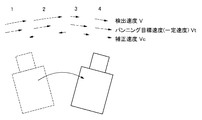
図3は、一定速度のパンニング動作を実現するための補正速度をベクトル化して示した概念図である。点線で示すベクトルは検出速度Vである。一点鎖線で示すベクトルは、一定速のパンニングを実現するための目標速度Vtである。そして、実線で示すベクトルが、補正速度Vcである。この時、補正速度Vcは次の演算式によって求めることができる。 FIG. 3 is a conceptual diagram showing the correction speed for realizing a constant speed panning operation as a vector. The vector indicated by the dotted line is the detection speed V. A vector indicated by an alternate long and short dash line is a target speed Vt for realizing constant-speed panning. A vector indicated by a solid line is the correction speed Vc. At this time, the correction speed Vc can be obtained by the following arithmetic expression.
Vc=Vt−V …(1)
すなわち、一定のパンニング目標速度からセンサ検出した検出速度を引いて補正速度を求めることができる。目標速度Vtに対して検出速度Vが小さければ、シフトレンズ2の動きを速めるようにパンニングをさらに進める方向にシフトレンズ2を駆動する。逆に、目標速度Vtに対して検出速度Vが大きければ、シフトレンズ2の動きを抑えるようにパンニングを遅くする方向にシフトレンズ2を駆動する。
Vc = Vt−V (1)
That is, the correction speed can be obtained by subtracting the detection speed detected by the sensor from the constant panning target speed. If the detection speed V is smaller than the target speed Vt, the
次に、上記のステップS1005におけるパンニング目標速度Vtの推定方法について説明する。パンニング目標速度Vtは、撮影者の意図した画角変化の速度であることが理想的である。そこで、角速度検出器11で検出された角速度に基づいた角変位量から、所定時間の平均値などを求めて速度を推定すれば良い。
Next, a method for estimating the panning target speed Vt in step S1005 will be described. Ideally, the panning target speed Vt is the speed of change in the angle of view intended by the photographer. Therefore, the velocity may be estimated by obtaining an average value for a predetermined time from the angular displacement amount based on the angular velocity detected by the
一つ目の方法として、パンニングの速度を一定に保つには、パンニング動作開始後の所定時間(例えば0.5秒など)の移動速度の平均値を算出し、算出した速度をパンニング動作中の目標速度Vt として固定設定する。このようにすれば、パンニング動作継続中は常に同一速度が目標速度となり一定速度のパンニング動作が可能となる。 As a first method, in order to keep the panning speed constant, an average value of moving speeds for a predetermined time (for example, 0.5 seconds) after the start of the panning operation is calculated, and the calculated speed is calculated during the panning operation. The target speed Vt is fixedly set. In this way, the same speed is always the target speed while the panning operation is continued, and a constant speed panning operation is possible.
二つ目の方法としては、パンニング動作開始後だけでなく、随時所定時間の平均値を算出し、周期的(例えば0.5秒ごとなど)に目標速度Vtを更新設定する。このようにすれば、撮影者のパンニング動作に速度変化が生じても、常にその速度変化に素早く追従し、かつ平滑化された一定速度でパンニング動作が可能となる。 As a second method, not only after the panning operation is started, but also an average value of a predetermined time is calculated at any time, and the target speed Vt is updated and set periodically (for example, every 0.5 seconds). In this way, even if a speed change occurs in the panning operation of the photographer, the panning operation can always follow the speed change quickly and can be performed at a smoothed constant speed.
三つ目の方法としては、随時所定時間の平均値を算出した上で、目標速度更新に対するしきい値を設けておき、算出した平均速度の変化がそのしきい値以上となったならば目標速度Vtを更新設定する。上記の一つ目の方法では固定の目標速度、二つ目の方法では周期的に変更可能な目標速度とした。それに対し、この三つ目の方法では、平均値を算出した速度推定結果が大きな変化を生じない間は固定の目標速度となり、大きな変化が生じたときだけ目標速度を更新することができる。このようにすれば、撮影者のパンニング動作に速度変化が生じても、基本的には一定速度でのパンニング動作が可能である上、大きなパンニング速度変化にも追従性を持たせることができる。なお、上記平均値を算出する所定時間は固定時間でも良いし、パンニング速度に応じて平均値算出の時間を変更してもよい。 A third method is to calculate an average value for a predetermined time at any time, and then set a threshold value for the target speed update, and if the calculated average speed change exceeds the threshold value, Update and set the speed Vt. In the first method, the target speed is fixed, and in the second method, the target speed can be changed periodically. On the other hand, in this third method, the target speed is fixed while the speed estimation result obtained by calculating the average value does not change significantly, and the target speed can be updated only when a large change occurs. In this way, even if a speed change occurs in the panning operation of the photographer, the panning operation can be basically performed at a constant speed, and followability can be given even to a large change in the panning speed. The predetermined time for calculating the average value may be a fixed time, or the average value calculation time may be changed according to the panning speed.
次に、パンニング時の像振れ補正制御について説明する。パンニングを行った場合、カメラを振った方向には一定速度で動くことが望ましいが、カメラを振った方向(カメラの移動方向)とは垂直な方向(例えば、Yaw方向にカメラを振った場合のPitch方向)は像振れが抑えられることが望ましい。そこで、パンニングが検出された方向(カメラの移動方向と平行な方向)はパンニングの目標速度に応じて補正量を算出するが、パンニングが検出された方向とは垂直な方向は、パンニングとは判断せずに検出された振れをできるだけすべて補正するように補正制御する。 Next, image blur correction control during panning will be described. When panning is performed, it is desirable to move at a constant speed in the direction in which the camera is shaken, but the direction perpendicular to the direction in which the camera is shaken (camera movement direction) (for example, when the camera is shaken in the Yaw direction) In the (Pitch direction), it is desirable that image blur is suppressed. Therefore, the direction in which panning is detected (direction parallel to the moving direction of the camera) calculates the correction amount according to the target speed of panning, but the direction perpendicular to the direction in which panning is detected is determined to be panning. Correction control is performed so as to correct as much as possible all of the detected shakes.
上記のように、本実施形態に示したシステムは、パンニング(あるいはチルティング)動作時に検出される角変位量に基づいてパンニング目標速度を推定し、一定速度で画面が動くように、目標速度から検出速度を引いた補正速度分を補正する。これにより、撮影者の手動によるパンニング操作に対して、滑らかで一定速に近いパンニング動作を実現することができる。 As described above, the system shown in the present embodiment estimates the panning target speed based on the angular displacement amount detected during the panning (or tilting) operation, and uses the target speed so that the screen moves at a constant speed. The correction speed is subtracted from the detection speed. Thereby, it is possible to realize a panning operation that is smooth and close to a constant speed with respect to the manual panning operation of the photographer.
(第2の実施形態)
次に、本発明の第2の実施形態について説明する。第1の実施形態では、検出した角変位量の平均値からパンニング目標速度を推定してパンニング補正する方法について説明した。本実施形態では、パンニング目標速度を別の方法で決定する例について説明する。
(Second Embodiment)
Next, a second embodiment of the present invention will be described. In the first embodiment, the method of estimating the panning target speed from the average value of the detected angular displacement amount and correcting the panning has been described. In the present embodiment, an example in which the panning target speed is determined by another method will be described.
なお、下記に示す方法においても、第1の実施形態で説明した図1のシステム構成を基本として実現できる。また、一定速度のパンニング動作も、図2のフローに基づいた動作で実現でき、図2のステップS1005におけるパンニング目標速度の具体的な決定方法が異なるだけである。 Note that the method described below can also be realized based on the system configuration of FIG. 1 described in the first embodiment. Moreover, the panning operation at a constant speed can also be realized by the operation based on the flow of FIG. 2, and only the specific method for determining the panning target speed in step S1005 of FIG. 2 is different.
第1の実施形態において説明したように、パンニング目標速度は撮影者の意図した画角変化の速度であることが理想的ではある。しかし、手持ち撮影であったり三脚の手動操作であると、撮影者が思い通りの画角変化となるように操作することは困難であり、撮影者の意図した速度を推定することは難しい。逆に考えれば、角速度センサから検出した角変位量は撮影者の意図した速度を反映していないことが多いと言える。 As described in the first embodiment, it is ideal that the panning target speed is the speed of change in the angle of view intended by the photographer. However, it is difficult for the photographer to operate the camera so that the angle of view changes as he / she desires for hand-held shooting or manual operation of a tripod, and it is difficult to estimate the speed intended by the photographer. Conversely, it can be said that the amount of angular displacement detected from the angular velocity sensor often does not reflect the speed intended by the photographer.
一方、動いている被写体を追従させて撮影しているシーンを考えれば、撮影者は追従している被写体が画面に収まるようにカメラを動かしているはずである。そこで、画像の動きベクトルを算出して、画面内に検出される被写体が画面の中央になるように目標速度及び補正速度を算出しても良い。 On the other hand, considering a scene in which shooting is performed by following a moving subject, the photographer should be moving the camera so that the following subject fits on the screen. Therefore, the target speed and the correction speed may be calculated by calculating the motion vector of the image so that the subject detected in the screen is in the center of the screen.
図4は、本実施形態において上記を実現するためのシステム構成を示すブロック図である。基本的には図1に示したシステム構成と同じであるが、異なる点は、動きベクトル検出回路7を備えることである。動きベクトル検出回路7は、カメラ信号処理回路6から出力される映像信号に基づいてフレーム間の動きベクトルを検出する。検出した動きベクトルは、パンニング速度設定回路21及びチルティング速度設定回路22に入力される。速度設定回路21及び22は、入力された動きベクトルに基づいてパンニング及びチルティングの速度を決定する。
FIG. 4 is a block diagram showing a system configuration for realizing the above in the present embodiment. The system configuration is basically the same as that shown in FIG. 1 except that a motion vector detection circuit 7 is provided. The motion vector detection circuit 7 detects a motion vector between frames based on the video signal output from the camera
上記のように、本実施形態に示したシステムは、パンニング(あるいはチルティング)動作時に検出される動きベクトルに基づいてパンニング(あるいはチルティング)目標速度を算出する。そして、一定速度で画面が動くように、目標速度から検出速度を引いた補正速度分を補正する。これにより、撮影者の手動によるパンニング操作に対して、滑らかで一定速度に近いパンニング動作を実現することができる。 As described above, the system shown in the present embodiment calculates the panning (or tilting) target speed based on the motion vector detected during the panning (or tilting) operation. Then, the correction speed is corrected by subtracting the detection speed from the target speed so that the screen moves at a constant speed. Thereby, it is possible to realize a panning operation that is smooth and close to a constant speed with respect to the manual panning operation of the photographer.
(第3の実施形態)
次に、本発明の第3の実施形態について説明する。本実施形態では、第1の実施形態及び第2の実施形態で説明した方法とは異なる方法で、パンニング目標速度を決定する例について説明する。
(Third embodiment)
Next, a third embodiment of the present invention will be described. In the present embodiment, an example will be described in which the panning target speed is determined by a method different from the methods described in the first embodiment and the second embodiment.
なお、下記に示す方法においても、第1の実施形態で説明した図1のシステム構成を基本として実現できる。また、一定速度のパンニング動作も、図2のフローに基づいた動作で実現でき、図2のステップS1005におけるパンニング目標速度の具体的な決定方法が異なるだけである。 Note that the method described below can also be realized based on the system configuration of FIG. 1 described in the first embodiment. Moreover, the panning operation at a constant speed can also be realized by the operation based on the flow of FIG. 2, and only the specific method for determining the panning target speed in step S1005 of FIG. 2 is different.
パンニング動作は、カメラを静止させている状態から撮影者が意図的に急にカメラを動かす撮影方法であり、どのタイミングでカメラが動かされるかは、撮影者にしかわからない。またさらに、パンニングの速度についても撮影者の意図によって決まり、推定することは困難である。 The panning operation is a photographing method in which the photographer intentionally suddenly moves the camera from a state where the camera is stationary, and only the photographer knows when the camera is moved. Furthermore, the panning speed is determined by the photographer's intention and is difficult to estimate.
そこで、本実施形態では、予め複数の目標速度の初期値(例えば、高速パン、中速パン、低速パン、超低速パンなど)を記憶しておき、パンニング検出直後はその初期値のうちのいずれかを目標速度として初期設定する(初期速度設定)。その後、パンニング操作の経過中は、初期設定した目標速度を固定速度として継続して使用してもよいし、上記第1の実施形態に記載の方法と同様に、ユーザ動作に合わせて角変位量の平均値などから目標速度を推定して逐次更新してもよい。 Therefore, in this embodiment, initial values of a plurality of target speeds (for example, high speed pan, medium speed pan, low speed pan, ultra low speed pan, etc.) are stored in advance, and any of the initial values immediately after panning detection is stored. The initial setting is set as the target speed (initial speed setting). Thereafter, while the panning operation is in progress, the initially set target speed may be continuously used as the fixed speed, and the angular displacement amount is adjusted in accordance with the user operation, similarly to the method described in the first embodiment. The target speed may be estimated from the average value of the values and updated sequentially.
図5は、本実施形態において上記を実現するためのシステム構成を示すブロック図である。基本的には図1に示したシステム構成と同じであるが、異なる点は、初期速度記憶回路8を備えることである。初期速度記憶回路8には、予めパンニング目標速度の初期値が記憶されている。パンニング検出回路19あるいはチルティング検出回路20でパンニング動作あるいはチルティング動作が検出されたときに、初期速度記憶回路8に記憶されているパンニング目標速度及びチルティング目標速度の初期値を読み出す。そして、パンニング速度設定回路21及びチルティング速度設定回路22において目標速度を決定する。
FIG. 5 is a block diagram showing a system configuration for realizing the above in the present embodiment. Basically, the system configuration is the same as that shown in FIG. 1, except that an initial
または、撮影リハーサルモードを備え、事前のリハーサルモードにおけるパンニング動作に基づいてパンニング目標速度の初期値を決定し、初期速度記憶回路8に記憶させてもよい。この場合は、撮影モードにて撮影が行われてパンニング検出した時に、初期値としてリハーサルモード時に記憶された初期速度を読み出す。
Alternatively, an imaging rehearsal mode may be provided, and an initial value of the panning target speed may be determined based on the panning operation in the prior rehearsal mode and stored in the initial
上記のように、本実施形態に示したシステムでは、パンニング(あるいはチルティング)動作時に予め記憶されている目標速度の初期値をパンニング目標速度(あるいはチルティング目標速度)として決定する。そして、一定速度で画面が動くように、目標速度から検出速度を引いた補正速度分を補正する。これにより、撮影者の手動によるパンニング操作に対して、滑らかで一定速度に近いパンニング動作を実現することができる。 As described above, in the system shown in this embodiment, the initial value of the target speed stored in advance during the panning (or tilting) operation is determined as the panning target speed (or tilting target speed). Then, the correction speed is corrected by subtracting the detection speed from the target speed so that the screen moves at a constant speed. Thereby, it is possible to realize a panning operation that is smooth and close to a constant speed with respect to the manual panning operation of the photographer.
(他の実施形態)
また、本発明は、以下の処理を実行することによっても実現される。即ち、上述した実施形態の機能を実現するソフトウェア(プログラム)を、ネットワーク又は各種記憶媒体を介してシステム或いは装置に供給し、そのシステム或いは装置のコンピュータ(またはCPUやMPU等)がプログラムを読み出して実行する処理である。
(Other embodiments)
The present invention can also be realized by executing the following processing. That is, software (program) that realizes the functions of the above-described embodiments is supplied to a system or apparatus via a network or various storage media, and a computer (or CPU, MPU, or the like) of the system or apparatus reads the program. It is a process to be executed.
Claims (8)
撮影画像の振れを補正する像振れ補正手段と、
前記振れ検出手段の検出結果に基づいて、パンニング動作が実行されているか否かを検出するパンニング検出手段と、
前記パンニング動作の目標速度を設定する速度設定手段と、
前記速度設定手段で設定した目標速度と前記振れ検出手段で検出した振れの速度に基づいて前記像振れ補正手段の補正量を算出する算出手段と、
前記パンニング検出手段により、前記パンニング動作が実行されていることが検出された場合に、前記算出手段で算出した補正量に基づいて前記像振れ補正手段の動きを制御する制御手段と、
事前の操作に基づいて前記パンニング動作の目標速度を算出し、予め記憶手段に初期速度として記憶させる初期速度設定手段と、を備え、
前記速度設定手段は、前記パンニング検出手段により前記パンニング動作が実行されていることを検出した直後は、前記初期速度設定手段により前記記憶手段に記憶させた前記初期速度を前記パンニング動作の目標速度として設定することを特徴とする像振れ補正装置。 Shake detection means for detecting the shake of the device;
Image blur correction means for correcting blur of a shot image;
Panning detection means for detecting whether a panning operation is being performed based on a detection result of the shake detection means;
Speed setting means for setting a target speed of the panning operation;
Calculating means for calculating a correction amount of the image shake correcting means based on a target speed set by the speed setting means and a shake speed detected by the shake detecting means;
Control means for controlling the movement of the image blur correction means based on the correction amount calculated by the calculation means when the panning detection means detects that the panning operation is being executed;
An initial speed setting unit that calculates a target speed of the panning operation based on a previous operation and stores the target speed as an initial speed in advance in a storage unit ;
Immediately after detecting that the panning operation is being performed by the panning detection unit, the speed setting unit uses the initial speed stored in the storage unit by the initial speed setting unit as a target speed of the panning operation. An image blur correction apparatus characterized by setting.
前記制御手段は、前記パンニング検出手段により、前記パンニング動作が実行されていることが検出された場合に、前記算出手段で算出した補正量に基づいて前記パンニング動作の速度が一定速度になるように前記像振れ補正手段の動きを制御することを特徴とする請求項1に記載の像振れ補正装置。 The calculation means calculates a correction amount of the image shake correction means based on a difference between a target speed set by the speed setting means and a shake speed detected by the shake detection means,
When the panning detection unit detects that the panning operation is being performed, the control unit is configured so that the speed of the panning operation becomes a constant speed based on the correction amount calculated by the calculation unit. The image blur correction apparatus according to claim 1, wherein the movement of the image blur correction unit is controlled.
撮影画像の振れを補正する像振れ補正工程と、
前記振れ検出工程の検出結果に基づいて、パンニング動作が実行されているか否かを検出するパンニング検出工程と、
前記パンニング動作の目標速度を設定する速度設定工程と、
前記速度設定工程で設定した目標速度と前記振れ検出工程で検出した振れの速度に基づいて前記像振れ補正工程の補正量を算出する算出工程と、
前記パンニング検出工程により、前記パンニング動作が実行されていることが検出された場合に、前記算出工程で算出した補正量に基づいて前記像振れ補正工程の動きを制御する制御工程と、
事前の操作に基づいて前記パンニング動作の目標速度を算出し、予め記憶手段に初期速度として記憶させる初期速度設定工程と、を備え、
前記速度設定工程では、前記パンニング検出工程において前記パンニング動作が実行されていることを検出した直後は、前記初期速度設定工程において前記記憶手段に記憶させた前記初期速度を前記パンニング動作の目標速度として設定することを特徴とする像振れ補正装置の制御方法。 A shake detection process for detecting the shake of the device;
An image blur correction process for correcting blur of a shot image;
Based on the detection result of the shake detection step, a panning detection step for detecting whether a panning operation is being performed,
A speed setting step for setting a target speed of the panning operation;
A calculation step of calculating a correction amount of the image shake correction step based on a target speed set in the speed setting step and a shake speed detected in the shake detection step;
A control step of controlling the movement of the image blur correction step based on the correction amount calculated in the calculation step when the panning detection step detects that the panning operation is being performed;
An initial speed setting step of calculating a target speed of the panning operation based on a previous operation and storing the target speed as an initial speed in a storage unit in advance ,
In the speed setting step, immediately after detecting that the panning operation is executed in the panning detection step, the initial speed stored in the storage means in the initial speed setting step is used as a target speed of the panning operation. An image blur correction apparatus control method comprising: setting an image blur correction apparatus.
Priority Applications (5)
| Application Number | Priority Date | Filing Date | Title |
|---|---|---|---|
| JP2013093044A JP6108940B2 (en) | 2013-04-25 | 2013-04-25 | Image blur correction apparatus, control method therefor, program, and storage medium |
| US14/258,748 US9319588B2 (en) | 2013-04-25 | 2014-04-22 | Image capturing apparatus capable of image stabilization during a panning operation and method of controlling the same |
| CN201410168073.1A CN104125393B (en) | 2013-04-25 | 2014-04-23 | Camera device and its control method |
| DE102014207703.6A DE102014207703A1 (en) | 2013-04-25 | 2014-04-24 | PICTURE RECORDING DEVICE, METHOD FOR CONTROLLING IT, AND STORAGE MEDIUM |
| GB1407282.1A GB2515387B (en) | 2013-04-25 | 2014-04-25 | Image capturing apparatus, method of controlling the same, and storage medium |
Applications Claiming Priority (1)
| Application Number | Priority Date | Filing Date | Title |
|---|---|---|---|
| JP2013093044A JP6108940B2 (en) | 2013-04-25 | 2013-04-25 | Image blur correction apparatus, control method therefor, program, and storage medium |
Publications (3)
| Publication Number | Publication Date |
|---|---|
| JP2014216864A JP2014216864A (en) | 2014-11-17 |
| JP2014216864A5 JP2014216864A5 (en) | 2016-06-02 |
| JP6108940B2 true JP6108940B2 (en) | 2017-04-05 |
Family
ID=50971860
Family Applications (1)
| Application Number | Title | Priority Date | Filing Date |
|---|---|---|---|
| JP2013093044A Active JP6108940B2 (en) | 2013-04-25 | 2013-04-25 | Image blur correction apparatus, control method therefor, program, and storage medium |
Country Status (5)
| Country | Link |
|---|---|
| US (1) | US9319588B2 (en) |
| JP (1) | JP6108940B2 (en) |
| CN (1) | CN104125393B (en) |
| DE (1) | DE102014207703A1 (en) |
| GB (1) | GB2515387B (en) |
Families Citing this family (10)
| Publication number | Priority date | Publication date | Assignee | Title |
|---|---|---|---|---|
| JP6711608B2 (en) * | 2015-01-16 | 2020-06-17 | キヤノン株式会社 | Control device and lens device |
| JP6590541B2 (en) * | 2015-06-11 | 2019-10-16 | オリンパス株式会社 | Blur correction device |
| US10708571B2 (en) * | 2015-06-29 | 2020-07-07 | Microsoft Technology Licensing, Llc | Video frame processing |
| JP2017046301A (en) * | 2015-08-28 | 2017-03-02 | オリンパス株式会社 | Imaging apparatus |
| US10277821B2 (en) | 2016-04-19 | 2019-04-30 | Semiconductor Components Industries, Llc | Methods and apparatus for optical image stabilization |
| JP6818426B2 (en) * | 2016-04-20 | 2021-01-20 | キヤノン株式会社 | Image shake correction device and its control method, image pickup device, program |
| KR20180070264A (en) | 2016-12-16 | 2018-06-26 | 삼성전자주식회사 | Obtaining method for Panning shot image and Electronic device supporting the same |
| US10740431B2 (en) * | 2017-11-13 | 2020-08-11 | Samsung Electronics Co., Ltd | Apparatus and method of five dimensional (5D) video stabilization with camera and gyroscope fusion |
| JP7071204B2 (en) * | 2018-04-27 | 2022-05-18 | キヤノン株式会社 | Imaging system, lens device, imaging device, and its control method |
| CN112804444B (en) * | 2020-12-30 | 2022-08-23 | 影石创新科技股份有限公司 | Video processing method and device, computing equipment and storage medium |
Family Cites Families (10)
| Publication number | Priority date | Publication date | Assignee | Title |
|---|---|---|---|---|
| DE69324620T2 (en) * | 1992-02-06 | 1999-12-02 | Nikon Corp | Camera with detector for panoramic shooting |
| JPH06303495A (en) * | 1992-08-25 | 1994-10-28 | Sony Corp | Camcorder |
| JPH0829669A (en) * | 1994-07-19 | 1996-02-02 | Canon Inc | Camera |
| JPH10191149A (en) * | 1996-12-27 | 1998-07-21 | Canon Inc | Image processing unit, its method an camcorder |
| JP4389749B2 (en) * | 2004-10-15 | 2009-12-24 | 株式会社ニコン | Panning camera and video editing program |
| JP4517813B2 (en) | 2004-10-15 | 2010-08-04 | 株式会社ニコン | Panning camera and video editing program |
| JP4861109B2 (en) * | 2006-09-27 | 2012-01-25 | 富士通株式会社 | Image data processing apparatus, image data processing method, image data processing program, and imaging apparatus |
| JP5230398B2 (en) * | 2008-12-19 | 2013-07-10 | キヤノン株式会社 | Imaging apparatus and control method thereof |
| JP5489709B2 (en) * | 2009-12-28 | 2014-05-14 | キヤノン株式会社 | Lens device |
| JP5810307B2 (en) * | 2010-05-10 | 2015-11-11 | パナソニックIpマネジメント株式会社 | Imaging device |
-
2013
- 2013-04-25 JP JP2013093044A patent/JP6108940B2/en active Active
-
2014
- 2014-04-22 US US14/258,748 patent/US9319588B2/en active Active
- 2014-04-23 CN CN201410168073.1A patent/CN104125393B/en active Active
- 2014-04-24 DE DE102014207703.6A patent/DE102014207703A1/en active Pending
- 2014-04-25 GB GB1407282.1A patent/GB2515387B/en active Active
Also Published As
| Publication number | Publication date |
|---|---|
| US20140320680A1 (en) | 2014-10-30 |
| GB2515387B (en) | 2016-08-03 |
| GB2515387A (en) | 2014-12-24 |
| GB201407282D0 (en) | 2014-06-11 |
| CN104125393A (en) | 2014-10-29 |
| JP2014216864A (en) | 2014-11-17 |
| DE102014207703A1 (en) | 2014-11-13 |
| CN104125393B (en) | 2017-12-01 |
| US9319588B2 (en) | 2016-04-19 |
Similar Documents
| Publication | Publication Date | Title |
|---|---|---|
| JP6108940B2 (en) | Image blur correction apparatus, control method therefor, program, and storage medium | |
| US9170429B2 (en) | Optical apparatus and image capturing apparatus, and method of controlling the same and storage medium | |
| US9635258B2 (en) | Image pickup apparatus, method of controlling image pickup apparatus, image processing apparatus, and image processing method | |
| US10623652B2 (en) | Image capturing apparatus and method for image stabilization and control using motion vectors | |
| JP5409342B2 (en) | Imaging apparatus and control method thereof | |
| JP6581352B2 (en) | Image blur correction apparatus and control method thereof, imaging apparatus, lens apparatus, program, and storage medium | |
| JP6478504B2 (en) | Imaging apparatus and control method thereof | |
| JP6995561B2 (en) | Image stabilization device and its control method, image pickup device | |
| JP6598537B2 (en) | Image processing apparatus, imaging apparatus, and image processing program | |
| JP6818473B2 (en) | Blur correction device and its control method, imaging device | |
| JP2018036445A (en) | Controller, imaging apparatus, lens unit, control method, program, and storage medium | |
| US9811891B2 (en) | Image shake correction device, optical apparatus, imaging apparatus, and control method | |
| JP6932531B2 (en) | Image blur correction device, image pickup device, control method of image pickup device | |
| JP2017161649A (en) | Image shake correction device and method of controlling image shake correction device, program, and storage medium | |
| JP6738151B2 (en) | Imaging device and control method thereof | |
| JP6935269B2 (en) | Image blur correction device and its control method, imaging device | |
| JP6873841B2 (en) | Image blur correction device, imaging device, imaging system, control method, program and storage medium | |
| JP6289070B2 (en) | Imaging apparatus and control method thereof | |
| JP7214424B2 (en) | Imaging device and its control method | |
| JP2007264074A (en) | Photographing apparatus and control method thereof | |
| WO2020012960A1 (en) | Imaging device | |
| JP6778014B2 (en) | Imaging device and its control method, program, storage medium | |
| JP6249813B2 (en) | IMAGING DEVICE, IMAGING DEVICE CONTROL METHOD, PROGRAM, AND STORAGE MEDIUM | |
| JP2015158627A (en) | Imaging device and control method of the same | |
| JP2021082932A (en) | Optical device, imaging apparatus, and control method |
Legal Events
| Date | Code | Title | Description |
|---|---|---|---|
| A521 | Request for written amendment filed |
Free format text: JAPANESE INTERMEDIATE CODE: A523 Effective date: 20160407 |
|
| A621 | Written request for application examination |
Free format text: JAPANESE INTERMEDIATE CODE: A621 Effective date: 20160407 |
|
| A977 | Report on retrieval |
Free format text: JAPANESE INTERMEDIATE CODE: A971007 Effective date: 20161130 |
|
| A131 | Notification of reasons for refusal |
Free format text: JAPANESE INTERMEDIATE CODE: A131 Effective date: 20161209 |
|
| A521 | Request for written amendment filed |
Free format text: JAPANESE INTERMEDIATE CODE: A523 Effective date: 20170127 |
|
| TRDD | Decision of grant or rejection written | ||
| A01 | Written decision to grant a patent or to grant a registration (utility model) |
Free format text: JAPANESE INTERMEDIATE CODE: A01 Effective date: 20170206 |
|
| A61 | First payment of annual fees (during grant procedure) |
Free format text: JAPANESE INTERMEDIATE CODE: A61 Effective date: 20170307 |
|
| R151 | Written notification of patent or utility model registration |
Ref document number: 6108940 Country of ref document: JP Free format text: JAPANESE INTERMEDIATE CODE: R151 |