JP4517813B2 - Panning camera and video editing program - Google Patents
Panning camera and video editing program Download PDFInfo
- Publication number
- JP4517813B2 JP4517813B2 JP2004301930A JP2004301930A JP4517813B2 JP 4517813 B2 JP4517813 B2 JP 4517813B2 JP 2004301930 A JP2004301930 A JP 2004301930A JP 2004301930 A JP2004301930 A JP 2004301930A JP 4517813 B2 JP4517813 B2 JP 4517813B2
- Authority
- JP
- Japan
- Prior art keywords
- image
- panning
- panning direction
- camera
- moving image
- Prior art date
- Legal status (The legal status is an assumption and is not a legal conclusion. Google has not performed a legal analysis and makes no representation as to the accuracy of the status listed.)
- Expired - Fee Related
Links
Images


Description
本発明は、動画像を撮影可能なカメラ、例えばビデオカメラや動画撮影可能なデジタルスチルカメラであって、パンニング撮影可能なカメラおよび動画像編集用プログラムに関する。 The present invention relates to a camera capable of capturing moving images, for example, a video camera or a digital still camera capable of capturing moving images, and relates to a camera capable of panning shooting and a moving image editing program.
カメラの撮影方向を左右方向或いは上下方向等に振りながら広い範囲の画像を撮影することをパンニングといい、このパンニング動作は、手動或いは電動雲台等により実行される。 Taking a wide range of images while swinging the shooting direction of the camera in the horizontal direction or the vertical direction is called panning, and this panning operation is executed manually or by an electric pan head or the like.
カメラを三脚等に固定せずいわゆる手持ちでこのパンニングを行う場合には、カメラの動きは使用者の手や腕の動きに依存するため、パンニングの方向が不安定となって誤差が生じやすい。また、カメラを三脚に固定したり電動雲台等を用いたりしてパンニングする場合でも、三脚や雲台自体およびそれに対するカメラの取り付けが正確にされていないと、誤差が生じる。 When this panning is performed with a so-called hand held without fixing the camera on a tripod or the like, the movement of the camera depends on the movement of the user's hand or arm, so that the panning direction becomes unstable and an error is likely to occur. Even when panning by fixing the camera to a tripod or using an electric pan head or the like, an error occurs if the tripod or pan head itself and the camera are not correctly attached.
下記の特許文献1は、複数の静止画像を少しずつずらしながら撮影して、撮影後に高精度に合成して一枚のいわゆるパノラマ画像を作成することを開示している。
しかし、上記の特許文献1では、パンニング方向のばらつきを小さくしてパンニング方向の安定した動画像を得ることはできなかった。
However, in
本発明は、パンニング方向のばらつきを小さくしてパンニング方向の安定した動画像を得ることができるカメラおよび動画像編集用プログラムを提供するものである。 The present invention provides a camera and a moving image editing program that can obtain a stable moving image in the panning direction by reducing variations in the panning direction.
(1)請求項1の発明によるカメラは、パンニングしながら動画像を撮影可能なカメラに関する。そして、動画像に含まれる複数のフレームの画像に基づいて、カメラの実パンニング方向を検出する検出手段と、複数の所定角度から実パンニング方向と所定の関係を満たす角度を択一的に、基準パンニング方向として自動的に決定する決定手段と、動画像に含まれる各フレームの画像について、実パンニング方向と基準パンニング方向との差を算出する算出手段と、算出された差に基づき、取得される動画像のパンニング方向が基準パンニング方向に近づくように各フレームの画像を画像処理により補正する補正手段とを備えたことを特徴とする。
(1) A camera according to a first aspect of the present invention relates to a camera capable of capturing a moving image while panning. Then, based on images of a plurality of frames included in the moving image, alternatively, a detection unit that detects an actual panning direction of the camera, and an angle satisfying a predetermined relationship with the actual panning direction from a plurality of predetermined angles, a reference Obtained on the basis of the calculated difference, a determination unit that automatically determines the panning direction, a calculation unit that calculates a difference between the actual panning direction and the reference panning direction for each frame image included in the moving image. Correction means for correcting the image of each frame by image processing so that the panning direction of the moving image approaches the reference panning direction.
(2)請求項2の発明は、請求項1に記載のカメラにおいて、検出手段は、動画像内の注目点を抽出する抽出手段を含み、当該抽出手段により抽出された注目点の動画像内における移動量に基づいて、実パンニング方向を検出することを特徴とする。請求項3の発明のように、検出手段は、カメラ内に配置された角速度センサまたは加速度センサを含み、当該角速度センサまたは加速度センサの出力に基づいて、実パンニング方向を検出してもよい。
(2) The invention of claim 2 is the camera according to
(3)請求項4の発明は、請求項1乃至3のいずれか一項に記載のカメラにおいて、補正手段は、動画像に含まれる各フレームの画像の一部を切り出す切り出し手段を含み、当該切り出し手段により切り出す画像の位置を各フレームに応じて変更可能に構成することを特徴とする。
(3) The invention of claim 4 is the camera according to any one of
(4)請求項5の発明は、請求項1乃至4のいずれか一項に記載のカメラにおいて、基準パンニング方向は時間とともに所定の変化をするように設定されていることを特徴とする。
(5)請求項6の発明は、請求項1乃至5のいずれか一項に記載のカメラにおいて、補正手段により補正された動画像をリアルタイムで画面表示する表示装置を備えることを特徴とする。
(6)請求項7の発明は、パンニングしながら撮影した動画像を編集するプログラムあって、動画像を読み込み、その動画像に含まれる複数のフレームの画像に基づいてカメラの実パンニング方向を検出する検出処理と、複数の所定角度から実パンニング方向と所定の関係を満たす角度を択一的に、基準パンニング方向として自動的に決定する決定処理と、動画像に含まれる各フレームの画像について、実パンニング方向と基準パンニング方向との差を算出する算出処理と、算出された差に基づき、取得される動画像のパンニング方向が基準パンニング方向に近づくように各フレームの画像を画像処理により補正する補正処理とをコンピュータで実行する動画像編集用プログラムである。
(4) According to a fifth aspect of the present invention, in the camera according to any one of the first to fourth aspects, the reference panning direction is set to change with time.
(5) The invention of
(6) The invention of claim 7 is a program for editing a moving image shot while panning, reading the moving image, and detecting the actual panning direction of the camera based on the images of a plurality of frames included in the moving image. A detection process to perform, a determination process that automatically determines an angle that satisfies a predetermined relationship with the actual panning direction from a plurality of predetermined angles, and an image of each frame included in the moving image, as a reference panning direction , A calculation process for calculating the difference between the actual panning direction and the reference panning direction, and based on the calculated difference, the image of each frame is corrected by image processing so that the panning direction of the acquired moving image approaches the reference panning direction. This is a moving image editing program for executing correction processing on a computer.
本発明によれば、カメラの実パンニング方向、すなわち動画像のパンニング方向が基準パンニング方向に近づくように補正したので、パンニング方向のブレが小さくなり、パンニング方向の安定した見やすい動画像を得ることができる。 According to the present invention, since the actual panning direction of the camera, that is, the panning direction of the moving image is corrected so as to approach the reference panning direction, blur in the panning direction is reduced, and a stable and easy-to-view moving image in the panning direction can be obtained. it can.
以下、図面を参照して本発明の実施の形態を説明する。
<1.第1実施形態の構成(図1)>
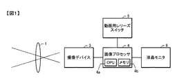
図1は、本発明の第1実施形態による動画撮影可能な電子カメラの概要を説明するブロック図である。図1において電子カメラは、撮影レンズ1と、CCDイメージセンサやCMOSイメージセンサなどで構成される撮像デバイス3と、CPU4aやメモリ4bなどで構成される画像プロセッサ4と、動画用レリーズスイッチ5と、表示装置としての液晶モニタ6と、を備えている。撮像デバイス3の撮像面上には、撮影レンズ1を通過した被写体光による被写体像が結像される。
Embodiments of the present invention will be described below with reference to the drawings.
<1. Configuration of First Embodiment (FIG. 1)>
FIG. 1 is a block diagram for explaining the outline of an electronic camera capable of moving image shooting according to the first embodiment of the present invention. In FIG. 1, an electronic camera includes a photographing
撮像デバイス3は、電子カメラの電源がオンされているとき、定常的に被写体像を繰り返し撮像するように構成されている。撮像デバイス3は、撮像時に被写体像の明るさに応じて画素ごとに信号電荷を蓄積する。蓄積電荷は、不図示の駆動回路から撮像デバイス3へ供給される駆動信号によって撮像デバイス3から順次掃き出される。信号電荷は不図示のアナログ信号処理回路で所定のアナログ処理をされた後、不図示のA/D変換回路によってデジタル撮像信号に変換されて画像プロセッサ4へ導かれる。 The imaging device 3 is configured to continually capture subject images when the electronic camera is powered on. The imaging device 3 accumulates signal charges for each pixel according to the brightness of the subject image during imaging. The accumulated charges are sequentially swept out from the imaging device 3 by a drive signal supplied to the imaging device 3 from a drive circuit (not shown). The signal charge is subjected to predetermined analog processing by an analog signal processing circuit (not shown), then converted to a digital image signal by an A / D conversion circuit (not shown), and guided to the image processor 4.
画像プロセッサ4は、撮像デバイス3に対する撮像時間(電荷蓄積時間)の指示などを行う。画像プロセッサ4はさらに、デジタル撮像信号に対してホワイトバランス調整処理や輪郭補償処理を行う他に、後述する基準パンニング方向に基づく補正処理等の画像処理を行う。画像処理後の画像データは、メモリ4bに記録され、更に液晶モニタ6に出力される。画像プロセッサ4は、動画用レリーズスイッチ5からレリーズ操作信号が入力されると動画撮影シーケンスを開始させ、撮像デバイス3からの電荷蓄積の掃き出し開始を指示するように構成されている。
The image processor 4 gives an instruction for an imaging time (charge accumulation time) to the imaging device 3. The image processor 4 further performs image processing such as correction processing based on a reference panning direction, which will be described later, in addition to performing white balance adjustment processing and contour compensation processing on the digital imaging signal. The image data after the image processing is recorded in the
このカメラでは、撮像デバイス3の読み出し方法を変更することにより、1/15秒や1/30秒といった短い周期で画像を連続して取得できるようになっており、これら短い周期で取得した一連の画像を保存することにより、動画像を保存することが可能になっている。ここでは、1/30秒に1コマの周期で画像を取り込む場合を例にとって説明する。また、この1コマをフレームと呼ぶ。 In this camera, by changing the readout method of the imaging device 3, images can be continuously acquired with a short cycle such as 1/15 seconds or 1/30 seconds, and a series of images acquired with these short cycles can be obtained. By saving an image, it is possible to save a moving image. Here, a case where an image is captured at a cycle of 1 frame per 1/30 seconds will be described as an example. One frame is called a frame.
<2.第1実施形態の作用(図2〜図6)>
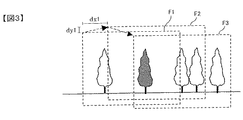
図2は、第1実施形態によるパンニング撮影および補正処理を説明するフローチャートである。図3〜図6は、この補正処理の過程を説明する図である。図3〜図6では、使用者が、水平方向、つまり重力方向に垂直な方向である右方向に、カメラを手持ち撮影でパンニングさせていると仮定している。右方向へのパンニングであるから、使用者は先ず、撮影したい範囲の最も左端に構図する。そこから使用者が希望する速度、例えば4秒間に1画面分移動する速度でパンニングを開始する。
<2. Action of First Embodiment (FIGS. 2 to 6)>
FIG. 2 is a flowchart for explaining panning photographing and correction processing according to the first embodiment. 3 to 6 are diagrams for explaining the process of the correction process. 3 to 6, it is assumed that the user pans the camera by hand-held shooting in the horizontal direction, that is, the right direction that is the direction perpendicular to the gravity direction. Since the panning is in the right direction, the user first composes the left end of the range to be photographed. From there, panning is started at a speed desired by the user, for example, at a speed of moving one screen per 4 seconds.
この明細書では、水平方向のパンニングをパンニング方向角0度、鉛直方向(重力方向)のパンニングをパンニング方向角90度と定義する。また、水平方向と鉛直方向に±45度の角度差を有する方向のパンニングをパンニング方向角45度および135度と定義する。 In this specification, panning in the horizontal direction is defined as a panning direction angle of 0 degrees, and panning in the vertical direction (gravity direction) is defined as a panning direction angle of 90 degrees. Further, panning in a direction having an angle difference of ± 45 degrees in the horizontal direction and the vertical direction is defined as panning direction angles of 45 degrees and 135 degrees.
図3は、パンニング撮影において静止した被写体に対する撮像画面の移動の様子を表した図である。F1、F2、F3で示す矩形の破線は、撮像デバイス3で撮像された各フレームの画像範囲を示している。 FIG. 3 is a diagram illustrating how the imaging screen moves with respect to a stationary subject in panning shooting. The rectangular broken lines indicated by F1, F2, and F3 indicate the image ranges of each frame imaged by the imaging device 3.
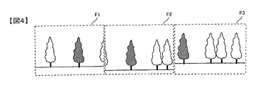
図4は、図3に示す構図で撮像された各フレームF1、F2、F3の画像を示す図である。図3に示された被写体に対する撮像画面の移動に応じて、図4のように、3枚の画像が撮像デバイス3にて撮像される。いま、最初のフレームF1の撮影から二番目のフレームF2の撮影までの間に、右方向にdx1、上方向にdy1だけ、撮像範囲が静止している被写体に対して撮像画面上で斜めに移動したとする。このdx1およびdy1の値を、本実施形態では、注目点の移動によって検出する。 FIG. 4 is a diagram illustrating images of the frames F1, F2, and F3 captured with the composition illustrated in FIG. In accordance with the movement of the imaging screen with respect to the subject shown in FIG. 3, three images are captured by the imaging device 3 as shown in FIG. Now, during the shooting of the first frame F1 to the shooting of the second frame F2, the subject whose imaging range is stationary is tilted on the imaging screen by dx 1 in the right direction and dy 1 in the upward direction. Suppose you move to. In the present embodiment, the values of dx 1 and dy 1 are detected by moving the point of interest.
図5は、実パンニング方向の求め方を示す説明図であり、図3および図4に示す最初のフレームF1の画像と二番目のフレームF2の画像とを、画像の各端縁が一致するように重ね合わせたものである。画像プロセッサ4は、最初のフレームF1において注目点を抽出する。注目点の抽出方法は、既に公知となっている顔位置判定技術その他の特徴抽出技術によることができる。例えば、画像内において、近傍の画素との明暗差が大きい領域や、近傍の画素と色相が異なる領域を抽出し、その領域の重心位置を算出することで注目点を抽出することができる。動画像撮影前にユーザが1枚の画像を取り込み、その中から注目点を任意に決定してもよい。なお、注目点となる被写体自身は静止しているものとする。 FIG. 5 is an explanatory diagram showing how to obtain the actual panning direction. The first frame F1 image and the second frame F2 image shown in FIGS. 3 and 4 are arranged so that their edges match. It is a superposition. The image processor 4 extracts a point of interest in the first frame F1. The attention point extraction method can be based on a known face position determination technique or other feature extraction technique. For example, a point of interest can be extracted by extracting a region having a large brightness difference from a neighboring pixel or a region having a hue different from that of a neighboring pixel in the image and calculating a centroid position of the region. The user may capture a single image before moving image shooting, and arbitrarily determine a point of interest from the captured image. It is assumed that the subject that is the point of interest is stationary.
画像プロセッサ4は、まず、最初のフレームF1の画像データを撮像デバイス3から取得し、メモリ4bに一時的に保存する(ステップS101)。そして、最初のフレームF1の画像データから注目点を抽出し、その座標データをメモリ4bに一時的に保存する(ステップS102)。
First, the image processor 4 acquires the image data of the first frame F1 from the imaging device 3, and temporarily stores it in the
最初のフレームF1の撮影後1/30秒を経過したら(ステップS103)、二番目のフレームF2の画像データを撮像デバイス3から取得し、メモリ4bに一時的に保存する(ステップS104)。そして、最初のフレームF1で抽出した注目点が、二番目のフレームF2のどの座標に位置するかを検出する(ステップS105)。なお、前フレームの注目点が現フレームの撮像範囲より外へ出てしまった場合は、注目点の座標検出ができない。この場合は、前フレームにも現フレームにも含まれる新たな注目点を抽出する。
When 1/30 seconds have elapsed after shooting of the first frame F1 (step S103), the image data of the second frame F2 is acquired from the imaging device 3 and temporarily stored in the
次に、最初のフレームF1の撮影から二番目のフレームF2の撮影までに撮像範囲内で注目点が移動した量である−dx1、−dy1を計算する(ステップS106)。ここで負記号を付けたのは、被写体に対する撮像範囲の移動方向と、撮像範囲内における被写体の移動方向とが、逆方向だからである(なお、右方向および上方向を正とした。)。図5では、「×」印で示される注目点が左方向にdx1、下方向にdy1だけ移動したことが表されている。このdx1、dy1より、下式を用いて、移動の角度θ1を計算する(ステップS107)。これにより、実際にカメラが動かされた実パンニング方向が検出される。
θ1=tan−1(dy1/dx1)
Next, −dx 1 and −dy 1 , which are amounts of movement of the point of interest within the imaging range from the first frame F1 to the second frame F2, are calculated (step S106). The reason why the negative sign is added here is that the moving direction of the imaging range relative to the subject and the moving direction of the subject within the imaging range are opposite (the right direction and the upward direction are positive). FIG. 5 shows that the point of interest indicated by the “x” mark has moved by dx 1 in the left direction and dy 1 in the downward direction. From the dx 1 and dy 1 , the movement angle θ 1 is calculated using the following equation (step S 107). Thereby, the actual panning direction in which the camera is actually moved is detected.
θ 1 = tan −1 (dy 1 / dx 1 )
なお、実パンニング方向は0度〜360度の角度として計算されるので、実パンニング方向が、上述したパンニング方向角0度、パンニング方向角90度、パンニング方向角45度およびパンニング方向角135度のいずれに該当するかを、後述するアルゴリズムにより決定する。 Since the actual panning direction is calculated as an angle of 0 degrees to 360 degrees, the actual panning direction is the above-described panning direction angle of 0 degree, panning direction angle of 90 degrees, panning direction angle of 45 degrees, and panning direction angle of 135 degrees. Which one corresponds is determined by an algorithm described later.
ところで、カメラに内蔵したメモリ4bには、あらかじめ0度(水平方向であり、180度を含む)、90度(重力方向であり、270度を含む)、45度(0度と90度の中間の方向であり、225度を含む)、135度(90度と180度の中間の方向であり、315度を含む)の4つの方向角が基準パンニング方向角θ0として記憶されている。これらの方向は、一般的にパンニングされる方向の代表的なものである。いうまでもなく、もっと細かいあるいは粗い間隔でもよいし、角度間隔は等間隔でなくてもよい。なお、0/45/90/135度の一部を含むように方向角を記憶してもよい。
By the way, in the
画像プロセッサ4は、求めた実パンニング方向角θ1に最も近い角度を、上記記憶されている角度の中から選択することにより、補正処理の基準となる基準パンニング方向角θ0を決定する(ステップS108)。具体的には、次の(a)〜(i)に基づいて基準パンニング方向角θ0を決定する。 The image processor 4 determines the reference panning direction angle θ 0 as a reference for the correction process by selecting an angle closest to the obtained actual panning direction angle θ 1 from the stored angles (step 0). S108). Specifically, the reference panning direction angle θ 0 is determined based on the following (a) to (i).
(a)0度≦実パンニング方向角θ1<22.5度
(b)157.5度≦実パンニング方向角θ1<202.5度
(c)337.5度≦実パンニング方向角θ1<360度
のいずれかの場合は、基準パンニング方向角θ0は0度(水平方向)とする。
(d)67.5度≦実パンニング方向角θ1<112.5度
(e)247.5度≦実パンニング方向角θ1<292.5度
のいずれかの場合は、基準パンニング方向角θ0は90度(垂直方向)とする。
(f)22.5度≦実パンニング方向角θ1<67.5度
(g)202.5度≦実パンニング方向角θ1<247.5度
のいずれかの場合は、基準パンニング方向角θ0は45度(右上がり斜め方向)とする。
(h)112.5度≦実パンニング方向角θ1<157.5度
(i)292.5度≦実パンニング方向角θ1<337.5度
のいずれかの場合は、基準パンニング方向角θ0は135度(左上がり斜め方向)とする。
図3および図4の例では水平パンニングを想定しているから、実パンニング方向角θ1が上記(a)〜(c)のいずれかの角度範囲内であり、主移動方向はX方向(水平方向)であると判定し、基準パンニング方向角θ0は0度と決定する。
(A) 0 degree ≦ actual panning direction angle θ 1 <22.5 degrees (b) 157.5 degrees ≦ actual panning direction angle θ 1 <202.5 degrees (c) 337.5 degrees ≦ actual panning direction angle θ 1 In any case of <360 degrees, the reference panning direction angle θ 0 is set to 0 degrees (horizontal direction).
(D) 67.5 degrees ≦ actual panning direction angle θ 1 <112.5 degrees (e) 247.5 degrees ≦ actual panning direction angle θ 1 <292.5 degrees, the reference panning direction angle θ 0 is 90 degrees (vertical direction).
(F) 22.5 degrees ≦ actual panning direction angle θ 1 <67.5 degrees (g) If 202.5 degrees ≦ actual panning direction angle θ 1 <247.5 degrees, the reference panning direction angle θ 0 is 45 degrees (upward diagonal direction).
(H) 112.5 degrees ≦ actual panning direction angle θ 1 <157.5 degrees (i) 292.5 degrees ≦ actual panning direction angle θ 1 <337.5 degrees 0 is 135 degrees (left-up diagonal direction).
Since it is assumed that horizontal panning in the example of FIG. 3 and FIG. 4, is within any range of angles actual panning direction angle theta 1 is above (a) ~ (c), the main movement direction is the X direction (horizontal Direction) and the reference panning direction angle θ 0 is determined to be 0 degree.
そして、実パンニング方向角θ1と基準パンニング方向角θ0が異なる場合は(ステップS109:YES)、動画像の移動方向が基準パンニング方向に一致するように補正する。この補正は、例えば、次に説明するように画像の位置の移動により行う。 If the actual panning direction angle θ 1 and the reference panning direction angle θ 0 are different (step S109: YES), correction is made so that the moving direction of the moving image matches the reference panning direction. This correction is performed, for example, by moving the position of the image as described below.
まず、ステップS110において、基準パンニング方向角θ0に基づき、画像をずらして補正する方向(以下、画像補正方向とする)がX方向かY方向かの判定を行う。例えば、実パンニング方向角θ1が上記(a)〜(c)のいずれかであって基準パンニング方向角θ0が0度と決定されている場合は、画像補正方向はY方向(垂直方向)であると判定する。なお、図3〜図6の例に示される基準パンニング方向は水平方向であるので上記の角度範囲内であり、画像補正方向はY方向と判定される。 First, in step S110, based on the reference panning direction angle theta 0, the direction of correcting by shifting the image (hereinafter, the image correction direction) and determines whether the X direction or Y direction. For example, when the actual panning direction angle θ 1 is any one of the above (a) to (c) and the reference panning direction angle θ 0 is determined to be 0 degrees, the image correction direction is the Y direction (vertical direction). It is determined that Since the reference panning direction shown in the examples of FIGS. 3 to 6 is the horizontal direction, it is within the above angle range, and the image correction direction is determined to be the Y direction.
そして、θ0で示される基準パンニング方向にパンニングした場合の、被写体に対する撮像範囲の重力方向の移動量dy1’を、下の式により求める(ステップS111)。
dy1’/dx1=tanθ0 より、
dy1’=dx1×tanθ0
dy1’が求められたら、二番目のフレームF2の画像を(dy1−dy1’)だけ上方向に移動する(ステップS112)。これにより、角度θ0のパンニングが行われたことと等価になる。画像を移動するには、例えば二番目のフレームF2の画像の上部を(dy1−dy1’)だけ削り、一番目、二番目のフレームF1、F2の上端を揃えればよい。なお、(dy1−dy1’)が負であれば、二番目のフレームF2の画像を下方向に移動する。
Then, the amount of movement dy 1 ′ in the gravitational direction of the imaging range with respect to the subject when panning in the reference panning direction indicated by θ 0 is obtained by the following equation (step S111).
From dy 1 ′ / dx 1 = tan θ 0 ,
dy 1 ′ = dx 1 × tan θ 0
When dy 1 ′ is obtained, the image of the second frame F2 is moved upward by (dy 1 −dy 1 ′) (step S112). This makes it equivalent to panning angle theta 0 is performed. In order to move the image, for example, the upper part of the image of the second frame F2 is scraped by (dy 1 -dy 1 ′), and the upper ends of the first and second frames F1, F2 may be aligned. If (dy 1 −dy 1 ′) is negative, the image of the second frame F2 is moved downward.
一方、ステップS110において、例えば、実パンニング方向角θ1が上記(d)〜(e)のいずれかであって基準パンニング方向角θ0が90度と決定されている場合は、画像補正方向はX方向(水平方向)であると判定する。
そして、θ0で示される基準パンニング方向にパンニングした場合の、被写体に対する撮像範囲の水平方向の移動量dx1’を、下の式により求める(ステップS113)。
dx1’/dy1=tanθ0 より、
dx1’=dy1×tanθ0
On the other hand, in step S110, for example, if the actual panning direction angle theta 1 is above (d) ~ standard panning direction angle theta 0 be either (e) is determined as 90 degrees, the image correction direction It is determined that the direction is the X direction (horizontal direction).
Then, the horizontal movement amount dx 1 ′ of the imaging range with respect to the subject when panning in the reference panning direction indicated by θ 0 is obtained by the following equation (step S113).
From dx 1 ′ / dy 1 = tan θ 0 ,
dx 1 '= dy 1 × tan θ 0
dx1’が求められたら、二番目のフレームF2の画像を(dx1−dx1’)だけ右方向に移動する(ステップS114)。これにより、角度θ0のパンニングが行われたことと等価になる。画像を移動するには、例えば二番目のフレームF2の画像の右端部を(dx1−dx1’)だけ削り、一番目、二番目のフレームF1、F2の右端を揃えればよい。なお、(dx1−dx1’)が負であれば、二番目のフレームF2の画像を左方向に移動する。 When dx 1 ′ is obtained, the image of the second frame F2 is moved rightward by (dx 1 −dx 1 ′) (step S114). This makes it equivalent to panning angle theta 0 is performed. In order to move the image, for example, the right end portion of the image of the second frame F2 may be trimmed by (dx 1 −dx 1 ′), and the right ends of the first and second frames F1 and F2 may be aligned. If (dx 1 −dx 1 ′) is negative, the image of the second frame F2 is moved leftward.
なお、実パンニング方向角θ1が上記(f)〜(g)のいずれかであって基準パンニング方向角θ0が45度と決定されている場合、および、上記(h)〜(i)のいずれかであって基準パンニング方向角θ0が135度と決定されている場合は、画像補正方向をX方向と判定してもよいし、画像補正方向をY方向と判定してもよい。また、画像補正方向の判定は、実パンニング方向角度に基づいて、たとえば以下のように決定してもよい。この場合、たとえば、実パンニング方向角θ1が水平方向0度を基準として±45度の範囲内であれば、画像補正方向をY方向とし、実パンニング方向角θ1が垂直方向90度を基準として±45度の範囲内であれば、画像補正方向をX向としてもよい。このような決定により、補正のための画像削り量を低減できる。また、主移動方向はX方向とY方向から選択しているが、これに限らず、他の方向を選択肢に加えても良い。 The actual panning direction angle θ 1 is any one of the above (f) to (g), and the reference panning direction angle θ 0 is determined to be 45 degrees, and the above (h) to (i) If the reference panning direction angle θ 0 is determined to be 135 degrees, the image correction direction may be determined as the X direction, and the image correction direction may be determined as the Y direction. The determination of the image correction direction may be determined as follows based on the actual panning direction angle, for example. In this case, for example, if the actual panning direction angle θ 1 is within ± 45 degrees with respect to the horizontal direction of 0 degrees, the image correction direction is the Y direction, and the actual panning direction angle θ 1 is the reference of the vertical direction of 90 degrees. As long as it is within a range of ± 45 degrees, the image correction direction may be the X direction. By such determination, the amount of image shaving for correction can be reduced. The main movement direction is selected from the X direction and the Y direction. However, the present invention is not limited to this, and other directions may be added to the options.
画像の移動が終わった場合、或いは実パンニング方向角θ1と基準パンニング方向角θ0が異ならないために補正が必要なかった場合は(ステップS109:NO)、補正後の当該フレームの画像をメモリ4bに保存し液晶モニタ6で表示する(ステップS115)。こうして、補正処理によりパンニング方向の安定した動画像を、リアルタイムで液晶モニタ6に表示させることが望ましい。 When the movement of the image is completed, or when the actual panning direction angle θ 1 and the reference panning direction angle θ 0 are not different and correction is not necessary (step S109: NO), the image of the corrected frame is stored in the memory. 4b and displayed on the liquid crystal monitor 6 (step S115). In this way, it is desirable to display a stable moving image in the panning direction on the liquid crystal monitor 6 in real time by the correction process.
更に、動画像の撮影終了か否かを判定し、撮影が終了していなければ(ステップS116:NO)、ステップS103に戻って1/30秒の経過を待つ。三番目のフレームF3以降も同様にして、構図移動後の注目点の座標を検出し、二番目のフレームF2の注目点座標からの移動角度を計算し、基準パンニング方向を選択して、これに合うように補正する。 Further, it is determined whether or not the moving image has been shot. If the shooting has not been finished (step S116: NO), the process returns to step S103 and waits for 1/30 seconds. Similarly, after the third frame F3, the coordinates of the attention point after composition movement are detected, the movement angle from the attention point coordinates of the second frame F2 is calculated, the reference panning direction is selected, and Correct to fit.
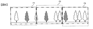
図6の一点鎖線で示すフレームは、図4に対する補正後の各フレームF1,F2,F3の画像の例を示す図である。ここでは重力方向の補正がされているので、フレーム間で上下のブレがなく、安定したパンニング動画像が得られている。
動画像の撮影が終了すれば(ステップS116:YES)、一連の処理を終了する。
6 is a diagram illustrating an example of images of the frames F1, F2, and F3 after correction with respect to FIG. Here, since the gravity direction is corrected, there is no vertical blur between frames, and a stable panning moving image is obtained.
When shooting of the moving image ends (step S116: YES), a series of processing ends.
<3.第1実施形態の効果>
本実施形態によれば次の作用効果を得ることができる。
(1)パンニング方向のばらつきを小さくしてパンニング方向の安定した動画像を得ることができる。
(2)基準パンニング方向を4方向から選択するので、基準パンニング方向を容易に決定することができる。また、基準パンニング方向は、上記4方向のうち、実パンニング方向に最も近いものが選択されるので、撮影者の意図に合致した自然な補正済み動画像を得ることができる。
(3)動画像の一部を切り出すことにより補正を行うので、ソフトウェアによる処理だけで補正処理を行うことができる。
(4)補正処理によりパンニング方向の安定した動画像を、リアルタイムで液晶モニタ6に表示させることができるので、撮影中の動画像をパンニング補正後の状態で確認しながら撮影を行うことができる。
(5)動画像内の注目点の移動量に基づいて実パンニング方向を検出するので、動画像データのみに基づいて実パンニング方向を検出することができる。
<3. Effects of First Embodiment>
According to this embodiment, the following effects can be obtained.
(1) A stable moving image in the panning direction can be obtained by reducing variations in the panning direction.
(2) Since the reference panning direction is selected from four directions, the reference panning direction can be easily determined. Also, since the reference panning direction is selected from the four directions that are closest to the actual panning direction, a natural corrected moving image that matches the photographer's intention can be obtained.
(3) Since the correction is performed by cutting out a part of the moving image, the correction process can be performed only by processing by software.
(4) Since the moving image stable in the panning direction can be displayed on the liquid crystal monitor 6 in real time by the correction process, it is possible to perform shooting while confirming the moving image being shot in the state after the panning correction.
(5) Since the actual panning direction is detected based on the amount of movement of the point of interest in the moving image, the actual panning direction can be detected based only on the moving image data.
なお、基準パンニング方向角θ0と実パンニング方向角θ1との差によっては、画像の周囲が多少削られて見えることがあるが、正確な角度のパンニングが実現できる効果の方が大きいし、ズームレンズがあれば多少広角側にセットしておけば大きな問題にはならない。 Note that depending on the difference between the reference panning direction angle θ 0 and the actual panning direction angle θ 1 , the periphery of the image may appear to be slightly shaved, but the effect of realizing accurate angle panning is greater. If you have a zoom lens, it will not be a big problem if you set it to the wide-angle side.
<4.第2実施形態の構成(図7)>
次に第2実施形態として、パンニング方向を角速度/加速度センサにより検出する場合を説明する。
<4. Configuration of Second Embodiment (FIG. 7)>
Next, a case where the panning direction is detected by an angular velocity / acceleration sensor will be described as a second embodiment.
図7は、本発明の第2実施形態による動画撮影可能な電子カメラの概要を説明するブロック図である。図1と同様の部分には同一の符号を付して説明を省略する。この電子カメラは、図1の電子カメラに加え、カメラ回転センサ群7および撮像デバイス移動機構9を備えている。 FIG. 7 is a block diagram for explaining the outline of an electronic camera capable of moving image shooting according to the second embodiment of the present invention. Components similar to those in FIG. 1 are denoted by the same reference numerals and description thereof is omitted. This electronic camera includes a camera rotation sensor group 7 and an imaging device moving mechanism 9 in addition to the electronic camera of FIG.
カメラ回転センサ群7は、角速度センサまたは加速度センサより構成され、カメラの回転による水平方向(X方向)および重力方向(Y方向)の撮影方向の変化θxおよびθyを検出する。検出された撮影方向の変化は画像プロセッサ4に送られる。画像プロセッサ4は、カメラ回転センサ群7から受信する撮影方向の変化を示す信号に基づき、撮像デバイス移動機構9に対して撮像デバイス3の移動信号を送信する。 The camera rotation sensor group 7 is composed of an angular velocity sensor or an acceleration sensor, and detects a change in imaging direction θx and θy in the horizontal direction (X direction) and the gravitational direction (Y direction) due to the rotation of the camera. The detected change in photographing direction is sent to the image processor 4. The image processor 4 transmits a movement signal of the imaging device 3 to the imaging device movement mechanism 9 based on a signal indicating a change in the imaging direction received from the camera rotation sensor group 7.
撮像デバイス移動機構9は、圧電素子などの駆動素子を備え、画像プロセッサ4からの信号に基づいて、光軸に対して垂直な面内で撮像デバイス3を微小量移動させることができる。カメラ回転センサ群7および撮像デバイス移動機構9は、手振れ補正に使用されるものをパンニング撮影時の角度変化の検知および補正処理にも共用することができる。 The imaging device moving mechanism 9 includes a driving element such as a piezoelectric element, and can move the imaging device 3 by a minute amount in a plane perpendicular to the optical axis based on a signal from the image processor 4. The camera rotation sensor group 7 and the imaging device moving mechanism 9 can also share the one used for camera shake correction for the detection and correction processing of the angle change during panning shooting.
カメラ回転センサ群7の具体的構成としては、例えば、2つの角速度センサを設け、それぞれ被写体に対するカメラのY軸周り(水平方向)の角速度と、X軸周り(重力方向)の角速度とを検知できるようにすれば良い。これらの角速度をそれぞれ時間tについて1回積分すれば、それぞれ水平方向の回転角θxと重力方向の回転角θyを算出することができる。 As a specific configuration of the camera rotation sensor group 7, for example, two angular velocity sensors are provided, and each can detect an angular velocity around the Y axis (horizontal direction) and an angular velocity around the X axis (gravity direction) with respect to the subject. You can do that. If these angular velocities are integrated once for each time t, the horizontal rotation angle θx and the gravitational rotation angle θy can be calculated.
また、カメラ回転センサ群7の他の具体的構成としては、例えば、3つの加速度センサを設けても良い。そのうち水平方向に並べて配置された2つの加速度センサの出力差に基づいて水平方向の角加速度を検知し、これと異なる組み合わせで重力方向に並べて配置された2つの加速度センサの出力差に基づいて重力方向の角加速度を検知することができる。これらの角加速度をそれぞれ時間tについて2回積分すれば、それぞれ水平方向の回転角θxと重力方向の回転角θyを算出することができる。 Further, as another specific configuration of the camera rotation sensor group 7, for example, three acceleration sensors may be provided. Of these, the angular acceleration in the horizontal direction is detected based on the output difference between the two acceleration sensors arranged side by side in the horizontal direction, and the gravity based on the output difference between the two acceleration sensors arranged in the gravity direction in a different combination. The angular acceleration in the direction can be detected. If these angular accelerations are integrated twice for each time t, the horizontal rotation angle θx and the gravitational rotation angle θy can be calculated.
<5.第2実施形態の作用(図8)>
このようにして求めた水平方向の回転角θxおよび重力方向の回転角θyを用いて、被写体に対する撮像範囲の撮影画面上の水平方向の移動量dx2および重力方向の移動量dy2は、次式で求めることが出来る。
dx2=αθx
dy2=αθy
αは撮影時におけるレンズの焦点距離に比例した係数で、レンズの焦点距離により異なる。こうして求めたdx2、dy2に基づき、カメラが移動した方向角すなわち実パンニング方向角θ2は、以下の式で求められる。
θ2=tan−1(dy2/dx2)
=tan−1(αθy/αθx)
=tan−1(θy/θx)
<5. Operation of Second Embodiment (FIG. 8)>
Using the horizontal rotation angle θx and the gravitational direction rotation angle θy thus determined, the horizontal movement amount dx 2 and the gravitational movement amount dy 2 of the imaging range for the subject are expressed as follows: It can be calculated by the formula.
dx 2 = αθx
dy 2 = αθy
α is a coefficient proportional to the focal length of the lens at the time of photographing, and varies depending on the focal length of the lens. Based on dx 2 and dy 2 obtained in this way, the direction angle in which the camera has moved, that is, the actual panning direction angle θ 2 is obtained by the following equation.
θ 2 = tan −1 (dy 2 / dx 2 )
= Tan −1 (αθy / αθx)
= Tan −1 (θy / θx)
その他は第1実施形態と同様に、求めた実パンニング方向角θ2に基づいて基準パンニング方向角θ0を選択し、θ2とθ0が異なる場合には、θ0に一致する方向になるように画像を移動する。 Other than the first embodiment, the reference panning direction angle θ 0 is selected based on the obtained actual panning direction angle θ 2 , and when θ 2 and θ 0 are different, the direction coincides with θ 0. Move the image so that.
図8は、第2実施形態によるパンニング撮影および補正処理を説明するフローチャートである。
画像プロセッサ4は、まず、最初のフレームの画像データを撮像デバイス3から取得し、メモリ4bに一時的に保存する(ステップS201)。そして、カメラ回転センサ群7の出力に基づき、水平方向(X方向)および重力方向(Y方向)の回転角の計測を開始する(ステップS202)。
FIG. 8 is a flowchart for explaining panning photographing and correction processing according to the second embodiment.
First, the image processor 4 acquires the image data of the first frame from the imaging device 3, and temporarily stores it in the
最初のフレームの撮影後1/30秒を経過したら(ステップS203)、二番目のフレームの画像データを撮像デバイス3から取得し、メモリ4bに一時的に保存する(ステップS204)。そして、被写体に対するカメラの水平方向の回転角θxおよび重力方向の回転角θyを算出する(ステップS205)。
When 1/30 seconds have elapsed after the first frame is shot (step S203), the image data of the second frame is acquired from the imaging device 3 and temporarily stored in the
次に、水平方向の回転角θxおよび重力方向の回転角θyに基づき、最初のフレームの撮影から二番目のフレームの撮影までに、被写体に対して撮像範囲が水平方向に移動した量dx2および重力方向に移動した量dy2を計算する(ステップS206)。このdx2およびdy2、すなわち、θx,θyより、下式を用いて、移動の角度θ2を計算する(ステップS207)。これにより、実際にカメラが動かされた実パンニング方向が検出される。
θ2=tan−1(θy/θx)
Next, based on the rotation angle θx in the horizontal direction and the rotation angle θy in the gravitational direction, the amount dx 2 that the imaging range has moved in the horizontal direction with respect to the subject from the first frame to the second frame. calculating an amount dy 2 moved in the direction of gravity (step S206). From the dx 2 and dy 2, that is, θx and θy, the movement angle θ 2 is calculated using the following equation (step S207). Thereby, the actual panning direction in which the camera is actually moved is detected.
θ 2 = tan −1 (θy / θx)
カメラに内蔵したメモリ4bには、第1の実施形態で説明したと同様に、基準パンニング方向角として、あらかじめ例えば0度、90度、45度、135度の4つの方向角が記憶されている。基準パンニング方向角は上述したと同様に種々の決め方がある。
In the
画像プロセッサ4は、求めたθ2に最も近い角度を、上記記憶されている角度の中から選択することにより、補正処理の基準となる基準パンニング方向角θ0を決定する(ステップS208)。そして、実パンニング方向角θ2と基準パンニング方向角θ0が異なる場合は(ステップS209:YES)、動画像の移動方向が基準パンニング方向に一致するように補正する。この補正は、例えば、次に説明するように画像の位置の移動により行う。 The image processor 4 determines a reference panning direction angle θ 0 as a reference for correction processing by selecting an angle closest to the obtained θ 2 from the stored angles (step S208). If the actual panning direction angle θ 2 and the reference panning direction angle θ 0 are different (step S209: YES), correction is made so that the moving direction of the moving image matches the reference panning direction. This correction is performed, for example, by moving the position of the image as described below.
まず、ステップS210において、基準パンニング方向角θ0に基づき、画像補正方向がX方向かY方向かの判定を行う。例えば、実パンニング方向角θ1が上記(a)〜(c)のいずれかであって基準パンニング方向角θ0が0度と決定されている場合は、画像補正方向はY方向(垂直方向)であると判定する。 First, in step S210, based on the reference panning direction angle theta 0, the image correction direction and determines whether the X direction or Y direction. For example, if the actual panning direction angle θ1 is determined as above (a) ~ one in a reference panning direction angle theta 0 to 0 degrees (c), the image correction direction is the Y direction (vertical direction) Judge that there is.
そして、θ0で示される基準パンニング方向にパンニングした場合の、被写体に対する撮像範囲の重力方向の移動量dy2’を、下の式により求める(ステップS211)。
dy2’/dx2=tanθ0 より、
dy2’=dx2×tanθ0
dy2’が求められたら、二番目のフレームの画像を(dy2−dy2’)だけ上方向に移動する(ステップS212)。これにより、角度θ0のパンニングが行われたことと等価になる。画像を移動するには、例えば二番目のフレームの画像の上部を(dy2−dy2’)だけ削り、一番目、二番目のフレームの上端を揃えればよい。なお、(dy2−dy2’)が負であれば、二番目のフレームの画像を下方向に移動する。
Then, the amount of movement dy 2 ′ in the gravitational direction of the imaging range with respect to the subject when panning in the reference panning direction indicated by θ 0 is obtained by the following equation (step S211).
From dy 2 ′ / dx 2 = tan θ 0 ,
dy 2 ′ = dx 2 × tan θ 0
When dy 2 ′ is obtained, the image of the second frame is moved upward by (dy 2 −dy 2 ′) (step S212). This makes it equivalent to panning angle theta 0 is performed. In order to move the image, for example, the upper part of the image of the second frame may be scraped by (dy 2 −dy 2 ′) and the upper ends of the first and second frames may be aligned. If (dy 2 −dy 2 ′) is negative, the image of the second frame is moved downward.
一方、ステップS210において、例えば、実パンニング方向角θ2が上記(d)〜(e)のいずれかであって基準パンニング方向角θ0が90度と決定されている場合は、画像補正方向はX方向(水平方向)であると判定する。
そして、θ0で示される基準パンニング方向にパンニングした場合の、被写体に対する撮像範囲の水平方向の移動量dx2’を、下の式により求める(ステップS213)。
dx2’/dy2=tanθ0 より、
dx2’=dy2×tanθ0
On the other hand, in step S210, for example, if the actual panning direction angle θ2 is the (d) ~ standard panning direction angle theta 0 be either (e) is determined as 90 degrees, the image correction direction X The direction (horizontal direction) is determined.
Then, the horizontal movement amount dx 2 ′ of the imaging range with respect to the subject when panning in the reference panning direction indicated by θ 0 is obtained by the following equation (step S213).
From dx 2 '/ dy 2 = tan θ 0 ,
dx 2 '= dy 2 × tan θ 0
dx2’が求められたら、二番目のフレームの画像を(dx2−dx2’)だけ右方向に移動する(ステップS214)。これにより、角度θ0のパンニングが行われたことと等価になる。画像を移動するには、例えば二番目のフレームの画像の右端部を(dx2−dx2’)だけ削り、一番目、二番目のフレームの右端を揃えればよい。なお、(dx2−dx2’)が負であれば、二番目のフレームの画像を左方向に移動する。 When dx 2 ′ is obtained, the image of the second frame is moved rightward by (dx 2 −dx 2 ′) (step S214). This makes it equivalent to panning angle theta 0 is performed. In order to move the image, for example, the right end of the image of the second frame may be trimmed by (dx 2 −dx 2 ′) and the right ends of the first and second frames may be aligned. If (dx 2 −dx 2 ′) is negative, the image of the second frame is moved leftward.
なお、実パンニング方向角θ1が上記(f)〜(g)のいずれかであって基準パンニング方向角θ0が45度と決定されている場合、および、上記(h)〜(i)のいずれかであって基準パンニング方向角θ0が135度と決定されている場合は、画像補正方向をX方向と判定してもよいし、画像補正方向をY方向と判定してもよい。また、画像補正方向の判定は、実パンニング方向角度に基づいてたとえば以下のように決定してもよい。この場合、たとえば、実パンニング方向角θ2が水平方向0度を基準として±45度の範囲内であれば、画像補正方向をY方向とし、実パンニング方向角θ2が垂直方向90度を基準として±45度の範囲内であれば、画像補正方向をX方向としてもよい。このような決定により、補正のための画像削り量を低減できる。また、画像補正方向はX方向とY方向から選択しているが、これに限らず、他の方向を選択肢に加えても良い。 The actual panning direction angle θ 1 is any one of the above (f) to (g) and the reference panning direction angle θ 0 is determined to be 45 degrees, and the above (h) to (i) If the reference panning direction angle θ 0 is determined to be 135 degrees, the image correction direction may be determined as the X direction, or the image correction direction may be determined as the Y direction. The determination of the image correction direction may be determined as follows based on the actual panning direction angle, for example. In this case, for example, if the actual panning direction angle θ 2 is within a range of ± 45 degrees with respect to the horizontal direction of 0 degrees, the image correction direction is the Y direction, and the actual panning direction angle θ 2 is the reference of the vertical direction of 90 degrees. As long as it is within a range of ± 45 degrees, the image correction direction may be the X direction. By such determination, the amount of image shaving for correction can be reduced. The image correction direction is selected from the X direction and the Y direction. However, the direction is not limited to this, and other directions may be added to the options.
画像の移動が終わった場合、或いは実パンニング方向角θ2と基準パンニング方向角θ0が異ならないために補正が必要なかった場合は(ステップS209:NO)、補正後の当該フレームの画像をメモリ4bに保存し液晶モニタ6で表示する(ステップS215)。こうして、補正処理によりパンニング方向の安定した動画像を、リアルタイムで液晶モニタ6に表示させることが望ましい。 When the movement of the image is finished, or when the actual panning direction angle θ 2 and the reference panning direction angle θ 0 do not differ and correction is not necessary (step S209: NO), the image of the corrected frame is stored in the memory. It is stored in 4b and displayed on the liquid crystal monitor 6 (step S215). In this way, it is desirable to display a stable moving image in the panning direction on the liquid crystal monitor 6 in real time by the correction process.
更に、動画像の撮影終了か否かを判定し(ステップS216)、撮影が終了していなければ、ステップS203に戻って1/30秒の経過を待つ。三番目のフレーム以降も同様にして、カメラの回転角を計測して実パンニング方向を計算し、基準パンニング方向を選択して、これに合うように補正する。
動画像の撮影が終了すれば、一連の処理を終了する。
Further, it is determined whether or not shooting of a moving image has ended (step S216). If shooting has not ended, the process returns to step S203 and waits for 1/30 seconds. Similarly for the third and subsequent frames, the rotation angle of the camera is measured to calculate the actual panning direction, the reference panning direction is selected, and correction is made to match this.
When shooting of the moving image ends, a series of processing ends.
<6.第2実施形態の効果>
本実施形態によれば第1実施形態と同様の作用効果を得ることができる。また、電子カメラ内に配置された角速度センサまたは加速度センサの出力に基づいて実パンニング方向を検出するので、重力方向に対する角度も正確に検出することができる。
<6. Effect of Second Embodiment>
According to this embodiment, the same effect as that of the first embodiment can be obtained. Further, since the actual panning direction is detected based on the output of the angular velocity sensor or the acceleration sensor arranged in the electronic camera, the angle with respect to the gravity direction can also be accurately detected.
<7.変形例>
上記の第1および第2実施形態において、上記の説明においては最初のフレームと二番目のフレームにより基準パンニング方向角θ0を決定したが、もっと多くのフレーム間での移動方向を算出して、その平均その他の代表値からθ0を求めてもよい。この場合、基準パンニング方向の算出に使用した各フレームの画像データは、基準パンニング方向が算出されてから個別に位置を補正され、記録されるものとする。
<7. Modification>
In the above first and second embodiments, in the above description, the reference panning direction angle θ 0 is determined by the first frame and the second frame, but the movement direction between more frames is calculated, Θ 0 may be obtained from the average and other representative values. In this case, it is assumed that the image data of each frame used for calculation of the reference panning direction is individually corrected in position and recorded after the reference panning direction is calculated.
上記の第1および第2実施形態において、上記の説明では画像の一部を削り、その削る位置を変更することによって補正を行ったが、補正の方法はこれに限られるものではない。例えば、第2実施形態の電子カメラが備えるような撮像デバイス移動機構9を用いて撮像デバイス3を微小量動かすことや、撮影光を偏向して像ブレを抑制する像ブレ補正光学系を撮影レンズ内に配置することにより撮像面上での画像位置を変更する、あるいは、画像取得範囲変更手段としての画像プロッセサ4の制御に基づいて、撮像デバイスによる撮像面上の画像取得範囲を電気的に変更するなど、手振れ補正用の機構を用いることもできる。このような補正方法をとれば、動画像データの一部を切り出す必要がないので、画質を損ねたりデータを無駄にしたりすることなく、かつほぼリアルタイムで補正を行うことができる。また、手振れ補正用にもそれらの機構を兼用することができる。 In the first and second embodiments described above, in the above description, correction is performed by cutting a part of the image and changing the position to be cut, but the correction method is not limited to this. For example, the image pickup device 3 is moved by a small amount using the image pickup device moving mechanism 9 provided in the electronic camera of the second embodiment, or an image blur correction optical system that suppresses image blur by deflecting shooting light is used as a shooting lens. The image acquisition range on the imaging plane by the imaging device is changed electrically based on the control of the image processor 4 as the image acquisition range changing means. For example, a camera shake correction mechanism can be used. If such a correction method is used, it is not necessary to cut out a part of the moving image data, so that correction can be performed almost in real time without degrading the image quality or wasting data. Further, these mechanisms can also be used for camera shake correction.
なお、撮像デバイスを移動する方式や像ブレ補正光学系を使用する方式では、注目点の移動量からパンニング方向を算出して基準パンニング方向との差を計算する画像処理方式を採用せず、角速度センサなどを使用して上記差を計算するのが望ましい。 Note that the method that moves the imaging device and the method that uses the image stabilization optical system do not use an image processing method that calculates the panning direction from the amount of movement of the point of interest and calculates the difference from the reference panning direction. It is desirable to calculate the difference using a sensor or the like.
上記の第1および第2実施形態において、上記の説明では撮影と同時にほぼリアルタイムで補正を実行して補正後の画像をモニタ表示する方法を説明したが、全て撮影が終了した後で補正を行っても良い。例えば、撮影した画像データをたとえばパーソナルコンピュータに読み込み、動画編集用のソフトウエア等を使用してパンニング方向を解析し、パンニング方向の安定したパンニング動画像となるように各フレームの位置を補正し、補正後の動画像を記録媒体に記録し、モニタ表示する場合にも本技術は有効である。 In the first and second embodiments described above, the description has been given of the method of executing correction in almost real time simultaneously with shooting and displaying the corrected image on the monitor. However, the correction is performed after all shooting is completed. May be. For example, the captured image data is read into, for example, a personal computer, the panning direction is analyzed using a moving image editing software, etc., and the position of each frame is corrected so that a stable panning moving image in the panning direction is obtained. The present technology is also effective when a corrected moving image is recorded on a recording medium and displayed on a monitor.
この場合、パーソナルコンピュータに図9に示すような処理を実行するプログラムをインストールする。すなわち、パンニングしながら撮影した動画像を編集するプログラムあって、動画像を読み込む処理(ステップS310)と、読み込んだ動画像に基づいてカメラの実パンニング方向を検出する検出処理(ステップS320)と、実パンニング方向と予め設定された基準パンニング方向との差を算出する算出処理(ステップS330)と、算出された差に基づき、取得される動画像のパンニング方向が基準パンニング方向に近づくように補正する補正処理(ステップS340)とをコンピュータで実行する動画像編集用プログラムである。ステップS320は、たとえば図2のステップS102〜ステップS107に相当する処理であり、ステップS330は図2のステップS110,ステップS111,ステップS113に相当する処理である。 In this case, a program for executing processing as shown in FIG. 9 is installed in the personal computer. That is, there is a program for editing a moving image shot while panning, a processing for reading a moving image (step S310), a detection processing for detecting the actual panning direction of the camera based on the read moving image (step S320), A calculation process (step S330) for calculating a difference between the actual panning direction and a preset reference panning direction, and based on the calculated difference, correction is performed so that the panning direction of the acquired moving image approaches the reference panning direction. This is a moving image editing program for executing correction processing (step S340) on a computer. Step S320 is a process corresponding to, for example, steps S102 to S107 in FIG. 2, and step S330 is a process corresponding to steps S110, S111, and S113 in FIG.
ここで、カメラの実パンニング方向を検出する検出処理(ステップS320)は、ステップS310で動画像データとともに読み込まれた角速度センサ、加速度センサの知りデータに基づいて行うものであってもよい。
また、電子カメラが動画像とスチル画像をともに撮影できるカメラにも本発明を適用できる。さらに、動画像撮影スイッチが操作されたときに上記パンニングによる処理を行うか否かをユーザに選択させるようにしても良い。
Here, the detection process (step S320) for detecting the actual panning direction of the camera may be performed based on the knowledge data of the angular velocity sensor and the acceleration sensor read together with the moving image data in step S310.
The present invention can also be applied to a camera in which an electronic camera can capture both moving images and still images. Furthermore, the user may be allowed to select whether or not to perform the panning process when the moving image shooting switch is operated.
上記の第1および第2実施形態において、上記の説明では実パンニング方向に基づいて基準パンニング方向を自動的に決めていたが、これに限らず基準パンニング方向を使用者が手動で決定するようにしても良い。基準パンニング方向を手動で決定する場合も、上記のように複数の方向角の中から選択できるようにすることが望ましい。 In the first and second embodiments, the reference panning direction is automatically determined based on the actual panning direction in the above description. However, the present invention is not limited to this, and the user manually determines the reference panning direction. May be. Even when the reference panning direction is manually determined, it is desirable to be able to select from a plurality of direction angles as described above.
また、予め定められたパターンで基準パンニング方向を時間とともに変化させるようにしても良い。図10は、基準パンニング方向角θ0の変化パターンの一例を示す図である。この例では、時間t0からパンニングを開始し、時間t1まで水平方向に対して0度の方向を基準パンニング方向とする。時間t1から時間t2までは、水平方向に対して45度の方向を基準パンニング方向とする。基準パンニング方向の変化パターンはこれに限らず、たとえば時間とともに連続的に変化させるなど任意のパターンを取ることができる。これにより、動きの変化に富んだ動画像を得ることができる。 Further, the reference panning direction may be changed with time in a predetermined pattern. FIG. 10 is a diagram illustrating an example of a change pattern of the reference panning direction angle θ 0 . In this example, it starts panning from time t 0, a reference panning direction in the direction of 0 degrees with respect to the horizontal direction until time t 1. From time t 1 to time t 2, a reference panning direction in the direction of 45 degrees with respect to the horizontal direction. The change pattern of the reference panning direction is not limited to this, and an arbitrary pattern such as a continuous change with time can be taken. Thereby, it is possible to obtain a moving image rich in changes in motion.
以上では、カメラの実パンニング方向と比較する基準パンニング方向を複数設定し、その中からいずれか一つを選択して実パンニング方向との差を算出するようにしたが、1方向の基準パンニング方向だけを設定するカメラも本発明の範囲内である。 In the above, a plurality of reference panning directions to be compared with the actual panning direction of the camera are set, and one of them is selected and the difference from the actual panning direction is calculated. Cameras that only set are within the scope of the present invention.
<8.用語の説明>
なお、以上の各実施形態における画像プロセッサ4は、本発明における基準パンニング方向の決定手段、実パンニング方向の検出手段、基準パンニング方向と実パンニング方向の差を算出する算出手段、および算出結果に基づく補正手段として機能することができる。また、カメラ回転センサ群7は本発明の角速度センサまたは加速度センサに相当し、検出手段の一部として機能することができる。また、撮像デバイス移動機構9は本発明の撮像素子の画面移動機構に相当し、補正手段として機能することができる。さらに、像ブレ補正光学系や画像取得変更手段も補正手段に対応する。なお、以上の説明はあくまで一例であり、発明を解釈する上で、上記の実施形態の構成要素と本発明の構成要素の対応関係になんら限定されるものではない。
<8. Explanation of terms>
The image processor 4 in each of the above embodiments is based on the reference panning direction determination means, the actual panning direction detection means, the calculation means for calculating the difference between the reference panning direction and the actual panning direction, and the calculation result. It can function as correction means. The camera rotation sensor group 7 corresponds to the angular velocity sensor or the acceleration sensor of the present invention, and can function as a part of the detection means. The imaging device moving mechanism 9 corresponds to the screen moving mechanism of the image sensor of the present invention, and can function as a correction unit. Further, the image blur correction optical system and the image acquisition change unit also correspond to the correction unit. In addition, the above description is an example to the last, and when interpreting invention, it is not limited to the correspondence of the component of said embodiment and the component of this invention at all.
本発明は、パンニング撮影時のパンニング方向を所望の方向に合致させた動画像を生成することを特徴とするが、このような特徴的な機能を実現するものであれば、上で説明した方式に限定されず、種々の構成、方式を採用できる。 The present invention is characterized by generating a moving image in which the panning direction at the time of panning shooting is matched with a desired direction. If the system can realize such a characteristic function, the method described above is used. The present invention is not limited to this, and various configurations and methods can be adopted.
1…撮影レンズ 3…撮像デバイス 4…画像プロセッサ 5…動画用レリーズスイッチ 6…液晶モニタ 7…カメラ回転センサ群 9…撮像デバイス移動機構 F1、F2、F3…動画フレーム θ1、θ2…実パンニング方向角 θ0…基準パンニング方向角
DESCRIPTION OF
Claims (7)
前記動画像に含まれる複数のフレームの画像に基づいて、カメラの実パンニング方向を検出する検出手段と、
複数の所定角度から前記実パンニング方向と所定の関係を満たす角度を択一的に、基準パンニング方向として自動的に決定する決定手段と、
前記動画像に含まれる各フレームの画像について、前記実パンニング方向と前記基準パンニング方向との差を算出する算出手段と、
前記算出された差に基づき、取得される動画像のパンニング方向が前記基準パンニング方向に近づくように前記各フレームの画像を画像処理により補正する補正手段とを備えたことを特徴とするカメラ。 A camera that can shoot moving images while panning,
Detecting means for detecting an actual panning direction of the camera based on images of a plurality of frames included in the moving image ;
A determination means that automatically determines an angle satisfying a predetermined relationship with the actual panning direction from a plurality of predetermined angles as a reference panning direction;
Calculating means for calculating a difference between the actual panning direction and the reference panning direction for each frame image included in the moving image;
A camera comprising correction means for correcting an image of each frame by image processing so that a panning direction of an acquired moving image approaches the reference panning direction based on the calculated difference.
前記検出手段は、前記動画像内の注目点を抽出する抽出手段を含み、当該抽出手段により抽出された注目点の前記動画像内における移動量に基づいて、前記実パンニング方向を検出することを特徴とするカメラ。The detection unit includes an extraction unit that extracts a point of interest in the moving image, and detects the actual panning direction based on a movement amount of the point of interest extracted by the extraction unit in the moving image. Features a camera.
前記検出手段は、前記カメラ内に配置された角速度センサまたは加速度センサを含み、The detection means includes an angular velocity sensor or an acceleration sensor arranged in the camera,
当該角速度センサまたは加速度センサの出力に基づいて、前記実パンニング方向を検出することを特徴とするカメラ。A camera that detects the actual panning direction based on an output of the angular velocity sensor or the acceleration sensor.
前記補正手段は、前記動画像に含まれる各フレームの画像の一部を切り出す切り出し手段を含み、当該切り出し手段により切り出す画像の位置を前記各フレームに応じて変更して、実パンニング方向が基準パンニング方向に近づくように、撮影された動画像を補正することを特徴とするカメラ。The correction unit includes a cutout unit that cuts out a part of an image of each frame included in the moving image, the position of the image cut out by the cutout unit is changed according to each frame, and an actual panning direction is set as a reference panning A camera that corrects a captured moving image so as to approach the direction.
前記基準パンニング方向は、時間とともに所定の変化をするように設定されていることを特徴とするカメラ。The camera according to claim 1, wherein the reference panning direction is set to change with time.
前記補正手段により補正された動画像をリアルタイムで画面表示する表示装置をさらに備えることを特徴とするカメラ。A camera, further comprising: a display device that displays a moving image corrected by the correcting means on a screen in real time.
前記動画像を読み込み、その動画像に含まれる複数のフレームの画像に基づいてカメラの実パンニング方向を検出する検出処理と、A detection process of reading the moving image and detecting an actual panning direction of the camera based on images of a plurality of frames included in the moving image;
複数の所定角度から前記実パンニング方向と所定の関係を満たす角度を択一的に、基準パンニング方向として自動的に決定する決定処理と、A determination process that automatically determines an angle satisfying a predetermined relationship with the actual panning direction from a plurality of predetermined angles as a reference panning direction;
前記動画像に含まれる各フレームの画像について、前記実パンニング方向と前記基準パンニング方向との差を算出する算出処理と、A calculation process for calculating a difference between the actual panning direction and the reference panning direction for each frame image included in the moving image;
前記算出された差に基づき、取得される動画像のパンニング方向が前記基準パンニング方向に近づくように前記各フレームの画像を画像処理により補正する補正処理とをコンピュータで実行する動画像編集用プログラム。A moving image editing program for executing, on a computer, correction processing for correcting an image of each frame by image processing so that a panning direction of an acquired moving image approaches the reference panning direction based on the calculated difference.
Priority Applications (1)
| Application Number | Priority Date | Filing Date | Title |
|---|---|---|---|
| JP2004301930A JP4517813B2 (en) | 2004-10-15 | 2004-10-15 | Panning camera and video editing program |
Applications Claiming Priority (1)
| Application Number | Priority Date | Filing Date | Title |
|---|---|---|---|
| JP2004301930A JP4517813B2 (en) | 2004-10-15 | 2004-10-15 | Panning camera and video editing program |
Publications (3)
| Publication Number | Publication Date |
|---|---|
| JP2006115322A JP2006115322A (en) | 2006-04-27 |
| JP2006115322A5 JP2006115322A5 (en) | 2008-01-24 |
| JP4517813B2 true JP4517813B2 (en) | 2010-08-04 |
Family
ID=36383438
Family Applications (1)
| Application Number | Title | Priority Date | Filing Date |
|---|---|---|---|
| JP2004301930A Expired - Fee Related JP4517813B2 (en) | 2004-10-15 | 2004-10-15 | Panning camera and video editing program |
Country Status (1)
| Country | Link |
|---|---|
| JP (1) | JP4517813B2 (en) |
Families Citing this family (7)
| Publication number | Priority date | Publication date | Assignee | Title |
|---|---|---|---|---|
| JP2007318490A (en) * | 2006-05-26 | 2007-12-06 | Olympus Imaging Corp | Image processing apparatus, camera, and image processing program |
| JP5157116B2 (en) * | 2006-10-04 | 2013-03-06 | カシオ計算機株式会社 | Imaging apparatus, composite image creation method, and program |
| JP5231119B2 (en) * | 2008-07-31 | 2013-07-10 | オリンパス株式会社 | Display device |
| CN103034042A (en) * | 2012-12-20 | 2013-04-10 | 广东欧珀移动通信有限公司 | Panoramic shooting method and device |
| JP6108940B2 (en) | 2013-04-25 | 2017-04-05 | キヤノン株式会社 | Image blur correction apparatus, control method therefor, program, and storage medium |
| JP6525724B2 (en) | 2015-05-20 | 2019-06-05 | キヤノン株式会社 | Panning information display device, method of executing display processing of panning information, and panning information display program |
| TWI617856B (en) * | 2015-12-25 | 2018-03-11 | Lens group correction method |
Citations (7)
| Publication number | Priority date | Publication date | Assignee | Title |
|---|---|---|---|---|
| JPH03226075A (en) * | 1990-01-31 | 1991-10-07 | Olympus Optical Co Ltd | Electronic camera |
| JPH08223481A (en) * | 1995-02-16 | 1996-08-30 | Sony Corp | Panorama still image generating device |
| JP2000106664A (en) * | 1998-09-29 | 2000-04-11 | Canon Inc | Image processor, image processing method, recording and reproducing device and computer-readable storage medium |
| JP2000217028A (en) * | 1999-01-26 | 2000-08-04 | Canon Inc | Image pickup device and its photographing method |
| JP2000270336A (en) * | 1999-03-17 | 2000-09-29 | Meidensha Corp | Dynamic picture coding method and photographing form estimating method |
| JP2003198902A (en) * | 2001-12-25 | 2003-07-11 | Sony Corp | Panoramic picture generator |
| JP2004007106A (en) * | 2002-05-31 | 2004-01-08 | Fujitsu Ltd | Remote control system |
-
2004
- 2004-10-15 JP JP2004301930A patent/JP4517813B2/en not_active Expired - Fee Related
Patent Citations (7)
| Publication number | Priority date | Publication date | Assignee | Title |
|---|---|---|---|---|
| JPH03226075A (en) * | 1990-01-31 | 1991-10-07 | Olympus Optical Co Ltd | Electronic camera |
| JPH08223481A (en) * | 1995-02-16 | 1996-08-30 | Sony Corp | Panorama still image generating device |
| JP2000106664A (en) * | 1998-09-29 | 2000-04-11 | Canon Inc | Image processor, image processing method, recording and reproducing device and computer-readable storage medium |
| JP2000217028A (en) * | 1999-01-26 | 2000-08-04 | Canon Inc | Image pickup device and its photographing method |
| JP2000270336A (en) * | 1999-03-17 | 2000-09-29 | Meidensha Corp | Dynamic picture coding method and photographing form estimating method |
| JP2003198902A (en) * | 2001-12-25 | 2003-07-11 | Sony Corp | Panoramic picture generator |
| JP2004007106A (en) * | 2002-05-31 | 2004-01-08 | Fujitsu Ltd | Remote control system |
Also Published As
| Publication number | Publication date |
|---|---|
| JP2006115322A (en) | 2006-04-27 |
Similar Documents
| Publication | Publication Date | Title |
|---|---|---|
| US8004570B2 (en) | Image processing apparatus, image-pickup apparatus, and image processing method | |
| JP5163409B2 (en) | Imaging apparatus, imaging method, and program | |
| US7593038B2 (en) | Camera enabling panning and moving picture editing program product | |
| TWI394435B (en) | Method and system for determining the motion of an imaging apparatus | |
| JP2010136302A (en) | Imaging apparatus, imaging method and program | |
| JP2010088084A (en) | Imaging apparatus, imaging method, and program | |
| JP2010147635A (en) | Imaging apparatus, imaging method, and program | |
| US20170111574A1 (en) | Imaging apparatus and imaging method | |
| JP2017098776A (en) | Imaging apparatus, control method of imaging apparatus, and program | |
| JP2009296561A (en) | Imaging apparatus and imaging method | |
| CN106170061B (en) | Panning index shows equipment and processing method | |
| JP2006246354A (en) | Imaging unit and imaging program | |
| JP3646124B2 (en) | Autofocus device | |
| JP4517813B2 (en) | Panning camera and video editing program | |
| JP2007133301A (en) | Autofocus camera | |
| JP2009216743A (en) | Image stabilizing camera | |
| JP2003101862A (en) | Image pickup device and image pickup method | |
| JP4064001B2 (en) | camera | |
| JP2008141675A (en) | Imaging device and control method therefor | |
| JP2009171362A (en) | Photographing apparatus, and photographing method | |
| JP4905048B2 (en) | IMAGING DEVICE, IMAGING DEVICE CONTROL METHOD, AND CONTROL PROGRAM | |
| JP4085720B2 (en) | Digital camera | |
| JP2004117195A (en) | Digital camera with speed measuring function | |
| JP6759018B2 (en) | Imaging device and exposure control method | |
| JP6672082B2 (en) | Imaging device, imaging method, and program |
Legal Events
| Date | Code | Title | Description |
|---|---|---|---|
| A621 | Written request for application examination |
Free format text: JAPANESE INTERMEDIATE CODE: A621 Effective date: 20071005 |
|
| A521 | Request for written amendment filed |
Free format text: JAPANESE INTERMEDIATE CODE: A523 Effective date: 20071203 |
|
| A977 | Report on retrieval |
Free format text: JAPANESE INTERMEDIATE CODE: A971007 Effective date: 20090601 |
|
| A131 | Notification of reasons for refusal |
Free format text: JAPANESE INTERMEDIATE CODE: A131 Effective date: 20090609 |
|
| A521 | Request for written amendment filed |
Free format text: JAPANESE INTERMEDIATE CODE: A523 Effective date: 20090810 |
|
| RD02 | Notification of acceptance of power of attorney |
Free format text: JAPANESE INTERMEDIATE CODE: A7422 Effective date: 20090810 |
|
| A02 | Decision of refusal |
Free format text: JAPANESE INTERMEDIATE CODE: A02 Effective date: 20091110 |
|
| A521 | Request for written amendment filed |
Free format text: JAPANESE INTERMEDIATE CODE: A523 Effective date: 20100210 |
|
| A521 | Request for written amendment filed |
Free format text: JAPANESE INTERMEDIATE CODE: A523 Effective date: 20100401 |
|
| A911 | Transfer to examiner for re-examination before appeal (zenchi) |
Free format text: JAPANESE INTERMEDIATE CODE: A911 Effective date: 20100409 |
|
| TRDD | Decision of grant or rejection written | ||
| A01 | Written decision to grant a patent or to grant a registration (utility model) |
Free format text: JAPANESE INTERMEDIATE CODE: A01 Effective date: 20100427 |
|
| A01 | Written decision to grant a patent or to grant a registration (utility model) |
Free format text: JAPANESE INTERMEDIATE CODE: A01 |
|
| A61 | First payment of annual fees (during grant procedure) |
Free format text: JAPANESE INTERMEDIATE CODE: A61 Effective date: 20100510 |
|
| FPAY | Renewal fee payment (event date is renewal date of database) |
Free format text: PAYMENT UNTIL: 20130528 Year of fee payment: 3 |
|
| R150 | Certificate of patent or registration of utility model |
Ref document number: 4517813 Country of ref document: JP Free format text: JAPANESE INTERMEDIATE CODE: R150 Free format text: JAPANESE INTERMEDIATE CODE: R150 |
|
| FPAY | Renewal fee payment (event date is renewal date of database) |
Free format text: PAYMENT UNTIL: 20130528 Year of fee payment: 3 |
|
| FPAY | Renewal fee payment (event date is renewal date of database) |
Free format text: PAYMENT UNTIL: 20130528 Year of fee payment: 3 |
|
| FPAY | Renewal fee payment (event date is renewal date of database) |
Free format text: PAYMENT UNTIL: 20140528 Year of fee payment: 4 |
|
| R250 | Receipt of annual fees |
Free format text: JAPANESE INTERMEDIATE CODE: R250 |
|
| R250 | Receipt of annual fees |
Free format text: JAPANESE INTERMEDIATE CODE: R250 |
|
| R250 | Receipt of annual fees |
Free format text: JAPANESE INTERMEDIATE CODE: R250 |
|
| R250 | Receipt of annual fees |
Free format text: JAPANESE INTERMEDIATE CODE: R250 |
|
| R250 | Receipt of annual fees |
Free format text: JAPANESE INTERMEDIATE CODE: R250 |
|
| R250 | Receipt of annual fees |
Free format text: JAPANESE INTERMEDIATE CODE: R250 |
|
| R250 | Receipt of annual fees |
Free format text: JAPANESE INTERMEDIATE CODE: R250 |
|
| R250 | Receipt of annual fees |
Free format text: JAPANESE INTERMEDIATE CODE: R250 |
|
| LAPS | Cancellation because of no payment of annual fees |