JP6105887B2 - Electronic control unit - Google Patents
Electronic control unit Download PDFInfo
- Publication number
- JP6105887B2 JP6105887B2 JP2012215343A JP2012215343A JP6105887B2 JP 6105887 B2 JP6105887 B2 JP 6105887B2 JP 2012215343 A JP2012215343 A JP 2012215343A JP 2012215343 A JP2012215343 A JP 2012215343A JP 6105887 B2 JP6105887 B2 JP 6105887B2
- Authority
- JP
- Japan
- Prior art keywords
- wall
- protective wall
- housing
- vent
- hole
- Prior art date
- Legal status (The legal status is an assumption and is not a legal conclusion. Google has not performed a legal analysis and makes no representation as to the accuracy of the status listed.)
- Active
Links
- 230000001681 protective effect Effects 0.000 claims description 87
- 238000009423 ventilation Methods 0.000 claims description 72
- 230000000149 penetrating effect Effects 0.000 claims description 5
- 239000011148 porous material Substances 0.000 claims description 2
- XLYOFNOQVPJJNP-UHFFFAOYSA-N water Substances O XLYOFNOQVPJJNP-UHFFFAOYSA-N 0.000 description 67
- 238000007654 immersion Methods 0.000 description 16
- 239000012528 membrane Substances 0.000 description 14
- 239000010408 film Substances 0.000 description 12
- 230000004888 barrier function Effects 0.000 description 11
- 230000002093 peripheral effect Effects 0.000 description 10
- 230000035699 permeability Effects 0.000 description 8
- 238000000034 method Methods 0.000 description 7
- 230000007423 decrease Effects 0.000 description 5
- 238000010586 diagram Methods 0.000 description 5
- 239000000463 material Substances 0.000 description 4
- 230000036544 posture Effects 0.000 description 4
- 239000003795 chemical substances by application Substances 0.000 description 3
- 230000008595 infiltration Effects 0.000 description 3
- 238000001764 infiltration Methods 0.000 description 3
- 239000007769 metal material Substances 0.000 description 3
- 238000007789 sealing Methods 0.000 description 3
- 238000004078 waterproofing Methods 0.000 description 3
- XEEYBQQBJWHFJM-UHFFFAOYSA-N Iron Chemical compound [Fe] XEEYBQQBJWHFJM-UHFFFAOYSA-N 0.000 description 2
- 229910052782 aluminium Inorganic materials 0.000 description 2
- XAGFODPZIPBFFR-UHFFFAOYSA-N aluminium Chemical compound [Al] XAGFODPZIPBFFR-UHFFFAOYSA-N 0.000 description 2
- 238000000465 moulding Methods 0.000 description 2
- 230000035515 penetration Effects 0.000 description 2
- 229920005989 resin Polymers 0.000 description 2
- 239000011347 resin Substances 0.000 description 2
- 230000029058 respiratory gaseous exchange Effects 0.000 description 2
- 239000000758 substrate Substances 0.000 description 2
- 239000010409 thin film Substances 0.000 description 2
- 239000004593 Epoxy Substances 0.000 description 1
- 229920000544 Gore-Tex Polymers 0.000 description 1
- 238000009825 accumulation Methods 0.000 description 1
- NIXOWILDQLNWCW-UHFFFAOYSA-N acrylic acid group Chemical group C(C=C)(=O)O NIXOWILDQLNWCW-UHFFFAOYSA-N 0.000 description 1
- 230000004323 axial length Effects 0.000 description 1
- 238000005452 bending Methods 0.000 description 1
- 230000005540 biological transmission Effects 0.000 description 1
- 239000003990 capacitor Substances 0.000 description 1
- 238000005266 casting Methods 0.000 description 1
- 125000002091 cationic group Chemical group 0.000 description 1
- 239000011248 coating agent Substances 0.000 description 1
- 238000000576 coating method Methods 0.000 description 1
- 238000004512 die casting Methods 0.000 description 1
- 230000000694 effects Effects 0.000 description 1
- 238000004070 electrodeposition Methods 0.000 description 1
- 239000003822 epoxy resin Substances 0.000 description 1
- 238000004299 exfoliation Methods 0.000 description 1
- 239000011521 glass Substances 0.000 description 1
- 230000017525 heat dissipation Effects 0.000 description 1
- 238000009413 insulation Methods 0.000 description 1
- 229910052742 iron Inorganic materials 0.000 description 1
- 238000012986 modification Methods 0.000 description 1
- 230000004048 modification Effects 0.000 description 1
- 229920000647 polyepoxide Polymers 0.000 description 1
- 229920001296 polysiloxane Polymers 0.000 description 1
- 230000005855 radiation Effects 0.000 description 1
- 239000003566 sealing material Substances 0.000 description 1
- 238000004904 shortening Methods 0.000 description 1
- 238000005476 soldering Methods 0.000 description 1
- 238000004381 surface treatment Methods 0.000 description 1
- 229920003002 synthetic resin Polymers 0.000 description 1
- 239000000057 synthetic resin Substances 0.000 description 1
- 238000013022 venting Methods 0.000 description 1
Images


Classifications
-
- H—ELECTRICITY
- H05—ELECTRIC TECHNIQUES NOT OTHERWISE PROVIDED FOR
- H05K—PRINTED CIRCUITS; CASINGS OR CONSTRUCTIONAL DETAILS OF ELECTRIC APPARATUS; MANUFACTURE OF ASSEMBLAGES OF ELECTRICAL COMPONENTS
- H05K5/00—Casings, cabinets or drawers for electric apparatus
- H05K5/0026—Casings, cabinets or drawers for electric apparatus provided with connectors and printed circuit boards [PCB], e.g. automotive electronic control units
- H05K5/0047—Casings, cabinets or drawers for electric apparatus provided with connectors and printed circuit boards [PCB], e.g. automotive electronic control units having a two-part housing enclosing a PCB
- H05K5/0056—Casings, cabinets or drawers for electric apparatus provided with connectors and printed circuit boards [PCB], e.g. automotive electronic control units having a two-part housing enclosing a PCB characterized by features for protecting electronic components against vibration and moisture, e.g. potting, holders for relatively large capacitors
-
- B—PERFORMING OPERATIONS; TRANSPORTING
- B60—VEHICLES IN GENERAL
- B60R—VEHICLES, VEHICLE FITTINGS, OR VEHICLE PARTS, NOT OTHERWISE PROVIDED FOR
- B60R16/00—Electric or fluid circuits specially adapted for vehicles and not otherwise provided for; Arrangement of elements of electric or fluid circuits specially adapted for vehicles and not otherwise provided for
- B60R16/02—Electric or fluid circuits specially adapted for vehicles and not otherwise provided for; Arrangement of elements of electric or fluid circuits specially adapted for vehicles and not otherwise provided for electric constitutive elements
- B60R16/023—Electric or fluid circuits specially adapted for vehicles and not otherwise provided for; Arrangement of elements of electric or fluid circuits specially adapted for vehicles and not otherwise provided for electric constitutive elements for transmission of signals between vehicle parts or subsystems
- B60R16/0239—Electronic boxes
-
- H—ELECTRICITY
- H05—ELECTRIC TECHNIQUES NOT OTHERWISE PROVIDED FOR
- H05K—PRINTED CIRCUITS; CASINGS OR CONSTRUCTIONAL DETAILS OF ELECTRIC APPARATUS; MANUFACTURE OF ASSEMBLAGES OF ELECTRICAL COMPONENTS
- H05K5/00—Casings, cabinets or drawers for electric apparatus
- H05K5/02—Details
-
- H—ELECTRICITY
- H05—ELECTRIC TECHNIQUES NOT OTHERWISE PROVIDED FOR
- H05K—PRINTED CIRCUITS; CASINGS OR CONSTRUCTIONAL DETAILS OF ELECTRIC APPARATUS; MANUFACTURE OF ASSEMBLAGES OF ELECTRICAL COMPONENTS
- H05K5/00—Casings, cabinets or drawers for electric apparatus
- H05K5/02—Details
- H05K5/0204—Mounting supporting structures on the outside of casings
-
- H—ELECTRICITY
- H05—ELECTRIC TECHNIQUES NOT OTHERWISE PROVIDED FOR
- H05K—PRINTED CIRCUITS; CASINGS OR CONSTRUCTIONAL DETAILS OF ELECTRIC APPARATUS; MANUFACTURE OF ASSEMBLAGES OF ELECTRICAL COMPONENTS
- H05K5/00—Casings, cabinets or drawers for electric apparatus
- H05K5/02—Details
- H05K5/0213—Venting apertures; Constructional details thereof
- H05K5/0215—Venting apertures; Constructional details thereof with semi-permeable membranes attached to casings
-
- H—ELECTRICITY
- H05—ELECTRIC TECHNIQUES NOT OTHERWISE PROVIDED FOR
- H05K—PRINTED CIRCUITS; CASINGS OR CONSTRUCTIONAL DETAILS OF ELECTRIC APPARATUS; MANUFACTURE OF ASSEMBLAGES OF ELECTRICAL COMPONENTS
- H05K5/00—Casings, cabinets or drawers for electric apparatus
- H05K5/0026—Casings, cabinets or drawers for electric apparatus provided with connectors and printed circuit boards [PCB], e.g. automotive electronic control units
- H05K5/0047—Casings, cabinets or drawers for electric apparatus provided with connectors and printed circuit boards [PCB], e.g. automotive electronic control units having a two-part housing enclosing a PCB
-
- H—ELECTRICITY
- H05—ELECTRIC TECHNIQUES NOT OTHERWISE PROVIDED FOR
- H05K—PRINTED CIRCUITS; CASINGS OR CONSTRUCTIONAL DETAILS OF ELECTRIC APPARATUS; MANUFACTURE OF ASSEMBLAGES OF ELECTRICAL COMPONENTS
- H05K5/00—Casings, cabinets or drawers for electric apparatus
- H05K5/06—Hermetically-sealed casings
- H05K5/068—Hermetically-sealed casings having a pressure compensation device, e.g. membrane
Description
本発明は、筐体内部の防水空間に回路基板が収容された車両の電子制御装置に関する。 The present invention relates to an electronic control device for a vehicle in which a circuit board is housed in a waterproof space inside a housing.
一般的なエンジンコントロールユニットや自動変速機用コントロールユニットなどの車両に搭載される電子制御装置は、複数の筐体部材を接合してなる筐体内部の保護空間(防水が図られた空間)に、各種電子部品を実装した回路基板が収容された構造となっている。 Electronic control devices mounted on a vehicle such as a general engine control unit or a control unit for an automatic transmission are provided in a protective space (waterproof space) formed by joining a plurality of casing members. The circuit board on which various electronic components are mounted is accommodated.
このような電子制御装置は、車両のエンジンルーム等に搭載されるために、高い防水性が要求されるものの、筐体内部を完全な密閉空間とすると、筐体内部の圧力の増減に伴って筐体及びそのシール部分に過大な応力が発生して、耐久性や信頼性の低下を招く虞がある。 Such an electronic control device is mounted in a vehicle engine room or the like, and thus requires high waterproofness. However, if the inside of the housing is a completely sealed space, the pressure inside the housing increases and decreases. There is a possibility that excessive stress is generated in the casing and its seal portion, resulting in a decrease in durability and reliability.
そこで、いわゆる呼吸フィルタを形成するために、筐体部材の一部に筐体通気孔を形成し、その筐体通気孔における通気性および防水性の通気防水膜を取り付けた構成が考えられていた。
(例えば特許文献1)。
Therefore, in order to form a so-called breathing filter, there has been considered a configuration in which a case ventilation hole is formed in a part of the case member, and a breathable and waterproof breathable waterproof film is attached to the case ventilation hole. .
(For example, patent document 1).
しかしながら、前記のような電子制御装置は、例えばスチーム洗車の高圧水等による影響によって通気防水膜の損傷等を起こす虞があり、その損傷等を抑制する手法も検討されているが十分では無かった。 However, there is a possibility that the electronic control device as described above may cause damage to the air-permeable waterproof membrane due to, for example, the effect of high-pressure water of the steam car wash, and a method for suppressing the damage has been studied, but is not sufficient. .
本発明は、このような事情に鑑みてなされたものであり、通気防水膜に対する高圧水等の影響を抑制し、筐体内部の防水性及び通気性の両立を図ることが可能な電子制御装置を提供することを目的としている。 The present invention has been made in view of such circumstances, and an electronic control device capable of suppressing the influence of high-pressure water or the like on the breathable waterproof membrane and achieving both waterproofness and breathability inside the housing. The purpose is to provide.
この発明に係る電子制御装置は、電子部品が実装された回路基板と、
前記回路基板を内部空間に収容する筐体部材と、
該筐体部材の外壁のうち少なくとも一部が前記筐体部材の車体取付け面に対し傾斜して形成された傾斜壁部と、
該傾斜壁部の厚さ方向に貫通した筐体通気孔と、
前記筐体通気孔の外側開口部を覆う防護壁と、
前記筐体通気孔の内側開口部に設けられ、前記車体取付け部の取付け面に対して傾斜する通気防水膜と、
前記防護壁に形成され、前記筐体部材の外部と連通する防護壁通気孔と、
前記防護壁通気孔から前記防護壁内に直線状に形成されるとともに、前記筐体通気孔と連通する間隙と、を有し、
前記筐体通気孔の内側開口部と前記防護壁通気孔とを結ぶ仮想線上に、前記間隙または前記筐体通気孔の内壁面が位置するように前記間隙と前記筐体通気孔とが連通していることを特徴とする。
An electronic control device according to the present invention includes a circuit board on which electronic components are mounted,
A housing member for accommodating the circuit board in an internal space ;
An inclined wall portion formed such that at least a part of the outer wall of the housing member is inclined with respect to the vehicle body mounting surface of the housing member ;
A housing vent penetrating in the thickness direction of the inclined wall ;
A protective wall covering the outer opening of the housing vent;
A ventilation waterproof film provided at an inner opening of the housing ventilation hole and inclined with respect to an attachment surface of the vehicle body attachment part ;
A protective wall ventilation hole formed in the protective wall and communicating with the outside of the housing member ;
A straight line is formed in the protective wall from the protective wall ventilation hole , and has a gap communicating with the housing ventilation hole ,
The gap and the casing vent hole communicate with each other so that the gap or the inner wall surface of the casing vent hole is positioned on a virtual line connecting the inner opening of the casing vent hole and the protective wall vent hole. It is characterized by.
以上示したように本発明によれば、通気防水膜に対する高圧水等の影響を抑制し、筐体内部の防水性及び通気性の両立を図ることが可能となる。 As described above, according to the present invention, it is possible to suppress the influence of high-pressure water or the like on the breathable waterproof membrane, and to achieve both waterproofness and breathability inside the housing.
本発明の実施形態の電子制御装置は、複数の筐体部材を接合してなる筐体内部の空間に各種電子部品を実装した回路基板を収容したものであり、例えば従来のように単に筐体通気孔や通気防水膜を設けるのではなく、前記筐体通気孔の外側開口部を当該外側開口部との間に間隙を設けて被覆する防護壁を形成し、その防護壁に防護壁通気孔を形成した構成において、その防護壁通気孔から浸入し得る高圧水等の影響を抑制するために、前記間隙から筐体通気孔径方向に貫通して筐体通気孔から距離を隔てるように防護壁通気孔を形成することにより、前記通気防水膜と防護壁通気孔との間の通気通路において折曲部を構成したものである。 An electronic control device according to an embodiment of the present invention includes a circuit board on which various electronic components are mounted in a space inside a casing formed by joining a plurality of casing members. Instead of providing a ventilation hole or a ventilation waterproof membrane, a protective wall is formed to cover the outer opening of the housing ventilation hole with a gap between the outer opening and the protective wall ventilation hole. in forming the configuration of, in order to suppress the influence of high-pressure water or the like may enter immersion from its protective wall vent protection through from the gap in the housing vent hole diameter direction so as to separate the distance from the housing vent By forming a wall vent, a bent portion is formed in the vent passage between the vent waterproof membrane and the protective wall vent.
前記のように筐体通気孔や防護壁を形成した構造で筐体外周側から防護壁通気孔を介して筐体通気孔内側に高圧水等が浸入し得る場合において、その高圧水等(以下、浸入水と称する)が防護壁通気孔から筐体通気孔の通気防水膜に対して衝突(例えば直線状に進入して衝突)すると、その浸入水の水圧によって通気防水膜に応力が加わり損傷等(剥離,破断等)を起こす場合がある。このような損傷を防止する手法としては、例えば筐体通気孔や防護壁通気孔等の形状を小さくするなどの手法が考えられるが、単にこれらの手法を適用しただけでは、筐体通気孔と防護壁通気孔との間の通気通路において通気性の低下を招く虞があり、通気性および防水性の両立を図ることが困難となる。通気通路を複雑な構造にして浸入水を抑制する手法も考えられるが、防護壁の大型化や電子制御装置のコスト増を招く虞がある。 In the case where high-pressure water or the like may enter immersed in a structure forming a housing vent hole and protective wall through the protective wall vent from the housing outer circumferential side casing vent inside as described above, the high pressure water or the like ( hereinafter, immersion water inlet and referred) collision against breathable waterproof membrane of the housing vent from protective wall vents (eg collision enters linearly), the stress is applied to the breathable waterproof membrane by water pressure of the entering water Damage (exfoliation, breakage, etc.) may occur. As a technique for preventing such damage, for example, a technique such as reducing the shape of the casing ventilation hole, the protective wall ventilation hole, or the like can be considered. There is a possibility that air permeability may be lowered in the air passage between the protective wall air hole and it is difficult to achieve both air permeability and waterproofness. Although a method of suppressing the intrusion water by using a complicated structure for the ventilation passage can be considered, there is a possibility that the size of the protective wall is increased and the cost of the electronic control device is increased.
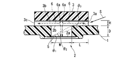
一方、本実施形態においては、通気防水膜と防護壁通気孔との間の通気通路が折曲されて折曲部を有するため、その通気通路が通気性を得る機能の他に、その通気通路を形成する壁面が浸入水に対する障壁としても機能する。具体例としては図1に示すように、筐体通気孔2の内側開口部2aと防護壁通気孔3a(および3c)との間の通気通路6の中央部に折曲部6aが形成されており、その通気通路6の壁面(例えば折曲部6a付近の面)、例えば図1に示すように防護壁3の内壁面,筐体通気孔2の内壁面(すなわち、筐体通気孔2の内側開口部2aよりも外側開口部2b側)および外側開口部2b縁面等が障壁として機能し、その障壁に対して浸入水Sが衝突し易く、その衝突した浸入水Sの水圧は減少することになる。そして、筐体通気孔2の内側開口部2aに取り付けられる通気防水膜5においては、浸入水Sの直接的な衝突や損傷等が抑制されることになる。
On the other hand, in this embodiment, since the ventilation passage between the ventilation waterproof membrane and the protective wall ventilation hole is bent and has a bent portion, in addition to the function of the ventilation passage to obtain air permeability, the ventilation passage wall surface to form a also functions as a barrier to immersion incoming water. As a specific example, as shown in FIG. 1, a
すなわち、図1のように筐体通気孔2の外側開口部2bを当該外側開口部2bとの間に間隙3bを設けて防護壁3を設けた構造の場合、筐体外周側から防護壁通気孔3aを介して通気通路6の筐体通気孔2内側に浸入水Sが浸入し得るが、通気通路6が折曲部6aによって折曲されているため、その通気通路6の壁面が侵入水に対する障壁として機能し易く、例えば筐体通気孔2や防護壁通気孔3等の形状を小さくしたり、それら筐体通気孔2と防護壁通気孔3との間の距離を必要以上に大きくしなくても、その浸入水Sの水圧を、折曲部6aを有する通気通路6の壁面によって減少させることできる。したがって、本実施形態の電子制御装置によれば、筐体の大型化を招くことなく十分な通気性が得られ易く、その通気性および防水性の両立を図ることも可能となる。
That is, in the case of the structure in which a
前記のように折曲部を有する通気通路が形成された構成であれば、筐体通気孔,防護壁等を含む電子制御装置の各種構成は種々の形態のもの適用することが可能である。 As long as the vent passage having the bent portion is formed as described above, various configurations of the electronic control device including the casing vent hole and the protective wall can be applied in various forms.
例えば筐体通気孔,間隙,防護壁通気孔の形状については、前記のように折曲された通気通路を形成できる構成であれば適宜設定することができる。具体例として、筐体通気孔,間隙の横断面形状や、筐体通気孔の内側および外側開口部の形状や、防護壁通気孔の形状について、真円,楕円,多角形等の形状に限定されるものではなく、種々の形状であっても良い。 For example, the shapes of the housing vent, the gap, and the protective wall vent can be appropriately set as long as the bent vent passage can be formed as described above. As specific examples, the cross-sectional shape of the housing vents and gaps, the inner and outer openings of the housing vents, and the shape of the protective wall vents are limited to shapes such as perfect circles, ellipses, and polygons. However, various shapes may be used.
また、浸入水は筐体外周側から防護壁通気孔を介して様々な角度で通気通路内に浸入し得るものであり、例えば直線状に侵入する浸入水の水圧は比較的高い場合があるため、このような高水圧の浸入水が通気通路の壁面に衝突し易くなるように、筐体通気孔,間隙,防護壁通気孔の形状を設定し、当該浸入水の水圧を低減することが好ましい。 Also, penetration water are those capable of entering immersed in the vent passage at different angles through the protective wall vent from the housing outer periphery, for example, water pressure of infiltration water entering the linearly be relatively high Therefore, such a high water pressure of immersion water inlet is so easily collides with the wall surface of the vent passage, the housing vent, gap, set the shape of the protective wall vent to reduce the pressure of the immersion water inlet preferable.
このように浸入水の水圧を低減する手法の一つとしては、例えば以下に示すように浸入水の浸入し得る角度等を定義して、前記の筐体通気孔等の形状を設定することが考えられる。まず、防護壁通気孔を介して通気通路の筐体通気孔内側に浸入する浸入水Sを投影線として仮想し、図1(後述する図6のX−X断面図に相当する概略図)に示すように投影線(すなわち浸入水)Sと筐体部材1(後述のカバー13に相当)の筐体通気孔2の内側開口部2aとがなす角をθ1、投影線Sから筐体通気孔2の内側開口部2aに対して直交した2つの垂直線と直交する方向の当該内側開口部2a開口幅をW、筐体通気孔2の軸心方向長さをD、WとDとの比D/Wをtanθ2とする。そして、前記tanθ1がtanθ2よりも小さくなるにつれて、直線状の浸入水Sは通気通路6の内壁に衝突し易くなることから、当該tanθ1が比較的小さくなるように(例えば関係式tanθ2>tanθ1を(以下、関係式αと称する)満たすように)、筐体通気孔2や防護壁3を設計する。
As one method of reducing the pressure of the thus-immersed incoming water, to define the angle, and the like that may penetrate the water inlet immersion, for example, as shown below, to set the shape of such the housing vent Conceivable. First, the intrusion water S that enters the inside of the housing vent of the vent passage through the protective wall vent is hypothesized as a projection line, and is shown in FIG. 1 (schematic diagram corresponding to an XX sectional view of FIG. 6 described later). As shown, the angle formed by the projection line (that is, the intrusion water) S and the
このように、浸入水の浸入し得る角度を想定して筐体通気孔,間隙,防護壁通気孔の形状を設定することにより、通気通路の壁面、すなわち防護壁3の内壁面,筐体通気孔2の内壁面(すなわち、筐体通気孔2の内側開口部2aよりも外側開口部2b側)および外側開口部2b縁面等が、浸入水Sに対する障壁として機能し易くなり、障壁に衝突した浸入水Sの水圧は減少することになる。そして、筐体通気孔2の内側開口部2aに取り付けられる通気防水膜5においては、浸入水Sの直接的な衝突が抑制されることになる。
Thus, immersion incoming water intruding may angle assumed housing vent, gap, by setting the shape of the protective wall vent wall vent passage, namely the inner wall surface of the
前記のような浸入水Sに係る角度θ1は、例えば電子制御装置の車体に対する取付位置や筐体(筐体部材1等)の形状,防護壁3の形状(防護壁通気孔3aや間隙3bの形状等),筐体通気孔2の位置等によって範囲が定められるものであり、その範囲で侵入水Sが防護壁通気孔3aを介して筐体通気孔2内側に浸入したとしても、tanθ1が比較的小さくなるように設計(例えば関係式αを満たすように設計)された形状の筐体通気孔2,防護壁3を備えていれば良いため、筐体通気孔,防護壁通気孔等の形状を必要以上に小さくしたり、それら筐体通気孔と防護壁通気孔との間の距離を必要以上に大きくすることなく、前記のように通気防水膜5に対する浸入水Sの直接的な衝突を抑制できる。
The angle θ 1 related to the intruding water S is, for example, the mounting position of the electronic control device with respect to the vehicle body, the shape of the housing (
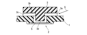
また、例えば前記横断面形状が楕円等の筐体通気孔のように、その横断面方向によって内側開口部の開口幅が異なる場合(例えば楕円の短径や長径がある場合)には、最も短い開口幅が前記関係式αに係るWとなるように当該筐体通気孔を形成(横断面楕円の場合には短径がWとなるように形成)することにより、tanθ1を小さくし易くなる(例えば関係式αを満たすことがより容易となる)。さらに、図2(後述する図6のX−X断面図に相当する概略)に示すように筐体通気孔2の外側開口部2b(または内側開口部2a)の縁面に対し突起2cを設けた場合においても、tanθ1を小さくし易くなる(関係式αを満たすことがより容易となる)。
In addition, for example, when the opening width of the inner opening differs depending on the direction of the cross section, such as a housing vent having an oval cross section (for example, when the ellipse has a minor axis or a major axis), it is the shortest. By forming the housing vent so that the opening width is W according to the relational expression α (when the cross section is elliptical, the tan θ 1 is easily reduced). (For example, it becomes easier to satisfy the relational expression α). Further, as shown in FIG. 2 (an outline corresponding to an XX sectional view of FIG. 6 to be described later), a
防護壁においても、筐体通気孔との間隙や筐体通気孔の形状等を適宜設定できるが、防護壁内に突起、例えば図3(後述する図6のX−X断面図に相当する概略)に示すように防護壁3内壁面における筐体通気孔2に対向した位置から筐体通気孔2方向に突出した突起部3dを設けた場合には、その突起部3dが浸入水Sに対する障壁として機能し、筐体通気孔2に対する浸入水Sの直接的な衝突がより抑制されることになる。
Also in the protective wall, the gap with the housing vent, the shape of the housing vent, and the like can be set as appropriate. However, a protrusion in the protective wall, for example, a schematic view corresponding to FIG. in the case where the protruding
また、例えば図1に示すように筐体通気孔2と防護壁通気孔3aとの間の距離をL、防護壁通気孔3aの開口幅(高さ等)をH、LとHとの比H/Lをtanθ3として、このtanθ3が比較的小さくなるよう(例えば関係式tanθ1>tanθ3(以下、関係式βと称する)を満たすように)設計された筐体通気孔2と防護壁3とを適用した場合には、防護壁3の内壁面,外側開口部2b縁面等が、浸入水Sに対する障壁として機能し当該浸入水Sの水圧を減少することになり、その結果、通気防水膜5に対する浸入水Sの直接的な衝突がより抑制されることになる。
Further, for example, the distance between the
さらに、防護壁3は、単に1個の防護壁通気孔3aだけでなく複数個の通気孔、例えば図1〜図3に示すように防護壁通気孔3a,3cを形成しても良い。このように複数個の防護壁通気孔3a,3cを形成することにより、筐体通気孔2内,防護壁3内等の内圧を低減し易くなり、折曲部を有する通気通路において通気性の向上を図ることができる。
Furthermore, the
また、筐体通気孔2,防護壁3内壁面,防護壁通気孔3a,3cにおける角部を適宜面取りしてテーパー状にすることにより、例えば浸入水S(障壁によって水圧が低減された侵入水)等による溜り水が筐体通気孔2内等に溜まった場合に、その溜り水が筐体通気孔2内等から外部へ排出し易くなる。さらに、筐体通気孔2の横断面方向が水平方向(電子制御装置の取り付け位置に応じた水平方向)に対して所定角度を有する場合には、たとえ侵入水Sが筐体通気孔2内に溜り得る状態であっても、その筐体通気孔2内が満水にはならないように抑制され、溜り水の排出がより促されることになる。
In addition, by appropriately chamfering the corners of the
筐体部材や防護壁に適用する材料は、折曲部を有する通気通路を形成できるものであれば特に限定されるものではなく、例えば前記のように関係式αや関係式βを満たすように筐体通気孔や防護壁通気孔を形成できるものが挙げられる。例えば樹脂材料を用いた樹脂成形や、金属材料(アルミニウム,鉄等)を型成形法,鋳造法(ダイカスト等)により、所望の形状に一体成形して成るものが挙げられる。また、筐体部材の表面からの熱放射率を高める目的で、例えば筐体部材等の表面に薄膜の絶縁処理(例えば、アルマイト等の表面処理,カチオン電着等の塗装処理)を施しても良い。 The material applied to the casing member and the protective wall is not particularly limited as long as it can form a ventilation passage having a bent portion, and for example, satisfies the relational expression α and the relational expression β as described above. The thing which can form a housing | casing ventilation hole and a protective wall ventilation hole is mentioned. For example, resin molding using a resin material, or a metal material (aluminum, iron, etc.) integrally molded into a desired shape by a mold molding method or a casting method (die casting, etc.) can be mentioned. In addition, for the purpose of increasing the thermal emissivity from the surface of the casing member, for example, the surface of the casing member or the like may be subjected to a thin film insulation treatment (for example, a surface treatment such as anodized or a coating treatment such as cationic electrodeposition). good.
<実施例>
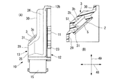
以下に、本実施形態に係る電子制御装置を、自動車のエンジンコントロールユニットに適用した一例について、図面に基づいて詳細に説明する。先ず、図4〜図6を参照して、複数の筐体部材(後述するケース12,カバー13等)を接合して成る筐体内部の空間に回路基板4を収容した電子制御装置10の基本構成について説明する。なお、ここでの説明においては、便宜上、図4の上下方向、つまり回路基板4の肉厚方向を装置10自体の上下方向として説明することがあるが、これは、車載状態での鉛直方向に必ずしも対応するものではなく、例えば車両搭載状態が縦置き姿勢の場合、図4の装置10の上下方向が自動車の前後方向に沿うものとなる。
<Example>
Hereinafter, an example in which the electronic control device according to the present embodiment is applied to an engine control unit of an automobile will be described in detail based on the drawings. First, with reference to FIG. 4 to FIG. 6, the basics of the
この電子制御装置10は、車体側に取り付けられる略板状のケース12と略箱状のカバー13とを液密に接合(シール材を介して接合)してなる筐体と、この筐体内部の保護空間に収容され各種電子部品を実装した回路基板4と、により大略構成されており、図示していないが、エンジンルーム等に搭載され、車体側への取付面となるケース12のブラケット23,24の底面において、車体側に取り付けられるものである。なお、車体側への取付面は、この実施形態ではケース12の底面と平行に構成されているが、車体側への取付部(ブラケット23,24)の形状等によってはケース12の底面に対して傾斜する場合もある。
The
各構成要素について具体的に説明すると、回路基板4は、その上方側面(カバー13側の面)4aには、コンデンサ,コイル等のような、比較的発熱しない、もしくは例えばヒートシンク等の特段の放熱処置を必要としない非発熱性部品6が実装され、下方側面(ケース12側の面)4bには演算処理装置,トランジスタ,IC等の比較的発熱し易い発熱性部品3が実装された、いわゆるプリント配線基板であり、例えばガラスエポキシ樹脂等からなる板材の表裏面あるいはその内部に配線回路パターンが形成され、この配線回路パターンに発熱性部品3,非発熱性部品6が半田等によりそれぞれ電気的に接続されている。
Specifically, each component will be described. The
また、回路基板4の周縁側の一部には、外部のコネクタとそれぞれ接続される2つの第1,第2接続口16,17を有するコネクタ15が取り付けられている。このコネクタ15は、その接続先に応じて2つに分割された各接続口16,17が取付基部15aを介して一体化されたものであって、この取付基部15aを介して回路基板4に固定(例えば複数のビス等により固定)されている。このコネクタ15は、取付基部15aによって連結された一連の接続口16,17が、ケース12とカバー13との間に形成される空間である窓部13aを介して外部へと臨むようになっていて、ここにおいて車両側のコネクタと接続される。
A
コネクタ15には、回路基板4上の配線回路パターンに電気的に接続された複数の雄型端子16a,17aが設けられており、これらの雄型端子16a,17aが図外のコネクタに収容される複数の雌型端子と接続されることで、当該図外のコネクタ(雌型端子)に接続されるセンサー類やポンプ等の所定の機器と電気的に接続されることとなる。
The
ケース12は、アルミニウム等の熱伝導性に優れた金属材料によって略板状、より詳しくは周縁がわずかに立ち上がる浅い箱状に一体形成されたものである。具体的には、ほぼ矩形状の底壁12aの外周縁(各側辺)に側壁12bが立設され、全体が上方へ開口するように構成されている。側壁12bの四隅には、カバー13を取付固定するためのカバー固定部28が形成され、これら各カバー固定部28には上下方向に貫通する貫通孔28aが設けられている。
The
回路基板11の取付固定は、ケース12の底壁12aの内壁面側の周縁部に立設された基板固定部19を介して行われる。この基板固定部19は、その上端部に、回路基板4を支持する平坦状の支持面が構成されていて、これら各支持面には、回路基板4の固定に供する図外のビスが螺合する雌ねじ穴19aが形成されている。ビスが各雌ねじ穴19aに螺着されることによって、回路基板4が各基板固定部19に支持された状態でケース12に固定されることとなる。
The mounting and fixing of the
また、ケース12における側壁12bの外側部には、電子制御装置10の車体(図示省略)への取付に供する一対のブラケット23,24が一体に設けられている。これらブラケット23,24には、上下方向に貫通する貫通孔23a,側方に開口する切欠溝24aがそれぞれ設けられていて、これら貫通孔23a,切欠溝24aを挿通するボルト等によって、車体側への取付が行われる。さらに、図5に示すように、ケース12における底壁12aの裏面側には、短冊状の放熱フィン12cが複数個それぞれ所定間隔を隔てて並列に設けられている。
A pair of
カバー13は、金属材料に比べて軽量かつ低コストで所定の合成樹脂材料によって略箱状に一体成形されたものであり、回路基板4及びコネクタ15の上方を覆う上壁部25と、上記の窓部13aを除く上壁部25の周縁の三方を囲う側壁26と、を有している。側壁26におけるケース12のカバー固定部28と対向する位置には、カバー固定部28の貫通孔28aに対して貫装可能な形状の位置決め突部27aが形成され、それら各位置決め突部27aがそれぞれ貫通孔28aに貫装されることによって、カバー13が各カバー固定部28に支持された状態でケース12に固定されることとなる。
The
ケース12の上側の周縁部とカバー13の下側の周縁部との接合部分、ケース12の上側の周縁部とコネクタ15の下側の周縁部との接合部分、更にはコネクタ15の外周部と窓部13aの内周縁部との接合部分は、それぞれ、防水性を確保するために、シール剤を介して液密に接合されている。詳しくは図示していないが、これらの接合部分には、その一方にシール溝を形成したり、他方に突条を設けておき、この突条をシール溝に隙間をもって入り込むようにすることで、シール溝と突条との隙間に充填されるシール剤の長さ、いわゆるシール長を十分に確保して、所期のシール性が得られるように構成することができる。ここで、シール剤としては、流動性を有するシール剤であれば特に具体的な構成は限定されるものではなく、例えばエポキシ系やシリコーン系、アクリル系など、電子制御装置10の仕様や要求に応じて適宜に選択することができる。
A joint portion between the upper peripheral portion of the
前述したように、この装置10においては、回路基板4の一端に、側方へ開口するコネクタ15が取り付けられた構造となっている。この関係で、カバー13は、基板の肉厚方向の寸法(高さ)が異なる回路基板4とコネクタ15のそれぞれに応じた段付形状をなしている。具体的には、回路基板4及びコネクタ15を挟んでケース12と対向するカバーの上壁部25には、ケース12の取付面11に平行な上段部29と下段部30とが設けられている。コネクタ15の上方を覆う上段部29は、回路基板4の上方を覆う下段部30に対して、基板厚さ方向の寸法が大きく設定されている。そして、このように高さの異なる上段部29と下段部30とを滑らかに繋ぐ傾斜壁部31が設けられている。この傾斜壁部31は、ケース12の底壁12aに対して所定の傾斜角度、例えば約45度の傾斜角度で平坦に傾斜しており、従って、上段部29や下段部30に対しても同じ傾斜角度で傾斜している。また、傾斜壁部31には、いわゆる呼吸フィルタを形成する目的で、肉厚方向に貫通して形成される筐体通気孔2を保護するために、防護壁3が設けられる。筐体通気孔2は、防水性及び通気性の双方を併せ持つゴアテックス(登録商標)などの薄膜状の通気防水膜(図示省略)が取り付けられたものであって、防護壁3により、例えば洗車時等に高温・高圧の水が通気防水膜へ直接吹き付けられないように保護される。
As described above, the
防護壁3は、筐体通気孔2への通気が可能なように、図1〜図3に示したような所定の間隙3bを隔てて筐体通気孔2の外側開口部2bの周囲を覆うように設けられ、その間隙3bと連通している防護壁通気孔3a,3cが設けられている。間隙3bを形成するための防護壁3の内壁面は、例えば洗車水等による浸入水Sから通気防水膜5を効果的に保護するように、この通気防水膜5が取り付けられる筐体通気孔2よりも大きな面積・寸法に設定されている。この防護壁3の間隙3b,防護壁通気孔3a,3cにより、筐体通気孔2への通気を可能とする一連の通気通路を構成するとともに、後述するように、筐体通気孔2に溜まった浸入水S等による溜り水S1等を排水する排水通路としても機能するものである。
The
ここで、このような電子制御装置10の一般的な車載搭載姿勢としては、多くの場合、図7((B)は図6のY−Y断面図に相当する概略図)に示すように取付面11をほぼ鉛直方向49とする縦置き姿勢と、図8((B)は図6のY−Y断面図に相当する概略図)に示すように取付面11をほぼ水平方向48とする横置き姿勢と、のいずれかである。本発明者等はこの点に着目し、筐体の平坦な車体側への取付面11に対し、通気防水膜5が所定角度で傾斜するように、筐体通気孔2を、筐体の外壁のうちで、車体側への取付面11に対して傾斜する傾斜壁部31に設けている。
Here, as a general on-vehicle mounting posture of such an
これによって、図7,図8に示すように、縦置き姿勢及び横置き姿勢のいずれの搭載姿勢においても、通気防水膜5が水平面(図7、図8の左右方向)に対して傾斜する姿勢となるために、仮に筐体通気孔2に浸入水S等による溜り水S1が溜まっても、満水前の時点(ある程度の溜り水S1が溜まった時点)で、溜り水S1の一部(水面)が傾斜する筐体通気孔2の上端に達し、間隙3bを介して外部へ排水されることとなり、それ以上、溜り水S1が溜まることを抑制できる。従って、浸入水S等により通気防水膜5が閉塞されることは抑制され、簡素な構造でありながら、通気防水膜5による所期の通気性・呼吸性を確保して、信頼性・耐久性を向上することができる。
As a result, as shown in FIGS. 7 and 8, the ventilation
取付面11に対する通気防水膜5の傾斜角度は、例えば45度、あるいは45度を中心とする所定の範囲、具体的には30〜60度程度の傾斜角度に設定することが挙げられる。これによって、縦置き姿勢及び横置き姿勢のいずれの搭載姿勢においても、水平面に対して45度程度の十分な傾斜角度を確保することができ、搭載姿勢にかかわらず通気防水膜5による通気性・呼吸性を確保することが可能となる。
The inclination angle of the breathable
更に、通気防水膜5が閉塞される事態をより効果的に回避するように、筐体通気孔2等の寸法や形状においては、関係式αや関係式βを満たすようにすることが前提であるが、例えば筐体通気孔2の直径(径方向寸法)が、筐体通気孔2の深さ(軸方向寸法)に比して、十分に大きく設定(例えば2倍以上に設定)することが挙げられる。
Furthermore, in order to more effectively avoid the situation where the ventilation
また、筐体通気孔2内において突起部を形成、例えば図9に示すように筐体通気孔2内の外側開口部2b付近に突起部2cを形成することにより、内側開口部2a等よりも外側開口部2bの径方向寸法を小さくしても良い。このような構成によれば、筐体通気孔2内に対する浸入水Sの浸入を抑制することができる。さらに、前記の突起部2cにおいて、図10に示すように筐体通気孔2内に連通(例えば筐体通気孔2と同じ貫通方向に貫通して連通)した貫通孔2dを形成することにより、例えば筐体通気孔2に溜った溜り水(図7,図8の溜り水S1に相当)が排水され易くなる。なお、貫通孔2dにおいては、突起部2cに対して適宜形成できるものであるが、例えば防護壁通気孔3aや3cから距離を隔てた位置に形成することが好ましい。
Further, a projection is formed in the
防護壁3においては、防護壁通気孔3a,3cの開口形状を台形状,真円状,楕円状,半円状等の各種形状にしても良いが、例えば図11,図12(それぞれ図6のZ方向からの概略断面図)に示すように、防護壁通気孔3c内側に突出する突出部3eが形成されたものを適用しても良く、浸入水Sの浸入をより抑制することが可能となる。また、装置10において浸入水Sの障壁として機能する部位がある場合、例えば図6に示すように浸入水Sがカバー13の角部に衝突し得る場合には、その衝突した方向からの浸入水Sが防護壁3付近に到達することは抑制されるため、例えば図13(防護壁3の上方側からの概略図)に示すように防護壁3の外壁形状等を縮小(図13では二点鎖線部を省略して台形状に縮小)し、筐体通気孔2と防護壁通気孔3a,3cとの距離を短くて筐体通気孔2内,防護壁3内等の内圧を低減し易くしたり、当該筐体通気孔2の位置をコネクタ15側にオフセットすることにより、通気性の向上を図ることができる。
In the
筐体通気孔2や防護壁3を、仮にカバー13の上段部29や側壁部26に設けた場合、この防護壁3が装置10から上方あるいは側方へ部分的に張り出す形となり、装置全体の高さ方向寸法や幅方向寸法の増加を招いたり、エンジンルーム内の他の部品と干渉するなどの車両搭載性の低下を招くおそれがあるが、本実施例のように防護壁3を傾斜壁部31に設けた場合には、防護壁3が、装置全体の寸法に影響のない傾斜壁部31の斜め前方のスペースに膨出する形となり、その防護壁3を設けたことに伴う装置の大型化等を招くことを抑制でき、車両搭載性を高めることが可能となる。
If the
また、本実施例のように、所定厚さを有するコネクタ15が側方に表出する形態の電子制御装置10にあっては、コネクタ15と回路基板4との厚さの相違に応じてカバー13が段付形状、すなわちカバー13の上壁部25には、高さの異なる上段部29と下段部30とが取付面11に平行に設けられ、詳しくは、厚肉なコネクタ15を覆う上段部29が、薄肉な回路基板4を覆う下段部30に比して、基板厚さ方向の寸法が大きく設定されている。従って、高さの異なる上段部29と下段部30とを繋ぐ部分を傾斜壁部31として、この傾斜壁部31に筐体通気孔2を形成すればよく、敢えて傾斜壁部31を別途設ける必要がないために、本発明の適用が極めて容易である。しかも、傾斜壁部31を上段部29や下段部30に対して傾斜させているために、例えば上段部29と下段部30とを垂直な壁部により繋ぐ構造に比して、上段部29及び下段部30と傾斜壁部31との接続部分(エッジ部分)の傾斜・湾曲角度が緩やかなものとなり、この部分への応力集中を緩和することができる。
Further, in the
以上、本発明において、記載された具体例に対してのみ詳細に説明したが、本発明の技術思想の範囲で多彩な変更等が可能であることは、当業者にとって明白なことであり、このような変更等が特許請求の範囲に属することは当然のことである。 Although the present invention has been described in detail only for the specific examples described above, it is obvious to those skilled in the art that various modifications can be made within the scope of the technical idea of the present invention. It is natural that such changes and the like belong to the scope of the claims.
1…筐体部材
2…筐体通気孔
2a,2b…開口部
3…防護壁
3a,3c…防護壁通気孔
3b…間隙
5…通気防水膜
6…通気通路
6a…折曲部
DESCRIPTION OF
Claims (4)
前記回路基板を内部空間に収容する筐体部材と、
該筐体部材の外壁のうち少なくとも一部が前記筐体部材の車体取付け面に対し傾斜して形成された傾斜壁部と、
該傾斜壁部の厚さ方向に貫通した筐体通気孔と、
前記筐体通気孔の外側開口部を覆う防護壁と、
前記筐体通気孔の内側開口部に設けられ、前記車体取付け部の取付け面に対して傾斜する通気防水膜と、
前記防護壁に形成されて、前記筐体部材の外部に連通する防護壁通気孔と、
前記防護壁通気孔から前記防護壁内に直線状に形成されるとともに、前記筐体通気孔と連通する間隙と、を有し、
前記筐体通気孔の内側開口部と前記防護壁通気孔とを結ぶ仮想線上に、前記間隙または前記筐体通気孔の内壁面が位置するように前記間隙と前記筐体通気孔とが連通していることを特徴とする電子制御装置。 A circuit board on which electronic components are mounted;
A housing member for accommodating the circuit board in an internal space ;
An inclined wall portion formed such that at least a part of the outer wall of the housing member is inclined with respect to the vehicle body mounting surface of the housing member ;
A housing vent penetrating in the thickness direction of the inclined wall ;
A protective wall covering the outer opening of the housing vent;
A ventilation waterproof film provided at an inner opening of the housing ventilation hole and inclined with respect to an attachment surface of the vehicle body attachment part ;
A protective wall ventilation hole formed in the protective wall and communicating with the outside of the housing member ;
A straight line is formed in the protective wall from the protective wall ventilation hole , and has a gap communicating with the housing ventilation hole ,
The gap and the casing vent hole communicate with each other so that the gap or the inner wall surface of the casing vent hole is positioned on a virtual line connecting the inner opening of the casing vent hole and the protective wall vent hole. An electronic control device characterized by that .
前記防護壁通気孔は、少なくとも一対からなり、前記防護壁に互いに対向して開口し、The protective wall ventilation hole is composed of at least a pair, and opens to the protective wall so as to face each other.
前記間隙は、前記両防護壁通気孔の間を直線状に連通していると共に、筐体通気孔と連通していることを特徴とする請求項1に記載の電子制御装置。2. The electronic control device according to claim 1, wherein the gap communicates between the protective wall vent holes in a straight line and communicates with the housing vent hole.
前記防護壁通気孔が、前記傾斜壁部に開口していることを特徴とする請求項1に記載の電子制御装置。The electronic control device according to claim 1, wherein the protective wall ventilation hole opens in the inclined wall portion.
Priority Applications (5)
| Application Number | Priority Date | Filing Date | Title |
|---|---|---|---|
| JP2012215343A JP6105887B2 (en) | 2012-09-28 | 2012-09-28 | Electronic control unit |
| PCT/JP2013/074679 WO2014050591A1 (en) | 2012-09-28 | 2013-09-12 | Electronic control device |
| CN201380040195.6A CN104509226B (en) | 2012-09-28 | 2013-09-12 | Electronic-controlled installation |
| US14/424,675 US9781849B2 (en) | 2012-09-28 | 2013-09-12 | Electronic control device |
| DE112013004771.3T DE112013004771B4 (en) | 2012-09-28 | 2013-09-12 | Electronic control device |
Applications Claiming Priority (1)
| Application Number | Priority Date | Filing Date | Title |
|---|---|---|---|
| JP2012215343A JP6105887B2 (en) | 2012-09-28 | 2012-09-28 | Electronic control unit |
Publications (3)
| Publication Number | Publication Date |
|---|---|
| JP2014072257A JP2014072257A (en) | 2014-04-21 |
| JP2014072257A5 JP2014072257A5 (en) | 2015-03-12 |
| JP6105887B2 true JP6105887B2 (en) | 2017-03-29 |
Family
ID=50387998
Family Applications (1)
| Application Number | Title | Priority Date | Filing Date |
|---|---|---|---|
| JP2012215343A Active JP6105887B2 (en) | 2012-09-28 | 2012-09-28 | Electronic control unit |
Country Status (5)
| Country | Link |
|---|---|
| US (1) | US9781849B2 (en) |
| JP (1) | JP6105887B2 (en) |
| CN (1) | CN104509226B (en) |
| DE (1) | DE112013004771B4 (en) |
| WO (1) | WO2014050591A1 (en) |
Families Citing this family (45)
| Publication number | Priority date | Publication date | Assignee | Title |
|---|---|---|---|---|
| WO2015182131A1 (en) * | 2014-05-28 | 2015-12-03 | 日東電工株式会社 | Metal case and ventilation structure using same |
| JP5995113B2 (en) * | 2014-07-02 | 2016-09-21 | 株式会社オートネットワーク技術研究所 | Electrical junction box |
| JP6346048B2 (en) * | 2014-09-18 | 2018-06-20 | 日立オートモティブシステムズ株式会社 | Electronic control unit |
| JP6330679B2 (en) * | 2015-02-05 | 2018-05-30 | 株式会社デンソー | Electronic equipment |
| US9938885B2 (en) * | 2015-02-26 | 2018-04-10 | GM Global Technology Operations LLC | Manifold for an engine assembly |
| JP6485257B2 (en) * | 2015-07-01 | 2019-03-20 | 富士電機株式会社 | Semiconductor device and manufacturing method of semiconductor device |
| US9769951B2 (en) * | 2015-07-08 | 2017-09-19 | Autoliv Asp, Inc. | Automotive radar system and automotive radar sensor module with breather structure |
| DE102015214923B4 (en) * | 2015-08-05 | 2019-02-14 | Continental Automotive Gmbh | Pressure compensation element and housing with such |
| DE102015011824A1 (en) * | 2015-09-09 | 2017-03-09 | GM Global Technology Operations LLC (n. d. Gesetzen des Staates Delaware) | A protective cover for an electronic device in a vehicle, boot assembly for a vehicle and vehicle with the boot assembly |
| CN105163544A (en) * | 2015-09-22 | 2015-12-16 | 武汉菱电汽车电控系统股份有限公司 | Multifunctional automobile electronic control unit packaging box |
| JP6113314B1 (en) * | 2016-02-01 | 2017-04-12 | 三菱電機株式会社 | Waterproof control device |
| JP6072948B1 (en) * | 2016-02-01 | 2017-02-01 | 三菱電機株式会社 | Waterproof control device |
| JP6072947B1 (en) * | 2016-02-01 | 2017-02-01 | 三菱電機株式会社 | Waterproof control device |
| JP6129370B1 (en) * | 2016-02-15 | 2017-05-17 | 三菱電機株式会社 | Waterproof electronic device unit |
| US10021803B2 (en) * | 2016-02-26 | 2018-07-10 | Delta Electronics, Inc. | Power supply |
| JP6356725B2 (en) * | 2016-05-19 | 2018-07-11 | ファナック株式会社 | Electronics |
| EP3250014B1 (en) | 2016-05-24 | 2019-12-18 | Veoneer Sweden AB | A housing for electronic components |
| JP6611010B2 (en) * | 2016-06-02 | 2019-11-27 | 株式会社オートネットワーク技術研究所 | Board unit |
| CN110087851B (en) * | 2016-12-22 | 2024-04-12 | 日立安斯泰莫株式会社 | Electronic control device |
| JP6881045B2 (en) * | 2017-06-05 | 2021-06-02 | 株式会社デンソー | Electronic device |
| CN108128133A (en) * | 2017-12-25 | 2018-06-08 | 福建德驰新能源科技有限公司 | A kind of electronic automobile-used battery-mounting device |
| JP6573336B2 (en) * | 2018-01-11 | 2019-09-11 | Necプラットフォームズ株式会社 | Waterproof structure, casing and electronic device for ventilation opening of electronic device |
| JP7090426B2 (en) * | 2018-01-24 | 2022-06-24 | 株式会社トランストロン | Electronic device |
| JP7114918B2 (en) * | 2018-02-06 | 2022-08-09 | 株式会社デンソー | electronic controller |
| DE102018103747A1 (en) * | 2018-02-20 | 2019-08-22 | Volkswagen Ag | Device with a pressure compensation element and method for producing a component of the device |
| US11056864B2 (en) * | 2018-02-23 | 2021-07-06 | Sumitomo Wiring Systems, Ltd. | Electrical junction box |
| CN108876979A (en) * | 2018-04-26 | 2018-11-23 | 南安市创培电子科技有限公司 | A kind of access control equipment with fingerprint recognition alternative |
| JP6640914B2 (en) * | 2018-05-24 | 2020-02-05 | 日立オートモティブシステムズ株式会社 | Electronic control unit |
| CN108617118A (en) * | 2018-07-12 | 2018-10-02 | 合肥晟泰克汽车电子股份有限公司 | The waterproof radiating structure of vehicle electronic device |
| JP2020023295A (en) * | 2018-08-08 | 2020-02-13 | 日本電産モビリティ株式会社 | Submergence detection device, vehicle control device, and vehicle |
| JP7235455B2 (en) * | 2018-08-13 | 2023-03-08 | Kyb株式会社 | Electronic equipment and its manufacturing method |
| CN112690045B (en) * | 2018-09-21 | 2022-09-27 | 三菱电机株式会社 | Ventilating mechanism of electronic equipment shell |
| IT201800010847A1 (en) * | 2018-12-06 | 2020-06-06 | Zammitek S R L | Device for locking the sockets of a vehicle engine control unit |
| DE102019201103A1 (en) | 2019-01-29 | 2020-07-30 | Lufthansa Technik Aktiengesellschaft | Attachment housing for attachment to an aircraft |
| DE102019104729A1 (en) * | 2019-02-25 | 2020-08-27 | Nidec Gpm Gmbh | Pump unit having a connector with sintered filter for pressure equalization |
| DE102019104728A1 (en) * | 2019-02-25 | 2020-08-27 | Nidec Gpm Gmbh | Pump unit comprising a plug connector with pressure compensation element |
| DE102019104727A1 (en) * | 2019-02-25 | 2020-08-27 | Nidec Gpm Gmbh | Pump unit comprising a plug connector with pressure compensation element |
| US11525709B2 (en) | 2019-04-11 | 2022-12-13 | Veoneer Us, Llc | Electronic unit with vent integrated with terminal aperture |
| JP7140076B2 (en) * | 2019-08-30 | 2022-09-21 | 株式会社オートネットワーク技術研究所 | connector |
| JP7264002B2 (en) * | 2019-09-30 | 2023-04-25 | 住友電装株式会社 | electric junction box |
| JP2021092657A (en) * | 2019-12-10 | 2021-06-17 | 住友電気工業株式会社 | Optical transceiver |
| DE102021205284A1 (en) | 2021-05-25 | 2022-12-01 | Zf Friedrichshafen Ag | Housing for electronic components and control unit |
| JP7414774B2 (en) | 2021-06-28 | 2024-01-16 | 矢崎総業株式会社 | Resin molded body, method for manufacturing resin molded body, and hydraulic pressure control device |
| CN113556922A (en) * | 2021-07-01 | 2021-10-26 | 南京瑞米电气有限公司 | Heat radiation structure of instrument case |
| US20240010209A1 (en) * | 2022-07-06 | 2024-01-11 | Gm Cruise Holdings Llc | Environmental and electromagnetic seal for autonomous vehicle control systems |
Family Cites Families (16)
| Publication number | Priority date | Publication date | Assignee | Title |
|---|---|---|---|---|
| JPH01173982U (en) * | 1988-05-25 | 1989-12-11 | ||
| JPH1187944A (en) * | 1997-09-09 | 1999-03-30 | Yokogawa Electric Corp | Waterproof dust-preventive breathing case |
| JP2000294954A (en) * | 1999-04-05 | 2000-10-20 | Nec Eng Ltd | Breathing hole structure for chassis of outdoor apparatus |
| JP2004266211A (en) * | 2003-03-04 | 2004-09-24 | Nitto Denko Corp | Ventilation material and ventilation case using this |
| JP2006005162A (en) * | 2004-06-17 | 2006-01-05 | Denso Corp | Waterproof case for electronic equipment |
| ATE411586T1 (en) | 2004-08-23 | 2008-10-15 | Schreiner Group Gmbh & Co Kg | LABEL TO COVER GAS EXCHANGE OPENINGS |
| DE102004056662A1 (en) * | 2004-11-24 | 2006-06-01 | Robert Bosch Gmbh | Electric device |
| JP2006196596A (en) * | 2005-01-12 | 2006-07-27 | Denso Corp | Water repellent filter attaching structure and electronic apparatus provided with water repellent filter |
| EP1799021B1 (en) | 2005-12-14 | 2012-06-06 | Denso Corporation | Waterproof case |
| EP2006160B1 (en) * | 2007-05-21 | 2009-12-16 | Magneti Marelli S.p.A. | Electronic control unit with expanded blocks |
| JP5147782B2 (en) * | 2009-05-26 | 2013-02-20 | 古野電気株式会社 | Housing case, fluid flow velocity reduction structure, and marine electronic equipment |
| JP5434669B2 (en) * | 2010-02-26 | 2014-03-05 | 株式会社デンソー | Waterproof housing and waterproof device |
| DE102011012673A1 (en) * | 2010-03-17 | 2011-09-22 | Hitachi Automotive Systems, Ltd. | Electronic control device for vehicles |
| CN202143347U (en) * | 2011-07-27 | 2012-02-08 | 常州市泛亚微透科技有限公司 | Electromagnetic compatible (EMC) waterproof ventilating bolt |
| JP5792603B2 (en) * | 2011-11-28 | 2015-10-14 | 日東電工株式会社 | Ventilation member |
| JP2013197405A (en) * | 2012-03-21 | 2013-09-30 | Hitachi Automotive Systems Ltd | Electronic control device |
-
2012
- 2012-09-28 JP JP2012215343A patent/JP6105887B2/en active Active
-
2013
- 2013-09-12 DE DE112013004771.3T patent/DE112013004771B4/en active Active
- 2013-09-12 US US14/424,675 patent/US9781849B2/en active Active
- 2013-09-12 CN CN201380040195.6A patent/CN104509226B/en active Active
- 2013-09-12 WO PCT/JP2013/074679 patent/WO2014050591A1/en active Application Filing
Also Published As
| Publication number | Publication date |
|---|---|
| DE112013004771T5 (en) | 2015-06-03 |
| US20150208525A1 (en) | 2015-07-23 |
| JP2014072257A (en) | 2014-04-21 |
| WO2014050591A1 (en) | 2014-04-03 |
| DE112013004771B4 (en) | 2022-08-11 |
| CN104509226A (en) | 2015-04-08 |
| US9781849B2 (en) | 2017-10-03 |
| CN104509226B (en) | 2018-02-13 |
Similar Documents
| Publication | Publication Date | Title |
|---|---|---|
| JP6105887B2 (en) | Electronic control unit | |
| JP5543948B2 (en) | Electronic controller seal structure | |
| JP5905800B2 (en) | Electronic controller seal structure | |
| JP5358639B2 (en) | Electronic controller seal structure | |
| US9277681B2 (en) | Electronic control apparatus | |
| JP6023524B2 (en) | Electronic control unit | |
| JP2014063930A (en) | Electronic controller | |
| JP5526096B2 (en) | Electronic controller seal structure | |
| JP6423552B2 (en) | Electronic control unit | |
| JP2013069736A (en) | Electronic control device | |
| JP2014209639A (en) | Electronic control device | |
| JP2008061400A (en) | Drainage structure of electric connection box | |
| JP2010052701A (en) | Electronic control device | |
| JP6346048B2 (en) | Electronic control unit | |
| JP2017139056A (en) | Waterproof type controller | |
| JP6419125B2 (en) | Electronic control unit | |
| JP6640914B2 (en) | Electronic control unit | |
| JP7142788B2 (en) | electrical equipment | |
| JP7019828B2 (en) | Ventilation mechanism of electronic device housing | |
| JP2013197404A (en) | Electronic controller | |
| JP6109124B2 (en) | Housing for vehicle mounting | |
| JP2013140865A (en) | Housing and electronic control device |
Legal Events
| Date | Code | Title | Description |
|---|---|---|---|
| A521 | Request for written amendment filed |
Free format text: JAPANESE INTERMEDIATE CODE: A523 Effective date: 20150127 |
|
| A621 | Written request for application examination |
Free format text: JAPANESE INTERMEDIATE CODE: A621 Effective date: 20150127 |
|
| A131 | Notification of reasons for refusal |
Free format text: JAPANESE INTERMEDIATE CODE: A131 Effective date: 20150811 |
|
| A521 | Request for written amendment filed |
Free format text: JAPANESE INTERMEDIATE CODE: A523 Effective date: 20151008 |
|
| A131 | Notification of reasons for refusal |
Free format text: JAPANESE INTERMEDIATE CODE: A131 Effective date: 20160301 |
|
| A521 | Request for written amendment filed |
Free format text: JAPANESE INTERMEDIATE CODE: A523 Effective date: 20160425 |
|
| A131 | Notification of reasons for refusal |
Free format text: JAPANESE INTERMEDIATE CODE: A131 Effective date: 20160920 |
|
| A521 | Request for written amendment filed |
Free format text: JAPANESE INTERMEDIATE CODE: A523 Effective date: 20161108 |
|
| TRDD | Decision of grant or rejection written | ||
| A01 | Written decision to grant a patent or to grant a registration (utility model) |
Free format text: JAPANESE INTERMEDIATE CODE: A01 Effective date: 20170221 |
|
| A61 | First payment of annual fees (during grant procedure) |
Free format text: JAPANESE INTERMEDIATE CODE: A61 Effective date: 20170303 |
|
| R150 | Certificate of patent or registration of utility model |
Ref document number: 6105887 Country of ref document: JP Free format text: JAPANESE INTERMEDIATE CODE: R150 |
|
| R250 | Receipt of annual fees |
Free format text: JAPANESE INTERMEDIATE CODE: R250 |
|
| R250 | Receipt of annual fees |
Free format text: JAPANESE INTERMEDIATE CODE: R250 |
|
| S533 | Written request for registration of change of name |
Free format text: JAPANESE INTERMEDIATE CODE: R313533 |
|
| R350 | Written notification of registration of transfer |
Free format text: JAPANESE INTERMEDIATE CODE: R350 |
|
| R250 | Receipt of annual fees |
Free format text: JAPANESE INTERMEDIATE CODE: R250 |
|
| R250 | Receipt of annual fees |
Free format text: JAPANESE INTERMEDIATE CODE: R250 |
|
| R250 | Receipt of annual fees |
Free format text: JAPANESE INTERMEDIATE CODE: R250 |