JP6105505B2 - Sandwich packing machine for sandwich packing machine - Google Patents
Sandwich packing machine for sandwich packing machine Download PDFInfo
- Publication number
- JP6105505B2 JP6105505B2 JP2014031638A JP2014031638A JP6105505B2 JP 6105505 B2 JP6105505 B2 JP 6105505B2 JP 2014031638 A JP2014031638 A JP 2014031638A JP 2014031638 A JP2014031638 A JP 2014031638A JP 6105505 B2 JP6105505 B2 JP 6105505B2
- Authority
- JP
- Japan
- Prior art keywords
- sandwich
- bag
- holding
- bagging
- adjusting
- Prior art date
- Legal status (The legal status is an assumption and is not a legal conclusion. Google has not performed a legal analysis and makes no representation as to the accuracy of the status listed.)
- Active
Links
- 238000012856 packing Methods 0.000 title claims description 5
- 230000001105 regulatory effect Effects 0.000 claims description 28
- 238000004806 packaging method and process Methods 0.000 claims description 26
- 238000000034 method Methods 0.000 claims description 8
- 238000012546 transfer Methods 0.000 claims description 2
- YGSDEFSMJLZEOE-UHFFFAOYSA-M salicylate Chemical compound OC1=CC=CC=C1C([O-])=O YGSDEFSMJLZEOE-UHFFFAOYSA-M 0.000 claims 1
- 229960001860 salicylate Drugs 0.000 claims 1
- 235000008429 bread Nutrition 0.000 description 5
- 238000012545 processing Methods 0.000 description 3
- 239000000853 adhesive Substances 0.000 description 2
- 230000001070 adhesive effect Effects 0.000 description 2
- 239000002390 adhesive tape Substances 0.000 description 2
- 238000001125 extrusion Methods 0.000 description 2
- 230000002093 peripheral effect Effects 0.000 description 2
- 238000007789 sealing Methods 0.000 description 2
- 230000015572 biosynthetic process Effects 0.000 description 1
- 238000004140 cleaning Methods 0.000 description 1
- 238000005520 cutting process Methods 0.000 description 1
- 230000002950 deficient Effects 0.000 description 1
- 230000002542 deteriorative effect Effects 0.000 description 1
- 210000005069 ears Anatomy 0.000 description 1
- 230000000694 effects Effects 0.000 description 1
- 238000012423 maintenance Methods 0.000 description 1
- 238000004519 manufacturing process Methods 0.000 description 1
- 239000000463 material Substances 0.000 description 1
- 238000012986 modification Methods 0.000 description 1
- 230000004048 modification Effects 0.000 description 1
- 238000000926 separation method Methods 0.000 description 1
- 238000011144 upstream manufacturing Methods 0.000 description 1
Images


Description
この発明は、サンドイッチ包装機において、袋に三角サンドイッチを収容した袋詰サンドイッチの袋口を折り畳んで封止する際に、三角サンドイッチの保持位置を揃える袋詰サンドイッチ保持装置に関するものである。 The present invention relates to a bag sandwich sandwich holding device that aligns the holding positions of triangle sandwiches when a bag mouth of a bag sandwich sandwich containing a triangle sandwich is folded and sealed in a bag in a sandwich packaging machine.
三角サンドイッチを収容した袋の袋口を折り畳んで袋開口を封止する包装機として、特許文献1に開示の装置がある。特許文献1の装置は、間欠的に水平回転するターンテーブルに所定間隔毎に設けられた保持手段に、一端が開放した袋に三角サンドイッチを収容した袋詰サンドイッチを、その袋口を半径方向外側へ向けた状態で受け入れて搬送し、搬入部から搬出部までの搬送の過程で、袋詰サンドイッチのサンドイッチ端面から延びる袋開口縁部を、サンドイッチ端面に沿って互いに重なるように順次折り畳んだ後に封止している。保持手段に送り込まれた袋詰サンドイッチは、袋底面から上方傾斜している前側傾斜面が規制部材に当接して、ターンテーブルの回転中心方向への移動が規制される。これにより、袋詰サンドイッチは、ターンテーブルの半径方向外側へ向くサンドイッチ端面が所定位置に位置付けられて保持され、ターンテーブルによる袋詰サンドイッチの搬送の過程で、袋口の折り畳みおよび封止が行われる。
There is an apparatus disclosed in
三角サンドイッチは、四角形の食パンを対角線上で切断して耳部を取り除いて得た直角三角形状パンを用いており、元の食パンの外形が略正方形や長方形などの異なる形状を呈していたり、元の食パンの外形寸法が製造ロッド単位で異なっている場合など、定まった寸法になっていないことが多い。前述したように、袋詰されたサンドイッチの前側傾斜面を規制部材に当接させて位置決めすると、ターンテーブルに送り込まれたサンドイッチの後方に向く端面の位置が、前記前側傾斜面の傾斜角の相違によって異なることになり、サンドイッチ端面に沿ってだぶつきなく袋口の折り畳みや封止処理を行うことができず、包装の見栄えが悪化し、また不良包装率が高まってしまうといった問題が指摘される。 Triangular sandwiches use right-angled triangular bread obtained by cutting a rectangular bread bread diagonally and removing the ears, and the outer shape of the original bread has a different shape such as a square or rectangle. In many cases, the outer dimensions of the bread do not differ from one production rod to another. As described above, when the front inclined surface of the packaged sandwich is brought into contact with the regulating member and positioned, the position of the end surface facing the rear of the sandwich fed into the turntable is different from the inclination angle of the front inclined surface. The bag mouth cannot be folded and sealed without looseness along the sandwich end face, and the appearance of the packaging deteriorates and the defective packaging rate increases. .
すなわち本発明は、従来の技術に係る前記問題に鑑み、これらを好適に解決するべく提案されたものであって、サンドイッチのサイズやカット形状など、三角サンドイッチの外形に合わせて、三角サンドイッチの保持位置を揃えることができるサンドイッチ包装機の袋詰サンドイッチ保持装置を提供することを目的とする。 That is, the present invention has been proposed in view of the above-mentioned problems related to the prior art, and has been proposed to suitably solve these problems. The triangular sandwich is held in accordance with the outer shape of the triangular sandwich such as the size and cut shape of the sandwich. An object of the present invention is to provide a packaged sandwich holding device of a sandwich packaging machine that can be aligned.
前記課題を克服し、所期の目的を達成するため、本願の請求項1に係る発明のサンドイッチ包装機の袋詰サンドイッチ保持装置は、
一端が開放した袋に三角サンドイッチを収容した袋詰サンドイッチを搬送手段で支持して搬送する過程で、該搬送手段の外側方に向いた袋口を折り畳んで封止するサンドイッチ包装機の袋詰サンドイッチ保持装置において、
前記搬送手段に、その搬送方向に所定間隔毎に設けられ、該搬送手段に受け入れた前記袋詰サンドイッチを外側方に向けて個々に保持する保持手段を備え、
前記保持手段は、前記袋詰サンドイッチの前側傾斜面に当接して、前記搬送手段の外側方を向くサンドイッチの後側端面の前後位置を位置決めする規制部材を備え、該規制部材には、袋詰サンドイッチの前側傾斜面に当接する高さ位置と該前側傾斜面に当接する前後位置とを調節する調節手段を配設し、
前記調節手段は、ワンアクションで前記規制部材の上下と前後とに移動調節し得る構成としたことを特徴とする。
前記課題を克服し、所期の目的を達成するため、本願の請求項2に係る発明のサンドイッチ包装機の袋詰サンドイッチ保持装置は、
一端が開放した袋に三角サンドイッチを収容した袋詰サンドイッチを搬送手段で支持して搬送する過程で、該搬送手段の外側方に向いた袋口を折り畳んで封止するサンドイッチ包装機の袋詰サンドイッチ保持装置において、
前記搬送手段に、その搬送方向に所定間隔毎に設けられ、該搬送手段に受け入れた前記袋詰サンドイッチを外側方に向けて個々に保持する保持手段を備え、
前記保持手段は、前記袋詰サンドイッチの前側傾斜面に当接して、前記搬送手段の外側方を向くサンドイッチの後側端面の前後位置を位置決めする規制部材を備え、該規制部材には、袋詰サンドイッチの前側傾斜面に当接する高さ位置と該前側傾斜面に当接する前後位置とを調節する調節手段を配設し、
前記調節手段は、前記保持手段に設けた一対の支持体の夫々に回動可能に支持された調節回転体を備え、両調節回転体に亘り、その回動中心から所定間隔離間した位置に前記規制部材を架設したことを特徴とする。
請求項1および2に係る発明によれば、三角サンドイッチのサイズや形状に応じて、規制部材の高さ位置と前後位置とを調節することで、袋詰されたサンドイッチの後側端面の前後位置が変化することなく定位置に設定することができるから、袋口の折り畳みおよび封止を良好に行うことができる。
また請求項1に係る発明によれば、ワンアクションで規制部材の位置を上下方向と前後方向とに1度に調節できるから、簡単に調節できる。
また請求項2に係る発明によれば、調節回転体を回動するだけで該調節回転体の回動中心から離間した位置に配設された規制部材による保持位置を上下方向と前後方向とにワンアクションで調節することができ、簡単な構成でサンドイッチのサイズや形状の違いによるサンドイッチの前側傾斜面の様々な傾斜角度に対応できる。
In order to overcome the above-mentioned problems and achieve the intended object, a sandwich sandwich holding device for a sandwich packaging machine according to
Packing sandwich for sandwich packaging machine which folds and seals the bag mouth facing outward of the transporting means in the process of supporting and transporting the packed sandwich containing the triangular sandwich in the bag open at one end In the holding device,
The transport means, the provided for each Jo Tokoro intervals the transport direction, a holding means for holding individually towards said bagging sandwich accepted the conveying means laterally outward,
The holding means includes a restricting member that contacts the front inclined surface of the bagging sandwich and positions the front and rear positions of the rear end surface of the sandwich facing the outside of the transporting means, and the restricting member includes Adjusting means for adjusting the height position of contact with the front inclined surface of the sandwich and the front and rear position of contact with the front inclined surface ;
The adjusting means is configured to be capable of moving and adjusting up and down and front and rear of the restricting member with one action .
In order to overcome the above-mentioned problems and achieve the intended object, a sandwich sandwich holding device for a sandwich packaging machine according to
Packing sandwich for sandwich packaging machine which folds and seals the bag mouth facing outward of the transporting means in the process of supporting and transporting the packed sandwich containing the triangular sandwich in the bag open at one end In the holding device,
The conveying means is provided with a holding means that is provided at predetermined intervals in the conveying direction and individually holds the bagging sandwich received in the conveying means outward.
The holding means includes a restricting member that contacts the front inclined surface of the bagging sandwich and positions the front and rear positions of the rear end surface of the sandwich facing the outside of the transporting means, and the restricting member includes Adjusting means for adjusting the height position of contact with the front inclined surface of the sandwich and the front and rear position of contact with the front inclined surface;
The adjustment means includes an adjustment rotator that is rotatably supported by each of a pair of support bodies provided in the holding means, and the adjustment means is located at a position spaced apart from the rotation center by a predetermined distance across both adjustment rotators. A restriction member is installed.
According to the invention which concerns on
According to the first aspect of the present invention, the position of the restricting member can be adjusted at once in the vertical direction and the front-rear direction with a single action, so that it can be easily adjusted.
According to the second aspect of the present invention, the holding position by the restricting member disposed at a position separated from the rotation center of the adjusting rotator only by rotating the adjusting rotator is set in the vertical direction and the front-rear direction. It can be adjusted with a single action, and with a simple structure, it can handle various inclination angles of the front inclined surface of the sandwich depending on the size and shape of the sandwich.
請求項3に係る発明では、前記保持手段は、前後方向に離間する少なくとも2個の規制部材を備え、各規制部材に前記調節手段を設けたことを特徴とする。
請求項3に係る発明によれば、規制部材の夫々について高さ位置と前後位置とを調節するだけの簡単な調節形態にも関わらず、サンドイッチのサイズや形状の違いによるサンドイッチの前側傾斜面の様々な傾斜角度に対応した調節手段とすることができる。
The invention according to
According to the invention which concerns on
本発明に係るサンドイッチ包装機の袋詰サンドイッチ保持装置によれば、サンドイッチのサイズやカット形状などの外形の変化に応じて、保持手段による三角サンドイッチの保持位置を調節できる。 According to the packaged sandwich holding device of the sandwich packaging machine according to the present invention, the holding position of the triangular sandwich by the holding means can be adjusted according to changes in the outer shape such as the size and cut shape of the sandwich.
次に、本発明に係るサンドイッチ包装機の袋詰サンドイッチ保持装置につき、実施例を挙げて、添付図面を参照して以下に説明する。 Next, examples of the bag sandwich holding apparatus of the sandwich packaging machine according to the present invention will be described with reference to the accompanying drawings.
図1または図2に示すように、サンドイッチ包装機20は、三角形状のサンドイッチ(三角サンドイッチ)16が収容された袋詰サンドイッチ10を保持して所定角度毎に間欠的に搬送する搬送手段22と、この搬送手段22の外側に設置され、後述するターンテーブル24の回転により間欠的に搬送される袋詰サンドイッチ10の袋口12における四方の各延出部14a,14b,14b,14cを順次折り畳み封止する複数の折り畳み手段S1,S2,S3と、袋口12が封止されたサンドイッチ包装品13を搬出コンベアC2へ向けて送出する押出手段70とから基本的に構成される。なお、サンドイッチ包装機20の詳細については、特許第4355951号、特許第4392536号および特許第435946号に記載の構成を適用し得る。
As shown in FIG. 1 or 2, the
図7に示すように、縦断面が略直角三角形状のサンドイッチ16は、直角三角形の斜辺に当たる傾斜面の一方の角部を、閉塞端側となる袋底部から外方に延出する延出片11aを形成した袋11の袋口12から袋底部に臨ませた状態で収容して袋詰サンドイッチ10とされる。袋詰サンドイッチ10は、サンドイッチ16の直交する面の一方を底面として搬入コンベアC1に載置されると共に、略鉛直に延在する他方の後側端面16aが位置する袋口12を移送方向後方に向けた姿勢でサンドイッチ包装機20の搬送手段22に向けて移送され、袋詰サンドイッチ10はサンドイッチ16の後側端面16aが位置する袋口12を半径方向外側(搬送手段22による搬送方向と交差する前後方向後側)に向けると共にサンドイッチ16の傾斜面に対応する前側傾斜面10aを前側(ターンテーブル24の回転中心方向)に向けた姿勢でターンテーブル24に受け渡される。そして、袋詰サンドイッチ10は、ターンテーブル24で回転中心に対して放射状に配置されて搬送される過程で、折り畳み手段S1,S2,S3により袋口12におけるサンドイッチ16の後側端面16aより延出するフィルム延出部14の各延出部14a,14b,14b,14cを後側端面16aに沿わせて順次折り畳んで封止すると共に、各延出部14a,14b,14b,14cの重ね合わせ部分を粘着テープ等の貼着材18で貼着固定することで、図7(b)に示す如く袋口12が封止されたサンドイッチ包装品13を得ることができる。実施例で云う方向は、特に断りがない限り、サンドイッチ16の重ね方向(厚み方向)を左右方向(ターンテーブル24に載置した際に、該ターンテーブル24の周方向および搬送手段22による搬送方向と合致)と称し、袋底部に向かう方向を前側と称し、袋口12側に向かう方向を後側と称し、高さ方向を上下方向と称する。
As shown in FIG. 7, the
前記折り畳み手段S1,S2,S3は、ターンテーブル24における袋詰サンドイッチ10の受入位置PNの回転方向下流側に位置する第1折り畳み位置P1において、袋口12の下延出部14aを折り畳む第1折り畳み手段(処理手段)S1と、この第1折り畳み位置P1の回転方向下流側に位置する第2折り畳み位置P2において、袋口12の左右延出部14b,14bを折り畳む第2折り畳み手段(処理手段)S2と、第2折り畳み位置P2の回転方向下流側に位置する第3折り畳み位置P3において、袋口12の上延出部14cを折り畳むと共に、粘着テープ等の貼着材18で封止する第3折り畳み手段(処理手段)S3とからなり、これら各折り畳み手段S1,S2,S3での所要の折り畳み工程を経ることで、図7(b)に示す如く袋口12が封止されたサンドイッチ包装品13となって、ターンテーブル24の送出位置PSに設けた押出手段70により搬出コンベアC2へ送り出される。
The folding means
図1または図2に示すように、搬送手段22は、平面視で円形のターンテーブル24と、このターンテーブル24の外周縁近傍に所定間隔(実施例では45°間隔)毎で着脱交換可能に配設した複数(実施例では8組)の保持手段26とを備え、搬入コンベアC1で搬送されてきた袋詰サンドイッチ10を、受入位置PNに位置決めされた保持手段26によって袋口12をターンテーブル24の半径方向外側へ向けた姿勢で受け入れるよう構成される。そして、保持手段26に袋詰サンドイッチ10を保持した状態でターンテーブル24が図示しない駆動手段により水平に回転され、この袋詰サンドイッチ10を第1折り畳み位置P1、第2折り畳み位置P2および第3折り畳み位置P3に順次位置決め後、最終的に受入位置PNと180°反転した位置で、搬出コンベアC2の搬送始端に臨む送出位置PSへ搬送するようになっている(図1参照)。すなわちターンテーブル24は、各折り畳み手段S1,S2,S3での折り畳み位置P1,P2,P3および送出位置PSに対応して所定角度(実施例では45°)ずつ適宜タイミングで間欠的に回転するようになっている。保持手段26は、ハンドルノブ27を緩めて搬送手段22から取り外しが可能であり、保持手段26を着脱交換可能とすることで、メンテナンスや清掃などを簡単に行うことができる。
As shown in FIG. 1 or FIG. 2, the conveying means 22 is detachable and replaceable at a predetermined interval (45 ° interval in the embodiment) near a
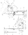
図3または図4に示すように、保持手段26は、袋詰サンドイッチ10における左右の両側面を挟持して左右方向への移動を規制する一対の挟持部材28,28と、両挟持部材28,28の間に受け入れてターンテーブル24に載置した袋詰サンドイッチ10の前側傾斜面10aに当接して、袋詰サンドイッチ10の前側(ターンテーブル24の回転中心方向)の位置規制をする規制部材30とを備えている。この規制部材30によって、袋詰サンドイッチ10におけるサンドイッチ16の後側端面16aが、ターンテーブル24の半径方向前後の所定位置で位置付けられる。
As shown in FIG. 3 or FIG. 4, the holding means 26 includes a pair of sandwiching
前記一対の挟持部材28,28は、ターンテーブル24の周方向へ平行に離間して立設され、保持手段26に受け入れた袋詰サンドイッチ10の左右各側面を各挟持部材28の挟持面で挟持可能に配置されている。ターンテーブル24の上側に延出した各挟持部材28の挟持面は、サンドイッチ16の側面の大部分の範囲を挟み得る大きさの三角平面形状に形成される。すなわち、傾斜面がターンテーブル24の回転中心方向に臨むサンドイッチ16を保持手段26で保持するので、各挟持部材28は回転中心方向から半径方向外側に向かうにつれて上方傾斜する略三角平面形状に形成される(図2(b)参照)。また、各挟持部材28は、ターンテーブル24に開設した開口24aを介して下側に突出すると共に、その下端部は移動体32に夫々配設される。各移動体32は、一対のガイドロッド34,34に摺動自在に夫々配設され、該ガイドロッド34,34に沿って相互に近接・離間移動し得るようになっている。そして、移動体32,32とガイドロッド34,34からなるスライド手段によって、一対の挟持部材28,28がターンテーブル24に載置した袋詰サンドイッチ10の側面を挟持する挟持位置と、互いに離間して挟持状態を解除する開放位置との間を移動するよう構成されている。
The pair of sandwiching
図3および図4に示すように、前記一対の挟持部材28,28の移動範囲より外側でターンテーブル24の上面に一対の支持体36,36が立設され、両支持体36,36の間に、2個の規制部材30,30が前後方向と上下方向とに位置をずらして水平に架設される。そして、規制部材30は、挟持部材28における前側傾斜辺の前方を横切るよう配設されている。各規制部材30は、少なくとも袋詰サンドイッチ10の前側傾斜面10aに当接する部位が円弧状に形成された棒状材であることが好ましく、実施例では丸棒が用いられている。そして、下側に位置する規制部材30が、上側に位置する規制部材30より前方に配置され、各規制部材30が搬入コンベアC1から保持手段26に受け入れた袋詰サンドイッチ10の前方への移動を規制し得るようになっている(図5参照)。それにより、保持手段26は、挟持部材28,28の間に受け入れた袋詰サンドイッチ10におけるサンドイッチ16の後側端面16aが半径方向前後の所定位置に位置揃えされて、フィルム延出部14がターンテーブル24の半径方向外側へ向けて突出した状態となる。
As shown in FIG. 3 and FIG. 4, a pair of
各規制部材30には、袋詰サンドイッチ10の前側傾斜面10aの形成状態に応じて、袋詰サンドイッチ10の前側傾斜面10aに当接する高さ位置と該前側傾斜面10aに当接する前後位置とを調節可能に構成した調節手段38が設けられる。調節手段38は、規制部材30,30の夫々を、独立して設定高さと前後位置との夫々を調節可能になっている。調節手段38は、保持手段26に設けた一対の支持体36の夫々に回動可能に支持された調節回転体40,40からなり、両調節回転体40,40に亘り、該調節回転体40,40の回動中心から所定間隔離間した偏心位置に規制部材30が架設されている。そして、両調節回転体40,40の周囲を摘んで同一方向へ回動するだけのワンアクションの操作で、高さ位置と前後位置とが併せて変位するように調節される。
Each regulating
前記調節手段38は、調節回転体40における支持体36に臨む面に、周方向に所定角度間隔で形成された複数の凹部42aと、調節回転体40に対して所定の付勢力を付与して、凹部42aに弾力的に係脱可能なボールプランジャなどの係止体42bとからなる係止手段42を有している。調節回転体40には、その回動方向へ所定角度毎に凹部42aが複数箇所設けられ、係止手段42により規制部材30を上下60°ずつの振り幅となるように調節回転体40を所定角度単位で位置決めし得るようになっている。係止体42bは、先端のボールがバネに付勢されて凹部42aに嵌り込んで、調節回転体40の回動方向へ回動を所定角度毎に係止する。調節回転体40の回動軸40aには、該調節回転体40と一体回動する指針46が支持体36の左右両側面に配設され、支持体36の側面に表示された指標部48に対して指針46が指し示す目盛値により、規制部材30の高さ位置および前後位置を目盛値に合わせて設定し得る。
The adjustment means 38 applies a predetermined urging force to the
前記一対の移動体32,32は、ターンテーブル24における受入位置PNおよび送出位置PSでは、左右方向へ互いに離間する側へ変位されて、これに対応して挟持部材28,28が互いに離間する側へ変位して袋詰サンドイッチ10の受け入れまたは送り出しを許容するよう構成される。また、一対の移動体32,32は、ターンテーブル24の受入位置PNから送出位置PSへの搬送過程では、付勢手段50により互いに近接する側に変位されて、これに対応して挟持部材28,28が互いに近接する側へ変位して袋詰サンドイッチ10の左右両側面を挟持して位置決めすると共に、ターンテーブル24の回転に際して袋詰サンドイッチ10の半径方向外側への移動を規制するようになっている。
The pair of moving
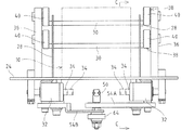
前記ターンテーブル24の下方には、該ターンテーブル24の回転軸25と同軸的に作動カム52が配設され、該作動カム52は回転軸24aに第1軸受を介して回転自在で、かつ前記装置基部21に対して第2軸受を介して回転自在に支持され、ターンテーブル24とは独立して回動し得るよう構成される。各保持手段26の移動体32,32に対応してターンテーブル24の裏面に、連動リンク手段としての第1および第2のリンクレバー54A,54Bが、L字形アームの屈曲部を支点としてターンテーブル24の裏面に揺動可能に配設され、一方のアームの延出端に形成された係合溝55に、対応する移動体32の下方に自由回転可能に設けられたローラ58が夫々係合すると共に、両リンクレバー54A,54Bの他方のアームの延出端が互いに回動可能に連結されている(図6(a)参照)。なお、上方に位置する第2のリンクレバー54Bにおける第1のリンクレバー54Aとの連結部のアーム先端には、連結溝56が切欠き形成され、この連結溝56に第1のリンクレバー54Aに配設された連結ローラ60が係合することで、夫々のリンクレバー54A,54Bが連結されている(図6(b)参照)。
Below the
前記第2のリンクレバー54Bにおける第1のリンクレバー54Aとの連結部には、引っ張りばね等からなる付勢手段50の一方が接続され、この付勢手段50の他方がターンテーブル24の裏面に設けた係止部62に接続されて、ターンテーブル24の中心へ向けて常に付勢されている。また、第1のリンクレバー54Aには、連結ローラ60と同心的に作動ローラ64が自由回転可能に配設され、その周面が作動カム52における大径部の周面を転動するよう構成されている。これにより両リンクレバー54A,54Bは同期的に揺動して、挟持部材28,28が左右方向へ一体的に同一の距離だけ近接離間移動し得るよう設定され、挟持部材28,28で挟持した袋詰サンドイッチ10が、保持手段26における左右方向の略中心に、袋詰サンドイッチ10の左右幅の略中心を整合させて挟持中心を常に一定にするようセンタリングされる。
One of biasing means 50 made of a tension spring or the like is connected to the connecting portion of the
前記作動カム52は、その大径部が常には前記送出位置PSから受入位置PNに到る位置までの間に位置決めされると共に、受入位置PNにおいて袋詰サンドイッチ10が搬入コンベアC1からターンテーブル24に移載されると、ターンテーブル24の回転開始前に該ターンテーブル24の回転方向と逆向き(実施例では反時計廻り)に図示しない駆動手段により所定角度だけ回動して受入位置PNに小径部を位置させた後、ターンテーブル24が回転すると共に元の位置(ターンテーブル24の回転方向)に回動するよう設定される。このように、作動ローラ64が作動カム52の大径部から小径部に移行することで、袋詰サンドイッチ10が受入位置PNから送出位置PSまで搬送される間において、一対の挟持部材28,28は付勢手段50の付勢作用下に袋詰サンドイッチ10の側面を弾力的に挟持する。また、各保持手段26が送出位置PSから受入位置PNに到るまでは、対応する作動ローラ64が作動カム52の大径部を転動して挟持部材28,28が互いに離間した開放状態になるよう構成される。なお、挟持部材28,28で袋詰サンドイッチ10が挟持されないときには、作動ローラ64が作動カム52の小径部を転動して、一対の挟持部材28,28が互いに近接した所定位置に維持されるよう構成される。
The operating
〔実施例の作用〕
次に、実施例に係るサンドイッチ包装機20の袋詰サンドイッチ保持装置の作用について説明する。規制部材30は、調節手段38の調節回転体40を回動操作することで、ターンテーブル24における保持手段26の載置面からの高さ位置を上下調整できると共に、袋詰サンドイッチ10が保持手段26に受け入れられたときの前側の規制位置を前後調整できる。そして、前後に離間配置された2個の両規制部材30,30の夫々が、独立して上下と前後とに位置調節可能である。また、指針46が指し示す指標部48の目盛値に合わせて、規制部材30の高さと前後位置とを調節することで、サンドイッチ16の傾斜角度など異なる形状の品種切り換え時に位置決め設定を再現することができる。袋詰サンドイッチ10の前側傾斜面10aの傾斜角度に合わせて、2個の規制部材30,30の高さと前後位置とを調節することで、傾斜角度など複数品種のサンドイッチ16に対応した外形の変化に応じて、保持手段26に保持された袋詰サンドイッチ10の後側端面16aが揃うように位置決めすることができ、袋詰サンドイッチ10におけるフィルム延出部14を折り畳んで封止する際の基準位置が定位置で位置付けられる。フィルム延出部14のサンドイッチ16の後側端面16aへの折り畳みに際して、フィルムのだぶつきを防いで後側端面16aに沿って折り重ねることができ、その折り畳み状態で袋口12を封止することができ、異なるサンドイッチ16間の包装であっても包装の見栄えを低下させることなく、良好な包装がなされたサンドイッチ包装品13を得ることができる。
(Effects of Example)
Next, the operation of the packaged sandwich holding device of the
前記保持手段26は、2個の規制部材30,30の夫々について高さ位置と前後位置と調節するだけの簡素な調節形態にも関わらず、サンドイッチ16のサイズや形状の違いによる袋詰サンドイッチ10の前側傾斜面10aの傾斜角度や前後位置の変化に対応できる。また、調節回転体40の偏心位置に規制部材30を配設した構成の調節手段38としたので、調節回転体40を回動するだけのワンアクションの操作で、規制部材30の高さ位置と前後位置とを一緒に調節できるから、調節作業が非常に楽で短時間で行うことができる。
The holding means 26 is not limited to the height adjustment and the front-rear position of each of the two regulating
(変更例)
本発明は実施例の構成に限定されるものではなく、例えば、以下のようにも変更実施可能である。また、以下の変更例に限らず、実施例に記載した構成については、本発明の主旨の範囲内において種々の実施形態を採用し得る。
(1)調節手段38は、調節回転体40の回動により規制部材30を位置調節する構成に限られず、支持体36に配設されたガイドなどに沿って斜め前後方向に移動して規制部材30を位置調節する構成やその他の構成を採用し得る。
(2)調節手段38による調節可能角度範囲は、実施例に限られず、また係止手段42による回動規制ピッチも実施例に限られず、適宜に設定することができる。また、調節手段38は、無段階調節可能な構成としてもよい。調節回転体を一端が回動可能に支持されると共に他端に規制部材30を配設したアームで構成し、該アームを回動中心に対して規制部材30の配設位置が近接または離間するように伸縮可能とするなどにより、調節回転体の回動中心からの規制部材30の離間間隔を変更可能に構成してもよい。
(3)規制部材30は、1つであってもよい。
(4)保持手段26は、ターンテーブル24に配設される構成に限られず、搬送手段22によって保持手段26が上流から下流側に直線的に搬送される際に、保持手段26で袋詰サンドイッチ10を支持して、袋口12側が所定位置で位置付けられて折り畳み封止される形態の各種のサンドイッチ包装機に、本発明を適用可能である。
(Example of change)
The present invention is not limited to the configuration of the embodiment, and can be modified as follows, for example. Further, not limited to the following modification examples, various embodiments may be adopted for the configurations described in the examples within the scope of the gist of the present invention.
(1) The adjusting means 38 is not limited to the configuration in which the position of the regulating
(2) The adjustable angle range by the adjusting means 38 is not limited to the embodiment, and the rotation restricting pitch by the locking means 42 is not limited to the embodiment, and can be set as appropriate. The adjusting means 38 may be configured to be continuously adjustable. The adjusting rotator is composed of an arm having one end rotatably supported and a restricting
(3) One
(4) The holding means 26 is not limited to the configuration arranged on the
10 袋詰サンドイッチ,10a 前側傾斜面,11 袋,12 袋口,
16 サンドイッチ(三角サンドイッチ),16a 後側端面,22 搬送手段,
26 保持手段,30 規制部材,36 支持体,38 調節手段,40 調節回転体
10 bagging sandwiches, 10a front inclined surface, 11 bags, 12 bag mouths,
16 sandwich (triangular sandwich), 16a rear end face, 22 transport means,
26 holding means, 30 regulating member, 36 support, 38 adjusting means, 40 adjusting rotating body
Claims (3)
前記搬送手段(22)に、その搬送方向に所定間隔毎に設けられ、該搬送手段(22)に受け入れた前記袋詰サンドイッチ(10)を外側方に向けて個々に保持する保持手段(26)を備え、
前記保持手段(26)は、前記袋詰サンドイッチ(10)の前側傾斜面(10a)に当接して、前記搬送手段(22)の外側方を向くサンドイッチ(16)の後側端面(16a)の前後位置を位置決めする規制部材(30)を備え、該規制部材(30)には、袋詰サンドイッチ(10)の前側傾斜面(10a)に当接する高さ位置と該前側傾斜面(10a)に当接する前後位置とを調節する調節手段(38)を配設し、
前記調節手段(38)は、ワンアクションで前記規制部材(30)の上下と前後とに移動調節し得る構成とした
ことを特徴とするサンドイッチ包装機の袋詰サンドイッチ保持装置。 In the process of supporting and transporting the bag sandwich (10) containing the triangular sandwich (16) in the bag (11) with one end opened by the transport means (22), the bag is directed to the outside of the transport means (22). In the sandwich sandwich holding device of the sandwich packaging machine that folds and seals the bag mouth (12),
Wherein the transport means (22), that provided in the transfer direction for each Jo Tokoro intervals, holding means (26 to hold the conveying means the bagging sandwich received in (22) (10) individually towards the outer side )
The holding means (26) contacts the front inclined surface (10a) of the bagging sandwich (10) and faces the outer side of the conveying means (22), and the rear end surface (16a) of the sandwich (16) faces the outside. A regulating member (30) for positioning the front-rear position is provided, and the regulating member (30) has a height position contacting the front inclined surface (10a) of the bagging sandwich (10) and the front inclined surface (10a). An adjusting means (38) for adjusting the abutting front and back position is provided ,
The packing sandwich holding device for a sandwich packaging machine, wherein the adjusting means (38) is configured to be movable and adjusted up and down and front and rear of the regulating member (30) with one action .
前記搬送手段(22)に、その搬送方向に所定間隔毎に設けられ、該搬送手段(22)に受け入れた前記袋詰サンドイッチ(10)を外側方に向けて個々に保持する保持手段(26)を備え、
前記保持手段(26)は、前記袋詰サンドイッチ(10)の前側傾斜面(10a)に当接して、前記搬送手段(22)の外側方を向くサンドイッチ(16)の後側端面(16a)の前後位置を位置決めする規制部材(30)を備え、該規制部材(30)には、袋詰サンドイッチ(10)の前側傾斜面(10a)に当接する高さ位置と該前側傾斜面(10a)に当接する前後位置とを調節する調節手段(38)を配設し、
前記調節手段(38)は、前記保持手段(26)に設けた一対の支持体(36,36)の夫々に回動可能に支持された調節回転体(40,40)を備え、両調節回転体(40,40)に亘り、その回動中心から所定間隔離間した位置に前記規制部材(30)を架設した
ことを特徴とするサンドイッチ包装機の袋詰サンドイッチ保持装置。 In the process of supporting and transporting the bag sandwich (10) containing the triangular sandwich (16) in the bag (11) with one end opened by the transport means (22), the bag is directed to the outside of the transport means (22). In the sandwich sandwich holding device of the sandwich packaging machine that folds and seals the bag mouth (12),
Holding means (26) provided in the conveying means (22) at predetermined intervals in the conveying direction and individually holding the bag sandwich (10) received by the conveying means (22) outward. With
The holding means (26) contacts the front inclined surface (10a) of the bagging sandwich (10) and faces the outer side of the conveying means (22), and the rear end surface (16a) of the sandwich (16) faces the outside. A regulating member (30) for positioning the front-rear position is provided, and the regulating member (30) has a height position contacting the front inclined surface (10a) of the bagging sandwich (10) and the front inclined surface (10a). An adjusting means (38) for adjusting the abutting front and back position is provided,
The adjustment means (38) includes an adjustment rotator (40, 40) rotatably supported by each of a pair of supports (36, 36) provided in the holding means (26), and both adjustment rotations body (40, 40) over said regulating member (30) the packaged sandwich holding device characteristics and to salicylate sandwich packaging machine that bridged from the rotation center to the predetermined distance spaced locations.
Priority Applications (1)
| Application Number | Priority Date | Filing Date | Title |
|---|---|---|---|
| JP2014031638A JP6105505B2 (en) | 2014-02-21 | 2014-02-21 | Sandwich packing machine for sandwich packing machine |
Applications Claiming Priority (1)
| Application Number | Priority Date | Filing Date | Title |
|---|---|---|---|
| JP2014031638A JP6105505B2 (en) | 2014-02-21 | 2014-02-21 | Sandwich packing machine for sandwich packing machine |
Publications (3)
| Publication Number | Publication Date |
|---|---|
| JP2015155326A JP2015155326A (en) | 2015-08-27 |
| JP2015155326A5 JP2015155326A5 (en) | 2015-12-10 |
| JP6105505B2 true JP6105505B2 (en) | 2017-03-29 |
Family
ID=54774926
Family Applications (1)
| Application Number | Title | Priority Date | Filing Date |
|---|---|---|---|
| JP2014031638A Active JP6105505B2 (en) | 2014-02-21 | 2014-02-21 | Sandwich packing machine for sandwich packing machine |
Country Status (1)
| Country | Link |
|---|---|
| JP (1) | JP6105505B2 (en) |
Family Cites Families (7)
| Publication number | Priority date | Publication date | Assignee | Title |
|---|---|---|---|---|
| JPH0379158U (en) * | 1989-11-30 | 1991-08-12 | ||
| JPH0769317A (en) * | 1993-09-03 | 1995-03-14 | Sakae Matsuyama | Sealing tape adhering device for sandwich packing bag |
| JPH10310109A (en) * | 1997-05-07 | 1998-11-24 | Susumu Yamazaki | Packaging device and carrying bucket |
| JPH11301615A (en) * | 1998-04-20 | 1999-11-02 | Nippo Kk | Bag-filling machine for sandwich or the like |
| JP4392536B2 (en) * | 2004-11-15 | 2010-01-06 | 株式会社フジキカイ | Sandwich packaging method and packaging apparatus |
| JP4355946B2 (en) * | 2004-11-19 | 2009-11-04 | 株式会社フジキカイ | Bag mouth folding device for sandwich packaging machine |
| JP4355951B2 (en) * | 2005-02-07 | 2009-11-04 | 株式会社フジキカイ | Sandwich packaging machine conveyor |
-
2014
- 2014-02-21 JP JP2014031638A patent/JP6105505B2/en active Active
Also Published As
| Publication number | Publication date |
|---|---|
| JP2015155326A (en) | 2015-08-27 |
Similar Documents
| Publication | Publication Date | Title |
|---|---|---|
| JP6746467B2 (en) | Gripper device of bag packing machine | |
| JP6140086B2 (en) | Bag transfer device | |
| JP5419798B2 (en) | Intermittent rotary table type bag filling and packaging machine | |
| JP6140125B2 (en) | Bag transfer device | |
| JP6235497B2 (en) | Packaging equipment | |
| JP6444807B2 (en) | Detection method for detecting a holding state by a gripper device, a detection device, and a bagging and packaging machine | |
| JP4355951B2 (en) | Sandwich packaging machine conveyor | |
| JP6847539B2 (en) | Supply method and equipment for bags filled with solids | |
| JP6134472B2 (en) | Cutter device for packaging bag | |
| JP6105505B2 (en) | Sandwich packing machine for sandwich packing machine | |
| JP6731363B2 (en) | Position adjustment mechanism | |
| AU2013267060B2 (en) | A packaging machine former | |
| JP6154796B2 (en) | Sealing device for horizontal bag making and filling machine | |
| JP2004284603A (en) | Article transfer device in bread bagging machine | |
| JP6072113B2 (en) | Twist packaging equipment | |
| JP2019085151A (en) | Pre-transport device of integrated packing machine | |
| JP2009280259A (en) | Bag making-packaging machine | |
| JP2011084326A (en) | Packaging film synchronizing apparatus for multi-train roll type automatic packaging machine | |
| JP6765785B2 (en) | Bag making and packaging machine | |
| JP6542160B2 (en) | Position adjustment unit | |
| JP6542167B2 (en) | Horizontal pillow packing machine | |
| JPH06286731A (en) | Simplified 3-way sealing machine | |
| JP5647088B2 (en) | Film folding device for packaging machine | |
| JP4405840B2 (en) | End seal device | |
| JP2019214397A (en) | Folding device and pillow packaging machine |
Legal Events
| Date | Code | Title | Description |
|---|---|---|---|
| A521 | Request for written amendment filed |
Free format text: JAPANESE INTERMEDIATE CODE: A523 Effective date: 20151021 |
|
| A621 | Written request for application examination |
Free format text: JAPANESE INTERMEDIATE CODE: A621 Effective date: 20151021 |
|
| A977 | Report on retrieval |
Free format text: JAPANESE INTERMEDIATE CODE: A971007 Effective date: 20160822 |
|
| A131 | Notification of reasons for refusal |
Free format text: JAPANESE INTERMEDIATE CODE: A131 Effective date: 20160830 |
|
| A521 | Request for written amendment filed |
Free format text: JAPANESE INTERMEDIATE CODE: A523 Effective date: 20160928 |
|
| TRDD | Decision of grant or rejection written | ||
| A01 | Written decision to grant a patent or to grant a registration (utility model) |
Free format text: JAPANESE INTERMEDIATE CODE: A01 Effective date: 20170228 |
|
| A61 | First payment of annual fees (during grant procedure) |
Free format text: JAPANESE INTERMEDIATE CODE: A61 Effective date: 20170302 |
|
| R150 | Certificate of patent or registration of utility model |
Ref document number: 6105505 Country of ref document: JP Free format text: JAPANESE INTERMEDIATE CODE: R150 |
|
| R250 | Receipt of annual fees |
Free format text: JAPANESE INTERMEDIATE CODE: R250 |
|
| R250 | Receipt of annual fees |
Free format text: JAPANESE INTERMEDIATE CODE: R250 |
|
| R250 | Receipt of annual fees |
Free format text: JAPANESE INTERMEDIATE CODE: R250 |