JP6103341B2 - Lubricant supply device, image forming apparatus, and process cartridge - Google Patents

Lubricant supply device, image forming apparatus, and process cartridge Download PDF

Info

Publication number
JP6103341B2
JP6103341B2 JP2012169993A JP2012169993A JP6103341B2 JP 6103341 B2 JP6103341 B2 JP 6103341B2 JP 2012169993 A JP2012169993 A JP 2012169993A JP 2012169993 A JP2012169993 A JP 2012169993A JP 6103341 B2 JP6103341 B2 JP 6103341B2
Authority
JP
Japan
Prior art keywords
electrode member
lubricant
supply device
lubricant supply
electrode
Prior art date
Legal status (The legal status is an assumption and is not a legal conclusion. Google has not performed a legal analysis and makes no representation as to the accuracy of the status listed.)
Active
Application number
JP2012169993A
Other languages
Japanese (ja)
Other versions
JP2014029414A5 (en
JP2014029414A (en
Inventor
大輔 富田
大輔 富田
新谷 剛史
剛史 新谷
経生 工藤
経生 工藤
賢二 本城
賢二 本城
羽鳥 聡
聡 羽鳥
熊谷 直洋
直洋 熊谷
彰 藤森
彰 藤森
吉野 薫
薫 吉野
雄太 畔柳
雄太 畔柳
秀康 関
秀康 関
良太 後藤
良太 後藤
Current Assignee (The listed assignees may be inaccurate. Google has not performed a legal analysis and makes no representation or warranty as to the accuracy of the list.)
Ricoh Co Ltd
Original Assignee
Ricoh Co Ltd
Priority date (The priority date is an assumption and is not a legal conclusion. Google has not performed a legal analysis and makes no representation as to the accuracy of the date listed.)
Filing date
Publication date
Application filed by Ricoh Co Ltd filed Critical Ricoh Co Ltd
Priority to JP2012169993A priority Critical patent/JP6103341B2/en
Priority to US13/936,669 priority patent/US9052669B2/en
Priority to CN201310307726.5A priority patent/CN103576521B/en
Publication of JP2014029414A publication Critical patent/JP2014029414A/en
Publication of JP2014029414A5 publication Critical patent/JP2014029414A5/ja
Application granted granted Critical
Publication of JP6103341B2 publication Critical patent/JP6103341B2/en
Active legal-status Critical Current
Anticipated expiration legal-status Critical

Links

Images

Classifications

    • GPHYSICS
    • G03PHOTOGRAPHY; CINEMATOGRAPHY; ANALOGOUS TECHNIQUES USING WAVES OTHER THAN OPTICAL WAVES; ELECTROGRAPHY; HOLOGRAPHY
    • G03GELECTROGRAPHY; ELECTROPHOTOGRAPHY; MAGNETOGRAPHY
    • G03G15/00Apparatus for electrographic processes using a charge pattern
    • G03G15/55Self-diagnostics; Malfunction or lifetime display
    • G03G15/553Monitoring or warning means for exhaustion or lifetime end of consumables, e.g. indication of insufficient copy sheet quantity for a job
    • GPHYSICS
    • G03PHOTOGRAPHY; CINEMATOGRAPHY; ANALOGOUS TECHNIQUES USING WAVES OTHER THAN OPTICAL WAVES; ELECTROGRAPHY; HOLOGRAPHY
    • G03GELECTROGRAPHY; ELECTROPHOTOGRAPHY; MAGNETOGRAPHY
    • G03G21/00Arrangements not provided for by groups G03G13/00 - G03G19/00, e.g. cleaning, elimination of residual charge
    • G03G21/0094Arrangements not provided for by groups G03G13/00 - G03G19/00, e.g. cleaning, elimination of residual charge fatigue treatment of the photoconductor

Description

本発明は、潤滑剤供給装置、画像形成装置およびプロセスカートリッジに関するものである。   The present invention relates to a lubricant supply device, an image forming apparatus, and a process cartridge.

プリンタ、ファクシミリ、複写機などの画像形成装置において、感光体や中間転写ベルトなどの像担持体の保護や低摩擦化のため像担持体の表面に潤滑剤を供給する潤滑剤供給装置を備えたものが知られている。   Image forming apparatuses such as printers, facsimiles, and copiers are provided with a lubricant supply device that supplies lubricant to the surface of the image carrier in order to protect the image carrier such as a photoconductor and an intermediate transfer belt and to reduce friction. Things are known.

また、潤滑剤が枯渇した状態で画像形成動作が行われると、潤滑剤の保護作用が働かないため、像担持体が磨耗して劣化してしまう。特許文献1には、潤滑剤のニアエンドを検知する潤滑剤供給装置が記載されている。   Further, when the image forming operation is performed in a state where the lubricant is depleted, the protective action of the lubricant does not work, so that the image carrier is worn and deteriorated. Patent Document 1 describes a lubricant supply device that detects the near end of a lubricant.

図26は、特許文献1に記載の潤滑剤供給装置の潤滑剤ニアエンド検知部を示す概略斜視図である。
図26に示すように、固形潤滑剤140を保持する潤滑剤保持部材143を導電性部材で構成し、潤滑剤の残量が少なくなった時点で潤滑剤保持部材143の一端に当接する第1電極部材181と、他端に当接する第2電極部材182とを有している。第1電極部材181と第2電極部材182とには、検知回路183が接続されており、検知回路183は、電極部材間に電圧を印加して、電流が流れたか否かを検知する。また、潤滑剤保持部材143は、バネ142により不図示の供給部材側に付勢されている。
FIG. 26 is a schematic perspective view showing a lubricant near-end detection unit of the lubricant supply device described in Patent Document 1.
As shown in FIG. 26, the lubricant holding member 143 that holds the solid lubricant 140 is formed of a conductive member, and contacts the first end of the lubricant holding member 143 when the remaining amount of the lubricant decreases. It has an electrode member 181 and a second electrode member 182 in contact with the other end. A detection circuit 183 is connected to the first electrode member 181 and the second electrode member 182, and the detection circuit 183 detects whether or not a current flows by applying a voltage between the electrode members. Further, the lubricant holding member 143 is urged toward a supply member (not shown) by a spring 142.

使用初期は、各電極部材に対し潤滑剤保持部材143が離間しており、電極部材間には電流が流れない。固形潤滑剤が不図示の供給部材による摺擦で徐々に削られながら、バネ142の付勢力により潤滑剤保持部材143が供給部材側へと移動していく。そして、固形潤滑剤140がニアエンドとなると、導電性の潤滑剤保持部材143が、第1電極部材181、第2電極部材182と当接する。その結果、電極部材間に電流が流れ、検知回路183で潤滑剤のニアエンドが検知される。   In the initial stage of use, the lubricant holding member 143 is separated from each electrode member, and no current flows between the electrode members. The lubricant holding member 143 moves to the supply member side by the urging force of the spring 142 while the solid lubricant is gradually scraped by rubbing with a supply member (not shown). When the solid lubricant 140 becomes near-end, the conductive lubricant holding member 143 comes into contact with the first electrode member 181 and the second electrode member 182. As a result, a current flows between the electrode members, and the detection circuit 183 detects the near end of the lubricant.

しかしながら、特許文献1に記載の潤滑剤供給装置においては、潤滑剤の残量が少なくなってはじめて潤滑剤保持部材143が各電極部材181,182と当接し導通する構成である。使用初期から潤滑剤の残量が少なくなるまでの間は、潤滑剤保持部材143と電極部材181,182とは離間している。よって、潤滑剤の残量が少なくなるまでの間に、電極部材181,182の潤滑剤保持部材143との当接部(以下、電極部材側当接部という)や潤滑剤保持部材143の電極部材181,182との当接部(以下、潤滑剤保持部材側当接部という)に潤滑剤が付着するおそれがある。これらの当接部に潤滑剤が付着すると、潤滑剤保持部材143が電極部材181,182と当接しても導通状態とならず、潤滑剤のニアエンドを検知することができないおそれがあった。   However, the lubricant supply device described in Patent Document 1 has a configuration in which the lubricant holding member 143 contacts the electrode members 181 and 182 and becomes conductive only after the remaining amount of the lubricant is reduced. The lubricant holding member 143 and the electrode members 181 and 182 are separated from the initial use until the remaining amount of the lubricant is reduced. Therefore, until the remaining amount of the lubricant decreases, the contact portions of the electrode members 181 and 182 with the lubricant holding member 143 (hereinafter referred to as electrode member side contact portions) and the electrodes of the lubricant holding member 143 There is a possibility that the lubricant adheres to the contact portions with the members 181 and 182 (hereinafter referred to as the lubricant holding member side contact portion). If the lubricant adheres to these contact portions, even if the lubricant holding member 143 comes into contact with the electrode members 181 and 182, the conductive state is not established, and the near end of the lubricant may not be detected.

本発明は以上の課題に鑑みなされたものであり、その目的は、固形潤滑剤の残量が所定量以下となったことを確実に検知することができる潤滑剤供給装置、画像形成装置およびプロセスカートリッジを提供することである。   The present invention has been made in view of the above problems, and an object of the present invention is to provide a lubricant supply device, an image forming apparatus, and a process that can reliably detect that the remaining amount of the solid lubricant has become a predetermined amount or less. It is to provide a cartridge.

上記目的を達成するために、請求項1の発明は、潤滑剤と、上記潤滑剤を潤滑剤供給対象に供給する供給部材と、第1電極部材と第2電極部材との導通状態を検知する導通検知手段と、を備え、上記第1電極部材と上記第2電極部材との導通状態により、上記潤滑剤の残量が所定量以下であることが判定される潤滑剤供給装置において、上記第2電極部材は、上記潤滑剤の消費に伴い移動する移動部材に直接または間接的に押されると、一端を支点にして撓み変形するものであって、上記第2電極部材に、上記第1電極部材側に突出し、上記第1電極部材に当接する突出部を設けたことを特徴とするものである。   In order to achieve the above object, the invention of claim 1 detects a conduction state between a lubricant, a supply member that supplies the lubricant to a lubricant supply target, and a first electrode member and a second electrode member. A lubricant supply device comprising: a continuity detecting means; wherein the remaining amount of the lubricant is determined to be equal to or less than a predetermined amount based on a continuity between the first electrode member and the second electrode member. When the two-electrode member is directly or indirectly pushed by the moving member that moves as the lubricant is consumed, the two-electrode member bends and deforms with one end as a fulcrum, and the second electrode member has the first electrode A protruding portion that protrudes toward the member and contacts the first electrode member is provided.

本発明者らは、電極部材への潤滑剤の付着による誤検知を鋭意研究した結果、次のような知見を得た。すなわち、先の図26に示した特許文献1に記載の潤滑剤供給装置は、潤滑剤保持部材143の面と各電極部材181,182の面とを当接させる構成である。このように、面接触する構成であるため、潤滑剤保持部材が各電極部材に当接するとき、潤滑剤保持部材や各電極部材に付着した潤滑剤などの付着物を押し退けるほどの当接圧が働かない。また、潤滑剤保持部材がある程度広い範囲で一斉に電極部材に当接するため、付着物の逃げ場がない。その結果、潤滑剤保持部材の当接部と、各電極部材の当接部との間に付着物が挟まり、潤滑剤保持部材143と電極部材181,182との間に接触不良が生じ、潤滑剤のニアエンドを検知することができないという知見である。   As a result of earnest research on false detection due to adhesion of lubricant to the electrode member, the present inventors have obtained the following knowledge. That is, the lubricant supply device described in Patent Document 1 shown in FIG. 26 has a configuration in which the surface of the lubricant holding member 143 and the surfaces of the electrode members 181 and 182 are brought into contact with each other. As described above, since the structure is in surface contact, when the lubricant holding member comes into contact with each electrode member, the contact pressure is high enough to push away the lubricant holding member and the adhering material such as the lubricant attached to each electrode member. Does not work. In addition, since the lubricant holding member is in contact with the electrode member all at once in a certain wide range, there is no place for the deposit to escape. As a result, an adhering matter is caught between the contact portion of the lubricant holding member and the contact portion of each electrode member, resulting in poor contact between the lubricant holding member 143 and the electrode members 181 and 182. This is a finding that the near end of the agent cannot be detected.

そこで、本発明においては、上記知見に基づき、第1電極部材または第2電極部材に、他方の電極部材側に突出する突出部設け、突出部を他方の電極部材と当接させた。これにより、面同士を当接させる場合に比べて、当接圧を高めることができ、かつ、当接する範囲を狭めることができる。これにより、第2電極部材が第1電極部材に当接する際に電極部材に付着した付着物を押し退けることができ、電極部材間に付着物が挟まるのを抑制することができる。よって、滑剤の量が所定以下となると、良好に導通し、良好に潤滑剤の残量を検知することができる。 Therefore, in the present invention, based on the above findings, the first electrode member or the second electrode member, disposed protrusion protruding to the other electrode member, and the protruding portion is in contact with the other electrode member. Thereby, compared with the case where surfaces contact | abut, contact pressure can be raised and the range to contact | abut can be narrowed. Thereby, when the 2nd electrode member contact | abuts to the 1st electrode member, the deposit | attachment adhering to the electrode member can be pushed away, and it can suppress that an deposit | attachment pinches between electrode members. Therefore, the amount of or lubricants is given below, satisfactorily conductive, it is possible to detect the remaining amount of the good lubricant.

本発明によれば、電極部材に付着した付着物による電極部材間の接触不良を抑制することができ、潤滑剤の残量が所定量以下となったことを確実に検知することができる。 According to the present invention, it is possible to suppress the contact failure between the electrode members by deposits adhered to the electrode member can be remaining amount of Jun lubricant detects reliably be equal to or less than a predetermined amount.

実施形態に係るプリンタを示す概略構成図である。1 is a schematic configuration diagram illustrating a printer according to an embodiment. 4つの作像ユニットのうちの1つを示す拡大図である。It is an enlarged view which shows one of four image formation units. クリーニング装置と潤滑剤塗布装置とを備えたユニットを示す概略構成図。The schematic block diagram which shows the unit provided with the cleaning apparatus and the lubricant coating device. 潤滑剤供給装置の長手方向一端側を示す概略構成図。The schematic block diagram which shows the longitudinal direction one end side of a lubricant supply apparatus. 図4のA−A断面図。AA sectional drawing of FIG. 図4のB−B断面図。BB sectional drawing of FIG. 第1電極部材42aと第2電極部材42bとを示す斜視図。The perspective view which shows the 1st electrode member 42a and the 2nd electrode member 42b. 潤滑剤供給装置3の長手方向一端側を感光体側から見た図。The figure which looked at the longitudinal direction one end side of the lubricant supply apparatus 3 from the photoreceptor side. 従来の残量検知部の一例を示す図。The figure which shows an example of the conventional residual amount detection part. 図9の従来の残量検知部におけるニアエンド検知状態を示す図。The figure which shows the near end detection state in the conventional residual amount detection part of FIG. 突出部の第1変形例を示す図。The figure which shows the 1st modification of a protrusion part. 突出部の第2変形例を示す図。The figure which shows the 2nd modification of a protrusion part. 突出部の第3変形例を示す図。The figure which shows the 3rd modification of a protrusion part. 突出部の第4変形例を示す図。The figure which shows the 4th modification of a protrusion part. 突出部の第5変形例を示す図。The figure which shows the 5th modification of a protrusion part. 第1電極部材と第2電極部材との間に清掃ブラシを配置した実施例を示す図。The figure which shows the Example which has arrange | positioned the cleaning brush between the 1st electrode member and the 2nd electrode member. 遮蔽部材を設けた実施例の分解斜視図。The disassembled perspective view of the Example which provided the shielding member. 遮蔽部材を設けた実施例を示す図。The figure which shows the Example which provided the shielding member. 潤滑剤残量検知の制御フロー図。FIG. 5 is a control flow diagram for detecting the remaining amount of lubricant. 塗布ローラの走行距離および残量検知部の両方でニアエンドを行う場合の制御フロー図。The control flow figure in the case of performing a near end in both the travel distance and remaining amount detection part of an application | coating roller. 固形潤滑剤量の推移とニアエンド検知のタイミングとを示す図。The figure which shows transition of the amount of solid lubricants, and the timing of near-end detection. 第1電極部材と第2電極部材とを水平に対向配置した実施例を示す図。The figure which shows the Example which has arrange | positioned the 1st electrode member and the 2nd electrode member facing horizontally. 押し当て機構の変形例を示す概略構成図。The schematic block diagram which shows the modification of a pressing mechanism. 押し当て機構の変形例の別の構成を示す概略構成図。The schematic block diagram which shows another structure of the modification of a pressing mechanism. 残量検知部の変形例を示す図。The figure which shows the modification of a residual amount detection part. 従来の潤滑剤供給装置の潤滑剤ニアエンド検知部を示す概略斜視図。The schematic perspective view which shows the lubricant near end detection part of the conventional lubricant supply apparatus.

以下に、本発明を、電子写真方式の画像形成装置であるプリンタに適用した一実施形態について説明する。
図1は、本実施形態に係るプリンタを示す概略構成図である。
このプリンタは、その内部の略中央に像担持体である中間転写体としての中間転写ベルト56を備えている。中間転写ベルト56は、ポリイミドやポリアミド等の耐熱性材料からなり、中抵抗に調整された基体からなる無端状ベルトで、4つのローラ52,53,54,55に掛け渡して支持され、図中矢印A方向に回転駆動される。中間転写ベルト56の上方にはイエロー(Y)、マゼンタ(M)、シアン(C)、ブラック(K)の各色トナーに対応した4つの作像ユニットが中間転写ベルト56のベルト面に沿って並んでいる。
An embodiment in which the present invention is applied to a printer which is an electrophotographic image forming apparatus will be described below.
FIG. 1 is a schematic configuration diagram illustrating a printer according to the present embodiment.
This printer includes an intermediate transfer belt 56 as an intermediate transfer member, which is an image carrier, at substantially the center inside the printer. The intermediate transfer belt 56 is an endless belt made of a heat-resistant material such as polyimide or polyamide and made of a base body adjusted to a medium resistance, and is supported across four rollers 52, 53, 54, and 55. It is rotationally driven in the direction of arrow A. Above the intermediate transfer belt 56, four image forming units corresponding to yellow (Y), magenta (M), cyan (C), and black (K) toners are arranged along the belt surface of the intermediate transfer belt 56. It is out.

図2は、4つの作像ユニットのうちの1つを示す拡大図であり、
いずれの作像ユニットも同様の構成であるので、ここでは、色の区別を示すY、M、C、Kの添え字を省略する。各作像ユニットは、像担持体としての感光体1を有している。各感光体1の周りには、感光体表面を所望電位(マイナス極性)となるように一様に帯電させる帯電手段としての帯電装置2がそれぞれ配置されている。また、感光体表面に形成された静電潜像をマイナス極性に帯電された各色トナーで現像してトナー像とする現像手段としての現像装置4がそれぞれ配置されている。また、感光体表面に潤滑剤を塗布により供給する潤滑剤供給装置3、トナー像転写後の感光体表面のクリーニングを行うクリーニング装置8もそれぞれ配置されている。
FIG. 2 is an enlarged view showing one of the four image forming units,
Since all image forming units have the same configuration, the subscripts Y, M, C, and K indicating the distinction of colors are omitted here. Each image forming unit has a photoreceptor 1 as an image carrier. Around each photoconductor 1, a charging device 2 is disposed as a charging means for uniformly charging the surface of the photoconductor so as to have a desired potential (negative polarity). Further, a developing device 4 is provided as a developing unit that develops the electrostatic latent image formed on the surface of the photoreceptor with each color toner charged to a negative polarity to form a toner image. Also provided are a lubricant supply device 3 for supplying a lubricant to the surface of the photoconductor by coating, and a cleaning device 8 for cleaning the surface of the photoconductor after the toner image is transferred.

作像ユニットは、画像形成装置から着脱可能なプロセスカートリッジとして構成、感光体1、帯電装置2、現像装置4、クリーニング装置8および潤滑剤供給装置3が一括で交換される構成となっている。   The image forming unit is configured as a process cartridge that is detachable from the image forming apparatus, and is configured such that the photosensitive member 1, the charging device 2, the developing device 4, the cleaning device 8, and the lubricant supply device 3 are replaced at once.

また、図1を参照すると、4つの作像ユニットの上方には、帯電した各感光体表面に各色の画像データに基づいて露光して露光部分の電位を落とし、静電潜像を書き込む静電潜像形成手段としての露光装置9が備えられている。また、中間転写ベルト56を挟んで、各感光体1と対向する位置には、感光体1上に形成されたトナー像を中間転写ベルト56上に一次転写する転写手段としての一次転写ローラ51がそれぞれ配置されている。一次転写ローラ51は、図示しない電源に接続されており、所定の電圧が印加される。   Further, referring to FIG. 1, above the four image forming units, electrostatic charges are written on the surface of each charged photoconductor on the basis of the image data of each color to lower the potential of the exposed portion and write an electrostatic latent image. An exposure device 9 is provided as latent image forming means. A primary transfer roller 51 serving as a transfer unit that primarily transfers the toner image formed on the photoconductor 1 onto the intermediate transfer belt 56 is located at a position facing each photoconductor 1 with the intermediate transfer belt 56 interposed therebetween. Each is arranged. The primary transfer roller 51 is connected to a power source (not shown) and is applied with a predetermined voltage.

中間転写ベルト56のローラ52で支持された部分の外側には、二次転写手段としての二次転写ローラ61が圧接されている。二次転写ローラ61は、図示しない電源に接続されており、所定の電圧が印加される。二次転写ローラ61と中間転写ベルト56との接触部が二次転写部であり、中間転写ベルト56上のトナー像が記録材としての転写紙に転写される。二次転写部の図中左側には、転写紙上のトナー像を転写紙に定着させる定着装置70が備えられている。定着装置70は、内部にハロゲンヒータを有する加熱ローラ72及び定着ローラ73に巻き掛けられた無端の定着ベルト71と、定着ベルト71を介して定着ローラ73に対向、圧接して配置される加圧ローラ74とから構成されている。プリンタの下部には、転写紙を載置し、二次転写部に向けて転写紙を送り出す不図示の給紙装置が備えられている。   A secondary transfer roller 61 as a secondary transfer unit is pressed against the outside of the portion of the intermediate transfer belt 56 supported by the roller 52. The secondary transfer roller 61 is connected to a power source (not shown) and is applied with a predetermined voltage. A contact portion between the secondary transfer roller 61 and the intermediate transfer belt 56 is a secondary transfer portion, and the toner image on the intermediate transfer belt 56 is transferred onto a transfer sheet as a recording material. A fixing device 70 for fixing the toner image on the transfer paper to the transfer paper is provided on the left side of the secondary transfer portion in the drawing. The fixing device 70 includes a heating roller 72 having a halogen heater therein and an endless fixing belt 71 wound around the fixing roller 73, and a pressurization disposed so as to be opposed to and in pressure contact with the fixing roller 73 via the fixing belt 71. And a roller 74. A paper feeding device (not shown) is provided at the bottom of the printer to place the transfer paper and send the transfer paper toward the secondary transfer unit.

感光体1は、有機感光体であり、ポリカーボネート系の樹脂で表面保護層が形成されている。帯電装置2は、帯電部材として導電性芯金の外側に中抵抗の弾性層を被覆して構成される帯電ローラ2aを備える。帯電ローラ2aは、図示しない電源に接続されており、所定の電圧が印加される。帯電ローラ2aは、感光体1に対して微小な間隙をもって配設される。この微小な間隙は、例えば、帯電ローラ2aの両端部の非画像形成領域に一定の厚みを有するスペーサ部材を巻き付けるなどして、スペーサ部材の表面を感光体1表面に当接させることで、設定することができる。   The photoreceptor 1 is an organic photoreceptor, and a surface protective layer is formed of a polycarbonate-based resin. The charging device 2 includes a charging roller 2a configured by covering a conductive cored bar with a medium resistance elastic layer as a charging member. The charging roller 2a is connected to a power source (not shown) and is applied with a predetermined voltage. The charging roller 2 a is disposed with a small gap with respect to the photoreceptor 1. The minute gap is set by, for example, winding a spacer member having a certain thickness around the non-image forming regions at both ends of the charging roller 2a to bring the surface of the spacer member into contact with the surface of the photoreceptor 1. can do.

現像装置4は、感光体1と対向する位置に、内部に磁界発生手段を備える現像剤担持体としての現像スリーブ4aが配置されている。現像スリーブ4aの下方には、図示しないトナーボトルから投入されるトナーを現像剤と混合し、攪拌しながら現像スリーブ4aへ汲み上げるための2つのスクリュー4bが備えられている。現像スリーブ4aによって汲み上げられるトナーと磁性キャリアからなる現像剤は、ドクターブレード4cによって所定の現像剤層の厚みに規制され、現像スリーブ4aに担持される。現像スリーブ4aは、感光体1との対向位置において同方向に移動しながら、現像剤を担持搬送し、トナーを感光体1上の静電潜像部分に供給する。なお、図1においては、二成分現像方式の現像装置4の構成を示したが、これに限るものではなく、一成分現像方式の現像装置であっても適用可能である。   In the developing device 4, a developing sleeve 4 a as a developer carrying member provided with a magnetic field generating means is disposed at a position facing the photoconductor 1. Below the developing sleeve 4a, there are provided two screws 4b for mixing toner introduced from a toner bottle (not shown) with the developer and pumping it up to the developing sleeve 4a while stirring. The developer composed of toner and magnetic carrier pumped up by the developing sleeve 4a is regulated to a predetermined developer layer thickness by the doctor blade 4c and is carried on the developing sleeve 4a. The developing sleeve 4a carries and conveys the developer while moving in the same direction at a position facing the photoconductor 1, and supplies toner to the electrostatic latent image portion on the photoconductor 1. In FIG. 1, the configuration of the two-component developing type developing device 4 is shown, but the present invention is not limited to this, and a one-component developing type developing device can also be applied.

図3は、クリーニング装置8と潤滑剤塗布装置8とを備えたユニットを示す概略構成図である。
図3に示すように、クリーニング装置8は、クリーニング部材としてのクリーニングブレード8a、支持部材8b、トナー回収コイル8cを備える。クリーニングブレード8aは、ウレタンゴム、シリコーンゴム等のゴムを板状に形成してなり、そのエッジが感光体1表面に当接するようにして設けられ、転写後に残留する感光体1上のトナーを除去する。クリーニングブレード8aは、金属、プラスチック、セラミック等からなる支持部材8bに貼着されて支持され、感光体1表面に対し所定の角度で設置される。なお、クリーニング部材としては、クリーニングブレードのほか、クリーニングブラシなどの公知のものを広く利用することができる。
FIG. 3 is a schematic configuration diagram showing a unit including the cleaning device 8 and the lubricant application device 8.
As shown in FIG. 3, the cleaning device 8 includes a cleaning blade 8a as a cleaning member, a support member 8b, and a toner recovery coil 8c. The cleaning blade 8a is formed by forming a rubber such as urethane rubber or silicone rubber into a plate shape, and the edge of the cleaning blade 8a is in contact with the surface of the photoconductor 1 to remove the toner on the photoconductor 1 remaining after transfer. To do. The cleaning blade 8 a is attached to and supported by a support member 8 b made of metal, plastic, ceramic, or the like, and is installed at a predetermined angle with respect to the surface of the photoreceptor 1. In addition to the cleaning blade, a known member such as a cleaning brush can be widely used as the cleaning member.

潤滑剤供給装置3は、固定されたケースに収容された固形潤滑剤3bと、固形潤滑剤3bから削り取った粉体状の潤滑剤を感光体1の表面に塗布する塗布手段を構成する供給部材としての塗布ローラ3aとを備える。塗布ローラ3aは、ブラシローラ、ウレタン状発泡ローラを用いることができる。塗布ローラ3aとして、ブラシローラを用いる場合は、次のようなブラシローラが好適である。すなわち、ナイロン、アクリル等の樹脂にカーボンブラック等の抵抗制御材料を添加して体積抵抗率1×10Ωcm以上1×10Ωcm以下の範囲内に調整された材料で形成されたブラシローラである。塗布ローラ3aの回転方向は、感光体1に対してカウンター方向である。すなわち、感光体1と塗布ローラ3aとの当接部において、塗布ローラ3aの表面移動方向が、感光体1の表面移動方向と逆方向である。 The lubricant supply device 3 includes a solid lubricant 3b housed in a fixed case, and a supply member that constitutes an application unit that applies a powdery lubricant scraped from the solid lubricant 3b to the surface of the photoreceptor 1. As an application roller 3a. The application roller 3a can be a brush roller or a urethane foam roller. When a brush roller is used as the application roller 3a, the following brush roller is suitable. That is, a brush roller formed of a material adjusted to have a volume resistivity of 1 × 10 3 Ωcm to 1 × 10 8 Ωcm by adding a resistance control material such as carbon black to a resin such as nylon or acrylic. is there. The rotation direction of the application roller 3 a is a counter direction with respect to the photoreceptor 1. That is, the surface movement direction of the application roller 3a is opposite to the surface movement direction of the photoconductor 1 at the contact portion between the photoconductor 1 and the application roller 3a.

固形潤滑剤3bは、直方体状に形成されており、後述する押し当て機構3cにより塗布ローラ3aに押し当てられている。固形潤滑剤3bの潤滑剤としては、少なくとも脂肪酸金属塩を含有する潤滑剤を用いる。脂肪酸金属塩としては、例えば、フッ素系樹脂、ステアリン酸亜鉛、ステアリン酸カルシウム、ステアリン酸バリウム、ステアリン酸アルミニウム、ステアリン酸マグネシウムなどのラメラ結晶構造を持つ脂肪酸金属塩を使用することができる。また、ラウロイルリジン、モノセチルリン酸エステルナトリウム亜鉛塩、ラウロイルタウリンカルシウムなどの物質を使用することができる。これらの脂肪酸金属塩のうち、特にステアリン酸亜鉛を用いることが好ましい。これは、ステアリン酸亜鉛が、感光体1表面上での伸展性が非常によく、しかも吸湿性が低く、さらに湿度が変化しても潤滑性が損なわれ難い特性を有しているためである。よって、環境変化に影響されにくく感光体表面を保護する能力の高い皮膜化された潤滑剤の保護層を形成することができ、良好に感光体表面を保護できる。また、潤滑性が損なわれ難い特性を有していることで、クリーニング不良の低減効果を良好に得ることができる。また、これらの脂肪酸金属塩の他に、シリコーンオイルやフッ素系オイル、天然ワックスなどの液状の材料、ガス状にした材料を外添法として添加することもできる。   The solid lubricant 3b is formed in a rectangular parallelepiped shape, and is pressed against the application roller 3a by a pressing mechanism 3c described later. As the lubricant of the solid lubricant 3b, a lubricant containing at least a fatty acid metal salt is used. As the fatty acid metal salt, for example, a fatty acid metal salt having a lamellar crystal structure such as fluorine resin, zinc stearate, calcium stearate, barium stearate, aluminum stearate, magnesium stearate, or the like can be used. Moreover, substances such as lauroyllysine, monocetyl phosphate sodium zinc salt, lauroyl taurine calcium and the like can be used. Of these fatty acid metal salts, it is particularly preferable to use zinc stearate. This is because zinc stearate has very good extensibility on the surface of the photoreceptor 1 and has low hygroscopicity, and even when the humidity changes, the lubricity is not easily lost. . Therefore, it is possible to form a coating layer of a lubricant having a high ability to protect the surface of the photoconductor which is not easily affected by environmental changes, and the surface of the photoconductor can be well protected. Moreover, since it has the characteristic that lubricity is hard to be impaired, the effect of reducing cleaning defects can be obtained satisfactorily. In addition to these fatty acid metal salts, liquid materials such as silicone oil, fluorine oil, and natural wax, and gaseous materials can be added as an external addition method.

また、固形潤滑剤3bの潤滑剤は、無機潤滑剤である窒化ホウ素を含むことが好ましい。窒化ホウ素の結晶構造としては、六方晶系の低圧相のもの(h−BN)や、立方晶系の高圧相(c−BN)等を挙げることができる。これらの構造の窒化ホウ素のうち、六方晶系の低圧相の窒化ホウ素の結晶は層状の構造を有しており、容易に劈開する物質である。よって、摩擦係数は400°C近くまで約0.2以下を維持でき、放電により特性が変化し難く、放電を受けても他の潤滑剤に比べて潤滑性が失われることがない。このような窒化ホウ素を添加することで、感光体1表面に供給されて薄膜化された潤滑剤が、帯電装置2や一次転写ローラ51の作動時に発生する放電によって早期に劣化することはない。窒化ホウ素は、放電により特性が変化し難く、放電を受けても、他の潤滑剤に比べて潤滑性が失われることがない。しかも、感光体1の感光体層が放電により酸化、蒸発してしまうことを防止することもできる。また、窒化ホウ素は、わずかな添加量でも、その潤滑性を発揮できるので、帯電ローラ2aなどへの潤滑剤付着による不具合や、クリーニングブレード8aのブレード鳴きに対して有効である。   Moreover, it is preferable that the lubricant of the solid lubricant 3b contains boron nitride which is an inorganic lubricant. Examples of the crystal structure of boron nitride include a hexagonal low-pressure phase (h-BN) and a cubic high-pressure phase (c-BN). Among these boron nitrides, hexagonal low-pressure phase boron nitride crystals have a layered structure and are easily cleaved. Therefore, the coefficient of friction can be maintained at about 0.2 or less until close to 400 ° C., and the characteristics are not easily changed by discharge, and the lubricity is not lost as compared with other lubricants even when discharged. By adding such boron nitride, the lubricant supplied to the surface of the photoreceptor 1 and thinned does not deteriorate early due to the discharge generated when the charging device 2 or the primary transfer roller 51 is operated. Boron nitride does not easily change its characteristics due to discharge, and even when subjected to discharge, lubricity is not lost compared to other lubricants. Moreover, it is possible to prevent the photosensitive layer of the photosensitive member 1 from being oxidized and evaporated by discharge. Further, since boron nitride can exhibit its lubricity even with a slight addition amount, it is effective for problems caused by adhesion of lubricant to the charging roller 2a and the like and blade noise of the cleaning blade 8a.

本実施形態の固形潤滑剤3bは、ステアリン酸亜鉛と窒化ホウ素とを含有した潤滑剤原料を圧縮成型したものを用いた。なお、固形潤滑剤3bの成型方法は、これに限定されることはなく、溶融成型などの他の成型方法を採用してもよい。これにより、上述したステアリン酸亜鉛の効果と上述した窒化ホウ素の効果とを得ることができる。   As the solid lubricant 3b of this embodiment, a material obtained by compression molding a lubricant raw material containing zinc stearate and boron nitride was used. The molding method of the solid lubricant 3b is not limited to this, and other molding methods such as melt molding may be employed. Thereby, the effect of the zinc stearate described above and the effect of the boron nitride described above can be obtained.

固形潤滑剤3bは塗布ローラ3aによって削り取られ消耗し、経時的にその厚みが減少するが、押し当て機構3cにより押圧されているために常時塗布ローラ3aに当接している。塗布ローラ3aは、回転しながら削り取った潤滑剤を感光体表面に塗布する。その後、感光体1の表面とクリーニングブレード8aとの接触により、塗布された潤滑剤が押し広げられて薄膜状になる。これにより、感光体1の表面の摩擦係数が低下する。なお、感光体1の表面に付着した潤滑剤の膜は非常に薄いため、帯電ローラ2aによる帯電を阻害することはない。   The solid lubricant 3b is scraped off and consumed by the application roller 3a, and the thickness thereof decreases with time. However, since the solid lubricant 3b is pressed by the pressing mechanism 3c, the solid lubricant 3b is always in contact with the application roller 3a. The application roller 3a applies the lubricant scraped off while rotating to the surface of the photoreceptor. Thereafter, the applied lubricant is spread by contact between the surface of the photosensitive member 1 and the cleaning blade 8a to form a thin film. As a result, the coefficient of friction of the surface of the photoreceptor 1 is reduced. Note that the lubricant film attached to the surface of the photoreceptor 1 is very thin and does not hinder charging by the charging roller 2a.

本実施形態において、潤滑剤供給装置3は、クリーニング装置8よりも下流側に配置される。潤滑剤供給装置3によって感光体表面に塗布された潤滑剤は、その後に均しブレード8dが感光体表面を摺擦することで引き延ばし、感光体表面に塗布された潤滑剤の塗布ムラをおおまかに均すことができる。   In the present embodiment, the lubricant supply device 3 is disposed downstream of the cleaning device 8. The lubricant applied to the surface of the photoconductor by the lubricant supply device 3 is then extended by the leveling blade 8d rubbing the surface of the photoconductor, and the uneven application of the lubricant applied to the surface of the photoconductor is roughly determined. Can be leveled.

潤滑剤供給装置3についてより詳細に説明する。
図4は、潤滑剤供給装置3の長手方向一端側を示す概略構成図であり、図5は、図4のA−A断面図であり、図6は、図4のB−B断面図である。図4(a)は、固形潤滑剤3bの使用初期状態を示す概略構成図であり、図4(b)は、固形潤滑剤3bが残り僅かな状態(ニアエンド状態)を示す概略構成図である。また、潤滑剤供給装置3の長手方向他端側は、一端側と同様な構成である。
The lubricant supply device 3 will be described in more detail.
4 is a schematic configuration diagram illustrating one end side in the longitudinal direction of the lubricant supply device 3, FIG. 5 is a cross-sectional view taken along line AA in FIG. 4, and FIG. 6 is a cross-sectional view taken along line BB in FIG. is there. 4A is a schematic configuration diagram showing an initial use state of the solid lubricant 3b, and FIG. 4B is a schematic configuration diagram showing a slight remaining state (near-end state) of the solid lubricant 3b. . Further, the other end side in the longitudinal direction of the lubricant supply device 3 has the same configuration as the one end side.

図5、図6に示すように、固形潤滑剤3bの塗布ローラ3aと当接する面(図中下側の面)とは反対側の部分をその長手方向にわたって保持する潤滑剤保持部材3dが設けられている。潤滑剤保持部材3dは、収納ケース3eに塗布ローラ3aに対して接離可能に設けられている。また、収納ケース3eの潤滑剤保持部材3dより図中上部の空間には、固形潤滑剤3bを供給部材に押し当てる押し当て機構としての加圧バネ3cを備えている。この加圧バネ3cによって、固形潤滑剤3bが塗布ローラに押し当てられている。   As shown in FIGS. 5 and 6, there is provided a lubricant holding member 3d for holding the portion of the solid lubricant 3b opposite to the surface (lower surface in the figure) that contacts the application roller 3a in the longitudinal direction. It has been. The lubricant holding member 3d is provided in the storage case 3e so as to be able to contact and separate from the application roller 3a. Further, a pressure spring 3c as a pressing mechanism for pressing the solid lubricant 3b against the supply member is provided in the upper space in the drawing from the lubricant holding member 3d of the storage case 3e. The solid lubricant 3b is pressed against the application roller by the pressure spring 3c.

また、固形潤滑剤3bの長手方向両端付近には、残量検知手段としての残量検知部40が設けられている。図5、図6に示すように、残量検知部40は、収納ケース3eにおける塗布ローラ3aと固形潤滑剤3bとの当接部よりも塗布ローラ3a回転方向下流側の側面に設けられている。残量検知部40は、図4に示すように、検知用回転部材41と、検知用回転部材41が回転したことを検知する回転検知手段としての回転検知部42とを有している。回転検知部42は、第1電極部材42a、この第1電極部材42aに対向配置された第2電極部材42b、抵抗検知部42cなどを有している。   Further, a remaining amount detection unit 40 as a remaining amount detection means is provided in the vicinity of both ends in the longitudinal direction of the solid lubricant 3b. As shown in FIGS. 5 and 6, the remaining amount detection unit 40 is provided on the side surface on the downstream side in the rotation direction of the application roller 3 a with respect to the contact portion between the application roller 3 a and the solid lubricant 3 b in the storage case 3 e. . As shown in FIG. 4, the remaining amount detection unit 40 includes a detection rotation member 41 and a rotation detection unit 42 as a rotation detection unit that detects that the detection rotation member 41 has rotated. The rotation detection unit 42 includes a first electrode member 42a, a second electrode member 42b disposed to face the first electrode member 42a, a resistance detection unit 42c, and the like.

抵抗検知部42cは、第1電極部材42aと第2電極部材42bとに接続されており、第1電極部材42aと第2電極部材42bとの間に電圧を印加して、電気抵抗を計測する。また、抵抗検知部42cは、制御部100に接続されている。検知用回転部材41、第1電極部材42a,第2電極部材42bは、これらを覆うカバー部材43に位置決め保持されている。第1電極部材42a,第2電極部材42bは、検知用回転部材41よりも鉛直方向上方に配置されている。   The resistance detector 42c is connected to the first electrode member 42a and the second electrode member 42b, and measures the electrical resistance by applying a voltage between the first electrode member 42a and the second electrode member 42b. . In addition, the resistance detection unit 42 c is connected to the control unit 100. The rotation member for detection 41, the first electrode member 42a, and the second electrode member 42b are positioned and held by a cover member 43 that covers them. The first electrode member 42 a and the second electrode member 42 b are disposed vertically above the detection rotating member 41.

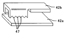
図7は、第1電極部材42aと第2電極部材42bとを示す斜視図である。
第1電極部材42a,第2電極部材42bは、板金などの導電性部材からなる板状形状である。第1電極部材42aの図中右側端部が、カバー部材43に保持されている。第2電極部材42bは、第1電極部材42aよりも鉛直下方に配置されており、第1電極部材42aよりも細くなっている。第2電極部材42bの図中左側端部側がカバー部材43に保持されており、カバー部材43に片持ち支持されている。第2電極部材42bの自由端側(図7右側端部)が、第1電極部材42aと平行に近接配置されている。第2電極部材42bの自由端側は、図7に示すように、二又に分かれており、それらの先端は、第1電極部材42a側に折り曲がって第1電極部材42a側へ突出する突出部47となっている。各突出部47の先端形状は、鋭角状となっており、後述するように、各突出部47が第1電極部材42aと点接触するような構成となっている。
FIG. 7 is a perspective view showing the first electrode member 42a and the second electrode member 42b.
The first electrode member 42a and the second electrode member 42b have a plate shape made of a conductive member such as a sheet metal. The right end portion of the first electrode member 42 a in the drawing is held by the cover member 43. The second electrode member 42b is disposed vertically below the first electrode member 42a and is thinner than the first electrode member 42a. The left end portion side of the second electrode member 42 b in the figure is held by the cover member 43 and is cantilevered by the cover member 43. The free end side (right end portion in FIG. 7) of the second electrode member 42b is disposed close to and parallel to the first electrode member 42a. As shown in FIG. 7, the free end side of the second electrode member 42b is divided into two parts, and the tips of the second electrode member 42b are bent toward the first electrode member 42a and protrude toward the first electrode member 42a. It becomes part 47. The tip shape of each protrusion 47 is an acute angle, and as will be described later, each protrusion 47 is in point contact with the first electrode member 42a.

また、図5に示すように、第1電極部材42aのカバー部材43に対して直交する方向の長さが、第2電極部材42bよりも長くなっており、少なくとも第2電極部材42bの突出部47付近においては、第1電極部材42aの方が大きい形状となっている。   As shown in FIG. 5, the length of the first electrode member 42a in the direction orthogonal to the cover member 43 is longer than that of the second electrode member 42b, and at least the protruding portion of the second electrode member 42b. In the vicinity of 47, the first electrode member 42a has a larger shape.

図8は、潤滑剤供給装置3の長手方向一端側を感光体側から見た図である。
図8に示すように、カバー部材43は、収納ケース3eにネジ101によりネジ止めされている。また、カバー部材43には、第1電極部材42aに電気的に接続された第1端子44aと、第2電極部材42bに電気的に接続された第2端子44bとがネジ45によりネジ止めされている。これら端子44a,44bに抵抗検知部42cが接続されている。
FIG. 8 is a view of one end in the longitudinal direction of the lubricant supply device 3 as viewed from the photosensitive member side.
As shown in FIG. 8, the cover member 43 is screwed to the storage case 3e with screws 101. The cover member 43 has a first terminal 44a electrically connected to the first electrode member 42a and a second terminal 44b electrically connected to the second electrode member 42b fixed by screws 45. ing. A resistance detector 42c is connected to these terminals 44a and 44b.

また、先の図4、図6に示すように、収納ケース3eの塗布ローラ3aと固形潤滑剤3bとの当接部よりも塗布ローラ回転方向下流側の側面には、潤滑剤保持部材3dの移動方向に延びる開口部31eが設けられている。この開口部31eは、固形潤滑剤3bの長手方向端部から所定距離、中央側に寄った箇所に設けられている。この開口部31eに潤滑剤保持部材3dに設けられた押し当て部31dが貫通している(図6参照)。また、カバー部材43には、カバー部材43で覆われた空間を、開口部31eが配置された空間と、第1電極部材42aおよび第2電極部材42bとが配置された空間とに仕切る仕切り手段としての仕切り壁43bが設けられている。   Also, as shown in FIGS. 4 and 6, the lubricant holding member 3d is disposed on the side surface of the storage case 3e on the downstream side of the application roller rotation direction with respect to the contact portion between the application roller 3a and the solid lubricant 3b. An opening 31e extending in the moving direction is provided. The opening 31e is provided at a predetermined distance from the end of the solid lubricant 3b in the longitudinal direction and at a position near the center. A pressing portion 31d provided on the lubricant holding member 3d passes through the opening 31e (see FIG. 6). Further, the cover member 43 has a partition means for partitioning the space covered by the cover member 43 into a space in which the opening 31e is disposed and a space in which the first electrode member 42a and the second electrode member 42b are disposed. A partition wall 43b is provided.

先の図4に示すように、検知用回転部材41は、カバー部材43の回転軸43cに回転自在に支持されており、板状形状をしている。検知用回転部材41の回転の支点(回転軸43c)よりも図中右側(固形潤滑剤長手方向中央部側)の先端が、押し当て部31dと対向している。検知用回転部材41の回転の支点(回転軸43c)よりも図中左側(固形潤滑剤長手方向端部側)の先端は、第2電極部材42bと対向している。この検知用回転部材41の回転の支点に対して図中左側の方が、図中右側よりも長くなっており、回転の支点に対して図中左側の方が、重量が重くなっている。このため、検知用回転部材41は、自重により図中反時計回り方向に回転する構成となっている。図4(a)に示すように、押し当て部31dが検知用回転部材41から離間した状態のときは、検知用回転部材41が仕切り壁43bの端部に突き当っており、自重による図中反時計回りの回動が規制されている。   As shown in FIG. 4, the detection rotation member 41 is rotatably supported by the rotation shaft 43 c of the cover member 43 and has a plate shape. The tip of the right side (solid lubricant longitudinal direction side) in the drawing from the rotation fulcrum (rotating shaft 43c) of the detection rotating member 41 faces the pressing portion 31d. The tip on the left side (solid lubricant longitudinal direction end side) in the drawing from the rotation fulcrum (rotating shaft 43c) of the detection rotating member 41 faces the second electrode member 42b. The left side in the figure is longer than the right side in the figure with respect to the rotation fulcrum of the detection rotating member 41, and the left side in the figure is heavier than the rotation fulcrum. For this reason, the detection rotating member 41 is configured to rotate counterclockwise in the figure by its own weight. As shown in FIG. 4A, when the pressing portion 31d is in a state of being separated from the detection rotating member 41, the detection rotating member 41 abuts against the end of the partition wall 43b. Counterclockwise rotation is restricted.

図4(a)に示すように、使用初期においては、潤滑剤保持部材3dに設けられた押し当て部31dは、検知用回転部材41から離間しており、検知用回転部材41は、仕切り壁43bの端部に突き当っている。このとき、検知用回転部材41の図中左側端部は、第2電極部材42bから離間しており、第2電極部材42bは所定のギャップを有して第1電極部材42aと対向している。よって、このとき、抵抗検知部42cにより、第1電極部材42aと第2電極部材42bとの間に電圧を印加しても第1電極部材42aと第2電極部材42bとの間に電流が流れず、電気抵抗値の測定が不能な状態である。   As shown in FIG. 4A, in the initial stage of use, the pressing portion 31d provided on the lubricant holding member 3d is separated from the detection rotary member 41, and the detection rotary member 41 is a partition wall. It hits the end of 43b. At this time, the left end portion of the detection rotating member 41 in the drawing is separated from the second electrode member 42b, and the second electrode member 42b has a predetermined gap and faces the first electrode member 42a. . Therefore, at this time, even if a voltage is applied between the first electrode member 42a and the second electrode member 42b by the resistance detector 42c, a current flows between the first electrode member 42a and the second electrode member 42b. In other words, the electrical resistance value cannot be measured.

固形潤滑剤3bが削られ潤滑剤が消費され固形潤滑剤3bの高さが低くなっていくと、潤滑剤保持部材3dが鉛直下方へ移動し、塗布ローラ3a側へ近づいていく。そして、固形潤滑剤3bの高さが所定値となると、潤滑剤保持部材3dに設けられた押し当て部31dが検知用回転部材41に当接する。さらに固形潤滑剤3bが削られ、高さが低くなると、押し当て部31dにより検知用回転部材41の図中右側端部が押され、検知用回転部材41が自重による回転方向と逆方向(図中時計回り)に回転する。さらに固形潤滑剤3bが削られていくと、検知用回転部材41がさらに時計回りに回転し、検知用回転部材41の図中左端が第2電極部材42bに当接する。さらに固形潤滑剤3bが削られ、検知用回転部材41がさらに時計回りに回転すると、検知用回転部材41が第2電極部材42bの自由端(図中右側端部)付近を第1電極部材42a側に押し込む。すると、第2電極部材42bの自由端が、第1電極部材42aに近づいていく。そして、図4(b)、図6(b)に示すように、潤滑剤の量が残り僅か(ニアエンド)となると、検知用回転部材41が所定角度回転し、第2電極部材42bの突出部47が第1電極部材42aと当接する。第2電極部材42bが第1電極部材42aに当接すると、第2電極部材42bと第1電極部材42aとが非導通状態から導通状態に切り替わる。これにより、抵抗検知部42cにより第1電極部材42aと第2電極部材42bとの間に電圧を印加すると、電極部材間に電流が流れる。その結果、抵抗検知部42cで電気抵抗値が計測され、検知用回転部材41が固形潤滑剤3bの消費に伴い回転したことを検知することができる。   When the solid lubricant 3b is scraped, the lubricant is consumed, and the height of the solid lubricant 3b is lowered, the lubricant holding member 3d moves vertically downward and approaches the application roller 3a side. When the height of the solid lubricant 3b reaches a predetermined value, the pressing portion 31d provided on the lubricant holding member 3d comes into contact with the detection rotating member 41. When the solid lubricant 3b is further shaved and the height is lowered, the right end portion of the rotation member 41 for detection in the drawing is pushed by the pressing portion 31d, and the rotation member 41 for detection is opposite to the rotation direction due to its own weight (see FIG. Rotate clockwise. As the solid lubricant 3b is further scraped, the detection rotating member 41 further rotates clockwise, and the left end of the detection rotating member 41 in the drawing contacts the second electrode member 42b. When the solid lubricant 3b is further shaved and the detection rotation member 41 further rotates clockwise, the detection rotation member 41 is located near the free end (right end portion in the drawing) of the second electrode member 42b. Push to the side. Then, the free end of the second electrode member 42b approaches the first electrode member 42a. Then, as shown in FIGS. 4B and 6B, when the amount of lubricant becomes small (near end), the detection rotating member 41 rotates by a predetermined angle, and the protruding portion of the second electrode member 42b. 47 contacts the first electrode member 42a. When the second electrode member 42b comes into contact with the first electrode member 42a, the second electrode member 42b and the first electrode member 42a are switched from the non-conductive state to the conductive state. Thereby, when a voltage is applied between the first electrode member 42a and the second electrode member 42b by the resistance detector 42c, a current flows between the electrode members. As a result, the electrical resistance value is measured by the resistance detection unit 42c, and it can be detected that the rotation member 41 for detection rotates with consumption of the solid lubricant 3b.

制御部100は、抵抗検知部42cの測定結果を監視しており、抵抗検知部42cが検知した電気抵抗値が所定値以下であることを検知したら、制御部100は、潤滑剤のニアエンドと判定する。そして、不図示の操作表示部に潤滑剤が残り少なくなくなった旨を報知し、ユーザーに固形潤滑剤の交換を促す。また、不図示の通信手段を用いて、サービスセンターに潤滑剤の交換が必要な旨を通知してもよい。   The control unit 100 monitors the measurement result of the resistance detection unit 42c. If the control unit 100 detects that the electrical resistance value detected by the resistance detection unit 42c is equal to or less than a predetermined value, the control unit 100 determines that the lubricant is near-end. To do. Then, an operation display unit (not shown) notifies the user that the remaining lubricant is low, and prompts the user to replace the solid lubricant. In addition, the service center may be notified that the lubricant needs to be replaced using a communication means (not shown).

潤滑剤の感光体1への塗布量は一定ではなく、感光体表面に形成された画像面積率などにより異なる。具体的に説明すると、潤滑剤が塗布された感光体表面に形成されたトナー像は、一次転写部で中間転写ベルト56に転写されるが、このとき、感光体表面の潤滑剤が、トナーとともに中間転写ベルトに移る場合がある。このため、高画像面積率の画像の方が、低画像面積率の画像に比べて、感光体表面の潤滑剤量が少なくなる。その結果、高画像面積率の画像の方が、感光体表面に供給される潤滑剤量が多くなるのである。このため、文字などの低画像面積率の画像を頻繁に出力するユーザーと、写真などの高画像面積率の画像を頻繁に出力するユーザーとで潤滑剤の減り具合が異なる。よって、本実施形態とは異なり、塗布ローラ3aの走行距離などの動作期間のみでニアエンドを判定する場合、すべての使用条件下で精度よくニアエンドを検知することができない。具体的に説明すると、潤滑剤の消費が多い使用条件のときにおける潤滑剤がニアエンドとなる塗布ローラ3aの走行距離を、ニアエンドの判定に用いた場合、潤滑剤の消費量が少ない使用条件で使用しているユーザーにおいては、固形潤滑剤が使いきれてない状態での潤滑剤の交換となってしまう。これとは逆に、潤滑剤の消費量が少ない使用条件のときにおける潤滑剤がニアエンドとなる塗布ローラ3aの走行距離を、ニアエンドの判定に用いた場合、潤滑剤の消費が多い使用条件のときにニアエンドが検知される前に潤滑剤が枯渇するおそれがある。   The amount of lubricant applied to the photoconductor 1 is not constant and varies depending on the image area ratio formed on the surface of the photoconductor. More specifically, the toner image formed on the surface of the photosensitive member coated with the lubricant is transferred to the intermediate transfer belt 56 at the primary transfer portion. At this time, the lubricant on the surface of the photosensitive member is combined with the toner. It may move to the intermediate transfer belt. For this reason, the amount of lubricant on the surface of the photoreceptor is smaller in the image with the high image area ratio than in the image with the low image area ratio. As a result, the amount of lubricant supplied to the surface of the photoreceptor increases in the image with a high image area ratio. For this reason, the degree of lubricant reduction differs between a user who frequently outputs an image with a low image area ratio such as characters and a user who frequently outputs an image with a high image area ratio such as a photograph. Therefore, unlike this embodiment, when the near end is determined only in the operation period such as the travel distance of the application roller 3a, the near end cannot be detected with high accuracy under all use conditions. More specifically, when the travel distance of the application roller 3a where the lubricant is near-end when the lubricant is consumed is used for the near-end determination, the lubricant is consumed under a usage condition where the lubricant consumption is small. For the user who is doing this, the lubricant must be replaced when the solid lubricant is not used up. On the other hand, when the travel distance of the application roller 3a where the lubricant is near-end when the consumption amount of the lubricant is low is used for the near-end determination, the lubricant consumption is high. The lubricant may run out before the near end is detected.

一方、本実施形態のように、残量検知部40により固形潤滑剤の高さに基づいて潤滑剤のニアエンドを検知することで、塗布ローラ3aの走行距離に基づいてニアエンドを検知する場合に比べて使用条件にかかわらず、精度よくニアエンドを検知することができる。   On the other hand, as in this embodiment, the remaining amount detection unit 40 detects the near end of the lubricant based on the height of the solid lubricant, so that the near end is detected based on the travel distance of the application roller 3a. The near end can be detected accurately regardless of the usage conditions.

また、本実施形態においては、検知用回転部材41の姿勢が、潤滑剤ニアエンドに対応する姿勢になるまで第1電極部材42aと第2電極部材42bとが非通電状態となっている。よって、電極部材間に電圧を印加しても電流が流れない。これにより、ニアエンド検知の度に電力が消費されることがないので、電力消費の低減を図ることができる。また、板金などの比較的安価な材料で構成される第1、第2電極部材42a,42bで、回転検知部42を構成することができ、回転検知部42を安価にすることができる。   In the present embodiment, the first electrode member 42a and the second electrode member 42b are in a non-energized state until the posture of the detection rotating member 41 becomes a posture corresponding to the lubricant near end. Therefore, no current flows even when a voltage is applied between the electrode members. Thereby, since power is not consumed every time near-end is detected, power consumption can be reduced. Further, the rotation detection unit 42 can be configured by the first and second electrode members 42a and 42b made of a relatively inexpensive material such as a sheet metal, and the rotation detection unit 42 can be made inexpensive.

また、本実施形態においては、固形潤滑剤3b長手方向両端部付近にそれぞれ、残量検知手段としての残量検知部40を設けている。よって、固形潤滑剤3bが長手方向で潤滑剤の消費量が異なった場合においても、潤滑剤の消費量が多い側の端部がニアエンドとなった時点で、潤滑剤の消費量が多い側の端部側に配置された検知用回転部材41が、潤滑剤ニアエンドに対応する姿勢になり、第2電極部材42bが第1電極部材42aと当接し導通する。これにより、固形潤滑剤3bが長手方向で潤滑剤の消費量が異なった場合においても、正確に潤滑剤のニアエンドを検知することができる。これにより、消費量が多い方の側の潤滑剤が枯渇して、感光体を保護できず、感光体表面が傷ついてしまうなどの不具合が発生するのを防止することができる。   Moreover, in this embodiment, the residual amount detection part 40 as a residual amount detection means is provided in the solid lubricant 3b vicinity of the longitudinal direction both ends, respectively. Therefore, even when the solid lubricant 3b has a different amount of lubricant in the longitudinal direction, when the end portion on the side with a large amount of lubricant consumption becomes near-end, The rotation member for detection 41 arranged on the end side is in a posture corresponding to the lubricant near end, and the second electrode member 42b comes into contact with the first electrode member 42a and becomes conductive. Thereby, even when the solid lubricant 3b has a different amount of lubricant consumption in the longitudinal direction, the near end of the lubricant can be accurately detected. As a result, it is possible to prevent the occurrence of problems such as exhaustion of the lubricant on the side where the amount of consumption is greater, protection of the photoreceptor, and damage to the surface of the photoreceptor.

また、本実施形態においては、残量検知部40を収納ケース3eの外に設けたので、飛散した潤滑剤粉が第1電極部材42aや第2電極部材42bに付着するのを抑制することができる。   In the present embodiment, since the remaining amount detection unit 40 is provided outside the storage case 3e, it is possible to suppress the scattered lubricant powder from adhering to the first electrode member 42a and the second electrode member 42b. it can.

感光体1中央部は、トナー像が形成され、形成されたトナー像が中間転写ベルト56などに転写されるときに感光体表面の潤滑剤が、トナーとともに中間転写ベルト56に移るため、感光体表面の潤滑剤量の減りが多い。一方、感光体表面の両端部付近は、通常、画像の余白部分に対応し、トナー像が形成されることはほとんどなく、感光体表面の潤滑剤の減りが少ない。従って、固形潤滑剤長手方向両端部付近の潤滑剤の感光体への塗布量が、固形潤滑剤長手方向中央部付近の塗布量よりも少なくなる。これに対し、塗布ローラ3aにより削られる潤滑剤量は、固形潤滑剤3b長手方向でほぼ均一である。このため、感光体表面に塗布されずに塗布ローラ3aに残る固形潤滑剤長手方向端部付近の潤滑剤量が、中央部付近に比べて多くなる。この塗布ローラ3aに残った潤滑剤は、収納ケース3eに堆積していくため、収納ケース3eの固形潤滑剤長手方向両端部付近に堆積する潤滑剤量は中央部に比べて多くなる。よって、本実施形態とは異なり、収納ケースの固形潤滑剤の長手方向端部付近に開口部31eを設けた場合は、開口部31eを通って飛散する潤滑剤が多くなる。その結果、第1電極部材42a、第2電極部材42bに付着する潤滑剤が多くなり、導通不良が生じ、語誤検知のおそれがある。一方、本実施形態のように、開口部31eを収納ケース3eの固形潤滑剤3bの長手方向端部から所定距離中央部よりに設けることで、開口部31eから飛散する潤滑剤の量を、開口部31eを収納ケース3eの固形潤滑剤長手方向端部に設けた場合に比べて抑制することができる。これにより、開口部31eから飛散した潤滑剤が、第1電極部材42aや第2電極部材42bに付着するのを抑制することができ、第2電極部材42bが第1電極部材42aに当接したときの導通不良を抑制することができる。これにより、潤滑剤ニアエンドの誤検知を抑制することができる。また、開口部31eからの潤滑剤の飛散を抑制するために、開口部31eはなるべく小さくするのが好ましい。   In the central portion of the photoreceptor 1, a toner image is formed, and when the formed toner image is transferred to the intermediate transfer belt 56 and the like, the lubricant on the surface of the photoreceptor is transferred to the intermediate transfer belt 56 together with the toner. There is much reduction in the amount of lubricant on the surface. On the other hand, the vicinity of both end portions of the surface of the photoconductor usually corresponds to a blank portion of the image, and a toner image is hardly formed, and the lubricant on the surface of the photoconductor is hardly reduced. Accordingly, the amount of lubricant applied to the photoconductor near both ends in the longitudinal direction of the solid lubricant is smaller than the amount of coating near the central portion of the solid lubricant in the longitudinal direction. On the other hand, the amount of lubricant scraped by the application roller 3a is substantially uniform in the longitudinal direction of the solid lubricant 3b. For this reason, the amount of lubricant in the vicinity of the end portion in the longitudinal direction of the solid lubricant remaining on the application roller 3a without being applied to the surface of the photosensitive member is larger than that in the vicinity of the central portion. Since the lubricant remaining on the application roller 3a accumulates in the storage case 3e, the amount of lubricant deposited in the vicinity of both ends of the solid lubricant in the longitudinal direction of the storage case 3e is larger than that in the central portion. Therefore, unlike the present embodiment, when the opening 31e is provided in the vicinity of the longitudinal end of the solid lubricant in the storage case, the amount of lubricant scattered through the opening 31e increases. As a result, the amount of lubricant adhering to the first electrode member 42a and the second electrode member 42b increases, resulting in poor conduction and the possibility of erroneous word detection. On the other hand, as in the present embodiment, the opening 31e is provided at a predetermined distance from the center in the longitudinal direction of the solid lubricant 3b of the storage case 3e so that the amount of lubricant scattered from the opening 31e can be reduced. Compared with the case where the part 31e is provided in the solid lubricant longitudinal direction edge part of the storage case 3e, it can suppress. Thereby, it is possible to suppress the lubricant scattered from the opening 31e from adhering to the first electrode member 42a and the second electrode member 42b, and the second electrode member 42b comes into contact with the first electrode member 42a. Continuity failure can be suppressed. Thereby, erroneous detection of the lubricant near end can be suppressed. Moreover, in order to suppress the scattering of the lubricant from the opening 31e, it is preferable to make the opening 31e as small as possible.

また、本実施形態においては、検知用回転部材41を設けて、押し当て部31dにより第2電極部材42bを第1電極部材側へ押して、第1電極部材42aに当接させている。これにより、検知部である第1電極部材42aと第2電極部材42bとの当接部を、開口部31eから離して設けることができる。従って、開口部31eから飛散した潤滑剤が、第1電極部材42aや第2電極部材42bに付着するのをより一層抑制することができる。   Further, in the present embodiment, the detection rotation member 41 is provided, and the second electrode member 42b is pushed toward the first electrode member by the pressing portion 31d and is brought into contact with the first electrode member 42a. Thereby, the contact part of the 1st electrode member 42a and the 2nd electrode member 42b which is a detection part can be provided away from the opening part 31e. Therefore, it is possible to further suppress the lubricant scattered from the opening 31e from adhering to the first electrode member 42a and the second electrode member 42b.

また、本実施形態においては、固形潤滑剤3bの消費に伴い、潤滑剤保持部材3dが鉛直方向下方へ移動するように構成し、検知用回転部材41の図4の右側端部を鉛直方向下方へ移動させ、第2電極部材42bに対向する検知用回転部材の端部(図4の左側端部)を鉛直上方に移動する構成としている。これにより、第1、第2電極部材を、固形潤滑剤3bと塗布ローラ3aとの当接部よりも鉛直上方に配置することができ、第1電極部材、第2電極部材に潤滑剤が付着するのを抑制することができる。   Further, in the present embodiment, the lubricant holding member 3d is configured to move downward in the vertical direction as the solid lubricant 3b is consumed, and the right end portion of the detection rotating member 41 in FIG. And the end portion (the left end portion in FIG. 4) of the detection rotating member facing the second electrode member 42b is moved vertically upward. Accordingly, the first and second electrode members can be arranged vertically above the contact portion between the solid lubricant 3b and the application roller 3a, and the lubricant adheres to the first electrode member and the second electrode member. Can be suppressed.

本実施形態においては、第1電極部材42aと第2電極部材42bとを鉛直方向に対向配置している。
また、第2電極部材42bの上面部は、第1電極部材42aと当接する箇所であるので、第2電極部材42bの上面部にはなるべく潤滑剤が付着しないようにする必要がある。本実施形態においては、第2電極部材42bの第1電極部材と当接する固形潤滑剤長手方向中央側端部付近を、第1電極部材42aに近接配置している。これにより、第2電極部材42bの固形潤滑剤長手方向中央側端部付近と第1電極部材42aとの隙間が狭くなり、第2電極部材42bの固形潤滑剤長手方向中央側端部付近の上面部に潤滑剤が付着するのを抑制することができる。
In the present embodiment, the first electrode member 42a and the second electrode member 42b are disposed to face each other in the vertical direction.
Moreover, since the upper surface part of the 2nd electrode member 42b is a location contact | abutted with the 1st electrode member 42a, it is necessary to make a lubricant adhere to the upper surface part of the 2nd electrode member 42b as much as possible. In the present embodiment, the vicinity of the end portion on the center side in the longitudinal direction of the solid lubricant contacting the first electrode member of the second electrode member 42b is disposed close to the first electrode member 42a. Thereby, the clearance gap between the solid lubricant longitudinal direction center side edge part of the 2nd electrode member 42b and the 1st electrode member 42a becomes narrow, and the upper surface near the solid lubricant longitudinal direction center side edge part of the 2nd electrode member 42b It can suppress that a lubricant adheres to a part.

図9は、従来の残量検知部の一例を示す図である。
図9に示す従来技術においては、板状の第1電極部材42aの鉛直上方に板状の第2電極部材42bが配置されたものであり、第1電極部材42aの上面と第2電極部材42bの下面とが当接(面接触)することで、ニアエンドが検知されるものである。このように、鉛直方向に板状の電極部材を対向配置させた構成においては、第1電極部材42a,第2電極部材42bの上面部は、飛散した潤滑剤などが堆積するおそれがある。押し当て部31dで第2電極部材42bを第1電極部材42a側へ押し込んで、第2電極部材42bの下面を、第1電極部材の上面に面接触させるとき、図10に示すように第1電極部材42aの上面に堆積した堆積物Tが、第2電極部材42bと第1電極部材42aとの間に挟まり、第2電極部材42bと第1電極部材42aとの間に接触不良が生じるおそれがある。
FIG. 9 is a diagram illustrating an example of a conventional remaining amount detection unit.
In the prior art shown in FIG. 9, a plate-like second electrode member 42b is arranged vertically above the plate-like first electrode member 42a. The upper surface of the first electrode member 42a and the second electrode member 42b are arranged. The near end is detected by abutting (surface contact) with the lower surface. As described above, in the configuration in which the plate-like electrode members are arranged to face each other in the vertical direction, scattered lubricant or the like may be deposited on the upper surface portions of the first electrode member 42a and the second electrode member 42b. When the second electrode member 42b is pushed toward the first electrode member 42a by the pressing portion 31d and the lower surface of the second electrode member 42b is brought into surface contact with the upper surface of the first electrode member, the first electrode as shown in FIG. The deposit T deposited on the upper surface of the electrode member 42a may be sandwiched between the second electrode member 42b and the first electrode member 42a, resulting in poor contact between the second electrode member 42b and the first electrode member 42a. There is.

しかし、本実施形態においては、鉛直下方に配置される第2電極部材42bの自由端を第1電極部材42aへ突出させて突出部47を設け、この突出部47を第1電極部材42aに当接させる。このように、第1電極部材42aと当接する箇所を、第2電極部材42bの上面から突出させることで、突出部に潤滑剤などが堆積するのを抑制することができる。これにより、第1電極部材42aに確実に第2電極部材42bを当接させることができ、良好にニアエンドの検知を行うことができる。   However, in the present embodiment, the free end of the second electrode member 42b arranged vertically downward is protruded to the first electrode member 42a to provide a protrusion 47, and the protrusion 47 is brought into contact with the first electrode member 42a. Make contact. In this way, by causing the portion that contacts the first electrode member 42a to protrude from the upper surface of the second electrode member 42b, it is possible to suppress the accumulation of lubricant or the like on the protruding portion. Thereby, the 2nd electrode member 42b can be reliably made to contact | abut to the 1st electrode member 42a, and a near end can be detected favorably.

さらに、本実施形態においては、第1電極部材42aと当接する突出部47の先端を点形状にしているので、突出部47の先端に潤滑剤などが堆積するのを防止することができる。これにより、第1電極部材42aに確実に第2電極部材42bを当接させることができ、良好にニアエンドの検知を行うことができる。   Furthermore, in the present embodiment, since the tip of the protrusion 47 that contacts the first electrode member 42a has a dot shape, it is possible to prevent lubricant and the like from being deposited on the tip of the protrusion 47. Thereby, the 2nd electrode member 42b can be reliably made to contact | abut to the 1st electrode member 42a, and a near end can be detected favorably.

また、第1電極部材42aの下面の第2電極部材42bと当接する箇所に潤滑剤が付着していても、先の図9、図10に示すように、板状の電極部材同士が当接するものに比べて、突出部47で容易に潤滑剤を押し退けることができる。
先の図9、図10に示した従来技術にいては、ある程度広い範囲で一斉に電極部材同士が接触するため、付着した潤滑剤が当接範囲から逃げるスペースがない。また、ある程度広い範囲で電極部材同士が接触するため、当接圧が低く、付着した潤滑剤を押し退けるほどの力を発揮できない。一方、本実施形態においては、第1電極部材42aに突出部47が当接するとき、突出部47の周囲には突出部47により押された潤滑剤が逃げるためのスペースが十分にある。また、第1電極部材42aとの当接圧が高く、第1電極部材42aに付着した潤滑剤を押し退けるのに十分な力を得ることができる。これにより、第1電極部材42aの下面の第2電極部材42bと当接する箇所に潤滑剤が付着していても、突出部47で容易に潤滑剤を押し退けることができるのである。これにより、第1電極部材42aに確実に第2電極部材42bを当接させることができる。
Further, even if the lubricant adheres to the portion of the lower surface of the first electrode member 42a that contacts the second electrode member 42b, the plate-like electrode members contact each other as shown in FIGS. The lubricant can be easily pushed away by the projecting portion 47 as compared with the above.
In the prior art shown in FIGS. 9 and 10, since the electrode members are in contact with each other in a wide range, there is no space for the adhered lubricant to escape from the contact range. Further, since the electrode members are in contact with each other over a wide range, the contact pressure is low, and the force enough to push away the adhered lubricant cannot be exhibited. On the other hand, in the present embodiment, when the protruding portion 47 comes into contact with the first electrode member 42a, there is sufficient space around the protruding portion 47 for the lubricant pushed by the protruding portion 47 to escape. Further, the contact pressure with the first electrode member 42a is high, and a sufficient force can be obtained to push away the lubricant adhering to the first electrode member 42a. As a result, even if the lubricant adheres to the portion of the lower surface of the first electrode member 42a that contacts the second electrode member 42b, the lubricant can be easily pushed away by the protruding portion 47. Thereby, the 2nd electrode member 42b can be reliably made to contact | abut to the 1st electrode member 42a.

また、第2電極部材42bの自由端は、鉛直方向に対して平行に第1電極部材へ移動するのではなく、自由端は、第2電極部材42bの固定端を支点にした略円弧状の軌跡を取りながら、第1電極部材42aに近づいていく。よって、第2電極部材42bの自由端に突出部47を設けることで、第1電極部材42aに当接する際に、突出部47は、僅かではあるが、第1電極部材42aの下面と平行な方向にも移動する。これにより、第1電極部材42aの下面についた付着物を掻き落とす効果も期待できる。   In addition, the free end of the second electrode member 42b does not move to the first electrode member in parallel to the vertical direction, but the free end has a substantially arc shape with the fixed end of the second electrode member 42b as a fulcrum. It approaches the 1st electrode member 42a, taking a locus. Therefore, by providing the protrusion 47 at the free end of the second electrode member 42b, the protrusion 47 is slightly parallel to the lower surface of the first electrode member 42a when contacting the first electrode member 42a. Move also in the direction. Thereby, the effect of scraping off the deposits on the lower surface of the first electrode member 42a can also be expected.

また、本実施形態においては、第2電極部材42bの自由端側を、二又に分けそれぞれの先端に突出部47を設けて、複数の突出部47を第1電極部材42aに当接させる構成としている。このように、突出部47を複数設けることで、ある突出部47が何らかの要因で第1電極部材と接触不良が生じたとしても、その他の突出部のいずれかが、第1電極部材42aと良好に接触することができる。これにより、第1電極部材42aに確実に第2電極部材42bを当接させることができる。   Further, in the present embodiment, the free end side of the second electrode member 42b is divided into two parts, and the protrusions 47 are provided at the respective tips, and the plurality of protrusions 47 are brought into contact with the first electrode member 42a. It is said. Thus, by providing a plurality of protrusions 47, even if a certain protrusion 47 has poor contact with the first electrode member for some reason, any of the other protrusions is as good as the first electrode member 42a. Can contact. Thereby, the 2nd electrode member 42b can be reliably made to contact | abut to the 1st electrode member 42a.

また、本実施形態においては、鉛直下方に配置される第2電極部材に突出部を設けているが、鉛直上方に配置される第1電極部材42aに設けてもよい。この場合は、潤滑剤などが堆積した第2電極部材の上面に突出部を当接させることになる。上述したように、突出部47で容易に潤滑剤を押し退けることができるので、第2電極部材42bの上面の堆積した潤滑剤などの堆積物を突出部47により押し退けて、突出部を第2電極部材42bに当接させることができる。   Moreover, in this embodiment, although the protrusion part is provided in the 2nd electrode member arrange | positioned vertically downward, you may provide in the 1st electrode member 42a arrange | positioned vertically upward. In this case, the protrusion is brought into contact with the upper surface of the second electrode member on which the lubricant or the like is deposited. As described above, since the lubricant can be easily pushed away by the protruding portion 47, deposits such as lubricant deposited on the upper surface of the second electrode member 42b are pushed away by the protruding portion 47, and the protruding portion is moved to the second electrode. It can be brought into contact with the member 42b.

また、突出部47は、上述に限らず、例えば、図11に示すように、板状の第2電極部材42bの自由端側を第1電極部材42aに折り曲げて形成したものでもよい。また、図12に示すように、板状の第2電極部材42bに、針状の突出部47を一つ設けた構成や、図13に示すように、3つ以上の針状の突出部47を設けた構成でもよい。また、図14に示すように、第2電極部材42bの自由端側を、のこぎり形状にして、突出部47を複数形成してもよい。また、図15に示すように、第2電極部材42bの自由端側の短手方向両端を、第1電極部材42a側に折り曲げ、これら折り曲げ部の先端をのこぎり形状にして、突出部47を複数形成してもよい。   Further, the protrusion 47 is not limited to the above, and may be formed by bending the free end side of the plate-like second electrode member 42b to the first electrode member 42a as shown in FIG. 11, for example. Further, as shown in FIG. 12, the plate-like second electrode member 42b is provided with one needle-like protrusion 47, or as shown in FIG. 13, three or more needle-like protrusions 47 are provided. The structure which provided may be sufficient. Further, as shown in FIG. 14, a plurality of protruding portions 47 may be formed by making the free end side of the second electrode member 42b into a saw shape. In addition, as shown in FIG. 15, both ends of the second electrode member 42b in the short side direction on the free end side are bent toward the first electrode member 42a, and the ends of these bent portions are saw-shaped so that a plurality of protruding portions 47 are provided. It may be formed.

また、図16に示すように、第1電極部材42aと第2電極部材42bとの間の突出部47の移動範囲に、突出部47を清掃する清掃部材としての清掃ブラシ48を配置してもよい。このように、清掃ブラシ48を設けることで、突出部47が、清掃ブラシ48のブラシ繊維に摺擦しながら第1電極部材側へ移動し、突出部47に付着した潤滑剤などを除去することができる。これにより、第1電極部材42aに確実に第2電極部材42bを当接させることができ、精度よくニアエンドを検知することができる。   Further, as shown in FIG. 16, a cleaning brush 48 as a cleaning member for cleaning the protrusion 47 is disposed in the movement range of the protrusion 47 between the first electrode member 42 a and the second electrode member 42 b. Good. Thus, by providing the cleaning brush 48, the protrusion 47 moves to the first electrode member side while rubbing against the brush fibers of the cleaning brush 48, and the lubricant and the like attached to the protrusion 47 is removed. Can do. Thereby, the 2nd electrode member 42b can be reliably made to contact | abut to the 1st electrode member 42a, and a near end can be detected accurately.

また、この場合においては、突出部47を有する第2電極部材42bを、鉛直下方側に設けるのが好ましい。これは、第2電極部材42bを鉛直上方に設けた場合、清掃ブラシ48のより掻き落とされた付着物が、第1電極部材42aの突出部47との当接面である第1電極部材42aの上面部に付着してしまうおそれがある。一方、突出部47を有する第2電極部材42bを、鉛直下方側に設けた場合、清掃ブラシ48のより掻き落とされた付着物が、第1電極部材42aの突出部47との当接面(下面)に付着することはない。これにより、第1電極部材42aの突出部47との当接面が汚れるのを防止することができ、第1電極部材42aに確実に第2電極部材42bを当接させることができる。   In this case, it is preferable to provide the second electrode member 42b having the protrusion 47 on the vertically lower side. This is because, when the second electrode member 42b is provided vertically upward, the adhered material scraped off by the cleaning brush 48 is the first electrode member 42a that is a contact surface with the protruding portion 47 of the first electrode member 42a. There is a risk of adhering to the upper surface of the substrate. On the other hand, when the 2nd electrode member 42b which has the protrusion part 47 is provided in the perpendicular downward side, the deposit | attachment scraped off by the cleaning brush 48 is a contact surface with the protrusion part 47 of the 1st electrode member 42a ( It will not adhere to the lower surface. Thereby, it can prevent that the contact surface with the protrusion part 47 of the 1st electrode member 42a gets dirty, and can make the 2nd electrode member 42b contact | abut to the 1st electrode member 42a reliably.

また、本実施形態においては、第1電極部材42aの水平投影面積(鉛直上方から見たときの面積)を第2電極部材42bの自由端(突出部47)付近の水平投影面積よりも大きくしている。これにより、図5の一点鎖線に示すように、鉛直真上からみたとき、第1電極部材42aで第2電極部材42bの自由端近傍が隠された形となる。その結果、丁度、第1電極部材42aが庇のような働きをし、鉛直上方から落下してきた潤滑剤を第1電極部材の上面部で受けることができる。これにより、第2電極部材42bの上面部に潤滑剤が付着するのを抑制することができる。なお、第1電極部材42aの上面部に潤滑剤が堆積しても第1電極部材と第2電極部材との導通状態になんら影響を与えることはない。   In the present embodiment, the horizontal projection area of the first electrode member 42a (the area when viewed from above in the vertical direction) is made larger than the horizontal projection area in the vicinity of the free end (projecting portion 47) of the second electrode member 42b. ing. As a result, as shown by the alternate long and short dash line in FIG. 5, when viewed from directly above, the first electrode member 42a hides the vicinity of the free end of the second electrode member 42b. As a result, the first electrode member 42a acts just like a ridge, and the lubricant that has dropped from vertically above can be received by the upper surface of the first electrode member. Thereby, it can suppress that a lubricant adheres to the upper surface part of the 2nd electrode member 42b. Note that even if the lubricant is deposited on the upper surface portion of the first electrode member 42a, the conductive state between the first electrode member and the second electrode member is not affected at all.

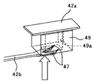
また、図17に示すように、突出部47の周囲を囲んで突出部47を遮蔽する遮蔽部材49を設けて、突出部47や、第1電極部材42aの突出部47と当接する箇所に潤滑剤などが付着するのを抑制するようにしてもよい。
図17は、遮蔽部材49を設けた実施例を示す要部分解図である。
図に示すように、遮蔽部材49は、絶縁性のスポンジ部材などの変形しやすい材質で構成し、中央部に貫通穴49aが形成されている。図18に示すように、遮蔽部材49の上面は、第1電極部材42aの下面に粘着テープなどで固定する。また、第2電極部材42bの突出部47が、貫通穴49aに入り込むように遮蔽部材49を配置する。
Further, as shown in FIG. 17, a shielding member 49 that surrounds the projection 47 and shields the projection 47 is provided to lubricate the projection 47 and the portion that contacts the projection 47 of the first electrode member 42a. You may make it suppress that an agent etc. adhere.
FIG. 17 is an exploded view of the main part showing an embodiment in which a shielding member 49 is provided.
As shown in the figure, the shielding member 49 is made of an easily deformable material such as an insulating sponge member, and a through hole 49a is formed at the center. As shown in FIG. 18, the upper surface of the shielding member 49 is fixed to the lower surface of the first electrode member 42a with an adhesive tape or the like. Further, the shielding member 49 is arranged so that the protruding portion 47 of the second electrode member 42b enters the through hole 49a.

固形潤滑剤3bの消費に伴い検知用回転部材41により第2電極部材42bが第1電極部材42aへ押されると、第2電極部材42bは、スポンジなどの変形しやすい材質からなる遮蔽部材49を押しつぶしながら、第1電極部材42a側へと移動する。そして、遮蔽部材49の貫通穴49a入り込むように設けられた突出部47が、第1電極部材42aと当接する。このとき、遮蔽部材49により、突出部47を第1電極部材から引き離す方向の復元力が働く。しかし、各電極部材42a,42bの剛性を遮蔽部材の剛性よりも十分に大きくすることで、上記復元力により各電極部材42a,42bが、突出部47を第1電極部材から引き離す方向に変形するのを防止することができる。これにより、突出部47を良好に第1電極部材42aに当接させることができる。また、突出部47の第2電極部材からの突出量は、変形後の遮蔽部材49の厚みに合わせて設定することで、突出部47を良好に第1電極部材42aに当接させることができる。   When the second electrode member 42b is pushed to the first electrode member 42a by the detection rotating member 41 as the solid lubricant 3b is consumed, the second electrode member 42b has a shielding member 49 made of a material that is easily deformed, such as sponge. While squeezing, it moves to the first electrode member 42a side. And the protrusion part 47 provided so that it may enter through-hole 49a of the shielding member 49 contact | abuts with the 1st electrode member 42a. At this time, the shielding member 49 exerts a restoring force in the direction of pulling the protruding portion 47 away from the first electrode member. However, by making the rigidity of the electrode members 42a and 42b sufficiently greater than the rigidity of the shielding member, the electrode members 42a and 42b are deformed in the direction of separating the protrusion 47 from the first electrode member by the restoring force. Can be prevented. Thereby, the protrusion part 47 can be made to contact | abut to the 1st electrode member 42a favorably. Moreover, the protrusion amount of the protrusion 47 from the second electrode member is set according to the thickness of the shield member 49 after the deformation, whereby the protrusion 47 can be brought into good contact with the first electrode member 42a. .

このように遮蔽部材49を設けることで、突出部47や、第1電極部材42aの突出部47と当接する箇所に潤滑剤などが付着するのを抑制することができ、潤滑剤付着による誤検知を抑制することができる。   By providing the shielding member 49 in this way, it is possible to suppress the adhesion of the lubricant or the like to the protruding portion 47 or the location where the protruding portion 47 of the first electrode member 42a comes into contact. Can be suppressed.

また、本実施形態においては、図4に示したように、仕切り壁43bにより、カバー部材43で覆われた空間を、開口部31eが設けられた空間と、各電極部材が設けられた空間とに仕切っている。これにより、開口部31eから進入してきた潤滑剤粉が、第1電極部材42a,第2電極部材42bに付着するのをより一層抑制することができる。また、カバー部材43と仕切り壁43bとを樹脂で一体成形するのが好ましい。これにより、カバー部材43と仕切り壁43bとを別部材で構成した場合に比べて、部品点数を削減でき、装置を安価にすることができる。また、収納ケース3eに仕切り壁43bを設けてもよい。この場合も、収納ケース3eと仕切り壁43bとを樹脂で一体成形することで、部品点数を削減でき、装置を安価にすることができる。また、カバー部材43、収納ケース3eそれぞれに仕切り壁を設けて、組み合わせることで、カバー部材43で覆われた空間を、開口部31eが設けられた空間と、各電極部材が設けられた空間とに仕切ってもよい。   In the present embodiment, as shown in FIG. 4, the space covered with the cover member 43 by the partition wall 43 b is divided into a space in which the opening 31 e is provided, and a space in which each electrode member is provided. It is divided into. Thereby, it is possible to further suppress the lubricant powder entering from the opening 31e from adhering to the first electrode member 42a and the second electrode member 42b. Moreover, it is preferable to integrally mold the cover member 43 and the partition wall 43b with resin. Thereby, compared with the case where the cover member 43 and the partition wall 43b are comprised by another member, a number of parts can be reduced and an apparatus can be made cheap. Moreover, you may provide the partition wall 43b in the storage case 3e. Also in this case, by integrally molding the storage case 3e and the partition wall 43b with resin, the number of parts can be reduced and the apparatus can be made inexpensive. In addition, a partition wall is provided in each of the cover member 43 and the storage case 3e and combined to form a space covered with the cover member 43, a space in which the opening 31e is provided, and a space in which each electrode member is provided. You may partition into.

また、本実施形態においては、カバー部材43で開口部31eおよび第1電極部材42a,第2電極部材42bを覆っている。これにより、開口部31eから潤滑剤供給装置3外へ潤滑剤が飛散するのを抑制することができ、装置が汚れるのを抑制することができる。また、飛散トナーなどが、第1電極部材42aや第2電極部材42bに付着するのを抑制することができ、電極部材間に導通不良が生じるのを抑制することができる。   In the present embodiment, the cover member 43 covers the opening 31e, the first electrode member 42a, and the second electrode member 42b. Thereby, it can suppress that a lubricant scatters from the opening part 31e out of the lubricant supply apparatus 3, and can suppress that an apparatus becomes dirty. Moreover, scattering toner or the like can be prevented from adhering to the first electrode member 42a or the second electrode member 42b, and the occurrence of poor conduction between the electrode members can be suppressed.

また、本実施形態においては、検知用回転部材41の自重による回転方向を、固形潤滑剤3bの消費に伴い回転する方向と逆方向にしている。本実施形態と異なり、検知用回転部材41の自重による回転方向を、固形潤滑剤3bの消費に伴い回転する方向と同方向にした場合、検知用回転部材が自重により回転しないように規制する規制部材をスプリングなどの付勢手段により構成し、自重による回動方向と逆方向に付勢しておく必要がある。かかる構成の場合、潤滑剤保持部材3dに設けられた押し当て部31dが、検知用回転部材41を押して、検知用回転部材41を潤滑剤の消費に伴い回転させると、スプリングの付勢力が増していく。その結果、固形潤滑剤3bの残量がニアエンド(検知用回転部材41の回転角度が所定角度)に近づくにつれて、固形潤滑剤3bの塗布ローラ3aに対する当接圧が減少し、感光体1への潤滑剤供給量が低下してしまう。   Moreover, in this embodiment, the rotation direction by the dead weight of the rotation member 41 for a detection is made into the reverse direction with the direction rotated with consumption of the solid lubricant 3b. Unlike the present embodiment, when the rotation direction due to the weight of the detection rotation member 41 is the same as the rotation direction due to the consumption of the solid lubricant 3b, the restriction that restricts the detection rotation member from rotating due to its own weight. It is necessary that the member is constituted by an urging means such as a spring and urged in the direction opposite to the rotating direction due to its own weight. In such a configuration, when the pressing portion 31d provided on the lubricant holding member 3d pushes the detection rotating member 41 and rotates the detection rotating member 41 as the lubricant is consumed, the biasing force of the spring increases. To go. As a result, as the remaining amount of the solid lubricant 3b approaches the near end (the rotation angle of the detection rotation member 41 is a predetermined angle), the contact pressure of the solid lubricant 3b with respect to the application roller 3a decreases, and Lubricant supply amount will decrease.

一方、本実施形態のように、検知用回転部材41の自重による回転方向を、固形潤滑剤3bの消費に伴い回転する方向と逆方向にすることで、上述のようなスプリングが不要となる。よって、固形潤滑剤3bの塗布ローラ3aに対する当接圧の変動を抑えることができる。これにより、検知用回転部材41の自重による回転方向を、上記固形潤滑剤の消費に伴い回転する方向と同方向にした場合に比べて感光体1への潤滑剤供給量の変動を抑えることができる。   On the other hand, as described in the present embodiment, the above-described spring is not required by setting the rotation direction due to the weight of the rotation member 41 for detection to be opposite to the rotation direction with the consumption of the solid lubricant 3b. Therefore, the fluctuation | variation of the contact pressure with respect to the application roller 3a of the solid lubricant 3b can be suppressed. As a result, fluctuations in the amount of lubricant supplied to the photosensitive member 1 can be suppressed as compared with the case where the rotation direction due to the weight of the detection rotation member 41 is the same as the rotation direction accompanying the consumption of the solid lubricant. it can.

また、本実施形態においては、カバー部材43に第1電極部材42a,第2電極部材42b,検知用回転部材41を位置決め保持している。このように、同一の部材に第1電極部材42a,第2電極部材42b,検知用回転部材41を位置決め保持することで、部品公差を最小限に抑えることができる。よって、第1電極部材42a,第2電極部材42b,検知用回転部材41のそれぞれの位置関係を精度よく出すことができる。これにより、固形潤滑剤3bがニアエンド状態のときに、確実に第2電極部材42bを第1電極部材42aに当接させることができ、精度よく潤滑剤のニアエンド状態を検知することができる。また、カバー部材43を収納ケース3eから取り外すだけで、残量検知部40を、潤滑剤供給装置3から取り外すことができ、残量検知部40の交換作業を容易に行うことができる。   In the present embodiment, the first electrode member 42a, the second electrode member 42b, and the detection rotating member 41 are positioned and held on the cover member 43. Thus, by positioning and holding the first electrode member 42a, the second electrode member 42b, and the detection rotating member 41 on the same member, component tolerance can be minimized. Therefore, each positional relationship of the 1st electrode member 42a, the 2nd electrode member 42b, and the rotation member 41 for detection can be taken out accurately. Thus, when the solid lubricant 3b is in the near-end state, the second electrode member 42b can be reliably brought into contact with the first electrode member 42a, and the near-end state of the lubricant can be detected with high accuracy. Moreover, the remaining amount detection part 40 can be removed from the lubricant supply apparatus 3 only by removing the cover member 43 from the storage case 3e, and the replacement work of the remaining amount detection part 40 can be performed easily.

図6(b)に示すように潤滑剤塗布動作中のときは塗布ローラ3aが回転して固形潤滑剤3bを摺擦している。このため、固形潤滑剤3bは塗布ローラ3aの表面移動方向(図中左側)に力を受ける。潤滑剤保持部材3dは、収納ケース3e内部で移動できるように構成する必要があるため、収納ケース3eに対してある程度のガタがある状態で収納ケース3eに収納されている。このため、固形潤滑剤3bは塗布ローラ3aの表面移動方向(図中左側)に力を受けると、潤滑剤保持部材3dが、塗布ローラ3aの固形潤滑剤を摺擦する方向(図中左側)に移動する。その結果、残量検知部40を、本実施形態とは異なり、収納ケース3eにおける塗布ローラ3aと固形潤滑剤3bとの当接部よりも塗布ローラ3a回転方向上流側の側面に設けた場合、潤滑剤保持部材3dが、塗布ローラ3aの固形潤滑剤を摺擦する方向(図中左側)に移動すると、押し当て部31dが、検知用回転部材41と当接しないおそれがある。その結果、検知用回転部材41が回転しないおそれがある。   As shown in FIG. 6B, during the lubricant application operation, the application roller 3a rotates to rub the solid lubricant 3b. For this reason, the solid lubricant 3b receives a force in the surface movement direction (left side in the figure) of the application roller 3a. Since the lubricant holding member 3d needs to be configured to be movable inside the storage case 3e, the lubricant holding member 3d is stored in the storage case 3e with a certain amount of play relative to the storage case 3e. Therefore, when the solid lubricant 3b receives a force in the surface movement direction (left side in the figure) of the application roller 3a, the lubricant holding member 3d slides the solid lubricant on the application roller 3a (left side in the figure). Move to. As a result, unlike the present embodiment, the remaining amount detection unit 40 is provided on the side surface on the upstream side in the rotation direction of the application roller 3a with respect to the contact portion between the application roller 3a and the solid lubricant 3b in the storage case 3e. When the lubricant holding member 3d moves in a direction (left side in the figure) for rubbing the solid lubricant of the application roller 3a, the pressing portion 31d may not come into contact with the detection rotating member 41. As a result, there is a possibility that the detection rotating member 41 does not rotate.

一方、本実施形態のように、収納ケース3eにおける塗布ローラ3aと固形潤滑剤3bとの当接部よりも塗布ローラ3a回転方向下流側の側面に設けることで、押し当て部31dを確実に検知用回転部材41に当接させることができる。よって、確実にニアエンド状態を検知することができる。また、潤滑剤保持部材3d、固形潤滑剤3bが、塗布ローラ3aの表面移動方向(図中左側)に移動し、開口部31eを塞ぐことができる。これにより、収納ケース3e内に堆積した潤滑剤粉が、開口部31eから飛散するのを抑制することができる。   On the other hand, as in the present embodiment, the pressing portion 31d is reliably detected by providing it on the side surface on the downstream side in the rotation direction of the coating roller 3a with respect to the contact portion between the coating roller 3a and the solid lubricant 3b in the storage case 3e. The rotating member 41 can be brought into contact. Therefore, the near-end state can be reliably detected. In addition, the lubricant holding member 3d and the solid lubricant 3b can move in the surface movement direction (left side in the drawing) of the application roller 3a to block the opening 31e. Thereby, it is possible to suppress the lubricant powder accumulated in the storage case 3e from being scattered from the opening 31e.

また、本実施形態においては、潤滑剤が枯渇する直前の所謂固形潤滑剤のエンド状態ではなく、所定回数感光体1表面に潤滑剤を供給可能な量の残量(ニアエンド状態)を検知するようにしている。潤滑剤のエンド状態を検知する場合、検知後に画像形成動作を行うと、潤滑剤枯渇による不具合が生じるため、潤滑剤の交換作業が完了するまで画像形成動作を禁止する必要があり、ダウンタイムが生じてしまう。   Further, in the present embodiment, not the so-called solid lubricant end state immediately before the lubricant is exhausted but the remaining amount (near end state) of an amount capable of supplying the lubricant to the surface of the photoreceptor 1 a predetermined number of times is detected. I have to. When detecting the end state of the lubricant, if the image forming operation is performed after the detection, there will be a problem due to the exhaustion of the lubricant, so it is necessary to prohibit the image forming operation until the lubricant replacement operation is completed, and downtime will be reduced. It will occur.

これに対し、本実施形態においては、潤滑剤のニアエンド状態を検知しているので、検知後の所定回数、画像形成動作を行っても、感光体表面に潤滑剤を塗布でき、感光体表面を保護できる。これにより、検知後から固形潤滑剤の準備が整い交換作業を開始するまでの間も、画像形成動作を行うことができ、装置のダウンタイムが生じるのを抑制することができる。また、準備が整うまでの間に、所定回数以上の画像形成動作が行われると、潤滑剤が枯渇してしまい、潤滑剤枯渇による不具合が出てしまう。よって、ニアエンドを検知したら、塗布ローラ3aの走行距離(回転回数)や、画像形成動作回数などを監視する。そして、塗布ローラ3aの走行距離や画像形成動作回数が所定値となったら、潤滑剤のエンド状態と判定して、画像形成動作を禁止する。   On the other hand, in this embodiment, since the near-end state of the lubricant is detected, the lubricant can be applied to the surface of the photoconductor even if the image forming operation is performed a predetermined number of times after the detection. Can protect. Accordingly, the image forming operation can be performed from the detection until the solid lubricant is ready and the replacement operation is started, and the downtime of the apparatus can be suppressed. Further, if the image forming operation is performed a predetermined number of times or more before preparation is completed, the lubricant is exhausted, and a problem due to the exhaustion of the lubricant occurs. Therefore, when the near end is detected, the travel distance (number of rotations) of the application roller 3a, the number of image forming operations, and the like are monitored. When the travel distance of the application roller 3a and the number of image forming operations reach predetermined values, it is determined that the lubricant is in an end state and the image forming operation is prohibited.

潤滑剤塗布動作中のときは塗布ローラ3aが回転して固形潤滑剤を摺擦している。このため、固形潤滑剤3bは塗布ローラ3aの表面移動方向(図中左側)に力を受ける。潤滑剤保持部材3dは、収納ケース3e内部で移動できるように構成する必要があるため、収納ケース3eに対してある程度のガタがある状態で収納ケース3eに収納されている。このため、固形潤滑剤3bは塗布ローラ3aの表面移動方向(図中左側)に力を受けると、潤滑剤保持部材3dが、塗布ローラ3aの固形潤滑剤を摺擦する方向(図6の反時計回り)に傾くおそれがある。本実施形態においては、図6に示すように、押し当て部31dは、潤滑剤保持部材3dの塗布ローラ3a回転方向下流側の側面に設けている。このため、潤滑剤保持部材3dが傾くとまだ固形潤滑剤の量が十分にある状態で押し当て部31dが検知用回転部材を押し込み、電極部材間が導通し、制御部100がニアエンドと誤検知する場合がある。   During the lubricant application operation, the application roller 3a rotates to rub the solid lubricant. For this reason, the solid lubricant 3b receives a force in the surface movement direction (left side in the figure) of the application roller 3a. Since the lubricant holding member 3d needs to be configured to be movable inside the storage case 3e, the lubricant holding member 3d is stored in the storage case 3e with a certain amount of play relative to the storage case 3e. Therefore, when the solid lubricant 3b receives a force in the surface movement direction (left side in the figure) of the application roller 3a, the lubricant holding member 3d slides the solid lubricant on the application roller 3a (the opposite direction of FIG. 6). There is a risk of tilting clockwise. In the present embodiment, as shown in FIG. 6, the pressing portion 31d is provided on the side surface of the lubricant holding member 3d on the downstream side in the rotation direction of the application roller 3a. For this reason, when the lubricant holding member 3d is tilted, the pressing portion 31d pushes the detection rotating member in a state where the amount of the solid lubricant is still sufficient, the electrode members are electrically connected, and the control portion 100 is erroneously detected as near-end. There is a case.

また、潤滑剤塗布動作時の潤滑剤保持部材3dは、塗布ローラ3aとの固形潤滑剤3bの摺擦部での負荷変動により塗布ローラ3aの回転に対して、固形潤滑剤3bが振動した状態となってしまう。特に、本実施形態のように、固形潤滑剤3bの重力方向が、塗布ローラ3aの固形潤滑剤に対する摺擦方向と反対側の場合、上記負荷変動による振動が大きくなる。さらに、塗布ローラ自体の回転動作に振れが生じた場合も、それにみあって固形潤滑剤が振動することとなる。その結果、例え、潤滑剤塗布動作時に上述した傾きが生じなかったとしても、上記振動により、ニアエンド時の押し当て部31dの検知用回転部材41に対する押し込み力が変動する。その結果、検知用回転部材41の第2電極部材42bに対する押し込み力が変動し、第2電極部材42bと第1電極部材42aとの当接状態が不安定となり導通や非導通を繰り返す状況になる。このため、振動により固形潤滑剤がすでにニアエンド状態まで消費されているにもかかわらず電極部材間の導通が検知されず、ニアエンドを通知しない可能性がある。また、潤滑剤の振動により生じる接触状態の不安定化によるノイズ等が導通状態に及ぼす影響を考慮するために、ノイズの影響を受けないような電力量とする等の対応(必要以上の電力を有する構成)が必要となってしまう。そこで、本実施形態においては、潤滑剤塗布動作停止中に残量検知を行うようにした。   Further, the lubricant holding member 3d during the lubricant application operation is in a state in which the solid lubricant 3b vibrates with respect to the rotation of the application roller 3a due to a load variation at the sliding portion of the solid lubricant 3b with the application roller 3a. End up. In particular, as in this embodiment, when the gravitational direction of the solid lubricant 3b is opposite to the rubbing direction of the application roller 3a with respect to the solid lubricant, vibration due to the load fluctuation increases. Furthermore, even when the application roller itself swings, the solid lubricant vibrates accordingly. As a result, even if the above-described inclination does not occur during the lubricant application operation, the pushing force of the pressing portion 31d against the detection rotating member 41 at the near end varies due to the vibration. As a result, the pushing force of the detection rotating member 41 against the second electrode member 42b fluctuates, and the contact state between the second electrode member 42b and the first electrode member 42a becomes unstable and repeats conduction and non-conduction. . For this reason, there is a possibility that the conduction between the electrode members is not detected and the near end is not notified even though the solid lubricant has already been consumed to the near end state due to vibration. In addition, in order to consider the influence of noise, etc. caused by instability of the contact state caused by the vibration of the lubricant on the conduction state, measures such as setting the amount of power so that it is not affected by noise, Configuration). Therefore, in the present embodiment, the remaining amount is detected while the lubricant application operation is stopped.

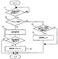
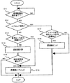
図19は、潤滑剤残量検知の制御フロー図である。
図19に示すように、制御部100は、潤滑剤塗布動作が終了したか否かをチェックする(S1)。塗布ローラ3aが、回転駆動する場合は、塗布ローラ3aを回転駆動する駆動モータがONからOFFに切り替わったことを検知することで、潤滑剤塗布動作が終了したことを検知することができる。塗布ローラ3aが、感光体1と連れ回りする場合は、例えば、感光体1を回転駆動させる駆動モータがONからOFFに切り替わったことを検知することで潤滑剤塗布動作が終了したことを検知することができる。また、これに限らず、エンコーダなどで塗布ローラ3aが停止したことを検知することで潤滑剤塗布動作が終了したことを検知してもよい。
FIG. 19 is a control flow diagram for detecting the remaining amount of lubricant.
As shown in FIG. 19, the control unit 100 checks whether or not the lubricant application operation is finished (S1). When the application roller 3a is rotationally driven, it can be detected that the lubricant application operation has been completed by detecting that the drive motor that rotationally drives the application roller 3a is switched from ON to OFF. When the application roller 3a rotates with the photoreceptor 1, for example, it is detected that the lubricant application operation has been completed by detecting that the drive motor that rotationally drives the photoreceptor 1 is switched from ON to OFF. be able to. Further, the present invention is not limited to this, and it may be detected that the lubricant application operation has ended by detecting that the application roller 3a has stopped using an encoder or the like.

制御部100は、潤滑剤塗布動作が終了し(S1のYES)、ニアエンド状態を検知していないとき(S2のNO)は、第1電極部材42aと第2電極部材42bとの間に電圧を印加し、抵抗検知部42cで抵抗値を測定する(S2)。抵抗検知部42cで測定した抵抗値が所定値以下の場合(S3のYES)は、潤滑剤がニアエンド状態であると判定し、その旨をユーザーに報知する(S4)。   When the lubricant application operation is finished (YES in S1) and the near-end state is not detected (NO in S2), the controller 100 applies a voltage between the first electrode member 42a and the second electrode member 42b. And the resistance value is measured by the resistance detector 42c (S2). When the resistance value measured by the resistance detection unit 42c is equal to or less than the predetermined value (YES in S3), it is determined that the lubricant is in the near-end state, and that is notified to the user (S4).

一方、ニアエンドを検知しているとき(S2のYES)は、ニアエンド後の塗布ローラ3aの走行距離が所定値Bt以上のとき(S6のYES)は、潤滑エンドと検知し(S7)、画像形成動作を禁止する。   On the other hand, when the near end is detected (YES in S2), when the travel distance of the application roller 3a after the near end is equal to or greater than the predetermined value Bt (YES in S6), the lubrication end is detected (S7), and image formation is performed. Prohibit operation.

このように、潤滑剤動作終了後の潤滑剤動作停止中に潤滑剤の残量検知を行うことで、潤滑剤保持部材3dが傾いていない状態で残量検知を行うことができ、正確な潤滑剤の残量検知を行うことができる。また、固形潤滑剤が振動していない状態で残量検知を行うことができる。よって、固形潤滑剤ニアエンド時において、第2電極部材42bが第1電極部材42aに安定的に接触した状態で検知することができる。その結果、正確に固形潤滑剤のニアエンドを検知することができる。また、潤滑剤保持部材と電極部材との間に高い電圧をかけずとも、良好に導通状態を検知することができ、消費電力も必要最低限でおさえることができる。なお、上述では、潤滑剤動作終了後に残量検知を行っているが、潤滑剤動作開始前に残量検知を行ってもよい。また、ニアエンド後に行うエンド検知を常に行うようにしてもよい。   Thus, by detecting the remaining amount of the lubricant while the lubricant operation is stopped after the end of the lubricant operation, the remaining amount can be detected in a state where the lubricant holding member 3d is not tilted, and accurate lubrication is performed. The remaining amount of the agent can be detected. Further, the remaining amount can be detected in a state where the solid lubricant is not vibrating. Therefore, at the time of the solid lubricant near-end, it is possible to detect the second electrode member 42b in a state where it is stably in contact with the first electrode member 42a. As a result, the near end of the solid lubricant can be accurately detected. In addition, the conductive state can be detected well without applying a high voltage between the lubricant holding member and the electrode member, and the power consumption can be suppressed to the minimum necessary. In the above description, the remaining amount is detected after the end of the lubricant operation, but the remaining amount may be detected before the start of the lubricant operation. Further, end detection performed after the near end may be always performed.

低画像面積率を頻繁に出力する使用条件の場合、収納ケース3e中央部にも感光体へ塗布されなかった粉体状の潤滑剤が収納ケース3eに堆積していく。よって、このような条件下では、収納ケースの中央部よりに開口部31eを設けた構成でも、開口部31eから多くの潤滑剤が飛散してしまう。その結果、仕切り壁43bの検知用回転部材41を通すための連通部を通って、カバー部材43の第1電極部材42a、第2電極部材42bが配置された空間に入り込む潤滑剤粉も多くなる。よって、第1電極部材42a,第2電極部材42bに付着する潤滑剤粉も多くなる。その結果、電極部材間で導通不良が生じ、潤滑剤のニアエンドを検知することができないおそれがある。そこで、塗布ローラ3aの走行距離および電極部材間の導通状態の両方で、潤滑剤のニアエンドを検知してもよい。   In the use condition in which the low image area ratio is frequently output, the powdery lubricant that has not been applied to the photosensitive member also accumulates in the storage case 3e in the central portion of the storage case 3e. Therefore, under such a condition, a large amount of lubricant is scattered from the opening 31e even in the configuration in which the opening 31e is provided from the central portion of the storage case. As a result, the amount of lubricant powder that enters the space in which the first electrode member 42a and the second electrode member 42b of the cover member 43 are disposed through the communication portion for passing the detection rotating member 41 of the partition wall 43b increases. . Therefore, the amount of lubricant powder adhering to the first electrode member 42a and the second electrode member 42b also increases. As a result, conduction failure occurs between the electrode members, and there is a possibility that the near end of the lubricant cannot be detected. Therefore, the near end of the lubricant may be detected by both the travel distance of the application roller 3a and the conductive state between the electrode members.

図20は、塗布ローラ3aの走行距離および残量検知部40の両方でニアエンドを行う場合の制御フロー図である。
図20に示すように、潤滑剤塗布動作終了後(S11のYES)、残量検知部40でニアエンドを検知してない(S12のNO)場合は、塗布ローラ3aの走行距離が、所定値B1以上か否かをチェックする(S13)。所定値B1以下(S13のNO)の場合は、抵抗検知部42cで抵抗値の測定を行い(S14)、抵抗値が所定値以下か否かをチェックする(S15)。抵抗値が所定値以下(S15のYES)の場合は、電極部材間42a,42bとが導通しているので、潤滑剤ニアエンドと判定(S16)し、ユーザーに報知する。また、塗布ローラ3aの走行距離が、所定値B1以上のとき(S3のYES)も、潤滑剤ニアエンドと判定(S6)し、ユーザーに報知する。
FIG. 20 is a control flow diagram in the case of performing near-end in both the travel distance of the application roller 3a and the remaining amount detection unit 40.
As shown in FIG. 20, after the lubricant application operation is completed (YES in S11), when the near end is not detected by the remaining amount detector 40 (NO in S12), the travel distance of the application roller 3a is a predetermined value B1. It is checked whether or not this is the case (S13). If the value is equal to or less than the predetermined value B1 (NO in S13), the resistance value is measured by the resistance detector 42c (S14), and it is checked whether the resistance value is equal to or less than the predetermined value (S15). When the resistance value is equal to or smaller than the predetermined value (YES in S15), the electrode members 42a and 42b are in conduction, so it is determined that the lubricant is near the end (S16), and the user is notified. Also, when the travel distance of the application roller 3a is equal to or greater than the predetermined value B1 (YES in S3), it is determined that the lubricant is near end (S6), and the user is notified.

図21は、固形潤滑剤量の推移とニアエンド検知のタイミングとを示す図である。
図21に示すように、通常の使用条件のときは、塗布ローラ3aが所定値B1となる前に、電極部材間が導通し、ニアエンドが検知される。一方、低画像面積率の画像を頻繁に出力するような使用条件のときは、電極部材間が導通する前に、塗布ローラ3aの走行距離が所定値B1となり、ニアエンドが検知される。そして、ニアエンドが検知されてから、塗布ローラ3aの走行距離が、上限値B1となったら、潤滑剤エンド状態として、画像形成動作を禁止する。
FIG. 21 is a diagram showing the transition of the amount of solid lubricant and the timing of near-end detection.
As shown in FIG. 21, under normal use conditions, the electrode members are brought into conduction and the near end is detected before the application roller 3a reaches the predetermined value B1. On the other hand, when the use condition is such that an image with a low image area ratio is frequently output, the travel distance of the application roller 3a becomes a predetermined value B1 before the electrode members are electrically connected, and the near end is detected. Then, after the near end is detected, when the travel distance of the application roller 3a reaches the upper limit value B1, the image forming operation is prohibited as the lubricant end state.

このように、ニアエンドを検知できない事態が生じるおそれがある低画像面積率の画像を頻繁に出力する使用条件のときは、塗布ローラ3aの走行距離でニアエンドを検知することができる。これにより、残量検知部40でニアエンドが検知されずに、そのまま使用され続けることを防止することができる。これにより、感光体表面を確実に潤滑剤で保護できる。   As described above, in the use condition in which an image with a low image area ratio that may cause a situation where the near end cannot be detected is frequently output, the near end can be detected based on the travel distance of the application roller 3a. As a result, it is possible to prevent the remaining amount detection unit 40 from being used as it is without being detected as a near end. Thereby, the surface of the photoreceptor can be reliably protected with the lubricant.

塗布ローラ3aの走行距離以外にも、塗布ローラ3aの回転時間等を計測することで、ニアエンドを検知してもよい。また、塗布ローラ3aが、回転駆動する構成で、環境変動等により潤滑剤塗布ローラの回転数を変化させる制御を搭載した場合は、走行距離を計測することが、より精度よくニアエンドを予測できる構成となる。   In addition to the travel distance of the application roller 3a, the near end may be detected by measuring the rotation time of the application roller 3a. In addition, when the application roller 3a is driven to rotate and is equipped with a control for changing the number of rotations of the lubricant application roller due to environmental fluctuations or the like, it is possible to predict the near end more accurately by measuring the travel distance. It becomes.

上記では、上限値B1として、低画像面積率の画像を頻繁に出力したときに固形潤滑剤がニアエンドとなる塗布ローラ3aの走行距離に設定したが、これに限られない。例えば、プロセスカートリッジ内の部品で、低画像面積率の画像を頻繁に出力したときに固形潤滑剤がニアエンドとなる前に、寿命が来る部品がある場合、その部品の寿命となる塗布ローラ3aの走行距離を上限値B1としてもよい。   In the above description, the upper limit value B1 is set to the travel distance of the application roller 3a in which the solid lubricant becomes near-end when images with a low image area ratio are frequently output, but is not limited thereto. For example, if there is a part that has reached the end of its life before the solid lubricant becomes near-end when a low image area ratio image is frequently output among the parts in the process cartridge, The travel distance may be the upper limit value B1.

また、図22に示すように、第1電極部材42aと第2電極部材42とを水平方向に対向配置させてもよい。このように、電極部材42aと第2電極部材42とを水平方向に対向配置することにより各電極部材の面が、水平方向に対して直交する方向となる。これにより、各電極部材の面に潤滑剤などが堆積することがなくなり、電極部材間に導通不良が生じるのを抑制することができ、精度よく潤滑剤のニアエンドを検知することができる。   Further, as shown in FIG. 22, the first electrode member 42a and the second electrode member 42 may be disposed to face each other in the horizontal direction. Thus, by arranging the electrode member 42a and the second electrode member 42 so as to face each other in the horizontal direction, the surface of each electrode member becomes a direction orthogonal to the horizontal direction. As a result, lubricant or the like is not deposited on the surface of each electrode member, it is possible to suppress poor conduction between the electrode members, and the near end of the lubricant can be detected with high accuracy.

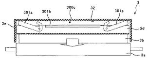
図23は、押し当て機構の変形例を示す概略構成図である。
この変形例の押し当て機構300cは、潤滑剤保持部材3dの長手方向両端部付近にそれぞれ設けられ、収納ケース3eに揺動自在に取り付けられた揺動部材301aと、付勢手段であるバネ301bとを有している。バネ301bの各端部がそれぞれ揺動部材301aに取り付けられている。各揺動部材301aは、このバネ301bから潤滑剤保持部材の長手方向中心に向かう図中矢印Dの向きの付勢力を得ている。この付勢力によって、図中右側の揺動部材は図中反時計回りに、図中左側の揺動部材は図中時計回りに揺動するように付勢される。これにより、各揺動部材301aの潤滑剤保持部材3dと当接する円弧状の当接部311は、図23に示すように潤滑剤保持部材3d側へ付勢される。
FIG. 23 is a schematic configuration diagram illustrating a modification of the pressing mechanism.
The pressing mechanism 300c of this modification is provided in the vicinity of both ends in the longitudinal direction of the lubricant holding member 3d, and a swinging member 301a that is swingably attached to the storage case 3e, and a spring 301b that is a biasing means. And have. Each end of the spring 301b is attached to the swing member 301a. Each oscillating member 301a obtains a biasing force in the direction of arrow D in the figure from the spring 301b toward the longitudinal center of the lubricant holding member. By this urging force, the swing member on the right side in the drawing is biased so as to swing counterclockwise in the drawing and the swing member on the left side in the drawing swings clockwise in the drawing. As a result, the arc-shaped contact portion 311 that contacts the lubricant holding member 3d of each swing member 301a is urged toward the lubricant holding member 3d as shown in FIG.

使用初期時においては、各揺動部材301aの揺動端部がバネ301bの付勢力に抗して収納ケース3eの上面部の内周面32へ近づく方向に揺動した状態となっている。このような構成により、2つの揺動部材301aはバネ301bの付勢力を受けて互いに均等な力で潤滑剤保持部材3dを押し、潤滑剤保持部材3dに保持された固形潤滑剤3bを塗布ローラ3aに押し当てる。よって、固形潤滑剤3bは、その長尺方向において塗布ローラ3aへ均一に押圧される。その結果、塗布ローラ3aの回転により摺擦されることで削り取られる潤滑剤の量は、長尺方向において均一となり、感光体1の表面に潤滑剤をムラなく塗布することができる。   In the initial stage of use, the swinging end portion of each swinging member 301a is swung in a direction approaching the inner peripheral surface 32 of the upper surface portion of the storage case 3e against the biasing force of the spring 301b. With such a configuration, the two swinging members 301a receive the urging force of the spring 301b, push the lubricant holding member 3d with equal force, and apply the solid lubricant 3b held by the lubricant holding member 3d to the application roller. Press against 3a. Therefore, the solid lubricant 3b is uniformly pressed against the application roller 3a in the longitudinal direction. As a result, the amount of the lubricant scraped off by the rotation of the application roller 3a is uniform in the longitudinal direction, and the lubricant can be applied evenly on the surface of the photoreceptor 1.

この変形例の押し当て機構300cにおいては、経時使用によって固形潤滑剤3bの高さが減っても固形潤滑剤3bの加圧力の減少を抑制できる。よって、初期から経時にかけて感光体1の表面に供給される粉末潤滑剤量の変動を小さく抑えることができる。   In the pressing mechanism 300c of this modified example, even if the height of the solid lubricant 3b is reduced by use over time, it is possible to suppress a decrease in the applied pressure of the solid lubricant 3b. Therefore, fluctuations in the amount of the powder lubricant supplied to the surface of the photoreceptor 1 from the initial stage over time can be suppressed to a small level.

このような結果が得られる理由は、次の通りである。
一般に、初期から固形潤滑剤3bが無くなるまでの間に変化するバネの伸び変化量に対し、バネ全体の長さを長くすれば長くするほど、バネの伸び変化量に対するバネの付勢力変動は小さくて済む。図2に示した押し当て機構としての加圧バネ3cを縮めた状態で配置し、その付勢力(押し出し力)の方向と塗布ローラ3aに対する固形潤滑剤3bの押し当て方向とを一致させている。この構成においては、バネ全体の長さを長くするほど、バネの付勢力方向と塗布ローラ3aに対する固形潤滑剤3bの押し当て方向とを一致させることが困難となることから、バネ全体の長さを長くするにも限界がある。加えて、図3の押し当て機構3cでは、塗布ローラ3aの径方向にバネの長さ分の配置スペースを確保しなければならず、装置の大型化につながる。これらの理由から、図2の押し当て機構においては、比較的短いバネを使用しなければならず、経時的なバネの付勢力変動が大きくなる。
The reason why such a result is obtained is as follows.
In general, as the length of the spring as a whole increases with respect to the amount of change in spring extension that changes from the beginning until the solid lubricant 3b disappears, the variation in the biasing force of the spring with respect to the amount of change in spring spring decreases. I'll do it. The pressure spring 3c as the pressing mechanism shown in FIG. 2 is disposed in a contracted state, and the direction of the urging force (extrusion force) is matched with the pressing direction of the solid lubricant 3b against the application roller 3a. . In this configuration, the longer the length of the entire spring, the more difficult it is to match the direction of the urging force of the spring and the direction of pressing the solid lubricant 3b against the application roller 3a. There is a limit to how long it can be. In addition, in the pressing mechanism 3c of FIG. 3, it is necessary to secure an arrangement space for the length of the spring in the radial direction of the application roller 3a, leading to an increase in the size of the apparatus. For these reasons, the pressing mechanism of FIG. 2 must use a relatively short spring, and the urging force fluctuation of the spring over time increases.

これに対し、この変形例の押し当て機構300cにおいては、図23に示したように、バネ301bを伸ばした状態で配置し、その付勢力(引っ張り力)で塗布ローラ3aに対して固形潤滑剤3b押し当てることができる。よって、バネ全体の長さを長くしても図2の押し当て機構3cのような問題は生じない。しかも、変形例の押し当て機構300cでは、バネ301bの長さ方向が固形潤滑剤3bの長尺方向すなわち塗布ローラ3aの軸方向に一致するようにバネ301bが配置される。したがって、バネ301bの長さを長くしても、塗布ローラ3aの径方向に配置スペースが広がることはなく、装置を大型化する必要がない。そのため、この変形例の押し当て機構300cは、図2に示した押し当て機構3cで使用していた加圧バネ3cの長さよりもずっと長いバネ301bを採用できる。その結果、経時的なバネの付勢力変動を小さく抑えることができる。   On the other hand, in the pressing mechanism 300c of this modified example, as shown in FIG. 23, the spring 301b is arranged in an extended state, and the solid lubricant is applied to the application roller 3a by its urging force (tensile force). 3b can be pressed. Therefore, even if the length of the entire spring is increased, the problem as in the pressing mechanism 3c in FIG. 2 does not occur. Moreover, in the pressing mechanism 300c of the modified example, the spring 301b is arranged so that the length direction of the spring 301b coincides with the long direction of the solid lubricant 3b, that is, the axial direction of the application roller 3a. Therefore, even if the length of the spring 301b is increased, the arrangement space does not increase in the radial direction of the application roller 3a, and the apparatus does not need to be enlarged. Therefore, the pressing mechanism 300c of this modification can employ a spring 301b that is much longer than the length of the pressure spring 3c used in the pressing mechanism 3c shown in FIG. As a result, it is possible to suppress fluctuations in the biasing force of the spring over time.

また、図24に示すように、潤滑剤保持部材3dに各揺動部材301aを揺動自在に取り付けてもよい。この図24の構成においては、各揺動部材301aは、バネ301bから潤滑剤保持部材3dの長手方向中心に向かう付勢力によって、各揺動部材301aの揺動端部が、潤滑剤保持部材3dから離れる方向に付勢され、各揺動部材301aの揺動端部が、収納ケース3eの上面部の内周面32に当接する構成となる。   Further, as shown in FIG. 24, each swinging member 301a may be swingably attached to the lubricant holding member 3d. In the configuration of FIG. 24, each swinging member 301a has its swinging end portion of each swinging member 301a moved to the center of the lubricant holding member 3d in the longitudinal direction by the spring 301b. The swing end portion of each swing member 301a is in contact with the inner peripheral surface 32 of the upper surface portion of the storage case 3e.

また、図25に示すように、第2電極部材42bが、潤滑剤保持部材3dの押し当て部31dに直接、当接する構成としてもよい。この場合、第2電極部材42bが、第1電極部材42aよりも鉛直上方に位置し、第2電極部材42bの自由端に設けられた突出部47との当接面である第1電極部材42aの上面に潤滑剤などが堆積する。しかし、上述したように、突出部47で容易に潤滑剤を押し退けることができるので、第1電極部材42aの上面の堆積した潤滑剤などの堆積物Tを突出部47により押し退けて、突出部47を第2電極部材42bに当接させることができる。   Further, as shown in FIG. 25, the second electrode member 42b may be in direct contact with the pressing portion 31d of the lubricant holding member 3d. In this case, the second electrode member 42b is positioned vertically above the first electrode member 42a, and is a first electrode member 42a that is a contact surface with the protruding portion 47 provided at the free end of the second electrode member 42b. A lubricant etc. is deposited on the upper surface of the substrate. However, as described above, since the lubricant can be easily pushed away by the protrusion 47, the deposit T such as lubricant deposited on the upper surface of the first electrode member 42a is pushed away by the protrusion 47, and the protrusion 47 Can be brought into contact with the second electrode member 42b.

また、中間転写ベルト56に潤滑剤を塗布する潤滑剤供給装置に、上述した潤滑剤供給装置を適用してもよい。   Further, the above-described lubricant supply device may be applied to the lubricant supply device that applies the lubricant to the intermediate transfer belt 56.

以上に説明したものは一例であり、本発明は、次の(1)〜(18)態様毎に特有の効果を奏する。
(1)
固形潤滑剤3bと、固形潤滑剤3bに当接し、これを摺擦することで削り取った潤滑剤を感光体1などの潤滑剤供給対象に供給する塗布ローラ3aなどの供給部材と、第1電極部材42a、上記第1電極部材42aに対向配置され上記固形潤滑剤3bの供給部材による削り取りながらの移動に伴い上記第1電極部材側へ移動し、上記固形潤滑剤の残量が上記所定量となると、上記第1電極部材42aに当接する第2電極部材42b、および、上記第1電極部材42aと上記第2電極部材42bとの間に電圧を印加して導通を検知する抵抗検知部42cなどの導通検知手段を備え、導通検知手段により上記第1電極部材42aと上記第2電極部材42bとの間の導通を検知することで上記固形潤滑剤3bの残量が所定量以下であることを検知する残量検知部40などの残量検知手段と、を備えた潤滑剤供給装置3において、上記第1電極部材42aまたは上記第2電極部材42bの、上記固形潤滑剤3bの残量が上記所定量のときに対向する電極部材に当接する当接部を、対向する電極部材側に突出させた。
かかる構成を備えることで、実施形態で説明したように、面同士を当接させる場合に比べて、当接圧を高めることができ、かつ、当接する範囲を狭めることができる。これにより、第2電極部材42bが第1電極部材42aに当接する際に電極部材に付着した付着物を押し退けることができ、電極部材間に付着物が挟まるのを抑制することができる。よって、固形潤滑剤の潤滑剤量が所定以下となると、良好に導通し、良好に潤滑剤の残量を検知することができる。
What was demonstrated above is an example, and this invention has an effect peculiar for every following (1)-(18) aspect.
(1)
A solid lubricant 3b, a supply member such as an application roller 3a for supplying the lubricant, which comes into contact with the solid lubricant 3b and is scraped by rubbing the solid lubricant 3b, to a lubricant supply target such as the photoreceptor 1, and the first electrode The member 42a is disposed to face the first electrode member 42a and moves toward the first electrode member as the solid lubricant 3b is being scraped by the supply member, and the remaining amount of the solid lubricant is equal to the predetermined amount. Then, a second electrode member 42b that contacts the first electrode member 42a, a resistance detector 42c that detects conduction by applying a voltage between the first electrode member 42a and the second electrode member 42b, and the like. That the remaining amount of the solid lubricant 3b is less than or equal to a predetermined amount by detecting the continuity between the first electrode member 42a and the second electrode member 42b. Detect In the lubricant supply device 3 including a remaining amount detecting unit such as a remaining amount detecting unit 40, the remaining amount of the solid lubricant 3b of the first electrode member 42a or the second electrode member 42b is the predetermined amount. At this time, the abutting portion that abuts against the opposing electrode member was protruded toward the opposing electrode member.
By providing such a configuration, as described in the embodiment, the contact pressure can be increased and the contact range can be narrowed compared to the case where the surfaces are brought into contact with each other. Thereby, when the 2nd electrode member 42b contact | abuts to the 1st electrode member 42a, the deposit | attachment adhering to the electrode member can be pushed away, and it can suppress that an deposit | attachment pinches between electrode members. Therefore, when the amount of the lubricant in the solid lubricant is equal to or less than the predetermined value, the conduction is good and the remaining amount of the lubricant can be detected well.

(2)
また、上記(1)に記載の態様の潤滑剤供給装置3において、上記突出部47を複数設けた。
かかる構成を備えることで、実施形態で説明したように、ある突出部47が何らかの要因で第1電極部材42aと接触不良が生じたとしても、その他の突出部47のいずれかが、第1電極部材42aと良好に接触することができる。これにより、第1電極部材42aに確実に第2電極部材42bを当接させることができる。
(2)
Further, in the lubricant supply device 3 according to the aspect described in (1) above, a plurality of the protrusions 47 are provided.
With such a configuration, as described in the embodiment, even if a certain projecting portion 47 has a poor contact with the first electrode member 42a for some reason, any one of the other projecting portions 47 is not connected to the first electrode. It is possible to make good contact with the member 42a. Thereby, the 2nd electrode member 42b can be reliably made to contact | abut to the 1st electrode member 42a.

(3)
また、上記(1)または(2)に記載の態様の潤滑剤供給装置3において、上記突出部47の先端を、上記対向する電極部材と点接触または線接触する形状にした。
かかる構成とすることで、実施形態で説明したように、当接圧を高めることができ、突出部47で良好に電極部材に付着した付着物を押し退けることができる。これにより、より確実に第1電極部材42aに第2電極部材42bを当接させることができる。
(3)
In the lubricant supply device 3 according to the aspect described in (1) or (2) above, the tip of the protruding portion 47 has a shape that makes point contact or line contact with the opposing electrode member.
With such a configuration, as described in the embodiment, the contact pressure can be increased, and the deposit 47 can be pushed away favorably by the protrusion 47. Thereby, the 2nd electrode member 42b can be made to contact | abut more reliably to the 1st electrode member 42a.

(4)
また、上記(1)乃至(3)いずれかに記載の態様の潤滑剤供給装置3において、上記第2電極部材42bは、上記潤滑剤保持部材3dに直接または間接的に押されると、一端を支点にして撓み変形するものであって、上記突出部47を上記第2電極部材42bの他端部に設けた。
かかる構成を備えることで、実施形態で説明したように、第1電極部材42aに当接する際に、突出部47は、僅かではあるが、第1電極部材42aの面と平行な方向にも移動する。これにより、第1電極部材42aの面についた付着物を掻き落とす効果も期待できる。
(4)
Further, in the lubricant supply device 3 according to any one of the above (1) to (3), when the second electrode member 42b is pressed directly or indirectly by the lubricant holding member 3d, one end is pushed. The projecting portion 47 is provided at the other end of the second electrode member 42b.
By providing such a configuration, as described in the embodiment, when contacting the first electrode member 42a, the protruding portion 47 moves slightly in a direction parallel to the surface of the first electrode member 42a. To do. Thereby, the effect of scraping off the deposits on the surface of the first electrode member 42a can also be expected.

(5)
また、上記(1)乃至(4)いずれかに記載の態様の潤滑剤供給装置3において、上記第2電極部材42bが、上記第1電極部材42aに対して鉛直方向に対向配置されており、鉛直方向上方側の電極部材における対向する電極部材との当接部近傍の水平投影面積を、鉛直方向下方側の電極部材における対向する電極部材との当接部近傍の水平投影面積よりも大きくした。
かかる構成を備えることで、実施形態で説明したように、鉛直上方の電極部材が庇のような働きをし、鉛直上方から落下してきた潤滑剤をこの電極部材の上面部で受けることができる。これにより、鉛直下方の電極部材の上面部に潤滑剤が付着するのを抑制することができる。
(5)
Moreover, in the lubricant supply device 3 according to any one of the above (1) to (4), the second electrode member 42b is disposed to face the first electrode member 42a in the vertical direction, The horizontal projection area in the vicinity of the contact portion of the electrode member on the upper side in the vertical direction with the facing electrode member is made larger than the horizontal projection area in the vicinity of the contact portion of the electrode member on the lower side in the vertical direction with the facing electrode member. .
By providing such a configuration, as described in the embodiment, the vertically upper electrode member functions like a ridge, and the lubricant falling from vertically above can be received by the upper surface portion of the electrode member. Thereby, it can suppress that a lubricant adheres to the upper surface part of the electrode member of the perpendicular lower part.

(6)
また、上記(1)乃至(5)いずれかに記載の態様の潤滑剤供給装置3において、上記第2電極部材42bと上記第1電極部材42aとを水平方向に対向配置した。
かかる構成を備えることで、図22を用いて説明したように、各電極部材の面に潤滑剤などが堆積することがなくなり、電極部材間に導通不良が生じるのを抑制することができ、精度よく潤滑剤のニアエンドを検知することができる。
(6)
In the lubricant supply device 3 according to any one of (1) to (5), the second electrode member 42b and the first electrode member 42a are disposed to face each other in the horizontal direction.
By providing such a configuration, as described with reference to FIG. 22, no lubricant or the like is deposited on the surface of each electrode member, and it is possible to suppress poor conduction between the electrode members. The near end of the lubricant can be detected well.

(7)
また、上記(1)乃至(6)いずれかに記載の態様の潤滑剤供給装置3において、上記第2電極部材42bが上記第1電極部材側へ移動しているときに、上記第2電極部材42bの上記第1電極部材42aとの当接部と摺擦して付着物を除去する清掃ブラシ48などの清掃部材を設けた。
かかる構成を備えることで、図16を用いて説明したように、第1電極部材42aに確実に第2電極部材42bを当接させることができ、精度よくニアエンドを検知することができる。
(7)
In the lubricant supply device 3 according to any one of the above (1) to (6), the second electrode member is moved when the second electrode member 42b is moving toward the first electrode member. A cleaning member such as a cleaning brush 48 is provided that removes deposits by rubbing against the contact portion of 42b with the first electrode member 42a.
With this configuration, as described with reference to FIG. 16, the second electrode member 42b can be reliably brought into contact with the first electrode member 42a, and the near end can be detected with high accuracy.

(8)
また、上記(7)に記載の態様の潤滑剤供給装置3において、上記第2電極部材42bと上記第1電極部材42aとを水平方向に対向配置しており、上記第2電極部材42bを、上記第1電極部材42aよりも鉛直下側に設けた。
かかる構成を備えることで、図16を用いて説明したように、清掃部材で掻き落とした付着物が、第1電極部材に再付着するのを防止することができる。
(8)
Further, in the lubricant supply device 3 according to the aspect described in (7), the second electrode member 42b and the first electrode member 42a are disposed to face each other in the horizontal direction, and the second electrode member 42b is The first electrode member 42a is provided vertically below the first electrode member 42a.
By providing such a configuration, as described with reference to FIG. 16, it is possible to prevent the deposits scraped off by the cleaning member from reattaching to the first electrode member.

(9)
また、上記(1)乃至(8)いずれかの潤滑剤供給装置3において、上記突出部47の周囲を囲って上記突出部47を遮蔽する遮蔽部材49を設けた。
かかる構成を備えることで、図17、図18を用いて説明したように、突出部47に潤滑剤などが付着するのを抑制することができる。
(9)
In the lubricant supply device 3 according to any one of (1) to (8), a shielding member 49 that surrounds the protrusion 47 and shields the protrusion 47 is provided.
By providing such a configuration, it is possible to prevent the lubricant or the like from adhering to the protrusion 47 as described with reference to FIGS.

(10)
また、上記(9)に記載の態様の潤滑剤供給装置3において、上記遮蔽部材を絶縁性の変形し易い材質で構成し、上記遮蔽部材49を上記突出部よりも対向する電極部材側に延ばして、上記突出部が当接する電極部材の上記突出部当接部周辺も覆った。
かかる構成を備えることで、図17、図18を用いて説明したように、対向する電極部材の突出部47が当接する箇所にも潤滑剤などが付着するのを抑制することができる。また、遮蔽部材は絶縁性であるので、突出部よりも先に遮蔽部材49が対向する電極部材に当接しても、電極部材間で導通することはない。また、遮蔽部材49を変形し易い材質で構成することで、第2電極部材が第1電極部材側へ移動して、遮蔽部材49が圧縮変形せしめられたときに、遮蔽部材49の復元力により第2電極部材や第1電極部材が変形するのを抑制することができる。
(10)
In the lubricant supply device 3 according to the aspect described in (9) above, the shielding member is made of an insulating and easily deformable material, and the shielding member 49 is extended to the electrode member side facing the protruding portion. Thus, the periphery of the projecting portion abutting portion of the electrode member with which the projecting portion abuts is also covered.
By providing such a configuration, as described with reference to FIGS. 17 and 18, it is possible to prevent the lubricant or the like from adhering to a place where the protruding portion 47 of the opposing electrode member contacts. Further, since the shielding member is insulative, even if the shielding member 49 comes into contact with the opposing electrode member before the protruding portion, there is no conduction between the electrode members. Further, by configuring the shielding member 49 with a material that is easily deformed, when the second electrode member moves toward the first electrode member and the shielding member 49 is compressed and deformed, the restoring force of the shielding member 49 Deformation of the second electrode member or the first electrode member can be suppressed.

(11)
また、上記(1)乃至(10)いずれかに記載の態様の潤滑剤供給装置3において、上記固形潤滑剤3bを収納する収納ケース3eを備え、残量検知部40などの残量検知手段を収納ケース3eの外に設けた。
かかる構成を備えることで、実施形態で説明したように、第2電極部材42bや第1電極部材42aに潤滑剤が付着するのを抑制することができる。
(11)
The lubricant supply device 3 according to any one of the above (1) to (10) includes a storage case 3e for storing the solid lubricant 3b, and a remaining amount detection unit such as a remaining amount detection unit 40. It was provided outside the storage case 3e.
By providing such a configuration, it is possible to suppress the lubricant from adhering to the second electrode member 42b and the first electrode member 42a as described in the embodiment.

(12)
また、上記(11)に記載の潤滑剤供給装置3において、上記収納ケース3eには、上記潤滑剤保持部材3dの第2電極部材42bを直接または間接的に押し込む押し当て部31dが貫通する開口部31eが設けられており、残量検知部40などの残量検知手段と上記開口部31eとを覆うカバー部材43を設けた。
かかる構成を備えることで、実施形態で説明したように、開口部31eから飛散した潤滑剤で装置が汚れるのを防止することができる。また、第1電極部材42aや第2電極部材42bに飛散トナーが付着するのを防止することができる。
(12)
Further, in the lubricant supply device 3 described in (11) above, an opening through which the pressing portion 31d for directly or indirectly pressing the second electrode member 42b of the lubricant holding member 3d penetrates the storage case 3e. A portion 31e is provided, and a cover member 43 that covers the remaining amount detecting means such as the remaining amount detecting unit 40 and the opening 31e is provided.
By providing such a configuration, as described in the embodiment, the apparatus can be prevented from being contaminated by the lubricant scattered from the opening 31e. Further, scattered toner can be prevented from adhering to the first electrode member 42a and the second electrode member 42b.

(13)
また、上記(12)に記載の態様の潤滑剤供給装置3において、上記カバー部材43に残量検知部40などの残量検知手段を保持した。
かかる構成を備えることで、実施形態で説明したように、残量検知部40などの残量検知手段の交換を容易に行うことができる。
(13)
Further, in the lubricant supply device 3 according to the aspect described in (12) above, the cover member 43 holds the remaining amount detecting means such as the remaining amount detecting unit 40.
By providing such a configuration, as described in the embodiment, replacement of the remaining amount detecting means such as the remaining amount detecting unit 40 can be easily performed.

(14)
また、上記(1)乃至(13)いずれかに記載の態様の潤滑剤供給装置3において、上記潤滑剤保持部材3dに押されて回転し、上記第2電極部材42bを上記第1電極部材側へ押し込む検知用回転部材41を設けた。
かかる構成を備えることで、実施形態で説明したように、第1電極部材42a、第2電極部材42bを、開口部31eから離れた位置に配置することができる。これにより、第1電極部材42a、第2電極部材42bに潤滑剤が付着するのを抑制することができる。
(14)
Further, in the lubricant supply device 3 according to any one of the above (1) to (13), the lubricant holding member 3d is pushed to rotate, and the second electrode member 42b is moved to the first electrode member side. A rotation member 41 for detection to be pushed in is provided.
By providing such a configuration, as described in the embodiment, the first electrode member 42a and the second electrode member 42b can be arranged at positions away from the opening 31e. Thereby, it can suppress that a lubricant adheres to the 1st electrode member 42a and the 2nd electrode member 42b.

(15)
また、上記(14)に記載の態様の潤滑剤供給装置3において、上記残量検知部40などの残量検知手段が上記固形潤滑剤3bを収納する収納ケース3eの外に設けられており、上記収納ケース3eに、上記潤滑剤保持部材3dの第2電極部材42bを直接または間接的に押し込む押し当て部31dが貫通する開口部31eが設けられた構成であって、上記残量検知手段と上記開口部31eとを仕切る仕切り壁43bを設けた。
かかる構成を備えることで、実施形態で説明したように、開口部31eからカバー部材43内へ進入した潤滑剤粉が、第1電極部材42a、第2電極部材42bに付着するのを抑制することができる。
(15)
In the lubricant supply device 3 according to the aspect described in (14) above, the remaining amount detecting means such as the remaining amount detecting unit 40 is provided outside the storage case 3e that stores the solid lubricant 3b, The storage case 3e is provided with an opening 31e through which a pressing portion 31d for directly or indirectly pressing the second electrode member 42b of the lubricant holding member 3d is provided, and the remaining amount detecting means A partition wall 43b that partitions the opening 31e was provided.
With this configuration, as described in the embodiment, the lubricant powder that has entered the cover member 43 from the opening 31e is prevented from adhering to the first electrode member 42a and the second electrode member 42b. Can do.

(16)
また、上記(1)乃至(15)いずれかに記載の態様の潤滑剤供給装置3において、残量検知部40などの残量検知手段を、上記固形潤滑剤長手方向に複数設けた。
かかる構成を備えることで、実施形態で説明したように、固形潤滑剤3bが長手方向で潤滑剤の消費量が異なった場合でも、消費量が多い方の側の端部の潤滑剤量がニアエンドとなった状態を検知することができる。これにより、固形潤滑剤の一方側端部の潤滑剤が枯渇して、感光体表面を傷つけてしまうなどの不具合が発生するのを防止することができる。
(16)
In the lubricant supply device 3 according to any one of the above (1) to (15), a plurality of remaining amount detection means such as the remaining amount detection unit 40 are provided in the solid lubricant longitudinal direction.
By providing such a configuration, as described in the embodiment, even when the solid lubricant 3b has a different amount of lubricant in the longitudinal direction, the amount of lubricant at the end on the side where the amount of consumption is larger is near-end. It is possible to detect the state of becoming. As a result, it is possible to prevent the occurrence of problems such as exhaustion of the lubricant at one end of the solid lubricant and damage to the photoreceptor surface.

(17)
また、感光体1などの像担持体と、像担持体の表面に潤滑剤を供給する潤滑剤供給手段とを有し、像担持体上の画像を最終的に記録材上に転移させて該記録材上に画像を形成する画像形成装置において、潤滑剤供給手段として、上記(1)乃至(16)いずれかに記載の態様の潤滑剤供給装置を用いた。
かかる構成を備えることで、潤滑剤のニアエンドを良好に検知することができ、潤滑剤が枯渇した状態で画像形成動作が行われるのを抑制することができる。これにより、感光体の劣化を経時に亘り抑制することができる。
(17)
In addition, the image bearing member such as the photosensitive member 1 and a lubricant supplying unit that supplies a lubricant to the surface of the image bearing member are provided, and the image on the image bearing member is finally transferred onto a recording material to In the image forming apparatus for forming an image on the recording material, the lubricant supply device according to any one of the above (1) to (16) is used as the lubricant supply means.
With this configuration, the near end of the lubricant can be detected well, and the image forming operation can be suppressed from being performed when the lubricant is exhausted. Thereby, deterioration of the photoreceptor can be suppressed over time.

(18)
また、感光体1などの像担持体と、像担持体の表面に潤滑剤を供給する潤滑剤供給手段とを有し、画像形成装置本体に対して着脱可能に構成されたプロセスカートリッジにおいて、潤滑剤供給手段として、上記(1)乃至(16)いずれかに記載の態様の潤滑剤供給装置を用いた。
かかる構成を備えることで、潤滑剤のニアエンドを良好に検知することができ、潤滑剤が枯渇した状態で画像形成動作が行われるのを抑制することができる。これにより、感光体の劣化を経時に亘り抑制することができるプロセスカートリッジを提供することができる。
(18)
Further, in a process cartridge having an image carrier such as the photosensitive member 1 and a lubricant supply means for supplying a lubricant to the surface of the image carrier and configured to be detachable from the image forming apparatus main body, lubrication As the agent supply means, the lubricant supply device according to any one of the above (1) to (16) was used.
With this configuration, the near end of the lubricant can be detected well, and the image forming operation can be suppressed from being performed when the lubricant is exhausted. Thereby, it is possible to provide a process cartridge capable of suppressing deterioration of the photoreceptor over time.

1:感光体
3:潤滑剤供給装置
3a:塗布ローラ
3b:固形潤滑剤
3c:押し当て機構
3d:潤滑剤保持部材
3e:収納ケース
31d:押し当て部
31e:開口部
40:残量検知部
41:検知用回転部材
42:回転検知部
42a:第1電極部材
42b:第2電極部材
42c:抵抗検知部
43:カバー部材
43b:仕切り壁
43c:回転軸
44a第1端子
44b:第2端子
43f1:第1ボス部
43f2:第2ボス部
47:突出部
48:清掃ブラシ
49:遮蔽部材
49a:貫通穴
1: Photoconductor 3: Lubricant supply device 3a: Application roller 3b: Solid lubricant 3c: Pushing mechanism 3d: Lubricant holding member 3e: Storage case 31d: Pushing portion 31e: Opening 40: Remaining amount detecting portion 41 : Rotating member for detection 42: rotation detecting unit 42a: first electrode member 42b: second electrode member 42c: resistance detecting unit 43: cover member 43b: partition wall 43c: rotating shaft 44a first terminal 44b: second terminal 43f1: 1st boss | hub part 43f2: 2nd boss | hub part 47: Protrusion part 48: Cleaning brush 49: Shielding member 49a: Through-hole

特開平8−314346号公報JP-A-8-314346

Claims (18)

潤滑剤と、
上記潤滑剤を潤滑剤供給対象に供給する供給部材と、
第1電極部材と第2電極部材との導通状態を検知する導通検知手段と、を備え、
上記第1電極部材と上記第2電極部材との導通状態により、上記潤滑剤の残量が所定量以下であることが判定される潤滑剤供給装置において、
上記第2電極部材は、上記潤滑剤の消費に伴い移動する移動部材に直接または間接的に押されると、一端を支点にして撓み変形するものであって、
上記第2電極部材に、上記第1電極部材側に突出し、上記第1電極部材に当接する突出部を設けたことを特徴とする潤滑剤供給装置。
A lubricant,
A supply member for supplying the lubricant to a lubricant supply target;
A conduction detecting means for detecting a conduction state between the first electrode member and the second electrode member,
In the lubricant supply device in which it is determined that the remaining amount of the lubricant is equal to or less than a predetermined amount based on a conduction state between the first electrode member and the second electrode member.
When the second electrode member is pressed directly or indirectly by a moving member that moves with consumption of the lubricant, the second electrode member is bent and deformed with one end as a fulcrum,
A lubricant supply device, wherein the second electrode member is provided with a protruding portion that protrudes toward the first electrode member and contacts the first electrode member.
潤滑剤と、
上記潤滑剤を潤滑剤供給対象に供給する供給部材と、
第1電極部材と第2電極部材との導通状態を検知する導通検知手段と、を備え、
上記第1電極部材と上記第2電極部材との導通状態により、上記潤滑剤の残量が所定量以下であることが判定される潤滑剤供給装置において、
上記第1電極部材または上記第2電極部材に、他方の電極部材側に突出し、上記他方の電極部材に当接する突出部を設け、
上記第2電極部材が、上記第1電極部材に対して鉛直方向に対向配置されており、
鉛直方向上方側の電極部材における対向する電極部材との当接部近傍の水平投影面積を、鉛直方向下方側の電極部材における対向する電極部材との当接部近傍の水平投影面積よりも大きくしたことを特徴とする潤滑剤供給装置。
A lubricant,
A supply member for supplying the lubricant to a lubricant supply target;
A conduction detecting means for detecting a conduction state between the first electrode member and the second electrode member,
In the lubricant supply device in which it is determined that the remaining amount of the lubricant is equal to or less than a predetermined amount based on a conduction state between the first electrode member and the second electrode member.
The first electrode member or the second electrode member is provided with a protruding portion that protrudes toward the other electrode member and contacts the other electrode member,
The second electrode member is disposed vertically opposite the first electrode member;
The horizontal projection area in the vicinity of the contact portion of the electrode member on the upper side in the vertical direction with the facing electrode member is made larger than the horizontal projection area in the vicinity of the contact portion of the electrode member on the lower side in the vertical direction with the facing electrode member. A lubricant supply device.
請求項1に記載の潤滑剤供給装置において、
上記第1電極部材と上記第2電極部材とが対面していることを特徴とする潤滑剤供給装置。
The lubricant supply device according to claim 1,
The lubricant supply device, wherein the first electrode member and the second electrode member face each other.
請求項1または3に記載の潤滑剤供給装置において、
上記移動部材は、潤滑剤を保持する潤滑剤保持部材であることを特徴とする潤滑剤供給装置。
In the lubricant supply device according to claim 1 or 3,
The lubricant supply device, wherein the moving member is a lubricant holding member that holds a lubricant.
請求項1乃至4いずれかに記載の潤滑剤供給装置において、
上記突出部を複数設けたことを特徴とする潤滑剤供給装置。
The lubricant supply device according to any one of claims 1 to 4,
A lubricant supply device comprising a plurality of the protrusions.
請求項1乃至5いずれかに記載の潤滑剤供給装置において、
上記突出部の先端を、上記突出部が当接する方の電極部材と点接触または線接触する形状にしたことを特徴とする潤滑剤供給装置。
The lubricant supply device according to any one of claims 1 to 5,
The lubricant supplying device according to claim 1, wherein the tip of the protruding portion has a shape that makes point contact or line contact with the electrode member with which the protruding portion abuts .
請求項1、3、4、請求項2に記載の態様を除く請求項5または6に記載の潤滑剤供給装置において、
上記第2電極部材と上記第1電極部材とを水平方向に対向配置したことを特徴とする潤滑剤供給装置。
In the lubricant supply device according to claim 5 or 6, excluding the aspect according to claim 1, 3, 4, and 2.
The lubricant supply device, wherein the second electrode member and the first electrode member are disposed to face each other in the horizontal direction.
請求項1乃至7いずれかに記載の潤滑剤供給装置において、
上記第2電極部材が上記第1電極部材側へ移動しているときに、上記第2電極部材の上記第1電極部材との当接部と摺擦して付着物を除去する清掃部材を設けたことを特徴とする潤滑剤供給装置。
The lubricant supply device according to any one of claims 1 to 7,
A cleaning member is provided that removes deposits by rubbing against a contact portion of the second electrode member with the first electrode member when the second electrode member is moving toward the first electrode member. A lubricant supply device characterized by the above.
請求項7に記載の態様を除く請求項8に記載の潤滑剤供給装置において、
上記第2電極部材と上記第1電極部材とが鉛直方向に対向配置しており、
上記第2電極部材を、上記第1電極部材よりも鉛直下側に設けたことを特徴とする潤滑剤供給装置。
In the lubricant supply device according to claim 8, excluding the aspect according to claim 7,
The second electrode member and the first electrode member are arranged to face each other in the vertical direction,
The lubricant supply device, wherein the second electrode member is provided vertically below the first electrode member.
請求項1乃至9いずれかに記載の潤滑剤供給装置において、
上記突出部の周囲を囲って上記突出部を遮蔽する遮蔽部材を設けたことを特徴とする潤滑剤供給装置。
The lubricant supply device according to any one of claims 1 to 9,
A lubricant supply device comprising a shielding member that surrounds the projection and shields the projection.
請求項10に記載の潤滑剤供給装置において、
上記遮蔽部材を絶縁性の変形し易い材質で構成し、
上記遮蔽部材を上記突出部よりも対向する電極部材側に延ばして、上記突出部が当接する電極部材の上記突出部周辺も覆ったことを特徴とする潤滑剤供給装置。
The lubricant supply device according to claim 10, wherein
The shielding member is made of an insulating and easily deformable material,
The shielding member is extended on the electrode member side facing than the protruding portion, a lubricant supply device, characterized in that the protruding portion is also covered the protrusion circumferential sides of the abutting electrode member.
請求項1乃至11いずれかに記載の潤滑剤供給装置において、
上記潤滑剤を収納する収納ケースを備え、
上記導通検知手段を収納ケースの外に設けたことを特徴とする潤滑剤供給装置。
The lubricant supply device according to any one of claims 1 to 11,
A storage case for storing the lubricant;
A lubricant supply device, wherein the continuity detecting means is provided outside a storage case.
請求項12に記載の潤滑剤供給装置において、
上記収納ケースには、上記潤滑剤の消費に伴い移動して第2電極部材を直接または間接的に押す押し部材が貫通する開口部が設けられており、
上記導通検知手段と上記開口部とを覆うカバー部材を設けたことを特徴とする潤滑剤供給装置。
The lubricant supply device according to claim 12,
The storage case is provided with an opening through which a push member that moves with the consumption of the lubricant and pushes the second electrode member directly or indirectly passes,
A lubricant supply device comprising a cover member that covers the conduction detecting means and the opening.
請求項13に記載の潤滑剤供給装置において、
上記カバー部材に上記第1電極部材および上記第2電極部材を保持したことを特徴とする潤滑剤供給装置。
The lubricant supply device according to claim 13, wherein
The lubricant supply device, wherein the cover member holds the first electrode member and the second electrode member.
請求項1乃至14いずれかに記載の潤滑剤供給装置において、
上記潤滑剤の消費に伴い移動する押し部材に押されて回転し、上記第2電極部材を上記第1電極部材側へ押し込む回転部材を設けたことを特徴とする潤滑剤供給装置。
The lubricant supply device according to any one of claims 1 to 14,
A lubricant supply device, comprising: a rotating member that is pushed and rotated by a pushing member that moves as the lubricant is consumed, and that pushes the second electrode member toward the first electrode member.
請求項1乃至15いずれかに記載の潤滑剤供給装置において、
上記導通検知手段は、上記第1電極部材と上記第2電極部材との導通状態を検知する抵抗検知部を備え、
上記抵抗検知部が検知した電気抵抗値が所定値以下であることが検知されることにより、上記潤滑剤の残量が所定量以下であることが判定されることを特徴とする潤滑剤供給装置。
The lubricant supply device according to any one of claims 1 to 15,
The conduction detection means includes a resistance detection unit that detects a conduction state between the first electrode member and the second electrode member,
Lubricant supply device characterized in that it is determined that the remaining amount of lubricant is not more than a predetermined amount by detecting that the electrical resistance value detected by the resistance detection unit is not more than a predetermined value. .
像担持体と、該像担持体の表面に潤滑剤を供給する潤滑剤供給手段とを有し、該像担持体上の画像を最終的に記録材上に転移させて該記録材上に画像を形成する画像形成装置において、
上記潤滑剤供給手段として、請求項1乃至16いずれかに記載の潤滑剤供給装置を用いたことを特徴とする画像形成装置。
An image carrier, and a lubricant supply means for supplying a lubricant to the surface of the image carrier, and finally transferring an image on the image carrier onto the recording material to form an image on the recording material. In an image forming apparatus for forming
An image forming apparatus using the lubricant supply device according to claim 1 as the lubricant supply means.
像担持体と、該像担持体の表面に潤滑剤を供給する潤滑剤供給手段とを有し、画像形成装置本体に対して着脱可能に構成されたプロセスカートリッジにおいて、
上記潤滑剤供給手段として、請求項1乃至16いずれかに記載の潤滑剤供給装置を用いたことを特徴とするプロセスカートリッジ。
In a process cartridge that includes an image carrier and a lubricant supply unit that supplies a lubricant to the surface of the image carrier, and is configured to be detachable from the image forming apparatus main body.
17. A process cartridge using the lubricant supply device according to claim 1 as the lubricant supply means.
JP2012169993A 2012-07-31 2012-07-31 Lubricant supply device, image forming apparatus, and process cartridge Active JP6103341B2 (en)

Priority Applications (3)

Application Number Priority Date Filing Date Title
JP2012169993A JP6103341B2 (en) 2012-07-31 2012-07-31 Lubricant supply device, image forming apparatus, and process cartridge
US13/936,669 US9052669B2 (en) 2012-07-31 2013-07-08 Lubricant applicator, image forming apparatus, and process cartridge
CN201310307726.5A CN103576521B (en) 2012-07-31 2013-07-22 Feeding lubricating device, image processing system and cartridge processing

Applications Claiming Priority (1)

Application Number Priority Date Filing Date Title
JP2012169993A JP6103341B2 (en) 2012-07-31 2012-07-31 Lubricant supply device, image forming apparatus, and process cartridge

Publications (3)

Publication Number Publication Date
JP2014029414A JP2014029414A (en) 2014-02-13
JP2014029414A5 JP2014029414A5 (en) 2015-07-30
JP6103341B2 true JP6103341B2 (en) 2017-03-29

Family

ID=50025571

Family Applications (1)

Application Number Title Priority Date Filing Date
JP2012169993A Active JP6103341B2 (en) 2012-07-31 2012-07-31 Lubricant supply device, image forming apparatus, and process cartridge

Country Status (3)

Country Link
US (1) US9052669B2 (en)
JP (1) JP6103341B2 (en)
CN (1) CN103576521B (en)

Families Citing this family (7)

* Cited by examiner, † Cited by third party
Publication number Priority date Publication date Assignee Title
US8909122B2 (en) * 2012-03-22 2014-12-09 Ricoh Company, Limited Lubricant supplying device, image forming apparatus, and process cartridge
JP5988148B2 (en) * 2012-07-31 2016-09-07 株式会社リコー Lubricant supply device, image forming apparatus, and process cartridge
US9122225B2 (en) 2012-07-31 2015-09-01 Ricoh Company, Ltd. Lubricant applicator, image forming apparatus, and process cartridge
JP6195150B2 (en) * 2012-07-31 2017-09-13 株式会社リコー Lubricant supply device, image forming apparatus, and process cartridge
JP2016018190A (en) 2014-07-11 2016-02-01 株式会社リコー Process cartridge and image forming apparatus
US9383715B2 (en) 2014-11-14 2016-07-05 Ricoh Company, Ltd. Lubricant supplying device, process cartridge and image forming apparatus
JP2020064250A (en) * 2018-10-19 2020-04-23 エイチピー プリンティング コリア カンパニー リミテッドHP Printing Korea Co., Ltd. Image forming system

Family Cites Families (33)

* Cited by examiner, † Cited by third party
Publication number Priority date Publication date Assignee Title
JPH08314346A (en) * 1995-05-13 1996-11-29 Ricoh Co Ltd Image forming device
JP2002169448A (en) * 2000-11-30 2002-06-14 Canon Inc Cartridge and image forming device
JP2003280361A (en) * 2002-03-22 2003-10-02 Ricoh Co Ltd Image forming apparatus
JP2005171107A (en) 2003-12-12 2005-06-30 Ricoh Co Ltd Lubricant for electrophotography, lubricant-coating device, process cartridge and image-forming device
EP1764661A3 (en) 2005-09-14 2007-04-18 Ricoh Company, Ltd. Lubricant applicator, and image forming apparatus and process cartridge using the lubricant applicator, and method for assembling the process cartridge
CN100594449C (en) 2006-01-20 2010-03-17 株式会社理光 Lubricant applying unit, a process cartridge including the same, and an image forming apparatus
JP4756548B2 (en) 2006-04-20 2011-08-24 株式会社リコー Lubricant supply device, cleaning device, process cartridge, and image forming apparatus
JP2008033214A (en) * 2006-07-07 2008-02-14 Sharp Corp Image forming apparatus
JP4933287B2 (en) 2007-01-29 2012-05-16 株式会社リコー Lubricant coating apparatus for image forming apparatus, process cartridge using the same, and image forming apparatus
JP4985146B2 (en) * 2007-06-27 2012-07-25 コニカミノルタビジネステクノロジーズ株式会社 Image forming apparatus
US7885595B2 (en) 2007-09-04 2011-02-08 Ricoh Company Limited Lubricant applicator, process cartridge including same, and image forming apparatus including same
JP5063291B2 (en) 2007-10-19 2012-10-31 株式会社リコー Lubricant supply device, process cartridge, image forming apparatus, lubricant supply member, and supply
JP5397763B2 (en) 2008-09-30 2014-01-22 株式会社リコー Lubricant coating apparatus, process cartridge, transfer unit, image forming apparatus, and method for assembling lubricant coating apparatus
JP5386922B2 (en) 2008-10-09 2014-01-15 株式会社リコー Lubricant coating apparatus and image forming apparatus
JP5310016B2 (en) 2009-01-16 2013-10-09 株式会社リコー Lubricating agent coating apparatus and image forming apparatus
JP5338480B2 (en) * 2009-05-25 2013-11-13 株式会社リコー Image forming apparatus
JP5637375B2 (en) 2009-11-26 2014-12-10 株式会社リコー Lubricant coating apparatus, process unit, transfer apparatus, and image forming apparatus
JP2011145355A (en) 2010-01-12 2011-07-28 Ricoh Co Ltd Lubricant supplying device, process cartridge, and image forming apparatus
JP5515860B2 (en) 2010-03-02 2014-06-11 株式会社リコー Lubricant application device, process cartridge, image forming device
US20110229232A1 (en) 2010-03-17 2011-09-22 Takeshi Kojima Lubricant applying device, image forming apparatus, process unit, and solid lubricant
JP5532408B2 (en) * 2010-03-17 2014-06-25 株式会社リコー Lubricant coating apparatus, image forming apparatus, process unit, and solid lubricant
JP2011253173A (en) * 2010-05-07 2011-12-15 Ricoh Co Ltd Process unit and image forming apparatus
JP5622098B2 (en) * 2010-11-11 2014-11-12 株式会社リコー Image forming apparatus
JP5724407B2 (en) 2011-01-27 2015-05-27 株式会社リコー Lubricant supply device, process cartridge, and image forming apparatus
US8718530B2 (en) 2011-06-11 2014-05-06 Ricoh Company, Ltd. Lubricant supply device, process cartridge, and image forming apparatus
JP6010852B2 (en) 2011-06-17 2016-10-19 株式会社リコー Lubricant supply device, process cartridge, and image forming apparatus
US9518411B2 (en) 2012-03-06 2016-12-13 Ferco Ferrures De Batiment Inc. Mortise door lock system
JP5861939B2 (en) * 2012-03-21 2016-02-16 株式会社リコー Image forming apparatus
JP5984049B2 (en) 2012-03-21 2016-09-06 株式会社リコー Lubricant supply device, image forming apparatus, and process cartridge
JP6066270B2 (en) 2012-03-22 2017-01-25 株式会社リコー Lubricant supply device, image forming apparatus, and process cartridge
US8909122B2 (en) 2012-03-22 2014-12-09 Ricoh Company, Limited Lubricant supplying device, image forming apparatus, and process cartridge
US9122225B2 (en) * 2012-07-31 2015-09-01 Ricoh Company, Ltd. Lubricant applicator, image forming apparatus, and process cartridge
JP5988148B2 (en) * 2012-07-31 2016-09-07 株式会社リコー Lubricant supply device, image forming apparatus, and process cartridge

Also Published As

Publication number Publication date
CN103576521B (en) 2016-04-13
US20140037303A1 (en) 2014-02-06
CN103576521A (en) 2014-02-12
JP2014029414A (en) 2014-02-13
US9052669B2 (en) 2015-06-09

Similar Documents

Publication Publication Date Title
JP5988148B2 (en) Lubricant supply device, image forming apparatus, and process cartridge
JP5861939B2 (en) Image forming apparatus
JP6103341B2 (en) Lubricant supply device, image forming apparatus, and process cartridge
US9632475B2 (en) Lubricant applicator, image forming apparatus, and process cartridge
JP6066270B2 (en) Lubricant supply device, image forming apparatus, and process cartridge
JP5871191B2 (en) Lubricant supply device, image forming apparatus, and process cartridge
JP5984049B2 (en) Lubricant supply device, image forming apparatus, and process cartridge
JP6195150B2 (en) Lubricant supply device, image forming apparatus, and process cartridge
US8909122B2 (en) Lubricant supplying device, image forming apparatus, and process cartridge
JP6103340B2 (en) Lubricant supply device, image forming apparatus, and process cartridge
US9395686B2 (en) Process cartridge and image forming apparatus
JP5999489B2 (en) Lubricant supply device, image forming apparatus, and process cartridge
JP6025025B2 (en) Lubricant supply device, image forming apparatus, and process cartridge
JP6120130B2 (en) Image forming apparatus
JP2015081969A (en) Image forming apparatus
JP6086284B2 (en) Lubricant supply device, image forming apparatus, and process cartridge
JP5995135B2 (en) Lubricant supply device, image forming apparatus, and process cartridge
JP2015132670A (en) Image forming apparatus
JP5874974B2 (en) Lubricant supply device, image forming apparatus, and process cartridge

Legal Events

Date Code Title Description
A521 Request for written amendment filed

Free format text: JAPANESE INTERMEDIATE CODE: A523

Effective date: 20150615

A621 Written request for application examination

Free format text: JAPANESE INTERMEDIATE CODE: A621

Effective date: 20150615

A977 Report on retrieval

Free format text: JAPANESE INTERMEDIATE CODE: A971007

Effective date: 20160520

A131 Notification of reasons for refusal

Free format text: JAPANESE INTERMEDIATE CODE: A131

Effective date: 20160527

A521 Request for written amendment filed

Free format text: JAPANESE INTERMEDIATE CODE: A523

Effective date: 20160726

A131 Notification of reasons for refusal

Free format text: JAPANESE INTERMEDIATE CODE: A131

Effective date: 20170106

A521 Request for written amendment filed

Free format text: JAPANESE INTERMEDIATE CODE: A523

Effective date: 20170124

TRDD Decision of grant or rejection written
A01 Written decision to grant a patent or to grant a registration (utility model)

Free format text: JAPANESE INTERMEDIATE CODE: A01

Effective date: 20170203

A61 First payment of annual fees (during grant procedure)

Free format text: JAPANESE INTERMEDIATE CODE: A61

Effective date: 20170216

R151 Written notification of patent or utility model registration

Ref document number: 6103341

Country of ref document: JP

Free format text: JAPANESE INTERMEDIATE CODE: R151