JP5622098B2 - Image forming apparatus - Google Patents
Image forming apparatus Download PDFInfo
- Publication number
- JP5622098B2 JP5622098B2 JP2010252621A JP2010252621A JP5622098B2 JP 5622098 B2 JP5622098 B2 JP 5622098B2 JP 2010252621 A JP2010252621 A JP 2010252621A JP 2010252621 A JP2010252621 A JP 2010252621A JP 5622098 B2 JP5622098 B2 JP 5622098B2
- Authority
- JP
- Japan
- Prior art keywords
- lubricant
- solid lubricant
- supply roller
- pair
- rotating
- Prior art date
- Legal status (The legal status is an assumption and is not a legal conclusion. Google has not performed a legal analysis and makes no representation as to the accuracy of the status listed.)
- Expired - Fee Related
Links
Images


Classifications
-
- G—PHYSICS
- G03—PHOTOGRAPHY; CINEMATOGRAPHY; ANALOGOUS TECHNIQUES USING WAVES OTHER THAN OPTICAL WAVES; ELECTROGRAPHY; HOLOGRAPHY
- G03G—ELECTROGRAPHY; ELECTROPHOTOGRAPHY; MAGNETOGRAPHY
- G03G21/00—Arrangements not provided for by groups G03G13/00 - G03G19/00, e.g. cleaning, elimination of residual charge
Description
この発明は、複写機、プリンタ、ファクシミリ、又は、それらの複合機等の電子写真方式を用いた画像形成装置に関するものである。 The present invention, a copier, a printer, a facsimile, or those related to the image forming apparatus using an electrophotographic system, such as those of the MFP.
従来から、複写機、プリンタ等の画像形成装置において、感光体ドラムや中間転写ベルト等の像担持体上に潤滑剤を供給する潤滑剤供給装置を用いる技術が知られている(例えば、特許文献1〜3等参照。)。 2. Description of the Related Art Conventionally, in an image forming apparatus such as a copying machine or a printer, a technique using a lubricant supply device that supplies a lubricant onto an image carrier such as a photosensitive drum or an intermediate transfer belt is known (for example, Patent Documents). 1 to 3 etc.).
詳しくは、転写工程後の感光体ドラム上に残留する未転写トナーは、感光体ドラムに当接するクリーニングブレード(クリーニング装置)によってすべて除去されるべきものである。しかし、感光体ドラムとの摩擦によってクリーニングブレードの当接部に欠け(欠損)が生じた場合には、未転写トナーが欠損したクリーニングブレードと感光体ドラムとの隙間をすり抜けてクリーニング不良が生じてしまっていた。 Specifically, the untransferred toner remaining on the photosensitive drum after the transfer process should be completely removed by a cleaning blade (cleaning device) in contact with the photosensitive drum. However, when a chipping (deletion) occurs in the contact portion of the cleaning blade due to friction with the photosensitive drum, a cleaning failure occurs due to slipping through the gap between the cleaning blade where the untransferred toner is lost and the photosensitive drum. I was sorry.
このような問題に対して、感光体ドラム上に潤滑剤を塗布することで、感光体ドラム上の摩擦係数が低下してクリーニングブレードの磨耗・欠損や感光体ドラムの劣化が低減されて、経時におけるクリーニング不良の発生を抑止することができる。 In response to such a problem, by applying a lubricant on the photosensitive drum, the friction coefficient on the photosensitive drum is reduced, so that the abrasion / defect of the cleaning blade and the deterioration of the photosensitive drum are reduced. It is possible to suppress the occurrence of poor cleaning in
具体的に、特許文献1、2において、潤滑剤塗布装置は、感光体ベルト(像担持体)に摺接するブラシローラ(潤滑剤供給ローラ)、ブラシローラに当接する固形潤滑剤、固形潤滑剤をブラシローラに向けて圧接方向に付勢する圧縮スプリング、等で構成される。そして、所定方向に回転するブラシローラによって固形潤滑剤から潤滑剤が徐々に削り取られて、ブラシローラによって削り取られて搬送された潤滑剤が像担持体の表面に塗布(供給)される。 Specifically, in Patent Documents 1 and 2, a lubricant application device includes a brush roller (lubricant supply roller) that is in sliding contact with a photosensitive belt (image carrier), a solid lubricant that is in contact with the brush roller, and a solid lubricant. It is composed of a compression spring that urges the brush roller in the pressure contact direction. Then, the lubricant is gradually scraped off from the solid lubricant by the brush roller rotating in a predetermined direction, and the lubricant scraped off and transported by the brush roller is applied (supplied) to the surface of the image carrier.
このような潤滑剤供給装置では、経時において固形潤滑剤の消費が進んで固形潤滑剤の厚さが薄くなってくると、それに応じて固形潤滑剤を付勢する圧縮スプリングの使用長が長くなってしまい、ブラシローラに対する固形潤滑剤の圧接力の低下にともない像担持体上への潤滑剤供給量が不足してしまう問題が知られている。 In such a lubricant supply device, when the solid lubricant is consumed over time and the thickness of the solid lubricant is reduced, the length of use of the compression spring for biasing the solid lubricant is increased accordingly. As a result, there is a known problem that the amount of lubricant supplied onto the image carrier is insufficient as the pressure contact force of the solid lubricant against the brush roller decreases.
これに対して、特許文献3等には、潤滑剤供給装置において経時に潤滑剤供給量が不足してしまう上記不具合を解決するために、固形潤滑剤を押圧する1対の押圧部材(回動部材)をそれぞれ幅方向の離れた位置に設けて、固形潤滑剤の消費にともない1対の押圧部材を引張スプリングの付勢力によって同時に回動させることで固形潤滑剤をブラシローラに均一な力で圧接させる技術が開示されている。 On the other hand, in Patent Document 3 and the like, a pair of pressing members (rotating members) that press the solid lubricant in order to solve the above-described problem that the lubricant supply amount is insufficient with time in the lubricant supply device. Member) are provided at positions separated from each other in the width direction, and the solid lubricant is applied to the brush roller with a uniform force by simultaneously rotating the pair of pressing members by the urging force of the tension spring as the solid lubricant is consumed. A technique for press contact is disclosed.
また、このような潤滑剤供給装置では、画像形成装置における累積プリント枚数や累積動作時間に基いて、固形潤滑剤の交換時期を判断して、固形潤滑剤の交換(メンテナンス)をおこなうことが多かった。
一方、特許文献2には、固形潤滑剤を保持するホルダ(保持部材)が一定以上変位した状態をプッシュスイッチで検知して、固形潤滑剤がなくなったことを検知して、その検知結果に基いて固形潤滑剤の交換(メンテナンス)をおこなう技術が開示されている。
Also, in such a lubricant supply device, it is often the case that the solid lubricant is replaced (maintenance) by determining the replacement timing of the solid lubricant based on the cumulative number of printed sheets and the cumulative operation time in the image forming apparatus. It was.
On the other hand, in Patent Document 2, a state in which a holder (holding member) that holds a solid lubricant is displaced by a certain amount or more is detected by a push switch, and the absence of the solid lubricant is detected. And a technique for exchanging (maintenance) the solid lubricant is disclosed.
上述した特許文献3等の潤滑剤供給装置は、経時において潤滑剤供給量が不足してしまう不具合を解決する効果が充分に期待できる。
しかし、特許文献3等の潤滑剤供給装置は、画像形成装置における累積プリント枚数や累積動作時間に基いて固形潤滑剤の消費の程度を判断しているため、固形潤滑剤の交換時期を正確に検知することができなかった。これは、画像形成装置におけるプリント動作の差異(例えば、1枚のみのプリント時と連続プリント時との差異である。)や固形潤滑剤自体の差異等によって、固形潤滑剤の消費の程度が異なるためである。そのため、固形潤滑剤の交換時期を早めに検知してしまった場合には使用可能な固形潤滑剤を交換してしまう不具合が生じて、固形潤滑剤の交換時期を遅めに検知してしまった場合には像担持体上に供給する潤滑剤が不足してしまう不具合が生じていた。
The lubricant supply device described in Patent Document 3 and the like described above can be sufficiently expected to solve the problem that the lubricant supply amount becomes insufficient over time.
However, since the lubricant supply device of Patent Document 3 and the like determines the degree of consumption of the solid lubricant based on the cumulative number of printed sheets and the cumulative operation time in the image forming apparatus, the replacement timing of the solid lubricant is accurately determined. Could not be detected. This is because the degree of consumption of the solid lubricant differs depending on the difference in the printing operation in the image forming apparatus (for example, the difference between printing of only one sheet and the continuous printing), the difference in the solid lubricant itself, and the like. Because. Therefore, when the replacement timing of the solid lubricant is detected early, there is a problem that the usable solid lubricant is replaced, and the replacement timing of the solid lubricant is detected later. In some cases, there is a problem that the lubricant supplied onto the image carrier is insufficient.
また、特許文献2では、固形潤滑剤を保持するホルダが一定以上変位した状態をプッシュスイッチで検知して固形潤滑剤がなくなったことを検知しているものの、ホルダがプッシュスイッチを押圧するときにホルダに作用する反力が、ブラシローラに対する固形潤滑剤の圧接力を減ずる方向に作用するため、経時において潤滑剤供給量が不足してしまう不具合がさらに大きくなってしまう可能性があった。 Moreover, in patent document 2, although the state which the holder holding a solid lubricant displaced more than fixed is detected with a push switch and it has detected that the solid lubricant has run out, when a holder presses a push switch Since the reaction force acting on the holder acts in a direction that reduces the pressure contact force of the solid lubricant against the brush roller, there is a possibility that the problem of insufficient supply of the lubricant over time may be further increased.
この発明は、上述のような課題を解決するためになされたもので、経時においても像担持体に供給する潤滑剤が不足することなく、常に安定して均一に像担持体上に潤滑剤を供給することができて、固形潤滑剤の交換時期を正確に検知することができる、画像形成装置を提供することにある。 The present invention has been made in order to solve the above-described problems, and the lubricant to be supplied to the image carrier is not insufficient even over time, and the lubricant is always stably and uniformly applied to the image carrier. An object of the present invention is to provide an image forming apparatus which can be supplied and can accurately detect the replacement time of a solid lubricant.
この発明の請求項1記載の発明にかかる画像形成装置は、トナー像が担持される像担持体上に潤滑剤を供給する画像形成装置であって、所定方向に回転するとともに、前記像担持体に摺接する潤滑剤供給ローラと、前記潤滑剤供給ローラに摺接する固形潤滑剤と、幅方向の離れた位置にそれぞれ回動可能に支持された1対の回動部材と、前記1対の回動部材を互いに異なる方向に回動させて前記固形潤滑剤を前記潤滑剤供給ローラに近づく方向に付勢する付勢部材と、前記回動部材が所定の回動範囲を超える位置まで回動したことを検知することにより前記固形潤滑剤の交換時期を検知する検知手段と、を備え、前記付勢部材は、前記1対の回動部材に連結されて、前記1対の回動部材が被圧接部に圧接する部分同士のスパンが漸減するように前記1対の回動部材を回動させる引張スプリングであって、前記1対の回動部材が回動して前記スパンが所定値以下になったときに、前記1対の回動部材のうち少なくとも一方の回動部材と前記引張スプリングとの連結が解除されるように形成され、前記検知手段は、前記回動部材と前記引張スプリングとの連結が解除された状態を検知するものである。 The image forming apparatus according to the first aspect of the invention of the present invention, there is provided an image forming apparatus for supplying lubricant on an image bearing member on which a toner image is carried, as well as rotated in a predetermined direction, said image bearing member A lubricant supply roller that is in sliding contact with the solid lubricant, a solid lubricant that is in sliding contact with the lubricant supply roller, a pair of rotation members that are rotatably supported at positions separated in the width direction, and the pair of rotations. An urging member for rotating the moving member in different directions to urge the solid lubricant in a direction approaching the lubricant supply roller, and the rotating member rotated to a position exceeding a predetermined rotation range. Detecting means for detecting the replacement timing of the solid lubricant, and the biasing member is connected to the pair of rotating members, and the pair of rotating members are covered. The span between the parts that are in pressure contact with the pressure contact part gradually decreases. A tension spring for rotating the pair of rotating members, and when the pair of rotating members are rotated and the span becomes a predetermined value or less, It is formed so that the connection between at least one rotating member and the tension spring is released, and the detection means detects a state where the connection between the rotation member and the tension spring is released.
また、請求項2記載の発明にかかる画像形成装置は、前記請求項1に記載の発明において、前記検知手段は、前記潤滑剤供給ローラを駆動する駆動モータに供給される電流値の変化を検知することにより、前記回動部材と前記引張スプリングとの連結が解除された状態を検知するものである。 According to a second aspect of the present invention, in the image forming apparatus according to the first aspect, the detection unit detects a change in a current value supplied to a drive motor that drives the lubricant supply roller. By doing so, a state in which the connection between the rotating member and the tension spring is released is detected.
また、請求項3記載の発明にかかる画像形成装置は、前記請求項1に記載の発明において、前記引張スプリングと前記1対の回動部材とは、導電性材料で形成され、前記検知手段は、前記1対の回動部材同士が導通状態から非導通状態に変化する状態を検知することにより、前記回動部材と前記引張スプリングとの連結が解除された状態を検知するものである。 According to a third aspect of the present invention, in the image forming apparatus according to the first aspect, the tension spring and the pair of rotating members are formed of a conductive material, and the detection means By detecting a state in which the pair of rotating members change from a conductive state to a non-conductive state, a state in which the connection between the rotating member and the tension spring is released is detected.
また、請求項4記載の発明にかかる画像形成装置は、トナー像が担持される像担持体上に潤滑剤を供給する画像形成装置であって、所定方向に回転するとともに、前記像担持体に摺接する潤滑剤供給ローラと、前記潤滑剤供給ローラに摺接する固形潤滑剤と、幅方向の離れた位置にそれぞれ回動可能に支持された1対の回動部材と、前記1対の回動部材を互いに異なる方向に回動させて前記固形潤滑剤を前記潤滑剤供給ローラに近づく方向に付勢する付勢部材と、前記固形潤滑剤を保持する保持部材と、前記固形潤滑剤が前記潤滑剤供給ローラに圧接する方向に移動できるように少なくとも前記保持部材を前記固形潤滑剤とともに収納するように形成されたケースと、前記回動部材が所定の回動範囲を超える位置まで回動したことを検知することにより前記固形潤滑剤の交換時期を検知する検知手段と、を備え、前記1対の回動部材は、それぞれ、前記保持部材に支持され、前記固形潤滑剤の消費にともない前記保持部材が前記固形潤滑剤とともに前記潤滑剤供給ローラに近づく方向に移動するように前記付勢部材による付勢力によって回動して前記ケースに圧接するカム形状部を具備し、前記カム形状部は、導電性材料で形成され、前記ケースは、前記1対の回動部材のうち少なくとも一方の回動部材の前記カム形状部が圧接する位置であって当該カム形状部が回動する方向に沿うように複数の電極部を具備し、前記1対の回動部材の前記カム形状部と、前記複数の電極部と、電源部と、ヒューズと、が接続された電気回路をさらに備え、前記電気回路は、前記回動部材が前記所定の回動範囲を超えて前記カム形状部が前記複数の電極部のうち1つの電極部に圧接したときに、当該電気回路における電気抵抗が減少して前記ヒューズに流れる電流が増大するように形成され、前記検知手段は、前記ヒューズが切れた状態を検知するものである。 An image forming apparatus according to a fourth aspect of the present invention is an image forming apparatus that supplies a lubricant onto an image carrier on which a toner image is carried, and rotates in a predetermined direction and is attached to the image carrier. A lubricant supply roller that is in sliding contact, a solid lubricant that is in sliding contact with the lubricant supply roller, a pair of rotation members that are rotatably supported at positions separated in the width direction, and the pair of rotations An urging member that rotates the members in different directions to urge the solid lubricant in a direction approaching the lubricant supply roller, a holding member that holds the solid lubricant, and the solid lubricant that lubricates the lubricant. A case formed so as to accommodate at least the holding member together with the solid lubricant so as to be able to move in a direction in pressure contact with the agent supply roller, and the rotating member rotated to a position exceeding a predetermined rotation range. Detect Detecting means for detecting the replacement timing of the solid lubricant, and the pair of rotating members are each supported by the holding member, and the holding member is consumed as the solid lubricant is consumed. A cam-shaped portion that is rotated by the urging force of the urging member so as to move together with the solid lubricant in a direction approaching the lubricant supply roller, and is in pressure contact with the case; The case has a plurality of positions so that the cam-shaped portion of at least one rotating member of the pair of rotating members is in a position where the cam-shaped portion is in pressure contact, and the cam-shaped portion rotates. An electric circuit comprising an electrode part, wherein the cam-shaped part of the pair of rotating members, the plurality of electrode parts, a power supply part, and a fuse are connected; The rotating member is When the cam-shaped portion is in pressure contact with one of the plurality of electrode portions beyond the rotation range, the electric resistance in the electric circuit is reduced and the current flowing through the fuse is increased. The detecting means detects a state where the fuse is blown.
また、請求項5記載の発明にかかる画像形成装置は、前記請求項4に記載の発明において、前記ヒューズは、前記保持部材に設置されたものである。 According to a fifth aspect of the present invention, in the image forming apparatus according to the fourth aspect, the fuse is installed on the holding member.
また、請求項6記載の発明にかかる画像形成装置は、トナー像が担持される像担持体上に潤滑剤を供給する画像形成装置であって、所定方向に回転するとともに、前記像担持体に摺接する潤滑剤供給ローラと、前記潤滑剤供給ローラに摺接する固形潤滑剤と、幅方向の離れた位置にそれぞれ回動可能に支持された1対の回動部材と、前記1対の回動部材を互いに異なる方向に回動させて前記固形潤滑剤を前記潤滑剤供給ローラに近づく方向に付勢する付勢部材と、前記固形潤滑剤を保持する保持部材と、前記固形潤滑剤が前記潤滑剤供給ローラに圧接する方向に移動できるように少なくとも前記保持部材を前記固形潤滑剤とともに収納するように形成されたケースと、前記回動部材が所定の回動範囲を超える位置まで回動したことを検知することにより前記固形潤滑剤の交換時期を検知する検知手段と、を備え、前記1対の回動部材は、それぞれ、前記保持部材に支持され、前記固形潤滑剤の消費にともない前記保持部材が前記固形潤滑剤とともに前記潤滑剤供給ローラに近づく方向に移動するように前記付勢部材による付勢力によって回動して前記ケースに圧接するカム形状部を具備し、前記ケースは、前記回動部材の両側面にそれぞれ対向するように形成された凹状部を具備し、前記凹状部は、それぞれの対向面の間で張架されるとともに、電源部を有する電気回路に接続された導線を具備し、前記検知手段は、前記回動部材が前記所定の回動範囲を超えて前記導線を破断したときに前記電気回路に流れる電流の変化を検知するものである。 An image forming apparatus according to a sixth aspect of the present invention is an image forming apparatus that supplies a lubricant onto an image carrier on which a toner image is carried, and rotates in a predetermined direction and is attached to the image carrier. A lubricant supply roller that is in sliding contact, a solid lubricant that is in sliding contact with the lubricant supply roller, a pair of rotation members that are rotatably supported at positions separated in the width direction, and the pair of rotations An urging member that rotates the members in different directions to urge the solid lubricant in a direction approaching the lubricant supply roller, a holding member that holds the solid lubricant, and the solid lubricant that lubricates the lubricant. A case formed so as to accommodate at least the holding member together with the solid lubricant so as to be able to move in a direction in pressure contact with the agent supply roller, and the rotating member rotated to a position exceeding a predetermined rotation range. Detect Detecting means for detecting the replacement timing of the solid lubricant, and the pair of rotating members are each supported by the holding member, and the holding member is consumed as the solid lubricant is consumed. A cam-shaped portion that is rotated by an urging force of the urging member so as to move together with the solid lubricant in a direction approaching the lubricant supply roller, and is in pressure contact with the case; A concave portion formed so as to be opposed to both side surfaces, the concave portion being stretched between the respective opposing surfaces, and having a conductive wire connected to an electric circuit having a power supply unit; The detecting means detects a change in a current flowing through the electric circuit when the rotating member breaks the conducting wire beyond the predetermined rotating range.
また、請求項7記載の発明にかかる画像形成装置は、トナー像が担持される像担持体上に潤滑剤を供給する画像形成装置であって、所定方向に回転するとともに、前記像担持体に摺接する潤滑剤供給ローラと、前記潤滑剤供給ローラに摺接する固形潤滑剤と、幅方向の離れた位置にそれぞれ回動可能に支持された1対の回動部材と、前記1対の回動部材を互いに異なる方向に回動させて前記固形潤滑剤を前記潤滑剤供給ローラに近づく方向に付勢する付勢部材と、前記固形潤滑剤を保持する保持部材と、前記固形潤滑剤が前記潤滑剤供給ローラに圧接する方向に移動できるように少なくとも前記保持部材を前記固形潤滑剤とともに収納するように形成されたケースと、前記回動部材が所定の回動範囲を超える位置まで回動したことを検知することにより前記固形潤滑剤の交換時期を検知する検知手段と、を備え、前記1対の回動部材は、それぞれ、前記保持部材に支持され、前記固形潤滑剤の消費にともない前記保持部材が前記固形潤滑剤とともに前記潤滑剤供給ローラに近づく方向に移動するように前記付勢部材による付勢力によって回動して前記ケースに圧接するカム形状部を具備し、前記ケースと前記回動部材との間に接続されるとともに、電源部を有する電気回路に接続された導線を備え、前記検知手段は、前記回動部材が前記所定の回動範囲を超えて前記導線が破断したときに前記電気回路に流れる電流の変化を検知するものである。 According to a seventh aspect of the present invention, there is provided an image forming apparatus for supplying a lubricant onto an image carrier on which a toner image is carried, wherein the image forming apparatus rotates in a predetermined direction and is attached to the image carrier. A lubricant supply roller that is in sliding contact, a solid lubricant that is in sliding contact with the lubricant supply roller, a pair of rotation members that are rotatably supported at positions separated in the width direction, and the pair of rotations An urging member that rotates the members in different directions to urge the solid lubricant in a direction approaching the lubricant supply roller, a holding member that holds the solid lubricant, and the solid lubricant that lubricates the lubricant. A case formed so as to accommodate at least the holding member together with the solid lubricant so as to be able to move in a direction in pressure contact with the agent supply roller, and the rotating member rotated to a position exceeding a predetermined rotation range. Detect Detecting means for detecting the replacement timing of the solid lubricant, and the pair of rotating members are each supported by the holding member, and the holding member is consumed as the solid lubricant is consumed. A cam-shaped portion that is rotated by the urging force of the urging member so as to move together with the solid lubricant in a direction approaching the lubricant supply roller, and is in pressure contact with the case; A conductor connected to an electric circuit having a power supply unit, and the detecting means is configured to detect the electric circuit when the rotating member exceeds the predetermined rotation range and the conductor is broken. It detects a change in the current flowing through the.
また、請求項8記載の発明にかかる画像形成装置は、トナー像が担持される像担持体上に潤滑剤を供給する画像形成装置であって、所定方向に回転するとともに、前記像担持体に摺接する潤滑剤供給ローラと、前記潤滑剤供給ローラに摺接する固形潤滑剤と、幅方向の離れた位置にそれぞれ回動可能に支持された1対の回動部材と、前記1対の回動部材を互いに異なる方向に回動させて前記固形潤滑剤を前記潤滑剤供給ローラに近づく方向に付勢する付勢部材と、前記固形潤滑剤を保持する保持部材と、前記固形潤滑剤が前記潤滑剤供給ローラに圧接する方向に移動できるように少なくとも前記保持部材を前記固形潤滑剤とともに収納するように形成されたケースと、前記回動部材が所定の回動範囲を超える位置まで回動したことを検知することにより前記固形潤滑剤の交換時期を検知する検知手段と、を備え、前記1対の回動部材は、それぞれ、前記保持部材に支持され、前記固形潤滑剤の消費にともない前記保持部材が前記固形潤滑剤とともに前記潤滑剤供給ローラに近づく方向に移動するように前記付勢部材による付勢力によって回動して前記ケースに圧接するカム形状部を具備し、前記ケースは、前記回動部材の両側面にそれぞれ対向するように形成された凹状部を具備し、前記検知手段を、前記回動部材が前記所定の回動範囲を超えた状態を前記凹状部の位置で光学的に検知するフォトセンサとしたものである。 An image forming apparatus according to an eighth aspect of the present invention is an image forming apparatus that supplies a lubricant onto an image carrier on which a toner image is carried, and rotates in a predetermined direction and is attached to the image carrier. A lubricant supply roller that is in sliding contact, a solid lubricant that is in sliding contact with the lubricant supply roller, a pair of rotation members that are rotatably supported at positions separated in the width direction, and the pair of rotations An urging member that rotates the members in different directions to urge the solid lubricant in a direction approaching the lubricant supply roller, a holding member that holds the solid lubricant, and the solid lubricant that lubricates the lubricant. A case formed so as to accommodate at least the holding member together with the solid lubricant so as to be able to move in a direction in pressure contact with the agent supply roller, and the rotating member rotated to a position exceeding a predetermined rotation range. Detect Detecting means for detecting the replacement timing of the solid lubricant, and the pair of rotating members are each supported by the holding member, and the holding member is consumed as the solid lubricant is consumed. A cam-shaped portion that is rotated by an urging force of the urging member so as to move together with the solid lubricant in a direction approaching the lubricant supply roller, and is in pressure contact with the case; Photo provided with a concave portion formed so as to face both side surfaces, and optically detecting the detection means at a position of the concave portion when the rotating member exceeds the predetermined rotation range. It is a sensor.
なお、本願において、「プロセスカートリッジ」とは、像担持体を帯電する帯電部と、像担持体上に形成された潜像を現像する現像部(現像装置)と、像担持体上をクリーニングするクリーニング部とのうち、少なくとも1つと、像担持体とが、一体化されて、画像形成装置本体に対して着脱自在に設置されるユニットと定義する。 In the present application, the “process cartridge” refers to a charging unit that charges the image carrier, a developing unit (developing device) that develops a latent image formed on the image carrier, and a cleaning on the image carrier. At least one of the cleaning units and the image carrier are defined as a unit that is integrated and detachably installed on the image forming apparatus main body.
また、本願において、「幅方向」とは、記録媒体の搬送方向に対して直交する方向であって、像担持体における主走査方向と同じ方向であるものと定義する。 In the present application, the “width direction” is defined as a direction orthogonal to the conveyance direction of the recording medium and the same direction as the main scanning direction of the image carrier.
本発明は、固形潤滑剤を保持する保持部材に回動可能に支持された回動部材が所定の回動範囲を超える位置まで回動したことを検知することにより、固形潤滑剤の交換時期を検知している。これにより、経時においても像担持体に供給する潤滑剤が不足することなく、常に安定して均一に像担持体上に潤滑剤を供給することができて、固形潤滑剤の交換時期が正確に検知される、画像形成装置を提供することができる。 The present invention detects the replacement timing of the solid lubricant by detecting that the rotating member rotatably supported by the holding member holding the solid lubricant has rotated to a position exceeding a predetermined rotation range. Detected. As a result, the lubricant to be supplied to the image carrier can be supplied stably and uniformly over the image carrier without a shortage of lubricant to be supplied over time, and the replacement timing of the solid lubricant can be accurately determined. An image forming apparatus to be detected can be provided.
以下、この発明を実施するための形態について、図面を参照して詳細に説明する。なお、各図中、同一又は相当する部分には同一の符号を付しており、その重複説明は適宜に簡略化ないし省略する。 Hereinafter, embodiments for carrying out the present invention will be described in detail with reference to the drawings. In addition, in each figure, the same code | symbol is attached | subjected to the part which is the same or it corresponds, The duplication description is simplified or abbreviate | omitted suitably.
実施の形態1.
図1〜図7にて、この発明の実施の形態1について詳細に説明する。
まず、図1にて、画像形成装置全体の構成・動作について説明する。
本実施の形態1における画像形成装置1は、複数の作像部としてのプロセスカートリッジ10Y、10M、10C、10BKが中間転写ベルト17に対向するように並設されたタンデム型のカラー画像形成装置である。
Embodiment 1 FIG.
A first embodiment of the present invention will be described in detail with reference to FIGS.
First, the configuration and operation of the entire image forming apparatus will be described with reference to FIG.
The image forming apparatus 1 according to the first embodiment is a tandem color image forming apparatus in which
図1において、1は画像形成装置としてのカラー複写機の装置本体、3は原稿を原稿読込部4に搬送する原稿搬送部、4は原稿の画像情報を読み込む原稿読込部、6は入力画像情報に基づいたレーザ光を発する書込み部(露光部)、7は転写紙等の記録媒体Pが収納される給紙部、10Y、10M、10C、10BKは各色(イエロー、マゼンタ、シアン、ブラック)に対応した作像部としてのプロセスカートリッジ、17は複数色のトナー像が重ねて転写される中間転写ベルト、18は中間転写ベルト17上に形成されたトナー像を記録媒体Pに転写する2次転写ローラ、20は記録媒体P上の未定着画像を定着する定着部、28は各プロセスカートリッジ(作像部)10Y、10M、10C、10BKの現像部に各色のトナーを補給するためのトナー容器、を示す。
In FIG. 1, 1 is an apparatus main body of a color copying machine as an image forming apparatus, 3 is a document conveying unit that conveys a document to a
ここで、各プロセスカートリッジ10Y、10M、10C、10BK(作像部)は、それぞれ、像担持体としての感光体ドラム11、帯電部12、現像部13(現像装置)、クリーニング部15(クリーニング装置)、潤滑剤供給装置16(潤滑剤供給部)が一体化されたものである(図2を参照できる。)。そして、各プロセスカートリッジ10Y、10M、10C、10BKは、寿命に達したときに装置本体1に対して交換される。
各プロセスカートリッジ10Y、10M、10C、10BKにおける感光体ドラム11(像担持体)上では、それぞれ、各色(イエロー、マゼンタ、シアン、ブラック)のトナー像が形成される。
Here, each of the
A toner image of each color (yellow, magenta, cyan, black) is formed on the photosensitive drum 11 (image carrier) in each of the
以下、画像形成装置における、通常のカラー画像形成時の動作について説明する。
まず、原稿は、原稿搬送部3の搬送ローラによって、原稿台から搬送されて、原稿読込部4のコンタクトガラス上に載置される。そして、原稿読込部4で、コンタクトガラス上に載置された原稿の画像情報が光学的に読み取られる。
詳しくは、原稿読込部4は、コンタクトガラス上の原稿の画像に対して、照明ランプから発した光を照射しながら走査させる。そして、原稿にて反射した光を、ミラー群及びレンズを介して、カラーセンサに結像する。原稿のカラー画像情報は、カラーセンサにてRGB(レッド、グリーン、ブルー)の色分解光ごとに読み取られた後に、電気的な画像信号に変換される。さらに、RGBの色分解画像信号をもとにして画像処理部(不図示である。)で色変換処理、色補正処理、空間周波数補正処理等の処理をおこない、イエロー、マゼンタ、シアン、ブラックのカラー画像情報を得る。
Hereinafter, an operation during normal color image formation in the image forming apparatus will be described.
First, the document is transported from the document table by the transport rollers of the document transport unit 3 and placed on the contact glass of the
Specifically, the
そして、イエロー、マゼンタ、シアン、ブラックの各色の画像情報は、書込み部6に送信される。そして、書込み部6からは、各色の画像情報に基づいたレーザ光(露光光)が、それぞれ、対応するプロセスカートリッジ10Y、10M、10C、10BKの感光体ドラム11上に向けて照射される。
Then, image information of each color of yellow, magenta, cyan, and black is transmitted to the
一方、4つの感光体ドラム11は、それぞれ、図の時計方向に回転している。そして、まず、感光体ドラム11の表面は、帯電ローラ12a(帯電部12)との対向位置で、一様に帯電される(帯電工程である。)。こうして、感光体ドラム11上には、帯電電位が形成される。その後、帯電された感光体ドラム11表面は、それぞれのレーザ光の照射位置に達する。
書込み部6において、光源から画像信号に対応したレーザ光が各色に対応して射出される。図示は省略するが、レーザ光は、ポリゴンミラーに入射して反射した後に、複数のレンズを透過する。複数のレンズを透過した後のレーザ光は、イエロー、マゼンタ、シアン、ブラックの色成分ごとに別の光路を通過することになる(露光工程である。)。
On the other hand, the four
In the
イエロー成分に対応したレーザ光は、紙面左側から1番目のプロセスカートリッジ10Yの感光体ドラム11表面に照射される。このとき、イエロー成分のレーザ光は、高速回転するポリゴンミラー(不図示である。)により、感光体ドラム11の回転軸方向(主走査方向)に走査される。こうして、帯電ローラ12aにて帯電された後の感光体ドラム11上には、イエロー成分に対応した静電潜像が形成される。
Laser light corresponding to the yellow component is irradiated onto the surface of the
同様に、シアン成分のレーザ光は、紙面左から2番目のプロセスカートリッジ10Cの感光体ドラム11表面に照射されて、シアン成分の静電潜像が形成される。マゼンタ成分に対応したレーザ光は、紙面左から3番目のプロセスカートリッジ10Mの感光体ドラム11表面に照射されて、マゼンタ成分に対応した静電潜像が形成される。ブラック成分のレーザ光は、紙面左から4番目(中間転写ベルト17の走行方向に対して最も下流側である。)のプロセスカートリッジ10BK(黒色用作像部)の感光体ドラム11表面に照射されて、ブラック成分の静電潜像が形成される。
Similarly, the cyan component laser light is applied to the surface of the
その後、各色の静電潜像が形成された感光体ドラム11表面は、それぞれ、現像部13との対向位置に達する。そして、各現像部13から感光体ドラム11上に各色のトナーが供給されて、感光体ドラム11上の潜像が現像される(現像工程である。)。
その後、現像工程後の感光体ドラム11表面は、それぞれ、中間転写ベルト17との対向位置に達する。ここで、それぞれの対向位置には、中間転写ベルト17の内周面に当接するように1次転写ローラ14が設置されている。そして、1次転写ローラ14の位置で、中間転写ベルト17上に、感光体ドラム11上に形成された各色のトナー像が、順次重ねて転写される(第1転写工程である。)。
Thereafter, the surface of the
Thereafter, the surface of the
そして、第1転写工程後の感光体ドラム11表面は、それぞれ、クリーニング部15との対向位置に達する。そして、クリーニング部15で、感光体ドラム11上に残存する未転写トナーが回収される(クリーニング工程である。)。
その後、感光体ドラム11表面は、潤滑剤供給装置16の位置と除電部(不図示である。)の位置とを順次通過して、感光体ドラム11における一連の作像プロセスが終了する。
Then, the surface of the
Thereafter, the surface of the
他方、感光体ドラム11上の各色の画像が重ねて転写された中間転写ベルト17表面は、図中の矢印方向に走行して、2次転写ローラ18の位置に達する。そして、2次転写ローラ18の位置で、記録媒体P上に中間転写ベルト17上のフルカラーの画像が2次転写される(第2転写工程である。)。
その後、中間転写ベルト17表面は、中間転写ベルトクリーニング部(不図示である。)の位置に達する。そして、中間転写ベルト17上の未転写トナーが中間転写ベルトクリーニング部に回収されて、中間転写ベルト17上の一連の転写プロセスが完了する。
On the other hand, the surface of the
Thereafter, the surface of the
ここで、2次転写ローラ18位置の記録媒体Pは、給紙部7から搬送ガイド、レジストローラ19等を経由して搬送されたものである。
詳しくは、記録媒体Pを収納する給紙部7から、給紙ローラ8により給送された転写紙Pが、搬送ガイドを通過した後に、レジストローラ19に導かれる。レジストローラ19に達した記録媒体Pは、中間転写ベルト17上のトナー像とタイミングを合わせて、2次転写ローラ18の位置に向けて搬送される。
Here, the recording medium P at the position of the
Specifically, the transfer paper P fed by the
その後、フルカラー画像が転写された記録媒体Pは、定着部20に導かれる。定着部20では、定着ローラと加圧ローラとのニップにて、カラー画像が記録媒体P上に定着される。
そして、定着工程後の記録媒体Pは、排紙ローラ29によって装置本体1外に出力画像として排出された後に、排紙部5上にスタックされて、一連の画像形成プロセスが完了する。
Thereafter, the recording medium P on which the full-color image is transferred is guided to the fixing
The recording medium P after the fixing step is discharged as an output image outside the apparatus main body 1 by the
次に、図2にて、画像形成装置の作像部について詳述する。
なお、図2は黒色用作像部としてのプロセスカートリッジ10BK(モノクロ用のプロセスカートリッジ)を示す構成図である。モノクロ用のプロセスカートリッジ10BKと、カラー用のプロセスカートリッジ10Y、10M、10Cと、は、作像プロセスに用いられるトナーの色が異なる点を除き、ほぼ同じ構成部材によって構成されているため、カラー用のプロセスカートリッジ10Y、10M、10Cの図示と説明は適宜省略する。
Next, the image forming unit of the image forming apparatus will be described in detail with reference to FIG.
FIG. 2 is a block diagram showing a process cartridge 10BK (monochrome process cartridge) as a black image forming unit. The monochrome process cartridge 10BK and the
図2に示すように、プロセスカートリッジ10BKには、像担持体としての感光体ドラム11と、感光体ドラム11を帯電する帯電部12(帯電ローラ)と、感光体ドラム11上に形成される静電潜像を現像する現像部13と、感光体ドラム11上の未転写トナーを回収するクリーニング部15と、感光体ドラム11上に潤滑剤を供給する潤滑剤供給装置16と、が、ケースに一体的に収納されている。
As shown in FIG. 2, the process cartridge 10BK includes a
ここで、像担持体としての感光体ドラム11は、負帯電性の有機感光体であって、ドラム状導電性支持体上に感光層等を設けたものである。
図示は省略するが、感光体ドラム11は、基層としての導電性支持体上に、絶縁層である下引き層、感光層としての電荷発生層及び電荷輸送層、保護層(表面層)が順次積層されている。
感光体ドラム11の導電性支持体(基層)としては、体積抵抗が1010Ωcm以下の導電性材料を用いることができる。
Here, the
Although not shown, the
As the conductive support (base layer) of the
帯電部12(帯電ローラ)は、導電性芯金の外周に中抵抗の弾性層を被覆してなるローラ部材であって、潤滑剤供給装置16に対して感光体ドラム11の回転方向下流側に配設されている。また、帯電部12(帯電ローラ)は、潤滑剤供給装置16によって感光体ドラム11上に供給された潤滑剤が付着しないように、感光体ドラム11に対して非接触で対向するように配設されている。
そして、帯電部12には不図示の電源部から所定の電圧が印加されて、これにより対向する感光体ドラム11の表面を一様に帯電する。
The charging unit 12 (charging roller) is a roller member formed by covering an outer periphery of a conductive metal core with a medium-resistance elastic layer, and is disposed downstream of the
A predetermined voltage is applied to the charging
現像部(現像装置)13は、主として、感光体ドラム11に対向する現像ローラ13aと、現像ローラ13aに対向する第1搬送スクリュ13b1と、仕切部材を介して第1搬送スクリュ13b1に対向する第2搬送スクリュ13b2と、現像ローラ13aに対向するドクターブレード13cと、で構成される。現像ローラ13aは、内部に固設されてローラ周面に磁極を形成するマグネットと、マグネットの周囲を回転するスリーブと、で構成される。マグネットによって現像ローラ13a(スリーブ)上に複数の磁極が形成されて、現像ローラ13a上に現像剤が担持されることになる。
The developing unit (developing device) 13 mainly includes a developing
現像部13内には、キャリアとトナーとからなる2成分現像剤が収容されている。
トナーは、画質向上のために、円形度が0.98以上の球形トナーを使用している。「円形度」は、フロー式粒子像分析装置「FPIA−2000」(東亜医用電子社製)により計測した平均円形度である。具体的には、容器中の予め不純固形物を除去した水100〜150ml中に、分散剤として界面活性剤(好ましくは、アルキルベンゼンスルホン酸塩である。)を0.1〜0.5ml加えて、さらに測定試料(トナー)を0.1〜0.5g程度加える。その後、このトナーが分散した懸濁液を、超音波分散器で約1〜3分間分散処理して、分散液濃度が3000〜10000個/μlとなるようにしたものを上述の分析装置にセットして、トナーの形状及び分布を測定する。
In the developing unit 13, a two-component developer composed of a carrier and a toner is accommodated.
As the toner, spherical toner having a circularity of 0.98 or more is used to improve the image quality. The “circularity” is an average circularity measured by a flow type particle image analyzer “FPIA-2000” (manufactured by Toa Medical Electronics Co., Ltd.). Specifically, 0.1 to 0.5 ml of a surfactant (preferably an alkylbenzene sulfonate) is added as a dispersant to 100 to 150 ml of water from which impure solids have been removed in advance. Further, about 0.1 to 0.5 g of a measurement sample (toner) is added. Thereafter, the suspension in which the toner is dispersed is subjected to a dispersion treatment with an ultrasonic disperser for about 1 to 3 minutes, and the dispersion liquid concentration is set to 3000 to 10000 / μl in the above-described analyzer. Then, the shape and distribution of the toner are measured.
球形トナーとしては、従来から広く用いられている粉砕法によって形状が歪な異形のトナー(粉砕トナー)を加熱処理等して球形化したものや、重合法により製造されたもの等を用いることができる。
このような球形トナーを用いる場合、従来は、クリーニングブレード15aと感光体ドラム11との僅かな隙間に入り込んでやがてその隙間をすり抜けてクリーニング不良が生じることがあった。しかし、本実施の形態1では、潤滑剤供給装置16によって潤滑剤を感光体ドラム11表面に塗布して、感光体ドラム11上におけるトナー剥離性(除去性)を向上させるために、クリーニング不良の発生が抑止される。
As the spherical toner, it is possible to use an irregularly shaped toner (pulverized toner) whose shape is distorted by a pulverization method that has been widely used so far, which is spheroidized by heat treatment or the like, or a toner manufactured by a polymerization method. it can.
When such a spherical toner is used, conventionally, there is a case in which a slight gap between the
クリーニング部15は、潤滑剤供給装置16に対して感光体ドラム11の回転方向上流側に配設されている。クリーニング部15には、感光体ドラム11に当接するクリーニングブレード15a、クリーニング部15内に回収されたトナーを廃トナーとして廃トナー回収容器(不図示である。)に向けて搬送する搬送コイル15b、等が設置されている。クリーニングブレード15aは、ウレタンゴム等のゴム材料からなり、感光体ドラム11表面に所定角度かつ所定圧力で当接している。これにより、感光体ドラム11上に付着する未転写トナー等の付着物が機械的に掻き取られてクリーニング部15内に回収されることになる。ここで、感光体ドラム11上に付着する付着物としては、未転写トナーの他に、記録媒体P(用紙)から生じる紙粉、帯電ローラ12aによる放電時に感光体ドラム11上に生じる放電生成物、トナーに添加されている添加剤、等がある。
The
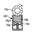
潤滑剤供給装置16は、固形潤滑剤16b、感光体ドラム11と固形潤滑剤16bとに摺接する潤滑剤供給ローラ16a(ブラシ状ローラ)、固形潤滑剤16bを保持する保持部材16c、保持部材16cを固形潤滑剤16bとともに収納するケース16f、保持部材16cとともに固形潤滑剤16bを潤滑剤供給ローラ16aに向けて付勢する回動部材16g及び引張スプリング16h(加圧機構)、潤滑剤供給ローラ16aによって感光体ドラム11上に供給された潤滑剤を薄層化するブレード状部材16d、等で構成される。なお、ブレード状部材16dは、潤滑剤供給ローラ16aに対して感光体ドラム11の回転方向下流側の位置で感光体ドラム11に対してカウンタ方向に当接するように構成されている。
このように構成された潤滑剤供給装置16によって、感光体ドラム11上に薄層化された潤滑剤が供給される。なお、潤滑剤供給装置16の構成・動作については、後で詳しく説明する。
The
The
図2にて、先に述べた作像プロセスをさらに詳しく説明する。
現像ローラ13aは、図2中の矢印方向(反時計方向)に回転している。現像部13内の現像剤は、間に仕切部材を介在するように配設された第1搬送スクリュ13b1及び第2搬送スクリュ13b2の回転によって、不図示のトナー補給部によってトナー容器28から補給されたトナーとともに撹拌混合されながら長手方向に循環する(図2の紙面垂直方向である。)。
The image forming process described above will be described in more detail with reference to FIG.
The developing
そして、摩擦帯電してキャリアに吸着したトナーは、キャリアとともに現像ローラ13a上に担持される。現像ローラ13a上に担持された現像剤は、その後にドクターブレード13cの位置に達する。そして、現像ローラ13a上の現像剤は、ドクターブレード13cの位置で適量に調整された後に、感光体ドラム11との対向位置(現像領域である。)に達する。
The toner that is frictionally charged and adsorbed on the carrier is carried on the developing
その後、現像領域において、現像剤中のトナーが、感光体ドラム11表面に形成された静電潜像に付着する。詳しくは、レーザ光Lが照射された画像部の潜像電位(露光電位)と、現像ローラ13aに印加された現像バイアスとの、電位差(現像ポテンシャル)によって形成される電界によって、トナーが潜像に付着する(トナー像が形成される)。
Thereafter, in the developing region, the toner in the developer adheres to the electrostatic latent image formed on the surface of the
その後、現像工程にて感光体ドラム11に付着したトナーは、そのほとんどが中間転写ベルト17上に転写される。そして、感光体ドラム11上に残存した未転写のトナーが、クリーニングブレード15aによってクリーニング部15内に回収される。
Thereafter, most of the toner adhering to the
ここで、図示は省略するが、装置本体1に設けられたトナー補給部は、交換自在に構成されたボトル状のトナー容器28と、トナー容器28を保持・回転駆動するとともに現像部13に新品トナーを補給するトナーホッパ部と、で構成されている。また、トナー容器28内には、新品のトナー(イエロー、マゼンタ、シアン、ブラックのいずれかである。)が収容されている。また、トナー容器28(トナーボトル)の内周面には、螺旋状の突起が形成されている。
Here, although not shown in the figure, the toner replenishing portion provided in the apparatus main body 1 includes a bottle-shaped
なお、トナー容器28内の新品トナーは、現像部13内のトナー(既設のトナーである。)の消費にともない、トナー補給口から現像部13内に適宜に補給されるものである。図示は省略するが、現像部13内のトナーの消費は、感光体ドラム11に対向する反射型フォトセンサと、現像部13の第2搬送スクリュ23b2の下方に設置された磁気センサと、によって間接的又は直接的に検知される。
The new toner in the
以下、本実施の形態1における、潤滑剤供給装置16(潤滑剤供給部)の構成・動作について詳しく説明する。
図2に示すように、潤滑剤供給装置16は、固形潤滑剤16b、感光体ドラム11と固形潤滑剤16bとに摺接するブラシ毛が周設された潤滑剤供給ローラ16a(ブラシ状ローラ)、固形潤滑剤16bを保持する保持部材16c、保持部材16cを固形潤滑剤16bとともに収納するケース16f、保持部材16cとともに固形潤滑剤16bを潤滑剤供給ローラ16aに向けて付勢する回動部材16g及び引張スプリング16h(加圧機構)、潤滑剤供給ローラ16aによって感光体ドラム11上に供給された潤滑剤を薄層化するブレード状部材16d(薄層化ブレード)、等で構成される。
Hereinafter, the configuration and operation of the lubricant supply device 16 (lubricant supply unit) in the first embodiment will be described in detail.
As shown in FIG. 2, the
ケース16fは、固形潤滑剤16bが潤滑剤供給ローラ16aに圧接する方向に移動できるように(移動を妨げないように)、保持部材16cを固形潤滑剤16bとともに収納する略箱状部材であって、潤滑剤供給装置16(プロセスカートリッジ10BK)に固定されている。ケース16fは、固形潤滑剤16bや保持部材16cの圧接方向(固形潤滑剤16bが潤滑剤供給ローラ16aを圧接する方向である。)の移動を妨げない範囲で、それらの部材16b、16cとの隙間が比較的小さく設定されていて、潤滑剤供給ローラ16aに対して固形潤滑剤16bが傾いて圧接するのをある程度防止する。
The
潤滑剤供給ローラ16a(ブラシ状ローラ)は、長さ(毛足)が0.2〜20mm(好ましくは、0.5〜10mm)の範囲のブラシ毛が基布上に植毛されたものを芯金上にスパイラル状に巻き付けたものである。
ブラシ毛の長さが20mmを超えると、経時における感光体ドラム11との繰り返し摺擦によって、ブラシ毛が所定方向に倒毛して、固形潤滑剤16bの掻取性や感光体ドラム11からのトナー除去性が低下してしまう。これに対して、ブラシ毛の長さが0.2mm未満であると、固形潤滑剤16bや感光体ドラム11に対する物理的な当接力が不足してしまう。したがって、ブラシ毛の長さは上述の範囲であることが好ましい。
The
When the length of the bristle exceeds 20 mm, the bristle falls in a predetermined direction due to repeated rubbing with the
潤滑剤供給ローラ16aは、図2の時計方向に回転する感光体ドラム11に対してカウンタ方向で接触するように回転する(図2の時計方向の回転である。)。また、潤滑剤供給ローラ16a(ブラシ毛)は、固形潤滑剤16bと感光体ドラム11とに摺接するように配置されていて、潤滑剤供給ローラ16aが回転することによって固形潤滑剤16bから潤滑剤を掻き取り、その掻き取った潤滑剤を感光体ドラム11との摺接位置まで搬送した後に、その潤滑剤を感光体ドラム11上に塗布する。
固形潤滑剤16bの後方部には,潤滑剤供給ローラ16aと固形潤滑剤16bとの接触ムラをなくすために加圧機構16g、16hが配置されていて、保持部材16cに保持(貼着)された状態の固形潤滑剤16bを潤滑剤供給ローラ16aに向けて付勢している。ここで、加圧機構は、保持部材16cに回動可能に支持された1対の回動部材16gと、1対の回動部材16gに連結された付勢部材としての引張スプリング16hと、で構成されているが、これについては後で詳しく説明する。
The
In order to eliminate uneven contact between the
本実施の形態1では、固形潤滑剤16bを主としてステアリン酸亜鉛で形成している。詳しくは、固形潤滑剤16bは、ステアリン酸亜鉛を主成分とする潤滑油添加剤を溶解したもので、塗りすぎによる副作用がなく、充分な潤滑性があるものが好適である。
ステアリン酸亜鉛は、代表的なラメラ結晶紛体である。ラメラ結晶は両親媒性分子が自己組織化した層状構造を有していて、せん断力が加わると層間にそって結晶が割れて滑りやすい。したがって、感光体ドラム11表面を低摩擦係化することができる。すなわち、せん断力を受けて均一に感光体ドラム11表面を覆っていくラメラ結晶によって、少量の潤滑剤によって効果的に感光体ドラム11表面を覆うことができる。
In the first embodiment, the
Zinc stearate is a typical lamellar crystal powder. A lamellar crystal has a layered structure in which amphiphilic molecules are self-organized, and when a shearing force is applied, the crystal breaks along the layers and is slippery. Therefore, the surface of the
なお、固形潤滑剤16bとしては、ステアリン酸亜鉛の他にも、ステアリン酸バリウム、ステアリン酸鉄、ステアリン酸ニッケル、ステアリン酸コバルト、ステアリン酸銅、ステアリン酸ストロンチュウム、ステアリン酸カルシウム等のステアリン酸基を有するものを用いることができる。また、同じ脂肪酸基であるオレイン酸亜鉛、オレイン酸バリウム、オレイン酸鉛、以下、ステアリン酸と同様の化合物や、パルチミン酸亜鉛、パルチミン酸バリウム、パルチミン酸鉛、以下、ステアリン酸と同様の化合物を使用して良い。他にも、脂肪酸基として、カプリル酸、リノレン酸、コリノレン酸等を使用することができる。さらに、カンデリラワックス、カンルナウバワックス、ライスワックス、木ろう、おおば油、みつろう、ラノリン等のワックスを使用することもできる。これらは有機系の固形潤滑剤となりやすく、トナーとの相性が良い。
As the
固形潤滑剤16bを潤滑剤供給ローラ16aを介して感光体ドラム11表面に塗布すると、感光体ドラム11表面には粉体状の潤滑剤が塗布されるが、この状態のままでは潤滑性は充分に発揮されないため、ブレード状部材16d(薄層化ブレード)が潤滑剤を均一化する部材として機能することになる。ブレード状部材16dにより、感光体ドラム11上での潤滑剤の皮膜化がおこなわれて、潤滑剤はその潤滑性を充分に発揮することになる。
このとき、潤滑剤供給ローラ16aにより塗布する粉体状の潤滑剤は微粉であるほど、ブレード状部材16dにより感光体ドラム11上に分子膜レベルで薄膜化される。
When the
At this time, the finer the powdery lubricant applied by the
以下、本実施の形態1において特徴的な、潤滑剤供給装置16の構成・動作について詳述する。
図3を参照して、本実施の形態1における潤滑剤供給装置16において、固形潤滑剤16bは、保持部材16cに貼着され保持されている。具体的に、保持部材16cと固形潤滑剤16bとの間に両面テープや接着剤等が介在されて、保持部材16cは固形潤滑剤16bを貼着して保持することになる。ここで、保持部材16cは、コの字状に曲げ加工された板金であって、その両側面に回動部材16gを保持するための複数の穴部16c2(軸受部)が形成されている。
Hereinafter, the configuration and operation of the
Referring to FIG. 3, in
ここで、図3、図4(A)、図6等を参照して、保持部材16cには、幅方向(図2の紙面垂直方向であって、図6の左右方向である。)の離れた位置に、1対の回動部材16g(押圧部材)がそれぞれ回動可能に支持されている。この1対の回動部材16gは、引張スプリング16h(付勢部材)による付勢力によってそれぞれ所定方向に回動して保持部材16cを介して固形潤滑剤16bを間接的に押圧して、固形潤滑剤16bを潤滑剤供給ローラ16aに圧接させるものである。
詳しくは、図4(A)、図5を参照して、回動部材16gの両側面には、回動中心となる支軸16g1(軸部)が形成されている。そして、この回動部材16gの支軸16g1が、保持部材16cの穴部16c2に挿着されて、回動部材16gが保持部材16cに回動可能に保持されることになる。なお、2つの回動部材16cは、それぞれ、図3及び図6に示すように、幅方向において左右対称になるように保持部材16cに設置される。
Here, referring to FIG. 3, FIG. 4 (A), FIG. 6, etc., the holding
Specifically, referring to FIG. 4A and FIG. 5, support shafts 16g1 (shaft portions) serving as rotation centers are formed on both side surfaces of the
また、図3、図6等を参照して、1対の回動部材16gは、付勢部材としての引張スプリング16hで連結されている。詳しくは、引張スプリング16hの両端のフック部が、それぞれ、回動部材16gの穴部16g4(図4(A)を参照できる。)に接続されている。
そして、この引張スプリング16hは、ケース16fに圧接するように1対の回動部材16gを互いに異なる方向に回動させて保持部材16cを潤滑剤供給ローラ16aに近づく方向に付勢する付勢部材として機能することになる。具体的に、引張スプリング16h(付勢部材)は、1対の回動部材16gがケース16fに圧接するカム形状部16g2の部分同士のスパンが漸減するように、1対の回動部材16gを回動させる。
すなわち、2つの回動部材16gは、ケース16fの内壁面に当接するカム形状部16g2(図4(A)等を参照できる。)が互いに近づく方向のスプリング力(付勢力)を引張スプリング16hから受ける。これにより、図6の左方の回動部材16gは、支軸16g1を回動中心として、図6の反時計方向に回動するように付勢される。これに対して、図6の右方の回動部材16gは、支軸16g1を回動中心として、図6の時計方向に回動するように付勢される。
3 and 6 and the like, the pair of rotating
The
That is, the two
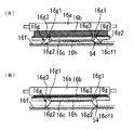
さらに詳しくは、図6(A)〜(C)に示すように、画像形成装置1における累積稼働時間の増加とともに、固形潤滑剤16bは、潤滑剤供給ローラ16aへの潤滑剤供給によって徐々に消費されて、その厚さ(潤滑剤供給ローラ16aへの圧接方向の厚さである。)が薄くなっていく。そして、一対の回動部材16gは、それぞれ、こうした固形潤滑剤16bの消費(薄肉化)にともない、引張スプリング16hによる付勢力によって上述した方向に回動することになる。
換言すると、一対の回動部材16gに形成されたカム形状部16g2は、それぞれ、固形潤滑剤16bの消費にともない保持部材16cが固形潤滑剤16bとともに潤滑剤供給ローラ16aに近づく方向に移動するように引張スプリング16hによる付勢力によって回動してケース16fに圧接することになる。
このように1対の回動部材16gが回動するとき、その回動(固形潤滑剤16bの消費)にともない、回動部材16g(カム形状部16g2)がケース16fに当接する位置(作用点)と支軸16g1(支点)とを結ぶ仮想線分と、保持部材16c(固形潤滑剤16b)が移動する圧接方向の仮想直線と、がなす回動方向の角度が漸減することになる。また、回動(固形潤滑剤16bの消費)にともない、引張スプリング16hの付勢力を受ける回動部材16gの位置(力点)と支軸16g1(支点)とを結ぶ仮想線分と、引張スプリング16hの付勢力が作用する付勢方向の仮想直線と、がなす回動方向の角度が漸増することになる。
More specifically, as shown in FIGS. 6A to 6C, as the cumulative operation time in the image forming apparatus 1 increases, the
In other words, the cam-shaped portions 16g2 formed on the pair of rotating
Thus, when the pair of rotating
ここで、本実施の形態1では、上述したように1対の回動部材16gが回動して双方のスパンが所定値以下になったとき(回動部材16gが所定の回動範囲を超えたとき)に、1対の回動部材16gのうち一方の回動部材16gと引張スプリング16hとの連結が解除されるように形成されている。
具体的に、図4に示すように、1対の回動部材16gのうち一方の回動部材16gに、穴部16g4(引張スプリング16hのフック部を接続するための穴部である。)に繋がる切欠16g5が形成されている。これにより、図4(A)、図6(A)、(B)に示すように、回動部材16gが所定の回動範囲に達するまでは、回動部材16gの穴部16g4に引張スプリング16hのフック部が接続された状態(引張スプリング16hが連結された状態)が維持される。これに対して、図4(B)、図6(C)に示すように、回動部材16gが所定の回動範囲を超えると、切欠16g5の位置が引張スプリング16hの付勢方向に一致して、回動部材16gの穴部16g4から切欠16g5を介して引張スプリング16hのフック部が外れた状態(引張スプリング16hの連結が解除された状態)になる。なお、図示は省略するが、1対の回動部材16gのうち、もう一方の回動部材16gには、穴部16g4に切欠16g5は設けられていない。
Here, in the first embodiment, as described above, when the pair of rotating
Specifically, as shown in FIG. 4, the hole 16g4 (a hole for connecting the hook portion of the
このように、回動部材16gから引張スプリング16hが脱落したとき、固形潤滑剤16bは充分に消費されて薄肉化した状態(交換メンテナンスが必要な状態)になっている。逆に言うと、固形潤滑剤16bが充分に消費されて薄肉化した状態(交換メンテナンスが必要な状態)に合わせて、回動部材16gから引張スプリング16hが脱落するように、回動部材16gにおける切欠16g5の位置が定められている。このようなメカニズムが成立するのは、回動部材16gの回動方向の姿勢(回動角度)と、固形潤滑剤16bの肉厚(消費量)と、に相関があることによるものである。すなわち、回動部材16gの回動角度(初期状態からの回動角度)が大きくなるにつれて、固形潤滑剤16bの肉厚が比例的に小さくなることになる。
Thus, when the
そして、本実施の形態1では、回動部材16gが所定の回動範囲を超える位置まで回動したことを検知することにより固形潤滑剤16bの交換時期を検知する検知手段を設けている。詳しくは、検知手段は、回動部材16gと引張スプリング16hとの連結が解除された状態(図4(B)、図6(C)の状態である。)を検知することになる。
具体的に、図6を参照して、本実施の形態1では、潤滑剤供給ローラ16a
を駆動する駆動モータ30に供給される電流値の変化を検知する電流検知部31が設けられている。そして、この電流検知部31が、回動部材16gと引張スプリング16hとの連結が解除された状態を検知する検知手段として機能することになる。すなわち、図6(C)のように、回動部材16gから引張スプリング16hが脱落したときには、その直前の状態(脱落していない状態)に比べて、固形潤滑剤16bに対する回動部材16gの押圧力が激減して、潤滑剤供給ローラ16aを回転駆動するための負荷も激減するため、電流検知部31で検知される電流値が著しく低下することになる。このように電流検知部31にて検知される電流値が大きく減少するタイミングを検知することで、固形潤滑剤16bの交換時期(固形潤滑剤16bが薄肉化して、回動部材16gと引張スプリング16hとの連結が解除された状態)が検知されることになる。
And in this Embodiment 1, the detection means which detects the replacement time of the
Specifically, referring to FIG. 6, in the first embodiment,
A
以下、図6(A)〜(C)を用いて、固形潤滑剤16bの消費(薄肉化)にともなう回動部材16gの動作について詳述する。
まず、図6(A)に示すように、新品状態の固形潤滑剤16b(保持部材16cに貼着・保持された状態のものである。)が潤滑剤供給装置16(装置本体1)にセットされると、1対の回動部材16gのカム形状部16g2のスパン(ケース16fとの2つの圧接部同士間の幅方向の距離である。)が最長となる状態で、保持部材16c(加圧機構16g、16h)によって固形潤滑剤16bが潤滑剤供給ローラ16aに圧接する。そして、この状態で、潤滑剤供給装置16(潤滑剤供給ローラ16a)による感光体ドラム11上への潤滑剤の供給が開始される。なお、支軸16g1がスライド移動できるように穴部16c2を長穴とするとともに、回動部材16gの押圧部16g3(図4(A)を参照できる。)が保持部材16cの内部の天井面を押圧するように構成することもできる。
その後、図6(B)に示すように、経時において、潤滑剤供給装置16(潤滑剤供給ローラ16a)による感光体ドラム11上への潤滑剤の供給が進められると、1対の回動部材16gのカム形状部16g2のスパンが徐々に漸減して、その状態で保持部材16c(加圧機構16g、16h)によって固形潤滑剤16bが潤滑剤供給ローラ16aに圧接する。
Hereinafter, the operation of the rotating
First, as shown in FIG. 6A, a new
Thereafter, as shown in FIG. 6B, when the supply of the lubricant onto the
そして、最終的に、図6(C)に示すように、潤滑剤供給装置16(潤滑剤供給ローラ16a)による感光体ドラム11上への潤滑剤の供給がさらに進められて、固形潤滑剤16bの肉厚が僅かになった状態で、一方の回動部材16gから引張スプリング16hが脱落して、そのときの負荷変動を電流検知部31が検知する。そして、このときの電流検知部31における検知に基いて、装置本体1における表示パネル(不図示である。)に固形潤滑剤16bの交換を促す旨の表示がされるとともに、画像形成装置1におけるその後の画像形成動作を中止するように制御する。そして、固形潤滑剤16bが保持部材16cとともに潤滑剤供給装置16(装置本体1)から取出されて、固形潤滑剤16bの交換メンテナンスがおこなわれることになる。
Finally, as shown in FIG. 6C, the supply of the lubricant onto the
このように、本実施の形態1では、固形潤滑剤16bの肉厚(消費量)の変化にともない変化する回動部材16gの回動方向の位置(回動角度)を検知して、固形潤滑剤16bの消費の程度を判断しているため、固形潤滑剤16bの交換時期を正確に検知することができる。すなわち、画像形成装置1におけるプリント動作の差異(例えば、1枚のみのプリントが多くされたり連続プリントが多くされたりする等の使用状況の差異である。)や固形潤滑剤16b自体の差異等に関係することなく、固形潤滑剤16bの交換時期を正確に検知することができる。そのため、固形潤滑剤16bの交換時期を早めに検知してしまって使用可能な固形潤滑剤16bを無駄に交換してしまう不具合や、固形潤滑剤16bの交換時期を遅めに検知してしまって感光体ドラム11上に供給する潤滑剤が不足してしまう不具合を抑止することができる。
特に、本実施の形態1では、回動部材16gから引張スプリング16hを脱落させて潤滑剤供給ローラ16aに対する固形潤滑剤16bの圧接力を低下させてしまっているものの、その直前までは潤滑剤供給ローラ16aに対する固形潤滑剤16bの圧接力を低下させることなく固形潤滑剤16bの交換時期を検知しているため感光体ドラム11上に供給する潤滑剤が不足して異常画像が生じてしまう不具合が抑止される。また、回動部材16gから引張スプリング16hを脱落させて固形潤滑剤16bの交換時期を検知した直後に画像形成動作を中止しているために、感光体ドラム11上に供給する潤滑剤が不足して異常画像が生じてしまう不具合は抑止されることになる。
Thus, in this Embodiment 1, the position (rotation angle) of the rotation direction of the
In particular, in the first embodiment, the
なお、本実施の形態1では、2つの回動部材16gのうち一方の回動部材16gの側で引張スプリング16hが脱落するように構成したが、2つの回動部材16gの双方の側で引張スプリング16hが脱落するように構成することもできる。
また、駆動モータ30は、潤滑剤供給ローラ16aを単独で駆動するものであってもよいし、感光体ドラム11等の他の回転部材とともに潤滑剤供給ローラ16aを駆動するものであってもよい。そして、いずれの場合であっても、回動部材16gから引張スプリング16hが脱落した際の負荷変動を電流検知部31(検知手段)で確実に検知することができる。
In the first embodiment, the
Further, the
なお、本実施の形態1では、回動部材16gから引張スプリング16hが脱落した状態を電流検知部31によって検知した。
これに対して、引張スプリング16hと1対の回動部材16gとを、いずれも、金属材料等の導電性材料で形成して、1対の回動部材16g同士が導通状態から非導通状態に変化する状態を検知することにより、回動部材16gから引張スプリング16hが脱落した状態を検知することもできる。
具体的に、図7に示すように、ケース16fの底面には、2つの回動部材16gのカム形状部16g2が圧接する部分に、それぞれ金属パッド36が設置されている。さらに、その2つの金属パッド36の間の導通状態を検知する導通検知部35が設置されている。そして、図7(A)、(B)のように回動部材16gに引張スプリング16hが連結されている状態では、2つの金属パッド36の間が、導電性材料で形成された2つの回動部材16gと引張スプリング16hとを介して導通状態であることが導通検知部35によって検知される。これに対して、図7(C)のように回動部材16gに引張スプリング16hが連結されていない状態では、2つの金属パッド36の間の導通経路が遮断されて非導通状態であることが導通検知部35によって検知される。なお、導通検知部35としては、例えば、2つの金属パッド36の間に微電流を一方向に流して、その電流が正常に流れているか否かを検知するものを用いることができる。また、図7(A)〜(C)に示した回動部材16gの動作は、先に説明した図6(A)〜(C)に対応するものであるので、その詳細説明を省略する。
In the first embodiment, the
In contrast, the
Specifically, as shown in FIG. 7,
以上説明したように、本実施の形態1によれば、固形潤滑剤16bを保持する保持部材16cに回動可能に支持された回動部材16gが所定の回動範囲を超える位置まで回動したことを検知することにより、固形潤滑剤16bの交換時期を検知している。これにより、経時においても感光体ドラム11(像担持体)に供給する潤滑剤が不足することなく、常に安定して均一に感光体ドラム11上に潤滑剤を供給することができて、固形潤滑剤16bの交換時期を正確に検知することができる。
As described above, according to the first embodiment, the rotating
実施の形態2.
図8〜図10にて、この発明の実施の形態2について詳細に説明する。
図8は、実施の形態2における潤滑剤供給装置16を示す図であって、前記実施の形態1における図6(A)に相当する図である。図9は、固形潤滑剤16bの交換時期を検知したときの状態を示す図であって、前記実施の形態1における図6(C)に相当する図である。さらに、図10は、変形例として別形態の潤滑剤供給装置16を示す図であって、前記実施の形態1における図6(A)に相当する図である。
本実施の形態2における潤滑剤供給装置16は、固形潤滑剤の交換時期を検知する検知手段の構成が、前記実施の形態1のものとは相違する。
Embodiment 2. FIG.
A second embodiment of the present invention will be described in detail with reference to FIGS.
FIG. 8 is a diagram illustrating the
The
本実施の形態2における潤滑剤供給装置16も、前記実施の形態1のものと同様に、固形潤滑剤16b、潤滑剤供給ローラ16a(ブラシ状ローラ)、固形潤滑剤16bを保持する保持部材16c、保持部材16cを固形潤滑剤16bとともに収納するケース16f、保持部材16cとともに固形潤滑剤16bを潤滑剤供給ローラ16aに向けて付勢する回動部材16g及び引張スプリング16h(加圧機構)、等で構成される。
Similarly to the first embodiment, the
ここで、図8を参照して、本実施の形態2における潤滑剤供給装置16は、回動部材16gのカム形状部16g2が、金属材料等の導電性材料で形成されている。また、本実施の形態2における回動部材16gには、前記実施の形態1のものとは異なり、穴部16g4に切欠16g5は形成されていない。すなわち、本実施の形態2では、回動部材16gが所定の回動範囲を超えても引張スプリング16hの脱落が生じないように構成されている。このことは、後述する実施の形態3、4においても同様である。
Here, referring to FIG. 8, in
また、本実施の形態2における潤滑剤供給装置16は、ケース16fにおいて、回動部材16gのカム形状部16g2が圧接する位置に電極部45、47、48が設けられている。特に、一方の回動部材16g(図8の右方の回動部材16gである。)の側には、カム形状部16g2が回動する方向に沿うように2つの電極部47、48が設置されている。この2つの電極部47、48は、その境界部分が絶縁されている。
Further, in the
さらに、これらの電極部45、47、48と、2つのカム形状部16g2と、電源部40と、ヒューズ41と、が接続された電気回路(図8中の破線で示す回路である。)が形成されている。そして、この電気回路は、右方の回動部材16gが所定の回動範囲を超えてカム形状部16g2が2つの電極部47、48のうち1つの電極部47に圧接したときに、電気回路における電気抵抗が減少してヒューズ41に流れる電流が増大するように形成されている。すなわち、この電気回路は、右方の回動部材16gが所定の回動範囲を超えずにカム形状部16g2が第1の電極部48に接しているとき(図8の状態である。)には所定の抵抗42を介して大きな電流が流れずに、右方の回動部材16gが所定の回動範囲を超えてカム形状部16g2が第2の電極部47に接しているとき(図9の状態であって、固形潤滑剤16gの交換時期に対応するように設定されている。)には所定の抵抗42を介することなく大きな電流(過電流)が流れるように構成されている。そして、図9の状態で電気回路中に過電流が流れたときに、ヒューズ41が切れた状態になり、その状態を電源部40に内蔵された電流検知部が検知することで、固形潤滑剤16bの交換時期を判断することになる。すなわち、本実施の形態2では、固形潤滑剤16bの交換時期を検知する検知手段は、電気回路に設置されたヒューズ41が切れた状態を検知することになる。
Furthermore, an electric circuit (a circuit indicated by a broken line in FIG. 8) in which these
なお、本実施の形態2では、ヒューズ41をケース16fに設置したが、図10に示すように、ヒューズ41を保持部材16cに設置することもできる。その場合、固形潤滑剤16bの交換メンテナンス時において、ヒューズ41が保持部材16cとともに装置本体1(潤滑剤供給装置16)から取出されることになるため、ヒューズ41の交換メンテナンスの作業性も向上することになる。
また、本実施の形態2では、電気回路を流れる電流を可変するために2つの電極部47、48を設置したが、3つ以上の電極部を設置して電気回路を流れる電流を段階的に可変することもできる。
In the second embodiment, the
In the second embodiment, the two
以上説明したように、本実施の形態2においても、前記実施の形態1と同様に、固形潤滑剤16bを保持する保持部材16cに回動可能に支持された回動部材16gが所定の回動範囲を超える位置まで回動したことを検知することにより、固形潤滑剤16bの交換時期を検知している。これにより、経時においても感光体ドラム11(像担持体)に供給する潤滑剤が不足することなく、常に安定して均一に感光体ドラム11上に潤滑剤を供給することができて、固形潤滑剤16bの交換時期を正確に検知することができる。
As described above, also in the second embodiment, similarly to the first embodiment, the rotating
実施の形態3.
図11〜図13にて、この発明の実施の形態3について詳細に説明する。
図11(A)は、実施の形態3における潤滑剤供給装置16を示す正面図であって、前記実施の形態1における図5に相当する図である。図11(B)は、図11(A)の潤滑剤供給装置16において固形潤滑剤16bの交換時期を検知したときの状態を示す正面図である。また、図12(A)は図11(A)の状態にある潤滑剤供給装置16を幅方向にみた図であり、図12(B)は図11(B)の状態にある潤滑剤供給装置16を幅方向にみた図である。さらに、図13は変形例として別形態の潤滑剤供給装置16を示す正面図であって、図13(A)が本実施の形態3における図11(A)に相当する図であり、図13(B)が本実施の形態3における図11(B)に相当する図である。
本実施の形態3における潤滑剤供給装置16は、固形潤滑剤の交換時期を検知する検知手段の構成が、前記実施の形態1のものとは相違する。
Embodiment 3 FIG.
A third embodiment of the present invention will be described in detail with reference to FIGS.
FIG. 11A is a front view showing the
The
本実施の形態3における潤滑剤供給装置16も、前記各実施の形態のものと同様に、固形潤滑剤16b、潤滑剤供給ローラ16a(ブラシ状ローラ)、固形潤滑剤16bを保持する保持部材16c、保持部材16cを固形潤滑剤16bとともに収納するケース16f、保持部材16cとともに固形潤滑剤16bを潤滑剤供給ローラ16aに向けて付勢する回動部材16g及び引張スプリング16h(加圧機構)、等で構成される。
The
ここで、図11、図12を参照して、本実施の形態3における潤滑剤供給装置16は、ケース16fに、回動部材16gの両側面にそれぞれ対向するように(回動部材16gを挟むように)、凹状部16f1(ガイド部)が形成されている。さらに、その凹状部16f1には、それぞれの対向面の間に、導線54(線状の導電体)が張架されている。この導線54としては、銅、ニッケル、又は、それらの合金等の金属材料で形成されたものや、その表面に非導電材料が被覆されたものや、湿潤木綿や炭素材等の非金属材料で形成されたもの、等を用いることができる。そして、図11に示すように、導線54は、電源部50や電流検知部51を有する電気回路(図中の破線で示す回路である。)に接続されている。
Here, referring to FIG. 11 and FIG. 12, the
そして、この導線54は、右方の回動部材16gが所定の回動範囲を超えたときに、カム形状部16g2に接触して破断(断線)するように形成されている。すなわち、右方の回動部材16gが所定の回動範囲を超えずにカム形状部16g2が導線54に接していない(又は、軽接触している)とき(図11(A)、図12(A)の状態である。)には導線54が断線せずに電気回路に電流が流れて、右方の回動部材16gが所定の回動範囲を超えてカム形状部16g2が導線54に接する(又は、強く接触する)とき(図11(B)、図12(B)の状態であって、固形潤滑剤16gの交換時期に対応するように設定されている。)には導線54が断線して電気回路に電流が流れないように構成されている。そして、図11(B)、図12(B)のように導線54が破断したときに、電気回路に電流が流れない状態になり、その状態を電流検知部51が検知することで、固形潤滑剤16bの交換時期を判断することになる。すなわち、本実施の形態3では、固形潤滑剤16bの交換時期を検知する検知手段は、回動部材16gが所定の回動範囲を超えて導線54を破断したときに電気回路に流れる電流の変化を検知することになる。
ここで、上述したように導線54の破断を確実におこなうために、カム形状部16g2にナイフエッジ部を設けたり、カム形状部16g2を高硬度材料で形成したりすることが好ましい。
And this
Here, as described above, in order to reliably break the
なお、本実施の形態3において、ケース16fに設けた凹状部16f1は、保持部材16cに回動可能に支持された1対の回動部材16gの面倒れを防止するガイド部としても機能する。
すなわち、凹状部16f1は、回動部材16gを挟むように、回動部材16gの両側面にそれぞれ対向するように形成されているため、回動部材16gが凹状部16f1にガイドされるように回動することになる。このような構成により、回動部材16gに面倒れ(図11において、回動部材16gが時計方向又は反時計方向に傾斜する現象である。)が生じる不具合が確実に抑止されることになる。
In the third embodiment, the recessed portion 16f1 provided in the
That is, since the concave portion 16f1 is formed so as to face both side surfaces of the rotating
なお、本実施の形態3では、ケース16fの凹状部16f1に導線54を設けたが、図13に示すように、ケース16fの凹状部16f1の同じ位置にフォトセンサ55(発光素子55aと受光素子55bとからなる。)を設けることもできる。
具体的に、図13に示すように、ケース16fの凹状部16f1には、一方の対向面に発光素子55aが設置され、他方の対向面に受光素子55bが設置されている。そして、回動部材16gが所定の回動範囲を超えずにカム形状部16g2によって発光素子55aから射出される光が遮られないとき(図13(A)の状態である。)には受光素子55bが受光して、回動部材16gが所定の回動範囲を超えてカム形状部16g2によって発光素子55aから射出される光が遮られるとき(図13(B)の状態であって、固形潤滑剤16gの交換時期に対応するように設定されている。)には受光素子55bが受光しないように構成されている。そして、図13(B)のように回動部材16gが所定の回動範囲を超えた状態を、凹状部16f1の位置でフォトセンサ55(検知手段)が光学的に検知することで、固形潤滑剤16bの交換時期を判断することになる。
In the third embodiment, the
Specifically, as shown in FIG. 13, in the concave portion 16f1 of the
以上説明したように、本実施の形態3においても、前記各実施の形態と同様に、固形潤滑剤16bを保持する保持部材16cに回動可能に支持された回動部材16gが所定の回動範囲を超える位置まで回動したことを検知することにより、固形潤滑剤16bの交換時期を検知している。これにより、経時においても感光体ドラム11(像担持体)に供給する潤滑剤が不足することなく、常に安定して均一に感光体ドラム11上に潤滑剤を供給することができて、固形潤滑剤16bの交換時期を正確に検知することができる。
As described above, also in the third embodiment, the rotating
実施の形態4.
図14及び図15にて、この発明の実施の形態4について詳細に説明する。
図14(A)は、実施の形態4における潤滑剤供給装置16を示す正面図であって、前記実施の形態3における図11(A)に相当する図である。図14(B)は、図14(A)の潤滑剤供給装置16において固形潤滑剤16bの交換時期を検知したときの状態を示す正面図であって、前記実施の形態3における図11(B)に相当する図である。また、図15(A)は図14(A)の状態にある潤滑剤供給装置16を幅方向にみた図であり、図15(B)は図14(B)の状態にある潤滑剤供給装置16を幅方向にみた図である。
本実施の形態4における潤滑剤供給装置16は、固形潤滑剤の交換時期を検知する検知手段の構成が、前記実施の形態1のものとは相違する。
A fourth embodiment of the present invention will be described in detail with reference to FIGS.
FIG. 14 (A) is a front view showing the
The
本実施の形態4における潤滑剤供給装置16も、前記各実施の形態のものと同様に、固形潤滑剤16b、潤滑剤供給ローラ16a(ブラシ状ローラ)、固形潤滑剤16bを保持する保持部材16c、保持部材16cを固形潤滑剤16bとともに収納するケース16f、保持部材16cとともに固形潤滑剤16bを潤滑剤供給ローラ16aに向けて付勢する回動部材16g及び引張スプリング16h(加圧機構)、等で構成される。
The
また、図14、図15を参照して、本実施の形態4における潤滑剤供給装置16にも、前記実施の形態3のものと同様に、導線57が設置されている。
ここで、本実施の形態4では、導線57が、ケース16fと回動部材16gとの間に、所定のテンションで接続されている。そして、この導線57は、図14に示すように、電源部50や電流検知部51を有する電気回路(図中の破線で示す回路である。)に接続されている。
Referring to FIGS. 14 and 15, similarly to the third embodiment,
Here, in
そして、この導線57は、右方の回動部材16gが所定の回動範囲を超えたときに、そのテンションが許容値を超えて破断(断線)するように形成されている。すなわち、右方の回動部材16gが所定の回動範囲を超えずに導線57のテンションが低いとき(図14(A)、図15(A)の状態である。)には導線57が断線せずに電気回路に電流が流れて、右方の回動部材16gが所定の回動範囲を超えて導線57のテンションが許容値を超えたとき(図14(B)、図15(B)の状態であって、固形潤滑剤16gの交換時期に対応するように設定されている。)には導線57が断線して電気回路に電流が流れないように構成されている。そして、図14(B)、図15(B)のように導線57が破断したときに、電気回路に電流が流れない状態になり、その状態を電流検知部51が検知することで、固形潤滑剤16bの交換時期を判断することになる。すなわち、本実施の形態4では、固形潤滑剤16bの交換時期を検知する検知手段は、回動部材16gが所定の回動範囲を超えて導線57を破断したときに電気回路に流れる電流の変化を検知することになる。
And this
以上説明したように、本実施の形態4においても、前記各実施の形態と同様に、固形潤滑剤16bを保持する保持部材16cに回動可能に支持された回動部材16gが所定の回動範囲を超える位置まで回動したことを検知することにより、固形潤滑剤16bの交換時期を検知している。これにより、経時においても感光体ドラム11(像担持体)に供給する潤滑剤が不足することなく、常に安定して均一に感光体ドラム11上に潤滑剤を供給することができて、固形潤滑剤16bの交換時期を正確に検知することができる。
As described above, also in the fourth embodiment, the rotating
なお、前記各実施の形態では、作像部における各部(感光体ドラム11、帯電部12、現像部13、クリーニング部15、潤滑剤供給装置16である。)を一体化してプロセスカートリッジ10Y、10M、10C、10BKを構成して、作像部のコンパクト化とメンテナンス作業性の向上とを図っている。
これに対して、作像部における各部11、12、13、15、16をプロセスカートリッジの構成部材とせずに、それぞれ単体で装置本体1に交換自在に設置されるように構成することもできる。このような場合にも、前記各実施の形態と同様の効果を得ることができる。
また、前記各実施の形態では、2成分現像剤を用いる2成分現像方式の現像部13が搭載された画像形成装置に対して本発明を適用したが、1成分現像剤を用いる1成分現像方式の現像部13が搭載された画像形成装置に対しても当然に本発明を適用することができる。
In each of the above embodiments, the
In contrast, each of the
In each of the above embodiments, the present invention is applied to the image forming apparatus in which the developing unit 13 of the two-component developing system using the two-component developer is mounted. However, the one-component developing system using the one-component developer is used. Naturally, the present invention can also be applied to an image forming apparatus having the developing unit 13 mounted thereon.
また、前記各実施の形態では、中間転写ベルト17を用いたタンデム型のカラー画像形成装置に対して本発明を適用した。これに対して、転写搬送ベルトを用いたタンデム型のカラー画像形成装置(転写搬送ベルトに対向するように並設された複数の感光体ドラム上のトナー像を、転写搬送ベルトによって搬送される記録媒体上に重ねて転写する装置である。)や、モノクロ画像形成装置等、その他の画像形成装置に対しても、本発明を適用することができる。そして、このような場合であっても、前記各実施の形態と同様の効果を得ることができる。
In each of the above embodiments, the present invention is applied to a tandem type color image forming apparatus using the
また、前記各実施の形態では、像担持体としての感光体ドラム11上に潤滑剤を供給する潤滑剤供給装置16に対して本発明を適用したが、感光体ドラム11以外の像担持体に潤滑剤を供給する潤滑剤供給装置(例えば、中間転写ベルト17に潤滑剤を供給する潤滑剤供給装置である。)に対しても当然に本発明を適用することができる。そして、このような場合であっても、前記各実施の形態と同様に検知手段を設けることで、前記各実施の形態と同様の効果を得ることができる。
In each of the above embodiments, the present invention is applied to the
また、前記各実施の形態では、潤滑剤供給ローラ16aとしてブラシ毛が周設されたブラシ状ローラを用いたが、潤滑剤供給ローラ16aとしてスポンジ状部材(弾性材料)が周設されたスポンジ状ローラを用いることもできる。そして、このような場合であっても、前記各実施の形態と同様に検知手段を設けることで、前記各実施の形態と同様の効果を得ることができる。
In each of the above-described embodiments, a brush-like roller having brush bristles is used as the
また、前記各実施の形態では、固形潤滑剤16bとともに保持部材16cを収納するようにケース16fを構成したが、その他の部材をも収納するようにケースを構成することもできる。例えば、潤滑剤供給装置16全体の筐体ケース(ハウジング)として、ケースを構成してもよい。そして、このような場合であっても、前記各実施の形態と同様に検知手段を設けることで、前記各実施の形態と同様の効果を得ることができる。
In each of the above embodiments, the
なお、本発明が前記各実施の形態に限定されず、本発明の技術思想の範囲内において、前記各実施の形態の中で示唆した以外にも、前記各実施の形態は適宜変更され得ることは明らかである。また、前記構成部材の数、位置、形状等は前記各実施の形態に限定されず、本発明を実施する上で好適な数、位置、形状等にすることができる。 It should be noted that the present invention is not limited to the above-described embodiments, and within the scope of the technical idea of the present invention, the embodiments can be modified as appropriate in addition to those suggested in the embodiments. Is clear. In addition, the number, position, shape, and the like of the constituent members are not limited to the above embodiments, and can be set to a number, position, shape, and the like that are suitable for carrying out the present invention.
1 画像形成装置本体(装置本体)、
11 感光体ドラム(像担持体)、
15 クリーニング部、
16 潤滑剤供給装置(潤滑剤供給部)、
16a 潤滑剤供給ローラ(ブラシ状ローラ)、
16b 固形潤滑剤、
16c 保持部材、
16f ケース、
16f1 凹状部(ガイド部)、
16g 回動部材(押圧部材)、
16g1 支軸(回動中心)、
16g2 カム形状部、
16h 引張スプリング(付勢部材)、
30 駆動モータ、
31、51 電流検知部(検知手段)、
35 導通検知部(検知手段)、
36 金属パッド、
41 ヒューズ、
54、57 導線、
55 フォトセンサ(検知手段)。
1 image forming apparatus body (apparatus body),
11 Photosensitive drum (image carrier),
15 Cleaning section,
16 Lubricant supply device (lubricant supply unit),
16a Lubricant supply roller (brush roller),
16b solid lubricant,
16c holding member,
16f case,
16f1 concave portion (guide portion),
16g rotating member (pressing member),
16g1 spindle (rotation center),
16g2 cam shape part,
16h tension spring (biasing member),
30 drive motor,
31, 51 Current detection part (detection means),
35 continuity detector (detector),
36 metal pads,
41 fuse,
54, 57 lead wires,
55 Photosensor (detection means).
Claims (8)
所定方向に回転するとともに、前記像担持体に摺接する潤滑剤供給ローラと、
前記潤滑剤供給ローラに摺接する固形潤滑剤と、
幅方向の離れた位置にそれぞれ回動可能に支持された1対の回動部材と、
前記1対の回動部材を互いに異なる方向に回動させて前記固形潤滑剤を前記潤滑剤供給ローラに近づく方向に付勢する付勢部材と、
前記回動部材が所定の回動範囲を超える位置まで回動したことを検知することにより前記固形潤滑剤の交換時期を検知する検知手段と、
を備え、
前記付勢部材は、前記1対の回動部材に連結されて、前記1対の回動部材が被圧接部に圧接する部分同士のスパンが漸減するように前記1対の回動部材を回動させる引張スプリングであって、
前記1対の回動部材が回動して前記スパンが所定値以下になったときに、前記1対の回動部材のうち少なくとも一方の回動部材と前記引張スプリングとの連結が解除されるように形成され、
前記検知手段は、前記回動部材と前記引張スプリングとの連結が解除された状態を検知することを特徴とする画像形成装置。 An image forming apparatus for supplying a lubricant onto an image carrier on which a toner image is carried,
A lubricant supply roller that rotates in a predetermined direction and is in sliding contact with the image carrier;
A solid lubricant in sliding contact with the lubricant supply roller;
A pair of rotating members supported rotatably at respective positions separated in the width direction;
A biasing member that rotates the pair of rotating members in different directions to bias the solid lubricant in a direction approaching the lubricant supply roller;
Detecting means for detecting the replacement timing of the solid lubricant by detecting that the rotating member has rotated to a position exceeding a predetermined rotation range;
Equipped with a,
The biasing member is connected to the pair of rotating members, and rotates the pair of rotating members so that a span between portions where the pair of rotating members are pressed against the pressed contact portions is gradually reduced. A tension spring to be moved,
When the pair of rotating members rotate and the span becomes a predetermined value or less, the connection between at least one of the pair of rotating members and the tension spring is released. Formed as
The image forming apparatus according to claim 1, wherein the detecting unit detects a state where the connection between the rotating member and the tension spring is released.
前記検知手段は、前記1対の回動部材同士が導通状態から非導通状態に変化する状態を検知することにより、前記回動部材と前記引張スプリングとの連結が解除された状態を検知することを特徴とする請求項1に記載の画像形成装置。The detecting means detects a state where the connection between the rotating member and the tension spring is released by detecting a state in which the pair of rotating members change from a conductive state to a non-conductive state. The image forming apparatus according to claim 1.
所定方向に回転するとともに、前記像担持体に摺接する潤滑剤供給ローラと、A lubricant supply roller that rotates in a predetermined direction and is in sliding contact with the image carrier;
前記潤滑剤供給ローラに摺接する固形潤滑剤と、A solid lubricant in sliding contact with the lubricant supply roller;
幅方向の離れた位置にそれぞれ回動可能に支持された1対の回動部材と、A pair of rotating members supported rotatably at respective positions separated in the width direction;
前記1対の回動部材を互いに異なる方向に回動させて前記固形潤滑剤を前記潤滑剤供給ローラに近づく方向に付勢する付勢部材と、A biasing member that rotates the pair of rotating members in different directions to bias the solid lubricant in a direction approaching the lubricant supply roller;
前記固形潤滑剤を保持する保持部材と、A holding member for holding the solid lubricant;
前記固形潤滑剤が前記潤滑剤供給ローラに圧接する方向に移動できるように少なくとも前記保持部材を前記固形潤滑剤とともに収納するように形成されたケースと、A case formed so as to accommodate at least the holding member together with the solid lubricant so that the solid lubricant can move in a direction in pressure contact with the lubricant supply roller;
前記回動部材が所定の回動範囲を超える位置まで回動したことを検知することにより前記固形潤滑剤の交換時期を検知する検知手段と、Detecting means for detecting the replacement timing of the solid lubricant by detecting that the rotating member has rotated to a position exceeding a predetermined rotation range;
を備え、With
前記1対の回動部材は、それぞれ、前記保持部材に支持され、前記固形潤滑剤の消費にともない前記保持部材が前記固形潤滑剤とともに前記潤滑剤供給ローラに近づく方向に移動するように前記付勢部材による付勢力によって回動して前記ケースに圧接するカム形状部を具備し、Each of the pair of rotating members is supported by the holding member, and the attachment member is moved so that the holding member moves together with the solid lubricant in a direction approaching the lubricant supply roller as the solid lubricant is consumed. A cam-shaped portion that is rotated by the urging force of the urging member and press-contacts the case;
前記カム形状部は、導電性材料で形成され、The cam-shaped portion is formed of a conductive material,
前記ケースは、前記1対の回動部材のうち少なくとも一方の回動部材の前記カム形状部が圧接する位置であって当該カム形状部が回動する方向に沿うように複数の電極部を具備し、The case includes a plurality of electrode portions at a position where the cam-shaped portion of at least one rotating member of the pair of rotating members is in pressure contact and along a direction in which the cam-shaped portion rotates. And
前記1対の回動部材の前記カム形状部と、前記複数の電極部と、電源部と、ヒューズと、が接続された電気回路をさらに備え、An electric circuit in which the cam-shaped portion of the pair of rotating members, the plurality of electrode portions, a power supply portion, and a fuse are connected;
前記電気回路は、前記回動部材が前記所定の回動範囲を超えて前記カム形状部が前記複数の電極部のうち1つの電極部に圧接したときに、当該電気回路における電気抵抗が減少して前記ヒューズに流れる電流が増大するように形成され、In the electric circuit, when the rotation member exceeds the predetermined rotation range and the cam-shaped portion is pressed against one of the plurality of electrode portions, the electric resistance in the electric circuit decreases. The current flowing through the fuse is increased,
前記検知手段は、前記ヒューズが切れた状態を検知することを特徴とする画像形成装置。The image forming apparatus according to claim 1, wherein the detection unit detects a state in which the fuse is blown.
所定方向に回転するとともに、前記像担持体に摺接する潤滑剤供給ローラと、A lubricant supply roller that rotates in a predetermined direction and is in sliding contact with the image carrier;
前記潤滑剤供給ローラに摺接する固形潤滑剤と、A solid lubricant in sliding contact with the lubricant supply roller;
幅方向の離れた位置にそれぞれ回動可能に支持された1対の回動部材と、A pair of rotating members supported rotatably at respective positions separated in the width direction;
前記1対の回動部材を互いに異なる方向に回動させて前記固形潤滑剤を前記潤滑剤供給ローラに近づく方向に付勢する付勢部材と、A biasing member that rotates the pair of rotating members in different directions to bias the solid lubricant in a direction approaching the lubricant supply roller;
前記固形潤滑剤を保持する保持部材と、A holding member for holding the solid lubricant;
前記固形潤滑剤が前記潤滑剤供給ローラに圧接する方向に移動できるように少なくとも前記保持部材を前記固形潤滑剤とともに収納するように形成されたケースと、A case formed so as to accommodate at least the holding member together with the solid lubricant so that the solid lubricant can move in a direction in pressure contact with the lubricant supply roller;
前記回動部材が所定の回動範囲を超える位置まで回動したことを検知することにより前記固形潤滑剤の交換時期を検知する検知手段と、Detecting means for detecting the replacement timing of the solid lubricant by detecting that the rotating member has rotated to a position exceeding a predetermined rotation range;
を備え、With
前記1対の回動部材は、それぞれ、前記保持部材に支持され、前記固形潤滑剤の消費にともない前記保持部材が前記固形潤滑剤とともに前記潤滑剤供給ローラに近づく方向に移動するように前記付勢部材による付勢力によって回動して前記ケースに圧接するカム形状部を具備し、Each of the pair of rotating members is supported by the holding member, and the attachment member is moved so that the holding member moves together with the solid lubricant in a direction approaching the lubricant supply roller as the solid lubricant is consumed. A cam-shaped portion that is rotated by the urging force of the urging member and press-contacts the case;
前記ケースは、前記回動部材の両側面にそれぞれ対向するように形成された凹状部を具備し、The case includes concave portions formed so as to face both side surfaces of the rotating member,
前記凹状部は、それぞれの対向面の間で張架されるとともに、電源部を有する電気回路に接続された導線を具備し、The concave portion is stretched between the opposing surfaces, and includes a conductive wire connected to an electric circuit having a power supply portion,
前記検知手段は、前記回動部材が前記所定の回動範囲を超えて前記導線を破断したときに前記電気回路に流れる電流の変化を検知することを特徴とする画像形成装置。The image forming apparatus according to claim 1, wherein the detecting unit detects a change in a current flowing in the electric circuit when the rotating member breaks the conducting wire beyond the predetermined rotating range.
所定方向に回転するとともに、前記像担持体に摺接する潤滑剤供給ローラと、A lubricant supply roller that rotates in a predetermined direction and is in sliding contact with the image carrier;
前記潤滑剤供給ローラに摺接する固形潤滑剤と、A solid lubricant in sliding contact with the lubricant supply roller;
幅方向の離れた位置にそれぞれ回動可能に支持された1対の回動部材と、A pair of rotating members supported rotatably at respective positions separated in the width direction;
前記1対の回動部材を互いに異なる方向に回動させて前記固形潤滑剤を前記潤滑剤供給ローラに近づく方向に付勢する付勢部材と、A biasing member that rotates the pair of rotating members in different directions to bias the solid lubricant in a direction approaching the lubricant supply roller;
前記固形潤滑剤を保持する保持部材と、A holding member for holding the solid lubricant;
前記固形潤滑剤が前記潤滑剤供給ローラに圧接する方向に移動できるように少なくとも前記保持部材を前記固形潤滑剤とともに収納するように形成されたケースと、A case formed so as to accommodate at least the holding member together with the solid lubricant so that the solid lubricant can move in a direction in pressure contact with the lubricant supply roller;
前記回動部材が所定の回動範囲を超える位置まで回動したことを検知することにより前記固形潤滑剤の交換時期を検知する検知手段と、Detecting means for detecting the replacement timing of the solid lubricant by detecting that the rotating member has rotated to a position exceeding a predetermined rotation range;
を備え、With
前記1対の回動部材は、それぞれ、前記保持部材に支持され、前記固形潤滑剤の消費にともない前記保持部材が前記固形潤滑剤とともに前記潤滑剤供給ローラに近づく方向に移動するように前記付勢部材による付勢力によって回動して前記ケースに圧接するカム形状部を具備し、Each of the pair of rotating members is supported by the holding member, and the attachment member is moved so that the holding member moves together with the solid lubricant in a direction approaching the lubricant supply roller as the solid lubricant is consumed. A cam-shaped portion that is rotated by the urging force of the urging member and press-contacts the case;
前記ケースと前記回動部材との間に接続されるとともに、電源部を有する電気回路に接続された導線を備え、The lead wire is connected between the case and the rotating member, and connected to an electric circuit having a power supply unit,
前記検知手段は、前記回動部材が前記所定の回動範囲を超えて前記導線が破断したときに前記電気回路に流れる電流の変化を検知することを特徴とする画像形成装置。The image forming apparatus according to claim 1, wherein the detecting unit detects a change in a current flowing through the electric circuit when the rotating member exceeds the predetermined rotating range and the conducting wire is broken.
所定方向に回転するとともに、前記像担持体に摺接する潤滑剤供給ローラと、A lubricant supply roller that rotates in a predetermined direction and is in sliding contact with the image carrier;
前記潤滑剤供給ローラに摺接する固形潤滑剤と、A solid lubricant in sliding contact with the lubricant supply roller;
幅方向の離れた位置にそれぞれ回動可能に支持された1対の回動部材と、A pair of rotating members supported rotatably at respective positions separated in the width direction;
前記1対の回動部材を互いに異なる方向に回動させて前記固形潤滑剤を前記潤滑剤供給ローラに近づく方向に付勢する付勢部材と、A biasing member that rotates the pair of rotating members in different directions to bias the solid lubricant in a direction approaching the lubricant supply roller;
前記固形潤滑剤を保持する保持部材と、A holding member for holding the solid lubricant;
前記固形潤滑剤が前記潤滑剤供給ローラに圧接する方向に移動できるように少なくとも前記保持部材を前記固形潤滑剤とともに収納するように形成されたケースと、A case formed so as to accommodate at least the holding member together with the solid lubricant so that the solid lubricant can move in a direction in pressure contact with the lubricant supply roller;
前記回動部材が所定の回動範囲を超える位置まで回動したことを検知することにより前記固形潤滑剤の交換時期を検知する検知手段と、Detecting means for detecting the replacement timing of the solid lubricant by detecting that the rotating member has rotated to a position exceeding a predetermined rotation range;
を備え、With
前記1対の回動部材は、それぞれ、前記保持部材に支持され、前記固形潤滑剤の消費にともない前記保持部材が前記固形潤滑剤とともに前記潤滑剤供給ローラに近づく方向に移動するように前記付勢部材による付勢力によって回動して前記ケースに圧接するカム形状部を具備し、Each of the pair of rotating members is supported by the holding member, and the attachment member is moved so that the holding member moves together with the solid lubricant in a direction approaching the lubricant supply roller as the solid lubricant is consumed. A cam-shaped portion that is rotated by the urging force of the urging member and press-contacts the case;
前記ケースは、前記回動部材の両側面にそれぞれ対向するように形成された凹状部を具備し、The case includes concave portions formed so as to face both side surfaces of the rotating member,
前記検知手段は、前記回動部材が前記所定の回動範囲を超えた状態を前記凹状部の位置で光学的に検知するフォトセンサであることを特徴とする画像形成装置。The image forming apparatus according to claim 1, wherein the detection unit is a photosensor that optically detects a state where the rotation member exceeds the predetermined rotation range at a position of the concave portion.
Priority Applications (2)
| Application Number | Priority Date | Filing Date | Title |
|---|---|---|---|
| JP2010252621A JP5622098B2 (en) | 2010-11-11 | 2010-11-11 | Image forming apparatus |
| CN201110326615.XA CN102467056B (en) | 2010-11-11 | 2011-10-25 | Lubricant feeding device, processing cassette and image forming device |
Applications Claiming Priority (1)
| Application Number | Priority Date | Filing Date | Title |
|---|---|---|---|
| JP2010252621A JP5622098B2 (en) | 2010-11-11 | 2010-11-11 | Image forming apparatus |
Related Child Applications (1)
| Application Number | Title | Priority Date | Filing Date |
|---|---|---|---|
| JP2014131114A Division JP5790962B2 (en) | 2014-06-26 | 2014-06-26 | Lubricant supply device, process cartridge, and image forming apparatus |
Publications (3)
| Publication Number | Publication Date |
|---|---|
| JP2012103531A JP2012103531A (en) | 2012-05-31 |
| JP2012103531A5 JP2012103531A5 (en) | 2013-10-10 |
| JP5622098B2 true JP5622098B2 (en) | 2014-11-12 |
Family
ID=46070816
Family Applications (1)
| Application Number | Title | Priority Date | Filing Date |
|---|---|---|---|
| JP2010252621A Expired - Fee Related JP5622098B2 (en) | 2010-11-11 | 2010-11-11 | Image forming apparatus |
Country Status (2)
| Country | Link |
|---|---|
| JP (1) | JP5622098B2 (en) |
| CN (1) | CN102467056B (en) |
Cited By (1)
| Publication number | Priority date | Publication date | Assignee | Title |
|---|---|---|---|---|
| JP2013225087A (en) * | 2012-03-19 | 2013-10-31 | Ricoh Co Ltd | Lubricant supply device, image forming apparatus, and process cartridge |
Families Citing this family (7)
| Publication number | Priority date | Publication date | Assignee | Title |
|---|---|---|---|---|
| JP5999489B2 (en) * | 2012-07-31 | 2016-09-28 | 株式会社リコー | Lubricant supply device, image forming apparatus, and process cartridge |
| JP6103341B2 (en) * | 2012-07-31 | 2017-03-29 | 株式会社リコー | Lubricant supply device, image forming apparatus, and process cartridge |
| JP6086284B2 (en) * | 2012-07-31 | 2017-03-01 | 株式会社リコー | Lubricant supply device, image forming apparatus, and process cartridge |
| JP5988148B2 (en) * | 2012-07-31 | 2016-09-07 | 株式会社リコー | Lubricant supply device, image forming apparatus, and process cartridge |
| JP6025025B2 (en) * | 2012-07-31 | 2016-11-16 | 株式会社リコー | Lubricant supply device, image forming apparatus, and process cartridge |
| JP6103340B2 (en) * | 2012-07-31 | 2017-03-29 | 株式会社リコー | Lubricant supply device, image forming apparatus, and process cartridge |
| US9122225B2 (en) * | 2012-07-31 | 2015-09-01 | Ricoh Company, Ltd. | Lubricant applicator, image forming apparatus, and process cartridge |
Family Cites Families (12)
| Publication number | Priority date | Publication date | Assignee | Title |
|---|---|---|---|---|
| JP3406099B2 (en) * | 1994-11-18 | 2003-05-12 | 株式会社リコー | Electrophotographic equipment |
| JPH08314346A (en) * | 1995-05-13 | 1996-11-29 | Ricoh Co Ltd | Image forming device |
| JPH1124497A (en) * | 1997-06-27 | 1999-01-29 | Ricoh Co Ltd | Image forming device |
| JP2000131960A (en) * | 1998-10-28 | 2000-05-12 | Ricoh Co Ltd | Cleaning device for image forming device |
| JP2001305907A (en) * | 2000-04-21 | 2001-11-02 | Ricoh Co Ltd | Image forming device |
| JP5124110B2 (en) * | 2005-09-22 | 2013-01-23 | 株式会社リコー | Lubricant supply device, image forming device, and pressing device |
| JP4959988B2 (en) * | 2006-02-23 | 2012-06-27 | コニカミノルタビジネステクノロジーズ株式会社 | Image forming apparatus |
| JP2008020652A (en) * | 2006-07-12 | 2008-01-31 | Ricoh Co Ltd | Lubricant applicator and process cartridge with the same, and image forming apparatus |
| US8000643B2 (en) * | 2007-01-16 | 2011-08-16 | Ricoh Company, Ltd. | Lubricant applicator, process cartridge and image forming apparatus including the same |
| JP4966127B2 (en) * | 2007-08-06 | 2012-07-04 | 株式会社リコー | Lubricant supply device, process cartridge, and image forming apparatus |
| JP2009047782A (en) * | 2007-08-15 | 2009-03-05 | Ricoh Co Ltd | Lubricant applicator, process cartridge and image forming apparatus |
| JP5338480B2 (en) * | 2009-05-25 | 2013-11-13 | 株式会社リコー | Image forming apparatus |
-
2010
- 2010-11-11 JP JP2010252621A patent/JP5622098B2/en not_active Expired - Fee Related
-
2011
- 2011-10-25 CN CN201110326615.XA patent/CN102467056B/en not_active Expired - Fee Related
Cited By (2)
| Publication number | Priority date | Publication date | Assignee | Title |
|---|---|---|---|---|
| JP2013225087A (en) * | 2012-03-19 | 2013-10-31 | Ricoh Co Ltd | Lubricant supply device, image forming apparatus, and process cartridge |
| US9256190B2 (en) | 2012-03-19 | 2016-02-09 | Ricoh Company, Limited | Lubricant supplying device, image forming apparatus, and process cartridge |
Also Published As
| Publication number | Publication date |
|---|---|
| CN102467056A (en) | 2012-05-23 |
| CN102467056B (en) | 2015-06-17 |
| JP2012103531A (en) | 2012-05-31 |
Similar Documents
| Publication | Publication Date | Title |
|---|---|---|
| JP5622098B2 (en) | Image forming apparatus | |
| JP6010852B2 (en) | Lubricant supply device, process cartridge, and image forming apparatus | |
| JP5063291B2 (en) | Lubricant supply device, process cartridge, image forming apparatus, lubricant supply member, and supply | |
| US8718530B2 (en) | Lubricant supply device, process cartridge, and image forming apparatus | |
| US8942580B2 (en) | Image forming apparatus having a plurality of image forming modes | |
| US9383715B2 (en) | Lubricant supplying device, process cartridge and image forming apparatus | |
| JP5790962B2 (en) | Lubricant supply device, process cartridge, and image forming apparatus | |
| JP5640676B2 (en) | Lubricant supply device, process cartridge, and image forming apparatus | |
| JP5569741B2 (en) | Lubricant unit, lubricant supply device, process cartridge, and image forming apparatus | |
| JP2016102997A (en) | Lubricant supply device, process cartridge and image forming apparatus | |
| JP2013003173A (en) | Lubricant supply device, process cartridge and image forming device | |
| JP2014052400A (en) | Lubricant supply device, process cartridge, and image forming apparatus | |
| JP2012088362A (en) | Lubricant supply device, process cartridge, and image forming apparatus | |
| JP5641317B2 (en) | Lubricant supply device, process cartridge, and image forming apparatus | |
| JP2019008276A (en) | Process cartridge and image forming apparatus | |
| JP6052646B2 (en) | Lubricant supply device, process cartridge, and image forming apparatus | |
| JP5896337B2 (en) | Detachable unit and image forming apparatus | |
| JP6011839B2 (en) | Bearing, process cartridge, and image forming apparatus | |
| JP7205766B2 (en) | LUBRICANT SUPPLY DEVICE, PROCESS CARTRIDGE, AND IMAGE FORMING APPARATUS | |
| JP5605628B2 (en) | Cover member, lubricant supply device, process cartridge, and image forming apparatus | |
| JP5863022B2 (en) | Detachable unit and image forming apparatus | |
| JP2013148692A (en) | Image forming apparatus, and process cartridge | |
| JP5729639B2 (en) | Lubricant supply device, process cartridge, and image forming apparatus | |
| JP2016118597A (en) | Lubricant supply roller, lubricant supply device, process cartridge, and image forming apparatus | |
| JP2014109583A (en) | Detachable unit and image forming apparatus |
Legal Events
| Date | Code | Title | Description |
|---|---|---|---|
| A521 | Written amendment |
Free format text: JAPANESE INTERMEDIATE CODE: A523 Effective date: 20130826 |
|
| A621 | Written request for application examination |
Free format text: JAPANESE INTERMEDIATE CODE: A621 Effective date: 20130826 |
|
| A977 | Report on retrieval |
Free format text: JAPANESE INTERMEDIATE CODE: A971007 Effective date: 20140520 |
|
| A131 | Notification of reasons for refusal |
Free format text: JAPANESE INTERMEDIATE CODE: A131 Effective date: 20140529 |
|
| A521 | Written amendment |
Free format text: JAPANESE INTERMEDIATE CODE: A523 Effective date: 20140627 |
|
| TRDD | Decision of grant or rejection written | ||
| A01 | Written decision to grant a patent or to grant a registration (utility model) |
Free format text: JAPANESE INTERMEDIATE CODE: A01 Effective date: 20140829 |
|
| A61 | First payment of annual fees (during grant procedure) |
Free format text: JAPANESE INTERMEDIATE CODE: A61 Effective date: 20140911 |
|
| R151 | Written notification of patent or utility model registration |
Ref document number: 5622098 Country of ref document: JP Free format text: JAPANESE INTERMEDIATE CODE: R151 |
|
| LAPS | Cancellation because of no payment of annual fees |