JP6099357B2 - Open disposable diaper - Google Patents
Open disposable diaper Download PDFInfo
- Publication number
- JP6099357B2 JP6099357B2 JP2012238333A JP2012238333A JP6099357B2 JP 6099357 B2 JP6099357 B2 JP 6099357B2 JP 2012238333 A JP2012238333 A JP 2012238333A JP 2012238333 A JP2012238333 A JP 2012238333A JP 6099357 B2 JP6099357 B2 JP 6099357B2
- Authority
- JP
- Japan
- Prior art keywords
- elastic
- liquid
- sheet
- waist region
- region
- Prior art date
- Legal status (The legal status is an assumption and is not a legal conclusion. Google has not performed a legal analysis and makes no representation as to the accuracy of the status listed.)
- Active
Links
- 239000007788 liquid Substances 0.000 claims description 35
- 239000000835 fiber Substances 0.000 claims description 18
- 239000004745 nonwoven fabric Substances 0.000 claims description 17
- 239000002245 particle Substances 0.000 claims description 13
- 239000002250 absorbent Substances 0.000 claims description 9
- 230000002745 absorbent Effects 0.000 claims description 8
- 238000005452 bending Methods 0.000 claims description 8
- 229920000642 polymer Polymers 0.000 claims description 8
- 239000013013 elastic material Substances 0.000 claims description 3
- 238000000926 separation method Methods 0.000 claims description 3
- 238000010521 absorption reaction Methods 0.000 description 20
- 239000004831 Hot glue Substances 0.000 description 11
- 239000000463 material Substances 0.000 description 11
- 230000008602 contraction Effects 0.000 description 10
- 239000002985 plastic film Substances 0.000 description 6
- 229920000247 superabsorbent polymer Polymers 0.000 description 5
- 230000000694 effects Effects 0.000 description 4
- 229920006255 plastic film Polymers 0.000 description 4
- 230000003014 reinforcing effect Effects 0.000 description 4
- 239000000853 adhesive Substances 0.000 description 3
- 230000001070 adhesive effect Effects 0.000 description 3
- 230000001595 contractor effect Effects 0.000 description 2
- 230000001771 impaired effect Effects 0.000 description 2
- 239000000203 mixture Substances 0.000 description 2
- 229920001169 thermoplastic Polymers 0.000 description 2
- 239000004416 thermosoftening plastic Substances 0.000 description 2
- 125000002066 L-histidyl group Chemical group [H]N1C([H])=NC(C([H])([H])[C@](C(=O)[*])([H])N([H])[H])=C1[H] 0.000 description 1
- 230000004888 barrier function Effects 0.000 description 1
- 210000001124 body fluid Anatomy 0.000 description 1
- 239000010839 body fluid Substances 0.000 description 1
- 239000003795 chemical substances by application Substances 0.000 description 1
- 238000007796 conventional method Methods 0.000 description 1
- 239000004744 fabric Substances 0.000 description 1
- 210000003608 fece Anatomy 0.000 description 1
- 238000010030 laminating Methods 0.000 description 1
- 230000014759 maintenance of location Effects 0.000 description 1
- 239000004033 plastic Substances 0.000 description 1
- 238000007789 sealing Methods 0.000 description 1
- 229910052710 silicon Inorganic materials 0.000 description 1
- 239000010703 silicon Substances 0.000 description 1
- 210000001113 umbilicus Anatomy 0.000 description 1
- XLYOFNOQVPJJNP-UHFFFAOYSA-N water Substances O XLYOFNOQVPJJNP-UHFFFAOYSA-N 0.000 description 1
- 238000003466 welding Methods 0.000 description 1
- 239000002023 wood Substances 0.000 description 1
- 230000037303 wrinkles Effects 0.000 description 1
Images


Description
本発明は、使い捨ておむつ、特に、開放型の使い捨ておむつに関する。 The present invention relates to a disposable diaper, and more particularly to an open-type disposable diaper.
従来、後ウエスト域の両側縁部の内面に位置するファスナ部と、前ウエスト域の外面に位置するファスナ部が係止される受止部とを有する開放型の使い捨ておむつは公知である。例えば、特許文献1には、後ウエスト域の両側縁から横方向の外側へテープファスナが延びており、テープファスナを前ウエスト域の外面を形成する繊維不織布シートに止着することによって、着用者の身体に着用される開放型の使い捨ておむつが開示される。
2. Description of the Related Art Conventionally, an open-type disposable diaper having a fastener portion positioned on the inner surface of both side edge portions of the rear waist region and a receiving portion on which the fastener portion positioned on the outer surface of the front waist region is locked is known. For example, in
特許文献1に開示の開放型の使い捨ておむつでは、おむつ本体の外面を形成する外層シートが、複数の繊維不織布シートと、該繊維不織布シート間に配置されたおむつの縦方向に延びる複数条のストリング状又はストランド状の弾性体とから構成される。該弾性体は、クロッチ域及び前ウエスト域の全体に配置されていることによって、着用者の身体に対するフィット性が向上し、排泄物の横漏れが防止される。
In the open-type disposable diaper disclosed in
しかし、かかるおむつでは、該弾性体が前ウエスト域の全体に延在しているので、その収縮作用によって前ウエスト域の外面の一部から形成される受止部に襞が形成されたり小さな皺が寄ったりするおそれがある。かかる態様においてテープファスナを受止部に止着した場合には、受止部の表面が変形して凹凸状を有し、受止部の凹状部位に位置する繊維にテープファスナのファスニング要素が係止されないことから、テープファスナと受止部との止着面積が減少し、止着強度が低下するおそれがある。 However, in such a diaper, since the elastic body extends over the entire front waist region, a crease is formed on the receiving portion formed from a part of the outer surface of the front waist region due to the contraction action or a small heel. There is a risk of getting close. In this aspect, when the tape fastener is fixed to the receiving portion, the surface of the receiving portion is deformed to have an uneven shape, and the fastening element of the tape fastener is related to the fiber located in the concave portion of the receiving portion. Since it is not stopped, the fastening area between the tape fastener and the receiving part is reduced, and the fastening strength may be reduced.
そこで、本発明の課題は、従来の技術の改良であって、排泄物の横漏れを防止するとともに、受止部の平面性を維持してファスナ部を安定的に止着することのできる開放型の使い捨ておむつの提供にある。 Therefore, an object of the present invention is an improvement of the conventional technique, which prevents side leakage of excrement and maintains the flatness of the receiving part and can stably fix the fastener part. It is in the provision of disposable disposable diapers.
前記課題を解決するために、本発明は、縦方向及び横方向を有し、肌対向面及び非肌対向面と、前ウエスト域と、後ウエスト域と、前後ウエスト域間に位置するクロッチ域と、少なくとも前記クロッチ域において前記縦方向へ延びる吸液構造体を有するシャーシと、前記後ウエスト域において前記シャーシの両側縁から前記横方向の外側へ延び、前記肌対向面にファスナ部が配置された弾性ベルト片を含む開放型の使い捨ておむつに関する。 In order to solve the above problems, the present invention has a crotch region that has a longitudinal direction and a lateral direction, and is positioned between a skin facing surface and a non-skin facing surface, a front waist region, a rear waist region, and a front and back waist region. And a chassis having a liquid absorbing structure extending in the longitudinal direction at least in the crotch region, and extending outward from both lateral edges of the chassis in the rear waist region in the lateral direction, and a fastener portion is disposed on the skin facing surface. The present invention relates to an open-type disposable diaper including an elastic belt piece.
本発明は、前記前ウエスト域の前記非肌対向面には、前記ファスナ部が係止される受止部が位置しており、前記シャーシは、前記吸液構造体が配置された主体部と、前記主体部の前記横方向の外方に位置する両側部と、前記両側部を内方へ折り曲げて形成された一対のサイド弾性部とを含み、前記一対のサイド弾性部は、前記シャーシの前後端縁に沿って前記横方向へ延びる前後端接合域を介して前記シャーシの前記主体部に固定された前後固定端部と、前記前後固定端部間において前記縦方向へ延びるレッグ弾性体とを有し、前記レッグ弾性体のうちの伸縮機能部位は前記受止部まで延在しておらず、前記前ウエスト域のうちの前記受止部の位置する領域は非弾性であって、前記前ウエスト域は、前記前端接合域を介して前記シャーシの前記主体部の前端部に接合され、かつ、前記サイド弾性部の内側縁に沿って前記縦方向へ延びるサイド接合域を介して前記サイド弾性部に接合された前連結パネルをさらに有し、前記受止部が前記前連結パネルの前記接合域及び前記サイド接合域のうちの少なくとも一部と重なって位置する。 The present invention, wherein the said non-skin-facing surface of the front waist region, the fastener portion is positioned is the receiving portion to be engaged, the chassis has a main portion in which the liquid-absorbent structure is arranged , Both side portions of the main body portion located outward in the lateral direction, and a pair of side elastic portions formed by bending the both side portions inwardly, the pair of side elastic portions, A front and rear fixed end fixed to the main body portion of the chassis via a front and rear end joining region extending in the lateral direction along the front and rear end edges; and a leg elastic body extending in the vertical direction between the front and rear fixed ends The elastic function part of the leg elastic body does not extend to the receiving part, and the area where the receiving part is located in the front waist area is inelastic, The front waist area is connected to the front of the chassis via the front end joint area. A front connection panel joined to the side elastic portion via a side joining region joined to the front end portion of the main body portion and extending in the longitudinal direction along the inner edge of the side elastic portion; A stop part is located overlapping with at least a part of the joining area and the side joining area of the front connection panel .
本発明に係る開放型の使い捨ておむつによれば、前ウエスト域の非肌対向面に位置する受止部の一部が、比較的に高剛性の領域である、シャーシの一部を折り曲げて形成されたサイド弾性部の前後固定端部と重なって位置し、かつ、レッグ弾性体の伸縮機能部分が受止部まで延在していないので、受止部がレッグ弾性体の収縮力によってよれたり変形したりすることはなく、その平面性が維持されファスナ部を安定的に係止することができる。 According to the open-type disposable diaper according to the present invention, a part of the receiving part located on the non-skin facing surface of the front waist region is a relatively high rigidity region, and is formed by bending a part of the chassis. The side elastic part is positioned so as to overlap with the front and rear fixed ends, and the elastic part of the leg elastic body does not extend to the receiving part. The flatness is maintained and the fastener portion can be stably locked without being deformed.
<第1実施形態>
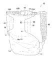
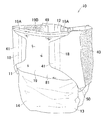
図1〜図3を参照すると、本実施形態に係る開放型の使い捨ておむつ10は、縦方向Yとそれに直交する横方向Xと、縦軸P及び横軸Qとを有する。おむつ10は、肌対向面及び非肌対向面と、前ウエスト域11と、後ウエスト域12と、前後ウエスト域11,12間を縦方向Yへ延びるクロッチ域13とを有するシャーシ14と、少なくともクロッチ域13の肌対向面に取り付けられた吸液構造体15と、シャーシ14の後ウエスト域12における両側縁部から横方向Xの外側へ延出する第1及び第2弾性ベルト片16,17とを含む。
<First Embodiment>
Referring to FIGS. 1 to 3, an open-type
おむつ10は、第1及び第2弾性ベルト片16,17の外側部の肌対向面側に位置するファスナ部18と、前ウエスト域11の非肌対向面側に位置する受止部(ターゲット部)19とから構成されるファスニング手段をさらに有する。ファスナ部18と受止部19を止着することによって、ウエスト開口49及び一対のレッグ開口とが画定される。受止部19は、繊維不織布シートから形成された前ウエスト域11の外面の一部であって、第1実施形態に関する各図において、仮想線で示されている。受止部19は、説明の便宜上、前ウエスト域11の外面の一部を矩形状に区画したものであるが、ファスナ部18が止着することができ、かつ、後記の効果を奏する限りにおいて、各種公知の外形状を有するものであってもよい。
The
シャーシ14は、縦長の略矩形状であって、その外形を形成するカバーシート20を有する。カバーシート20は、不透液性の繊維不織布シート、プラスチックフィルム又はそれらのラミネートシートから形成された内外面シート22,23を有する。内外面シート22,23は、両シート22,23のうちのいずれか一方のシートの内面に塗布されたホットメルト接着剤(図示せず)を介して互いに接合される。カバーシート20の両側部は、内方へ折り曲げられて、クロッチ域13において縦方向Yへ延びる一対のサイド弾性部25が形成される。サイド弾性部25は、内側縁25aと、カバーシート20の折曲部位からなる外側縁25bとを有する。
The
各サイド弾性部25には、縦方向Yへ延びる複数条のストランド状又はストリング状の第1及び第2レッグ弾性体26,27が配設されており、少なくとも縦方向Yにおいて弾性化されている。第1レッグ弾性体26はサイド弾性部25の内側縁25aに沿って縦方向Yへ直状に延びる。第2レッグ弾性体27は、第1レッグ弾性体26の横方向Xの外側に位置し、横軸Qから前ウエスト域11側へ延びる直状部29と、横軸Qから後ウエスト域12側へ延びる曲状部30とを有する。曲状部30は、後方に向かうにつれて次第に横方向Xの外側に延びる。第1及び第2レッグ弾性体26,27は、それらの全周に塗布されたホットメルト接着剤又は/および内外面シート22,23のいずれか一方の内面に塗布されたホットメルト接着剤を介して縦方向Yに伸縮可能な状態で両シート22,23間に固定される。
Each side
各弾性ベルト片16,17は、縦方向Yにおいて離間対向する両端縁32,33と、横方向Xにおいて離間対向する内外側縁34,35とを有する。内側縁34は縦方向Yへ延びる直状を有し、外側縁35は横方向の外方へ向かって凸となる形状を有する。各弾性ベルト片16,17の内側縁34は、後記のとおり、サイド弾性部25の外側縁25bに沿って縦方向Yへ延びる接合域36を介してシャーシ14に接合される。各弾性ベルト片16,17は、横方向Xに伸縮可能な第1弾性部40と、第1弾性部40から横方向Xの外側に位置するフラップ部41とをさらに有する。
Each
第1弾性部40は、繊維不織布又はプラスチックシートから形成された、肌対向面側に位置する第1シート42と、非肌対向面側に位置する第2シート43と、横方向Xへ延びる複数条のストランド状又はストリング状の第1ウエスト弾性体44とを有する。第1ウエスト弾性体44は、第1ウエスト弾性体44の全周に塗布されたホットメルト接着剤又は/及び第1及び第2シート42,43のいずれか一方の内面に塗布されたホットメルト接着剤を介して横方向Xに伸縮可能な状態で両シート42,43間に固定される。フラップ部41は、略台形状の補強シート45から形成される。補強シート45は、例えば、繊維不織布又はプラスチックシートから形成された2枚のシートから形成される。両シートは、それぞれ、第1シート42と第2シート43とに接着又は溶着によって接合されており、第1弾性部40の外側部が補強シート45間に介在された状態で固定される。
The 1st
ファスナ部18は、補強シート45の肌対向面に位置し、プラスチックフィルム、繊維不織布、それらのラミネート等の比較的に剛性及び引張強度の高いシート材料から形成され、メカニカルファスナのフック群を有する。ファスナ部18は、受止部19を形成する前ウエスト域11の外面がプラスチックフィルムによって形成されている場合等において、フック要素群に替えて接着剤を塗布して形成してもよく、その場合には、ファスナ部18を保護するために、その表面にシリコンを塗布したセパレータで被覆してもよい。また、ファスナ部18として、フック群又は接着剤を塗布したテープファスナを後ウエスト域12の両側縁部に直接取り付けてもよい。
The
前後ウエスト域11,12のサイド弾性部25間において、前後連結パネル51,52が吸液構造体15を跨ぐように内側縁25a近傍に取り付けられる。前後連結パネル51,52は、質量約5〜15g/m2の不透液性のSMS(スパンボンド・メルトブローン・スパンボンド)繊維不織布若しくはスパンボンド不織布から形成された内面シート53と、透湿性プラスチックシートから形成された外面シート54とを有する。
Between the side
後ウエスト域12に位置する後連結パネル52は、内外面シート53,54間に介在された複数条のストランド状又はストリング状の第2ウエスト弾性体55をさらに有する。第2ウエスト弾性体55は、第2ウエスト弾性体55の全周に塗布されたホットメルト接着剤又は/及び内外面シート53,54のいずれか一方の内面に塗布されたホットメルト接着剤を介して横方向Xに伸縮可能な状態で両シート53,54間に固定される。連結パネル52は、第2ウエスト弾性体55の配置された領域において、少なくとも横方向Xにおいて弾性化された第2弾性部56を有する。
The
第1及び第2レッグ弾性体26,27は、太さ470〜940dtex、伸長倍率約2.0〜2.8倍、第1ウエスト弾性体44は、太さ約470〜940dtex、伸長倍率約2.5〜3.0倍、第2ウエスト弾性体55は、太さ約470〜940dtex、伸長倍率約2.0〜2.5倍のストランド状又はストリング状の弾性材料からそれぞれ形成することができる。おむつ10が縦方向Y及び横方向Xに伸展された状態において、第1ウエスト弾性体44の横方向Xの寸法、すなわち、第1弾性部40の横方向Xの寸法は、第2ウエスト弾性体55の横方向Xの寸法、すなわち、第2弾性部56の横方向Xの寸法よりも大きくなっている。具体的には、前者が約190〜230mm、後者が約120〜160mmである。このように、第1弾性部40の横方向Xの寸法が第2弾性部56の横方向Xの寸法よりも大きいことによって、着用者のウエスト周りに対するフィット性が向上し、着用時におけるクロッチ域の位置ずれを防止することができる。
The first and second leg
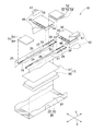
吸液構造体15は、ホットメルト接着剤を介してカバーシート20の主体部の肌対向面に固定されており、吸液層60と、透液性シートから形成された吸液層60の少なくとも肌対向面側を被覆する身体側ライナ61とを有する。吸液層60は、不水溶性かつ自己質量の10倍以上の吸水力を有するいわゆる高吸収性ポリマー粒子(SAP)、木材フラッフパルプ、オプションとして熱可塑性繊維を僅かに含む混合物から形成された吸収性コアを親水性SMS不織布などの透液性シートで被包することによって形成される。
The
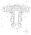
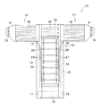
図4及び5を参照すると、カバーシート20は、その展開状態において、横方向Xへ互いに並行して直状に延びる両端縁20a,20bと、縦方向Yへ互いに並行して直状に延びる両側縁20c,20dとによって画定された矩形状であって、吸液構造体15が配置される主体部65(シャーシ14の主体部)と、縦方向Yに延びる一対の折曲ライン67と、折曲ライン67の横方向Xの外側に位置する両側部66とを有する。カバーシート20の両側部66の内面には、両側縁20c,20d間において両端縁20a,20bに沿って横方向Xに一連に延びるホットメルト接着剤を塗布してなる前後端接合域68,69が配置されており、折曲ライン67に沿って両側部66を主体部65に向かって折り曲げ、前後端接合域68,69を介して互いに固定することによって、サイド弾性部25が形成される。図4を参照すると、サイド弾性部25の前後固定端部70,71は、それぞれ、前後端接合域68,69を介して主体部65に固定され、前後固定端部70,71間に位置する中間部72は主体部65に固定されていない。このように、中間部72全体が主体部65に固定されていないことから、おむつ10の着用状態において、前後固定端部70,71間において比較的に高さ寸法の大きなバリアカフが形成される。
Referring to FIGS. 4 and 5, the
図6及び7を参照すると、前連結パネル51は、その中央部がサイド弾性部25の前固定端部70間に位置する前端接合域68を介してシャーシ14に接合され、かつ、その両側部がサイド弾性部25の内側縁25aに沿って縦方向Yへ延びるサイド接合域74を介してシャーシ14に接合される。前端接合域68の縦方向Yの寸法はサイド接合域74の縦方向Yの寸法よりも小さく、前端接合域68とサイド接合域74との間には前連結パネル51が主体部65に固定されていない非固定域75が画定される。図7に示すとおり、かかる非固定域75が画定されることによって、主体部65と前連結パネル51との間には、排泄物を収容するための前中央スペース76が形成される。
Referring to FIGS. 6 and 7, the
図6,8及び9を参照すると、後ウエスト域12において、第1及び第2弾性ベルト片16,17は、サイド弾性部25の外側縁25bに沿って縦方向Yに延びる接合域36を介してシャーシ14に固定される。また、後連結パネル52は、その中央部がサイド弾性部25の後固定端部71間に位置する後端接合域69を介してシャーシ14に接合され、かつ、その両側部がサイド弾性部25の内側縁25aに沿って縦方向Yへ延びるサイド接合域77を介してシャーシ14に接合される。後端接合域69の縦方向Yの寸法はサイド接合域77の縦方向Yの寸法よりも小さく、後端接合域69とサイド接合域77との間には後連結パネル52が主体部65に固定されていない非固定域78が画定される。図9に示すとおり、かかる非固定域78が画定されることによって、主体部65及び吸液構造体15の後端部と後連結パネル52との間には排泄物を収容するための後中央スペース79が形成される。
Referring to FIGS. 6, 8, and 9, in the
図1,6及び11を参照すると、前ウエスト域11の外面の一部から形成される受止部19は、少なくともサイド弾性部25の前固定端部70上に位置するものであって、サイド弾性部25の前固定端部70上に位置する第1区域19Aと、第1区域19A間に位置する第2区域19Bとに区分される。
Referring to FIGS. 1, 6 and 11, the receiving
受止部19にファスナ部18が安定的に止着されるためには、受止部19がよれたりせずに平面性を維持できる程度の所要の剛性を有することが必要なところ、カバーシート20自体に比較的に剛性の高いシート材料を使用した場合には、おむつ10全体の柔軟性が低下するおれがある。本実施形態の場合には、受止部19は、シャーシ14の主体部65に固定されたサイド弾性部25の前固定端部70上であって、複数のシート部材が重なり合って固定された領域、すなわち、厚さ方向Zにおいて内外面シート22,23から構成された4枚のシート部材が積層された比較的に高剛性の領域上に位置する第1区域19Aを有することから、該第1区域19Aにおいて安定的にファスナ部18を止着することができる。受止部19のうち、特に、前連結パネル51がサイド接合域74を介してサイド弾性部25に接合されている領域においては、6枚のシート部材が厚さ方向Zにおいて積層されているので、ファスナ部18をより安定的に止着することができる。
ここで、本明細書における「受止部19の平面性」とは、ファスナ部18が安定的に受止部19に止着され、ファスナ手段が所要の止着強度を発揮しうる程度に受止部19の外面が平らであることを意味する。
In order for the
Here, “the flatness of the receiving
受止部19の第2区域19Bは、サイド弾性部25が位置していないが、カバーシート20と前連結パネル51とが前端接合域68を介して接合されているから、単一のシート部材のみから形成されている場合に比して剛性が高く、安定的にファスナ部18を受止部19に止着することができる。
Although the side
また、前ウエスト域11にウエスト弾性体が配置されている場合には、その収縮作用によって受止部19が変形してその平面性が損なわれるおそれがあるところ、本実施形態においては、ファスナ部18の配置された第1及び第2弾性ベルト片16,17の伸縮作用によって前後ウエスト域11,12を着用者の身体にフィットさせることができる。したがって、受止部19の配置された前ウエスト域11には弾性部材は配置されておらず、受止部19がウエスト弾性体の収縮作用によって変形したりするおそれはない。
Moreover, when the waist elastic body is arrange | positioned in the
例えば、第1及び第2レッグ弾性体26,27が受止部19と同一平面上に位置する場合には、その収縮力が受止部19に直接作用して、その表面が凹凸形状となり、凹状部位においてファスニング要素が受止部19を形成する繊維に係止されず、ファスナ部18と受止部19との止着面積が減少し、所要の止着強度を発揮することができないおそれがある。本実施形態におけるサイド弾性部25は、カバーシート20の両側部66を折り曲げて形成したものであるから、受止部19が配置されたシャーシ14の主体部65とは同一の平面上に位置していない。したがって、第1及び第2レッグ弾性体26,27の収縮力が受止部19に直接作用されることはなく、その収縮作用によって受止部19がよれたり変形したりしてファスナ部18の止着が妨げられるおそれはない。
For example, when the first and second leg
図6を参照すると、サイド弾性部25の第1及び第2レッグ弾性体26,27の前端部26a,27aは受止部19と重なる位置まで延在していない。したがって、第1及び第2レッグ弾性体26,27の収縮力が間接的に作用されることもなく、受止部19がクロッチ域13側に引っ張られてよれたり変形したりするおそれはない。具体的には、第1及び第2レッグ弾性体26,27と受止部19の内端縁19aとの縦方向Yにおける離間寸法Rは約10〜50mmである。離間寸法が10mm以下の場合には、第1及び第2レッグ弾性体26,27の前端26a,27aが受止部19に近接してその収縮力が間接的に作用するおそれがあり、離間寸法が50mm以上の場合には、クロッチ域13の前ウエスト域11側におけるフィット性が低下し、排泄物の横漏れを生じるおそれがある。
Referring to FIG. 6, the
かかる効果を奏するためには、第1及び第2レッグ弾性体26,27のうちの実質的に伸縮性を発現しない部分が受止部19に延在している場合であっても、それらの「伸縮機能(有効)部分」が受止部19と重なる位置に延在していなければよい。「伸縮機能部分」とは、第1及び第2レッグ弾性体26,27のうち伸縮作用が発揮される部分を意味し、実質的に伸縮性を発揮しない、スナップバック(弾性部材のうちシートに固着されていない非固着部分が、自らの収縮によりシートに固着されている接合端部近傍まで戻ること)した部分を含まないものである。したがって、受止部19に第1及び第2レッグ弾性体26,27のうちのカバーシート20に固着されていないスナップバックした部分が延在していたとしても、受止部19に第1及び第2レッグ弾性体26,27による収縮力が作用して変形等するおそれはないので、上記本発明における効果を奏し得るものといえる。
In order to achieve such an effect, even if portions of the first and second leg
本実施形態において、受止部19の横方向Xの寸法は、サイド弾性部25の内側縁25aどうしの横方向Xにおける離間寸法よりも大きく、受止部19の横方向Xにおいて互いに対向する両側縁は、最も横方向Xの外側に位置する第2レッグ弾性体27の前端部27aよりも横方向Xの外側に位置している。したがって、受止部19のファスナ部18との係合面積は広く、止着操作が容易である。また、このように、受止部19を比較的に広く形成しても、第1及び第2レッグ弾性体26,27が第1及び第2弾性ベルト片16,17と連動してクロッチ域13の後方側を引き上げるために後方において外側に曲状に延びる形状である一方、前方においては、直状に延び、かつ、それらの前端部26a,27aが受止部19に延在していないので、第1及び第2レッグ弾性体26,27の収縮によって受止部19のうち、特に、第1区域19Aの平面性が損なわれるおそれはない。
In the present embodiment, the dimension in the lateral direction X of the receiving
さらに、吸液構造体15の前端縁15aは、受止部19の内端縁19aと縦方向Yにおいて離間しており、吸液構造体15は受止部19と重なる位置に配置されておらず、受止部19に吸液構造体15による段差が形成され受止部19が変形したりするおそれがあるところ、かかる事態が生じるおそれはない。一方、後記のとおり、吸液層60が吸液性ポリマー粒子のみから形成され、吸液構造体15が比較的に薄い場合には、図示していないが、吸液構造体15の前端部15aが受止部19の一部と重なって位置することが好ましい。かかる場合には、受止部19にそれを変形させるような段差が形成されることはなく、受止部19の剛性が向上することによってその平面性が維持されるからである。
Further, the
以上のように、本実施形態においては、前ウエスト域11に弾性部材を配置せず、サイド弾性部25の構成態様や第1及び第2レッグ弾性体26,27及び吸液構造体15の配置態様等を適宜設計することによって、受止部19が変形することなく、ファスナ部18を安定的に止着できる程度の平面性が維持されるので、ファスナ手段は所要の係合強度を奏することができる。
As described above, in the present embodiment, the elastic member is not disposed in the
<第2実施形態>
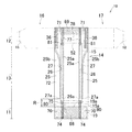
図12及び13を参照すると、本実施形態において、受止部19は、前ウエスト域11を形成するシャーシ14の外面に配置された、プラスチックフィルムや繊維不織布等から形成された基材シート81と、基材シート81に繊維不織布や編み物等を貼り付して形成された、メカニカルファスナのループ群とを有する。
Second Embodiment
Referring to FIGS. 12 and 13, in the present embodiment, the receiving
基材シート81は、前ウエスト域11のほぼ全体に位置しており、受止部19は、第1区域19Aがサイド弾性部25の前固定端部70上に位置する基材シート81から形成されるので、第1実施形態よりもさらに高い剛性を有し、平面性及び保形性に優れ、より安定的にファスナ部18を止着することができる。また、既述のとおり、第1実施形態における前ウエスト域11の外面から形成される第1及び第2区域19A,19Bは、シート部材が積層されて比較的に高剛性の領域であるから、基材シート81をその平面性が維持されるように皺が寄らない状態で安定的に取り付けることができる。さらに、基材シート81が前ウエスト域11の全体に位置することによって前ウエスト域11全体の剛性が比較的に高くなるので、肌当たりの弱い幼児の臍近傍を保護することができ、また、立位状態の着用者におむつ10を着用させるときに、前ウエスト域11の一方側部から手を離したまま着用操作を行ったとしても、前ウエスト域11がよれて垂れさがったりすることはなく、着用操作が容易である。
The
<第3実施形態>
図14及び15を参照すると、本実施形態においては、吸液構造体15の吸液層60は、主として高吸収性ポリマー粒子から形成された吸収性コアと、肌対向面側に位置する質量約8.0〜15.0g/m2、好ましくは、質量約10.0g/m2の透液性の繊維不織布から形成された第1シート(上面シート)91と、非肌対向面側に位置する質量約8.0〜15.0g/m2、好ましくは、11.0g/m2の透液性又は難透液性あるいは不透液性のSMS繊維不織布から形成された第2シート(下面シート)92とを含む。
<Third Embodiment>
14 and 15, in the present embodiment, the
吸液層60は、さらに、吸収性コアが配置された、縦方向Yへ所与寸法離間する略矩形状に画定された吸液域93と、吸収性コアが実質的に配置されていない、吸液域を取り囲むように形成されたシール部94とを有する。なお、本実施形態において、吸液域93は、8つの区域に区分されているが、吸液構造体15の要する吸収性能に応じてその面積、区域数を適宜変更することができ、例えば、8つ以上の区域に区分されていてもよいし、吸液構造体15の全体に延びる1つの区域のみから形成されていてもよい。
The liquid-absorbing
吸液域93では、第1シート91の内面には、ホットメルト接着剤96を介して質量約30〜300g/m2、好ましくは、質量約40〜280g/m2の高吸収性ポリマー粒子95がほぼ一様に固定されている。高吸収性ポリマー粒子95には、吸液層60全体の吸収速度を調整するために、例えば、吸収速度の異なる2種類のものを併用することができる。また、後記の本発明の効果を奏する限りにおいて、吸収性コアには、高吸収性ポリマー粒子95のみならずフラッフパルプやオプションとして熱可塑性繊維などの公知の材料を比較的に低い混合率でその一部に含むものであってもよい。具体的には、フラッフパルプ等の吸水性繊維を混合する場合は、吸収性コア全体に対して約0〜30質量%の割合で混合されていることが好ましい。ホットメルト接着剤96には、各種公知のものを使用することができるが、体液の吸収後であって、吸収性ポリマー粒子が第1シート91から剥離しないようにするために、疎水性を有する接着剤を使用することが好ましい。
In the
このように、吸液層60の吸収性コアは、吸収性ポリマー粒子95とそれを被包するシート部材のみから形成されているので、吸液構造体15は、吸収性コアが吸収性ポリマー粒子95とフラッフパルプとの混合物から形成されている場合に比して薄くなる。したがって、パルプ繊維を比較的に多量に含んで比較的に厚みのある吸液層60を用いた場合には受止部19と重なる前端縁15a近傍において受止部19の一部を変形させるような段差が生じるおそれがあるが、本実施形態においてはかかる段差を生じるおそれはなく、より受止部19の平滑性が維持されうる。
Thus, since the absorptive core of the
おむつ10を構成する各構成部材には、本明細書に記載されている材料のほかに、この種の物品における通常用いられている各種の公知の材料を制限なく用いることができる。また、本発明の明細書及び特許請求の範囲において、「第1」及び「第2」の用語等は、同様の要素、位置を単に区別するために用いられている。
In addition to the materials described in this specification, various known materials that are usually used in this type of article can be used without limitation for the respective members constituting the
以上に記載した本発明に関する開示は、少なくとも下記事項に要約することができる。 The disclosure relating to the present invention described above can be summarized in at least the following matters.
縦方向及び横方向を有し、肌対向面及び非肌対向面と、前ウエスト域と、後ウエスト域と、前記前後ウエスト域間に位置するクロッチ域と、少なくとも前記クロッチ域において前記縦方向へ延びる吸液構造体を有するシャーシと、
前記後ウエスト域において前記シャーシの両側縁から前記横方向の外側へ延び、前記肌対向面にファスナ部が配置された弾性ベルト片を含む開放型の使い捨ておむつにおいて、
前記前ウエスト域の前記非肌対向面には、前記ファスナ部が係止される受止部が位置しており、
前記シャーシは、前記吸液構造体が配置された主体部と、前記主体部の前記横方向の外方に位置する両側部と、前記両側部を内方へ折り曲げて形成された一対のサイド弾性部とを含み、
前記一対のサイド弾性部は、前記シャーシの前後端縁に沿って前記横方向へ延びる前後端接合域を介して前記シャーシの前記主体部に固定された前後固定端部と、前記前後固定端部間において前記縦方向へ延びるレッグ弾性体とを有し、
前記レッグ弾性体のうちの伸縮機能部位は前記受止部まで延在しておらず、
前記前ウエスト域のうちの前記受止部の位置する領域は非弾性であって、
前記前ウエスト域は、前記前端接合域を介して前記シャーシの前記主体部の前端部に接合され、かつ、前記サイド弾性部の内側縁に沿って前記縦方向へ延びるサイド接合域を介して前記サイド弾性部に接合された前連結パネルをさらに有し、
前記受止部が前記前連結パネルの前記接合域及び前記サイド接合域のうちの少なくとも一部と重なって位置する。
Having a longitudinal direction and a transverse direction, a skin-facing side and a non-skin-facing surface, a front waist region, a rear waist region, a crotch region extending between said front and rear waist regions, to the longitudinal direction at least the crotch region A chassis having an extending liquid-absorbing structure;
In an open-type disposable diaper including an elastic belt piece extending from the both side edges of the chassis to the outside in the lateral direction in the rear waist region and having a fastener portion disposed on the skin facing surface,
Wherein the said non-skin-facing surface of the front waist region, the receiving portion of the fastener portion is locked is positioned,
The chassis includes a main body portion on which the liquid absorbing structure is disposed, both side portions located outwardly in the lateral direction of the main body portion, and a pair of side elasticity formed by bending the both side portions inwardly. Including
The pair of side elastic portions includes front and rear fixed end portions fixed to the main body portion of the chassis via front and rear end joint regions extending in the lateral direction along the front and rear end edges of the chassis, and the front and rear fixed end portions. Leg elastic body extending in the longitudinal direction between,
The stretchable functional part of the leg elastic body does not extend to the receiving part,
The region where the receiving portion is located in the front waist region is inelastic,
The front waist region is joined to the front end portion of the main body portion of the chassis via the front end joint region, and the side waist region extends in the longitudinal direction along the inner edge of the side elastic portion. A front connection panel joined to the side elastic portion;
The receiving portion is positioned so as to overlap at least a part of the joining area and the side joining area of the front connection panel.
上記段落0043に開示した本発明は、少なくとも下記の実施の形態を含むことができる。
(1)前記レッグ弾性体は、複数条のストリング状又はストランド状の弾性材料から形成されており、前記サイド弾性部の前記内側縁に沿って前記縦方向へ延びる第1レッグ弾性体と、前記第1弾性体の前記横方向の外側に位置して前記縦方向へ延びる第2弾性体とを有し、前記第2弾性体は、前記前ウエスト域側から後方へ延びる直状部と、前記後ウエスト域側において前記縦方向の外側へ向かうにつれて次第に前記横方向の外側へ延びる曲状部とを有する。
(2)前記受止部の前記横方向の寸法は、前記サイド弾性部の前記内側縁どうしの前記横方向における離間寸法よりも大きく、前記受止部の前記横方向において互いに対向する両側縁は、最も前記横方向の外側に位置する前記レッグ弾性体の前端部よりも前記横方向の外側に位置する。
(3)前記前ウエスト域において、前記シャーシの前記主体部の前端部と前記弾性サイド部の内側縁とに接合された前連結パネルを有し、前記受止部が前記前連結パネルの接合域の少なくとも一部と重なって位置する。
(4)前記受止部は、前記前ウエスト域の前記非肌対向面を形成する繊維不織布シートから形成される。
(5)前記吸液構造体は、透液性の身体側ライナと吸液層とを有し、前記吸液層は、透液性の第1シートと、透液性又は不透液性の第2シートと、前記第1及び第2シート間に介在された吸収性ポリマー粒子とを有する。
(6)前記受止部の内端縁と前記レッグ弾性体の前記前端部との前記縦方向における離間寸法が、10〜50mmである。
The present invention disclosed in the above paragraph 0043 can include at least the following embodiments.
(1) the leg elastic body includes a first leg elastic member extending in the longitudinal direction along the plural rows of strings like or is formed from a strand-like elastic material, the inner edge of the side elastic portion, said A second elastic body that is positioned outside the first elastic body and extends in the longitudinal direction, and the second elastic body includes a straight portion that extends rearward from the front waist region side, and And a curved portion that gradually extends outward in the lateral direction toward the outer side in the longitudinal direction on the rear waist region side.
(2) The lateral dimension of the receiving part is larger than the lateral dimension of the inner edges of the side elastic parts in the lateral direction, and both side edges of the receiving part facing each other in the lateral direction are , Located on the outer side in the lateral direction than the front end portion of the leg elastic body located on the outermost side in the lateral direction.
(3) The front waist region includes a front connection panel joined to a front end portion of the main body portion of the chassis and an inner edge of the elastic side portion, and the receiving portion is a joint region of the front connection panel. It overlaps with at least a part of.
(4) The said receiving part is formed from the fiber nonwoven fabric sheet which forms the said non-skin opposing surface of the said front waist area.
(5) The liquid-absorbing structure includes a liquid-permeable body-side liner and a liquid-absorbing layer, and the liquid-absorbing layer includes a liquid-permeable first sheet and a liquid-permeable or liquid-impermeable material. It has a 2nd sheet | seat and the absorptive polymer particle interposed between the said 1st and 2nd sheet | seat.
(6) spaced distance in the longitudinal direction between the front end of the inner edge of the receiving portion the leg elastics is a 10 ~50mm.
10 開放型の使い捨ておむつ
11 前ウエスト域
12 後ウエスト域
13 クロッチ域
14 シャーシ
15 吸液構造体
16,17 弾性ベルト片
18 ファスナ部
19 受止部
25 サイド弾性部
25a サイド弾性部の内側縁
25b サイド弾性部の外側縁
26 第1レッグ弾性体(レッグ弾性体)
27 第2レッグ弾性体(レッグ弾性体)
29 第2レッグ弾性体の直状部
30 第2レッグ弾性体の曲状部
51 前連結パネル
60 吸液層
65 シャーシの主体部
66 シャーシの両側部
68 前端接合域
69 後端接合域
70 前固定端部
71 後固定端部
81 基材シート
91 第1シート
92 第2シート
93 吸液域
94 シール部
95 吸収性ポリマー粒子
R レッグ弾性体の前端部と受止部の内側縁との縦方向における離間寸法
X 横方向
Y 縦方向
DESCRIPTION OF
27 Second leg elastic body (leg elastic body)
29
Claims (7)
前記後ウエスト域において前記シャーシの両側縁から前記横方向の外側へ延び、前記肌対向面にファスナ部が配置された弾性ベルト片を含む開放型の使い捨ておむつにおいて、
前記前ウエスト域の前記非肌対向面には、前記ファスナ部が係止される受止部が位置しており、
前記シャーシは、前記吸液構造体が配置された主体部と、前記主体部の前記横方向の外方に位置する両側部と、前記両側部を内方へ折り曲げて形成された一対のサイド弾性部とを含み、
前記一対のサイド弾性部は、前記シャーシの前後端縁に沿って前記横方向へ延びる前後端接合域を介して前記シャーシの前記主体部に固定された前後固定端部と、前記前後固定端部間において前記縦方向へ延びるレッグ弾性体とを有し、
前記レッグ弾性体のうちの伸縮機能部位は前記受止部まで延在しておらず、
前記前ウエスト域のうちの前記受止部の位置する領域は非弾性であって、
前記前ウエスト域は、前記前端接合域を介して前記シャーシの前記主体部の前端部に接合され、かつ、前記サイド弾性部の内側縁に沿って前記縦方向へ延びるサイド接合域を介して前記サイド弾性部に接合された前連結パネルをさらに有し、
前記受止部が前記前連結パネルの前記接合域及び前記サイド接合域のうちの少なくとも一部と重なって位置することを特徴とするおむつ。 Having a longitudinal direction and a transverse direction, a skin-facing side and a non-skin-facing surface, a front waist region, a rear waist region, a crotch region extending between said front and rear waist regions, to the longitudinal direction at least the crotch region A chassis having an extending liquid-absorbing structure;
In an open-type disposable diaper including an elastic belt piece extending from the both side edges of the chassis to the outside in the lateral direction in the rear waist region and having a fastener portion disposed on the skin facing surface,
Wherein the said non-skin-facing surface of the front waist region, the receiving portion of the fastener portion is locked is positioned,
The chassis includes a main body portion on which the liquid absorbing structure is disposed, both side portions located outwardly in the lateral direction of the main body portion, and a pair of side elasticity formed by bending the both side portions inwardly. Including
The pair of side elastic portions includes front and rear fixed end portions fixed to the main body portion of the chassis via front and rear end joint regions extending in the lateral direction along the front and rear end edges of the chassis, and the front and rear fixed end portions. Leg elastic body extending in the longitudinal direction between,
The stretchable functional part of the leg elastic body does not extend to the receiving part,
The region where the receiving portion is located in the front waist region is inelastic,
The front waist region is joined to the front end portion of the main body portion of the chassis via the front end joint region, and the side waist region extends in the longitudinal direction along the inner edge of the side elastic portion. A front connection panel joined to the side elastic portion;
The diaper characterized in that the receiving portion is positioned so as to overlap at least a part of the joining area and the side joining area of the front connection panel.
Priority Applications (1)
| Application Number | Priority Date | Filing Date | Title |
|---|---|---|---|
| JP2012238333A JP6099357B2 (en) | 2012-10-29 | 2012-10-29 | Open disposable diaper |
Applications Claiming Priority (1)
| Application Number | Priority Date | Filing Date | Title |
|---|---|---|---|
| JP2012238333A JP6099357B2 (en) | 2012-10-29 | 2012-10-29 | Open disposable diaper |
Publications (3)
| Publication Number | Publication Date |
|---|---|
| JP2014087429A JP2014087429A (en) | 2014-05-15 |
| JP2014087429A5 JP2014087429A5 (en) | 2015-11-05 |
| JP6099357B2 true JP6099357B2 (en) | 2017-03-22 |
Family
ID=50789935
Family Applications (1)
| Application Number | Title | Priority Date | Filing Date |
|---|---|---|---|
| JP2012238333A Active JP6099357B2 (en) | 2012-10-29 | 2012-10-29 | Open disposable diaper |
Country Status (1)
| Country | Link |
|---|---|
| JP (1) | JP6099357B2 (en) |
Families Citing this family (1)
| Publication number | Priority date | Publication date | Assignee | Title |
|---|---|---|---|---|
| EP3549564B1 (en) * | 2016-12-28 | 2020-11-04 | Unicharm Corporation | Absorbent article |
Family Cites Families (3)
| Publication number | Priority date | Publication date | Assignee | Title |
|---|---|---|---|---|
| EP1559387B1 (en) * | 2002-10-24 | 2019-12-18 | Zuiko Corporation | Method for producing a disposable wearing article |
| JP5328590B2 (en) * | 2009-09-30 | 2013-10-30 | ユニ・チャーム株式会社 | Disposable diapers |
| JP5596984B2 (en) * | 2010-01-08 | 2014-10-01 | ユニ・チャーム株式会社 | Disposable wearing items |
-
2012
- 2012-10-29 JP JP2012238333A patent/JP6099357B2/en active Active
Also Published As
| Publication number | Publication date |
|---|---|
| JP2014087429A (en) | 2014-05-15 |
Similar Documents
| Publication | Publication Date | Title |
|---|---|---|
| JP6021447B2 (en) | Open disposable diaper | |
| JP5968117B2 (en) | Disposable wearing items | |
| JP5457822B2 (en) | Disposable wearing items | |
| JP2007202575A (en) | Absorbing laminated body and disposable absorbing article | |
| JP2007202576A (en) | Absorbent laminate and disposable absorbent article | |
| JP5761949B2 (en) | Disposable wearing items | |
| WO2012060366A1 (en) | Disposable diaper | |
| JP5734161B2 (en) | Disposable wearing items | |
| JP4823956B2 (en) | Absorbent article manufacturing method and absorbent article | |
| WO2016170693A1 (en) | Absorbent article | |
| JP5907603B2 (en) | Disposable wearing items | |
| TWI667017B (en) | Absorbent article | |
| JP6274977B2 (en) | Disposable wearing items | |
| JP6352088B2 (en) | Disposable wear | |
| JP6173219B2 (en) | Disposable wearing items | |
| JP6008592B2 (en) | Disposable diapers | |
| JP6099357B2 (en) | Open disposable diaper | |
| JP6172908B2 (en) | Open disposable diaper | |
| JP6164083B2 (en) | Disposable diapers | |
| JP2017217257A (en) | Absorbent article | |
| JP6636848B2 (en) | Absorbent articles | |
| JP6033040B2 (en) | Open disposable diaper | |
| JP6654864B2 (en) | Disposable diapers | |
| JP5933251B2 (en) | Disposable wearing items | |
| JP6091147B2 (en) | Open disposable diaper |
Legal Events
| Date | Code | Title | Description |
|---|---|---|---|
| A521 | Request for written amendment filed |
Free format text: JAPANESE INTERMEDIATE CODE: A523 Effective date: 20150916 |
|
| A621 | Written request for application examination |
Free format text: JAPANESE INTERMEDIATE CODE: A621 Effective date: 20150916 |
|
| A977 | Report on retrieval |
Free format text: JAPANESE INTERMEDIATE CODE: A971007 Effective date: 20160708 |
|
| A131 | Notification of reasons for refusal |
Free format text: JAPANESE INTERMEDIATE CODE: A131 Effective date: 20160719 |
|
| A521 | Request for written amendment filed |
Free format text: JAPANESE INTERMEDIATE CODE: A523 Effective date: 20160905 |
|
| TRDD | Decision of grant or rejection written | ||
| A01 | Written decision to grant a patent or to grant a registration (utility model) |
Free format text: JAPANESE INTERMEDIATE CODE: A01 Effective date: 20170124 |
|
| A61 | First payment of annual fees (during grant procedure) |
Free format text: JAPANESE INTERMEDIATE CODE: A61 Effective date: 20170221 |
|
| R150 | Certificate of patent or registration of utility model |
Ref document number: 6099357 Country of ref document: JP Free format text: JAPANESE INTERMEDIATE CODE: R150 |
|
| R250 | Receipt of annual fees |
Free format text: JAPANESE INTERMEDIATE CODE: R250 |
|
| R250 | Receipt of annual fees |
Free format text: JAPANESE INTERMEDIATE CODE: R250 |
|
| R250 | Receipt of annual fees |
Free format text: JAPANESE INTERMEDIATE CODE: R250 |
|
| R250 | Receipt of annual fees |
Free format text: JAPANESE INTERMEDIATE CODE: R250 |
|
| R250 | Receipt of annual fees |
Free format text: JAPANESE INTERMEDIATE CODE: R250 |