JP6098117B2 - Portable tools - Google Patents
Portable tools Download PDFInfo
- Publication number
- JP6098117B2 JP6098117B2 JP2012239785A JP2012239785A JP6098117B2 JP 6098117 B2 JP6098117 B2 JP 6098117B2 JP 2012239785 A JP2012239785 A JP 2012239785A JP 2012239785 A JP2012239785 A JP 2012239785A JP 6098117 B2 JP6098117 B2 JP 6098117B2
- Authority
- JP
- Japan
- Prior art keywords
- drive information
- operation switch
- power source
- switch unit
- unit
- Prior art date
- Legal status (The legal status is an assumption and is not a legal conclusion. Google has not performed a legal analysis and makes no representation as to the accuracy of the status listed.)
- Active
Links
Images


Classifications
-
- B—PERFORMING OPERATIONS; TRANSPORTING
- B25—HAND TOOLS; PORTABLE POWER-DRIVEN TOOLS; MANIPULATORS
- B25F—COMBINATION OR MULTI-PURPOSE TOOLS NOT OTHERWISE PROVIDED FOR; DETAILS OR COMPONENTS OF PORTABLE POWER-DRIVEN TOOLS NOT PARTICULARLY RELATED TO THE OPERATIONS PERFORMED AND NOT OTHERWISE PROVIDED FOR
- B25F5/00—Details or components of portable power-driven tools not particularly related to the operations performed and not otherwise provided for
- B25F5/02—Construction of casings, bodies or handles
-
- B—PERFORMING OPERATIONS; TRANSPORTING
- B24—GRINDING; POLISHING
- B24B—MACHINES, DEVICES, OR PROCESSES FOR GRINDING OR POLISHING; DRESSING OR CONDITIONING OF ABRADING SURFACES; FEEDING OF GRINDING, POLISHING, OR LAPPING AGENTS
- B24B23/00—Portable grinding machines, e.g. hand-guided; Accessories therefor
- B24B23/005—Auxiliary devices used in connection with portable grinding machines, e.g. holders
-
- B—PERFORMING OPERATIONS; TRANSPORTING
- B25—HAND TOOLS; PORTABLE POWER-DRIVEN TOOLS; MANIPULATORS
- B25F—COMBINATION OR MULTI-PURPOSE TOOLS NOT OTHERWISE PROVIDED FOR; DETAILS OR COMPONENTS OF PORTABLE POWER-DRIVEN TOOLS NOT PARTICULARLY RELATED TO THE OPERATIONS PERFORMED AND NOT OTHERWISE PROVIDED FOR
- B25F5/00—Details or components of portable power-driven tools not particularly related to the operations performed and not otherwise provided for
- B25F5/001—Gearings, speed selectors, clutches or the like specially adapted for rotary tools
-
- B—PERFORMING OPERATIONS; TRANSPORTING
- B26—HAND CUTTING TOOLS; CUTTING; SEVERING
- B26B—HAND-HELD CUTTING TOOLS NOT OTHERWISE PROVIDED FOR
- B26B21/00—Razors of the open or knife type; Safety razors or other shaving implements of the planing type; Hair-trimming devices involving a razor-blade; Equipment therefor
- B26B21/40—Details or accessories
- B26B21/405—Electric features; Charging; Computing devices
- B26B21/4056—Sensors or controlling means
-
- A—HUMAN NECESSITIES
- A01—AGRICULTURE; FORESTRY; ANIMAL HUSBANDRY; HUNTING; TRAPPING; FISHING
- A01G—HORTICULTURE; CULTIVATION OF VEGETABLES, FLOWERS, RICE, FRUIT, VINES, HOPS OR SEAWEED; FORESTRY; WATERING
- A01G3/00—Cutting implements specially adapted for horticultural purposes; Delimbing standing trees
- A01G3/04—Apparatus for trimming hedges, e.g. hedge shears
- A01G3/047—Apparatus for trimming hedges, e.g. hedge shears portable
- A01G3/053—Apparatus for trimming hedges, e.g. hedge shears portable motor-driven
-
- A—HUMAN NECESSITIES
- A01—AGRICULTURE; FORESTRY; ANIMAL HUSBANDRY; HUNTING; TRAPPING; FISHING
- A01G—HORTICULTURE; CULTIVATION OF VEGETABLES, FLOWERS, RICE, FRUIT, VINES, HOPS OR SEAWEED; FORESTRY; WATERING
- A01G3/00—Cutting implements specially adapted for horticultural purposes; Delimbing standing trees
- A01G3/06—Hand-held edge trimmers or shears for lawns
-
- H—ELECTRICITY
- H01—ELECTRIC ELEMENTS
- H01H—ELECTRIC SWITCHES; RELAYS; SELECTORS; EMERGENCY PROTECTIVE DEVICES
- H01H9/00—Details of switching devices, not covered by groups H01H1/00 - H01H7/00
- H01H9/02—Bases, casings, or covers
- H01H9/06—Casing of switch constituted by a handle serving a purpose other than the actuation of the switch, e.g. by the handle of a vacuum cleaner
Landscapes
- Engineering & Computer Science (AREA)
- Mechanical Engineering (AREA)
- Life Sciences & Earth Sciences (AREA)
- Forests & Forestry (AREA)
- Biodiversity & Conservation Biology (AREA)
- Ecology (AREA)
- Environmental Sciences (AREA)
- Portable Power Tools In General (AREA)
- Harvester Elements (AREA)
Description
本発明は、刈込機等のように先端工具を電動モータ等の駆動源により駆動するようにした携帯用工具における駆動情報を表示する操作表示装置を備えた携帯用工具に関する。 The present invention relates to a portable tool including an operation display device that displays driving information in a portable tool in which a tip tool is driven by a driving source such as an electric motor such as a trimming machine.
電動モータ等を動力源として先端工具を駆動するようにした携帯用工具には、刈込機、丸鋸、ドライバ、インパクトドライバ、ハンマ、ハンマドリル、ジグソー、グラインダ、ブロワ等がある。刈込機は、一対のブレードを先端工具として植え込みや生垣の枝葉等の樹木の剪定作業に使用されヘッジトリマとも言われる。丸鋸は、円板形状の鋸刃を先端工具としてワークの切断や溝切り作業に使用される。ドライバは、ドライバビットを先端工具としてボルトやナットのねじ部材を回転するために使用され、先端工具に衝撃力を加えるようにしたタイプはインパクトドライバ、インパクトレンチまたはハンマドリルと言われる。ジグソーは、往復動する鋸刃を先端工具として被加工物を曲線切りや直切り等の加工を行うために使用される。グラインダは砥石を先端工具としてワークの研磨作業や研削作業に使用される。ブロワはノズルから風を排出して枯葉等を集める作業に使用される。 Examples of portable tools that use an electric motor or the like as a power source to drive a tip tool include a trimming machine, a circular saw, a driver, an impact driver, a hammer, a hammer drill, a jigsaw, a grinder, and a blower. The trimming machine is also used as a hedge trimmer for planting trees and pruning trees such as hedge branches and leaves using a pair of blades as a tip tool. Circular saws are used for work cutting and grooving operations using a disk-shaped saw blade as a tip tool. A driver is used to rotate a screw member such as a bolt or a nut using a driver bit as a tip tool, and a type that applies an impact force to the tip tool is called an impact driver, an impact wrench, or a hammer drill. Jigsaws are used for performing cutting such as curving and straight cutting on a workpiece using a reciprocating saw blade as a tip tool. A grinder is used for polishing and grinding work with a grindstone as a tip tool. The blower is used for collecting dead leaves and the like by discharging wind from the nozzle.
電動モータを駆動源とし電動モータに電力を供給するための電池パックを有する携帯用工具には、電池パックの残存容量等の駆動情報を表示するための操作表示パネルが設けられている。電池パックの残存容量のみならず、先端工具の速度に対応した電動モータの速度等を駆動情報として操作表示部に表示する場合には、電池パックの残存容量を容量表示部に点灯表示させる際に操作されるスイッチと、他の情報を点灯表示させる際に操作されるスイッチとが操作表示パネルに別々に設けられている。 A portable tool having a battery pack for supplying electric power to an electric motor using an electric motor as a driving source is provided with an operation display panel for displaying driving information such as a remaining capacity of the battery pack. When displaying not only the remaining capacity of the battery pack but also the speed of the electric motor corresponding to the speed of the tip tool on the operation display section as drive information, when the remaining capacity of the battery pack is displayed on the capacity display section A switch to be operated and a switch to be operated when other information is turned on are separately provided on the operation display panel.
特許文献1には、電池パックから供給される電力により先端工具を駆動するようにした丸鋸、ハンマドリルおよびジグソー等の携帯用工具が記載されている。丸鋸の操作表示パネル部には、電池パックの残存容量を容量表示部に点灯表示させる際に操作されるスイッチと、電動モータのブラシの寿命を寿命表示部に点灯表示させる際に操作されるスイッチとがそれぞれ分離して別々に設けられている。
上述のように、携帯用工具の操作表示パネル部に、相互に異なった機能を表示させるために複数のスイッチを分離して設けるようにすると、操作表示パネル部を大きくしなければならなくなる。さらに、相互に異なった機能を表示させるための複数の表示部を操作表示パネル部に分離して設けると、操作表示パネル部を大きくしなければならなくなる。 As described above, if a plurality of switches are separately provided on the operation display panel unit of the portable tool in order to display different functions, the operation display panel unit must be enlarged. Furthermore, if a plurality of display units for displaying different functions are provided separately in the operation display panel unit, the operation display panel unit must be enlarged.
操作表示パネル部が大きくなると、作業者は特定の機能を表示するために、大きな操作パネル部に設けられた複数のスイッチのうち、特定のスイッチを選択して操作する必要があり、操作性が悪いという課題がある。さらに、大きな操作表示パネル部が取り付けられる制御基板も大きくしなければならず、部品点数が増加して携帯用工具が大型化し、製造コストも高くなる。 When the operation display panel is enlarged, an operator needs to select and operate a specific switch among a plurality of switches provided on the large operation panel in order to display a specific function. There is a problem of being bad. Furthermore, the control board to which the large operation display panel unit is attached must be enlarged, the number of parts increases, the portable tool becomes larger, and the manufacturing cost increases.
本発明の目的は、携帯用工具の操作性を向上することにある。 An object of the present invention is to improve the operability of a portable tool.
本発明の携帯用工具は、作業者が把持するハンドル部と、該ハンドル部の前方に位置し動力源を収容する動力源収容部とを備えたケーシングと、該動力源収容部より前方に位置し前記動力源により駆動される先端工具と、を有する携帯用工具であって、少なくとも前記動力源の設定速度と前記動力源としての電動モータに電力を供給する電池の残量とを含む駆動情報を表示する駆動情報表示部及び前記駆動情報表示部に表示される駆動情報を選択する操作スイッチ部が設けられた操作表示パネル部を有し、前記操作表示パネル部を前記ケーシングの上下方向における頂部を結ぶ仮想線よりも凹んだ位置に配置し、単一の前記操作スイッチ部の操作により前記駆動情報表示部の表示が前記動力源の設定速度と前記電池の残量とで切り換えられ、前記操作スイッチ部により前記設定速度の設定を変更可能とし、単一の前記操作スイッチ部の操作態様により前記駆動情報表示部による駆動情報の表示内容の切り換えと前記設定速度の設定の変更の何れかが選択されて行われることを特徴とする。 A portable tool according to the present invention includes a casing having a handle portion gripped by an operator, a power source storage portion positioned in front of the handle portion and storing a power source, and positioned in front of the power source storage portion. Driving information including at least a set speed of the power source and a remaining amount of a battery that supplies electric power to the electric motor as the power source. And an operation display panel unit provided with an operation switch unit for selecting drive information displayed on the drive information display unit, and the operation display panel unit is a top portion in the vertical direction of the casing. disposed at a position recessed from the imaginary line connecting the display of the driver information display unit by the operation of a single of the operation switch section is switched in the remaining capacity of the battery and setting speed of the power source, The setting of the setting speed can be changed by the operation switch unit, and either the switching of the display information of the driving information by the driving information display unit or the change of the setting of the setting speed by the operation mode of the single operation switch unit Is selected and performed .
本発明の携帯用工具は、前記駆動情報表示部は、前記操作スイッチ部の操作により前記動力源の設定速度から前記電池の残量の表示に切り換えられた後、前記操作スイッチ部の操作がオフされることで前記動力源の駆動速度の表示に戻されることを特徴とする。本発明の携帯用工具は、前記操作表示パネル部を前記ハンドル部より前方の前記ケーシングの上面に設け、作業者が前記ハンドル部を把持した状態のままで前記操作スイッチ部を操作可能であることを特徴とする。本発明の携帯用工具は、前記ケーシングは前記ハンドル部から前記動力源収容部に向かうに従って上向きに傾斜する前記ハンドル部側を向いた傾斜部を有し、前記操作表示パネル部を前記傾斜部に設けたことを特徴とする。 In the portable tool according to the present invention, after the drive information display unit is switched from the set speed of the power source to the display of the remaining battery level by the operation of the operation switch unit, the operation of the operation switch unit is turned off. Thus, the display returns to the display of the driving speed of the power source . In the portable tool of the present invention, the operation display panel unit is provided on the upper surface of the casing in front of the handle unit, and an operator can operate the operation switch unit while holding the handle unit. It is characterized by. In the portable tool of the present invention, the casing has an inclined portion facing the handle portion side, which is inclined upward as it goes from the handle portion toward the power source accommodating portion, and the operation display panel portion is used as the inclined portion. It is provided.
本発明の携帯用工具は、動力源を収容する動力源収容部および作業者により把持されるハンドルを備えたケーシングを有する携帯用工具であって、少なくとも前記動力源の設定速度と前記動力源としての電動モータに電力を供給する電池の残量とを含む複数の駆動情報のうち特定の駆動情報を表示する駆動情報表示部と、前記複数の駆動情報のうち前記駆動情報表示部に表示される特定の駆動情報を選択する操作スイッチ部とが設けられた操作表示パネル部を設け、単一の前記操作スイッチ部の操作により、前記駆動情報表示部の表示が前記動力源の設定速度と前記電池の残量とで切り換えられ、前記操作スイッチ部により前記設定速度の設定を変更可能とし、単一の前記操作スイッチ部の操作態様により前記駆動情報表示部による駆動情報の表示内容の切り換えと前記設定速度の設定の変更の何れかが選択されて行われることを特徴とする。 A portable tool according to the present invention is a portable tool having a casing having a power source accommodating portion for accommodating a power source and a handle gripped by an operator, and at least as a set speed of the power source and the power source. A drive information display unit that displays specific drive information among a plurality of drive information including a remaining amount of a battery that supplies power to the electric motor, and is displayed on the drive information display unit among the plurality of drive information. An operation display panel unit provided with an operation switch unit for selecting specific drive information is provided, and when the single operation switch unit is operated, the display of the drive information display unit displays the set speed of the power source and the battery of switched between the remaining amount, the operation switch section by a changeable set of the set speed, the driving information by the driver information display section by operating mode of a single of the operation switch unit Wherein the one of the configuration changes of switching between the set speed of the display contents is performed is selected.
本発明の携帯用工具は、前記駆動情報表示部は、前記操作スイッチ部の操作により前記動力源の設定速度から前記電池の残量の表示に切り換えられた後、前記操作スイッチ部の操作がオフされることで前記動力源の駆動速度の表示に戻されることを特徴とする。本発明の携帯用工具は、前記操作スイッチ部の操作時間を前記操作スイッチ部の操作態様として、前記操作時間により前記駆動情報の表示を前記操作スイッチ部により切り換えることを特徴とする。本発明の携帯用工具は、前記操作スイッチ部の操作回数を前記操作スイッチ部の操作態様として、前記操作回数により前記駆動情報の表示を前記操作スイッチ部により切り換えることを特徴とする。本発明の携帯用工具は、前記駆動情報表示部は、前記電池の寿命を表示することを特徴とする。本発明の携帯用工具は、前記駆動情報表示部は、前記電動モータの寿命を表示することを特徴とする。本発明の携帯用工具は、前記駆動情報表示部は、複数の発光部を有し、前記発光部の点灯数により前記駆動情報表示部による駆動情報の表示内容を切り換えることを特徴とする。 In the portable tool according to the present invention, after the drive information display unit is switched from the set speed of the power source to the display of the remaining battery level by the operation of the operation switch unit, the operation of the operation switch unit is turned off. Thus, the display returns to the display of the driving speed of the power source . The portable tool of the present invention is characterized in that an operation time of the operation switch unit is set as an operation mode of the operation switch unit, and the display of the drive information is switched by the operation switch unit according to the operation time. The portable tool of the present invention is characterized in that the display of the drive information is switched by the operation switch unit according to the number of operations, with the number of operations of the operation switch unit as the operation mode of the operation switch unit. The portable tool of the present invention is characterized in that the drive information display unit displays the battery life. The portable tool of the present invention is characterized in that the drive information display unit displays the life of the electric motor. The portable tool according to the present invention is characterized in that the drive information display unit has a plurality of light emitting units, and the display contents of the drive information by the drive information display unit are switched according to the number of lighting of the light emitting units.
本発明の携帯用工具は、動力源を収容する動力源収容部および作業者により把持されるハンドルを備えたケーシングを有する携帯用工具であって、少なくとも前記動力源の設定速度と前記動力源としての電動モータに電力を供給する電池の残量とを含む複数の駆動情報のうち特定の駆動情報を表示する駆動情報表示部と、前記複数の駆動情報のうち前記駆動情報表示部に表示される特定の駆動情報を選択する操作スイッチ部とが設けられた操作表示パネル部を有し、前記動力源の設定速度の表示と前記電池の残量の表示を操作スイッチ部の異なる操作態様に対応させ、前記操作スイッチ部の前記異なる操作態様により前記駆動情報表示部による駆動情報の表示内容を切り換え、前記操作スイッチ部により前記設定速度の設定を変更可能とし、単一の前記操作スイッチ部の操作態様により前記駆動情報表示部による駆動情報の表示内容の切り換えと前記設定速度の設定の変更の何れかが選択されて行われることを特徴とする。 A portable tool according to the present invention is a portable tool having a casing having a power source accommodating portion for accommodating a power source and a handle gripped by an operator, and at least as a set speed of the power source and the power source. A drive information display unit that displays specific drive information among a plurality of drive information including a remaining amount of a battery that supplies power to the electric motor, and is displayed on the drive information display unit among the plurality of drive information. An operation display panel unit provided with an operation switch unit for selecting specific drive information is provided, and the display of the set speed of the power source and the display of the remaining battery level are made to correspond to different operation modes of the operation switch unit. , by the different operations aspects of the operation switch section switches the display contents of the driving information by the driver information display unit, and can change the setting of the set speed by the operation switch section, Characterized by either changing the switching between the set speed of the setting of the display contents of the driving information by the driver information display section to be performed is selected by a single operation mode of the operation switch section.
本発明によれば、携帯用工具のケーシングに設けられる操作表示パネルには、駆動情報表示部と操作スイッチ部とが設けられており、携帯用工具の複数の駆動情報が単一の駆動情報表示部に表示され、複数の駆動情報の内容のうち特定の駆動情報が単一の操作スイッチ部の操作により選択されるので、駆動情報表示部と操作スイッチ部のサイズを小型化することなく、操作表示パネルを小型化することができる。これにより、操作スイッチ部の操作を容易に行うことができ、操作スイッチ部の操作性が高められるとともに駆動情報表示部が見やすくなる。 According to the present invention, the operation display panel provided in the casing of the portable tool is provided with the drive information display unit and the operation switch unit, and a plurality of drive information of the portable tool is displayed as a single drive information display. Since specific drive information is selected by operating a single operation switch unit, the operation information can be operated without reducing the size of the drive information display unit and operation switch unit. The display panel can be reduced in size. Thus, the operation switch unit can be easily operated, the operability of the operation switch unit is improved, and the drive information display unit is easy to see.
携帯用工具としては、刈込機、丸鋸、ジグソー、グラインダ等のように、先端工具を動力源により駆動するようにしたものや、ブロワのように被駆動部材を駆動するようにしたものに適用される。電池からの電力により駆動される電動モータが動力源として用いられる場合には、電動モータの速度と、電池の残量とが駆動情報表示部に表示される。 Applicable to portable tools such as mowers, circular saws, jigsaws, grinders, etc., where the tip tool is driven by a power source, or those where the driven member is driven like a blower Is done. When an electric motor driven by electric power from the battery is used as a power source, the speed of the electric motor and the remaining amount of the battery are displayed on the drive information display unit.
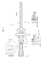
以下、本発明の実施の形態を図面に基づいて詳細に説明する。図1および図2は、携帯用工具の一例である刈込機つまりヘッジトリマを示している。この刈込機10は、動力源としての電動モータ11を収容する動力源収容部12とメインハンドル13とが一体となった携帯用工具本体つまりケーシング14を有しており、ケーシング14は動力源収容部12とこれの後部側のメインハンドル13とを有している。ケーシング14の前端部には、先端工具としてのブレード組立体つまりブレードアッセンブリ15が設けられており、ブレードアッセンブリ15はケーシング14の前端部から前方に突出している。
Hereinafter, embodiments of the present invention will be described in detail with reference to the drawings. 1 and 2 show a trimming machine, that is, a hedge trimmer, which is an example of a portable tool. The
ブレードアッセンブリ15は、ケーシング14にブラケット16により固定されるガイドバー17を有し、ガイドバー17には、それぞれ棒状の板材により形成され2つのトリミング刃つまりブレード18,19が長手方向に往復動自在に装着されている。電動モータ11の出力軸20は、動力変換機構21により出力軸20の回転運動が減速されてブレード18,19の直線往復動に変換され、電動モータ11によりブレード18,19は駆動される。
The
ケーシング14の前端部にはサブハンドル22が設けられており、作業者が植え込みや生垣の枝葉等の樹木を作業対象物としてこれを剪定作業する際には、一方の手でメインハンドル13を把持し、他方の手でサブハンドル22を把持しながら、刈込機10が操作される。
A
ケーシング14の後端部には、電動モータ11に電力を供給するための電池が組み込まれた電池パック23が着脱自在に装着されている。メインハンドル13にはトリガースイッチ24が組み込まれており、このトリガースイッチ24はメインハンドル13に設けられた操作レバーつまりトリガー25によりオンオフ操作される。トリガー25が作業者によりオン操作されると、電動モータ11に電力が供給されて電動モータ11は回転駆動される。
A
動力変換機構21は、ケーシング14に回転自在に支持された支持軸26に取り付けられるカム歯車27を有している。このカム歯車27に電動モータ11の出力軸20の回転を減速して伝達するために、出力軸20に固定されたピニオン28に噛み合う減速歯車29が支持軸31によりケーシング14に回転自在に装着され、支持軸31に取り付けられて減速歯車29と一体に回転するピニオン32がカム歯車27に噛み合っている。このように、ピニオン28とこれよりも大径の減速歯車29とからなる減速歯車対と、ピニオン32とこれよりも大径のカム歯車27とからなる減速歯車対との2段の減速歯車対により、出力軸20の回転は減速されてカム歯車27に伝達される。
The
カム歯車27の内外両側面には支持軸26の回転中心に対して偏心させて円形の偏心カム33,34が設けられている。内側の偏心カム33と外側の偏心カム34は、カム歯車27の回転方向にほぼ180度位相がずれている。一方のブレード18の基端部にはケーシング14の内側に突出して連結ピン35が設けられ、他方のブレード19の基端部には外側に突出して連結ピン36が設けられている。連結ピン35にはカムロッド37の一端部が揺動自在に連結され、このカムロッド37の他端部に形成された嵌合孔には偏心カム33が回転自在に嵌合されている。連結ピン36にはカムロッド38の一端部が揺動自在に連結され、このカムロッド38の他端部に形成された嵌合孔には偏心カム34が回転自在に嵌合されている。したがって、出力軸20が回転駆動されると、カム歯車27の回転運動がカムロッド37,38によりブレード18,19の直線往復運動に変換される。両方の偏心カム33,34の中心は支持軸26の中心に対して円周方向にほぼ180度位相がずれているので、カム歯車27が回転駆動されると、対をなす2つブレード18,19の一方は前進する方向に駆動され、他方は後退する方向に駆動される。このように、両方のブレード18,19は相互に逆方向に直線駆動され、それぞれのブレード18,19に設けられた切刃により樹木の剪定作業が行われる。
Circular
ケーシング14の上面であってメインハンドル13の先端部には、図1に示されるように、操作表示パネル41が配置されている。操作表示パネル41は、図2に示されるように、ホルダ42の表面側に設けられており、ホルダ42はその前後両端部に設けられた凸部42a,42bをケーシング14の凹部に係合させることによりケーシング14に取り付けられる。操作表示パネル41は、図1に示されるように、刈込機10の駆動情報を表示する駆動情報表示部43と操作スイッチ部44とを有している。操作スイッチ部44を操作することにより、電動モータ11の回転速度が設定されるとともに駆動情報表示部43に表示される複数の駆動情報のうち特定の駆動情報が選択される。駆動情報表示部43には、ブレード18,19の作動速度に対応した電動モータ11の回転速度と、電池の残量とが駆動情報の表示内容として表示され、何れの駆動情報を駆動情報表示部43に表示するかが操作スイッチ部44の操作により切り換えられて選択される。このように、駆動情報表示部43は、モータ回転速度と電池の残量との両方の表示部を兼用するようにした表示部となっている。
As shown in FIG. 1, an
駆動情報の内容としてのモータ回転速度と電池の残存量との何れを表示するかの選択は、操作スイッチ部44の操作態様つまり操作方法によって識別される。例えば、操作スイッチ部44が1秒以上長く押されたときには、駆動情報として電池の残存量が駆動情報表示部43に表示される。一方、操作スイッチ部44が押し込まれる時間が例えば1秒以下の短い時間のときには、駆動情報としての作動速度が表示される。これと同時に、操作スイッチ部44が短時間操作されたときには、電動モータ11の回転数が1段階高められる。なお、駆動情報の内容を選択するための操作態様としては、上述のように、操作スイッチ部44が押される操作時間つまりオン時間により選択する場合に限られず、操作回数によって駆動情報の内容が選択されるようにしても良い。その場合には、例えば、操作スイッチ部44が1回押されたときには、速度を表示し、単位時間内に複数回操作スイッチ部44が押されたときには電池の残量を表示する。
The selection of whether to display the motor rotation speed or the remaining battery amount as the content of the drive information is identified by the operation mode of the
駆動情報表示部43はLEDからなる4つの発光部45a〜45dを有している。これらの発光部45a〜45dがブレード18,19の作動速度つまりモータ回転速度を表示する場合には、発光部45a〜45dの点灯数により4段階に回転速度が表示される。例えば、全ての発光部45a〜45dが点灯しているときには、回転速度が最高速度であることが表示され、1つの発光部45aのみが点灯しているときには、回転速度が最低速度であることが表示され、点灯数が増加するに従って回転速度が速いことが表示される。一方、電池の残存容量については、例えば、2つの発光部45c,45dが点灯しているときには、電池が満充電の状態であることを表示し、1つの発光部45dのみが点灯しているときには、電池の残存容量が少なくなっていることを表示する。両方の発光部45c,45dが点灯されていないときには、電池の残存容量がないことを表示する。ただし、残存容量についても、4段階で表示するようにしても良く、ブレードの作動速度についても4段階に限られることなく、発光部の数を変更することにより、任意の段階で作動速度を表示することができる。また、電池の残存容量を表示する形態としては、2つの発光部45c,45dを点灯させる形態に代えて、これらを点滅させる形態としても良く、逆に、回転速度を表示する場合に発光部を点滅させ、電池の残存容量を表示する場合には発光部を点灯させるようにしても良い。
The drive
このように、操作スイッチ部44は電動モータ11の回転速度を設定入力する機能と、駆動情報表示部43に点灯表示される駆動情報の内容を切り換える機能とを有しており、両方の機構を兼用している。駆動情報表示部43と操作スイッチ部44とを操作表示パネル41に1つずつ設け、単一の駆動情報表示部43と単一の操作スイッチ部44とにそれぞれ複数の機能を兼用させることにより、それぞれを大型化することなく、操作表示パネル41を小型化することができる。操作表示パネルが小型化されると、刈込機10の製造コストを低減することができるだけでなく、駆動情報表示部43と操作スイッチ部44とが見やすくなり、操作スイッチ部44の操作性が高められる。更に、従来のような個別の表示部やスイッチ部が設けられたスペースに本実施の形態の駆動情報表示部43及び操作スイッチ部44を設ける場合には、これらを大きくすることができるため視認性及び操作性を高めることができる。しかも、操作表示パネル41は、ケーシング14のうちメインハンドル13の前端部に設けられているので、メインハンドル13を把持している片方の手でメインハンドル13を把持したままの状態で操作スイッチ部44を操作することができ、スイッチ操作の操作性が高められる。特に、メインハンドル13の先端部はケーシング14の前側に向かうに従って上向きに傾斜しており、その傾斜部分14dに操作表示パネル41が設けられているので、スイッチの操作性と、表示部の目視性とが良好となる。
As described above, the
すなわち、ケーシング14は上下方向(図2の上下方向)において最も突出する(外側に位置する)2つの頂部14a,14bを有する。一方の頂部14aは動力源収容部12の最も突出して位置であり、他方の頂部14bは電池パック23を取り付ける電池パック取付部14cの最も突出した位置である。操作表示パネル41は2つの頂部14,14bを結ぶ仮想線よりも凹んだ位置に設けられている。尚、電池パック23が頂部14bよりも外側に突出する場合には電池パック23の頂部と動力源収容部12の頂部14aの仮想線よりも凹んだ位置としてもよい。この構成により操作表示パネル41を外からの外力から保護することができる。例えば刈込機10を逆さまに置いた際(図2で上下反転)に、頂部14a,14bが接地面に接触することになり、操作表示パネル41は接地面に接触することなく保護することができる。
That is, the
更に、操作表示パネル41はメインハンドル13よりも前方側(動力源収容部12側)のケーシング14に設けられているため、作業者がメインハンドル13を把持しても隠れることがなく視認性を高めることができる。特に、上記したように傾斜部分14dに設けることで、操作表示パネル41がメインハンドル13側(すなわち作業者側)を向くようになるため、一層視認性を高めることができる。更に、傾斜部分14dはメインハンドル13と隣接するケーシング14の部分となるため、メインハンドル13を把持しながら操作表示パネル41を操作することができるため操作性も高めることができる。
Further, since the
ホルダ42の背面には図2に示されるように基板46が設けられており、この基板46はケーブルにより制御回路47に接続されている。制御回路47はマイクロプロセッサとメモリとを有し、トリガースイッチ24と操作スイッチ部44からの出力信号と、刈込機10に設けられた各種センサからの出力信号とがマイクロプロセッサに送られ、これらの出力信号に基づいてマイクロプロセッサは電動モータ11と駆動情報表示部43とに制御信号を出力する。
A
図3は刈込機10の制御部の制御回路47を示すブロック図である。マイクロプロセッサからなる演算部50には、トリガースイッチ24の出力信号がスイッチ操作検出回路51を介して入力されるとともに、操作スイッチ部44の出力信号がスイッチ操作検出回路52を介して入力される。電動モータ11は三相のブラシレスのモータであり、巻線コイル53には電池パック23内に収容された電池23aからの直流がインバータ54により、u相、v相、w相の三相の交流に変換されて巻線コイル53に供給される。演算部50は、予め図示しないメモリに記憶された正弦波に相当するPWM信号を、作業者により設定されたモータ回転速度に応じて制御信号出力回路55に出力し、制御信号出力回路55はインバータ54の3組のスイッチング素子(トランジスタやFET)Q1〜Q6に駆動信号を出力する。電動モータ11には、電動モータ11の回転子の回転を検出するために、ホール素子等からなる3つの位置センサ56a〜56cが120度置きに設けられており、それぞれの位置センサ56a〜56cの検出信号は、回転子位置検出回路57に出力される。回転子位置検出回路57の出力信号は演算部50とモータ回転数検出回路58とに送られ、演算部50は回転子位置検出回路57からの信号に基づいてインバータ54のトランジスタに切換信号を出力する。モータ回転数検出回路58は、演算部50にモータ回転数に基づくフィードバック信号を出力する。電動モータ11の巻線コイル53に電池23aから供給される電流を検出するために電池23aの出力線にはモータ電流検出回路59が設けられており、電動モータ11に過度の電流が流れた場合には、電動モータ11の回転が停止される。
FIG. 3 is a block diagram showing the
図4は操作表示パネル部の操作表示制御のアルゴリズムを示すフローチャートである。トリガー25を作業者が操作することによってトリガースイッチ24がオンされると、ステップS1において駆動情報表示部43には設定速度が表示されるとともに表示された速度となるように電動モータ11の回転数が制御される。例えば、刈込機10の直前の使用状態における電動モータ11の回転速度が最低回転数に設定されていた場合には、電動モータ11は最低回転数に設定されるとともに、駆動情報表示部43の4つの発光部45a〜45dのうちの1つが点灯される。これにより、作業者には電動モータ11の回転数が最低回転数であることが表示される。ステップS2において操作スイッチ部44が押されてオンとなったことが検出されると、ステップS3において操作スイッチ部44のオン時間をカウントする。ステップS4においては、操作スイッチ部44のオン時間が所定の設定時間A(msec)を経過したか否かが判定され、操作スイッチ部44のオンが設定時間A経過したときには、駆動情報表示部43の表示が電池残量の表示に切り換えられる(ステップS5)。この設定時間Aとしては、500msec程度に設定されている。
FIG. 4 is a flowchart showing an algorithm for operation display control of the operation display panel unit. When the
電池残量の表示は、ステップS6において操作スイッチ部44のオン操作が終了するまで継続され、操作スイッチ部44がオフされると、ステップS1の設定速度表示に切り換えられる。一方、ステップS4で設定時間Aが経過する前に、操作スイッチ部44のオン操作が終了したことが、ステップS7において判定されたときには、ステップS8において電動モータ11の設定速度が1段階高められるとともに、高められた速度が駆動情報表示部43に点灯表示される。例えば、電動モータ11の回転速度が最低回転速度の状態のもとで、ステップS8により1段階分だけ設定速度が切り換えられると、2段階目の設定速度で電動モータ11が駆動されるとともに、2つの発光部45a,45bが点灯されて2段階目の設定速度で電動モータ11が駆動されていることが表示される。電動モータ11が最高回転速度で回転されているときに、ステップS8により1段階分だけ設定速度が切り換えられると、電動モータ11の回転速度は最低速度に戻される。このように、駆動情報表示部43はモータ回転速度を表示する設定速度表示モードが基本となっており、操作スイッチ部44の操作時間により電池残量を表示する残量表示モードに切り換えられるようになっている。
The display of the remaining battery level is continued until the ON operation of the
上述した操作表示パネル41の駆動情報表示部43には、電池の残量と電動モータ11の回転速度とを表示するようにしているが、これに加えて、電池の寿命と電動モータ11の寿命のいずれか一方または両方を点灯させるようにすると、駆動情報表示部43にはこれらも表示されることになる。或いは、インバータ回路54を構成するスイッチング素子Q1〜Q6の寿命や温度情報、インバータ回路54(電動モータ11)に流れる電流値を表示させるようにしても良い。さらに、ブラシ付きの電動モータが駆動源として使用されるときには、ブラシの寿命を表示させるようにしても良く、先端工具としてのブレード18,19の切刃の寿命を表示するようにしても良い。
The drive
図1および図2は、携帯用工具としての刈込機10を示しているが、図1に示される操作表示パネル41を適用することができる携帯用工具としては、刈込機10に限られない。動力源がケーシングに組み込まれて作業者が手に持って作業が行われるものであれば、例えば、丸鋸、ドライバ、インパクトドライバ、ハンマ、ハンマドリル、ジグソー、グラインダ、ブロワ等の他の携帯用工具にも、図1に示される操作表示パネル41を搭載することができる。
1 and 2 show the trimming
本発明は前記実施の形態に限定されるものではなく、その要旨を逸脱しない範囲で種々変更可能である。例えば、携帯用工具の駆動源としては、上述した電動モータに限られず、エンジンを動力源とする携帯用工具にも上述した操作表示パネル41を設けることかできる。その場合には、燃料タンクの残存容量を駆動情報として操作表示パネル41に点灯表示ないし点滅表示させることができる。或いは、動力源として交流電源(商用電源)を用いる工具であっても適用することができる。その場合には、商用電源からの入力電圧を駆動情報として操作表示パネル41に点灯表示ないし点滅表示させることができる。また、携帯用工具として可搬型の工具に限るものではなく、卓上型(定置型)の工具(例えば卓上切断機)にも適用することができる。
The present invention is not limited to the above-described embodiment, and various modifications can be made without departing from the scope of the invention. For example, the drive source of the portable tool is not limited to the above-described electric motor, and the above-described
10…刈込機、11…電動モータ、12…動力源収容部、13…メインハンドル、14…ケーシング、15…ブレードアッセンブリ、16…ブラケット、17…ガイドバー、18,19…ブレード、20…出力軸、21…動力変換機構、22…サブハンドル、23…電池パック、23a…電池、24…トリガースイッチ、25…トリガー、26…支持軸、27…カム歯車、28…ピニオン、29…減速歯車、31…支持軸、32…ピニオン、33,34…偏心カム、35,36…連結ピン、37,38…カムロッド、41…操作表示パネル、42…ホルダ、43…駆動情報表示部、44…操作スイッチ部、45a〜45d…発光部、46…基板、47…制御回路。
DESCRIPTION OF
Claims (12)
少なくとも前記動力源の設定速度と前記動力源としての電動モータに電力を供給する電池の残量とを含む駆動情報を表示する駆動情報表示部及び前記駆動情報表示部に表示される駆動情報を選択する操作スイッチ部が設けられた操作表示パネル部を有し、
前記操作表示パネル部を前記ケーシングの上下方向における頂部を結ぶ仮想線よりも凹んだ位置に配置し、単一の前記操作スイッチ部の操作により前記駆動情報表示部の表示が前記動力源の設定速度と前記電池の残量とで切り換えられ、
前記操作スイッチ部により前記設定速度の設定を変更可能とし、
単一の前記操作スイッチ部の操作態様により前記駆動情報表示部による駆動情報の表示内容の切り換えと前記設定速度の設定の変更の何れかが選択されて行われることを特徴とする携帯用工具。 A casing having a handle portion gripped by an operator, a power source accommodating portion that is located in front of the handle portion and accommodates a power source, and is positioned in front of the power source accommodating portion and driven by the power source. A portable tool having a tip tool,
A driving information display unit that displays driving information including at least a set speed of the power source and a remaining amount of a battery that supplies power to the electric motor as the power source, and driving information displayed on the driving information display unit are selected. Having an operation display panel section provided with an operation switch section
The operation display panel unit is disposed at a position recessed from an imaginary line connecting the tops in the vertical direction of the casing, and the drive information display unit displays the set speed of the power source by operating the single operation switch unit. And the remaining battery level ,
The setting speed setting can be changed by the operation switch unit,
A portable tool characterized in that either switching of drive information display content by the drive information display unit or change in setting of the set speed is selected according to an operation mode of the single operation switch unit .
前記操作表示パネル部を前記傾斜部に設けたことを特徴とする請求項3記載の携帯用工具。 The casing has an inclined portion facing the handle portion side that is inclined upward as it goes from the handle portion to the power source accommodating portion,
The portable tool according to claim 3, wherein the operation display panel is provided on the inclined portion.
少なくとも前記動力源の設定速度と前記動力源としての電動モータに電力を供給する電池の残量とを含む複数の駆動情報のうち特定の駆動情報を表示する駆動情報表示部と、前記複数の駆動情報のうち前記駆動情報表示部に表示される特定の駆動情報を選択する操作スイッチ部とが設けられた操作表示パネル部を設け、
単一の前記操作スイッチ部の操作により、前記駆動情報表示部の表示が前記動力源の設定速度と前記電池の残量とで切り換えられ、
前記操作スイッチ部により前記設定速度の設定を変更可能とし、
単一の前記操作スイッチ部の操作態様により前記駆動情報表示部による駆動情報の表示内容の切り換えと前記設定速度の設定の変更の何れかが選択されて行われることを特徴とする携帯用工具。 A portable tool having a casing having a power source accommodating portion for accommodating a power source and a handle gripped by an operator,
A drive information display unit that displays specific drive information among a plurality of drive information including at least a set speed of the power source and a remaining amount of a battery that supplies electric power to the electric motor as the power source; and the plurality of drives An operation display panel unit provided with an operation switch unit for selecting specific drive information displayed on the drive information display unit among the information;
By the operation of the single operation switch unit, the display of the drive information display unit is switched between the set speed of the power source and the remaining battery level ,
The setting speed setting can be changed by the operation switch unit,
A portable tool characterized in that either switching of drive information display content by the drive information display unit or change in setting of the set speed is selected according to an operation mode of the single operation switch unit .
少なくとも前記動力源の設定速度と前記動力源としての電動モータに電力を供給する電池の残量とを含む複数の駆動情報のうち特定の駆動情報を表示する駆動情報表示部と、前記複数の駆動情報のうち前記駆動情報表示部に表示される特定の駆動情報を選択する操作スイッチ部とが設けられた操作表示パネル部を有し、
前記動力源の設定速度の表示と前記電池の残量の表示を操作スイッチ部の異なる操作態様に対応させ、前記操作スイッチ部の前記異なる操作態様により前記駆動情報表示部による駆動情報の表示内容を切り換え、
前記操作スイッチ部により前記設定速度の設定を変更可能とし、
単一の前記操作スイッチ部の操作態様により前記駆動情報表示部による駆動情報の表示内容の切り換えと前記設定速度の設定の変更の何れかが選択されて行われることを特徴とする携帯用工具。 A portable tool having a casing having a power source accommodating portion for accommodating a power source and a handle gripped by an operator,
A drive information display unit that displays specific drive information among a plurality of drive information including at least a set speed of the power source and a remaining amount of a battery that supplies electric power to the electric motor as the power source; and the plurality of drives An operation display panel unit provided with an operation switch unit for selecting specific drive information displayed on the drive information display unit among the information;
The display of the set speed of the power source and the display of the remaining amount of the battery are made to correspond to different operation modes of the operation switch unit, and the display contents of the drive information by the drive information display unit are changed according to the different operation modes of the operation switch unit. Switching ,
The setting speed setting can be changed by the operation switch unit,
A portable tool characterized in that either switching of drive information display content by the drive information display unit or change in setting of the set speed is selected according to an operation mode of the single operation switch unit .
Priority Applications (5)
| Application Number | Priority Date | Filing Date | Title |
|---|---|---|---|
| JP2012239785A JP6098117B2 (en) | 2012-10-31 | 2012-10-31 | Portable tools |
| DE202013104882.8U DE202013104882U1 (en) | 2012-10-31 | 2013-10-31 | Portable tool |
| CN201320684643.3U CN203566655U (en) | 2012-10-31 | 2013-10-31 | Portable tool |
| US14/069,017 US9555537B2 (en) | 2012-10-31 | 2013-10-31 | Portable tool |
| FR1302530A FR2997333A1 (en) | 2012-10-31 | 2013-10-31 | PORTABLE TOOL |
Applications Claiming Priority (1)
| Application Number | Priority Date | Filing Date | Title |
|---|---|---|---|
| JP2012239785A JP6098117B2 (en) | 2012-10-31 | 2012-10-31 | Portable tools |
Publications (3)
| Publication Number | Publication Date |
|---|---|
| JP2014087896A JP2014087896A (en) | 2014-05-15 |
| JP2014087896A5 JP2014087896A5 (en) | 2015-11-12 |
| JP6098117B2 true JP6098117B2 (en) | 2017-03-22 |
Family
ID=50235736
Family Applications (1)
| Application Number | Title | Priority Date | Filing Date |
|---|---|---|---|
| JP2012239785A Active JP6098117B2 (en) | 2012-10-31 | 2012-10-31 | Portable tools |
Country Status (5)
| Country | Link |
|---|---|
| US (1) | US9555537B2 (en) |
| JP (1) | JP6098117B2 (en) |
| CN (1) | CN203566655U (en) |
| DE (1) | DE202013104882U1 (en) |
| FR (1) | FR2997333A1 (en) |
Families Citing this family (39)
| Publication number | Priority date | Publication date | Assignee | Title |
|---|---|---|---|---|
| JP6032400B2 (en) * | 2012-08-15 | 2016-11-30 | 日立工機株式会社 | Chainsaw |
| CN104303861A (en) * | 2014-09-13 | 2015-01-28 | 广东技术师范学院 | Garden curved surface cutting hedge trimmer |
| CN104617853A (en) * | 2014-10-28 | 2015-05-13 | 常州格力博有限公司 | Pruning machine speed regulation control method |
| JP6357086B2 (en) * | 2014-11-26 | 2018-07-11 | 株式会社マキタ | Electric equipment |
| US10375901B2 (en) | 2014-12-09 | 2019-08-13 | Mtd Products Inc | Blower/vacuum |
| JP6504898B2 (en) * | 2015-04-20 | 2019-04-24 | 株式会社マキタ | Shoulder type fluid device |
| US10652956B2 (en) | 2016-06-22 | 2020-05-12 | The Gillette Company Llc | Personal consumer product with thermal control circuitry and methods thereof |
| US10680494B2 (en) | 2016-06-24 | 2020-06-09 | Black & Decker Inc. | Control scheme for power tool having a brushless motor |
| USD808743S1 (en) * | 2016-08-24 | 2018-01-30 | Lankim, LLC | Chainsaw cover for an electric knife |
| JP2018114739A (en) * | 2017-01-21 | 2018-07-26 | ソトウ株式会社 | Portable welding apparatus and welding method |
| SI3446834T1 (en) * | 2017-08-24 | 2020-04-30 | Scheppach Fabrikation Von Holzbearbeitungsmaschinen Gmbh | Electric hammer |
| WO2019061090A1 (en) * | 2017-09-27 | 2019-04-04 | Changzhou Globe Co., Ltd. | Battery compartment for power tools |
| JP2019134693A (en) * | 2018-02-05 | 2019-08-15 | 株式会社マキタ | Hedge trimmer |
| JP6976187B2 (en) * | 2018-02-05 | 2021-12-08 | 株式会社マキタ | Electric tool |
| EP3536463A1 (en) * | 2018-03-09 | 2019-09-11 | Blount, INC. | Power tool activation control systems and methods |
| JP7212826B2 (en) * | 2018-03-19 | 2023-01-26 | 京セラインダストリアルツールズ株式会社 | Electric tool |
| CN111819049B (en) * | 2018-03-30 | 2022-04-26 | 吉列有限责任公司 | Shaving razor system |
| US11607820B2 (en) | 2018-03-30 | 2023-03-21 | The Gillette Company Llc | Razor handle with movable members |
| USD874061S1 (en) | 2018-03-30 | 2020-01-28 | The Gillette Company Llc | Shaving razor cartridge |
| CA3092881A1 (en) | 2018-03-30 | 2019-10-03 | The Gillette Company Llc | Razor handle with movable members |
| WO2019191178A1 (en) | 2018-03-30 | 2019-10-03 | The Gillette Company Llc | Razor handle with movable members |
| CN111867795B (en) | 2018-03-30 | 2022-03-18 | 吉列有限责任公司 | Razor handle |
| US11123888B2 (en) | 2018-03-30 | 2021-09-21 | The Gillette Company Llc | Razor handle with a pivoting portion |
| WO2019191163A1 (en) | 2018-03-30 | 2019-10-03 | The Gillette Company Llc | Razor handle with a pivoting portion |
| JP7104168B2 (en) | 2018-03-30 | 2022-07-20 | ザ ジレット カンパニー リミテッド ライアビリティ カンパニー | Razor handle with pivot part |
| EP3774223A1 (en) | 2018-03-30 | 2021-02-17 | The Gillette Company LLC | Shaving razor cartridge |
| EP3774230A1 (en) | 2018-03-30 | 2021-02-17 | The Gillette Company LLC | Razor handle with a pivoting portion |
| EP3857654A4 (en) | 2018-09-28 | 2022-06-01 | Hubbell Incorporated | Power tool with crimp localization |
| JP7209597B2 (en) * | 2019-07-18 | 2023-01-20 | 株式会社マキタ | electric work machine |
| CN110549304B (en) * | 2019-09-05 | 2024-07-05 | 上海沃施实业有限公司 | Handle for garden tool |
| US11865679B2 (en) | 2019-10-11 | 2024-01-09 | Ingersoll-Rand Industrial U.S., Inc. | Battery powered impact wrench |
| CN213411880U (en) * | 2019-12-06 | 2021-06-11 | 苏州宝时得电动工具有限公司 | Cutting tool |
| EP3865250B1 (en) | 2020-02-14 | 2022-07-06 | Andreas Stihl AG & Co. KG | Handheld tool with operating element and display panel |
| CN114051850A (en) * | 2020-08-10 | 2022-02-18 | 创科无线普通合伙 | Hedge trimmer |
| US11412631B2 (en) | 2020-08-26 | 2022-08-09 | Snap-On Incorporated | PCB with integrated switches |
| WO2022105587A1 (en) * | 2020-11-17 | 2022-05-27 | Globe (jiangsu) Co., Ltd. | Backpack blower, backpack assembly and backpack power assembly |
| CN112425400B (en) * | 2020-11-26 | 2022-03-15 | 常州卡夫特机械有限公司 | Method and device for intelligently trimming vegetation clumps and electric mower |
| KR102586158B1 (en) * | 2022-08-08 | 2023-10-05 | 우승종 | Smart stick with impact box |
| DE102023202065A1 (en) * | 2023-03-08 | 2024-09-12 | Robert Bosch Gesellschaft mit beschränkter Haftung | Hand tool with a human machine interface |
Family Cites Families (35)
| Publication number | Priority date | Publication date | Assignee | Title |
|---|---|---|---|---|
| JPS5566712U (en) * | 1978-10-31 | 1980-05-08 | ||
| JPS5566712A (en) | 1978-11-14 | 1980-05-20 | Matsushita Electric Ind Co Ltd | Photo-detector |
| DE2926111A1 (en) * | 1979-06-28 | 1981-01-08 | Scintilla Ag | ELECTRIC HAND TOOL |
| US4412158A (en) * | 1980-02-21 | 1983-10-25 | Black & Decker Inc. | Speed control circuit for an electric power tool |
| GB8812292D0 (en) * | 1988-05-24 | 1988-06-29 | Black & Decker Inc | Improvements in/relating to power tools |
| IT223418Z2 (en) * | 1990-02-07 | 1995-07-19 | Spiranyl S A R 1 S R L | DEVICE FOR SCREWING AND UNSCREWING SCREWS, BOLTS AND NUTS. |
| GB9320181D0 (en) * | 1993-09-30 | 1993-11-17 | Black & Decker Inc | Improvements in and relating to power tools |
| US5445479A (en) * | 1994-08-17 | 1995-08-29 | Hillinger; George | Ergonomically designed, electrically energized hand drill having a housing, longitudinally aligned with a hand, wrist and forearm support |
| US6536536B1 (en) * | 1999-04-29 | 2003-03-25 | Stephen F. Gass | Power tools |
| US6443675B1 (en) * | 2000-02-17 | 2002-09-03 | Roto Zip Tool Corporation | Hand-held power tool |
| AUPQ618800A0 (en) * | 2000-03-10 | 2000-04-06 | Bayly Design Associates Pty Ltd | Power tool |
| US7282818B2 (en) * | 2002-04-10 | 2007-10-16 | Credo Technology Corporation | Power hand tool having a proximity detector |
| JP2005144564A (en) * | 2003-11-11 | 2005-06-09 | Matsushita Electric Works Ltd | Portable electric tool |
| DE10353302A1 (en) * | 2003-11-11 | 2005-06-09 | C. & E. Fein Gmbh | Electric tool and method for controlling a power tool |
| DE102004030037B4 (en) * | 2003-11-19 | 2012-01-12 | Milwaukee Electric Tool Corp. | accumulator |
| US20060220612A1 (en) * | 2005-03-31 | 2006-10-05 | Feldmann William M | Modular panel for a power tool |
| GB2426390B (en) * | 2005-05-17 | 2009-02-18 | Milwaukee Electric Tool Corp | Power tool, battery, charger and method of operating the same |
| JP4922031B2 (en) * | 2007-03-19 | 2012-04-25 | 日立工機株式会社 | Portable tools |
| US7722435B2 (en) * | 2007-06-13 | 2010-05-25 | Black & Decker Inc. | Sander |
| US20090013477A1 (en) * | 2007-07-13 | 2009-01-15 | Agronin Michael L | Combination tool for electrical tasks |
| EP2030709A3 (en) * | 2007-08-29 | 2013-01-16 | Positec Power Tools (Suzhou) Co., Ltd. | Power tool |
| US8230600B2 (en) * | 2007-09-17 | 2012-07-31 | The Gillette Company | Cartridge detachment sensor |
| EP2218559B1 (en) * | 2009-02-13 | 2012-08-15 | Trisa Holding AG | Body care device |
| DE102009012178B4 (en) * | 2009-02-27 | 2019-07-04 | Andreas Stihl Ag & Co. Kg | Battery operated, handheld implement |
| DE102009012175A1 (en) * | 2009-02-27 | 2010-09-02 | Andreas Stihl Ag & Co. Kg | Electrical appliance with a battery pack |
| JP5825750B2 (en) * | 2009-03-03 | 2015-12-02 | 日立工機株式会社 | Electric working machine |
| US8833485B2 (en) * | 2009-04-08 | 2014-09-16 | Husqvarna Ab | Battery-powered portable tools |
| JP2011115919A (en) * | 2009-12-07 | 2011-06-16 | Max Co Ltd | Power tool |
| JP2012011504A (en) * | 2010-06-30 | 2012-01-19 | Hitachi Koki Co Ltd | Power tool |
| JP5591131B2 (en) * | 2011-01-05 | 2014-09-17 | 株式会社マキタ | Electric tool |
| JP5709087B2 (en) * | 2011-02-04 | 2015-04-30 | 日立工機株式会社 | Electric tool |
| EP2674261B1 (en) | 2011-02-10 | 2018-04-04 | Makita Corporation | Electric tool |
| JP2012239785A (en) | 2011-05-24 | 2012-12-10 | Panasonic Corp | Dishwasher |
| CN103747922A (en) * | 2011-08-26 | 2014-04-23 | 胡斯华纳有限公司 | Guide and control assembly |
| JP6070072B2 (en) * | 2012-10-31 | 2017-02-01 | 日立工機株式会社 | Power tool |
-
2012
- 2012-10-31 JP JP2012239785A patent/JP6098117B2/en active Active
-
2013
- 2013-10-31 DE DE202013104882.8U patent/DE202013104882U1/en not_active Expired - Lifetime
- 2013-10-31 CN CN201320684643.3U patent/CN203566655U/en not_active Expired - Lifetime
- 2013-10-31 FR FR1302530A patent/FR2997333A1/en active Pending
- 2013-10-31 US US14/069,017 patent/US9555537B2/en active Active
Also Published As
| Publication number | Publication date |
|---|---|
| CN203566655U (en) | 2014-04-30 |
| US20140116737A1 (en) | 2014-05-01 |
| JP2014087896A (en) | 2014-05-15 |
| DE202013104882U1 (en) | 2014-02-18 |
| FR2997333A1 (en) | 2014-05-02 |
| US9555537B2 (en) | 2017-01-31 |
Similar Documents
| Publication | Publication Date | Title |
|---|---|---|
| JP6098117B2 (en) | Portable tools | |
| JP6024470B2 (en) | Electric tool | |
| CN106998168B (en) | Electric working machine | |
| EP2747948B1 (en) | Guide and control assembly | |
| CN106964836B (en) | Cutting machine | |
| JP4922031B2 (en) | Portable tools | |
| US10491148B2 (en) | Electric working machine | |
| JP2021045844A (en) | Electric work machine | |
| JP2017001115A (en) | Working tool | |
| JP6454522B2 (en) | Working machine | |
| US9769990B2 (en) | Power tool | |
| JP2010110875A (en) | Motor rotation controlling device for driving power tool | |
| CN201534325U (en) | Multi-functional electric hand tool | |
| WO2013038789A1 (en) | Electric tool | |
| JP4789617B2 (en) | Electric tool | |
| JP2020124766A (en) | Electric work machine | |
| JP6252970B2 (en) | Electric tool | |
| WO2021220992A1 (en) | Work machine | |
| CN114303679A (en) | Hand-held electric tool | |
| JP2018008356A (en) | Power tool | |
| CN213614523U (en) | Reciprocating saw | |
| JP6821346B2 (en) | Electric screwdriver | |
| CN115674071A (en) | Electric tool and impact driver | |
| JP2012065622A (en) | Power tool and attachment |
Legal Events
| Date | Code | Title | Description |
|---|---|---|---|
| A521 | Written amendment |
Free format text: JAPANESE INTERMEDIATE CODE: A523 Effective date: 20150918 |
|
| A621 | Written request for application examination |
Free format text: JAPANESE INTERMEDIATE CODE: A621 Effective date: 20150918 |
|
| A977 | Report on retrieval |
Free format text: JAPANESE INTERMEDIATE CODE: A971007 Effective date: 20160622 |
|
| A131 | Notification of reasons for refusal |
Free format text: JAPANESE INTERMEDIATE CODE: A131 Effective date: 20160705 |
|
| A521 | Written amendment |
Free format text: JAPANESE INTERMEDIATE CODE: A523 Effective date: 20160905 |
|
| A131 | Notification of reasons for refusal |
Free format text: JAPANESE INTERMEDIATE CODE: A131 Effective date: 20161101 |
|
| A521 | Written amendment |
Free format text: JAPANESE INTERMEDIATE CODE: A523 Effective date: 20161226 |
|
| TRDD | Decision of grant or rejection written | ||
| A01 | Written decision to grant a patent or to grant a registration (utility model) |
Free format text: JAPANESE INTERMEDIATE CODE: A01 Effective date: 20170124 |
|
| A61 | First payment of annual fees (during grant procedure) |
Free format text: JAPANESE INTERMEDIATE CODE: A61 Effective date: 20170206 |
|
| R150 | Certificate of patent or registration of utility model |
Ref document number: 6098117 Country of ref document: JP Free format text: JAPANESE INTERMEDIATE CODE: R150 |
|
| S533 | Written request for registration of change of name |
Free format text: JAPANESE INTERMEDIATE CODE: R313533 |
|
| R350 | Written notification of registration of transfer |
Free format text: JAPANESE INTERMEDIATE CODE: R350 |