JP6097285B2 - Region limiter synchronized with scanning motion - Google Patents
Region limiter synchronized with scanning motion Download PDFInfo
- Publication number
- JP6097285B2 JP6097285B2 JP2014517685A JP2014517685A JP6097285B2 JP 6097285 B2 JP6097285 B2 JP 6097285B2 JP 2014517685 A JP2014517685 A JP 2014517685A JP 2014517685 A JP2014517685 A JP 2014517685A JP 6097285 B2 JP6097285 B2 JP 6097285B2
- Authority
- JP
- Japan
- Prior art keywords
- ray
- detector
- ray source
- movement
- scan
- Prior art date
- Legal status (The legal status is an assumption and is not a legal conclusion. Google has not performed a legal analysis and makes no representation as to the accuracy of the status listed.)
- Expired - Fee Related
Links
Images


Classifications
-
- A—HUMAN NECESSITIES
- A61—MEDICAL OR VETERINARY SCIENCE; HYGIENE
- A61B—DIAGNOSIS; SURGERY; IDENTIFICATION
- A61B6/00—Apparatus for radiation diagnosis, e.g. combined with radiation therapy equipment
- A61B6/02—Devices for diagnosis sequentially in different planes; Stereoscopic radiation diagnosis
- A61B6/025—Tomosynthesis
-
- A—HUMAN NECESSITIES
- A61—MEDICAL OR VETERINARY SCIENCE; HYGIENE
- A61B—DIAGNOSIS; SURGERY; IDENTIFICATION
- A61B6/00—Apparatus for radiation diagnosis, e.g. combined with radiation therapy equipment
- A61B6/06—Diaphragms
-
- A—HUMAN NECESSITIES
- A61—MEDICAL OR VETERINARY SCIENCE; HYGIENE
- A61B—DIAGNOSIS; SURGERY; IDENTIFICATION
- A61B6/00—Apparatus for radiation diagnosis, e.g. combined with radiation therapy equipment
- A61B6/44—Constructional features of apparatus for radiation diagnosis
- A61B6/4429—Constructional features of apparatus for radiation diagnosis related to the mounting of source units and detector units
- A61B6/4452—Constructional features of apparatus for radiation diagnosis related to the mounting of source units and detector units the source unit and the detector unit being able to move relative to each other
-
- A—HUMAN NECESSITIES
- A61—MEDICAL OR VETERINARY SCIENCE; HYGIENE
- A61B—DIAGNOSIS; SURGERY; IDENTIFICATION
- A61B6/00—Apparatus for radiation diagnosis, e.g. combined with radiation therapy equipment
- A61B6/50—Clinical applications
- A61B6/502—Clinical applications involving diagnosis of breast, i.e. mammography
-
- A—HUMAN NECESSITIES
- A61—MEDICAL OR VETERINARY SCIENCE; HYGIENE
- A61B—DIAGNOSIS; SURGERY; IDENTIFICATION
- A61B6/00—Apparatus for radiation diagnosis, e.g. combined with radiation therapy equipment
- A61B6/54—Control of apparatus or devices for radiation diagnosis
- A61B6/547—Control of apparatus or devices for radiation diagnosis involving tracking of position of the device or parts of the device
-
- A—HUMAN NECESSITIES
- A61—MEDICAL OR VETERINARY SCIENCE; HYGIENE
- A61B—DIAGNOSIS; SURGERY; IDENTIFICATION
- A61B6/00—Apparatus for radiation diagnosis, e.g. combined with radiation therapy equipment
- A61B6/04—Positioning of patients; Tiltable beds or the like
- A61B6/0407—Supports, e.g. tables or beds, for the body or parts of the body
- A61B6/0414—Supports, e.g. tables or beds, for the body or parts of the body with compression means
-
- A—HUMAN NECESSITIES
- A61—MEDICAL OR VETERINARY SCIENCE; HYGIENE
- A61B—DIAGNOSIS; SURGERY; IDENTIFICATION
- A61B6/00—Apparatus for radiation diagnosis, e.g. combined with radiation therapy equipment
- A61B6/44—Constructional features of apparatus for radiation diagnosis
- A61B6/4476—Constructional features of apparatus for radiation diagnosis related to motor-assisted motion of the source unit
Landscapes
- Health & Medical Sciences (AREA)
- Life Sciences & Earth Sciences (AREA)
- Medical Informatics (AREA)
- Engineering & Computer Science (AREA)
- Radiology & Medical Imaging (AREA)
- Molecular Biology (AREA)
- Biophysics (AREA)
- Nuclear Medicine, Radiotherapy & Molecular Imaging (AREA)
- Optics & Photonics (AREA)
- Pathology (AREA)
- Physics & Mathematics (AREA)
- Biomedical Technology (AREA)
- Heart & Thoracic Surgery (AREA)
- High Energy & Nuclear Physics (AREA)
- Surgery (AREA)
- Animal Behavior & Ethology (AREA)
- General Health & Medical Sciences (AREA)
- Public Health (AREA)
- Veterinary Medicine (AREA)
- Dentistry (AREA)
- Oral & Maxillofacial Surgery (AREA)
- Apparatus For Radiation Diagnosis (AREA)
Description
本発明は、概して、マンモグラフィ、トモシンセシス及びラジオグラフィの分野におけるX線イメージング装置に関する。 The present invention relates generally to X-ray imaging devices in the fields of mammography, tomosynthesis and radiography.
トモシンセシスは、人間の体の一部、例えばマンモグラフィ検査における乳房の3次元画像を再構成するために使用される。このような画像を作るための典型的な装置は、X線源(104、204、304)の焦点が乳房等の対象に対して回転することを可能にされることを必要とし、対象(108、208、308)内の各場所を通る投影角間隔がスキャンされて各投影角に関する個々の投影像を作る。多数の2D投影像を有するデータを用いて、3D画像への再構成が、計算ステップとして逆投影を含むアルゴリズムを実行するコンピュータを用いて可能である。アルゴリズムの例は、フィルタ逆投影、代数的再構成及び1995年からのLange−Fessler Convexアルゴリズムである。トモシンセシス画像の構成を可能にするX線イメージング装置の例は、例えば、特許文献1及び特許文献2である。 Tomosynthesis is used to reconstruct a three-dimensional image of a part of the human body, for example a breast in a mammography examination. A typical apparatus for producing such an image requires that the focus of the x-ray source (104, 204, 304) be allowed to rotate relative to an object such as a breast, and the object (108 , 208, 308) are scanned for projection angle intervals through each location to produce individual projection images for each projection angle. Using data with multiple 2D projection images, reconstruction into 3D images is possible using a computer that performs an algorithm that includes backprojection as a computational step. Examples of algorithms are filter backprojection, algebraic reconstruction and the Lange-Fessler Convex algorithm from 1995. Examples of X-ray imaging apparatuses that enable the construction of tomosynthesis images are, for example, Patent Document 1 and Patent Document 2.
従来技術では、投影角、すなわち切断角度を作る能力を持つX線システムが提案されている。一般的に、このような解決方法は、検出器(105、205、305)及びスキャンされることになる対象(108、208、308)に対するX線源の直線又は回転運動を可能にし、検出器(105、205、305)はまた、直線又は回転の方法で移動可能になるように適合され得る。X線源(104、204、304)が静止し且つ検出器(105、205、305)がX線源(104、204、304)及び調べられる対象の周りを回転する、2D画像、並びに、X線源(104、204、304)が検出器(105、205、305)及び調べられる対象に対して移動可能である、同じシステムにおける3Dトモシンセシス画像の両方の作成を可能にすることが提案されている。このようなシステムの例は例えば、特許文献1及び特許文献2に見られる。 In the prior art, an X-ray system has been proposed that has the ability to create a projection angle, ie, a cutting angle. In general, such a solution allows a linear or rotational movement of the X-ray source relative to the detector (105, 205, 305) and the object (108, 208, 308) to be scanned. (105, 205, 305) can also be adapted to be movable in a linear or rotational manner. A 2D image in which the X-ray source (104, 204, 304) is stationary and the detector (105, 205, 305) rotates around the X-ray source (104, 204, 304) and the object to be examined, and X It has been proposed to allow the creation of both 3D tomosynthesis images in the same system, where the source (104, 204, 304) is movable relative to the detector (105, 205, 305) and the object being examined. Yes. Examples of such a system can be found in Patent Document 1 and Patent Document 2, for example.
可変トモシンセシス画像を生成する能力を持つ従来技術に記載されたようなX線システムは、より重いシステム、及び望ましくは、投影角及び画像の後に探すものを達成するために、伝統的な2DのX線イメージングシステムより多くの自由度を持つより複雑なスキャン運動を必要とする。しかし、このようなシステムのマンモグラフィ検査中のスキャン運動は、予め設定された運動計画に基づいてオペレータによって設定される。これは、最適な投影角が、例えば、サイズ、厚さ及び対象の他の特性に関して、スキャンされる各対象(108、208、308)に対して達成されないので、画像の品質にマイナスの影響を与える。さらに、このようなシステムは、直接的又は間接的な方法でスキャンされる対象の特性に基づいて避けられるべきである特定のスキャン運動を防ぐ能力を有していない。 X-ray systems such as those described in the prior art with the ability to generate variable tomosynthesis images are traditional 2D X-rays to achieve heavier systems, and preferably what is looked for after projection angles and images. Requires more complex scanning motion with more degrees of freedom than line imaging systems. However, the scan motion during mammography examination of such a system is set by the operator based on a preset motion plan. This has a negative impact on image quality since an optimal projection angle is not achieved for each scanned object (108, 208, 308), for example with respect to size, thickness and other characteristics of the object. give. Furthermore, such systems do not have the ability to prevent certain scanning movements that should be avoided based on the characteristics of the object being scanned in a direct or indirect manner.
さらに、従来技術の解決方法は、スキャン運動の適応制御を記載しておらず、外部データが、対象のスキャン中、切断角度を最適化するために考慮される。 Furthermore, the prior art solution does not describe adaptive control of the scanning motion, and external data is taken into account to optimize the cutting angle during the scanning of the object.
従来技術のマンモグラフィ応用に使用されるシールド装置では、患者及びオペレータを散乱から保護するために箱又は伸縮式シールド手段を使用することが提案されている。このような例示的な従来技術は、例えば、特許文献3に見ることができ、特許文献3は、スキャン装置を開示し、X線源はスキャン運動中固定される。シールド手段はここでは、その高さがスキャンされることになる対象のサイズに基づく患者乳房支持部の据付けに基づいて垂直方向に自動的に設置される。このような解決方法の目的は、散乱放射線を防ぐためであり、スキャンされる対象の画像の生成又は改良を加えない直接放射線を防ぐためではない。 In shield devices used in prior art mammography applications, it has been proposed to use boxes or telescoping shield means to protect patients and operators from scattering. Such an exemplary prior art can be found, for example, in US Pat. No. 6,057,086, which discloses a scanning device, where the X-ray source is fixed during the scanning motion. The shield means is here automatically installed in the vertical direction based on the installation of the patient breast support based on the size of the object whose height is to be scanned. The purpose of such a solution is to prevent scattered radiation, not to prevent direct radiation that does not create or improve the image of the object being scanned.
従来技術では、高忠実度合成2D画像を生み出すようにレシーバ読み出しをスキャン運動と同期させるために、X線イメージングシステムにおいて位置エンコーダを用いることを提案している。ここでは、エンコーダは、検出器アレイ運動に応じて信号を生成するために使用され、これらの信号は、ピクセルのアレイに渡る電荷シフトをトリガするために使用される。電荷シフトはエンコーダ出力を参照するので、同期は、駆動速度の又は他の不規則性に起因する変動にもかかわらず、維持される。 The prior art suggests using a position encoder in an x-ray imaging system to synchronize the receiver readout with the scanning motion to produce a high fidelity composite 2D image. Here, the encoder is used to generate signals in response to detector array motion, and these signals are used to trigger charge shifts across the array of pixels. Since charge shift refers to the encoder output, synchronization is maintained despite fluctuations due to drive speed or other irregularities.
他の従来技術の文献では、トモシンセシスは、人間の体の一部、例えばマンモグラフィ検査における乳房の3次元画像を再構成するために使用される方法である。このような画像を作るための典型的な装置は、X線源の焦点が乳房等の対象に対して動くことを可能にされることを必要とし、対象内の各場所を通る投影角の間隔がスキャンされて各投影角に関する個々の投影像を作る。多数の2D投影像を有するデータを用いて、3D画像への再構成が、計算ステップとしていわゆる逆投影を含む再構成アルゴリズムを実行するコンピュータを用いて可能である。トモシンセシス画像の構成を可能にするX線イメージング装置を開示する文献の例は、例えば、特許文献1及び特許文献2である。 In other prior art documents, tomosynthesis is a method used to reconstruct a three-dimensional image of a part of the human body, for example a breast in a mammography examination. A typical apparatus for creating such an image requires that the focus of the x-ray source be allowed to move relative to a subject such as a breast, and the spacing of projection angles through each location within the subject. Are scanned to produce individual projection images for each projection angle. Using data with a large number of 2D projection images, reconstruction into 3D images is possible using a computer that executes a reconstruction algorithm including so-called backprojection as a calculation step. Examples of documents disclosing an X-ray imaging apparatus that enables the construction of tomosynthesis images are, for example, Patent Document 1 and Patent Document 2.
可変スキャン運動を伴うトモシンセシススキャナは、より重いシステム、及び望ましくは、投影角及び画像を得るとともに最適化するために、伝統的なX線イメージングシステムより多くの自由度を持つより複雑なスキャン運動を必要とする。しかし、3D画像の再構成は、モーションブラーを再構成された画像に生じさせないように、正確なスキャン運動を必要とするが、これは、例えば、あるスキャンの運動を制御するために使用される様々な作動機構において、並びに完全な方法で制御することができないモータがスキャン運動を制御することに起因して、遊びが時間とともに広がる傾向がある、記載された思いシステムに不適合である。モーションブラーに類似するアーチファクトなしに正確な画質を得るために、従来技術は、高価な運動制御システム及びモータ、並びにバックラッシュ又は撓みなしの力の伝達に頼らなくてはならない場合がある。 Tomosynthesis scanners with variable scanning motions allow heavier systems, and preferably more complex scanning motions with more degrees of freedom than traditional X-ray imaging systems, to obtain and optimize projection angles and images. I need. However, reconstruction of 3D images requires precise scanning motion so that motion blur does not occur in the reconstructed image, which is used, for example, to control the motion of certain scans. Due to the various actuation mechanisms, as well as the motor that cannot be controlled in a complete manner, controlling the scanning movement, it is incompatible with the described thought system where play tends to spread over time. In order to obtain accurate image quality without artifacts similar to motion blur, the prior art may have to rely on expensive motion control systems and motors and the transmission of force without backlash or deflection.
本発明の目的は、従来技術の欠点の幾つかを軽減し、スキャン運動が外部データに基づいて最適化されるX線イメージングシステムのための改良された装置を提供することである。 The object of the present invention is to alleviate some of the disadvantages of the prior art and to provide an improved apparatus for an X-ray imaging system in which the scanning motion is optimized based on external data.
1つの実施形態によれば、X線装置は、X線ビームを放射するように適合されたX線源と、X線源のX線ビームを受けるように適合された検出器と、を有し、X線源はX線装置の第1の部分に対して動かされるように適合され、検出器はX線装置の第1の部分に対して動かされるように適合され、X線装置はさらに、X線源及び検出器の運動を制御するための制御ユニットを有し、X線源及び検出器は、X線装置の第1の部分に対して回転するように適合され、さらに、X線ビームは、X線源及び検出器の運動中に本質的に検出器に向けられ、制御ユニットは、外部データを受信するように適合され、制御ユニットはさらに、X線源及び検出器の運動を外部データに基づいて制御するように適合され、X線装置はさらに、少なくとも1つの位置調整可能な圧迫パドル、及び少なくとも1つの圧迫パドルの位置に対応するパドル位置データを出力するように適合された少なくとも1つの圧迫パドルの位置を決定するための手段を有し、制御ユニットによって受信される外部データは、パドル位置データを含む。 According to one embodiment, the X-ray device comprises an X-ray source adapted to emit an X-ray beam and a detector adapted to receive the X-ray beam of the X-ray source. The X-ray source is adapted to be moved relative to the first part of the X-ray device, the detector is adapted to be moved relative to the first part of the X-ray device; A control unit for controlling the movement of the X-ray source and the detector, the X-ray source and the detector being adapted to rotate relative to the first part of the X-ray device; Is essentially directed to the detector during movement of the X-ray source and detector, the control unit is adapted to receive external data, and the control unit further transfers the movement of the X-ray source and detector to the external Adapted to control based on the data, the x-ray device further comprises at least one position. An adjustable compression paddle and means for determining the position of at least one compression paddle adapted to output paddle position data corresponding to the position of the at least one compression paddle, received by the control unit The external data includes paddle position data.
他の実施形態によれば、検出器は、スキャン運動中にリアルタイムでX線ビームの特性を感知するように適合され、検出器はさらに、X線ビームの特性に対応するX線ビームデータを出力するように適合され、X線源及び検出器のスキャン運動の残りを制御するための制御ユニットによって受信される外部データは、X線ビームデータを含む。 According to another embodiment, the detector is adapted to sense the characteristic of the X-ray beam in real time during the scanning motion, and the detector further outputs X-ray beam data corresponding to the characteristic of the X-ray beam. The external data adapted to and received by the control unit for controlling the remainder of the scanning motion of the X-ray source and detector includes X-ray beam data.
他の実施形態によれば、検出器は、スキャン運動中にX線源からの衝突光子を受けるように適合され、検出器はさらに、衝突光子の量に基づいてX線強度を検出するように適合され、制御ユニットはさらに、スキャンされることになる対象がX線ビームからの光子を減衰させ始めるとき、X線ビームに置かれた対象のスキャンがより低い強度を検出することによって開始される検出器から外部データを受信するように適合される。 According to another embodiment, the detector is adapted to receive an impinging photon from an x-ray source during a scanning motion, and the detector further detects the x-ray intensity based on the amount of impinging photon. Adapted and the control unit is further started by detecting a lower intensity of the scan of the object placed in the x-ray beam when the object to be scanned begins to attenuate photons from the x-ray beam It is adapted to receive external data from the detector.
他の実施形態によれば、制御ユニットは、トモシンセシススキャン運動が実行されるように、スキャン運動及び/又は外部データに基づくX線源及び検出器の残りのスキャン運動を制御するように適合され、X線ビームに置かれた対象の断層撮影投影角度が外部データに基づいて最適化される。 According to another embodiment, the control unit is adapted to control the scanning movement and / or the remaining scanning movement of the X-ray source and detector based on external data, so that a tomosynthesis scanning movement is performed, The tomographic projection angle of the object placed on the X-ray beam is optimized based on the external data.
他の実施形態によれば、制御ユニットは、検出器の第1の端部が少なくとも対象のスキャン中に減少したカウントレートを感知するとき、少なくともX線源の速度が減少するように、X線源及び検出器の運動を制御するように適合される。 According to another embodiment, the control unit may be configured to cause the X-ray source to decrease at least when the first end of the detector senses a decreased count rate at least during the scan of the object. Adapted to control the movement of the source and detector.
他の実施形態によれば、第1の検出されたX線強度は少なくともX線源の速度を第1の速度に減少させ、第2の検出されたX線強度はX線源の速度を第2の速度に減少させ、第1の検出されたX線強度が第2の検出されたX線強度より低い場合、第1の速度は、少なくとも対象のスキャン中、第2の速度より低い。 According to another embodiment, the first detected x-ray intensity reduces at least the x-ray source speed to the first speed, and the second detected x-ray intensity reduces the x-ray source speed to the first speed. If the first detected X-ray intensity is lower than the second detected X-ray intensity, the first speed is lower than the second speed at least during the scan of the object.
他の実施形態によれば、制御ユニットは、検出器の速度が、少なくとも対象のスキャン中、X線源の速度より低くなるように、検出器の速度を制御するように適合される。 According to another embodiment, the control unit is adapted to control the speed of the detector such that the speed of the detector is lower than the speed of the x-ray source at least during the scan of the object.
他の実施形態によれば、制御ユニットは、X線源及び検出器の速度の間の比が、対象のスキャン中のより高い検出されたX線強度に比べて及び/又は対象の2つの別々のスキャンの間と比べて、より低い検出されたX線強度に関して低くなるように、X線源及び検出器の速度を制御するように適合される。 According to another embodiment, the control unit may be configured such that the ratio between the x-ray source and the detector speed is compared to the higher detected x-ray intensity during the scan of the object and / or two separate It is adapted to control the speed of the x-ray source and detector so that it is lower for lower detected x-ray intensities as compared to during the scan.
他の実施形態によれば、制御ユニットは、比が、X線源及び検出器の運動中、X線源が水平方向に検出器を通過することを可能にするよう十分高くなるように、X線源及び検出器の速度を制御するように適合され、カウントレートはスキャンされることになる対象に対応する。 According to another embodiment, the control unit is configured so that the ratio is high enough to allow the X-ray source to pass the detector in a horizontal direction during X-ray source and detector movement. Adapted to control the speed of the source and detector, the count rate corresponds to the object to be scanned.
他の実施形態によれば、制御ユニットは、少なくとも1つの圧迫パドルの第1の位置が少なくともX線源の速度を第1の速度に設定し、少なくとも1つの圧迫パドルの第2の位置が少なくともX線源の速度を第2の速度に設定するように、対象のスキャン中、少なくとも1つの圧迫パドルの位置に基づいて、少なくともX線源の速度を制御するように適合され、少なくとも1つの圧迫パドルの第1の位置が少なくとも1つの圧迫パドルの第2の位置より垂直方向において高い場合、第1の速度は第2の速度より低い。 According to another embodiment, the control unit is configured such that the first position of the at least one compression paddle sets at least the speed of the x-ray source to the first speed and the second position of the at least one compression paddle is at least Adapted to control at least the speed of the x-ray source based on the position of the at least one compression paddle during the scan of the object, so as to set the speed of the x-ray source to a second speed; If the first position of the paddle is higher in the vertical direction than the second position of the at least one compression paddle, the first speed is lower than the second speed.
他の実施形態によれば、制御ユニットは、X線源及び検出器の速度の間の比が、少なくとも対象のスキャン中、圧迫パドルの低い位置に比べて圧迫パドルの高い位置に関して低くなるように、X線源及び検出器の速度を制御するように適合される。 According to another embodiment, the control unit is such that the ratio between the x-ray source and detector velocities is low for the high position of the compression paddle compared to the low position of the compression paddle, at least during the scan of the subject. , Adapted to control the speed of the x-ray source and detector.
他の実施形態によれば、制御ユニットは、比が、少なくとも対象のスキャン中、X線源が水平方向に検出器を通過することを可能にするよう十分高くなるように、X線源及び検出器の速度を制御するように適合される。 According to another embodiment, the control unit may detect the X-ray source and the detection so that the ratio is high enough to allow the X-ray source to pass through the detector in a horizontal direction at least during the scan of the object. Adapted to control the speed of the vessel.
他の実施形態によれば、制御ユニットは、本質的にX線装置の第1の部分を通って延びる垂直線に対するX線源と検出器の中心との間の直線が角度(α)を定めるように、X線源及び検出器の運動を制御するように適合され、検出器はX線源より前にスキャンされることになる対象に向かって動き、角度(α)は、対象のスキャンが開始されるまでのX線源及び検出器の運動の開始中に設定され、角度(α)は、少なくとも1つの圧迫パドルの位置とともに減少する。 According to another embodiment, the control unit has an angle (α) defined by a straight line between the X-ray source and the center of the detector with respect to a vertical line extending essentially through the first part of the X-ray device. So that the motion of the x-ray source and detector is adapted, the detector moves towards the object to be scanned before the x-ray source, and the angle (α) Set during the beginning of the movement of the x-ray source and detector until it is started, the angle (α) decreases with the position of at least one compression paddle.
他の実施形態によれば、制御ユニットは、X線源及び検出器の速度の間の比が、角度(α)が第1の値を有し、0度を超え且つ対象のスキャンの端部において第2の値を有するように、十分高くなるように、X線源及び検出器の速度を制御するように適合され、第1及び第2の値は、圧迫パドルとの衝突を避ける制約の下で本質的に最大化される。 According to another embodiment, the control unit has a ratio between the x-ray source and detector velocities where the angle (α) has a first value and is greater than 0 degrees and the end of the scan of the object Is adapted to control the speed of the x-ray source and detector to be sufficiently high so as to have a second value at the first and second values of the constraint to avoid a collision with the compression paddle Essentially maximized below.
他の実施形態によれば、制御ユニットは、ローカル断層撮影投影角度の広がりが全スキャン運動中に一定のままになるように、角度(α)を制御するように適合される。 According to another embodiment, the control unit is adapted to control the angle (α) so that the spread of the local tomography projection angle remains constant during the entire scan movement.
他の実施形態によれば、制御ユニットは、角度(α)が制限値を超えないように、X線源及び検出器の運動を制御するように適合され、制限値は、X線源の位置及び検出器の位置とともに連続的に変化し、さらに、圧迫パドルの位置及び種類に依存する。 According to another embodiment, the control unit is adapted to control the movement of the X-ray source and the detector such that the angle (α) does not exceed the limit value, the limit value being the position of the X-ray source. And continuously with the detector position, and further depends on the position and type of the compression paddle.
他の実施形態によれば、角度(α)の制限値は、少なくとも1つの圧迫パドルの位置に依存する。 According to another embodiment, the limit value of the angle (α) depends on the position of at least one compression paddle.
他の実施形態によれば、装置は2つの圧迫パドルを有し、対象は前記2つの圧迫パドルの間で圧迫されることができ、角度(α)の制限値は、圧迫パドルの間の距離が増加する場合、減少する。 According to another embodiment, the device has two compression paddles, the subject can be compressed between the two compression paddles, and the angle (α) limit is the distance between the compression paddles If increases, it decreases.
他の実施形態によれば、X線装置はさらにスキャンアームを有し、X線源はスキャンアームの第1の位置に配置され、検出器はスキャンアームの第2の位置に配置される。 According to another embodiment, the X-ray device further comprises a scan arm, the X-ray source is arranged at a first position of the scan arm and the detector is arranged at a second position of the scan arm.
他の実施形態によれば、スキャンアームの第1の位置は、スキャンアームの第1の端部に対応し、スキャンアームの第2の位置は、スキャンアームの第2の端部に対応する。 According to another embodiment, the first position of the scan arm corresponds to the first end of the scan arm and the second position of the scan arm corresponds to the second end of the scan arm.
他の実施形態によれば、スキャンアームはさらに、スキャンアーム上のX線源及び検出器の間に配置されたマルチスリットコリメータを有し、制御ユニットは、少なくとも1つの圧迫パドルとコリメータとの間の衝突が防がれるように、X線源及び検出器の運動を制御するように適合される。 According to another embodiment, the scan arm further comprises a multi-slit collimator disposed between the X-ray source and the detector on the scan arm, and the control unit is between the at least one compression paddle and the collimator. It is adapted to control the movement of the X-ray source and detector so that collisions of the X-ray are prevented.
他の実施形態によれば、制御ユニットは、X線源に対する第1の変向点及び検出器に対する第1の変向点それぞれにおいて、X線源及び/又は検出器の方向を変えるように適合され、X線源は第1の変向点に達した後に第2の方向に動く又は停止するとともに検出器は第1の変向点に達した後に第2の方向に動く又は停止し、第2の方向は、第1の変向点に達する前の第1の方向と本質的に反対である。 According to another embodiment, the control unit is adapted to change the direction of the X-ray source and / or detector at a first turning point with respect to the X-ray source and at a first turning point with respect to the detector, respectively. The X-ray source moves or stops in the second direction after reaching the first turning point, and the detector moves or stops in the second direction after reaching the first turning point, The direction of 2 is essentially the opposite of the first direction before reaching the first turning point.
他の実施形態によれば、制御ユニットはさらに、ゼロ又はそれより多い、変向点の数、及びそれらの位置を外部データに依存して選択するように適合される。 According to another embodiment, the control unit is further adapted to select the number of turning points and their positions depending on the external data, zero or more.
他の実施形態によれば、制御ユニットはさらに、外部エータに依存して、対象スキャンの切断角度を達成する制約下において変向点の数を最小化するように適合される。 According to another embodiment, the control unit is further adapted to minimize the number of turning points under the constraint of achieving the cutting angle of the target scan, depending on the external eta.
他の実施形態によれば、制御ユニットは、X線源及び検出器の両方がそれらの第1の変向点に向かって動くとき、検出器が第1の変向点に達する前にX線源が第1の変向点に達するように、X線源及び検出器の運動を制御するように適合される。 According to another embodiment, the control unit may be configured such that when both the X-ray source and the detector move toward their first turning point, the X-ray is detected before the detector reaches the first turning point. It is adapted to control the movement of the x-ray source and detector such that the source reaches the first turning point.
他の実施形態によれば、制御ユニットは、X線源及び検出器が、第1の変向点に達した後すぐに方向を変えるとともに第2の方向に動き始めるように、X線源及び検出器の運動を制御するように適合される。 According to another embodiment, the control unit may be configured so that the X-ray source and detector change direction immediately after reaching the first turning point and start to move in the second direction. Adapted to control the movement of the detector.
他の実施形態によれば、制御ユニットは、第2の変向点においてX線源の方向を変えるように適合され、制御ユニットは、検出器が第1の変向点に達するとき、X線源が方向を変えるとともに第2の変向点において第1の方向に動くことを開始するように、X線源及び検出器の運動を制御するように適合される。 According to another embodiment, the control unit is adapted to change the direction of the X-ray source at the second turning point, and the control unit is adapted to change the X-ray when the detector reaches the first turning point. The source is adapted to control the movement of the x-ray source and detector to change direction and begin to move in the first direction at the second turning point.
他の実施形態によれば、X線は、第1の変向点に達した後、X線源及び検出器の他方が第1の変向点に達するまで停止し、その後X線源は第2の方向に動き始める。 According to another embodiment, after the X-ray reaches the first turning point, it stops until the other of the X-ray source and the detector reaches the first turning point, after which the X-ray source is It starts to move in the direction of 2.
他の実施形態によれば、X線源は、検出器より高い速度で動く。 According to other embodiments, the x-ray source moves at a higher speed than the detector.
他の実施形態によれば、制御ユニットはさらに、X線源及び検出器の位置に基づいて、X線源及び検出器の運動を制御するように適合される。 According to another embodiment, the control unit is further adapted to control the movement of the X-ray source and detector based on the position of the X-ray source and detector.
他の実施形態によれば、位置は、予め定められている。 According to another embodiment, the position is predetermined.
他の実施形態によれば、制御ユニットは、X線源の速度が検出器の速度より高くなるように、X線源及び検出器の運動を制御するように適合される。 According to another embodiment, the control unit is adapted to control the movement of the X-ray source and the detector such that the speed of the X-ray source is higher than the speed of the detector.
他の実施形態によれば、予め定められた位置は、対象のスキャン中に達した位置に対応し、それによって特定のスキャン運動を必要とする対象の領域が識別され、X線源及び検出器の速度の比は増加する。 According to another embodiment, the predetermined position corresponds to a position reached during the scan of the object, whereby an area of the object that requires a particular scanning motion is identified, and the X-ray source and detector The speed ratio increases.
他の実施形態によれば、X線源の運動を最小化するトレードオフ下で、検出される対象内の断層撮影角度を最大化するための最適化が実行される。 According to another embodiment, optimization is performed to maximize the tomographic angle within the detected object, under the trade-off of minimizing X-ray source motion.
他の実施形態によれば、X線源の予め定められた位置に到達し、検出器の予め定められた位置に到達するとき、少なくともX線源の速度は減少する。 According to another embodiment, when the predetermined position of the X-ray source is reached and the predetermined position of the detector is reached, at least the speed of the X-ray source is reduced.
他の実施形態によれば、X線装置はさらに、位置に到達するとき乳房から生検サンプルを採取するための装置を有し、位置は、対象の領域が生検サンプリングを必要としていることが確認された位置に対応する。 According to another embodiment, the X-ray device further comprises a device for taking a biopsy sample from the breast when the position is reached, where the area of interest requires biopsy sampling. Corresponds to the confirmed position.
他の実施形態によれば、X線装置は上方部分及び下方部分を有し、X線源は第1のサスペンションアームの第1の端部に枢動可能に配置され、第1のサスペンションアームの第2の端部は、第2のサスペンションアームの第1の端部にスライド可能に配置され、第2のサスペンションアームの第2の端部は、下方部分に枢動可能に配置され、第1の直動ネジが、水平方向のX線源の運動を制御するためにX線源の近くのX線部分に配置され、第2の直動ネジが、水平方向の検出器組立体の運動を制御するために検出器組立体近くの下方部分に配置され、第3の直動ネジが、垂直方向のスキャンアームの運動を制御するために第2のサスペンションアームに配置される。 According to another embodiment, the X-ray device has an upper portion and a lower portion, and the X-ray source is pivotally disposed at the first end of the first suspension arm, The second end is slidably disposed on the first end of the second suspension arm, and the second end of the second suspension arm is pivotally disposed on the lower portion, Of the linear motion screw is placed in the X-ray portion near the X-ray source to control the motion of the horizontal X-ray source, and the second linear motion screw controls the motion of the horizontal detector assembly. A third linear screw is disposed on the second suspension arm to control the vertical scan arm movement, and is disposed in the lower portion near the detector assembly for control.
他の実施形態によれば、X線装置の第1の部分は、本質的に空間の中に固定される。 According to another embodiment, the first part of the X-ray device is essentially fixed in space.
他の実施形態によれば、X線装置は、X線ビームを放射するように適合されたX線源と、X線源のX線ビームを受けるように適合された検出器と、を有し、X線源は動かされるように設定され、検出器は動かされるように設定され、X線装置はさらに、X線源及び検出器の運動を制御するための制御ユニットを有し、さらに、X線ビームは、X線源及び検出器の運動中、本質的に検出器に向けられ、制御ユニットは、外部データを受信するように適合され、制御ユニットはさらに、外部データに基づいてX線源及び検出器の組み合わせの運動の経路を制御するように適合され、外部データは、対象に関するデータを含む。 According to another embodiment, the X-ray apparatus comprises an X-ray source adapted to emit an X-ray beam and a detector adapted to receive the X-ray beam of the X-ray source. The X-ray source is set to be moved, the detector is set to be moved, and the X-ray apparatus further comprises a control unit for controlling the movement of the X-ray source and the detector, The beam of rays is essentially directed to the detector during movement of the X-ray source and detector, the control unit is adapted to receive external data, and the control unit is further adapted to receive the X-ray source based on the external data. And adapted to control the path of motion of the detector combination, the external data includes data about the subject.
他の実施形態によれば、制御ユニットは、外部データに基づいて、スキャン運動中、それぞれ、第1の運動経路に沿ってX線源の運動を制御するように及び第2の運動経路に沿って検出器の運動を制御するように、適合される。 According to another embodiment, the control unit controls the movement of the X-ray source along the first movement path and along the second movement path, respectively, during the scanning movement based on the external data. Adapted to control the movement of the detector.
他の実施形態によれば、外部データは、スキャン運動中、制御ユニットによって受信される。 According to another embodiment, the external data is received by the control unit during the scanning movement.
他の実施形態によれば、外部データは、スキャンされることになる対象、又は関心領域の境界又は厚さに関連し、前記装置は、対象の位置決め後であるがスキャンを終了する前に、外部データを測定するための手段を有する。 According to another embodiment, the external data relates to the object to be scanned, or to the boundary or thickness of the region of interest, and the device is after positioning of the object but before ending the scan It has a means for measuring external data.
他の実施形態によれば、第1の運動経路に沿ったX線源の運動及び第2の運動経路に沿った検出器の運動は、組み合わされた運動経路に対応し、組み合わされた運動経路は、1つの軸に沿った位置及びX線源と検出器との間の角度を含む多次元パラメータ空間を通る曲線によって表されることができる。 According to another embodiment, the movement of the X-ray source along the first movement path and the movement of the detector along the second movement path correspond to the combined movement path and the combined movement path. Can be represented by a curve through a multi-dimensional parameter space including the position along one axis and the angle between the x-ray source and the detector.
他の実施形態によれば、第1の運動経路及び第2の運動経路は、ローカル断層撮影投影角を最適化するように及びX線源の運動を最小化するように適合される。 According to another embodiment, the first motion path and the second motion path are adapted to optimize the local tomographic projection angle and to minimize the motion of the x-ray source.
本発明の目的は、従来技術の欠点の幾つかを軽減し、X線放射を遮蔽するための改良された装置を提供することである。 The object of the present invention is to alleviate some of the disadvantages of the prior art and to provide an improved device for shielding X-ray radiation.
1つの実施形態によれば、X線装置は、X線ビームを放射するように適合されたX線源と、X線源のX線ビームを受けるように適合された検出器と、を有し、X線源はX線装置の第1の部分に対して動かされるように適合され、検出器はX線装置の第1の部分に対して動かされるように適合され、X線源及び検出器は、X線装置の第1の部分に対して回転するように適合され、さらに、X線ビームは、X線源及び検出器の運動中に本質的に検出器に向けられ、X線装置はさらに、X線源及び検出器の位置に対応する位置を感知するように、及び位置感知装置によって感知されたX線源及び検出器の位置に対応する位置信号を伝達するように適合された位置感知装置と、第1の側部及び第2の側部及び側部の間の開口を有する領域制限装置と、を有し、X線ビームは、開口を通過することを可能にされるが、第1及び第2の側部によって妨げられ、X線ビームは第1及び第2の側部によって吸収される。 According to one embodiment, the X-ray device comprises an X-ray source adapted to emit an X-ray beam and a detector adapted to receive the X-ray beam of the X-ray source. The X-ray source is adapted to be moved relative to the first part of the X-ray device and the detector is adapted to be moved relative to the first part of the X-ray device; Is adapted to rotate relative to the first part of the X-ray device, and the X-ray beam is essentially directed to the detector during X-ray source and detector movement, the X-ray device being Further, a position adapted to sense a position corresponding to the position of the X-ray source and detector and to transmit a position signal corresponding to the position of the X-ray source and detector sensed by the position sensing device. A sensing device and a region limiting device having an opening between the first side and the second side and side; A, X-rays beam is is it possible to pass through the opening, blocked by the first and second sides, X-rays beam is absorbed by the first and second sides.
他の実施形態によれば、領域制限装置の少なくとも第1の側部は、第1と第2の位置との間で、X線ビームの中心線に対して調整可能に移動可能であり、第1の側部は、第1の位置より第2の位置において、より大きい割合のX線ビームが領域制限装置を通過することを防ぎ、装置はさらに、位置感知装置からの位置信号を受信するように適合された第1の制御ユニットを有し、第1の制御ユニットは、位置信号に基づいて、少なくとも第1の側部の動きを制御するように適合される。 According to another embodiment, at least a first side of the region limiting device is adjustably movable between the first and second positions relative to the center line of the X-ray beam, The side of 1 prevents a greater proportion of the x-ray beam from passing through the region limiting device at the second position than at the first position, and the apparatus is further adapted to receive a position signal from the position sensing device. A first control unit adapted to control at least a first side movement based on the position signal.
他の実施形態によれば、第1の側部は、第1の位置に比べて、第1の位置と第2の位置との間の任意の位置において、大きい割合のX線照射が領域制限装置を通過することを防ぐ。 According to another embodiment, the first side has a region-limited X-ray exposure at any position between the first position and the second position compared to the first position. Prevents passing through the device.
他の実施形態によれば、第1の側部の第2の位置は、第1の側部の第1の位置より、X線ビームの中心に近い。 According to another embodiment, the second position of the first side is closer to the center of the X-ray beam than the first position of the first side.
他の実施形態によれば、X線装置はさらに、少なくとも第1の端部及び第2の端部を有する画像領域を有し、第1の側部は、X線照射が第1の画像端部の外側の領域に放射線を当てることを防ぐように、第2の位置に向かって動くように適合され、第2の側部は、X線照射が第2の画像端部の外側の領域を照射することを防ぐように、第2の位置に向かって動くように適合される。 According to another embodiment, the X-ray apparatus further comprises an image area having at least a first end and a second end, the first side being exposed to the first image end by X-ray irradiation. Adapted to move towards a second position so as to prevent the radiation from being applied to the area outside the part, the second side is adapted to move the X-ray irradiation over the area outside the second image edge. Adapted to move toward the second position to prevent irradiating.
他の実施形態によれば、X線装置はさらにスキャンアームを有し、X線源はスキャンアームの第1の位置に配置され、検出器はスキャンアームの第2の位置に配置され、領域制限装置は、X線源の運動が領域制限装置の運動を生じさせるように、スキャンアームの第3の位置に配置される。 According to another embodiment, the X-ray device further comprises a scan arm, the X-ray source is located at the first position of the scan arm, the detector is located at the second position of the scan arm, and the region restriction The apparatus is placed in a third position of the scan arm so that the movement of the X-ray source causes the movement of the area limiting device.
他の実施形態によれば、領域制限装置の開口は、X線源から見てX線ビームの中心線から第1の側部の端部への第1の角度vf1、X線源から見てX線ビームの中心線から第2の側部の端部への第2の角度vf2、を有し、vi2はX線源から見てX線ビームの中心線から第2の画像端部への角度であり、vi1はX線源から見てX線ビームの中心線から第1の画像端部への角度であり、vd2はX線源から見てX線ビームの中心線から検出器の第2の端部への角度であり、vd1はX線源から見てX線ビームの中心線から検出器の第1の端部への角度であり、第1の側部は、vi1<vd1の場合、vf1≦vi1となるように第1と第2の位置との間で動くように適合され、第2の側部は、vi2<vd2の場合、vf2≦vi2となるように、第1と第2の位置との間で動くように適合される。 According to another embodiment, the aperture of the region limiting device has a first angle v f1 from the center line of the X-ray beam to the end of the first side as viewed from the X-ray source, viewed from the X-ray source. And a second angle v f2 from the center line of the X-ray beam to the end of the second side, where v i2 is the second image end from the center line of the X-ray beam as viewed from the X-ray source. V i1 is the angle from the center line of the X-ray beam to the first image edge as viewed from the X-ray source, and v d2 is the center line of the X-ray beam as viewed from the X-ray source From the center line of the X-ray beam to the first end of the detector as viewed from the X-ray source, and v d1 is the angle from the first end of the detector to the first end of the detector. Is adapted to move between the first and second positions so that v f1 ≦ v i1 , if v i1 <v d1 , and the second side is v i2 <v d2 , V f2 ≦ It is adapted to move between the first and second positions to be v i2 .
他の実施形態によれば、第1の側部は、vi1>vd1の場合、vd1≦vf1≦vi1となるように、第1と第2の位置との間で動くように適合され、第2の側部は、vi2>vd2の場合、vd2≦vf2≦vi2となるように、第1と第2の位置との間で動くように適合される。 According to another embodiment, the first side moves between the first and second positions such that v d1 ≦ v f1 ≦ v i1 when v i1 > v d1. Adapted and the second side is adapted to move between the first and second positions such that if v i2 > v d2 then v d2 ≦ v f2 ≦ v i2 .
他の実施形態によれば、第1の側部は、vi1が減少する場合に第2の位置に向かって動くとともにvi1が増加する場合に第1の位置に向かって動き、第2の側部は、vi2が減少する場合に第2の位置に向かって動くとともにvi2が増加する場合に第1の位置に向かって動く。 According to another embodiment, the first side moves toward the second position when v i1 decreases and moves toward the first position when v i1 increases, and the second side The side moves toward the second position when v i2 decreases and moves toward the first position when v i2 increases.
他の実施形態によれば、X線装置は、複数のスキャンスイープを実行するように設定され、X線装置はさらに、X線源及び検出器の運動を制御するための第2の制御ユニットを有し、検出器は複数の検出器ラインを有し、第1の制御ユニットは、位置感知装置からの位置信号に基づいて、本質的に水平方向に延びる経路に沿った予め定められた位置における垂直線に対する各検出器ラインに向かうX線ビームの角度を計算するように適合され、第1の制御ユニットは、計算された角度を保存するように適合され、第1の制御ユニットは、水平方向に本質的に延びる経路に沿った各予め定められた位置において各計算された角度に対して1回より多くX線ビームが検出器ラインによって受けられることを防ぐように、領域制限装置の少なくとも第1の側部を制御するように適合される。 According to another embodiment, the X-ray device is configured to perform a plurality of scan sweeps, and the X-ray device further includes a second control unit for controlling the motion of the X-ray source and detector. And the detector has a plurality of detector lines, and the first control unit is based on a position signal from the position sensing device at a predetermined position along a path that extends essentially in the horizontal direction. Adapted to calculate the angle of the x-ray beam toward each detector line relative to the vertical line, the first control unit adapted to store the calculated angle, and the first control unit adapted to the horizontal direction At least one of the region limiters to prevent the X-ray beam from being received by the detector line more than once for each calculated angle at each predetermined position along a path that essentially extends to It is adapted to control the first side.
他の実施形態によれば、第2の制御ユニットは、X線源の第1の変向点及び検出器の第1の変向点それぞれにおいて、X線源及び/又は検出器の方向を変えるように適合され、X線源及び検出器は、変向点に達した後、変更点に達する前の第1の方向と本質的に反対の第2の方向に動き、主スキャン運動は、X線源が第1の変向点に達する前且つ検出器が第1の変向点に達した後のX線源及び検出器の運動を含み、バウンシングスキャン運動は、X線源が第1の変向点に達するときから検出器が同じ変向点に達するまでの、又はX線源が第1の変向点に達するときから、検出器が第1の変向点に達し、且つX線源が、X線源が再び運動の方向を変える第2の変向点に達するまでの、X線源及び検出器の運動を含み、第1の制御ユニットは、主スキャン中の保存された計算された角度をバウンシングスキャン中の計算された角度と比較するように適合され、第1の制御ユニットはさらに、主スキャンとバウンシングスキャン運動中のオーバーラップがある検出器ラインを特定するとともにマークするように適合され、第1の制御ユニットは、少なくとも第1の側部が本質的にX線ビームからマークされた検出器ラインをカバーするように、少なくとも第1の側部を第2の位置に向かって動かすように適合される。 According to another embodiment, the second control unit changes the direction of the X-ray source and / or detector at a first turning point of the X-ray source and a first turning point of the detector, respectively. The X-ray source and detector move in a second direction after reaching the turning point and in a second direction essentially opposite to the first direction before reaching the change point, and the main scanning motion is Including the movement of the X-ray source and detector before the source reaches the first turning point and after the detector reaches the first turning point, the bouncing scan movement includes From when the turning point is reached until the detector reaches the same turning point, or from when the X-ray source reaches the first turning point, the detector reaches the first turning point, and X-rays The source includes the movement of the X-ray source and detector until the X-ray source reaches a second turning point where the direction of movement is changed again. The first control unit is further adapted to compare the stored calculated angle during the can with the calculated angle during the bouncing scan, and the first control unit further includes a detector line with overlap during the main scan and the bouncing scan motion Is adapted to identify and mark the at least first side so that at least the first side essentially covers the detector line marked from the X-ray beam. Is adapted to move toward the second position.
他の実施形態によれば、第1及び第2の側部は、互いに相互に接続される。 According to another embodiment, the first and second sides are connected to each other.
他の実施形態によれば、領域制限装置は、開口を持つプレートを有する。 According to another embodiment, the area limiting device has a plate with openings.
他の実施形態によれば、領域制限装置は、開口を備える円筒形装置を有し、開口の第1の端部を定める円筒形装置の部分は第1の側部であり、開口の第2の端部を定める円筒形装置の部分は第2の側部であり、円筒形装置は、X線源周りの回転のために枢動可能に配置される。 According to another embodiment, the area limiting device comprises a cylindrical device with an opening, the portion of the cylindrical device defining the first end of the opening is the first side and the second of the opening. The portion of the cylindrical device that defines the end of this is the second side, and the cylindrical device is pivotally arranged for rotation about the x-ray source.
他の実施形態によれば、円筒形装置は、vi1<vf1の場合、角度vrot1=(vf1−vi1)に回転するように適合され、円筒形装置は、vi2<vf2の場合、角度vrot2=(vf2−vi2)に回転するように適合される。 According to another embodiment, the cylindrical device is adapted to rotate to an angle v rot1 = (v f1 −v i1 ), where v i1 <v f1 , and the cylindrical device is v i2 <v f2. for, is adapted to rotate to an angle v rot2 = (v f2 -v i2 ).
他の実施形態によれば、円筒形装置は、vi1>vd1の場合、角度vrot1=(vf1−vd1)に回転するように及びvi2>vd2の場合、角度vrot2=(vf2−vd2)に回転するように適合される。 According to another embodiment, a cylindrical device, v i1> v For d1, when the angle v rot1 = (v f1 -v d1 ) to rotate and v i2> v d2, the angle v ROT2 = It is adapted to rotate to (v f2 −v d2 ).
他の実施形態によれば、第2の側部は、第1の側部が第2の位置に向かって動くとき、第1の位置に向かって動くように、第2位置に向かって動くように、又は動かないように適合され、第2の側部は、大きい割合のX線ビームが第1の位置より第2の位置において領域制限装置を通過することを防ぐ。 According to another embodiment, the second side moves toward the second position, such that when the first side moves toward the second position, the second side moves toward the first position. Or adapted to not move, the second side prevents a greater proportion of the x-ray beam from passing through the region limiting device in the second position than in the first position.
他の実施形態によれば、第2の側部の第2の位置は、第2の側部の第1の位置より、領域の中心線に近い。 According to another embodiment, the second position of the second side is closer to the center line of the region than the first position of the second side.
他の実施形態によれば、第1及び第2の側部の運動は、電気モータによって行われ、モータは第1の制御ユニットによって制御される。 According to another embodiment, the movement of the first and second sides is performed by an electric motor, which is controlled by a first control unit.
他の実施形態によれば、第1の側部及び第2の側部は、少なくとも1つの直線レールに沿ってスライドするように適合される。 According to another embodiment, the first side and the second side are adapted to slide along at least one straight rail.
他の実施形態によれば、第1の側部及び第2の側部は、L形状である。 According to another embodiment, the first side and the second side are L-shaped.
他の実施形態によれば、第1の側部及び第2の側部は、鋼及び/又は鉛等、X線不透過材料で作られる。 According to other embodiments, the first side and the second side are made of a radiopaque material, such as steel and / or lead.
他の実施形態によれば、第1の制御ユニットは、X線源の運動及び検出器の運動に基づいて、第1及び第2の側部の運動を制御するように適合される。 According to another embodiment, the first control unit is adapted to control the movement of the first and second sides based on the movement of the X-ray source and the movement of the detector.
他の実施形態によれば、第1の制御ユニットは、少なくとも1つの予め設定されたスキャンプログラムに基づいて、第1及び第2の側部の運動を制御するように適合される。 According to another embodiment, the first control unit is adapted to control the movement of the first and second sides based on at least one preset scan program.
他の実施形態によれば、スキャンアームの第1の位置は、スキャンアームの第1の端部に対応し、スキャンアームの第2の位置は、スキャンアームの第2の端部に対応する。 According to another embodiment, the first position of the scan arm corresponds to the first end of the scan arm and the second position of the scan arm corresponds to the second end of the scan arm.
他の実施形態によれば、第1及び第2の制御ユニットは、同じ制御ユニットによって構成される。 According to another embodiment, the first and second control units are constituted by the same control unit.
他の実施形態によれば、本質的に水平方向に延びる経路は、対象テーブルから圧迫パドルまでの距離内に置かれる。 According to another embodiment, the essentially horizontally extending path is located within the distance from the target table to the compression paddle.
他の実施形態によれば、X線装置の第1の部分は、本質的に空間に固定される。 According to another embodiment, the first part of the X-ray device is essentially fixed in space.
他の実施形態によれば、X線装置は、X線ビームを放射するように適合されたX線源(104、204、304)と;X線源のX線ビームを受けるように適合された検出器と;を有し、X線源(104、204、304)は動かされるように適合され、検出器は動かされるように適合され、さらに、X線ビームは、X線源(104、204、304)及び検出器の運動中に本質的に検出器に向けられ、領域制限装置(140、240、340)の第1の側部(140a、240a、340a)は、第1の位置と第2の位置との間でX線ビームの中心線に対して調整可能に移動可能にされ、第1の側部(140a、240a、340a)は、大きい割合のX線ビームが第1の位置より第2の位置において領域制限装置(140、240、340)を通過することを防ぎ、X線源(104、204、304)及び検出器(105、205、305)の運動は、領域制限装置(140、240、340)の運動に同期される。同期について、任意の解決方法が、領域制限装置の運動と、X線源及び検出器の運動との間の予め定められた関係、例えば、X線源及び検出器の位置はある時点において達せられる、与えられた時間、及びあるタイムフレーム中に実行される予め定められた運動経路の使用、又はX線源及び検出器の運動を駆動するためのステッパモータの使用、を含む。 According to another embodiment, the X-ray device is adapted to receive an X-ray beam of the X-ray source (104, 204, 304) adapted to emit an X-ray beam; A detector, the X-ray source (104, 204, 304) is adapted to be moved, the detector is adapted to be moved, and the X-ray beam is further transmitted to the X-ray source (104, 204). 304) and the first side (140a, 240a, 340a) of the area limiting device (140, 240, 340) is essentially directed to the detector during the movement of the detector, The first side (140a, 240a, 340a) has a larger proportion of the X-ray beam than the first position. The area restriction device (140, 240, 340 in the second position) It prevents passing, movement of the X-ray source (104, 204, 304) and detector (105, 205, 305) is synchronized to the motion of the region limiter (140, 240). For synchronization, an arbitrary solution is that a predetermined relationship between the movement of the region limiting device and the movement of the X-ray source and detector, for example the position of the X-ray source and detector, is reached at a certain point in time. Use of a predetermined motion path performed during a given time and a time frame, or use of a stepper motor to drive the motion of the X-ray source and detector.
他の実施形態によれば、トモシンセシスイメージングのためのX線装置は、X線源、照射のための示された領域、検出器及びX線ビームの範囲を制御するための領域リミッタ、
前記X線源からの照射中、前記領域リミッタ、及びX線源を同期して動かすためのコントローラ、を有し、
前記コントローラは、前記X線ビームの端部を前記照射の領域の端部に制限するように適合される。
According to another embodiment, an X-ray apparatus for tomosynthesis imaging comprises an X-ray source, an indicated area for irradiation, a detector and a region limiter for controlling the range of the X-ray beam;
A controller for synchronously moving the area limiter and the X-ray source during irradiation from the X-ray source;
The controller is adapted to limit the end of the x-ray beam to the end of the region of illumination.
本発明の目的は、従来技術の欠点の幾つかを軽減し、画像再構成におけるモーションブラーが低コストで低減されることができる、X線イメージングのための改良された装置を提供することである。 The object of the present invention is to provide an improved apparatus for X-ray imaging that alleviates some of the disadvantages of the prior art and allows motion blur in image reconstruction to be reduced at low cost. .
1つの実施形態によれば、X線装置は、X線ビームを放射するように適合されたX線源と、X線源によって放射されたX線ビームを受けるように適合された検出器と、を有し、X線源はX線装置の第1の部分に対して動かされるように配置され、検出器はX線装置の第1の部分に対して動かされるように配置され、X線装置はさらに、X線源及び検出器の運動を制御するための制御ユニットを有し、X線源及び検出器は、X線装置の第1の部分に対して動くように適合され、さらに、X線ビームは、X線源及び検出器の運動中に本質的に検出器に向けられ、X線ビームに関するデータが、X線源及び検出器の運動中に読み出される。他の実施形態によれば、X線装置はさらに、X線源及び検出器の位置に対応する位置を感知するように、及び位置信号を伝達するように適合された位置感知装置と、位置感知装置によって感知されたX線源及び検出器の位置に対応する位置信号を受信し且つ記録するように適合された記録装置と、第1の接続装置を介して検出器に接続されるとともに、第2の接続装置を介して記録装置に接続された画像再構成装置と、を有し、画像再構成装置は、記録装置に記録された位置及び検出器からの読み出されたデータに基づいて画像を再構成するように適合される。トモシンセシス再構成プロセスにおいてX線源及び検出器の実際の位置を含めることによって、検出器読み出し画像は、減少したモーションブラー効果に関して、最適化されることができる。 According to one embodiment, an X-ray apparatus includes an X-ray source adapted to emit an X-ray beam, a detector adapted to receive an X-ray beam emitted by the X-ray source, The X-ray source is arranged to be moved relative to the first part of the X-ray device, the detector is arranged to be moved relative to the first part of the X-ray device, Further comprises a control unit for controlling the movement of the X-ray source and detector, the X-ray source and detector being adapted to move relative to the first part of the X-ray device, The x-ray beam is essentially directed to the detector during x-ray source and detector motion, and data about the x-ray beam is read during x-ray source and detector motion. According to other embodiments, the X-ray device further includes a position sensing device adapted to sense a position corresponding to the position of the X-ray source and detector and to transmit a position signal, and position sensing. A recording device adapted to receive and record a position signal corresponding to the position of the X-ray source and the detector sensed by the device, and connected to the detector via a first connecting device; An image reconstructing device connected to the recording device via the connection device of 2, the image reconstructing device based on the position recorded in the recording device and the data read from the detector Adapted to reconstruct. By including the actual position of the x-ray source and detector in the tomosynthesis reconstruction process, the detector readout image can be optimized for reduced motion blur effects.
他の実施形態によれば、X線装置はさらにスキャンアームを有し、X線源はスキャンアームの第1の位置に配置され、検出器はスキャンアームの第2の位置に配置される。 According to another embodiment, the X-ray device further comprises a scan arm, the X-ray source is arranged at a first position of the scan arm and the detector is arranged at a second position of the scan arm.
他の実施形態によれば、スキャンアームは、X線装置の第2の部分に枢動可能に配置される。 According to another embodiment, the scan arm is pivotally arranged in the second part of the X-ray device.
他の実施形態によれば、X線装置の第2の部分は、第1のサスペンションアームを有し、第1のサスペンションアームは、第1及び第2の端部を有し、スキャンアームの第1の端部は、第1のサスペンションアームの第1の端部に枢動可能に配置される。 According to another embodiment, the second part of the X-ray device has a first suspension arm, the first suspension arm has first and second ends, and the first of the scan arms. One end is pivotally disposed at the first end of the first suspension arm.
他の実施形態によれば、第1のサスペンションアームの第2の端部は、第1及び第2のサスペンションアームの全長が変化されることができるように、第2のサスペンションアームの第1の端部に対して直線的に移動可能であるように適合される。 According to another embodiment, the second end of the first suspension arm is arranged such that the total length of the first suspension arm and the second suspension arm can be varied. It is adapted to be movable linearly with respect to the end.
他の実施形態によれば、第1のサスペンションアームの第2の端部は、第2のサスペンションアームの第1の端部の内側に配置される、又は、第2のサスペンションアームの第1の端部は、第1のサスペンションアームの第2の端部の内側に配置され、第1及び第2のサスペンションアームは、伸縮可能な関係を有する。 According to another embodiment, the second end of the first suspension arm is disposed inside the first end of the second suspension arm or the first end of the second suspension arm. The end portion is disposed inside the second end portion of the first suspension arm, and the first and second suspension arms have an expandable and contractable relationship.
他の実施形態によれば、第2のサスペンションアームの第2の端部は、X線装置の下方部分に枢動可能に配置される。 According to another embodiment, the second end of the second suspension arm is pivotally arranged in the lower part of the X-ray device.
他の実施形態によれば、位置感知装置は、スキャンアームとX線装置の第2の部分との間の相対回転運動を感知するように適合された第1の位置感知装置を有する。 According to another embodiment, the position sensing device comprises a first position sensing device adapted to sense relative rotational movement between the scan arm and the second part of the x-ray device.
他の実施形態によれば、第1の位置感知装置は、本質的にスキャンアームの第1の端部が第1及び第2のサスペンションアームに枢動可能に配置されたところに配置される第1の回転位置エンコーダを有する。 According to another embodiment, the first position sensing device is essentially disposed at a position where the first end of the scan arm is pivotally disposed on the first and second suspension arms. 1 rotational position encoder.
他の実施形態によれば、位置感知装置は、第2のサスペンションアームとX線装置の下方部分との間の相対回転運動を感知するように適合された第2の位置感知装置を有し、第2の位置感知装置は、第2の回転位置エンコーダを有する。 According to another embodiment, the position sensing device comprises a second position sensing device adapted to sense relative rotational movement between the second suspension arm and the lower part of the x-ray device, The second position sensing device has a second rotational position encoder.
他の実施形態によれば、位置感知装置はさらに、第1のサスペンションアームの第2の端部と第2のサスペンションアームの第1の端部との間の直線変位を感知するように適合された第3の位置感知装置を有する。 According to another embodiment, the position sensing device is further adapted to sense a linear displacement between the second end of the first suspension arm and the first end of the second suspension arm. And a third position sensing device.
他の実施形態によれば、第3の位置感知装置は、第1のアームの第2の端部又は第2のアームの第1の端部のいずれか一方に配置された位置スケールを有し、第2の位置感知装置はさらに、第1のアームの第2の端部又は第2のアームの第1の端部の他方に配置された位置センサを有する。 According to another embodiment, the third position sensing device has a position scale disposed at either the second end of the first arm or the first end of the second arm. The second position sensing device further comprises a position sensor disposed at the other of the second end of the first arm or the first end of the second arm.
他の実施形態によれば、X線装置はさらに、X線装置の第2の部分に対してスキャンアームの回転運動を制御するための第1のモータを有し、位置感知装置は、第1のモータのケーシング及び第1のモータのロータの相対回転位置を感知するように適合された第4の位置感知装置を有し、スキャンアーム及び第2の部分の設定された相対回転位置が感知される。 According to another embodiment, the X-ray device further comprises a first motor for controlling the rotational movement of the scan arm relative to the second part of the X-ray device, the position sensing device comprising: And a fourth position sensing device adapted to sense the relative rotational position of the motor casing and the first motor rotor to sense the set relative rotational position of the scan arm and the second part. The
他の実施形態によれば、X線装置はさらに、X線装置の下方部分に対して第2の部分の回転運動を制御するための第2のモータを有し、位置感知装置はさらに、第2のモータのケーシング及び第2のモータのロータの相対回転位置を感知するように適合された第5の位置感知装置を有し、第2の部分及び下方部分の設定された相対回転位置が感知される。 According to another embodiment, the X-ray device further comprises a second motor for controlling the rotational movement of the second part relative to the lower part of the X-ray device, the position sensing device further comprising: A fifth position sensing device adapted to sense the relative rotational position of the casing of the second motor and the rotor of the second motor, wherein the set relative rotational positions of the second and lower parts are sensed. Is done.
他の実施形態によれば、X線装置はさらに、第2のサスペンションアームの第2の端部に対して第1のサスペンションアームの第1の端部の直線変位を制御するための第3のモータを有し、位置感知装置はさらに、第3のモータのケーシング及び第3のモータのロータの相対回転位置を感知するように適合された第6の位置感知装置を有し、第2のサスペンションアームの第2の端部に対して第1のサスペンションアームの第1の端部の設定された相対直線変位が推定されることができる。 According to another embodiment, the X-ray apparatus further includes a third for controlling linear displacement of the first end of the first suspension arm relative to the second end of the second suspension arm. And a position sensing device further comprising a sixth position sensing device adapted to sense a relative rotational position of the third motor casing and the third motor rotor, the second suspension. A set relative linear displacement of the first end of the first suspension arm relative to the second end of the arm can be estimated.
他の実施形態によれば、信号の変更が、画像の再構成前に画像再構成装置で実行される。 According to another embodiment, the signal change is performed at the image reconstruction device before the image reconstruction.
他の実施形態によれば、位置感知装置は、信号を記録装置に伝達するように、第3の接続装置を介して記録装置に接続され、第2及び第3の接続装置は、信号ケーブル又は無線通信のための送信機の1つである。 According to another embodiment, the position sensing device is connected to the recording device via a third connecting device so as to transmit a signal to the recording device, the second and third connecting devices being a signal cable or One of the transmitters for wireless communication.
他の実施形態によれば、データの読み出しは、第4、第5及び第6の位置感知装置の少なくとも1つからの位置信号が予め定められた位置に対応する際、実行される。 According to another embodiment, the reading of data is performed when a position signal from at least one of the fourth, fifth and sixth position sensing devices corresponds to a predetermined position.
他の実施形態によれば、データの読み出しは、幾つかの予め定められた時点で実行される。 According to other embodiments, the reading of data is performed at several predetermined points in time.
他の実施形態によれば、データの読み出しは、位置感知装置からの位置信号が予め定められた位置に対応する際、実行される。 According to another embodiment, the data reading is performed when the position signal from the position sensing device corresponds to a predetermined position.
他の実施形態によれば、画像再構成のための方法を含み、X線装置は、X線源及び検出器を有し、X線源はX線ビームを放射するように適合され、検出器は放射されたX線ビームを受けるように適合され、方法は:X線源及び検出器を、スキャン運動中、直線及び/又は回転方式で動かすステップと、幾つかの予め定められた位置又は幾つかの時点においてスキャンアームの空間における運動を記録するステップと、スキャンアームの記録された運動及び受けたX線放射に基づいてX線画像を再構成するステップと、を含む。 According to another embodiment, including a method for image reconstruction, an X-ray apparatus has an X-ray source and a detector, the X-ray source is adapted to emit an X-ray beam, and the detector Is adapted to receive the emitted X-ray beam, the method comprising: moving the X-ray source and detector in a linear and / or rotational manner during the scanning motion and several predetermined positions or several Recording the movement of the scan arm in space at that time, and reconstructing an X-ray image based on the recorded movement of the scan arm and the received X-ray radiation.
他の実施形態によれば、画像再構成のための方法を含み、空間内のスキャンアームの運動が、X線装置の部分の相対位置を記録することによって記録される。 According to another embodiment, including a method for image reconstruction, the movement of a scan arm in space is recorded by recording the relative position of portions of the x-ray device.
他の実施形態によれば、X線装置はさらに、画像再構成装置によって再構成された、生成された画像を表示するように適合されたディスプレイ装置を有する。 According to another embodiment, the X-ray device further comprises a display device adapted to display the generated image reconstructed by the image reconstruction device.
他の実施形態によれば、X線装置の第1の部分は、本質的に空間に固定される。 According to another embodiment, the first part of the X-ray device is essentially fixed in space.
他の実施形態によれば、X線源は、X線装置の第1の部分に対して第1の運動経路に沿って動くように適合され、検出器は、X線装置の第1の部分に対して第2の運動経路に沿って動くように適合され、位置感知装置は、第1及び第2の運動経路それぞれに沿って、X線源及び検出器の位置を感知するように適合される。 According to another embodiment, the X-ray source is adapted to move along a first movement path relative to the first part of the X-ray device, and the detector is the first part of the X-ray device. And the position sensing device is adapted to sense the position of the X-ray source and detector along the first and second movement paths, respectively. The
他の実施形態によれば、検出器の読み出し及び位置センサの読み出しは同期して実行され、画像再構成は、座標を投影画像データの再構成されたボクセル又はピクセルに適合させることを含む。 According to another embodiment, the detector readout and the position sensor readout are performed synchronously, and the image reconstruction includes adapting the coordinates to the reconstructed voxels or pixels of the projection image data.
他の実施形態によれば、装置はさらに、記録された位置データ及び検出器からのデータの同期及び相互参照のための手段を有し、前記再構成のための手段は、検出器データとボクセルデータとの間の対応のために座標を計算するための手段を有する。 According to another embodiment, the apparatus further comprises means for synchronization and cross-reference of the recorded position data and data from the detector, said means for reconstruction comprising detector data and voxels. Means are provided for calculating coordinates for correspondence to the data.
他の実施形態によれば、同期のための手段は、検出器及び/又は位置センサからの読み出しに対応するタイミングデータを記録することを含む。 According to another embodiment, the means for synchronization includes recording timing data corresponding to readout from the detector and / or position sensor.
他の実施形態によれば、スキャン装置は:
複数の自由度で動くスキャン機構と、
複数の位置センサと、位置を記録するための手段と、
X線検出器と、それによって一連の投影画像データを得るスキャン中に検出器の読み出しを記録するための手段と、
画像ボリュームを再構成するための再構成手段と、を有し、
前記再構成手段は、記録された位置を使用して座標を適合させることを特徴とする。
According to another embodiment, the scanning device is:
A scanning mechanism that moves in multiple degrees of freedom;
A plurality of position sensors and means for recording the position;
An x-ray detector and means for recording the readout of the detector during a scan thereby obtaining a series of projection image data;
Reconstructing means for reconstructing the image volume,
The reconstruction means adapts the coordinates using the recorded positions.
本発明がここに、例として、添付の図面を参照して記載される。
以下では、本発明の詳細な説明が提示される。 In the following, a detailed description of the present invention is presented.
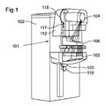
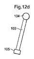
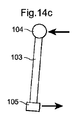
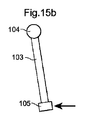
図1は、1つの実施形態によるX線イメージングシステム(101、201、301)を概略的に示し、システムは、X線装置(102、202、302)を有する。X線装置(102、202、302)はさらにスキャンアーム(103、203、303)を有し、X線源(104、204、304)がスキャンアーム(103、203、303)の1つの上方部分(112、212、312)に配置されるが、本発明の他の実施形態にしたがってスキャンアーム(103、203、303)に沿った任意の位置に配置され得る。検出器(105、205、305)がスキャンアーム(103、203、303)の他方の下端に配置され、検出器(105、205、305)は、複数の検出器ストリップ(105a、205a、305a)を有する。しかし、検出器(105、205、305)は、本発明の他の実施形態にしたがってスキャンアーム(103、203、303)に沿った任意の位置に配置され得る。複数のスリット(106a、206a、306a)を有するコリメータ(106、206、306)が、スキャンアーム(103、203、303)上でX線源(104、204、304)と検出器(105、205、305)との間に配置される。装置には、スキャンアーム(103、203、303)及びその任意の運動から分離して、X線装置(102、202、302)はさらに、スキャン中、乳房等、対象(108、208、308)を圧迫し且つ固定するための少なくとも1つの位置調整可能な圧迫パドル(107a、107b;207a、207b;307a、307b)を有する。 FIG. 1 schematically shows an X-ray imaging system (101, 201, 301) according to one embodiment, the system comprising an X-ray device (102, 202, 302). The X-ray apparatus (102, 202, 302) further has a scan arm (103, 203, 303), and the X-ray source (104, 204, 304) is one upper part of the scan arm (103, 203, 303). (112, 212, 312), but can be placed anywhere along the scan arm (103, 203, 303) according to other embodiments of the invention. A detector (105, 205, 305) is disposed at the other lower end of the scan arm (103, 203, 303), and the detector (105, 205, 305) is a plurality of detector strips (105a, 205a, 305a). Have However, the detectors (105, 205, 305) can be placed at any position along the scan arms (103, 203, 303) according to other embodiments of the present invention. A collimator (106, 206, 306) having a plurality of slits (106a, 206a, 306a) is connected to an X-ray source (104, 204, 304) and a detector (105, 205) on the scan arm (103, 203, 303). , 305). The device is separated from the scan arm (103, 203, 303) and any movement thereof, and the X-ray device (102, 202, 302) is further subject to the subject (108, 208, 308), such as the breast, during the scan. At least one adjustable compression paddle (107a, 107b; 207a, 207b; 307a, 307b).
図2は、1つの実施形態によるX線装置(102、202、302)の概略図を示し、2Dスキャン運動及び3Dスキャン運動の両方を可能にする装置の配置及び部品がさらに説明される。図に見られるように、X線源(104、204、304)は第1のサスペンションアーム(109、209、309)の第1の端部に枢動可能に配置される。第1のサスペンションアーム(109、209、309)の第1の端部(109a、209a、309a)は、X線装置の上方部分(112、212、312)に枢動可能に配置され得る。第1のサスペンションアーム(109、209、309)の第2の端部(109b、209b、309b)は、第1(109、209、309)及び第2のサスペンションアーム(110、210、310)の全長が変化され得るような方法で、第2のサスペンションアーム(110、210、310)の第1の端部(110a、210a、310a)に対し直線的に変位可能に配置される。1つの実施形態によれば、第1のサスペンションアーム(109、209、309)は、部分的に第2のサスペンションアーム(110、210、310)の内側に配置されるが、配置は逆にされ得る、すなわち、第2のサスペンションアーム(110、210、310)が、部分的に第1のサスペンションアーム(109、209、309)の内側に配置される。さらに、第2のサスペンションアーム(110、210、310)の第2の端部(110b、210b、310b)が下方部分(111、211、311)に枢動可能に配置される。 FIG. 2 shows a schematic diagram of an X-ray device (102, 202, 302) according to one embodiment, further illustrating the arrangement and components of the device that allow both 2D and 3D scan motions. As can be seen in the figure, the x-ray source (104, 204, 304) is pivotally disposed at the first end of the first suspension arm (109, 209, 309). The first end (109a, 209a, 309a) of the first suspension arm (109, 209, 309) may be pivotally disposed in the upper part (112, 212, 312) of the X-ray device. The second end (109b, 209b, 309b) of the first suspension arm (109, 209, 309) is the same as that of the first (109, 209, 309) and second suspension arm (110, 210, 310). In such a way that the overall length can be changed, it is linearly displaceable with respect to the first end (110a, 210a, 310a) of the second suspension arm (110, 210, 310). According to one embodiment, the first suspension arm (109, 209, 309) is partially placed inside the second suspension arm (110, 210, 310), but the arrangement is reversed. Obtain, i.e., the second suspension arm (110, 210, 310) is partially disposed inside the first suspension arm (109, 209, 309). Further, the second end (110b, 210b, 310b) of the second suspension arm (110, 210, 310) is pivotally disposed on the lower part (111, 211, 311).
水平方向のX線源(104、204、304)の運動を制御するために、第1の直動ネジ(図示せず)がX線装置(102、202、302)に配置され得るととともにX線源(104、204、304)近くの上方部分(112、212、312)の1つの端部に接続され得る。対応する第2の直動ネジ(図示せず)が、水平方向の検出器(105、205、305)の運動を制御するために、下方部分(111、211、311)に配置され得るとともに検出器(105、205、305)に接続され得る。第3の直動ネジ(図示せず)が、第1及び第2のサスペンションアーム(110、210、310)の全長を制御するために、第1及び/又は第2のサスペンションアーム(110、210、310)に配置され得る。しかし、上述の部品間の水平運動を可能にする任意の適切な種類の作動機構が使用され得る。作動機構は、例えば、X線装置の様々な位置に配置された様々なサイズのモータ駆動部を有する。このような作動機構は、図1に概略的に見られるとともに、図20、21及び22に関連してさらに説明もされる。 In order to control the movement of the horizontal X-ray source (104, 204, 304), a first linear screw (not shown) can be placed on the X-ray device (102, 202, 302) and X It can be connected to one end of the upper portion (112, 212, 312) near the source (104, 204, 304). A corresponding second linear screw (not shown) can be placed on the lower part (111, 211, 311) and detected to control the movement of the horizontal detector (105, 205, 305). Can be connected to the device (105, 205, 305). A third linear screw (not shown) controls the first and / or second suspension arms (110, 210) to control the overall length of the first and second suspension arms (110, 210, 310). 310). However, any suitable type of actuation mechanism that allows horizontal movement between the above-described parts may be used. The actuating mechanism has, for example, motor drive units of various sizes arranged at various positions of the X-ray apparatus. Such an actuation mechanism can be seen schematically in FIG. 1 and is further described in connection with FIGS.
第1のサスペンションアーム(109、209、309)に対するスキャンアーム(103、203、303)の回転運動を制御するために、好ましくは電気式の、第1のモータ(116、216、316)が、好ましくは第1のサスペンションアーム(109、209、309)に配置され、第1のスプロケット(117、217、317)が、2つの回転方向の一方の第1のモータ(116、216、316)の作動の際に回転されるように適合される。好ましくは第1のスプロケット(117、217、317)より大きい、第2のスプロケット(118、218、318)が、第1のスプロケット(117、217、317)と噛み合わされるように、スキャンアーム(103、203、303)に配置され、第1のスプロケット(117、217、317)の回転運動が、第2のスプロケット(118、218、318)及びスキャンアーム(103、203、303)に伝達される。好ましくは電気モータであるとともに第1のモータ(116、216、316)と同様の、第2のモータ(126、226、326)が、下方部分(111、211、311)又はX線装置(102、202、302)の他の部分に配置され、第3のスプロケット(119、219、319)が、モータの2つの回転方向の一方の作動の際に回転されるように配置される。好ましくは第3のスプロケット(119、219、319)より大きい、第4のスプロケット(120、220、320)が、第3のスプロケット(119、219、319)と噛み合わされるように、第2のサスペンションアーム(110、210、310)に配置され、第3のスプロケット(119、219、319)の回転運動が、第4のスプロケット(120、220、320)及び第2のサスペンションアーム(110、210、310)に伝達される。制御ユニット(121、221、321)が、モータを、したがって、第1/第2のサスペンションアーム(110、210、310)、及びスキャンアーム(103、203、303)の回転運動を制御するために、モータ(116、216、316、126、226、326)に接続される。この配置を用いて、X線源(104、204、304)及び検出器(105、205、305)の2次元の任意の運動が、スキャンアーム(103、203、303)と第1のサスペンションアーム(109、209、309)との間の回転の限界の、第1及び第2のサスペンションアーム(110、210、310)の全長の変更の、及びX線源(104、204、304)と検出器(105、205、305)との間の接続の機械的な制限の範囲内で可能にされる。スキャンアーム(103、203、303)が存在しない実施形態では、X線源(104、204、304)と検出器(105、205、305)との間の相対運動における追加の自由度が存在する。検出器(105、205、305)及びX線源(104、204、304)がスキャンアーム(103、203、303)によって接続されるとき、X線源(104、204、304)から照射される又は放射されるX線ビーム(126、226、326)はしたがって、検出器(105、205、305)に向けられるように設定される、すなわち、検出器と一直線にされるとともに検出器を照射する又は検出器に放射する。スキャンアーム(103、203、303)が存在せず、X線源(104、204、304)と検出器(105、205、305)との間の絶対距離が変化し得る任意の実施形態では、制御ユニット(121、221、321)が、X線源(104、204、304)から放射されるX線ビームが、検出器(105、205、305)に向けられるとともに検出器(105、205、305)を照射するように適合されるように、X線源(104、204、304)及び検出器(105、205、305)を回転させるように適合される。「照射する」及び「放射する」の語は、明細書を通じて同じ意味で使用される。 To control the rotational movement of the scan arm (103, 203, 303) relative to the first suspension arm (109, 209, 309), preferably a first motor (116, 216, 316), preferably electric, Preferably, the first suspension arm (109, 209, 309) is disposed on the first sprocket (117, 217, 317) of one of the first motors (116, 216, 316) in two rotational directions. Adapted to be rotated in operation. A scan arm (preferably larger than the first sprocket (117, 217, 317), so that a second sprocket (118, 218, 318) is engaged with the first sprocket (117, 217, 317). 103, 203, 303), and the rotational movement of the first sprocket (117, 217, 317) is transmitted to the second sprocket (118, 218, 318) and the scan arm (103, 203, 303). The A second motor (126, 226, 326), which is preferably an electric motor and similar to the first motor (116, 216, 316), is connected to the lower part (111, 211, 311) or X-ray device (102). 202, 302) and the third sprocket (119, 219, 319) is arranged to be rotated during one operation of the motor in two rotational directions. The second sprocket (120, 220, 320), preferably larger than the third sprocket (119, 219, 319), is meshed with the third sprocket (119, 219, 319). The rotational movement of the third sprocket (119, 219, 319) is arranged on the suspension arm (110, 210, 310), and the fourth sprocket (120, 220, 320) and the second suspension arm (110, 210). 310). For the control unit (121, 221, 321) to control the rotational movement of the motor and thus the first / second suspension arm (110, 210, 310) and the scan arm (103, 203, 303) , Connected to motors (116, 216, 316, 126, 226, 326). Using this arrangement, any two-dimensional movement of the X-ray source (104, 204, 304) and detector (105, 205, 305) can be performed by the scan arm (103, 203, 303) and the first suspension arm. Detection of limit of rotation between (109, 209, 309), change of the total length of the first and second suspension arms (110, 210, 310), and X-ray source (104, 204, 304) Within the mechanical limits of the connection between the devices (105, 205, 305). In embodiments where the scan arm (103, 203, 303) is not present, there is an additional degree of freedom in relative motion between the X-ray source (104, 204, 304) and the detector (105, 205, 305). . When the detector (105, 205, 305) and the X-ray source (104, 204, 304) are connected by the scan arm (103, 203, 303), the X-ray source (104, 204, 304) emits light. Or the emitted X-ray beam (126, 226, 326) is therefore set to be directed to the detector (105, 205, 305), ie aligned with and illuminating the detector. Or radiate to the detector. In any embodiment where the scan arm (103, 203, 303) is not present and the absolute distance between the x-ray source (104, 204, 304) and the detector (105, 205, 305) can vary, The control unit (121, 221, 321) directs the X-ray beam emitted from the X-ray source (104, 204, 304) to the detector (105, 205, 305) and the detector (105, 205, 305). The X-ray source (104, 204, 304) and the detector (105, 205, 305) are adapted to rotate so as to be adapted to irradiate 305). The terms “irradiate” and “radiate” are used interchangeably throughout the specification.
対象に対するX線源(104、204、304)及び検出器(105、205、305)のスキャン運動中、X線源(104、204、304)はこのように、時間内の任意の瞬間おいて及び異なるスキャンの間で再定義され得る、考えられた、任意の第1の運動経路に沿って動かされ得る、並びに、この運動中に回転され得る。同様の方法で、検出器(105、205、305)は、時間内の任意の瞬間において及び異なるスキャンの間で再定義され得る、考えられた、任意の第2の運動経路に沿って動かされ得る、並びに、この運動中に回転され得る。さらに、この明細書を通じて、スキャン運動は、第1及び第2の運動経路に沿ったX線源(104、204、304)及び/又は検出器(105、205、305)組立体の運動と見なされる。スキャン運動はさらに、対象の画像が再構成されることができる照射された放射線が実際に対象(108、208、308)に衝突しているとき、サブセットを有する。このような運動は、以下、対象のスキャン、又は代替的に、対象スキャンと称される。スキャン運動は、画像ボリュームの再構成、すなわち、トモシンセシス用画像又は少なくとも対象の画像ボリュームのスライス、に必要なX線源及び検出器の運動を含み得る。このようなスキャン運動は、対象の同じポイントを通る様々な投影角度、いわゆる切断角度、又は断層撮影角度若しくは断層撮影投影角度を有するスキャン運動を必要とし、それらの広がりはしばしば断層振角と称され、この断層振角は垂直解像度と関連する。これらの角度は、画像領域にわたって変化することができ、それによって取得される3D画像は、特性における局所的な変動を有し得る。1つの実施形態によれば、スキャン運動はさらに、X線源がX線画像を生成する目的でX線ビームを検出器に向かって放射することを含む。 During the scanning movement of the X-ray source (104, 204, 304) and detector (105, 205, 305) with respect to the object, the X-ray source (104, 204, 304) is thus at any instant in time. And can be redefined between different scans, can be moved along any considered first motion path, and can be rotated during this motion. In a similar manner, the detectors (105, 205, 305) are moved along any conceivable second motion path that can be redefined at any moment in time and between different scans. As well as being rotated during this movement. Further, throughout this specification, scanning motion is considered motion of the x-ray source (104, 204, 304) and / or detector (105, 205, 305) assembly along the first and second motion paths. It is. The scanning motion further has a subset when the irradiated radiation that can be reconstructed of the object is actually impinging on the object (108, 208, 308). Such movement is hereinafter referred to as a subject scan, or alternatively a subject scan. Scanning motion may include X-ray source and detector motion necessary for reconstruction of the image volume, i.e., tomosynthesis image or at least a slice of the image volume of interest. Such scanning movements require scanning movements with various projection angles through the same point of interest, so-called cutting angles, or tomographic or tomographic projection angles, and their spread is often referred to as tomographic angle. This fault angle is related to the vertical resolution. These angles can vary across the image area, and the 3D images acquired thereby can have local variations in properties. According to one embodiment, the scanning motion further includes the X-ray source emitting an X-ray beam toward the detector for the purpose of generating an X-ray image.
図3には、スキャンアーム(103、203、303)の可能な位置の例、したがって、検出器(105、205、305)に対するX線源(104、204、304)の関係の例を示し、上述の構成を用いて、X線源(104、204、304)及び検出器(105、205、305)の運動を制御する。第1及び第2の直動ネジ(図示せず)は、検出器(105、205、305)並びにX線源(104、204、304)を図3の右の部分に動かす。さらに、第3の直動ネジ(115、215、315)の作動は、第1及び第2のサスペンションアーム(110、210、310)の全長を増加させ、X線源(104、204、304)は、上方の位置に且つ図の右に動かされる。当然、同じ運動が、第1及び第2のサスペンションアーム(110、210、310)の直動ネジと組み合わせたスプロケット1−4の作動によって達成され得る。 FIG. 3 shows an example of possible positions of the scan arm (103, 203, 303) and thus an example of the relationship of the X-ray source (104, 204, 304) to the detector (105, 205, 305), The above-described configuration is used to control the movement of the X-ray source (104, 204, 304) and detector (105, 205, 305). First and second linear screws (not shown) move the detector (105, 205, 305) and the X-ray source (104, 204, 304) to the right part of FIG. Further, the operation of the third linear screw (115, 215, 315) increases the overall length of the first and second suspension arms (110, 210, 310), and the X-ray source (104, 204, 304). Is moved to an upper position and to the right of the figure. Of course, the same movement can be achieved by operation of the sprocket 1-4 in combination with the linear motion screws of the first and second suspension arms (110, 210, 310).
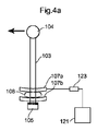
図4aは、位置調整可能な圧迫パドル(107a、107b;207a、207b;307a、307b)及び位置(123、223、323)、好ましくは、空間内の固定点に対する圧迫パドル(107a、107b;207a、207b;307a、307b)の高さ位置、を測定するための手段を有する、本発明の実施形態を示す。圧迫パドル(107a、107b;207a、207b;307a、307b)の位置(123、223、323)を測定するための手段は、X線源(104、204、304)及び検出器(105、205、305)の運動を制御するための制御ユニット(121、221、321)に、例えば、ケーブル(124、224、324)を介して又は無線伝送を介して、接続される。圧迫パドル(107a、107b;207a、207b;307a、307b)の位置(123、223、323)を測定するための手段は、圧迫パドル(107a、107b;207a、207b;307a、307b)の位置に対応するデータを制御ユニット(121、221、321)に出力するように適合される。制御ユニット(121、221、321)は、この出願を通して外部データとも称されるこのようなデータを受信するように適合され、制御ユニット(121、221、321)は、この外部データに基づいて、X線源(104、204、304)及び検出器(105、205、305)の運動を制御するように適合される。 FIG. 4a shows an adjustable compression paddle (107a, 107b; 207a, 207b; 307a, 307b) and position (123, 223, 323), preferably a compression paddle (107a, 107b; 207a) relative to a fixed point in space. 207b; 307a, 307b), the embodiment of the present invention having means for measuring. Means for measuring the position (123, 223, 323) of the compression paddles (107a, 107b; 207a, 207b; 307a, 307b) include an X-ray source (104, 204, 304) and a detector (105, 205, 305) is connected to a control unit (121, 221, 321) for controlling the movement, for example via cables (124, 224, 324) or via wireless transmission. Means for measuring the position (123, 223, 323) of the compression paddles (107a, 107b; 207a, 207b; 307a, 307b) are located at the positions of the compression paddles (107a, 107b; 207a, 207b; 307a, 307b). It is adapted to output corresponding data to the control unit (121, 221, 321). The control unit (121,221,321) is adapted to receive such data, also referred to as external data throughout this application, and the control unit (121,221,321) is based on this external data, It is adapted to control the movement of the X-ray source (104, 204, 304) and detector (105, 205, 305).
どのように制御ユニット(121、221、321)がX線源(104、204、304)の運動を制御するかの1つの例は、図4a及び図4bの例に見ることができる。図4aの実施形態によれば、対象(108、208、308)のスキャンが開始され、少なくともX線源(104、204、304)は、圧迫パドル(107a、107b;207a、207b;307a、307b)の位置に基づいて制御ユニット(121、221、321)によって定められた速度vで移動する。図4bでは、圧迫パドル(107a、107b;207a、207b;307a、307b)は、4aのものより高い位置を有し、制御ユニット(121、221、321)は、スキャン中、少なくともX線源(104、204、304)のより低い速度を設定する。したがって、制御ユニット(121、221、321)は、圧迫パドル(107a、107b;207a、207b;307a、307b)が圧迫パドルの他の低い位置に比べて比較的高い場合、X線源(104、204、304)のより低い速度を設定するように適合される。 One example of how the control unit (121, 221, 321) controls the movement of the X-ray source (104, 204, 304) can be seen in the examples of FIGS. 4a and 4b. According to the embodiment of FIG. 4a, a scan of the object (108, 208, 308) is started and at least the X-ray source (104, 204, 304) is compressed with paddles (107a, 107b; 207a, 207b; 307a, 307b). ) At a speed v determined by the control unit (121, 221 and 321) based on the position of). In FIG. 4b, the compression paddles (107a, 107b; 207a, 207b; 307a, 307b) have a higher position than that of 4a, and the control unit (121, 221, 321) is at least an X-ray source ( 104, 204, 304). Thus, the control unit (121, 221, 321) may be used when the compression paddles (107a, 107b; 207a, 207b; 307a, 307b) are relatively high compared to other low positions of the compression paddles (104, 204, 304) adapted to set a lower speed.
1つの実施形態によれば、X線源(104、204、304)及び検出器(105、205、305)がそれらの第1及び第2の運動経路に沿ってそれぞれの速度で動く場合、制御ユニット(121、221、321)は、X線源(104、204、304)及び検出器(105、205、305)の速度の間の比が、少なくとも対象のスキャン中、X線源(104、204、304)が検出器(105、205、305)を水平方向に通過することを可能にするように十分高くなるよう、X線源(104、204、304)の速度を制御するように適合される。 According to one embodiment, if the X-ray source (104, 204, 304) and detector (105, 205, 305) move at their respective speeds along their first and second motion paths, control The units (121, 221 and 321) have a ratio between the speed of the X-ray source (104, 204, 304) and the detector (105, 205, 305) so that the X-ray source (104, 204, 304) adapted to control the speed of the X-ray source (104, 204, 304) to be high enough to allow the detector (105, 205, 305) to pass horizontally. Is done.
図5a及び図5bには、本発明のさらなる態様が示される。制御ユニット(121、221、321)は、検出器(105、205、305)と圧迫パドル(107a、107b;207a、207b;307a、307b)との間の衝突が防がれるように、少なくとも1つの圧迫パドル(107a、107b;207a、207b;307a、307b)の位置を含む外部データからの入力に基づいて、X線源(104、204、304)及び検出器(105、205、305)の運動を制御するように適合される。したがって、第2の運動経路が圧迫パドル(107a、107b;207a、207b;307a、307b)の位置を横切らないとき、すなわち、圧迫パドル(107a、107b;207a、207b;307a、307b)が第2の運動経路の外にあるとき、衝突は回避される。図5aでは、第1及び第2の運動経路の一部が示され、下方圧迫パドル(107a、107b;207a、207b;307a、307b)は第2の運動経路の外側にあり、衝突は回避される。図5bは、反対に、X線源(104、204、304)及び検出器(105、205、305)の運動の許されない制御を示し、圧迫パドル(107a、107b;207a、207b;307a、307b)は、第2の運動経路の妨げになり、最終的に衝突が起こる。 5a and 5b show a further aspect of the present invention. The control unit (121, 221, 321) has at least 1 so that a collision between the detector (105, 205, 305) and the compression paddle (107a, 107b; 207a, 207b; 307a, 307b) is prevented. Based on input from external data including the position of the two compression paddles (107a, 107b; 207a, 207b; 307a, 307b), the X-ray source (104, 204, 304) and the detector (105, 205, 305) Adapted to control movement. Accordingly, when the second movement path does not cross the position of the compression paddle (107a, 107b; 207a, 207b; 307a, 307b), that is, the compression paddle (107a, 107b; 207a, 207b; 307a, 307b) Collisions are avoided when outside the path of motion. In FIG. 5a, a portion of the first and second movement paths are shown, and the lower compression paddles (107a, 107b; 207a, 207b; 307a, 307b) are outside the second movement paths and collisions are avoided. The FIG. 5b, conversely, shows unacceptable control of the movement of the X-ray source (104, 204, 304) and detector (105, 205, 305), and compression paddles (107a, 107b; 207a, 207b; 307a, 307b). ) Interferes with the second path of motion and eventually a collision occurs.
図6a及び図6bは、コリメータ(106、206、306)の追加の僅かな違いを持つ図5a及び5bと類似の構成を示す。制御ユニット(121、221、321)は、コリメータ(106、206、306)と圧迫パドル(107a、107b;207a、207b;307a、307b)との間の衝突が回避されるように、少なくとも1つの圧迫パドル(107a、107b;207a、207b;307a、307b)の位置を含む外部データからの入力に基づいて、X線源(104、204、304)及び検出器(105、205、305)の運動を制御するように適合される。X線源(104、204、304)及び検出器(105、205、305)の定められた運動経路と類似して、コリメータ(106、206、306)は、第1及び第2の運動経路によって定められる第3の運動経路に追って動く。したがって、第3の運動経路が圧迫パドル(107a、107b;207a、207b;307a、307b)の位置を横切らないとき、すなわち、圧迫パドル(107a、107b;207a、207b;307a、307b)が第3の運動経路の外にあるとき、衝突は回避される。図6aでは、第1、第2及び第3の運動経路の一部が示され、圧迫パドル(107a、107b;207a、207b;307a、307b)は第3の運動経路の外側にあり、衝突は回避される。図6bは、反対に、X線源(104、204、304)及び検出器(105、205、305)の運動の許されない制御を示し、上方の圧迫パドル(107a、107b;207a、207b;307a、307b)は、第3の運動経路の妨げになり、最終的に衝突が起こる。 Figures 6a and 6b show a similar configuration to Figures 5a and 5b with the additional slight difference of the collimators (106, 206, 306). The control unit (121, 221, 321) includes at least one so that a collision between the collimator (106, 206, 306) and the compression paddle (107a, 107b; 207a, 207b; 307a, 307b) is avoided. X-ray source (104, 204, 304) and detector (105, 205, 305) motion based on input from external data including the position of compression paddles (107a, 107b; 207a, 207b; 307a, 307b) Adapted to control. Similar to the defined motion path of the X-ray source (104, 204, 304) and detector (105, 205, 305), the collimator (106, 206, 306) is driven by the first and second motion paths. It moves following a third movement path that is defined. Therefore, when the third movement path does not cross the position of the compression paddle (107a, 107b; 207a, 207b; 307a, 307b), that is, the compression paddle (107a, 107b; 207a, 207b; 307a, 307b) Collisions are avoided when outside the path of motion. In FIG. 6a, part of the first, second and third movement paths are shown, the compression paddles (107a, 107b; 207a, 207b; 307a, 307b) are outside the third movement path and the collision is Avoided. FIG. 6b, conversely, shows unacceptable control of the movement of the X-ray source (104, 204, 304) and detector (105, 205, 305), with the upper compression paddles (107a, 107b; 207a, 207b; 307a). 307b) hinders the third movement path and eventually a collision occurs.
図7aでは、本発明によるX線装置(102、202、302)を用いて可能な他の種類のスキャン運動を示す。ここでは、垂直線に対するスキャンアーム(103、203、303)の角度αが、全てのスキャン運動中に本質的に不変である。角度αは、圧迫パドル(107a、107b;207a、207b;307a、307b)の高さ位置を考慮して、制御ユニット(121、221、321)によってスキャン運動の開始中に設定され、角度αは、パドル及び患者サポートの形状に依存して、大まかに前記高さ位置に反比例する。図7bに見られるように、スキャンアーム(103、203、303)の角度αは、制御ユニット(121、221、321)が圧迫パドル(107a、107b;207a、207b;307a、307b)の高い位置を検出するとき、スキャン運動に関して制御ユニット(121、221、321)によって小さく設定される。これによって、コリメータ(106、206、306)と圧迫パドル(107a、107b;207a、207b;307a、307b)との間の望まれない衝突が回避される。他の実施形態では、制御ユニット(121、221、321)は、スキャンアーム(103、203、303)の角度αが制限値を超えないように、X線源(104、204、304)及び検出器(105、205、305)の運動を制御するように適合され、制限値は、第1の運動経路に沿ったX線源(104、204、304)の位置及び第2の運動経路に沿った検出器(105、205、305)の位置によって並びに圧迫パドル(107a、107b;207a、207b;307a、307b)の高さ位置に基づいて、絶えず変化している。例えば、圧迫パドル(107a、107b;207a、207b;307a、307b)の高い位置に起因して小さい角度αを可能にするスキャンアーム(103、203、303)の一般的な制御に加えて、スキャンアーム(103、203、303)の比較的高い位置は、スキャンアーム(103、203、303)の比較的低い位置より、多少大きい角度を可能にし、コリメータ(106、206、306)と圧迫パドル(107a、107b;207a、207b;307a、307b)との間の衝突は依然として回避される。 FIG. 7a shows another type of scanning motion possible using the X-ray device (102, 202, 302) according to the invention. Here, the angle α of the scan arm (103, 203, 303) with respect to the vertical line is essentially unchanged during all scanning movements. The angle α is set by the control unit (121, 221 and 321) during the start of the scanning movement, taking into account the height position of the compression paddles (107a, 107b; 207a, 207b; 307a, 307b), and the angle α is Depending on the shape of the paddle and patient support, it is roughly inversely proportional to the height position. As can be seen in FIG. 7b, the angle α of the scan arm (103, 203, 303) is such that the control unit (121, 221, 321) is at a high position of the compression paddle (107a, 107b; 207a, 207b; 307a, 307b). Is detected by the control unit (121, 221, 321) with respect to the scanning motion. This avoids unwanted collisions between the collimator (106, 206, 306) and the compression paddle (107a, 107b; 207a, 207b; 307a, 307b). In other embodiments, the control unit (121, 221 and 321) may detect the X-ray source (104, 204, 304) and the detection so that the angle α of the scan arm (103, 203, 303) does not exceed the limit value. Adapted to control the movement of the device (105, 205, 305), the limit values being along the position of the X-ray source (104, 204, 304) along the first movement path and the second movement path. Continuously changing depending on the position of the detector (105, 205, 305) and the height of the compression paddle (107a, 107b; 207a, 207b; 307a, 307b). For example, in addition to the general control of the scan arm (103, 203, 303) that allows a small angle α due to the high position of the compression paddles (107a, 107b; 207a, 207b; 307a, 307b) The relatively high position of the arms (103, 203, 303) allows a slightly larger angle than the relatively low position of the scan arms (103, 203, 303), and the collimator (106, 206, 306) and the compression paddle ( 107a, 107b; 207a, 207b; 307a, 307b) are still avoided.
本発明の他の実施形態によれば、検出器(105、205、305)は、全スキャン運動中にリアルタイムでX線源(104、204、304)からの入射されたX線ビーム(122、222、322)の特性を感知するように適合される。検出器(105、205、305)はさらに、前記データを出力するように適合され、X線源(104、204、304)及び検出器(105、205、305)の運動を制御する制御ユニット(121、221、321)は、例えばケーブル(124、224、324)又は無線伝送によって検出器(105、205、305)に接続され、外部データとも呼ばれる、前記データは、制御ユニット(121、221、321)によって受信され、制御ユニット(121、221、321)は、残りのスキャン運動を制御するために前記外部データを使用する。 According to another embodiment of the present invention, the detector (105, 205, 305) is configured to detect the incident X-ray beam (122, 304) from the X-ray source (104, 204, 304) in real time during the entire scan motion. 222, 322). The detector (105, 205, 305) is further adapted to output said data and a control unit (controlling the movement of the X-ray source (104, 204, 304) and detector (105, 205, 305). 121, 221, 321) are connected to the detectors (105, 205, 305) by, for example, cables (124, 224, 324) or wireless transmission and are also called external data, 321), the control unit (121, 221, 321) uses the external data to control the remaining scanning motion.
図8aに見られるように、検出器(105、205、305)は、第1の端部(105b、205b、305b)及び第2の端部(105c、205c、305c)を有し、複数の検出器ライン(125)が前記第1と第2の端部との間に配置される。検出器(105、205、305)は、スキャン運動中のX線源(104、204、304)からの衝突光子をうけるように適合され、検出器(105、205、305)はさらに、各衝突光子のエネルギに対応する信号を発生させることによって、特定のエネルギ閾値を超える検出器(105、205、305)に衝突する各光子をカウントするように適合される。対象のスキャン中、より少ない数の前記閾値を超えるタイムフレーム毎の衝突光子が、スキャンされるためにX線ビームに置かれる対象(108、208、308)がX線ビームからの光子を減衰させないときの残りのスキャン運動に比べて、検出器(105、205、305)に到達する。言い換えると、光子のX線強度、又はカウントレートは、残りのスキャン運動と比べて、いったん対象(108、208、308)のスキャンが始まると、低くなる。X線強度を確認する又は検出する他の方法、例えば、タイムフレーム中の総計の電荷の読み出しを測定すること等も、技術分野で知られている。この実施形態によれば、このような情報は、X線源(104、204、304)及び検出器(105、205、305)の運動を制御するために、制御ユニット(121、221、321)によって使用される。同じ図では、X線源(104、204、304)及び検出器(105、205、305)のスキャン運動が、2つの圧迫パドル(107a、107b;207a、207b;307a、307b)の間で圧迫される対象(108、208、308)が見られることと並んで、示され、スキャンアーム(103、203、303)は、ある速度で左に動く。図示されたスキャン運動は、つい最近対象のスキャンになった。スキャン運動のこの段階は、検出器ライン(105a、205a、305a)が対象の光子の減衰に起因する低いカウントレートを感知するとき、本質的に検出器(105、205、305)の左の部分に配置される検出器(105、205、305)の第1の端部の近くに配置される検出器ライン(105a、205a、305a)によって感知される。この情報、又はデータは、残りのスキャン運動を制御するために、制御ユニット(121、221、321)に送られる。図8bに見られるように、1つの実施形態によれば、少なくともX線源(104、204、304)の速度はその結果、対象(108、208、308)の残りのスキャンの間に、検出器(105、205、305)によって感知される実際のカウントレートに関連している予め設定された速度に減少する。本質的に、X線源の速度は、対象のスキャン中、X線源よりも減少するので、X線源の速度と検出器の速度との間の高い比が達成される。これによって、対象の各ポイントに対する断層振角が増加し、これは関連する対象に対するトモシンセシス画像を再構成するときに関係する。同時に、対象のスキャンではないスキャン運動中にX線源及び検出器の高い速度を有することを可能にすることによって、全スキャン運動を行うための時間が減少する。これは、マンモグラフィスクリーニング中に実行される必要がある大量の調査を考慮するとき、少なから利益がある。感知されたカウントレートと速度との間の関係に関するデータは、表形式で、制御ユニット(121、221、321)の又は制御ユニットに接続されたメモリデバイスに保存され得るとともに、運動を制御する際、制御ユニット(121、221、321)によって使用される。対象のスキャンではないスキャン運動の任意の部分において、スキャンを実行するために必要な時間を低減させるために、少なくともX線源の速度が対象(108、208、308)のスキャン前に再び増加され得る。さらに、制御ユニット(121、221、321)は、X線源(104、204、304)及び検出器(105、205、305)の運動を、それらのそれぞれの速度の間の比が、検出器(105、205、305)によって感知される対象(108、208、308)のスキャン中、X線源(104、204、304)が検出器(105、205、305)を水平方向に通過することを可能にするよう十分高くなるように、制御する。 As seen in FIG. 8a, the detector (105, 205, 305) has a first end (105b, 205b, 305b) and a second end (105c, 205c, 305c), and a plurality of A detector line (125) is disposed between the first and second ends. The detector (105, 205, 305) is adapted to receive impact photons from the x-ray source (104, 204, 304) during the scanning motion, and the detector (105, 205, 305) further includes By generating a signal corresponding to the energy of the photons, it is adapted to count each photon that strikes a detector (105, 205, 305) that exceeds a certain energy threshold. During scanning of an object, a smaller number of collision photons per time frame that exceed the threshold are placed in the x-ray beam to be scanned (108, 208, 308) do not attenuate photons from the x-ray beam Compared to the remaining scan motion at the time, the detector (105, 205, 305) is reached. In other words, the photon x-ray intensity, or count rate, is low once the scan of the object (108, 208, 308) has begun compared to the rest of the scanning motion. Other methods of confirming or detecting x-ray intensity are also known in the art, such as measuring the total charge readout during a time frame. According to this embodiment, such information is used to control the movement of the X-ray source (104, 204, 304) and detector (105, 205, 305) in the control unit (121, 221 and 321). Used by. In the same figure, the scanning motion of the X-ray source (104, 204, 304) and detector (105, 205, 305) is compressed between two compression paddles (107a, 107b; 207a, 207b; 307a, 307b). The scan arm (103, 203, 303) moves to the left at a certain speed, shown alongside the object (108, 208, 308) being viewed. The scan motion shown has recently become the subject scan. This stage of the scan motion is essentially the left part of the detector (105, 205, 305) when the detector line (105a, 205a, 305a) senses a low count rate due to the attenuation of the photons of interest. Is sensed by a detector line (105a, 205a, 305a) located near the first end of the detector (105, 205, 305). This information, or data, is sent to the control unit (121, 221, 321) to control the remaining scanning motion. As seen in FIG. 8b, according to one embodiment, at least the speed of the x-ray source (104, 204, 304) is consequently detected during the remaining scans of the object (108, 208, 308). Decrease to a preset speed that is related to the actual count rate sensed by the device (105, 205, 305). In essence, the speed of the x-ray source is reduced over the x-ray source during the scan of the object, so that a high ratio between the x-ray source speed and the detector speed is achieved. This increases the tomographic angle for each point of interest, which is relevant when reconstructing tomosynthesis images for the relevant subject. At the same time, by allowing the X-ray source and detector to have a high velocity during a scan motion that is not the subject scan, the time to perform the full scan motion is reduced. This is of little benefit when considering the large amount of research that needs to be performed during mammography screening. Data relating to the relationship between the sensed count rate and speed can be stored in a tabular format in a memory device of the control unit (121, 221, 321) or connected to the control unit and in controlling the movement. Used by the control unit (121, 221, 321). In any part of the scan movement that is not the scan of the subject, at least the x-ray source speed is increased again before the scan of the subject (108, 208, 308) to reduce the time required to perform the scan. obtain. In addition, the control unit (121, 221 and 321) is adapted to determine the motion of the X-ray source (104, 204, 304) and detector (105, 205, 305), the ratio between their respective velocities. During scanning of the object (108, 208, 308) sensed by (105, 205, 305), the X-ray source (104, 204, 304) passes horizontally through the detector (105, 205, 305). Control to be high enough to allow
本発明の他の実施形態によれば、図9に見られるように、制御ユニット(121、221、321)はさらに、対象の関心領域、例えば、乳房の疑わしい異常を識別する検出器(105、205、305)に基づいて、X線源(104、204、304)及び検出器(105、205、305)の運動を制御するように適合され、ある予め定められたスキャン運動が実行される、又は少なくともX線源(104、204、304)の速度が、この領域のさらに分析する能力を高めるために、減少する。関心領域は、対象(108、208、308)の暗点として見られる。この識別は、対象の実際のスキャン中に行われ得るが、直接事前に前のスキャン中に、又は代替的に、対象の関心領域が識別された時に異なるスクリーニングにおいて、実行されてもよい。この領域だけに対するスキャン運動を実行するためのX線源及び検出器の位置は、これらの予め定められた位置に対応するデータの保存を必要とする。後者の場合、制御ユニット(121、221、321)によって使用される外部データは、データベースに保存されることができ、このデータベースは制御ユニット(121、221、321)によってアクセス可能である。関心点に対して実行されるこれらの種類のスキャンは通常、スポットスキャンと呼ばれる。1つの実施形態によれば、X線源(104、204、304)及び検出器(105、205、305)は、関心領域に到達するとき、X線源の速度と検出器(105、205、305)の速度との間の比が、より大きい断層振角が達成されるように増加するような方法で、それらの両方の速度を減少させる。 According to another embodiment of the present invention, as seen in FIG. 9, the control unit (121, 221, 321) further includes a detector (105, 205, 305) is adapted to control the movement of the X-ray source (104, 204, 304) and detector (105, 205, 305), and a predetermined scanning movement is performed. Or at least the speed of the x-ray source (104, 204, 304) is decreased to increase the ability of this region to further analyze. The region of interest is seen as the dark spot of the object (108, 208, 308). This identification may be performed during the actual scan of the subject, but may be performed directly prior to the previous scan, or alternatively in a different screening when the region of interest of the subject is identified. The position of the x-ray source and detector to perform the scanning motion only for this region requires the storage of data corresponding to these predetermined positions. In the latter case, external data used by the control unit (121, 221 and 321) can be stored in a database, which can be accessed by the control unit (121, 221 and 321). These types of scans performed on points of interest are usually referred to as spot scans. According to one embodiment, the X-ray source (104, 204, 304) and detector (105, 205, 305), when reaching the region of interest, the velocity of the X-ray source and the detector (105, 205, 305). 305) reduce the speed of both of them in such a way that the ratio between them increases so that a greater fault angle is achieved.
対象(108、208、308)がスキャンされるときに感知するための検出器(105、205、305)の能力に関して上述されていることは、圧迫パドルの存在に基づく運動の制御に関連して記載された実施形態のいずれかに実装されることができるとともに同実施形態のいずれかとともに使用されることができる。 What has been described above regarding the ability of the detector (105, 205, 305) to sense when the object (108, 208, 308) is scanned is related to the control of movement based on the presence of a compression paddle. It can be implemented in any of the described embodiments and can be used with any of the embodiments.
以下では、異なるスキャン運動が記載され、このスキャン運動は、幾つかの実施形態にしたがって、外部データに基づいて切断角度を最適化する働きをし得る。 In the following, different scanning movements are described, which scanning movements may serve to optimize the cutting angle based on external data according to some embodiments.
図10a―10eは、X線源(104、204、304)及び検出器(105、205、305)を有するスキャンアーム(103、203、303)並びに1つの好適なスキャン運動の概略図を示す。矢印の方向及びサイズは、X線源(104、204、304)及び検出器(105、205、305)の方向及び速度を示す。矢印の欠如は、X線源又は検出器のゼロ速度を示す。X線源及び検出器の変向点は、X線源又は検出器が第1から第2の方向に変わる位置を含み、第2の方向は本質的に第1の方向の反対である。図10aでは、X線源(104、204、304)及び検出器(105、205、305)の両方が第1の変向点に向かって移動し、X線源(104、204、304)は、検出器(105、205、305)と異なる速度を有する、すなわち、X線源(104、204、304)の速度と検出器(105、205、305)の速度との間の比が約2である。図10bでは、X線源(104、204、304)は、高い速度のために、水平方向に検出器(105、205、305)を通過している。図10cでは、X線源(104、204、304)は、第1の運動経路に沿って第1の変向点に到達しており、検出器(105、205、305)は、第2の運動経路に沿って第1の変向点に向かう運動を続けている。図10dでは、X線源(104、204、304)は、本質的に、変向点に到達する前と反対方向に向きを変え、X線源(104、204、304)の速度は、変向点に到達する前に有していたのと同様の速度に、本質的に転向後即座に、増加される。これは、X線源(104、204、304)の比較的高い加速度を必要とし、1つの実施形態によれば、加速度は約1m/s2である。同じスキャンにおいて、X線源(104、204、304)及び検出器(105、205、305)は、第1及び第2の運動経路に沿って第2の変向点に向かって移動し得るとともに上述のように対応する運動を実行し得る。 Figures 10a-10e show a schematic diagram of a scan arm (103, 203, 303) with an x-ray source (104, 204, 304) and a detector (105, 205, 305) and one suitable scan motion. The direction and size of the arrows indicate the direction and speed of the X-ray source (104, 204, 304) and detector (105, 205, 305). The lack of an arrow indicates the zero velocity of the x-ray source or detector. The turning point of the x-ray source and detector includes a position where the x-ray source or detector changes from a first direction to a second direction, the second direction being essentially the opposite of the first direction. In FIG. 10a, both the X-ray source (104, 204, 304) and the detector (105, 205, 305) are moved toward the first turning point, and the X-ray source (104, 204, 304) is Have a different speed than the detector (105, 205, 305), ie the ratio between the speed of the X-ray source (104, 204, 304) and the speed of the detector (105, 205, 305) is about 2 It is. In FIG. 10b, the x-ray sources (104, 204, 304) are passing through the detectors (105, 205, 305) in the horizontal direction due to the high speed. In FIG. 10c, the X-ray source (104, 204, 304) has reached the first turning point along the first motion path, and the detector (105, 205, 305) The movement toward the first turning point is continued along the movement path. In FIG. 10d, the X-ray source (104, 204, 304) is essentially turned in the opposite direction as before it reached the turning point, and the speed of the X-ray source (104, 204, 304) is changed. It is increased to a speed similar to that it had before reaching the turning point, essentially immediately after turning. This requires a relatively high acceleration of the x-ray source (104, 204, 304), and according to one embodiment, the acceleration is about 1 m / s 2 . In the same scan, the x-ray source (104, 204, 304) and detector (105, 205, 305) may move along the first and second motion paths toward the second turning point. A corresponding movement may be performed as described above.
図10eは、図10a−10dのスキャン運動を示し、達成される切断角度が示されている。第1の運動経路に沿ったX線源の運動及び第2の運動経路に沿った検出器の運動は、組み合わされた運動経路に対応し、前記組み合わされた運動経路は、図に見られるように、1つの軸に沿った位置及び前記X線源と検出器との間の角度を含む、多次元パラメータ空間を通る曲線によって示されることができる。3つの点(125)は、検出器(105、205、305)の3つの検出器ライン(125)に対応する、したがって3つの異なる角度で検出器(105、205、305)に衝突する、3つのX線の束の位置を示し、中央の線は、角度=0で検出器(105、205、305)と衝突する。スキャンされている対象(108、208、308)に沿った位置は、X軸によって表される。検出器(105、205、305)に衝突する3つの示された線の中央の線に対応する垂直線に対するX線源(104、204、304)及び検出器(105、205、305)の変化する線の角度が、y軸vrに沿って示され、したがって、黙示的に検出器(105、205、305)に対するX線源(104、204、304)の位置を示す。X線検出器(105、205、305)の2つの位置の間のスキャン運動中に達成される切断角度は、距離vt、すなわち、ローカル断層撮影角度の広がりによって表される。 FIG. 10e shows the scanning motion of FIGS. 10a-10d, showing the cutting angle achieved. The movement of the X-ray source along the first movement path and the movement of the detector along the second movement path correspond to a combined movement path, which can be seen in the figure. Can be represented by a curve through a multidimensional parameter space, including the position along one axis and the angle between the x-ray source and the detector. The three points (125) correspond to the three detector lines (125) of the detectors (105, 205, 305) and thus impinge on the detectors (105, 205, 305) at three different angles. The position of two X-ray bundles is shown, the middle line collides with the detector (105, 205, 305) at angle = 0. The position along the object being scanned (108, 208, 308) is represented by the X axis. Changes in X-ray source (104, 204, 304) and detector (105, 205, 305) relative to a vertical line corresponding to the middle line of the three shown lines impinging on the detector (105, 205, 305) angle of the line to be is shown along the y-axis v r, thus indicating the position of implicitly detector X-ray source for (105, 205, 305) (104, 204, 304). The cutting angle achieved during the scanning movement between the two positions of the X-ray detector (105, 205, 305) is represented by the distance vt, ie the spread of the local tomographic angle.
3つの点(125)の左の最下位置、すなわち第3象限にある、は図5aに対応し、検出器(105、205、305)は、対象の左の部分をスキャンする検出器(105、205、305)の僅かに左にある。第2象限の3つの検出器ラインの位置は、スキャンアーム(103、203、303)の位置を表し、図10cに示されるもの、すなわち、X線源が変向点に到達するとき、に対応する。図10bは、今記載したものとX軸との間の位置に対応する。図10dは、vrがゼロであり且つ対象(108、208、308)の中央がスキャンされる原点の位置に対応する。対象の右部分に向かう継続するスキャン運動は、第1象限及び第4象限の点(125)によって表される。スキャン運動のこの部分は、それがちょうど記載した運動の鏡映であるので、ここではさらに説明されない。図10eから、切断角度に対するX線源(104、204、304)の速度と検出器(105、205、305)の速度との間の比の重要性が理解される。比が高くなるほど、したがって、検出器(105、205、305)の2つの位置の間の線の急峻さが高くなるほど、大きい切断角度が達成される。したがって、X線源(104、204、304)が鋭く加速される、X線源が転向する直度のスキャン運動は、大きく且つ最適化された切断角度を実現するために不可欠である。 The left bottom position of the three points (125), ie in the third quadrant, corresponds to FIG. 5a, and the detector (105, 205, 305) is a detector (105 that scans the left part of the object). 205, 305) slightly to the left. The positions of the three detector lines in the second quadrant represent the positions of the scan arms (103, 203, 303) and correspond to those shown in FIG. 10c, ie when the X-ray source reaches the turning point. To do. FIG. 10b corresponds to the position between what has just been described and the X axis. Figure 10d is, v r corresponds to the position of the origin the center is scanned is and object (108, 208, 308) is zero. The continuing scanning movement towards the right part of the subject is represented by points (125) in the first and fourth quadrants. This part of the scan motion is not further described here because it is just a reflection of the motion just described. From FIG. 10e, the importance of the ratio between the speed of the X-ray source (104, 204, 304) and the speed of the detector (105, 205, 305) relative to the cutting angle is understood. The higher the ratio, and thus the higher the steepness of the line between the two positions of the detector (105, 205, 305), the greater the cutting angle is achieved. Thus, a straight scan motion in which the X-ray source turns, where the X-ray source (104, 204, 304) is sharply accelerated is essential to achieve a large and optimized cutting angle.
図11a−11dは、図10a−10dに記載されたものと同様のスキャン運動を示し、検出器(105、205、305)が、X線源(104、204、304)より前に第1の変向点に到達するという違いがある。したがって、スキャン運動は、ここではさらに説明されない。 FIGS. 11a-11d show a scanning motion similar to that described in FIGS. 10a-10d, in which the detectors (105, 205, 305) are in a first state before the X-ray sources (104, 204, 304). There is a difference in reaching the turning point. Accordingly, the scanning motion is not further described here.
図12a−12gは、X線源(104、204、304)及び検出器(105、205、305)を有するスキャンアーム(103、203、303)並びに他の好適なスキャン運動の概略図を示す。矢印の方向及びサイズは、X線源(104、204、304)及び検出器(105、205、305)の方向及び速度を示す。図12aでは、X線源(104、204、304)及び検出器(105、205、305)の両方が第1の変向点に向かって移動し、X線源(104、204、304)は、検出器(105、205、305)より高い速度を有する。図12bでは、X線源(104、204、304)は、高い速度のために、水平方向に検出器(105、205、305)を通過し、第1の運動経路の第1の変向点に到達しており、検出器(105、205、305)は、第2の運動経路に沿って第1の変向点に向かう運動を続けている。図12cでは、X線源(104、204、304)は、本質的に、変向点に到達する前と反対方向に向きを変え、X線源(104、204、304)の速度は、変向点に到達する前に有していたのと同様の速度に、本質的に転向後即座に、増加される。これは、X線源(104、204、304)の比較的高い加速度、約1m/s2を必要とする。同じ図において、検出器(105、205、305)は、第2の運動経路に沿って第1の変向点に向かう運動を継続する。図12dでは、X線検出器(105、205、305)は、第2の運動経路に沿って第1の変向点に到達し、本質的に同時に、第1の運動経路に沿ったX線源(104、204、304)の運動は停止される。図12eでは、X線源(104、204、304)は、第1の変向点に向かって再び急激に加速し、同時に、検出器(105、205、305)は、第2の運動経路に沿って第2の変向点に向かって動き、急激に加速する。図12fでは、X線源(104、204、304)及び検出器(105、205、305)は、X線源が現在検出器(105、205、305)より第1の変向点に近くなるように、それらの本質的に反対の方向に沿って動いた、すなわち、角度vrは再び正である。 Figures 12a-12g show a schematic view of a scan arm (103, 203, 303) having an X-ray source (104, 204, 304) and a detector (105, 205, 305) and other suitable scan motions. The direction and size of the arrows indicate the direction and speed of the X-ray source (104, 204, 304) and detector (105, 205, 305). In FIG. 12a, both the X-ray source (104, 204, 304) and the detector (105, 205, 305) are moved toward the first turning point, and the X-ray source (104, 204, 304) is , Having a higher speed than the detectors (105, 205, 305). In FIG. 12b, the X-ray source (104, 204, 304) passes horizontally through the detector (105, 205, 305) due to the high velocity and the first turning point of the first motion path. And the detectors (105, 205, 305) continue to move along the second movement path toward the first turning point. In FIG. 12c, the x-ray source (104, 204, 304) essentially turns in the opposite direction before reaching the turning point, and the speed of the x-ray source (104, 204, 304) changes. It is increased to a speed similar to that it had before reaching the turning point, essentially immediately after turning. This requires a relatively high acceleration of the X-ray source (104, 204, 304), about 1 m / s 2 . In the same figure, the detectors (105, 205, 305) continue to move toward the first turning point along the second movement path. In FIG. 12d, the X-ray detector (105, 205, 305) reaches the first turning point along the second motion path and essentially simultaneously, the X-ray along the first motion path. The movement of the source (104, 204, 304) is stopped. In FIG. 12e, the X-ray source (104, 204, 304) accelerates rapidly again towards the first turning point, and at the same time the detector (105, 205, 305) moves into the second motion path. It moves toward the second turning point and accelerates rapidly. In FIG. 12f, the X-ray source (104, 204, 304) and detector (105, 205, 305) are closer to the first turning point than the current detector (105, 205, 305). as such, moved along their essentially opposite direction, i.e., the angle v r is positive again.
同じスキャンにおいて、X線源(104、204、304)及び検出器(105、205、305)は、第1及び第2の運動経路に沿って第2の変向点に向かって移動し得るとともに、上述のような対応する運動を実行する。 In the same scan, the x-ray source (104, 204, 304) and detector (105, 205, 305) may move along the first and second motion paths toward the second turning point. Perform the corresponding movements as described above.
図12gは、図12a−12eのスキャン運動を示し、図10eに記載されたものと同様のものを参照して、達成される切断角度が示されている。3つの点(125)の左の最下位置、すなわち第3象限にある、は図12aに対応し、検出器(105、205、305)は、対象の左の部分をスキャンする検出器(105、205、305)の僅かに左にある。第2象限の3つの検出器ラインの位置は、スキャンアーム(103、203、303)の位置を表し、図12bに示されるもの、すなわち、X線源が変向点に到達するとき、に対応する。検出器(105、205、305)が第2の運動経路に沿って変向点に到達した、図12dは、スキャンが開始したときと本質的に同じ位置に対応する、すなわち、点(125)は第3象限の点(125と重なっている。図12fに対応するX線源が今や検出器(105、205、305)より第1の変向点に近くなるようなX線源(104、204、304)及び検出器(105、205、305)による反対方向の運動は、僅かに右に位置するとともに少し小さい角度vrを持つ第2象限の3つの点(125)の第2のセットによって表される。このスキャン運動を通じて、vt2=vt0の、変向点周りの一様な切断角度が達成されることができる。例えばvt1と比べて、これは図12gの変向点で達成される切断角度と同様で、vt0より小さい。図7gによるスキャン運動なしでは、画像品質は対象のこの部分に関してより劣る。大きい切断角度が、図12fの位置に対応するスキャンの左の部分で、すなわちvt2位置の左で達成される。同じ図にさらに見ることができるように、スキャンの右の部分は、スキャンの左の部分と比べて異なり、検出器(105、205、305)は、その第2のへ向点において方向を変えていない。したがって、それは図10eに見られるように、スキャンの右の部分に対応する。幾つかの角度が、線の重なりによって見られるスキャンの右の部分において2回スキャンされることがさらに留意されることができる。このような余分な角度のスキャンは、関連した検出器ライン(105a、205a、305a)を覆う適切な領域リミッタによって遮られることができる。 FIG. 12g shows the scanning motion of FIGS. 12a-12e, with reference to a similar one described in FIG. 10e showing the cutting angle achieved. The bottom left position of the three points (125), ie in the third quadrant, corresponds to FIG. 12a, and the detector (105, 205, 305) is a detector (105 205, 305) slightly to the left. The position of the three detector lines in the second quadrant represents the position of the scan arm (103, 203, 303) and corresponds to that shown in FIG. 12b, ie when the X-ray source reaches the turning point. To do. The detector (105, 205, 305) has reached a turning point along the second motion path, FIG. 12d corresponds to essentially the same position as when the scan started, ie, point (125). Is the point in the third quadrant (overlapping with 125. The X-ray source (104, 104) where the X-ray source corresponding to FIG. 12f is now closer to the first turning point than the detector (105, 205, 305). movement in the opposite direction by 204, 304) and detector (105, 205, 305), the second set of three points in the second quadrant with slightly smaller angle v r while positioned slightly right (125) Through this scanning motion, a uniform cutting angle around the turning point of v t2 = v t0 can be achieved, for example compared to v t1 , this is the turning point of FIG. Similar to the cutting angle achieved in v t0 smaller. without scanning motion according to Fig. 7g, the image quality is poorer for this portion of the object. large cutting angle, in the left part of the corresponding scan to the position of FIG. 12f, the left i.e. v t2 position As can be further seen in the same figure, the right part of the scan is different compared to the left part of the scan, and the detector (105, 205, 305) has its second heading point. Therefore, it corresponds to the right part of the scan, as seen in Fig. 10e, several angles are scanned twice in the right part of the scan seen by line overlap It can be further noted that such extra angular scans are suitable for covering the relevant detector lines (105a, 205a, 305a). It can be blocked by the limiter.
図13は、代替的なスキャン運動を示し、切断角度は図12gと比べて僅かに小さい。これは、X線源(104、204、304)と検出器(105、205、305)との間の相対速度、すなわち、X線源の速度と検出器の速度との間の比を減らすことによって達成される。このようなスキャン運動は、比較的厚い乳房に望ましくなることができるとともに最適化されることができ、そこでは切断角度が大きい場合エイリアシング問題が生じ得る。したがって、制御ユニットは、このスキャン運動にしたがってX線源及び検出器を動かすために、例えば圧迫パドルの位置等の外部データ、又はX線強度についてのデータを使用し得る。 FIG. 13 shows an alternative scanning motion, the cutting angle being slightly smaller compared to FIG. 12g. This reduces the relative speed between the x-ray source (104, 204, 304) and the detector (105, 205, 305), ie the ratio between the x-ray source speed and the detector speed. Achieved by: Such scanning motion can be desirable and optimized for relatively thick breasts, where aliasing problems can arise when the cutting angle is large. Thus, the control unit may use external data, such as the position of the compression paddle, or data about the x-ray intensity, to move the x-ray source and detector according to this scanning motion.
図14a−14fは、図12a−12fに記載されたものと同様のスキャン運動を示し、検出器(105、205、305)は、X線源(104、204、304)より前に第1の変向点に到達するという違いがある。したがって、スキャン運動は、ここではさらに説明されない。 FIGS. 14a-14f show a scanning motion similar to that described in FIGS. 12a-12f, with the detector (105,205,305) being in a first position before the x-ray source (104,204,304). There is a difference in reaching the turning point. Accordingly, the scanning motion is not further described here.
図15a−15eは、X線源(104、204、304)及び検出器(105、205、305)を有するスキャンアーム(103、203、303)並びに制限された2Dスキャンが第1の変向点の周りで実行されるさらに他の好適なスキャン運動の概略図を示す。図15aは、第1の変向点に向かって移動するX線源(104、204、304)及び検出器(105、205、305)を示す。図15bでは、X線源(104、204、304)が第1の変向点に到達してそこで停止し、検出器(105、205、305)は、第1の変向点に向かって移動し続ける。図15cは、X線源(104、204、304)及び検出器(105、205、305)がそれらの第1の変向点に到達しているとともに、X線源(104、204、304)の運動が生じないので、2Dスキャンが図15bの位置と15cの位置との間の間実行されている位置を示す。図15dでは、X線源(104、204、304)は、検出器(105、205、305)がその第1の変向点に到達すると、急激に加速する。図15eは、検出器(105、205、305)がある時間後に第2の変向点に向かって動き始めた位置を示す。 FIGS. 15a-15e show a scan arm (103,203,303) having an X-ray source (104,204,304) and a detector (105,205,305) and a limited 2D scan at the first turning point. FIG. 6 shows a schematic diagram of yet another suitable scanning motion performed around. FIG. 15a shows the x-ray source (104, 204, 304) and detector (105, 205, 305) moving towards the first turning point. In FIG. 15b, the X-ray source (104, 204, 304) reaches the first turning point and stops there, and the detector (105, 205, 305) moves towards the first turning point. Keep doing. FIG. 15c shows that the X-ray source (104, 204, 304) and the detector (105, 205, 305) have reached their first turning point and the X-ray source (104, 204, 304). Since no movement occurs, the 2D scan shows the position being performed between the position of FIG. 15b and the position of 15c. In FIG. 15d, the X-ray source (104, 204, 304) accelerates rapidly when the detector (105, 205, 305) reaches its first turning point. FIG. 15e shows the position at which the detector (105, 205, 305) starts to move towards the second turning point after a certain time.
図16a−16eは、図15a−10fに記載されたものと同様のスキャン運動を示し、検出器(105、205、305)が、X線源(104、204、304)より前に第1の変向点に到達するという違いがある。したがって、スキャン運動は、ここではさらに説明されない。 FIGS. 16a-16e show a scanning motion similar to that described in FIGS. 15a-10f, where the detector (105, 205, 305) is the first before the x-ray source (104, 204, 304). There is a difference in reaching the turning point. Accordingly, the scanning motion is not further described here.
制御ユニットがトモシンセシススキャン運動が生じるようにX線源の運動を制御するよう適合される本発明の実施形態によれば、切断角度の最適化が、対象のスキャンが生じる、スキャン運動中の時間内のあらゆる瞬間においてX線源及び検出器の運動を制御する制御ユニットによって達成される。ここに記載されるX線源及び検出器の速度及び方向のあらゆる適合が、X線源又は検出器が変向点に到達する後に生じる高い加速を含む、切断角度の最適化として記載されることができ、例えば、検出器又はコリメータに対する少なくとも1つの圧迫パドルの位置、境界、厚さ等の乳房の特性、又は乳房の厚さから生じる減衰等、外部データが、最適な切断角度、すなわち、圧迫パドルを通過するときのスキャンアームの角度、X線源と検出器との間の速度比、等を達成するように限界を設定する。 According to an embodiment of the invention in which the control unit is adapted to control the movement of the X-ray source so that a tomosynthesis scanning movement occurs, the optimization of the cutting angle is performed within the time during the scanning movement when the scanning of the object occurs. Is achieved by a control unit that controls the movement of the X-ray source and detector at every moment of Any adaptation of the speed and direction of the X-ray source and detector described herein is described as an optimization of the cutting angle, including the high acceleration that occurs after the X-ray source or detector reaches the turning point. External data such as the position of the at least one compression paddle relative to the detector or collimator, the characteristics of the breast, such as the border, thickness, or attenuation resulting from breast thickness, the optimal cutting angle, ie compression Limits are set to achieve the angle of the scan arm as it passes through the paddle, the speed ratio between the x-ray source and the detector, etc.
図17は、垂直線に対するスキャンアーム103、203、303の角度がゼロである位置における1つの実施形態によるスキャンアーム103、203、303及び領域制限装置140、240、340を示す。X線ビームにX線照射を放射するように適合されたX線源104、204、304が、スキャンアーム103、203、303の第1の端部に対応するスキャンアーム103、203、303の第1の位置147、247、347に配置される。検出器105、205、305は、スキャンアーム103、203、303の第2の端部に対応するスキャンアーム103、203、303の第2の位置148、248、348に配置され、X線源からのX線ビームを受けるように適合される。対象108、208、308テーブルの断面が図19に見られ、第1の端部145、245、345及び第2の端部146、246、346を有する、画像領域149、249、349を有する。
FIG. 17 shows the
領域制限装置140、240、340は、本質的にX線源104、204、304と検出器105、205、305との間に、好ましくは、少なくとも領域制限装置の特定の位置の間スキャンアーム103、203、303の第3の位置に配置される少なくとも部分を有する。スキャンアームの第3の位置は、X線源104、204、304の運動が領域制限装置140、240、340の運動を生じさせるようなスキャンアームの位置に対応する。他の実施形態によれば、スキャンアーム103、203、303は存在せず、機械的な接続手段は、X線源104、204、304、検出器及び領域制限装置を接続しないが、これらは互いの運動と独立して動くように適合される。
The
領域制限装置140、240、340は、第1の側部140a、240a、340a及び第2の側部140b、240b、340b及びそれらの間の開口141、241、341を有し、X線源104、204、304からのX線照射は、開口141、241、341を通過することを可能にされるが、第1の側部140a、240a、340a及び第2の側部140b、240b、340bによって本質的に吸収されることによってブロックされる。好ましくは、第1の側部140a、240a、340a及び第2の側部140b、240b、340bは、吸収能力を増加させるために、鋼及び/又は鉛等、X線不透過材料で作られる。第1の側部140a、240a、340a及び第2の側部140b、240b、340bは、第1と第2の位置との間のX線照射領域の中心線に向かって調整可能に移動可能であるように適合され、第1の側部140a、240a、340a及び第2の側部140b、240b、340bは、大きい割合のX線照射が第1の位置より第2の位置において領域制限装置140、240、340を通過することを防ぐ。好ましくは、第1の側部140a、240a、340a及び第2の側部140b、240b、340bの運動は、その上を第1の側部140a、240a、340a及び第2の側部140b、240b、340bがスライドするように適合される少なくとも1つの直線レールによって可能にされる。駆動手段、好ましくは電気モータが、第1の側部140a、240a、340a及び第2の側部140b、240b、340bを駆動するとともにそれらの運動を制御し、電気モータは第1の制御ユニット150、250、350によって制御される。第1の側部140a、240a、340a及び第2の側部140b、240b、340bは、第1と第2の位置との間の任意の位置に動かされるように適合され、第1の側部140a、240a、340a及び第2の側部140b、240b、340bは、大きい割合のX線照射が、第1の位置に比べて任意のこのような位置において領域制限装置140、240、340を通過することを防ぐ。
The
図17に見られるように、領域制限装置140、240、340の開口141、241、341は、X線源104、204、304から見てX線ビームの中心線142、242、342から第1の側部140a、240a、340aの端部143、243、343への第1の角度vf1、X線源104、204、304から見てX線ビームの中心線142、242、342から第2の側部140b、240b、340bの端部144、244、344への第2の角度vf2を有する。さらに、vi2は、X線源104、204、304から見てX線ビームの中心線142、242、342から第2の画像端部146、246、346への角度であり、vi1はX線源104、204、304から見てX線ビームの中心線142、242、342から第1の画像端部145、245、345への角度である。角度vd2は、X線源104、204、304から見てX線ビームの中心線142、242、342から検出器105、205、305の第2の端部105c、205c、305cへの角度として定義され、角度vd1はX線源104、204、304から見てX線ビームの中心線142、242、342から検出器105、205、305の第1の端部105b、205b、305bへの角度として定義される。
As seen in FIG. 17, the
X線源104、204、304は、X線装置102、202、302の第1の部分に対して動かされるように適合されるとともに、検出器105、205、305は、X線装置102、202、302の第1の部分に対して動かされるように適合される。X線源104、204、304及び検出器105、205、305が互いに同一直線上になるために、すなわち、X線源から放射されたX線ビームが検出器105、205、305によって受けられるように、X線ビームは、X線源104、204、304及び検出器105、205、305の運動中、本質的に検出器105、205、305に向けられ、X線源及び検出器105、205、305は、X線装置102、202、302の第1の部分に対して回転するように適合される。制御ユニット121、221、321は、X線源及び検出器の運動を制御するように適合される。1つの実施形態によれば、制御ユニットは、第2の制御ユニット121、221、321と呼ばれる。他の実施形態によれば、第1及び第2の制御ユニットは、同じ制御ユニットによって構成される。
The x-ray sources 104, 204, 304 are adapted to be moved relative to the first part of the
X線装置の第1の部分は、X線装置の任意のポイントにおける固定部分と呼ばれる、すなわち、本質的に動かない、したがって空間の固定された位置である部分である。 The first part of the X-ray device is called the fixed part at any point of the X-ray apparatus, i.e. the part that does not move essentially and is therefore a fixed position in space.
第2の制御ユニットは、第2の制御ユニット121、221、321がX線源104、204、304及び検出器の方向を、X線源の第1の変向点、及び検出器の第1の変向点それぞれで変えるように適合されるよう、X線源104、204、304及び検出器の運動を制御することができ、X線源及び検出器は、第1の変向点に到達した後、第1の変向点に到達する前の第1の方向と本質的に反対である第2の方向に動く。
The second control unit is configured such that the
1つの実施形態によれば、検出器は複数の検出器ラインを有し、第1の制御ユニットは、位置感知装置からの位置信号に基づいて、水平方向に本質的に延びる経路に沿った予め定められた位置における垂直線に対する各検出器ラインに向かうX線ビームの角度を計算するように適合される。第1の制御ユニット150、250、350は、計算された角度を、好ましくは第1の制御ユニットのメモリデバイスに表形式で、保存するように適合される。本質的に、保存された計算された角度は、経路に沿った各ミリメータに対する角度のリストを有することができ、経路は、対象テーブルに沿った直線、又はスキャン運動に応じた対象テーブルから圧迫パドルへの距離内のある場所における曲線を含み得る。第1の制御ユニット150、250、350は、X線ビームが、本質的に水平方向に延びる経路に沿ったそれぞれの予め定められた位置において、検出器ラインによって、各計算された角度に対して1回より多く受けられることを防ぐために、少なくとも領域制限装置の第1の側部を制御するように適合される。例えば、角度は第1の変向点でのX線源及び検出器の方向の変化のために再び生じ得るので、これは、同じ角度を2回スキャンすることは乳房の画像を向上させず、不必要であるので、X線照射線量をさらに減らすための関連する特徴である。
According to one embodiment, the detector has a plurality of detector lines, and the first control unit is pre-configured along a path extending essentially in the horizontal direction based on a position signal from the position sensing device. It is adapted to calculate the angle of the X-ray beam towards each detector line with respect to a vertical line at a defined position. The
X線源及び検出器のスキャン運動を開始する前に、第1の制御ユニットは、主スキャン運動中に生成される計算された角度の表及び少なくとも第1の変向点の周りで発生するバウンシングスキャン運動中に生成される計算された角度を作る。第1の制御ユニット150、250、350は、主スキャン運動中にも生じるバウンシングスキャン運動中、すなわち重なりがある所、に生成される各角度に対して、二進数1を割り当て得るとともに、主スキャン運動中には生じないバウンシングスキャン運動中に生成される各角度に対して、二進数0を割り当て得る。第1の制御ユニットは、少なくとも第1の側部がX線ビームをバウンシングスキャン運動中、二進数1が割り当てられているが二進数0でない検出器ラインを照射することからブロックするように、少なくとも第1の側部を制御するように適合される。
Prior to initiating the scanning motion of the x-ray source and detector, the first control unit generates a table of calculated angles generated during the main scanning motion and a bouncing that occurs around at least the first turning point. Make a calculated angle generated during the scanning motion. The
1つの実施形態によれば、主スキャン運動は、X線源が第1の変向点に到達する前且つ検出器が第1の変向点に到達した後のX線源104、204、304及び検出器の運動を含む。 According to one embodiment, the main scan motion is performed before the X-ray source reaches the first turning point and after the detector reaches the first turning point. And detector motion.
1つの実施形態によれば、バウンシングスキャン運動は、X線源が第1の変向点に到達するときから、検出器が第1の変向点に到達するまでの、又はX線源104、204、304が第1の変向点に到達するときから、検出器が第1の変向点に到達し、X線源104、204、304が、X線源104、204、304が再び運動の方向を変更し、本質的に第1の方向に移動する、第2の変向点に到達するまでの、X線源104、204、304及び検出器の運動を含む。
According to one embodiment, the bouncing scan movement is performed when the X-ray source reaches the first turning point until the detector reaches the first turning point, or the
1つの実施形態によれば、第1の制御ユニットは、例えば、第1と第2の側部との間の開口のサイズによってスキャン運動中の画像領域のサイズを制限するように、乳房の特定の部分のみがスキャンされる、頭尾方向スキャンとも呼ばれる、CCスキャン中に少なくとも第1の側部の運動を制御するように適合され、X線ビームの照射は、このようなスキャン運動中、画像領域の外側には阻まれる。少なくとも第1の側部の制御によるこのような画像領域の制限の他の種類のスキャンは、MLOスキャン、内外斜位方向スキャン運動である。 According to one embodiment, the first control unit may identify the breast so as to limit the size of the image area during the scanning motion, for example by the size of the opening between the first and second sides. Is adapted to control at least a first lateral movement during a CC scan, also referred to as a cranial-tail scan, and the irradiation of the X-ray beam is performed during such a scanning movement, Blocked outside the area. Another type of scan that limits such an image area by controlling at least the first side is an MLO scan, an inward / outward oblique scan motion.
図18aは、1つの実施形態による領域制限装置140、240、340を持つスキャンアーム103、203、303を示し、X線源104、204、304は、任意の第1の運動経路に沿って動き、検出器105、205、305は、例えば、任意の第2の運動経路に沿って、第1及び第2の運動経路の第1の変向点に向かって、vd1がvi1より大きくなるような、言い換えると、もし領域制限装置140、240、340が使用されていないとすれば、X線ビームが第1の画像領域149、249、349の外側に広がるような位置まで動いている。当然、このようなX線ビーム照射は、マンモグラフィ画像を改良することに貢献せず、したがって対象108、208、308はこのような照射を減ずることになる。図18aに開示されるように、第1の側部140a、240a、340aは、X線照射が第1の画像端部145、245、345の外側の領域に照射することを防ぐために、第2の位置に向かって僅かに動いている。第1の制御ユニット150、250、350は、制御ユニット150、250、350のメモリ手段に保存されたデータに基づいて、第1の側部140a、240a、340a及び第2の側部140b、240b、340bの運動を制御するように適合され、データは、X線源104、204、304及び検出器105、205、305の位置に基づく第1の側部140a、240a、340a及び第2の側部140b、240b、340bの必要な位置に関する情報を含む。X線源及び検出器の位置を感知するために、位置感知装置がここに記載されるように設けられ、第1の位置感知装置173、273、373、第2の位置感知装置172、272、372、第3の位置感知装置178、278、378、第4の位置感知装置171、271、371、第5の位置感知装置170、270、370、第6の位置感知装置180、280、380、又はこれらの組み合わせの何れか又は全てを含む。直接又は間接的な方法でX線源104、204、304及び検出器105、205、305の位置を感知又は推定することができる、任意の他の種類の位置感知装置が使用され得る。
FIG. 18a shows scan
第1の制御ユニットはさらに、位置感知装置から位置信号を受信するように適合され、第1の制御ユニットは、位置信号に基づいて少なくとも第1の側部を制御するように適合される。1つの実施形態によれば、第1の制御ユニットは、記録装置179、279、379と等しくなり得る。
The first control unit is further adapted to receive a position signal from the position sensing device, and the first control unit is adapted to control at least the first side based on the position signal. According to one embodiment, the first control unit may be equal to the
類似の方法で、図18bに見られるように、第2の側部140b、240b、340bは、X線照射が第2の画像端部146、246、346の外側の領域に照射することを防ぐために、第2の位置に向かって動くように適合される。
In a similar manner, as seen in FIG. 18b, the
図18cは、1つの実施形態による領域制限装置140、240、340を持つスキャンアーム103、203、303を開示し、X線源104、204、304及び検出器105、205、305は、それらの運動経路に沿って第1の変向点に向かって、vd1がvi1より小さくなるような、又は言い換えると、もし領域制限装置140、240、340が使用されていないとすれば、X線照射領域が第1の検出器端部105b、205b、305bの外側に広がるような位置まで動いている。図18aの場合のように、このような照射は、マンモグラフィ画像を改良することに貢献せず、ブロックされなければならない。したがって、図18cに見られるように、第1の側部140a、240a、340aは、X線照射が第1の検出器端部105b、205b、305bの外側の領域に照射することを防ぐために、第2の位置に向かって動いている。類似の方法で、図18dに見られるように、第2の側部140b、240b、340bは、X線照射が第2の検出器端部105c、205c、305cの外側の領域に照射することを防ぐために、第2の位置に向かって動くように適合される。
FIG. 18 c discloses scan
したがって、図18a−18dの同期する領域制限装置140、240、340の運動を結論づけると、第1の制御ユニット150、250、350は、第1の側部140a、240a、340aの運動を、vi1<vd1の場合、vf1≦vi1となるように、vi1>vd1の場合、vf1≦vd1となるように、及び第2の側部140b、240b、340bの運動を、vi2<vd2の場合、vf2≦vi2となるように、vi2>vd2の場合、vf2≦vd2となるように制御するように適合される。
Thus, to conclude the motion of the
当然、第1の側部140a、240a、340a及び第2の側部140b、240b、340bは、X線源104、204、304及び検出器105、205、305の運動に基づいて、第1の位置140a、240a、340aと第2の位置との間を動くように適合され、側部の運動の方向は、X線源104、204、304及び検出器105、205、305の運動方向に関連している。したがって、第1の側部140a、240a、340aは、vi1が減少する場合に第2の位置に向かって動くように適合されるとともに、vi1が増加する場合に第1の位置に向かって動くように適合される。第2の側部140b、240b、340bは、したがって、vi2が減少する場合に第2の位置に向かうとともにvi2が増加する場合に第1の位置に向かって動くように適合される。
Of course, the
図19aは、領域制限装置140、240、340を持つスキャンアーム103、203、303の他の実施形態を示し、領域制限装置140、240、340は、開口を備える円筒形装置151、251、351を有し、開口の第1の端部を定める円筒形装置151、251、351の部分は第1の側部140a、240a、340aを有し、開口の第2の端部を定める円筒形装置151、251、351の部分は、第2の側部140b、240b、340bを有する。円筒形領域制限装置140、240、340は、X線源104、204、304周りの回転のために枢動可能に配置される。
FIG. 19 a shows another embodiment of the
第1の制御ユニット150、250、350は、例えば、図17−19に記載された実施形態と類似の方法でそれらの第1の運動経路140a、240a、340a及び第2の運動経路に沿った、X線源104、204、304及び検出器105、205、305の位置に基づいて、円筒形装置151、251、351を回転させるように適合され、角度への言及は同一である。図19aに見られるX線源104、204、304及び検出器105、205、305の位置は、領域制限装置140、240、340の回転前、vi2<vf2のような角度の間の関係を生じ、結果として、円筒形装置151、251、351は、X線照射が第2の画像端部146、246、346の外側の領域を照射することを防ぐように、第2の位置に向かって動く開口の第1の端部140a、240a、340a及び第2の端部の運動をもたらす角度vrot2=(vf2−vi2)に回転するように適合される。類似の方法で、図19bに見られるように、円筒形装置151、251、351は、X線照射が第1の画像端部145、245、345の外側の領域を照射することを防ぐために、vi1<vf1の場合、第2の位vrot1=(vf1−vi1)に向かって回転するように適合される。
The
1つの実施形態によれば、第2の側部140b、240b、340bは、第1の側部140a、240a、340aが第2の位置に向かって動くとき、第1の位置に向かって動くように、第2の位置に向かって動くように又は動かないように適合され、第2の側部140b、240b、340bは、大きい割合のX線照射が第1の位置より第2の位置において領域制限装置140、240、340を通過することを防ぐことが留意されるべきである。
According to one embodiment, the
図20は、1つの実施形態によるX線イメージングシステム101、201、301を概略的に示し、システムは、X線装置102、202、302を有する。X線装置102、202、302はスキャンアーム103、203、303を有し、X線源104、204、304はスキャンアームの一方の上端に配置されるが、本発明の他の実施形態によればスキャンアーム103、203、303に沿った任意の位置に配置され得る。検出器は、他方の、スキャンアーム103、203、303の下端に配置され、検出器は、複数の検出器ストリップ105a、205a、305aを有し、各検出器ストリップは複数の検出器ピクセルによって構成される。しかし、検出器105、205、305は、本発明の他の実施形態にしたがってスキャンアーム103、203、303に沿った任意の位置に配置され得る。複数のスリットを有するコリメータ106、206、306が、スキャンアーム103、203、303のX線源と検出器との間に配置される。
FIG. 20 schematically illustrates an
図20はさらに、X線装置102、202、302の概略図を示し、2Dスキャン運動及び3Dスキャン運動の両方を可能にする装置の配置及び部品がさらに説明される。図に見られるように、X線源104、204、304よりわずかに下の位置に、スキャンアームが第1のサスペンションアーム109、209、309の第1の端部に枢動可能に配置される。枢動点は、X線源104、204、304の中心に配置され得るとともに、第1のサスペンションアーム109、209、309の第1の端部109a、209a、309aは、上方のX線源部分104a、204a、304aに枢動可能に配置され得る。
FIG. 20 further illustrates a schematic diagram of the
図21に見られるように、第1のサスペンションアーム109、209、309の第2の端部109b、209b、309bは、第1のサスペンションアーム109、209、309及び第2のサスペンションアーム110、210、310の全長が変化され得るような方法で、第2のサスペンションアーム110、210、310の第1の端部110a、210a、310aに対して直線的に変位可能に配置される。1つの実施形態によれば、第1のサスペンションアーム109、209、309は、部分的に第2のサスペンションアーム110、210、310の内側に配置されるが、配置は逆にされ得る、すなわち、第2のサスペンションアーム110、210、310は、部分的に第1のサスペンションアーム109、209、309の内側に配置される。モータ177、277、377が直動ネジ115、215、315装置を駆動するように適合され、したがって第1及び第2のサスペンションアームの直線変位を駆動するように適合される。さらに、第2のサスペンションアーム110、210、310の第2の端部110b、210b、310bがX線装置の下方部分111、211、311に枢動可能に配置される。
As seen in FIG. 21, the second ends 109b, 209b, 309b of the
図22は、X線装置の側面図を示す。第1のサスペンションアーム109、209、309に対するスキャンアーム103、203、303の回転運動を制御するために、好ましくは電気式の、第1のモータ116、216、316が、好ましくは第1のサスペンションアーム109、209、309に配置され、第1のスプロケット117、217、317が、第1のモータ116、216、316の2つの回転方向の一方の作動の際に回転されるように適合される。好ましくは第1のスプロケット117、217、317より大きい、第2のスプロケット118、218、318が、第1のスプロケット117、217、317によって噛み合わされるように、スキャンアーム103、203、303に配置され、第1のスプロケット117、217、317の回転運動が、第2のスプロケット118、218、318及びスキャンアーム103、203、303の回転運動を発生させるように伝達される。第2のスプロケット118、218、318は、第1のサスペンションアーム109、209、309に対して回転されるように適合されるとともに第1のサスペンションアーム109、209、309を通って延びる、枢動軸175、275、375に配置される。枢動軸175、275、375の一方の端部に、第1の位置感知装置173、273、373が配置される。第1の位置感知装置173、273、373は、第1の回転位置エンコーダ173、273、373を有する。第1の回転位置エンコーダ173、273、373は、枢動軸175、275、375の端部に配置された回転部173b、273b、373b、及び第1のサスペンションアーム109、209、309に配置された感知部173a、273a、373aを有し、感知部173a、273a、373aは、回転部173b、273b、373bの相対回転位置、したがって、第1のサスペンションアーム109、209、309に対するスキャンアーム103、203、303の実際の相対回転位置を感知するように適合される。
FIG. 22 shows a side view of the X-ray apparatus. In order to control the rotational movement of the
好ましくは電気モータであるとともに第1のモータ116、216、316と同様の、第2のモータ126、226、326が、下方部分111、211、311又はX線装置102、202、302の他の部分に配置され、第3のスプロケット119、219、319が、2つの回転方向の一方のモータの作動の際に回転されるように配置される。好ましくは第3のスプロケット119、219、319より大きい、第4のスプロケット120、220、320が、第3のスプロケット119、219、319と噛み合わされるように、第2のサスペンションアーム110、210、310に配置され、第3のスプロケット119、219、319の回転運動は、第4のスプロケット120、220、320及び第2のサスペンションアーム110、210、310の回転運動を発生させるように伝達される。第4のスプロケット120、220、320は、下方部分111、211、311に対して回転されるように適合されるとともに下方部分111、211、311を通って延びる、枢動軸174、274、374に配置される。枢動軸174、274、374の一方の端部に、第2の位置感知装置172、272、372が配置される。第2の位置感知装置172、272、372は、第2の回転位置エンコーダ172、272、372を有する。第2の回転位置エンコーダ172、272、372は、枢動軸174、274、374の端部に配置された回転部172b、272b、372b、及び下方部分111、211、311に配置された感知部172a、272a、372aを有し、感知部172a、272a、372aは、回転部172b、272b、372bの相対回転位置、したがって下方部分111、211、311に対する第2のサスペンションアーム110、210、310の実際の相対回転位置を感知するように適合される。
A
リニア位置エンコーダ178、278、378を有する第3の位置感知装置178、278、378が、第1のサスペンションアーム109、209、309の第2の端部109b、209b、309bと第2のサスペンションアーム110、210、310の第1の端部110a、210a、310aとの間の実際の相対直線位置、したがって、第1及び第2のサスペンションアームの全長を感知するように適合される。リニア位置エンコーダ178、278、378は、第1又は第2のサスペンションアームのいずれか一方に配置された位置センサ178a、278a、378a、及び第1又は第2のサスペンションアームの他方に配置された位置センサ用スケールを有する。
The third
第4の位置感知装置171、271、371が、第1のモータ116、216、316のロータ116a、216a、316a及びモータケーシング116b、216b、316bの相対回転位置を感知するように適合され、スキャンアーム103、203、303及び第1のサスペンションアーム109、209、309の設定された相対回転位置が感知される。したがって、第4の位置感知装置は、第3の回転位置エンコーダ171、271、371を有する。
A fourth
第5の位置感知装置172、272、372が、第2のモータ126、226、326のロータ126a、226a、326a及びモータケーシング126b、226b、326bの相対回転位置を感知するように適合され、第2のサスペンションアーム110、210、310及び下方部分111、211、311の設定された相対回転位置が感知される。したがって、第5の位置感知装置は、第4の回転位置エンコーダ172、272、372を有する。
The fifth
第6の位置感知装置180、280、380が、第3のモータ177、277、377のロータ及びモータケーシング177b、277b、377bの相対回転位置を感知するように適合され、第1のサスペンションアーム109、209、309及び第2のサスペンションアーム110、210、310の設定された相対回転位置が、第3の直動ネジ115、215、315のネジピッチに関するこのデータの第1の変換によって感知される。したがって、第6の位置感知装置は、第5の回転位置エンコーダ180、280、380を有する。
A sixth
制御ユニット121、221、321が、モータを、したがって、第1のサスペンションアーム109、209、309及び第2のサスペンションアーム110、210、310、並びにスキャンアーム103、203、303の回転運動、並びに第1及び第2のサスペンションアームの長さを制御するために、モータ116、216、316、126、226、326、177、277、377に接続される。この構成を用いて、X線源104、204、304及び検出器105、205、305の2次元の任意の運動が、スキャンアーム103、203、303と第1のサスペンションアーム109、209、309との間の回転の限界の、第1及び第2のサスペンションアーム110、210、310の全長の変更の、及びX線源104、204、304と検出器105、205、305との間のスキャンアーム103、203、303を通じた接続の、機械的な制限の範囲内で可能にされる。スキャンアーム103、203、303が存在しない実施形態では、X線源104、204、304と検出器105、205、305との間の相対運動における追加の自由度が存在する。検出器105、205、305及びX線源104、204、304がスキャンアーム103、203、303によって接続されるとき、X線源104、204、304から照射されるX線ビーム122、222、322はしたがって、検出器105、205、305に向けられるとともに検出器105、205、305を照射するように設定される。スキャンアーム103、203、303が存在せず、且つX線源104、204、304と検出器105、205、305との間の絶対距離が変化し得る任意の実施形態では、制御ユニット121、221、321が、X線源104、204、304からの放射が、検出器105、205、305に向けられるとともに、検出器105、205、305を照射するように適合されるように、X線源104、204、304及び検出器105、205、305を回転させるように適合される。
The
対象に対するX線源104、204、304及び検出器105、205、305のスキャン運動中、X線源104、204、304はこのように、時間内の任意の瞬間おいて及び異なるスキャンの間で再定義される、考えられた、任意の第1の運動経路に沿って動かされ得る、並びに、この運動中に回転され得る。同様の方法で、検出器105、205、305は、時間内の任意の瞬間において及び異なるスキャンの間で再定義される、考えられた、任意の第2の運動経路に沿って動かされ得る、並びに、この運動中に回転され得る。さらに、スキャン運動は、第1及び第2の運動経路に沿ったX線源104、204、304及び/又は検出器105、205、305の運動として見なされる。スキャン運動はさらに、対象の画像が再構成されることができる照射されたX線が実際に対象108、208、308に衝突しているときのサブセット運動を含む。このような運動は、以下、対象のスキャンと称される。
During the scanning movement of the
X線装置102、202、302はさらに、X線源及び検出器の位置に対応する位置を感知するように、及びX線源及び検出器の位置に対応する位置信号を伝達するように適合された位置感知装置を有する。1つの実施形態によれば、位置感知装置は、第1及び第2の運動経路それぞれに沿ったX線源及び検出器の運動中のX線源及び検出器の位置に対応する位置を感知するように適合される。
The
X線装置の位置感知装置は、第1の位置感知装置173、273、373、第2の位置感知装置172、272、372、第3の位置感知装置171、271、371、第4の位置感知装置172、272、372、第5の位置感知装置178、278、378、第6の位置感知装置180、280、380、又はこれらの組み合わせの何れか又は全てを含む。さらに、第1乃至第6の位置感知装置のそれぞれは、第2の接続装置184、284、384を介して記録装置179、279、379に接続され、記録装置179、279、379は、相対位置に関連する前記位置信号を受信するとともに記録するように適合される。
The position sensing device of the X-ray device includes a first
他の実施形態によれば、任意の種類の位置感知装置が、X線源及び検出器の位置に対応する実際の位置又はX線源及び検出器の位置に対応する設定された位置を感知するために使用され得る。このような位置感知装置は、実際の位置に変換される必要がある相対回転位置、又はX線源及び検出器の座標を直線感知する位置を感知するように適合される。 According to other embodiments, any type of position sensing device senses an actual position corresponding to the position of the X-ray source and detector or a set position corresponding to the position of the X-ray source and detector. Can be used for. Such position sensing devices are adapted to sense relative rotational positions that need to be converted to actual positions, or positions that linearly sense the x-ray source and detector coordinates.
スキャン運動中、記録装置179、279、379は、位置感知装置の相対位置に対応する信号を記録するように適合される、すなわち、運動が、2Dスキャン又は3Dスキャン又は任意の他の種類のスキャン運動に対応する場合に関わらず、全運動が前記記録装置に記録され得る。
During the scanning motion, the
さらに、スキャン運動中、特に対象のスキャン中、各検出器ストリップの検出器ピクセルに衝突する光子の量に関連する検出器からのデータの読み出しが、画像の再構成に必要である、対象に対するX線源及び検出器の各投影角度に対する必要量のデータを取得するために、頻繁な方法で生じる。読みだされたデータは、第1の接続装置183、283、383を介して画像再構成装置に伝達され、画像再構成装置は、逆投影アルゴリズムを実装しており、トモシンセシス画像又は他の画像タイプの再構成中、検出器による全ての読み出しに対するX線源及び検出器の位置が考慮される。画像再構成装置は、第3の接続装置185、285、385を介して記録装置に接続され、記録装置からの信号は、記録装置から画像再構成装置に伝達されることができる。記録装置若しくは画像再構成装置、又はX線装置の任意の他の装置は、感知された相対位置に対応する位置感知装置の信号からX線源及び検出器の実際の位置を推定するように適合される。したがって、記録装置及び画像再構成装置の一方又はX線装置の任意の他の装置は、X線源及び検出器の実際の位置又は座標への相対位置信号の変換に必要である、例えば、X線源と検出器との間の長さ距離、スキャンアームに沿った枢動点の位置等の情報、並びに相対位置信号をX線源及び検出器の実際の位置信号に変換するための手段を有する。
Furthermore, during the scan motion, in particular during the scan of the object, the readout of data from the detector relating to the amount of photons impinging on the detector pixels of each detector strip requires X for the object, which is necessary for image reconstruction. It occurs in a frequent manner to obtain the required amount of data for each projection angle of the source and detector. The read data is transmitted to the image reconstruction device via the
トモシンセシス再構成プロセスにX線源及び検出器の実際の位置を含めることによって、検出器読み出し画像は、減少したモーションブラー効果に関して、最適化されることができる。再構成されたトモシンセシス画像又は他の画像に関するデータは、ディスプレイ装置182、282、382に送られ、画像は、例えば、乳房又は人体の他の部分の異常を特定するために、例えばシステムのオペレータによって、精査されるとともに分析されることができる。
By including the actual location of the x-ray source and detector in the tomosynthesis reconstruction process, the detector readout image can be optimized for reduced motion blur effects. Data about the reconstructed tomosynthesis image or other image is sent to the
1つの実施形態によれば、第2及び第3の接続装置のそれぞれは、信号ケーブル又は無線通信のための送信機の1つである。 According to one embodiment, each of the second and third connection devices is one of a signal cable or a transmitter for wireless communication.
1つの実施形態によれば、データの読み出しは、モータの位置に関連している第4、第5又は第6の位置感知装置の少なくとも1つからの位置信号が例えば、モータの運動を制御するために制御ユニット121、221、321に定められた予め定められた位置に対応する際、実行される。スキャン運動は、位置感知装置からの信号を記録することによって、記録装置によって記録される。
According to one embodiment, the reading of data is performed by a position signal from at least one of the fourth, fifth or sixth position sensing devices associated with the position of the motor, for example, controlling the movement of the motor. Therefore, it is executed when corresponding to a predetermined position determined in the
1つの実施形態によれば、検出器からのデータの読み出しは、幾つかの予め定められた時点で実行される。 According to one embodiment, the reading of data from the detector is performed at several predetermined points in time.
1つの実施形態によれば、データの読み出しは、例えば、スキャンアーム、第1及び第2のサスペンションアームの相対位置、第2のサスペンションアーム及びX線装置の下方部分の相対位置に関連している第1、第2、及び第3の位置感知装置の少なくとも1つの位置信号が、予め定められた位置に対応する際、実行される。スキャン運動は、位置感知装置からの信号を記録することによって、記録装置によって記録される。 According to one embodiment, the reading of data relates to, for example, the relative positions of the scan arm, the first and second suspension arms, the second suspension arm and the lower part of the X-ray device. It is executed when at least one position signal of the first, second and third position sensing devices corresponds to a predetermined position. The scanning motion is recorded by the recording device by recording a signal from the position sensing device.
位置感知装置の第3、第4、又は第6の位置感知装置からの信号がスキャン運動を記録するために記録装置によって記録されるときはいつでも、モーションブラーを生じさせるシステムに組み込まれ得る遊びを考慮するために、信号の変更又は変換は、画像再構成ステップの前に実行される必要がある。したがって、あるモータ位置に対応する正確な位置、すなわち、このようなモータ位置に関するシステムの組み込まれた遊びの知識を持って、データは、画像再構成ステップの前に調整されることができる。このような情報は、例えば、ここに記載されるように、装置の製造中組立ラインでの較正ステップを通じて等、システムによって取り出されることができ、正確な位置信号が、モータの第4、第5及び第6の位置感知装置からの記録信号と並行に、第1、第2及び第3の位置感知装置の少なくとも1つから記録される。このように、較正ツールが作られることができ、全てのモータ位置に関する正確な位置が、システムに、例えば、記録装置又は画像再構成装置に含まれる、メモリ装置に保存される。 Whenever a signal from the third, fourth, or sixth position sensing device of the position sensing device is recorded by the recording device to record the scanning motion, play can be incorporated into the system that produces motion blur. In order to take into account, signal modification or transformation needs to be performed before the image reconstruction step. Thus, with the exact position corresponding to a certain motor position, i.e. the knowledge of the system's built-in play with respect to such a motor position, the data can be adjusted before the image reconstruction step. Such information can be retrieved by the system, for example, through a calibration step in an assembly line during device manufacture, as described herein, and accurate position signals can be obtained at the fourth, fifth, And at least one of the first, second, and third position sensing devices in parallel with the recording signal from the sixth position sensing device. In this way, a calibration tool can be created and the exact position for all motor positions is stored in the system, for example in a memory device included in a recording device or image reconstruction device.
1つの実施形態によれば、方法は以下のステップを有する:
1. X線源を始動し、スキャン運動を始動する、
2. 照射が停止するまで繰り返す:
− 1つの位置エンコーダが、表に定義されるように、目標位置に達するまで待つ、
− X線検出器を読みだし値を保存する、同時に全ての他の位置エンコーダを読み出し値を保存する、
− 前記表を使用して、次の目標位置を探す。
3.照射オフ、スキャン運動を停止する、
4.全てのデータの諧調補正を適用し、再構成するためのスライスの数及びどの座標かを決定する、
5.各ボクセル位置に対して、再構成するためのボリュームにおいて、保存された検出器信号の対応する座標を決定する(最適化、スキャン方向に沿った座標を保存するのに十分であり得る)、
座標は、X線源位置から、実世界空間のボクセルの位置を通って、投影画像に向かう直線をマッピングすることによって決定される。この操作は、幾何学の分野の当業者による幾何学を含み、X線源位置は、記録されたデータのサンプルに基づいて、対応する記録された位置を調べることによって、及び投影画像データの座標を計算することによって、計算される。この探索は、抽出された関数の逆関数を計算することを含む。方法は、反復勾配降下法/逆補間法であり得る。
(幾何学的な計算は、装置の機械的な部品の寸法を含み、この寸法の幾つかは、既知の物を一組の鋭い刃でスキャンすることによって予め測定され得る。)
6.好ましくは、ローカル座標変換の逆変換も計算する、すなわち、再構成するために、ボクセルの各投影画像ピクセルの座標を計算する。
7.逆投影、好ましくは、逆投影及びその逆、並びに再度の逆投影、等を含む、反復再構成アルゴリズムを使用して、画像を再構成する。このステップは、投影画像、又はそれらのフィルタにかけられた/処理されたバージョンをリサンプリングすることに依存し、リサンプリングは、計算された座標変換を使用する、
8.画像又はそのスライスを行事する、又は一般にPACSとして知られている、アーカイブに画像ボリュームを送る。
According to one embodiment, the method comprises the following steps:
1. Start the X-ray source, start the scanning movement,
2. Repeat until irradiation stops:
-One position encoder waits until the target position is reached, as defined in the table,
-Read the X-ray detector and save the value, and simultaneously save the read value for all other position encoders,
-Use the table to find the next target position.
3. Irradiation off, stop scanning movement,
4). Apply tonal correction of all data and determine the number of slices and which coordinates to reconstruct,
5. For each voxel position, determine the corresponding coordinates of the stored detector signal in the volume to reconstruct (optimization, may be sufficient to store the coordinates along the scan direction)
The coordinates are determined by mapping a straight line from the X-ray source position through the position of the voxel in real world space toward the projection image. This operation includes geometry by those skilled in the art of geometry, where the x-ray source position is determined by examining the corresponding recorded position based on a sample of the recorded data and the coordinates of the projection image data. Is calculated by calculating This search includes calculating the inverse of the extracted function. The method can be an iterative gradient descent / inverse interpolation method.
(The geometric calculation includes the dimensions of the mechanical parts of the device, some of which can be measured in advance by scanning a known object with a set of sharp blades.)
6). Preferably, the inverse of the local coordinate transformation is also calculated, i.e., the coordinates of each projected image pixel of the voxel are calculated for reconstruction.
7). The image is reconstructed using an iterative reconstruction algorithm including backprojection, preferably backprojection and vice versa, backprojection again, and the like. This step relies on resampling the projected images, or their filtered / processed versions, where resampling uses a calculated coordinate transformation.
8). Send an image volume to an archive, eventing an image or slice thereof, or commonly known as PACS.
Claims (14)
前記X線源の前記X線ビームを受けるように適合された検出器と、を有する、X線装置であって、
前記X線源は、スキャン運動中に動かされるように適合され、
前記検出器は前記スキャン運動中に動かされるように適合され、
さらに、前記X線ビームは、前記X線源及び前記検出器の運動中に本質的に前記検出器に向けられ、
領域制限装置の少なくとも第1の側部が、第1の位置と第2の位置との間で前記X線ビームの中心線に対して調整可能に移動可能であり、前記第1の側部は、前記第1の位置より前記第2の位置において、より大きい割合の前記X線ビームが前記領域制限装置を通過することを防ぎ、
前記X線源及び前記検出器の運動が、前記スキャン運動中、前記領域制限装置の運動に同期され、
前記X線装置はさらに:位置感知装置であって、前記X線源及び前記検出器の位置に対応する位置を感知するように及び前記位置感知装置によって感知されるとき、前記X線源及び前記検出器の位置に対応する位置信号を伝達するように適合された、位置感知装置;
前記位置感知装置からの前記位置信号を受信するように適合された第1の制御ユニットであって、前記位置信号に基づいて少なくとも前記第1の側部の運動を制御するように適合される、第1の制御ユニット;及び
前記X線源及び前記検出器の前記運動を制御するための第2の制御ユニット;を有し、
前記検出器は複数の検出器ラインを有し、
前記第1の制御ユニットは、前記位置感知装置からの前記位置信号に基づいて、本質的に水平方向に延びる経路に沿った予め定められた位置における垂直線に対する各前記検出器ラインに向かう前記X線ビームの角度を計算するように適合され、
前記第1の制御ユニットは、計算された前記角度を保存するように適合され、
前記第1の制御ユニットは、本質的に水平方向に延びる前記経路に沿った各前記予め定められた位置において各前記計算された角度に対して1回より多く前記X線ビームが前記検出器ラインによって受けられることを防ぐように、前記領域制限装置の少なくとも前記第1の側部を制御するように適合される、
X線装置。 An X-ray source adapted to emit an X-ray beam;
A detector adapted to receive the X-ray beam of the X-ray source,
The x-ray source is adapted to be moved during a scanning movement;
The detector is adapted to be moved during the scanning movement;
Furthermore, the X-ray beam is essentially directed to the detector during movement of the X-ray source and the detector;
At least a first side of the area limiting device is adjustably movable with respect to a centerline of the X-ray beam between a first position and a second position, the first side being Preventing a greater proportion of the x-ray beam from passing through the region limiting device at the second position than at the first position;
Movements of the x-ray source and the detector are synchronized with the movement of the region limiting device during the scanning movement ;
The x-ray device is further: a position sensing device, wherein the x-ray source and the position sensing device sense a position corresponding to the position of the x-ray source and the detector and when sensed by the position sensing device. A position sensing device adapted to transmit a position signal corresponding to the position of the detector;
A first control unit adapted to receive the position signal from the position sensing device and adapted to control at least a movement of the first side based on the position signal; A first control unit; and
A second control unit for controlling the movement of the X-ray source and the detector;
The detector has a plurality of detector lines;
The first control unit, based on the position signal from the position sensing device, moves the X toward each detector line relative to a vertical line at a predetermined position along a path that extends essentially in the horizontal direction. Adapted to calculate the angle of the line beam,
The first control unit is adapted to store the calculated angle;
The first control unit is configured to cause the detector line to emit the X-ray beam more than once for each calculated angle at each predetermined position along the path extending essentially horizontally. Adapted to control at least the first side of the area limiting device to prevent being received by
X-ray device.
前記検出器は前記X線装置の前記第1の部分に対して動かされるように適合され、
前記X線源及び前記検出器は、前記X線装置の前記第1の部分に対して回転するように適合され、
前記領域制限装置は、前記第1の側部と第2の側部との間の開口を有し、前記X線ビームは、前記開口を通過することを可能にされるが前記第1の側部及び前記第2の側部によって妨げられ、前記第1の側部及び前記第2の側部によって吸収される、
請求項1に記載のX線装置。 The x-ray source is adapted to be moved relative to a first part of the x-ray device;
The detector is adapted to be moved relative to the first part of the X-ray device;
The x-ray source and the detector are adapted to rotate relative to the first part of the x-ray device;
The area limiting device is to have a open hole between said first and second sides, the X-ray beam, but is it possible to pass through the opening of the first hampered by side and said second side, Ru is absorbed by the first side and the second side,
The X-ray apparatus according to claim 1.
請求項1又は2に記載のX線装置。 Said first side, compared to the first position, at any position, the X-ray irradiation of large proportions the area limiting device passes between the first position and the second position To prevent,
The X-ray apparatus according to claim 1 or 2.
請求項1乃至3のいずれか1項に記載のX線装置。 The second position of the first side is closer to the center of the X-ray beam than the first position of the first side;
The X-ray apparatus according to any one of claims 1 to 3.
前記第1の側部は、X線照射が前記第1の画像端部の外側の領域に放射線を当てることを防ぐように、前記第2の位置に向かって動くように適合され、前記第2の側部は、X線照射が前記第2の画像端部の外側の領域を照射することを防ぐように、前記第2の位置に向かって動くように適合される、
請求項2並びに請求項2を引用する請求項3及び4のうちいずれか1項に記載のX線装置。 The X-ray apparatus further comprises an image region having at least a first image edge and a second image edge,
The first side is adapted to move toward the second position so as to prevent X-ray radiation from irradiating a region outside the first image edge, and the second side A side of the second image is adapted to move toward the second position so as to prevent X-ray irradiation from irradiating a region outside the second image edge.
X-ray apparatus according to any one of claims 2 and claims 3 and 4 quoting Claim 2.
請求項1乃至5のいずれか1項に記載のX線装置。 The X-ray device further includes a scan arm, the X-ray source is disposed at a first position of the scan arm, the detector is disposed at a second position of the scan arm, and the region limiting device is , Arranged at a third position of the scan arm such that movement of the X-ray source causes movement of the region limiting device;
The X-ray apparatus according to any one of claims 1 to 5.
vi2は前記X線源から見て前記X線ビームの前記中心線から前記第2の画像端部への角度であり、
vi1は前記X線源から見て前記X線ビームの前記中心線から前記第1の画像端部への角度であり、
vd2は前記X線源から見て前記X線ビームの前記中心線から前記検出器の第2の端部への角度であり、
vd1は前記X線源から見て前記X線ビームの前記中心線から前記検出器の第1の端部への角度であり、
前記第1の側部は、vi1<vd1の場合、vf1≦vi1となるように前記第1と前記第2の位置との間で動くように適合され、
前記第2の側部は、vi2<vd2の場合、vf2≦vi2となるように、前記第1と前記第2の位置との間で動くように適合される、
請求項5又は請求項5を引用する請求項6に記載のX線装置。 The aperture of the region limiting device is a first angle v f1 from the centerline of the X-ray beam to the end of the first side as viewed from the X-ray source, as viewed from the X-ray source. A second angle v f2 from the centerline of the X-ray beam to the end of the second side,
v i2 is an angle from the center line of the X-ray beam to the second image edge as viewed from the X-ray source;
v i1 is an angle from the center line of the X-ray beam to the first image edge as viewed from the X-ray source;
v d2 is the angle from the centerline of the X-ray beam to the second end of the detector as seen from the X-ray source;
v d1 is an angle from the center line of the X-ray beam to the first end of the detector as seen from the X-ray source;
The first side is adapted to move between the first and second positions such that v f1 ≦ v i1 , where v i1 <v d1 ;
The second side is adapted to move between the first and second positions such that v f2 ≦ v i2 if v i2 <v d2 ,
The X-ray apparatus according to claim 6, wherein the X-ray apparatus refers to claim 5 or claim 5 .
前記第2の側部は、vi2>vd2の場合、vd2≦vf2≦vi2となるように、前記第1と前記第2の位置との間で動くように適合される、
請求項7に記載のX線装置。 The first side is adapted to move between the first and second positions such that v d1 ≦ v f1 ≦ v i1 if v i1 > v d1 ,
The second side is adapted to move between the first and second positions such that v d2 ≦ v f2 ≦ v i2 if v i2 > v d2 ,
The X-ray apparatus according to claim 7.
前記第2の側部は、vi2が減少する場合に前記第2の位置に向かって動くとともにvi2が増加する場合に前記第1の位置に向かって動く、
請求項8に記載のX線装置。 The first side moves toward the second position when v i1 decreases and moves toward the first position when v i1 increases;
The second side moves toward the second position when v i2 decreases and moves toward the first position when v i2 increases;
The X-ray apparatus according to claim 8.
主スキャン運動は、前記X線源が前記X線源の前記第1の変向点に達する前且つ前記検出器が前記検出器の前記第1の変向点に達した後の前記X線源及び前記検出器の運動を含み、
バウンシングスキャン運動は、前記X線源が前記第1の変向点に達するときから前記検出器が同じ前記変向点に達するまでの、又は前記X線源が前記第1の変向点に達するときから、前記検出器が前記第1の変向点に達し、且つ前記X線源が、前記X線源が再び運動の方向を変える第2の変向点に達するまでの、前記X線源及び前記検出器の運動を含み、
前記第1の制御ユニットは、前記主スキャン運動中の前記保存された計算された角度を前記バウンシングスキャン運動中の前記計算された角度と比較するように適合され、前記第1の制御ユニットはさらに、前記主スキャン運動及び前記バウンシングスキャン運動中にオーバーラップがある前記検出器ラインを特定するとともにマークするように適合され、前記第1の制御ユニットは、少なくとも前記第1の側部が本質的に前記X線ビームから前記マークされた検出器ラインをカバーするように、少なくとも前記第1の側部を第2の位置に向かって動かすように適合される、
請求項1に記載のX線装置。 The second control unit is adapted to change the direction of the X-ray source and the detector at a first turning point of the X-ray source and a first turning point of the detector, respectively; The X-ray source and the detector move in a second direction that is essentially opposite to the first direction after reaching the turning point and before reaching the changing point;
The main scan motion is the X-ray source before the X-ray source reaches the first turning point of the X-ray source and after the detector reaches the first turning point of the detector. And movement of the detector,
The bouncing scan movement is performed when the X-ray source reaches the first turning point until the detector reaches the same turning point, or the X-ray source reaches the first turning point. From time to time, the X-ray source until the detector reaches the first turning point and the X-ray source reaches a second turning point at which the X-ray source again changes the direction of motion. And movement of the detector,
The first control unit is adapted to compare the stored calculated angle during the main scan motion with the calculated angle during the bouncing scan motion , the first control unit further comprising: Adapted to identify and mark the detector lines that overlap during the main scan motion and the bouncing scan motion, and wherein the first control unit has at least the first side essentially Adapted to move at least the first side toward a second position so as to cover the marked detector line from the x-ray beam;
The X-ray apparatus according to claim 1 .
請求項2及び請求項2を引用する請求項3乃至10のうちいずれか1項に記載のX線装置。 The region limiting device has a cylindrical device with an opening, the portion of the cylindrical device defining the first end of the opening is the first side, and the second end of the opening The portion of the cylindrical device defining the second side is the cylindrical device, wherein the cylindrical device is pivotally arranged for rotation about the x-ray source;
X-ray apparatus according to any one of claims 3 to 10 cite claims 2 and 2.
請求項2及び請求項2を引用する請求項3乃至11のうちいずれか1項に記載のX線装置。 The second side moves or moves toward the first position or moves toward the second position when the first side moves toward the second position. Adapted to prevent the second side from preventing a greater proportion of the x-ray beam from passing through the region limiting device in the second position than in the first position;
X-ray apparatus according to any one of claims 3 to 11, cited claims 2 and 2.
請求項2及び請求項2を引用する請求項3乃至12のうちいずれか1項に記載のX線装置。 The second position of the second side is closer to the center line of the X-ray beam than the first position of the second side;
X-ray apparatus according to any one of claims 3 to 12, cited claims 2 and 2.
請求項6及び請求項6を引用する請求項7乃至13のうちいずれか1項に記載のX線装置。 The first position of the scan arm corresponds to a first end of the scan arm, and the second position of the scan arm corresponds to a second end of the scan arm;
X-ray apparatus according to any one of claims 6 and claims 7 to 13 quoting Claim 6.
Applications Claiming Priority (5)
| Application Number | Priority Date | Filing Date | Title |
|---|---|---|---|
| US201161504259P | 2011-07-04 | 2011-07-04 | |
| SE1150624-3 | 2011-07-04 | ||
| SE1150624 | 2011-07-04 | ||
| US61/504,259 | 2011-07-04 | ||
| PCT/EP2012/062488 WO2013004573A1 (en) | 2011-07-04 | 2012-06-27 | Field limiting device synchronized with scan motion |
Publications (2)
| Publication Number | Publication Date |
|---|---|
| JP2014518111A JP2014518111A (en) | 2014-07-28 |
| JP6097285B2 true JP6097285B2 (en) | 2017-03-15 |
Family
ID=47436542
Family Applications (1)
| Application Number | Title | Priority Date | Filing Date |
|---|---|---|---|
| JP2014517685A Expired - Fee Related JP6097285B2 (en) | 2011-07-04 | 2012-06-27 | Region limiter synchronized with scanning motion |
Country Status (5)
| Country | Link |
|---|---|
| US (1) | US9597040B2 (en) |
| EP (1) | EP2729072A1 (en) |
| JP (1) | JP6097285B2 (en) |
| CN (1) | CN103764040B (en) |
| WO (1) | WO2013004573A1 (en) |
Families Citing this family (14)
| Publication number | Priority date | Publication date | Assignee | Title |
|---|---|---|---|---|
| KR101437273B1 (en) * | 2013-03-12 | 2014-09-03 | 제너럴 일렉트릭 캄파니 | Digital mammography apparatus |
| CN105208936B (en) * | 2013-03-29 | 2018-09-14 | 通用电气公司 | Mammography apparatus and the method for controlling its position alignment |
| JP6162324B2 (en) * | 2014-03-28 | 2017-07-12 | 富士フイルム株式会社 | Radiographic imaging system, radiographic imaging method, and radiographic imaging program |
| JP6162325B2 (en) * | 2014-03-28 | 2017-07-12 | 富士フイルム株式会社 | Radiographic imaging system, radiographic imaging method, and radiographic imaging program |
| US9955932B2 (en) | 2014-10-22 | 2018-05-01 | General Electric Company | Apparatus and method for tomosynthesis image acquisition |
| WO2016110470A1 (en) * | 2015-01-06 | 2016-07-14 | Koninklijke Philips N.V. | Scanning mammography x-ray system with movement adaption mechanism |
| KR102340197B1 (en) * | 2015-02-03 | 2021-12-16 | 삼성전자주식회사 | X ray apparatus and method of oprating the same |
| US10542951B2 (en) * | 2015-07-23 | 2020-01-28 | General Electric Company | Systems, methods, and devices for simplified high quality imaging of biopsy samples on a mammography machine |
| WO2017108549A1 (en) * | 2015-12-21 | 2017-06-29 | Koninklijke Philips N.V. | Computing and displaying a synthetic mammogram during scanning acquisition |
| US11829148B1 (en) * | 2016-03-03 | 2023-11-28 | AI Incorporated | Cleaning robot and operation thereof |
| WO2019017442A1 (en) * | 2017-07-19 | 2019-01-24 | 富士フイルム株式会社 | Mammography device, radiation image imaging system, image processing device, control method, image processing method, control program, and image processing program |
| CN110473139B (en) * | 2018-05-11 | 2022-10-28 | 台达电子工业股份有限公司 | Image distance conversion device and method using bidirectional scanning |
| CN109480878B (en) * | 2018-12-07 | 2021-01-12 | 上海联影医疗科技股份有限公司 | C-arm X-ray apparatus and method of acquiring X-ray image |
| KR102150926B1 (en) * | 2018-08-03 | 2020-09-02 | 주식회사 뷰웍스 | A Mammography device capable of recognizing the subject |
Family Cites Families (20)
| Publication number | Priority date | Publication date | Assignee | Title |
|---|---|---|---|---|
| GB1558062A (en) | 1975-10-25 | 1979-12-19 | Emi Ltd | Radiology |
| US4190773A (en) * | 1977-07-01 | 1980-02-26 | Braden Arthur B | Shutter for rotating source CT scanner |
| FR2657771B1 (en) * | 1990-02-08 | 1998-01-30 | Gen Electric Cgr | RADIOLOGY APPARATUS WITH AUTOMATIC OPENING DIAPHRAGM. |
| DE69739995D1 (en) * | 1996-07-23 | 2010-10-28 | Gen Hospital Corp | ARRANGEMENT TO MAMMOGRAPHY BY TOMOSYNTHESIS |
| JP3836931B2 (en) * | 1997-03-12 | 2006-10-25 | 株式会社日立メディコ | X-ray CT system with limited irradiation range |
| JP2001524011A (en) | 1997-05-06 | 2001-11-27 | クワンタ・ビジョン | Tissue analyzer |
| JP4497570B2 (en) * | 1998-01-22 | 2010-07-07 | 株式会社東芝 | Diagnostic imaging equipment |
| JP4378812B2 (en) * | 1999-11-19 | 2009-12-09 | 株式会社島津製作所 | Cone beam type radiation CT system |
| US6496557B2 (en) | 2000-02-09 | 2002-12-17 | Hologic, Inc. | Two-dimensional slot x-ray bone densitometry, radiography and tomography |
| WO2003037046A2 (en) | 2001-10-19 | 2003-05-01 | Hologic, Inc. | Mammography system and method employing offset compression paddles, automatic collimation, and retractable anti-scatter grid |
| SE524458C2 (en) | 2002-03-01 | 2004-08-10 | Mamea Imaging Ab | Protective device by an X-ray apparatus |
| CN1189132C (en) | 2002-07-11 | 2005-02-16 | 飞利浦(中国)投资有限公司 | CT machine |
| DE10315242B4 (en) * | 2003-04-03 | 2006-02-23 | Siemens Ag | Method and device for realistic three-dimensional imaging |
| SE528366C2 (en) * | 2004-02-13 | 2006-10-31 | Sectra Mamea Ab | Method and apparatus for X-ray imaging |
| US7302031B2 (en) | 2005-10-27 | 2007-11-27 | Sectra Mamea Ab | Method and arrangement relating to X-ray imaging |
| JP5034221B2 (en) | 2005-11-15 | 2012-09-26 | 株式会社島津製作所 | Radiography equipment |
| JP5417691B2 (en) | 2007-07-19 | 2014-02-19 | 株式会社ジェイ・エム・エス | Lock solution for indwelling catheter containing weak acid |
| CN101902969B (en) * | 2007-12-21 | 2012-09-05 | 皇家飞利浦电子股份有限公司 | Dynamic collimation in cone beam computed tomography to reduce patient exposure |
| DE102008050571A1 (en) * | 2008-10-06 | 2010-04-15 | Siemens Aktiengesellschaft | Tomosynthesis apparatus and method for operating a tomosynthesis apparatus |
| US8217357B2 (en) | 2009-04-13 | 2012-07-10 | Hologic, Inc. | Integrated breast X-ray and molecular imaging system |
-
2012
- 2012-06-27 CN CN201280033072.5A patent/CN103764040B/en not_active Expired - Fee Related
- 2012-06-27 EP EP12731407.8A patent/EP2729072A1/en not_active Withdrawn
- 2012-06-27 JP JP2014517685A patent/JP6097285B2/en not_active Expired - Fee Related
- 2012-06-27 US US14/128,858 patent/US9597040B2/en active Active
- 2012-06-27 WO PCT/EP2012/062488 patent/WO2013004573A1/en active Application Filing
Also Published As
| Publication number | Publication date |
|---|---|
| US9597040B2 (en) | 2017-03-21 |
| EP2729072A1 (en) | 2014-05-14 |
| CN103764040B (en) | 2017-11-17 |
| CN103764040A (en) | 2014-04-30 |
| JP2014518111A (en) | 2014-07-28 |
| WO2013004573A1 (en) | 2013-01-10 |
| US20140140472A1 (en) | 2014-05-22 |
Similar Documents
| Publication | Publication Date | Title |
|---|---|---|
| JP6053772B2 (en) | Adapt the scanning motion of the X-ray imaging device | |
| JP6097285B2 (en) | Region limiter synchronized with scanning motion | |
| JP5226523B2 (en) | Method and apparatus for X-ray imaging | |
| JP4486807B2 (en) | Full-field digital tomosynthesis method and apparatus | |
| CN101902969B (en) | Dynamic collimation in cone beam computed tomography to reduce patient exposure | |
| US8320518B2 (en) | Methods, apparatus, and computer-program products for increasing accuracy in cone-beam computed tomography | |
| EP3073925B1 (en) | Mammography imaging arrangement for tomosynthesis | |
| EP2892432B1 (en) | Apparatus for partial ct imaging | |
| JP4537129B2 (en) | System for scanning objects in tomosynthesis applications | |
| JP2008528985A (en) | Tomographic machine with variable imaging geometry | |
| CN106999142B (en) | X-ray imaging apparatus | |
| US20070092058A1 (en) | Contour and scout scanning technique for pulsed x-ray large area ct detectors | |
| EP3850346B1 (en) | Dynamic radiation collimation for non-destructive analysis of test objects | |
| JP4654551B2 (en) | CT equipment | |
| JP2024513188A (en) | X-ray multileaf dynamic collimation for multi-source in-motion tomosynthesis imaging systems | |
| JP4894359B2 (en) | X-ray tomographic imaging apparatus and X-ray tomographic imaging method | |
| JP4737793B2 (en) | X-ray diagnostic equipment | |
| JPS62224332A (en) | Ct scanner | |
| JPH07194586A (en) | X-ray ct system and collimator for x-ray ct system |
Legal Events
| Date | Code | Title | Description |
|---|---|---|---|
| A521 | Request for written amendment filed |
Free format text: JAPANESE INTERMEDIATE CODE: A523 Effective date: 20140227 |
|
| A621 | Written request for application examination |
Free format text: JAPANESE INTERMEDIATE CODE: A621 Effective date: 20150624 |
|
| A977 | Report on retrieval |
Free format text: JAPANESE INTERMEDIATE CODE: A971007 Effective date: 20160428 |
|
| A131 | Notification of reasons for refusal |
Free format text: JAPANESE INTERMEDIATE CODE: A131 Effective date: 20160531 |
|
| A521 | Request for written amendment filed |
Free format text: JAPANESE INTERMEDIATE CODE: A523 Effective date: 20160817 |
|
| TRDD | Decision of grant or rejection written | ||
| A01 | Written decision to grant a patent or to grant a registration (utility model) |
Free format text: JAPANESE INTERMEDIATE CODE: A01 Effective date: 20170124 |
|
| A61 | First payment of annual fees (during grant procedure) |
Free format text: JAPANESE INTERMEDIATE CODE: A61 Effective date: 20170217 |
|
| R150 | Certificate of patent or registration of utility model |
Ref document number: 6097285 Country of ref document: JP Free format text: JAPANESE INTERMEDIATE CODE: R150 |
|
| R250 | Receipt of annual fees |
Free format text: JAPANESE INTERMEDIATE CODE: R250 |
|
| R250 | Receipt of annual fees |
Free format text: JAPANESE INTERMEDIATE CODE: R250 |
|
| LAPS | Cancellation because of no payment of annual fees |