JP6095560B2 - Compressor assembly apparatus, compressor assembly method, and electric apparatus assembly apparatus - Google Patents
Compressor assembly apparatus, compressor assembly method, and electric apparatus assembly apparatus Download PDFInfo
- Publication number
- JP6095560B2 JP6095560B2 JP2013261140A JP2013261140A JP6095560B2 JP 6095560 B2 JP6095560 B2 JP 6095560B2 JP 2013261140 A JP2013261140 A JP 2013261140A JP 2013261140 A JP2013261140 A JP 2013261140A JP 6095560 B2 JP6095560 B2 JP 6095560B2
- Authority
- JP
- Japan
- Prior art keywords
- width
- rotor
- gap gauge
- stator
- assembly
- Prior art date
- Legal status (The legal status is an assumption and is not a legal conclusion. Google has not performed a legal analysis and makes no representation as to the accuracy of the status listed.)
- Active
Links
Images


Description
本発明は、圧縮機の組立装置および圧縮機の組立方法ならびに電動装置の組立装置に関し、特に、回転子と固定子とを含む電動機を適用した圧縮機の組立装置と、それを用いた圧縮機の組立方法と、電動機を適用した電動装置の組立装置とに関するものである。 The present invention relates to a compressor assembly device, a compressor assembly method, and an electric device assembly device, and more particularly, to a compressor assembly device to which an electric motor including a rotor and a stator is applied, and a compressor using the same. And an assembly apparatus for an electric device to which the electric motor is applied.
圧縮機には、広く電動機が用いられている。圧縮機では、電動機の回転子のシャフトにガスを圧縮する圧縮部が取り付けられ、容器の内部に固定子が設置されている。固定子によって回転子を回転させることにより、圧縮部内の圧縮室にガスを吸入し、吸入したガスを圧縮させる。圧縮したガスは、容器外に吐き出される。 As the compressor, an electric motor is widely used. In the compressor, a compressor for compressing gas is attached to a shaft of a rotor of an electric motor, and a stator is installed inside the container. By rotating the rotor by the stator, gas is sucked into the compression chamber in the compression section, and the sucked gas is compressed. The compressed gas is discharged out of the container.
ここで、固定子は、焼嵌によって容器に固定され、回転子は、焼嵌によってシャフトに固定されている。回転子が固定されたシャフトには、軸受および圧縮部が組み付けられている。圧縮機では、回転子を固定子に対して設計上決められた一定の位置に配置して、その姿勢を保持させる必要がある。このため、回転子を容器に挿入した後、圧縮部の外形部が容器に固定される。この圧縮部を固定する手法として、プラグ溶接や熱しめなどが用いられている。 Here, the stator is fixed to the container by shrink fitting, and the rotor is fixed to the shaft by shrink fitting. A bearing and a compression unit are assembled on the shaft to which the rotor is fixed. In the compressor, it is necessary to arrange the rotor at a fixed position determined by design with respect to the stator and maintain the posture. For this reason, after inserting a rotor into a container, the external part of a compression part is fixed to a container. As a technique for fixing the compression portion, plug welding, heat staking, or the like is used.
一般に、圧縮部の外形部を容器に固定する際には、回転子と固定子の位置ずれや、固定子および回転子のそれぞれを構成する部品の形状のばらつき等によって、回転子が固定子に対して偏芯することがある。また、回転子が固定子に対して傾いた状態(倒れ)になることがある。 In general, when the outer portion of the compression unit is fixed to the container, the rotor is fixed to the stator due to misalignment between the rotor and the stator, or variations in the shape of the components that constitute each of the stator and the rotor. On the other hand, it may be eccentric. Further, the rotor may be inclined (fall down) with respect to the stator.
このような偏芯や倒れによって、回転子と固定子との間のエアギャップが、回転子の径方向において不均一になる。このため、回転子と固定子との間における磁気吸引力の平衡が崩れてしまい、これが振動の原因となる。偏芯や倒れが大きい場合には、電動機の始動不良や運転時の振動騒音が増大するという問題があった。 Due to such eccentricity or tilting, the air gap between the rotor and the stator becomes non-uniform in the radial direction of the rotor. For this reason, the balance of the magnetic attractive force between the rotor and the stator is lost, and this causes vibration. When the eccentricity or the tilting is large, there are problems that the starting failure of the motor and the vibration noise during operation increase.
このような問題を解決するために、特許文献1では、組立時に、回転子と固定子の間に平板のギャップゲージを挿入する方法が提案されている。この手法では、ギャップゲージは、エアギャップへ挿入する際にエアギャップの形状に沿って曲げられる。このとき、ギャップゲージに発生する力によって、固定子に対して回転子が押し付けられる。
In order to solve such a problem,
円周上に配置された複数のギャップゲージのそれぞれが回転子を押すことで、固定子に対して回転子が保持されるようになる。これにより、偏芯や倒れが小さくなり、エアギャップが径方向において不均一になることを回避することができる。その結果、磁気吸引力による始動不良や、運転時の騒音を低減することができるとされる。 Each of the plurality of gap gauges arranged on the circumference pushes the rotor, so that the rotor is held against the stator. As a result, eccentricity and collapse can be reduced, and the air gap can be avoided from becoming uneven in the radial direction. As a result, starting failure due to magnetic attractive force and noise during operation can be reduced.
しかしながら、従来のギャップゲージを用いた圧縮機の組立では、固定子とギャップゲージとの位相ずれによって、偏芯や倒れを確実に抑制することができず、電動機の騒音や振動を十分に軽減することができないことが想定される。 However, in the assembly of the compressor using the conventional gap gauge, the eccentricity and the fall cannot be reliably suppressed due to the phase shift between the stator and the gap gauge, and the noise and vibration of the motor are sufficiently reduced. It is assumed that it cannot be done.
本発明は、上記問題点を解決するためになされたものであり、一つの目的は、騒音や振動の軽減が図られる圧縮機の組立装置を提供することであり、他の目的は、そのような組立装置を用いた圧縮機の組立方法を提供することであり、さらに他の目的は、電動装置の組立装置を提供することである。 The present invention has been made to solve the above problems, and one object is to provide a compressor assembly apparatus that can reduce noise and vibration, and the other object is to provide such an apparatus. Another object of the present invention is to provide an electric device assembling apparatus.
本発明に係る一の圧縮機の組立装置は、シャフトを有する回転子、および、複数のティースが形成されて回転子に挿入され、複数のティースのそれぞれの回転子に臨む先端部の幅として幅tを有し、隣り合うティースの先端部の間隔として間隔dを有する固定子を含む電動機を適用した圧縮機の組立装置であって、ベースとギャップゲージとを含むギャップゲージアセンブリを備えている。ベースは、回転子および固定子のいずれかに装着されることになる。ギャップゲージは、ベースから幅をもって延在するようにベースに取り付けられ、回転子と固定子とのエアギャップに配置されることになる。ギャップゲージの幅を幅bとすると、幅bは、幅tよりも長く設定されており、幅bは、t+d<b<t+2dを満たすように設定されている。
本発明に係る他の圧縮機の組立装置は、シャフトを有する回転子、および、複数のティースが形成されて回転子に挿入され、複数のティースのそれぞれの回転子に臨む先端部の幅として幅tを有し、隣り合うティースの先端部の間隔として間隔dを有する固定子を含む電動機を適用した圧縮機の組立装置であって、ベースとギャップゲージとを含むギャップゲージアセンブリを備えている。ベースは、回転子および固定子のいずれかに装着されることになる。ギャップゲージは、ベースから幅をもって延在するようにベースに取り付けられ、回転子と固定子とのエアギャップに配置されることになる。ギャップゲージの幅を幅bとすると、幅bは、幅tよりも長く設定されており、幅bは、t+2d<b<3t+2dを満たすように設定されている。
An apparatus for assembling a compressor according to the present invention includes a rotor having a shaft, and a plurality of teeth formed and inserted into the rotor, and a width as a width of a tip portion facing each rotor of the plurality of teeth. An apparatus for assembling a compressor to which an electric motor including a stator including t and having a distance d as a distance between adjacent teeth is provided, and includes a gap gauge assembly including a base and a gap gauge. The base is attached to either the rotor or the stator. The gap gauge is attached to the base so as to extend with a width from the base, and is disposed in the air gap between the rotor and the stator . Assuming that the width of the gap gauge is a width b, the width b is set to be longer than the width t, and the width b is set to satisfy t + d <b <t + 2d.
Another compressor assembling apparatus according to the present invention includes a rotor having a shaft, and a plurality of teeth formed and inserted into the rotor, and the width of the tip portion facing each rotor of the plurality of teeth. An apparatus for assembling a compressor to which an electric motor including a stator including t and having a distance d as a distance between adjacent teeth is provided, and includes a gap gauge assembly including a base and a gap gauge. The base is attached to either the rotor or the stator. The gap gauge is attached to the base so as to extend with a width from the base, and is disposed in the air gap between the rotor and the stator. Assuming that the width of the gap gauge is width b, the width b is set to be longer than the width t, and the width b is set to satisfy t + 2d <b <3t + 2d.
本発明に係る圧縮機の組立方法は、上記一の圧縮機の組立装置または他の圧縮機の組立装置を用いた圧縮機の組立方法であって、以下の工程を備えている。回転子のシャフトに圧縮部を取り付ける。ギャップゲージアセンブリを、ギャップゲージがエアギャップに配置されることになるように、回転子および固定子のいずれかに装着する。回転子および固定子のいずれかにギャップゲージアセンブリが装着された状態で、回転子を固定子に挿入する。固定子を収容する容器に圧縮部を固定する。ギャップゲージアセンブリを取り外す。 A compressor assembling method according to the present invention is a compressor assembling method using the above-described one compressor assembling apparatus or another compressor assembling apparatus , and includes the following steps. Attach the compression part to the rotor shaft. The gap gauge assembly is mounted on either the rotor or the stator so that the gap gauge will be placed in the air gap. With the gap gauge assembly attached to either the rotor or the stator, the rotor is inserted into the stator. A compression part is fixed to the container which accommodates a stator. Remove the gap gauge assembly.
本発明に係る一の電動装置は、シャフトを有する回転子、および、複数のティースが形成されて回転子に挿入され、複数のティースのそれぞれの回転子に臨む先端部の幅として幅tを有し、隣り合うティースの先端部の間隔として間隔dを有する固定子を含む電動機と、シャフトの一方側を支持する部材を含む回転要素部材とを備えた電動装置の組立装置であって、ベースとギャップゲージとを含むギャップゲージアセンブリを備えている。ベースは、回転子および固定子のいずれかに装着されることになる。ギャップゲージは、ベースから幅をもって延在するようにベースに取り付けられ、回転子と固定子とのエアギャップに配置されることになる。ギャップゲージの幅を幅bとすると、幅bは、幅tよりも長く設定されており、幅bは、t+d<b<t+2dを満たすように設定されている。
本発明に係る他の電動装置は、シャフトを有する回転子、および、複数のティースが形成されて回転子に挿入され、複数のティースのそれぞれの回転子に臨む先端部の幅として幅tを有し、隣り合うティースの先端部の間隔として間隔dを有する固定子を含む電動機と、シャフトの一方側を支持する部材を含む回転要素部材とを備えた電動装置の組立装置であって、ベースとギャップゲージとを含むギャップゲージアセンブリを備えている。ベースは、回転子および固定子のいずれかに装着されることになる。ギャップゲージは、ベースから幅をもって延在するように前記ベースに取り付けられ、回転子と固定子とのエアギャップに配置されることになる。ギャップゲージの幅を幅bとすると、幅bは、幅tよりも長く設定されており、幅bは、t+2d<b<3t+2dを満たすように設定されている。
One electric device according to the present invention includes a rotor having a shaft and a plurality of teeth formed and inserted into the rotor, and has a width t as a width of a tip portion facing each rotor of the plurality of teeth. An assembly apparatus for an electric device comprising: an electric motor including a stator having a distance d as an interval between adjacent tooth tips; and a rotating element member including a member supporting one side of the shaft. A gap gauge assembly including a gap gauge. The base is attached to either the rotor or the stator. The gap gauge is attached to the base so as to extend with a width from the base, and is disposed in the air gap between the rotor and the stator . Assuming that the width of the gap gauge is a width b, the width b is set to be longer than the width t, and the width b is set to satisfy t + d <b <t + 2d.
Another electric device according to the present invention includes a rotor having a shaft and a plurality of teeth formed and inserted into the rotor, and having a width t as a width of a tip portion facing each rotor of the plurality of teeth. An assembly apparatus for an electric device comprising: an electric motor including a stator having a distance d as an interval between adjacent tooth tips; and a rotating element member including a member supporting one side of the shaft. A gap gauge assembly including a gap gauge. The base is attached to either the rotor or the stator. The gap gauge is attached to the base so as to extend with a width from the base, and is disposed in the air gap between the rotor and the stator. Assuming that the width of the gap gauge is width b, the width b is set to be longer than the width t, and the width b is set to satisfy t + 2d <b <3t + 2d.
本発明に係る一の圧縮機の組立装置または他の圧縮機の組立装置によれば、固定子に対する回転子の偏芯や傾きが抑制されて、圧縮機の振動や騒音を軽減することができる。 According to one compressor assembly apparatus or another compressor assembly apparatus according to the present invention, eccentricity and inclination of the rotor with respect to the stator are suppressed, and vibration and noise of the compressor can be reduced. .
本発明に係る一の圧縮機の組立方法または他の圧縮機の組立方法によれば、固定子に対する回転子の偏芯や傾きが抑制されて、圧縮機の振動や騒音を軽減することができる。 According to one compressor assembly method or another compressor assembly method according to the present invention, the eccentricity and inclination of the rotor with respect to the stator are suppressed, and vibration and noise of the compressor can be reduced. .
本発明に係る一の電動装置の組立装置または他の電動装置の組立装置によれば、固定子に対する回転子の偏芯や傾きが抑制されて、電動装置の振動や騒音を軽減することができる。 According to the assembly device for one electric device or the assembly device for another electric device according to the present invention, eccentricity and inclination of the rotor with respect to the stator are suppressed, and vibration and noise of the electric device can be reduced. .
実施の形態1
ここでは、電動機を適用した圧縮機の組立装置としてのギャップゲージアセンブリの一例と、そのギャップゲージアセンブリを用いた圧縮機の組立方法について説明する。
Here, an example of a gap gauge assembly as a compressor assembly apparatus to which an electric motor is applied and a compressor assembly method using the gap gauge assembly will be described.
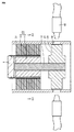
図1、図2および図3に示すように、ギャップゲージアセンブリ1は、複数のギャップゲージ2とベース3によって構成される。複数のギャップゲージ2のそれぞれは、ベース3の外周に沿って間隔を隔てて配置され、ベース3から所定の幅をもって延在するようにベース3に取り付けられている。
As shown in FIGS. 1, 2, and 3, the
複数のギャップゲージ2のそれぞれには、ベース3に取り付けるための取付穴4が形成されている。後述するように、ギャップゲージ2の所定の幅(幅b)は、電動機の固定子のティースの先端部の幅よりも長く設定されており、その先端部の幅と、隣り合うティース間の間隔(スロットの開口幅)とに基づいて、所定の範囲内の幅に設定されている。
Each of the plurality of gap gauges 2 is formed with an
次に、上述したギャップゲージアセンブリ1を用いた圧縮機の組立方法の一例について説明する。まず、図4に示すように、回転子11のシャフト12に圧縮部21とシリンダ部材22を装着する。次に、回転子11の一端側から、ギャップゲージアセンブリ1を回転子11に被せるように装着する。次に、図5に示すように、ギャップゲージアセンブリ1が装着された回転子11を、固定子13に挿入する。回転子11が固定子13に挿入された状態で、ギャップゲージアセンブリ1のギャップゲージ2が、回転子11と固定子13とのエアギャップに配置されることになる。
Next, an example of a method for assembling a compressor using the
次に、図6に示すように、溶接トーチ41を用い、容器31に形成された下穴32を介して、シリンダ部材22を容器31に溶接する。シリンダ部材22が容器31に固着された後、ギャップゲージアセンブリ1を抜き取ることで、電動機を適用した圧縮機が完成する。
Next, as shown in FIG. 6, the
完成した圧縮機では、回転子11と固定子13によって電動機部10が構成される。圧縮部21は、回転子11のシャフト12と連動している。電動機部10で発生した回転トルクは、シャフト12を介して圧縮部21に伝達される。圧縮部21には、内部に圧縮室を形成するためのローラとベーン(いずれも図示せず)が設けられたシリンダ部材22を有している。
In the completed compressor, the
上述したギャップゲージアセンブリ1を用いた圧縮機の組立方法では、ギャップゲージ2の幅bがティース16の先端部の幅よりも長く設定されており、所定の範囲内の幅に設定されていることで、回転子11の偏芯や倒れを防止することができる。このことについて、比較例との関係で説明する。
In the compressor assembling method using the
図7および図8は、比較例として、一般的な圧縮機を示す断面図である。円筒状の容器131内に、電動機部110、圧縮部121およびシリンダ部材122が配置されている。シリンダ部材122は、プラグ溶接や熱かしめ等の固着手段を用いて容器131に固定される。シリンダ部材122が容器131に固定されることで、回転子111と固定子113との相対的な位置関係が決まることになる。なお、図7〜図10では、プラグ溶接を行う場合を示し、シリンダ部材122は、容器131に設けられた下穴132において溶接トーチ141を用いてプラグ溶接によって容器131に固定される。
7 and 8 are sectional views showing a general compressor as a comparative example. An
固定子113の軸芯に対して回転子111の軸芯がずれたり、また、固定子113の軸芯に対して回転子111の軸芯が傾く(倒れ)と、磁気吸引力の平衡が崩れてしまい、これが振動や騒音の原因となる。このため、シリンダ部材122を容器131に固定する際には、固定子113と回転子111とのエアギャップを均一にするために、図8に示すように、平板状のギャップゲージ102が挿入される。
If the axis of the
図9に示すように、固定子113には、コイルを巻くためのティース116と、コイルを収容するスロット115が設けられている。ギャップゲージ102は、ティース116の位相に合わせて挿入される。図10に示すように、比較例では、矢印で示すように、ギャップゲージ102の幅方向の両端部がティース116に接触し、その両端部の間に位置する部分が回転子111に接触するように、ギャップゲージ102の幅と厚さが設定されている。
As shown in FIG. 9, the
ギャップゲージ102がティース116と回転子111に接触することで力が発生し、その力によって、エアギャップに配置された複数のギャップゲージ102のそれぞれが回転子111を押すことで、固定子113に対して回転子111が保持される。
A force is generated when the
(アンバランスになる説明)
固定子113には、隣り合うティース116の間に、スロット115に連通する開口(隙間)が位置するため、固定子113の内周面は、不連続な内周面になる。このため、図11に示すように、ティース116に対してギャップゲージ102が配置される位置がずれてしまうと、ギャップゲージ102とティース116等との接触状態が変わってしまい、ギャップゲージ102が回転子111を押す力が変化してしまう。そこで、均一な接触状態が得られるように、ギャップゲージ102の位相は、固定子113の位相に合わせられる。
(Explanation to become unbalanced)
Since the
ここで、ティースの数が比較的多い電動機では、図12に示すように、各ティース116の内側の先端部の幅は短くなり、ギャップゲージ102の幅と、ティース116の先端部の幅の差が縮まり、ギャップゲージ102の位相ずれが許容される範囲が狭められる。
Here, in an electric motor having a relatively large number of teeth, as shown in FIG. 12, the width of the front end portion of each
このため、ギャップゲージ102の加工のばらつきや、ギャップゲージ102の挿入時に捩れ等があると、複数のギャップゲージ102の中にはティース116から外れてしまうものもあり、ギャップゲージ102とティース116との接触状態にばらつきが生じることになる。
For this reason, if there are variations in processing of the
接触状態がばらつくと、ギャップゲージ102のそれぞれが、回転子111を押す力のバランスが崩れてアンバランスになる。また、固定子113の内径と、回転子111の外径の加工のばらつきによって、ギャップゲージ102の曲げ量がばらつくことによっても、ギャップゲージ102が回転子111を押す力がアンバランスになる。
If the contact state varies, each of the gap gauges 102 loses the balance of the force pushing the
ギャップゲージ102が回転子111を押す力がアンバランスになることで、図13に示すように、固定子113の軸芯に対して回転子111の軸芯が偏芯(距離A)することがある。また、図14に示すように、固定子113の軸芯に対して回転子111の軸芯が傾いてしまうことがある(角度B)。その結果、電動機部110に、振動が生じたり、騒音が発生することがある。
When the force with which the
比較例に対して、実施の形態に係る圧縮機の組立装置では、図15および図16に示すように、ギャップゲージ2の所定の幅(幅b)は、電動機の固定子のティースの先端部の幅(内周部の長さ)を幅tとし、隣り合うティース間の間隔(スロットの開口幅)を間隔dとすると、次の関係、
t+d<b<t+2d
を満たすように設定されている。なお、実際には、加工のばらつきや組立ばらつきがあるため、そのばらつきを考慮して、上記の範囲内でギャップゲージの幅bが設定される。
In contrast to the comparative example, in the compressor assembly apparatus according to the embodiment, as shown in FIGS. 15 and 16, the predetermined width (width b) of the
t + d <b <t + 2d
It is set to satisfy. Actually, since there are processing variations and assembly variations, the gap gauge width b is set within the above range in consideration of the variations.
ギャップゲージの幅bが上記関係を満たすように設定されていることで、図17に示すように、ティース16に対してギャップゲージ2がずれた(位相ずれ)としても、ギャップゲージ2の幅方向の端面が、隣りに位置するティース16の端面にガイドされることで、ギャップゲージ2がさらにずれるのを阻止することができる。
Since the gap gauge width b is set so as to satisfy the above relationship, even if the
また、このとき、ギャップゲージ2は、ティース16の幅方向の両端部に接触(矢印参照)しており、ギャップゲージ2がずれていない場合(図16)と比べて、接触状態はほとんど変わらない。このため、ギャップゲージ2に発生する力も、ギャップゲージ2がずれていない場合と比べてほとんど変わらない。
At this time, the
これにより、ギャップゲージアセンブリ1のそれぞれのギャップゲージに発生する力のバランスが図られて、回転子11の固定子13に対する偏芯や傾き(倒れ)を防止することができる。その状態で、シリンダ部材22を容器に31に固定することで、ギャップゲージアセンブリ1を取り外した後でも、偏芯や傾きが阻止される。その結果、圧縮機を動作させている際に、余計な振動や騒音が発生するのを軽減することができる。
Thereby, the balance of the force which generate | occur | produces in each gap gauge of the
変形例
上述したギャップゲージアセンブリ1では、ギャップゲージ2の長さが長くなるにしたがい、加工ばらつきによって、ギャップゲージ2の先端では、ティース16に対するずれ(位相ずれ)が大きくなることが想定される。そうなると、ティースの端面でギャップゲージをガイドすることができず、図18に示すように、ギャップゲージ2の端部が、隣に位置するティース16と回転子11との間に挟み込まれることが想定される。
Modified Example In the
このため、ギャップゲージ2の曲げ量が大きくなって、ギャップゲージ2による曲げ力が強められてしまい、ギャップゲージ2を引き抜くことができない(噛み込み)ことが想定される。
For this reason, the bending amount of the
変形例では、このような想定される不具合を阻止するギャップゲージアセンブリについて説明する。 In the modified example, a gap gauge assembly that prevents such an expected failure will be described.
図19に示すように、ギャップゲージアセンブリ1では、ベース3の外周にギャップゲージ保持部5が設けられ、ギャップゲージ2は、そのギャップゲージ保持部5に取り付けられている。図20および図21に示すように、ギャップゲージ2の取付穴4に、ギャップゲージ保持部5の軸を挿通することで、ギャップゲージ2が、取付穴4を中心にして回転可能にベース3に組み付けられている。
As shown in FIG. 19, in the
これにより、加工のばらつきによって、ギャップゲージ2のベース3に対する取付位置や取付角度がばらついてしまい、ギャップゲージアセンブリ1を装着する際に、ギャップゲージ2が隣に位置するティースに接触したとしても、ギャップゲージ2が回転して、ギャップゲージ2の端部がそのティースと回転子との間に挟み込まれるのを阻止することができる。その結果、それぞれのギャップゲージ2のティースおよび回転子に対する接触状態が均一になり、回転子を押す力のバランスが保たれて、回転子の偏芯や倒れを防止することができる。
Thereby, the mounting position and mounting angle of the
また、図22に示すように、ベース3に、ギャップゲージ2の幅よりも少し広い幅を有する溝6を設けて、ギャップゲージ2が回転する範囲を制限してもよい。これにより、ギャップゲージアセンブリ1を装着する際に、ギャップゲージ2を他の部材で押さえておく等の手間が不要になり、ギャップゲージアセンブリ1を効率的に装着することができる。
Further, as shown in FIG. 22, a
なお、ギャップゲージの断面形状として長方形を例に挙げたが、ギャップゲージと固定子または回転子との接触状態を均一にすることができれば、他の形状でもよく、たとえば、図23に示すように、円弧状の断面形状を有するギャップゲージ2を適用してもよい。
In addition, although the rectangle was mentioned as an example as a cross-sectional shape of a gap gauge, if the contact state of a gap gauge and a stator or a rotor can be made uniform, another shape may be sufficient, for example, as shown in FIG. A
実施の形態2
ここでは、電動機を適用した圧縮機の組立装置としてのギャップゲージアセンブリの他の例と、そのギャップゲージアセンブリを用いた圧縮機の組立方法について説明する。
Here, another example of a gap gauge assembly as a compressor assembly apparatus to which an electric motor is applied and a compressor assembly method using the gap gauge assembly will be described.
図24に示すように、ギャップゲージアセンブリ1は、ベース3とのそのベース3に取り付けられた複数のギャップゲージ2によって構成される。後述するように、ギャップゲージ2の幅は、前述したギャップゲージアセンブリのギャップゲージの幅よりも広く設定されており、一のティースに対し、周方向の一方の隣に位置するティースから、周方向の他方の隣に位置するティースに至る幅bに設定されている。なお、これ以外の構成については、図1、図2および図3に示すギャップゲージアセンブリと同様なので、必要である場合を除き、その説明を繰り返さないこととする。
As shown in FIG. 24, the
次に、上述したギャップゲージアセンブリ1を用いた圧縮機の組立方法の一例について説明する。
Next, an example of a method for assembling a compressor using the
まず、図25に示すように、回転子1のシャフト12に圧縮部21とシリンダ部材22を装着する。次に、回転子11の一端側から、ギャップゲージアセンブリ1を回転子11に被せるように装着する。次に、図26に示すように、ギャップゲージアセンブリ1が装着された回転子11を、固定子13に挿入する。
First, as shown in FIG. 25, the
次に、図27および図28に示すように、次に、溶接トーチ41を用い、容器31に形成された下穴32を介して、シリンダ部材22を容器31に溶接する。シリンダ部材22が容器31に固着された後、ギャップゲージアセンブリ1を抜き取ることで、電動機を適用した圧縮機が完成する。
Next, as shown in FIGS. 27 and 28, the
上述したギャップゲージアセンブリ1を用いた圧縮機の組立装置では、ギャップゲージ2の幅bは、図29に示すように、電動機の固定子のティースの先端部の幅を幅tとし、隣り合うティース間の間隔(開口幅)を間隔dとすると、次の関係、
t+2d<b<3t+2d
を満たすように設定されている。なお、実際には、加工のばらつきや組立ばらつきによって、ギャップゲージ2のティースに対する位相もばらつく。このため、そのばらつきを考慮して、上記の範囲内でギャップゲージ2の幅bが設定される。
In the compressor assembling apparatus using the
t + 2d <b <3t + 2d
It is set to satisfy. Actually, the phase of the
ギャップゲージ2の幅は、
b=2t+2d
に設定した場合に、許容しうる位相のずれが最も高くなり、t/2となる。比較例に係るギャップゲージアセンブリのギャップゲージでは、その幅(b<t)をティースの幅に近い値に設定する必要があるため、ギャップゲージの許容しうる位相のずれは0に近い値である。
The width of the
b = 2t + 2d
When set to, the allowable phase shift is the highest, which is t / 2. In the gap gauge of the gap gauge assembly according to the comparative example, the width (b <t) needs to be set to a value close to the width of the teeth, and therefore the allowable phase shift of the gap gauge is a value close to 0. .
上述したギャップゲージアセンブリ1を用いることで、許容しうる位相のずれの範囲を拡げることができる。これにより、ギャップゲージ2と回転子11および固定子13との接触状態を均一にすることができ、ギャップゲージ2に発生する曲げ量のバランスが図られて、回転子11の偏芯や倒れを防止することができる。
By using the
また、ギャップゲージ2に発生する曲げ力がばらつく原因として、固定子13の内径の寸法および回転子11の外径の寸法のばらつきによるギャップゲージ2の曲げ量のばらつきがある。上述したギャップゲージアセンブリ1では、ギャップゲージ2の曲げ量のばらつきを低減することができる。このことについて説明する。
Further, the reason why the bending force generated in the
ギャップゲージの曲げは、2点支持の梁の曲げとして考えられる。曲げ力Pは、
P=48EIw/b3
となる。ただし、Eはヤング率、Iは断面二次モーメント、wは梁のたわみ、bはギャップゲージの幅である。ギャップゲージの断面形状を長方形とした場合、
I=Lh3/12
であることから、曲げ力Pは、
P=4ELw(h/b)3
となる。ただし、hはギャップゲージの板厚、Lはギャップゲージの長さである。
The bending of the gap gauge can be considered as a bending of a beam supported at two points. The bending force P is
P = 48EIw / b 3
It becomes. Where E is the Young's modulus, I is the moment of inertia of the cross section, w is the deflection of the beam, and b is the width of the gap gauge. When the gap gauge has a rectangular cross-section,
I = Lh 3/12
Therefore, the bending force P is
P = 4 ELw (h / b) 3
It becomes. Here, h is the thickness of the gap gauge, and L is the length of the gap gauge.
ここで、ギャップゲージのたわみが、加工ばらつきによってΔw1だけ変化した場合を考える。この場合、ギャップゲージの曲げ力の変化量ΔP1は、
ΔP1=4EL(h/b)3Δw1
となる。
Here, a case is considered where the deflection of the gap gauge changes by Δw 1 due to processing variations. In this case, the change amount ΔP 1 of the bending force of the gap gauge is
ΔP 1 = 4 EL (h / b) 3 Δw 1
It becomes.
次に、ギャップゲージの幅をn倍にした幅b2(=nb1)の場合のギャップゲージの曲げ力を求める。発生する曲げ力P2は、
P2=4ELw2(h/b2)3
となる。このとき、加工ばらつきによる曲げ力の変動ΔP2は、
ΔP2=4EL(h/b2)3Δw2=4EL(h/b1)3/n3Δw2
となる。加工ばらつきを同じとすると、たわみの変動量は同じであるので、
Δw2=Δw1
となり、次の関係式、
ΔP2=4EL(b/b1)3Δw1/n3=ΔP1/n3
が導かれる。この関係式によれば、ギャップゲージの幅を拡げることで、加工ばらつきによるギャップゲージの曲げ力を減少させることができる。
Next, the bending force of the gap gauge in the case of a width b 2 (= nb 1 ) obtained by multiplying the width of the gap gauge by n times is obtained. The generated bending force P 2 is
P 2 = 4 ELw 2 (h / b 2 ) 3
It becomes. At this time, the bending force variation ΔP 2 due to processing variation is
ΔP 2 = 4EL (h / b 2 ) 3 Δw 2 = 4EL (h / b 1 ) 3 / n 3 Δw 2
It becomes. If the processing variation is the same, the amount of deflection change is the same.
Δw 2 = Δw 1
And the following relation:
ΔP 2 = 4EL (b / b 1 ) 3 Δw 1 / n 3 = ΔP 1 / n 3
Is guided. According to this relational expression, the gap gauge bending force due to processing variations can be reduced by widening the gap gauge.
以上のように、上述した実施の形態に係るギャップゲージアセンブリ1では、ギャップゲージ2の幅を上記関係を満たすように設定することで、ギャップゲージアセンブリ1を装着する際に、ギャップゲージ2の許容しうる位相のずれの範囲を拡大させることができる。
As described above, in the
また、固定子13の内径の寸法および回転子11の外径の寸法のばらつきを原因とする回転子11を押す力の変動を減少させることができ、固定子13に対する回転子11の偏芯や倒れを抑制することができる。その結果、圧縮機を動作させている際に、余計な振動や騒音が発生するのを軽減することができる。
Further, fluctuations in the force pushing the
なお、上述した各実施の形態に係るギャップゲージアセンブリ1では、ギャップゲージ2に曲げ力を発生させることによって、回転子11の偏芯や倒れを防止する場合について説明した。ギャップゲージ2としては、エアギャップ内に収まって、ギャップゲージ2に曲げ力が発生しないようなギャップゲージ2においても、上述した関係を満たすように幅を設定してもよい。この場合には、ギャップゲージ2と固定子13および回転子11との隙間がより均一になって、接触状態の均一化に寄与することができる。
In addition, in the
また、前述したギャップゲージアセンブリと同様に、ギャップゲージとしては、図23に示すように、円弧状の断面形状を有するギャップゲージ2を適用してもよい。
As in the gap gauge assembly described above, as the gap gauge, a
また、ギャップゲージアセンブリ1を用いた圧縮機の組立方法として、ギャップゲージアセンブリ1を回転子11に装着した状態で、回転子11を固定子13に挿入する場合について説明したが、ギャップゲージアセンブリ1を固定子13に装着した状態で、回転子11を固定子13に挿入するようにしてもよい。
Further, as a method of assembling the compressor using the
さらに、各実施の形態に係るギャップゲージアセンブリ1については、これを圧縮機の組立に適用する場合について説明した。ギャップゲージアセンブリとしては、圧縮機の組立に限られるものではなく、回転子のシャフトの一方が支持される電動機を備えた電動装置の組立にも適用することができる。この場合には、そのシャフトの一方に軸受けや、シャフトの回転力を受ける回転要素が取り付けられることになる。
Furthermore, about the
今回開示された実施の形態は例示であってこれに制限されるものではない。本発明は上記で説明した範囲ではなく、特許請求の範囲によって示され、特許請求の範囲と均等の意味および範囲でのすべての変更が含まれることが意図される。 The embodiment disclosed this time is an example, and the present invention is not limited to this. The present invention is defined by the terms of the claims, rather than the scope described above, and is intended to include any modifications within the scope and meaning equivalent to the terms of the claims.
本発明は、圧縮機をはじめ、回転子のシャフトの一方が支持される電動機を適用した電動装置の組立に有効に利用される。 INDUSTRIAL APPLICABILITY The present invention is effectively used for assembling electric devices using a compressor and an electric motor that supports one of the rotor shafts.
1 ギャップゲージアセンブリ、2 ギャップゲージ、3 ベース、4 取付穴、5 ギャップゲージ保持部、6 溝、10 電動機部、11 回転子、12 シャフト、13 固定子、14 エアーギャップ、15 スロット、16 ティース、21 圧縮部、22 シリンダ部材、31 容器、32 下穴、41 溶接トーチ。 1 Gap gauge assembly, 2 Gap gauge, 3 Base, 4 Mounting hole, 5 Gap gauge holding part, 6 Groove, 10 Motor part, 11 Rotor, 12 Shaft, 13 Stator, 14 Air gap, 15 Slot, 16 Teeth, 21 compression part, 22 cylinder member, 31 container, 32 pilot hole, 41 welding torch.
Claims (8)
前記回転子および前記固定子のいずれかに装着されることになるベースと、
前記ベースから幅をもって延在するように前記ベースに取り付けられ、前記回転子と前記固定子とのエアギャップに配置されることになるギャップゲージと
を含むギャップゲージアセンブリを備え、
前記ギャップゲージの前記幅を幅bとすると、
前記幅bは、前記幅tよりも長く設定されており、
前記幅bは、t+d<b<t+2dを満たすように設定された、圧縮機の組立装置。 A rotor having a shaft, and a plurality of teeth formed and inserted into the rotor, each having a width t as a width of a tip portion facing the rotor of each of the teeth; An apparatus for assembling a compressor to which an electric motor including a stator having an interval d as an interval between the tip portions is applied,
A base to be attached to either the rotor or the stator;
A gap gauge assembly including a gap gauge attached to the base so as to extend from the base and having a width and to be disposed in an air gap between the rotor and the stator ;
When the width of the gap gauge is a width b,
The width b is set longer than the width t ,
The width b is, t + d <b <is set to satisfy t + 2d, assembly apparatus compressors.
前記回転子および前記固定子のいずれかに装着されることになるベースと、
前記ベースから幅をもって延在するように前記ベースに取り付けられ、前記回転子と前記固定子とのエアギャップに配置されることになるギャップゲージと
を含むギャップゲージアセンブリを備え、
前記ギャップゲージの前記幅を幅bとすると、
前記幅bは、前記幅tよりも長く設定されており、
前記幅bは、t+2d<b<3t+2dを満たすように設定された、圧縮機の組立装置。 A rotor having a shaft, and a plurality of teeth formed and inserted into the rotor, each having a width t as a width of a tip portion facing the rotor of each of the teeth; An apparatus for assembling a compressor to which an electric motor including a stator having an interval d as an interval between the tip portions is applied,
A base to be attached to either the rotor or the stator;
A gap gauge assembly including a gap gauge attached to the base so as to extend from the base and having a width and to be disposed in an air gap between the rotor and the stator ;
When the width of the gap gauge is a width b,
The width b is set longer than the width t ,
The width b is, t + 2d <b <is set to satisfy 3t + 2d, assembly apparatus compressors.
前記回転子の前記シャフトに圧縮部を取り付ける工程と、
前記ギャップゲージアセンブリを、前記ギャップゲージが前記エアギャップに配置されることになるように、前記回転子および前記固定子のいずれかに装着する工程と、
前記回転子および前記固定子のいずれかに前記ギャップゲージアセンブリが装着された状態で、前記回転子を前記固定子に挿入する工程と、
前記固定子を収容する容器に前記圧縮部を固定する工程と
前記ギャップゲージアセンブリを取り外す工程と
を備えた、圧縮機の組立方法。 A compressor assembly method using the compressor assembly device according to any one of claims 1 to 5 ,
Attaching a compression portion to the shaft of the rotor;
Attaching the gap gauge assembly to one of the rotor and the stator such that the gap gauge is disposed in the air gap;
Inserting the rotor into the stator in a state where the gap gauge assembly is mounted on either the rotor or the stator;
An assembly method for a compressor, comprising: a step of fixing the compression portion to a container that houses the stator; and a step of removing the gap gauge assembly.
前記回転子および前記固定子のいずれかに装着されることになるベースと、
前記ベースから幅をもって延在するように前記ベースに取り付けられ、前記回転子と前記固定子とのエアギャップに配置されることになるギャップゲージと
を含むギャップゲージアセンブリを備え、
前記ギャップゲージの前記幅を幅bとすると、
前記幅bは、前記幅tよりも長く設定されており、
前記幅bは、t+d<b<t+2dを満たすように設定された、電動装置の組立装置。 A rotor having a shaft, and a plurality of teeth formed and inserted into the rotor, each having a width t as a width of a tip portion facing the rotor of each of the teeth; An assembly apparatus for an electric device comprising: an electric motor including a stator having an interval d as an interval between the tip portions; and a rotating element member including a member supporting one side of the shaft,
A base to be attached to either the rotor or the stator;
A gap gauge assembly including a gap gauge attached to the base so as to extend from the base and having a width and to be disposed in an air gap between the rotor and the stator ;
When the width of the gap gauge is a width b,
The width b is set longer than the width t ,
The electric device assembly apparatus , wherein the width b is set to satisfy t + d <b <t + 2d .
前記回転子および前記固定子のいずれかに装着されることになるベースと、
前記ベースから幅をもって延在するように前記ベースに取り付けられ、前記回転子と前記固定子とのエアギャップに配置されることになるギャップゲージと
を含むギャップゲージアセンブリを備え、
前記ギャップゲージの前記幅を幅bとすると、
前記幅bは、前記幅tよりも長く設定されており、
前記幅bは、t+2d<b<3t+2dを満たすように設定された、電動装置の組立装置。 A rotor having a shaft, and a plurality of teeth formed and inserted into the rotor, each having a width t as a width of a tip portion facing the rotor of each of the teeth; An assembly apparatus for an electric device comprising: an electric motor including a stator having an interval d as an interval between the tip portions; and a rotating element member including a member supporting one side of the shaft,
A base to be attached to either the rotor or the stator;
A gap gauge assembly including a gap gauge attached to the base so as to extend from the base and having a width and to be disposed in an air gap between the rotor and the stator ;
When the width of the gap gauge is a width b,
The width b is set longer than the width t ,
The electric device assembly apparatus , wherein the width b is set to satisfy t + 2d <b <3t + 2d .
Priority Applications (1)
| Application Number | Priority Date | Filing Date | Title |
|---|---|---|---|
| JP2013261140A JP6095560B2 (en) | 2013-12-18 | 2013-12-18 | Compressor assembly apparatus, compressor assembly method, and electric apparatus assembly apparatus |
Applications Claiming Priority (1)
| Application Number | Priority Date | Filing Date | Title |
|---|---|---|---|
| JP2013261140A JP6095560B2 (en) | 2013-12-18 | 2013-12-18 | Compressor assembly apparatus, compressor assembly method, and electric apparatus assembly apparatus |
Publications (2)
| Publication Number | Publication Date |
|---|---|
| JP2015119548A JP2015119548A (en) | 2015-06-25 |
| JP6095560B2 true JP6095560B2 (en) | 2017-03-15 |
Family
ID=53531829
Family Applications (1)
| Application Number | Title | Priority Date | Filing Date |
|---|---|---|---|
| JP2013261140A Active JP6095560B2 (en) | 2013-12-18 | 2013-12-18 | Compressor assembly apparatus, compressor assembly method, and electric apparatus assembly apparatus |
Country Status (1)
| Country | Link |
|---|---|
| JP (1) | JP6095560B2 (en) |
Families Citing this family (1)
| Publication number | Priority date | Publication date | Assignee | Title |
|---|---|---|---|---|
| CN110932508B (en) * | 2019-12-30 | 2021-07-02 | 安徽大学 | Positioning false ball structure and spherical motor rotor aligning positioning method |
Family Cites Families (8)
| Publication number | Priority date | Publication date | Assignee | Title |
|---|---|---|---|---|
| US3320660A (en) * | 1962-12-11 | 1967-05-23 | Gen Electric | Methods for assembling end shield members in dynamoelectric machines |
| JP3561619B2 (en) * | 1997-12-15 | 2004-09-02 | 三洋電機株式会社 | Motor assembly method and device |
| DE19845683A1 (en) * | 1998-10-05 | 2000-04-06 | Mannesmann Vdo Ag | Method of assembling an electric motor |
| AT414289B (en) * | 2002-09-30 | 2006-11-15 | M & R Automation Gmbh | METHOD AND DEVICE FOR AUTOMATED MOUNTING OF ELECTRIC MOTORS |
| JP2005151716A (en) * | 2003-11-17 | 2005-06-09 | Matsushita Electric Ind Co Ltd | Motor and its manufacturing method, and motor-driven compressor |
| JP5375534B2 (en) * | 2009-11-11 | 2013-12-25 | ダイキン工業株式会社 | Compressor and manufacturing method thereof |
| JP2012120326A (en) * | 2010-11-30 | 2012-06-21 | Fujitsu General Ltd | Interior magnet rotor, motor, and method for assembling motor |
| JP6074887B2 (en) * | 2011-11-30 | 2017-02-08 | 株式会社富士通ゼネラル | Gap gauge used for assembling electric motor and method for manufacturing electric motor |
-
2013
- 2013-12-18 JP JP2013261140A patent/JP6095560B2/en active Active
Also Published As
| Publication number | Publication date |
|---|---|
| JP2015119548A (en) | 2015-06-25 |
Similar Documents
| Publication | Publication Date | Title |
|---|---|---|
| KR101531920B1 (en) | Radial foil bearing | |
| JP3463026B2 (en) | Dynamic pressure type air bearing | |
| JP2012082792A (en) | Electric compressor | |
| JP6282340B2 (en) | Wave generator for wave gear device and method for manufacturing wave generator | |
| JP2010063351A (en) | Stator, motor and compressor | |
| JP6189001B1 (en) | Induction motor rotor and induction motor | |
| JP6095560B2 (en) | Compressor assembly apparatus, compressor assembly method, and electric apparatus assembly apparatus | |
| JP2011200050A (en) | Stator, motor and compressor | |
| JP2009050098A (en) | Stator, manufacturing method therefor and compressor | |
| JP2011236898A (en) | Blade having asymmetrical mid-span structure portions and related bladed wheel structure | |
| WO2015064300A1 (en) | Compressor and method for producing compressor | |
| JP2020096396A (en) | Rotor and motor with the same | |
| JP5098570B2 (en) | Rotating electrical machine manufacturing method and rotating electrical machine | |
| JP6967987B2 (en) | Rotor, motor and rotor manufacturing method | |
| JP4935435B2 (en) | Shrink fit fastening structure of gas turbine | |
| JP5975948B2 (en) | Rotating electric machine laminated iron core, rotating electric machine stator and rotating electric machine laminated iron core manufacturing method | |
| JP5449976B2 (en) | Shaft seal device, turbine device, and shaft seal device gap adjusting method | |
| US9634545B2 (en) | Component for an electric machine | |
| JP2004293446A (en) | Hermetic compressor | |
| JP2017204965A (en) | Armature, method of manufacturing the same, and rotary electric machine | |
| JP5818840B2 (en) | Compressor assembly apparatus and assembly method | |
| JP2008278597A (en) | Rotor core | |
| JP4888461B2 (en) | Compressor | |
| JP5874418B2 (en) | Motor and compressor | |
| JP5690305B2 (en) | Spring assembly |
Legal Events
| Date | Code | Title | Description |
|---|---|---|---|
| A621 | Written request for application examination |
Free format text: JAPANESE INTERMEDIATE CODE: A621 Effective date: 20150917 |
|
| A977 | Report on retrieval |
Free format text: JAPANESE INTERMEDIATE CODE: A971007 Effective date: 20160615 |
|
| A131 | Notification of reasons for refusal |
Free format text: JAPANESE INTERMEDIATE CODE: A131 Effective date: 20160621 |
|
| A521 | Written amendment |
Free format text: JAPANESE INTERMEDIATE CODE: A523 Effective date: 20160802 |
|
| TRDD | Decision of grant or rejection written | ||
| A01 | Written decision to grant a patent or to grant a registration (utility model) |
Free format text: JAPANESE INTERMEDIATE CODE: A01 Effective date: 20170117 |
|
| A61 | First payment of annual fees (during grant procedure) |
Free format text: JAPANESE INTERMEDIATE CODE: A61 Effective date: 20170214 |
|
| R150 | Certificate of patent or registration of utility model |
Ref document number: 6095560 Country of ref document: JP Free format text: JAPANESE INTERMEDIATE CODE: R150 |
|
| R250 | Receipt of annual fees |
Free format text: JAPANESE INTERMEDIATE CODE: R250 |
|
| R250 | Receipt of annual fees |
Free format text: JAPANESE INTERMEDIATE CODE: R250 |
|
| R250 | Receipt of annual fees |
Free format text: JAPANESE INTERMEDIATE CODE: R250 |
|
| R250 | Receipt of annual fees |
Free format text: JAPANESE INTERMEDIATE CODE: R250 |