JP6095117B2 - Beam monitor system and particle beam irradiation system - Google Patents
Beam monitor system and particle beam irradiation system Download PDFInfo
- Publication number
- JP6095117B2 JP6095117B2 JP2013164438A JP2013164438A JP6095117B2 JP 6095117 B2 JP6095117 B2 JP 6095117B2 JP 2013164438 A JP2013164438 A JP 2013164438A JP 2013164438 A JP2013164438 A JP 2013164438A JP 6095117 B2 JP6095117 B2 JP 6095117B2
- Authority
- JP
- Japan
- Prior art keywords
- irradiation
- monitor
- group
- signal processing
- charged particle
- Prior art date
- Legal status (The legal status is an assumption and is not a legal conclusion. Google has not performed a legal analysis and makes no representation as to the accuracy of the status listed.)
- Active
Links
Images


Classifications
-
- G—PHYSICS
- G01—MEASURING; TESTING
- G01T—MEASUREMENT OF NUCLEAR OR X-RADIATION
- G01T1/00—Measuring X-radiation, gamma radiation, corpuscular radiation, or cosmic radiation
- G01T1/29—Measurement performed on radiation beams, e.g. position or section of the beam; Measurement of spatial distribution of radiation
- G01T1/2914—Measurement of spatial distribution of radiation
- G01T1/2921—Static instruments for imaging the distribution of radioactivity in one or two dimensions; Radio-isotope cameras
- G01T1/2935—Static instruments for imaging the distribution of radioactivity in one or two dimensions; Radio-isotope cameras using ionisation detectors
-
- A—HUMAN NECESSITIES
- A61—MEDICAL OR VETERINARY SCIENCE; HYGIENE
- A61N—ELECTROTHERAPY; MAGNETOTHERAPY; RADIATION THERAPY; ULTRASOUND THERAPY
- A61N5/00—Radiation therapy
- A61N5/10—X-ray therapy; Gamma-ray therapy; Particle-irradiation therapy
- A61N5/1048—Monitoring, verifying, controlling systems and methods
- A61N5/1064—Monitoring, verifying, controlling systems and methods for adjusting radiation treatment in response to monitoring
- A61N5/1065—Beam adjustment
-
- A—HUMAN NECESSITIES
- A61—MEDICAL OR VETERINARY SCIENCE; HYGIENE
- A61N—ELECTROTHERAPY; MAGNETOTHERAPY; RADIATION THERAPY; ULTRASOUND THERAPY
- A61N5/00—Radiation therapy
- A61N5/10—X-ray therapy; Gamma-ray therapy; Particle-irradiation therapy
- A61N5/1077—Beam delivery systems
-
- A—HUMAN NECESSITIES
- A61—MEDICAL OR VETERINARY SCIENCE; HYGIENE
- A61N—ELECTROTHERAPY; MAGNETOTHERAPY; RADIATION THERAPY; ULTRASOUND THERAPY
- A61N5/00—Radiation therapy
- A61N5/10—X-ray therapy; Gamma-ray therapy; Particle-irradiation therapy
- A61N5/1048—Monitoring, verifying, controlling systems and methods
- A61N2005/1074—Details of the control system, e.g. user interfaces
Description
本発明は荷電粒子ビーム(粒子線)の照射システムにおけるビーム位置を監視するビームモニタシステムに係り、特に、陽子や炭素イオン等の粒子線を患部に照射して治療する粒子線治療装置に適用するのに好適な粒子線照射システムのビームモニタシステムに関する。 The present invention relates to a beam monitor system that monitors a beam position in a charged particle beam (particle beam) irradiation system, and more particularly, to a particle beam therapy apparatus that irradiates an affected area with a particle beam such as protons or carbon ions. The present invention relates to a beam monitor system of a particle beam irradiation system suitable for the above.
がん等の患者の患部に陽子もしくは炭素イオン等の荷電粒子ビーム(粒子線、イオンビーム)を照射する治療方法が知られている。この治療に用いる粒子線照射システムは、荷電粒子ビーム発生装置を備えている。荷電粒子ビーム発生装置で加速されたイオンビームは、第1ビーム輸送系および回転ガントリに設けられた第2ビーム輸送系を経て回転ガントリに設置された照射装置に達する。イオンビームは照射装置より出射されて患者の患部に照射される。 There is known a treatment method in which an affected part of a patient such as cancer is irradiated with a charged particle beam (particle beam, ion beam) such as proton or carbon ion. The particle beam irradiation system used for this treatment includes a charged particle beam generator. The ion beam accelerated by the charged particle beam generator reaches the irradiation device installed in the rotating gantry via the first beam transporting system and the second beam transporting system provided in the rotating gantry. The ion beam is emitted from the irradiation device and irradiated to the affected area of the patient.
照射装置の照射方式としては、例えば非特許文献1に記載のような、散乱体によってビームを広げた後に患部形状に合せて切り出す二重散乱体方式(非特許文献1の2081頁、図35)、ウォブラ法(非特許文献1の2084頁、図41)、および細かいビームを患部領域内に走査させるスキャニング方式(非特許文献1の2092頁および2093頁)が知られている。
As an irradiation method of the irradiation device, for example, as described in
上記のビーム照射法の中でも、正常細胞に対する影響が少なく、ノズル内蔵機器が不要であるという特徴からスキャニング方式に注目が集まっている。スキャニング方式は、照射対象への照射量に対応して荷電粒子ビームの出力を停止させ、エネルギーおよび走査電磁石を制御することによりスポットと呼ばれる荷電粒子ビームの照射位置を変更し、変更完了後に荷電粒子ビームの出射を再開することで、順次照射位置を切り替えながら照射対象(患部)の形状に合わせてビームを照射することが特徴である。 Among the beam irradiation methods described above, the scanning method has attracted attention because it has little influence on normal cells and does not require a device with a built-in nozzle. The scanning method stops the output of the charged particle beam according to the irradiation amount to the irradiation target, changes the irradiation position of the charged particle beam called a spot by controlling the energy and the scanning magnet, and after the change is completed, the charged particle It is characterized by irradiating the beam in accordance with the shape of the irradiation target (affected part) while switching the irradiation position sequentially by restarting the beam emission.
荷電粒子照射システムにおいては、患部の形状に合わせて照射するために走査電磁石下流側、照射対象である患者の直前にビーム位置監視モニタ(以降、スポット位置モニタと呼ぶ)が設置される。 In the charged particle irradiation system, a beam position monitor (hereinafter referred to as a spot position monitor) is installed on the downstream side of the scanning electromagnet and immediately before the patient to be irradiated in order to perform irradiation in accordance with the shape of the affected area.
スポット位置モニタはマルチワイヤと呼ばれる検出器(以降、チャンネルと呼ぶ)からなり、チャンネル毎にビームの通過によって発生した電荷量をコンデンサに蓄積し、誘起された電圧を読み出す方式の検出器である。各チャンネルで検出する信号は微弱であることからチャンネルの下流側には増幅器が設置され、チャンネルで検出した信号(検出信号)は増幅器を介して信号処理装置に送られる。信号処理装置が全てのマルチワイヤからの検出信号を受け取ることによって、ビームの位置および幅を検出することができる。 The spot position monitor is composed of a detector (hereinafter referred to as a channel) called a multi-wire, and is a detector of a type in which the amount of charge generated by the passage of the beam is accumulated in a capacitor for each channel and the induced voltage is read out. Since the signal detected in each channel is weak, an amplifier is installed on the downstream side of the channel, and the signal (detection signal) detected in the channel is sent to the signal processing device via the amplifier. By receiving detection signals from all the multi-wires, the signal processing device can detect the position and width of the beam.
スポット位置モニタのビーム位置及びビーム幅の検出精度を向上するために、チャンネル数を増やすことが考えられる。スポット位置モニタには、チャンネル数に伴い信号増幅器や信号処理装置が必要であり、ビームの位置および幅検出には全てのチャンネルに対して信号増幅および信号処理を行う為、チャンネル数が増えるほどモニタシステムが大規模かつ複雑な構成になり、またコストが高くなってしまう課題があった。 In order to improve the detection accuracy of the beam position and beam width of the spot position monitor, it is conceivable to increase the number of channels. Spot position monitoring requires a signal amplifier and signal processing device according to the number of channels, and because beam amplification and signal processing are performed for all channels for beam position and width detection, monitoring increases as the number of channels increases. There is a problem that the system becomes a large-scale and complicated configuration, and the cost becomes high.
本発明の目的は、スキャニング方式のスポット照射において、正確な位置特定を行うことができ、適切な照射であるか否かという判断を高精度化することができるビームモニタシステムおよびそれを備えた粒子線照射システムを提供することを目的とする。 An object of the present invention is to provide a beam monitor system capable of accurately specifying a position in scanning-type spot irradiation and capable of determining whether or not the irradiation is appropriate, and particles including the beam monitor system. An object is to provide a beam irradiation system.
上記課題を解決するために、例えば特許請求の範囲に記載の構成を採用する。
本発明は、上記課題を解決する手段を複数含んでいるが、その一例を挙げるならば、収集電極と、信号処理装置と、ビームモニタ制御装置とを備えたビームモニタシステムであって、前記収集電極は、通過する荷電粒子ビームを検出する電極であって、隣り合う複数のワイヤ電極を一つのグループとした前記グループを複数有し、このグループは隣り合う複数の前記ワイヤ電極で構成される区分に分割され、あるグループのある区分に属する各々の前記ワイヤ電極は他のグループに属する区分のいずれか一つの前記ワイヤ電極とそれぞれ同一の配線によって前記信号処理装置に対して各々接続され、このうち他のグループに属する区分のいずれか一つの前記ワイヤ電極は2チャンネルは物理的に連続しないようにグループ毎に異なるように置換されて前記同一の配線によって前記信号処理装置に対して各々接続されており、前記信号処理装置は、前記ワイヤ電極から出力された検出信号を計画したビーム照射目標位置に関連する情報と前記置換接続の情報とに基づいて並び替え、処理信号として出力し、前記ビームモニタ制御装置は、前記信号処理装置から出力された処理信号に基づいて、前記ワイヤ電極を通過した荷電粒子ビームのビーム位置とビーム幅とを演算することを特徴とする。
In order to solve the above problems, for example, the configuration described in the claims is adopted.
The present invention includes a plurality of means for solving the above-described problems. For example, a beam monitor system including a collection electrode, a signal processing device, and a beam monitor control device, the collection electrodes is a detector to electrodes of the charged particle beam passing through, it has a plurality of the groups in which the plurality of wire electrode adjacent to one group, made up of a plurality of the wire electrode this group adjacent Each of the wire electrodes belonging to a certain section of a certain group is connected to the signal processing device by the same wiring as any one of the above-described wire electrodes belonging to another group, out of any one of the sections belonging to another group the
本発明によれば、正確な位置へのビーム照射だけでなく、誤った位置へのビーム照射を正確に検出することができるビームモニタシステムを実現することができ、スキャニング方式のスポット照射において、正確な位置特定を行うことができ、適切な照射であるか否かの判断を高精度化することができる。 According to the present invention, it is possible to realize a beam monitor system capable of accurately detecting not only beam irradiation at an accurate position but also beam irradiation at an incorrect position. Therefore, it is possible to specify the position accurately and to determine whether or not the irradiation is appropriate.
以下に本発明のビームモニタシステムおよび粒子線照射システムの実施形態を、図面を用いて説明する。 Hereinafter, embodiments of a beam monitor system and a particle beam irradiation system of the present invention will be described with reference to the drawings.
<第1の実施形態>
本発明のビームモニタシステムおよび粒子線照射システムの第1の実施形態を、図1乃至図14を用いて説明する。
なお、本発明において、粒子線照射システムとは、治療室内の治療台(ベッド装置)10上に固定された患者の患部に対して荷電粒子ビーム12(例えば、陽子線や炭素線等)を照射するシステムのことを意味する。
<First Embodiment>
A first embodiment of a beam monitor system and a particle beam irradiation system according to the present invention will be described with reference to FIGS.
In the present invention, the particle beam irradiation system refers to irradiation of a charged particle beam 12 (for example, proton beam or carbon beam) onto an affected part of a patient fixed on a treatment table (bed apparatus) 10 in a treatment room. It means the system to do.
まず、本発明の粒子線照射システムの構成について、図1乃至図4を用いて説明する。
図1は本発明の粒子線照射システムの第1の実施形態の全体構成を示す構成図、図2は本発明の粒子線照射システムの第1の実施形態を構成するスキャニング照射システムおよび照射制御システムの概略を示す構成図、図3は本発明の粒子線照射システムの第1の実施形態におけるビームモニタシステムの概略図、図4はスキャニング照射方式による荷電粒子ビーム照射の制御のフローチャート図である。
First, the structure of the particle beam irradiation system of this invention is demonstrated using FIG. 1 thru | or FIG.
FIG. 1 is a configuration diagram showing the overall configuration of a first embodiment of the particle beam irradiation system of the present invention, and FIG. 2 is a scanning irradiation system and an irradiation control system that configure the first embodiment of the particle beam irradiation system of the present invention. FIG. 3 is a schematic diagram of a beam monitor system in the first embodiment of the particle beam irradiation system of the present invention, and FIG. 4 is a flowchart of control of charged particle beam irradiation by a scanning irradiation method.
本実施形態の粒子線照射システムは、荷電粒子ビーム発生装置1、ビーム輸送系2、スキャニング照射装置3および制御システム4を概略備えている。
The particle beam irradiation system of the present embodiment generally includes a charged particle
荷電粒子ビーム発生装置1は、イオン源(図示せず)、前段加速器15および円形加速器(シンクロトロン)16を有する。本実施形態では、円形加速器16としてシンクロトロンを例に説明するが、サイクロトロン等の他の加速器であってもよい。前段加速器15の上流側にイオン源が接続され、前段加速器15の下流側に円形加速器16が接続される。
The charged
ビーム輸送系2は、荷電粒子ビーム発生装置1の下流側に接続されており、荷電粒子ビーム発生装置1とスキャニング照射装置3とを接続する。
The
スキャニング照射装置3は、荷電粒子ビーム12を患者の患部に照射するための装置であり、図2に示すように、患者13を載せる治療台10、照射ノズル(ノズル装置)11および回転ガントリ14とを概略備える。
治療台10は、治療室内に配置されており、患者13を載せて、患部の位置決めを行う。
照射ノズル11には、図2に示すように、荷電粒子ビーム12の進行方向の上流側から順番に、上流ビームモニタ11a、走査電磁石11b、線量モニタ11cおよび下流ビームモニタ11dがビーム経路に沿って配置される。照射ノズル11は、スキャニングビームの照射野を形成する。
上流ビームモニタ11aは、照射ノズル11内に入射された荷電粒子ビーム12の通過位置およびビーム幅(ビーム径)を計測する。
走査電磁石11bは、通過する荷電粒子ビームを第一の方向(例えば、X軸方向)に偏向・走査する第1走査電磁石11b1と、第一の方向と垂直な第二の方向(例えば、Y軸方向)に荷電粒子ビームを偏向・走査する第二走査電磁石11b2を備える。ここで、X軸方向とは、照射ノズル11に入射された荷電粒子ビームの進行方向に垂直な平面内の一方向であり、Y軸方向とは、当該平面内であってX軸と垂直な方向を示す。
線量モニタ11cは、通過する荷電粒子ビームの照射線量を計測する。すなわち、線量モニタ11cは、患者に照射された荷電粒子ビームの照射線量を監視するモニタである。
下流ビームモニタ11dは、走査電磁石11bの下流側に設置され、通過する荷電粒子ビームの位置およびビーム幅を計測する。すなわち、下流ビームモニタ11dは、走査電磁石11bによって走査された荷電粒子ビームの位置およびビーム幅を計測するモニタである。
The
The treatment table 10 is disposed in the treatment room, and places the
The
The upstream beam monitor 11 a measures the passing position and the beam width (beam diameter) of the
The scanning electromagnet 11b includes a first scanning electromagnet 11b1 that deflects and scans a passing charged particle beam in a first direction (for example, the X-axis direction), and a second direction (for example, the Y-axis) that is perpendicular to the first direction. A second scanning electromagnet 11b2 that deflects and scans the charged particle beam in the direction). Here, the X-axis direction is one direction in a plane perpendicular to the traveling direction of the charged particle beam incident on the
The
The
回転ガントリ14は、アイソセンタ(図示せず)を中心に回転可能な構成であり、ビームの照射角度を決める。回転ガントリ14が回転することによって、患者13に照射する荷電粒子ビーム12の照射角度を変更することができる。
The rotating
制御システム4は、図1に示すように、中央制御装置5、加速器・輸送系制御システム7および照射制御システム8を概略備える。
中央制御装置5は、治療計画装置6、加速器・輸送系制御システム7、照射制御システム8および操作端末40に接続される。この中央制御装置5は、治療計画装置6からの設定データに基づいて、加速器運転のための運転パラメータの設定値、照射野を形成するための運転パラメータ、計画されるビーム位置およびビーム幅、線量の設定値を算出する機能を備えている。これらの運転パラメータおよびモニタ設定値は、中央制御装置5から加速器・輸送系制御システム7および照射制御システム8に出力される。
加速器・輸送系制御システム7は、荷電粒子ビーム発生装置1およびビーム輸送系2に接続され、荷電粒子ビーム発生装置1およびビーム輸送系2を構成する機器を制御する。
照射制御システム8は、スキャニング照射装置3に接続され、スキャニング照射装置3を構成する機器を制御する。
操作端末40は、操作者(医者、オペレータ等の医療従事者)がデータや指示信号を入力する入力装置および表示画面を備えている。
As shown in FIG. 1, the
The
The accelerator / transport system control system 7 is connected to the charged
The irradiation control system 8 is connected to the
The
照射制御システム8について、図2を用いて説明する。
照射制御システム8は、患者機器制御装置8a、モニタ監視制御装置8bおよび走査電磁石電源制御装置8cを備える。
患者機器制御装置8aは、回転ガントリ14を構成する各機器を制御する回転ガントリ制御装置8a1、治療台10を移動して位置決め制御する治療台制御装置8a2、ノズル11内に配置された機器を制御するノズル内機器制御装置8a3を備えている。このうち、回転ガントリ制御装置8a1は、回転ガントリ14の回転角度を制御することで、患者13に照射する荷電粒子ビームの照射角度を制御する。
The irradiation control system 8 will be described with reference to FIG.
The irradiation control system 8 includes a patient
The patient
モニタ監視制御装置8bは、上流ビームモニタ11aを監視制御する上流ビームモニタ監視制御装置8b1、下流ビームモニタ11dを監視制御する下流ビームモニタ監視制御装置8b2、線量モニタ11cを監視制御する線量監視制御装置8b3を概略備える。
The monitor
上流ビームモニタ監視制御装置8b1は上流ビームモニタ11aに入射された荷電粒子ビームのビーム位置およびビーム幅を計測する機能を有し、荷電粒子ビームに異常がないか否かを判定する機能(異常判定処理)を有する。
下流ビームモニタ監視制御装置8b2は、走査電磁石11bによって走査され、下流ビームモニタ11dに入射された荷電粒子ビームのビーム位置およびビーム幅を計測する機能を有する。すなわち、走査された荷電粒子ビームのビーム位置およびビーム幅に異常がないか否かを判定する機能(異常判定処理)を有する。上流ビームモニタ監視制御装置8b1や下流ビームモニタ監視制御装置8b2の機構は、具体的には以下の通りである。
The upstream beam monitor monitoring controller 8b1 has a function of measuring the beam position and beam width of the charged particle beam incident on the
The downstream beam monitor monitoring control device 8b2 has a function of measuring the beam position and beam width of the charged particle beam scanned by the scanning electromagnet 11b and incident on the
上流ビームモニタ監視制御装置8b1は、上流ビームモニタ11aで計測された計測データを受信して演算処理し、荷電粒子ビームが通過した位置およびビーム幅を求める。求めたビーム位置が予め定められた範囲外の場合、またはビーム幅が予め定められた範囲外の場合、上流ビームモニタ監視制御装置8b1は、ビーム異常と判定し、中央制御装置5に異常信号を出力する。
The upstream beam monitor monitoring control device 8b1 receives the measurement data measured by the
下流ビームモニタ監視制御装置8b2は、下流ビームモニタ11dで計測した計測データを受信して演算処理し、荷電粒子ビームが通過した位置およびビーム幅を求める。求めたビーム位置が予め定められた範囲外の場合、またはビーム幅が予め定められた範囲外の場合、下流ビームモニタ監視制御装置8b2はビーム異常と判定し、中央制御装置5に異常信号を出力する。
中央制御装置5は、上流ビームモニタ監視制御装置8b1または下流ビームモニタ監視制御装置8b2から異常信号を入力すると、加速器・輸送系制御システム7にビーム停止指令信号を出力し、荷電粒子ビーム発生装置1から出射する荷電粒子ビームを停止させる。
本実施形態では、荷電粒子ビーム発生装置1から出射する荷電粒子ビームを停止するように制御したが、中央制御装置5がビーム輸送系2を制御し、照射ノズル11に入射される荷電粒子ビームを停止するように制御してもよい。
ここで、荷電粒子ビームのビーム位置とは、例えば、ビームモニタ(上流ビームモニタ11aまたは下流ビームモニタ11d)を通過する荷電粒子ビームの重心位置のことを示す。
また、荷電粒子ビームのビーム幅とは、ビームモニタ(上流ビームモニタ11aまたは下流ビームモニタ11d)を通過した荷電粒子ビームの領域を示す。ビーム幅の求め方には、例えば、ビーム進行方向に垂直な平面上に配置されたビームモニタ(上流ビームモニタ11aまたは下流ビームモニタ11d)で荷電粒子ビームを検出した領域の面積を算出する方法や、このようなビームモニタでの荷電粒子ビームの検出領域の面積および当該検出領域の幅を算出する方法などがある。
Downstream beam monitor monitoring controller 8b2 receives the measurement data measured by the downstream beam monitor 11 d and arithmetic processing to obtain the position and the beam width charged particle beam has passed. If the obtained beam position is out of the predetermined range or the beam width is out of the predetermined range, the downstream beam monitor monitoring control device 8b2 determines that the beam is abnormal and outputs an abnormal signal to the
When the
In the present embodiment, the charged particle beam emitted from the charged
Here, the beam position of the charged particle beam indicates, for example, the barycentric position of the charged particle beam passing through the beam monitor (
The beam width of the charged particle beam indicates a region of the charged particle beam that has passed through the beam monitor (
走査電磁石電源制御装置8cは、走査電磁石11bの電源装置(図示せず)を制御することによって、走査電磁石11bに励磁する励磁電流を制御し、患者13への荷電粒子ビームの照射位置を変更する。
Scanning magnet power supply control unit 8c, by controlling the power supply of the scanning electromagnet 11b (not shown) to control the exciting current for exciting the scan electromagnets 11b, and the irradiation position of the charged particle beam to the
次に、図4を用いて、患者に対する治療開始から治療終了までの流れを説明する。
本実施形態では、患者13の患部をビーム進行方向(患者13の体表面からの深さ方向)に対して複数の層(以下、レイヤーという)に分割し、各レイヤーを複数のスポットである小領域に分けてビーム照射するスポットスキャニング照射法を例に説明する。
Next, a flow from the start of treatment to the end of treatment will be described with reference to FIG.
In this embodiment, the affected part of the
治療計画装置6は、予め取得された患者の治療計画情報を記憶している。治療計画情報は、照射データ(ビームエネルギー情報、照射位置情報、各照射位置に対する荷電粒子ビームの目標線量値等)および許容値データ(上流ビームモニタ11aでの許容ビーム位置情報および許容ビーム幅情報や、各照射位置に対する下流ビームモニタ11dでの許容ビーム位置情報および許容ビーム幅情報等)を含んでいる。
なお、本実施形態では、治療計画装置6が照射データおよび許容値データを求める構成としたが、治療計画装置6が照射データを求め、中央制御装置5が許容値データを求める構成としても良い。この場合、治療計画装置6は、許容値データを求めるのに必要なデータを中央制御装置5に送信し、中央制御装置5は受け取ったデータに基づいて許容値データを算出する。照射データである目標線量値は、各レイヤー内のスポット位置毎に定められる。
The treatment planning device 6 stores treatment plan information of a patient acquired in advance. The treatment plan information includes irradiation data (beam energy information, irradiation position information, target dose value of charged particle beam for each irradiation position, etc.) and allowable value data (allowable beam position information and allowable beam width information in the
In the present embodiment, the treatment planning device 6 obtains irradiation data and allowable value data. However, the treatment planning device 6 may obtain irradiation data and the
患者13が治療台(ベッド)上に固定されると、医師は操作端末40の入力装置から準備開始信号を入力する。
準備開始信号を受信した中央制御装置5は、該当する患者の治療計画情報を治療計画装置6から受け取り、治療台制御装置8a2にベッド位置情報を出力する。治療台制御装置8a2は、ベッド位置情報に基づいて患者13をビーム軸の延長線上の所定位置に配置するように治療台10を移動し、位置決めする。また、中央制御装置5は、回転ガントリ制御装置8a1にガントリ角度情報を出力する。回転ガントリ制御装置8a1は、ガントリ角度情報に基づいて回転ガントリ14を回転させて所定の角度に配置する。また、中央制御装置5は、照射位置毎の荷電粒子ビームの目標線量値や許容値データをモニタ監視制御装置8bに送信する。中央制御装置5は、照射データに含まれるビームエネルギー情報および照射位置情報に基づいて、走査電磁石11bに励磁すべき励磁電流値を算出し、励磁電流パラメータを求め、走査電磁石電源制御装置8cに励磁電流パラメータを送信する。さらに、中央制御装置5は、治療計画情報に基づいて円形加速器16の加速運転のための運転パラメータや、円形加速器16から出射された荷電粒子ビームを照射ノズル11に輸送するためのビーム輸送系2の運転パラメータを求め、加速器・輸送系制御システム7にこれらの運転パラメータを送信する。
When the
The
治療の準備が完了すると、医師は操作端末40の入力装置から治療開始信号を入力する。
治療開始信号が入力された中央制御装置5は、加速器・輸送系制御システム7に指令信号を送信する。
次いで、加速器・輸送系制御システム7は、最初に照射するレイヤー(最初のビームエネルギー情報)に相当する運転パラメータを円形加速器16およびビーム輸送系2に設定する。円形加速器16およびビーム輸送系2の運転パラメータが設定されて運転開始準備が完了すると(ステップS30)、走査電磁石電源制御装置8cは励磁電流パラメータに基づいて走査電磁石11bを励磁する(ステップS31)。最初の照射スポットに対応する励磁電流が走査電磁石11bに励磁された後、モニタ監視制御装置8bの線量監視制御装置8b3が、当該スポット位置に対する目標線量値に基づいてビームの照射線量の監視を開始し(ステップS32)、照射準備が完了する。
When preparation for treatment is completed, the doctor inputs a treatment start signal from the input device of the
The
Next, the accelerator / transport system control system 7 sets operation parameters corresponding to the layer to be irradiated first (first beam energy information) in the
中央制御装置5がビーム出射開始指令を送信すると(ステップS33)、加速器・輸送系制御システム7はイオン源を起動し、荷電粒子(陽子または重粒子)を生成する。前段加速器15は、イオン源からの荷電粒子を加速し、円形加速器16に出射する。円形加速器16は、荷電粒子ビームを更に加速する。周回する荷電粒子ビームは目標エネルギーまで加速され、円形加速器16からビーム輸送系2に出射される。荷電粒子ビームは、ビーム輸送系2を経てスキャニング照射装置3に到達する。荷電粒子ビームは、照射ノズル11内をビーム軸に沿って進行し、上流ビームモニタ11a,走査電磁石11b,線量モニタ11cおよび下流ビームモニタ11dを通過する。照射ノズル11から出射された荷電粒子ビームが患者13の患部に照射される。
When the
線量監視制御装置8b3は、線量モニタ11cで計測した計測データを受け取って演算処理し、当該照射スポットに対する照射線量を求める。最初の照射スポットに対する照射線量値が目標線量値に達するまで荷電粒子ビームの照射を続ける。線量監視制御装置8b3は、照射線量値が目標線量値に達したと判断すると、中央制御装置5に対して照射満了信号を出力する(ステップS34)。中央制御装置5は、照射満了信号を受けて荷電粒子ビームの出射を停止する(ステップS35)。
The dose monitoring control device 8b3 receives the measurement data measured by the
次いで、上流ビームモニタ11aで検出した第1検出データを上流ビームモニタ監視制御装置8b1で取り込むとともに、下流ビームモニタ11dで検出した第2検出データを下流ビームモニタ監視制御装置8b2で取り込む。そして、照射された荷電粒子ビームの位置およびビーム幅を求める(ステップS36)。
演算処理が終了し、ビームの位置およびビーム幅に異常がなければ(ビーム位置が許容ビーム位置の範囲内であり、ビーム幅が許容ビーム幅の範囲内と判断されれば)、照射満了した照射スポットがレイヤー内での最後のスポット位置であるか否かを判定する。最後の照射スポット位置でないと判断された場合(Noの場合)はステップS31に戻り、走査電磁石電源制御装置8cは、次のスポットに荷電粒子ビームを照射するように走査電磁石11bの励磁電流値を変更する。
走査電磁石電源制御装置8cは励磁電流パラメータに基づいて走査電磁石11bを励磁すると(ステップS31)、モニタ監視制御装置8bの線量監視制御装置8b3は、次の照射スポット位置に対する目標線量値に基づいてビーム線量の監視を再開する(ステップS32)。その後、中央制御装置5がビーム出射開始指令を送信することで次の照射スポット位置に対する荷電粒子ビームの照射が開始される(ステップS33)。
照射満了した照射スポットがレイヤー内での最後のスポット位置であると判断されるまで(Yesと判断されるまで)、走査電磁石設定(ステップS31)から最後のスポットであるか否かの判定までの制御フロー(ステップS37)を繰り返し行う。
Next, the first detection data detected by the
If the calculation process is completed and there is no abnormality in the beam position and beam width (if the beam position is within the allowable beam position range and the beam width is determined to be within the allowable beam width range), the irradiation is completed. It is determined whether or not the spot is the last spot position in the layer. If it is determined that not the last irradiation spot position (in the case of No), the process returns to step S31, the scanning magnet power supply control unit 8c is the excitation current value of the scanning electromagnet 11 b so as to irradiate the charged particle beam to the next spot To change.
When the scanning electromagnet power supply control device 8c excites the scanning electromagnet 11b based on the excitation current parameter (step S31), the dose monitoring control device 8b3 of the monitor
Until it is determined that the irradiated irradiation spot is the last spot position in the layer (until determined to be Yes), from the setting of the scanning electromagnet (step S31) to the determination of whether or not it is the last spot The control flow (step S37) is repeated.
レイヤー内の全てのスポットへの照射が完了すると、中央制御装置5は、照射完了したレイヤーが患者13に対する最後のレイヤーであるか否かを判断する。最後のレイヤーでない場合(Noの場合)、中央制御装置5は加速器・輸送系制御システム7に指令信号を送信する。加速器・輸送系制御システム7は、次に照射するレイヤーに相当する運転パラメータを円形加速器16およびビーム輸送系2に設定し、次の運転準備を開始する(ステップS30)。
When irradiation to all the spots in the layer is completed, the
この制御フロー(ステップS38)を全てのレイヤーが照射完了するまで繰り返す。全てのスポットおよび全てのレイヤーの照射が完了すると治療終了となる(ステップS39)。 This control flow (step S38) is repeated until all layers are irradiated. When irradiation of all the spots and all the layers is completed, the treatment ends (step S39).
ここで、従来方式の下流ビームモニタ監視制御装置におけるビーム位置およびビーム幅計測について説明する。 Here, the beam position and beam width measurement in the conventional downstream beam monitor monitoring and control apparatus will be described.
下流ビームモニタ監視制御装置では、ビーム位置および幅計測処理にて、下流ビームモニタの全チャンネル数の計測データを取り込んだ後、各チャンネルにおけるオフセット分を差し引き、ピークチャンネルを検索している。検索終了後、ピークチャンネルの出力のN%(例えば30%)以下のデータは除外し、フィッティング処理を行う。その後、照射したビームの位置およびビーム幅を算出する。このような処理は上流ビームモニタ監視制御装置も同様である。 In the downstream beam monitor monitoring and control apparatus, in the beam position and width measurement processing, the measurement data of the total number of channels of the downstream beam monitor is fetched, and then the offset amount in each channel is subtracted to search the peak channel. After the search is completed, the data below N% (for example, 30%) of the output of the peak channel is excluded and the fitting process is performed. Thereafter, the position and beam width of the irradiated beam are calculated. Such processing is the same for the upstream beam monitor monitoring control device.
従来方式では、実際にビーム位置およびビーム幅の算出に必要なチャンネルはピークチャンネル出力のN%以上のチャンネルのみであるにもかかわらず、全チャンネルのデータを取り込み処理する。このため、モニタ信号処理装置22内のパルスカウンタ、および下流ビームモニタ監視制御装置8b2内の積算パルス取込装置をチャンネル数に応じて設置する必要があった。そのため、モニタシステムが従来よりも多数チャンネルで構成される場合、装置の員数もその分多く設置しなければならないとの問題があった。
In the conventional system, the data required for the calculation of the beam position and the beam width is actually only the channel of N% or more of the peak channel output, but the data of all the channels are captured and processed. Therefore, it is necessary to install a pulse counter in the monitor
本実施形態のビームモニタシステムは、このような課題を解決するために見出されたものである。以下、本実施形態のビームモニタシステムについて説明する。 The beam monitor system of this embodiment has been found to solve such problems. Hereinafter, the beam monitor system of this embodiment will be described.
まずは、ビームモニタシステムの構成について説明する。
本実施形態のビームモニタシステムは、ビームモニタ、モニタ信号処理装置およびビームモニタ制御装置を備える。ここで、ビームモニタシステムとして下流ビームモニタシステムの構成を例に、図3を用いて説明する。なお、上流ビームモニタシステムは、下流ビームモニタシステムと同様の構成を有し、ビームモニタのチャンネル数のみが異なる構成となるため、その詳細は省略する。
First, the configuration of the beam monitor system will be described.
The beam monitor system of this embodiment includes a beam monitor, a monitor signal processing device, and a beam monitor control device. Here, the configuration of the downstream beam monitor system will be described as an example of the beam monitor system with reference to FIG. The upstream beam monitor system has a configuration similar to that of the downstream beam monitor system, and differs only in the number of channels of the beam monitor, and therefore details thereof are omitted.
下流ビームモニタ11dは、モニタ信号処理装置22を介して下流ビームモニタ監視制御装置8b2に接続される。
下流ビームモニタ11dは、マルチワイヤイオンチェンバ型のビームモニタである。下流ビームモニタ11dは、荷電粒子ビームのX方向の通過位置を検出するX電極、Y方向の通過位置を検出するY電極、電圧を印加する高圧電極(電圧印加電極、図示せず)および電流・周波数変換器(パルス発生器)23を備える。
本実施形態では、荷電粒子ビームの進行方向の上流側からX電極,Y電極の順番で配置された構成を例に説明するが、Y電極,X電極の順番で配置される構成であっても良い。
X電極およびY電極は、ワイヤ電極(タングステンワイヤ等)が等間隔で張られた構成を有する電荷収集電極である。X電極およびY電極を構成するワイヤ電極は、荷電粒子ビームのビーム軌道上に配置され、荷電粒子ビームを検出する。高圧電極に電圧を印加することによって、X電極と高圧電極の間に電場を発生し、Y電極と高圧電極の間に電場を発生させる。荷電粒子ビームがイオンチェンバを通過すると、高圧電極とX電極の間の気体および高圧電極とY電極の間の気体が電離し、イオンペアが生成される。生成されたイオンペアは、電場によってX電極およびY電極に移動して、ワイヤ(以降、チャンネルと呼ぶ)により回収される。従って、各チャンネルの検出電荷量を計測することにより、ビーム形状21を測定することができる。また、各チャンネルの検出電荷量を演算処理することにより、ビームの重心位置およびビーム幅を算出できる。
The
The
In the present embodiment, the configuration in which the X electrode and the Y electrode are arranged in this order from the upstream side in the traveling direction of the charged particle beam will be described as an example. However, even in the configuration in which the Y electrode and the X electrode are arranged in this order. good.
The X electrode and the Y electrode are charge collection electrodes having a configuration in which wire electrodes (tungsten wires or the like) are stretched at equal intervals. Wire electrodes constituting the X electrode and the Y electrode are arranged on the beam trajectory of the charged particle beam and detect the charged particle beam. By applying a voltage to the high voltage electrode, an electric field is generated between the X electrode and the high voltage electrode, and an electric field is generated between the Y electrode and the high voltage electrode. When the charged particle beam passes through the ion chamber, the gas between the high voltage electrode and the X electrode and the gas between the high voltage electrode and the Y electrode are ionized to generate an ion pair. The generated ion pair moves to the X electrode and the Y electrode by an electric field and is collected by a wire (hereinafter referred to as a channel). Therefore, the
各チャンネルで検出された電荷は、電流・周波数変換器23に入力される。電流・周波数変換器23は、受け取った電荷をパルス信号に変換した後、モニタ信号処理装置22にパルス信号(検出信号)を出力する。
モニタ信号処理装置22は、2つのパルスカウンタ22aを備え、入力したパルス信号を受け取って信号処理する。具体的には、モニタ信号処理装置22のパルスカウンタは入力したパルス信号に基づいてパルス数を積算し、積算されたパルス数を下流ビームモニタ監視制御装置8b2の積算パルスカウンタ取込装置8b2−1に出力する。下流ビームモニタ監視制御装置8b2は、2つの積算パルス取込装置(第1の積算パルス取込装置と第2の積算パルス取込装置)を備える。
第1の積算パルス取込装置は、X電極につながるパルスカウンタに接続され、X電極で検出された信号に基づくパルス数のデータ収集を行い、X軸方向の荷電粒子ビームのビーム位置およびビーム幅を求める。また、第2の積算パルス取込装置は、Y電極につながるパルスカウンタに接続され、Y電極で検出された信号に基づくパルス数のデータ収集を行い、Y軸方向の荷電粒子ビームのビーム位置およびビーム幅を求める。第1の積算パルス取込装置と第2の積算パルス取込装置は、下流ビームモニタ監視制御装置8b2内のCPU8b2−2に接続される。
第1の積算パルス取込装置および第2の積算パルス取込装置で収集して求めたビーム位置およびビーム幅のデータ(処理信号)は、CPUにて取り込まれる。CPUは処理信号に基づいて、ワイヤ電極を通過した荷電粒子ビームのビーム形状、ビームの重心位置およびビーム幅を算出する。
ここで、荷電粒子ビームのビーム形状とは、荷電粒子ビームのビーム軌道に垂直な平面内(X−Y平面)でのビームの強度分布を示す。
The charges detected in each channel are input to the current /
The monitor
The first integrated pulse capturing device is connected to a pulse counter connected to the X electrode, collects data of the number of pulses based on a signal detected by the X electrode, and detects the beam position and beam width of the charged particle beam in the X-axis direction. Ask for. The second integrated pulse capturing device is connected to a pulse counter connected to the Y electrode, collects data of the number of pulses based on the signal detected by the Y electrode, and includes the beam position of the charged particle beam in the Y-axis direction and Find the beam width. The first integrated pulse capturing device and the second integrated pulse capturing device are connected to the CPU 8b2-2 in the downstream beam monitor monitoring control device 8b2.
The data (processing signal) of the beam position and beam width obtained by collecting with the first integrated pulse capturing device and the second integrated pulse capturing device are captured by the CPU. The CPU calculates the beam shape of the charged particle beam that has passed through the wire electrode, the position of the center of gravity of the beam, and the beam width based on the processing signal.
Here, the beam shape of the charged particle beam indicates the intensity distribution of the beam in a plane perpendicular to the beam trajectory of the charged particle beam (XY plane).
下流ビームモニタ監視制御装置8b2は、X電極からの検出信号に起因する処理信号に基づいて、X電極を通過した荷電粒子ビームのX軸方向のビーム形状を求めることもできる。また、Y電極からの検出信号に起因する処理信号に基づいて、下流ビームモニタ監視制御装置8b2は、Y電極を通過した荷電粒子ビームのY軸方向のビーム形状を求めることもできる。
本実施形態では、下流ビームモニタ監視制御装置8b2がX軸方向のビーム形状およびY軸方向のビーム形状のそれぞれを求める構成としたが、これに限定されない。他には、第1の積算パルス取込装置がX電極からの検出信号に基づいてX電極を通過した荷電粒子ビームのX軸方向のビーム形状を求め、第2の積算パルス取込装置がY電極からの検出信号に基づいてY電極を通過した荷電粒子ビームのY軸方向のビーム形状を求める構成としても良い。
この場合、下流ビームモニタ監視制御装置8b2は、第1の積算パルス取込装置からのX軸方向のビーム形状の情報および第2の積算パルス取込装置からのY軸方向のビーム形状の情報に基づいて、X−Y平面でのビーム形状を求める。
The downstream beam monitor monitoring controller 8b2 can also obtain the beam shape in the X-axis direction of the charged particle beam that has passed through the X electrode based on the processing signal resulting from the detection signal from the X electrode. Further, based on the processing signal resulting from the detection signal from the Y electrode, the downstream beam monitor monitoring control device 8b2 can also obtain the beam shape in the Y-axis direction of the charged particle beam that has passed through the Y electrode.
In the present embodiment, the downstream beam monitor monitoring control device 8b2 is configured to obtain the beam shape in the X-axis direction and the beam shape in the Y-axis direction, but the present invention is not limited to this. In addition, the first integrated pulse capturing device obtains the beam shape in the X-axis direction of the charged particle beam that has passed through the X electrode based on the detection signal from the X electrode, and the second integrated pulse capturing device is set to Y A configuration in which the beam shape in the Y-axis direction of the charged particle beam that has passed through the Y electrode based on a detection signal from the electrode may be obtained.
In this case, the downstream beam monitor monitoring controller 8b2 uses the X-axis direction beam shape information from the first integrated pulse capturing device and the Y-axis direction beam shape information from the second integrated pulse capturing device. Based on this, the beam shape in the XY plane is obtained.
次に、図5乃至図14を用いて、本実施形態の下流ビームモニタシステムを用いたビーム位置およびビーム幅の測定方法について説明する。
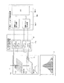
図5は本発明のビームモニタシステムの第1の実施形態におけるチャンネルのグループ化処理接続の一例を示す概略図、図6は本発明のビームモニタシステムの第1の実施形態における置換接続の一例を示す概略図、図7は本発明のビームモニタシステムの第1の実施形態における置換接続の一例を示す概略図、図8は本発明のビームモニタシステムの第1の実施形態におけるチャンネルグループ化モニタシステムの概略図、図9は本発明のビームモニタシステムの第1の実施形態における置換接続の一例を示す概略図、図10は本発明のビームモニタシステムの第1の実施形態における置換接続の一例を示す概略図、図11は本発明のビームモニタシステムの第1の実施形態におけるチャンネルグループ化モニタシステムの概略図、図12は本発明のビームモニタシステムの第1の実施形態におけるチャンネルグループ化モニタシステムの正常時における出力分布を示す図、図13は本発明のビームモニタシステムの第1の実施形態におけるチャンネルグループ化モニタシステムの異常時における出力分布を示す図、図14は本発明のビームモニタシステムの第1の実施形態におけるチャンネルグループ化モニタシステムの異常時における照射位置特定の概念図である。
Next, a beam position and beam width measurement method using the downstream beam monitor system of this embodiment will be described with reference to FIGS.
FIG. 5 is a schematic diagram showing an example of channel grouping processing connection in the first embodiment of the beam monitor system of the present invention. FIG. 6 is an example of replacement connection in the first embodiment of the beam monitor system of the present invention. FIG. 7 is a schematic diagram showing an example of replacement connection in the first embodiment of the beam monitor system of the present invention. FIG. 8 is a channel grouping monitor system in the first embodiment of the beam monitor system of the present invention. FIG. 9 is a schematic diagram showing an example of replacement connection in the first embodiment of the beam monitor system of the present invention. FIG. 10 is an example of replacement connection in the first embodiment of the beam monitor system of the present invention. FIG. 11 is a schematic diagram of the channel grouping monitor system in the first embodiment of the beam monitor system of the present invention, and FIG. FIG. 13 is a diagram showing an output distribution in a normal state of the channel grouping monitor system according to the first embodiment of the beam monitor system of the present invention. FIG. 13 is a diagram of the channel grouping monitor system according to the first embodiment of the beam monitor system of the present invention. FIG. 14 is a conceptual diagram of specifying an irradiation position at the time of abnormality of the channel grouping monitor system according to the first embodiment of the beam monitor system of the present invention.
本実施形態の下流ビームモニタ11dは、図3に示すように、X電極および電流・周波数変換器23を有するX軸ビームモニタ11d1と、Y電極および電流・周波数変換器23を有するY軸ビームモニタ11d2とを備える。X軸ビームモニタ11d1から信号処理装置22の間の構成は、Y軸ビームモニタ11d2の場合と同様の構成であるため、ここではX軸ビームモニタ11d1を例に説明する。X軸ビームモニタ11d1は、例えば、768本のワイヤ電極(X電極)が等間隔に張られた構成であり、768チャンネルを有する構成とする。
As shown in FIG. 3, the
図5に示すように、全チャンネルを隣り合う32チャンネル(ch)毎に区分1〜区分24まで24区分に分割する。すなわち、X軸ビームモニタ11d1は、隣り合う複数のワイヤ電極(本実施形態では、32チャンネルのワイヤ電極)を一つの区分とした、複数の区分(本実施形態では、24の区分)で構成される。このように一つの区分は、隣り合う複数のワイヤ電極で構成される。
X軸ビームモニタ11d1を構成するワイヤ電極を、設置位置に関する物理的な並びで、端から順番にチャンネル1,2,3,4・・・768と示した場合、区分1がチャンネル1〜32、区分2がチャンネル33〜64、‥‥、区分23がチャンネル705〜736、区分24がチャンネル737〜768である。
また、本実施形態では、隣り合う4つの区分を一つのグループとする。すなわち、区分1〜4をグループ1、区分5〜8をグループ2、区分9〜12をグループ3、区分13〜16をグループ4、区分17〜20をグループ5、区分21〜24をグループ6とする。ここで、一つのグループを構成する複数のワイヤ電極の端から端までの幅が、照射予定の荷電粒子ビームのビーム幅よりも大きくなるように一つのグループを構成し、ビーム位置およびビーム幅の計算に必要なビーム分布は(1グループ内の区分数−1)区分内に現れるものとする。
As shown in FIG. 5, all channels are divided into 24 sections from
When the wire electrodes constituting the X-axis beam monitor 11d1 are shown as
In the present embodiment, four adjacent sections are set as one group. That is,
図5において、グループ1に属する区分1乃至区分4の各チャンネル(1ch〜128ch)は電流・周波数変換器23に接続される。信号処理装置22は、電流・周波数変換器23と同数のパルスカウンタを有しており、下流ビームモニタ監視制御装置8b2内の積算パルス取込装置に接続されている。信号処理装置22は、X軸ビームモニタ11d1の1つのグループに属するワイヤ電極の数(本実施形態では128個)と、Y軸ビームモニタ11d2の1つのグループに属するワイヤ電極の数(本実施形態で128個)とを足し合わせた数(本実施形態では256個)のパルスカウンタを有する。信号処理装置22は、X軸ビームモニタ11d1を構成する各々のグループから選択された一つのワイヤ電極から出力される検出信号を同一の配線から電流・周波数変換器23の1つの入力点へ入力するように、グループに属するワイヤ電極と同数の配線によって接続される。このように、電流・周波数変換器23およびモニタ信号処理装置22はグループ1の全信号(128ch×2)を処理演算できるものであればよい。
In FIG. 5, each channel (1ch to 128ch) of
本実施形態の接続の方式を説明すると、図5に示すように、ある区分に属する各々のワイヤ電極は、他のグループに属する区分のいずれか一つのワイヤ電極とそれぞれ同一の配線によって電流・周波数変換器23を介して信号処理装置22に接続される。
例えば、グループ2に属する区分5の129ch〜160chを構成するそれぞれのワイヤ電極は、区分1の1ch〜32chを構成するワイヤ電極のいずれか一つに接続される。グループ3に属する区分9の257ch〜288chを構成するそれぞれのワイヤ電極は、区分1の1ch〜32chを構成するワイヤ電極のいずれか一つに接続される。グループ4に属する区分13を構成するそれぞれのワイヤ電極は、区分1の1ch〜32chを構成するワイヤ電極のいずれか一つに接続される。グループ5に属する区分17の513ch〜544chを構成するそれぞれのワイヤ電極は、区分1の1ch〜32chを構成するワイヤ電極のいずれか一つに接続される。グループ6に属する区分21の641ch〜672chを構成するそれぞれのワイヤ電極は、区分1の1ch〜32chを構成するワイヤ電極のいずれか一つに接続される。
上記と同様に、グループ1の区分2,3,4を構成するワイヤ電極とは、グループ2の区分6,7,8を構成するワイヤ電極、グループ3の区分10,11,12を構成するワイヤ電極、グループ4の区分14,15,16を構成するワイヤ電極、グループ5の区分18,19,20を構成するワイヤ電極、グループ6の区分22,23,24を構成するワイヤ電極が各々接続される。
The connection system of this embodiment will be described. As shown in FIG. 5, each wire electrode belonging to a certain section is connected to the current / frequency by the same wiring as any one of the wire electrodes belonging to the other group. The
For example, each wire electrode constituting the 129 ch to 160 ch of the
Similarly to the above, the wire electrodes constituting the
このように、複数グループのワイヤ電極同士を接続することで、グループ内のワイヤ電極1点がグループ数分同じ電流・周波数変換器23に接続される構成となる。
In this way, by connecting a plurality of groups of wire electrodes, one wire electrode in the group is connected to the same current /
また、このように、グループ間の接続方法を、区分同士では、区分の物理的並びの順に(グループ2の区分5とグループ3の区分9と、…とグループ6の区分22がグループ1の区分1に接続されるように)接続する構成をとることと、ビーム分布を(1グループ内の区分数−1)区分内に収めることで、複数グループにわたるビーム照射の場合の電流・周波数変換器23に入力される計測データの重なり合いを防止できる。
この際、区分内のワイヤ電極の接続方法は、区分内の物理的並びのままとせず、グループ固有の並びとしてワイヤ電極同士を接続することで、ワイヤ電極で計測されるビームの分布形状を電流・周波数変換器23の入力でグループ固有の分布形状にできる。これにより、分布形状から、どのワイヤ電極のグループへのビーム照射が行われたかを判断できる。以下に、この接続方法の詳細を示す。
Further, in this way, the connection method between the groups is determined in the order of the physical order of the sections (
At this time, the connection method of the wire electrodes in the section does not keep the physical arrangement in the section, but connects the wire electrodes as a group-specific arrangement so that the distribution shape of the beam measured by the wire electrodes can be changed. A group-specific distribution shape can be obtained by inputting the
また、区分5の129ch〜160chは区分1の1ch〜32chに接続されるが、この時、図5に示すように、区分5の各チャンネルは置換接続P1で接続先を置換して接続される。また、同じグループ2に属する区分6,7,8の各チャンネルも同様に置換接続P1で区分2,3,4の各チャンネルへ接続される。
グループ3の区分9は置換接続P1と異なる置換接続P2で、区分1の各チャンネルへ、同様に区分10,11,12の各チャンネルも置換接続P2で区分2,3,4の各チャンネルへ接続する。
グループ4の区分13,14,15,16はP1およびP2と異なる置換接続P3によりそれぞれ区分1,2,3,4へ、グループ5の区分17,18,19,20はP1、P2およびP3と異なる置換接続P4でそれぞれ区分1,2,3,4へ、グループ6の区分21,22,23,24はP1、P2、P3およびP4と異なる置換接続P5でそれぞれ区分1,2,3,4へ接続される。
このように、グループ毎に異なる置換接続によって、ある区分に属するワイヤ電極と他のグループの区分に属するワイヤ電極とを接続する。
In addition, 129ch to 160ch of
Section 9 of
In this way, wire electrodes belonging to a certain section are connected to wire electrodes belonging to a section of another group by different replacement connections for each group.
次に置換接続P1〜P5の中身の一例を図6乃至図10を用いて説明する。以下、1区分に32chが含まれ、1区間を4chとして置換接続を適用する場合の例を示す。 Next, an example of the contents of the replacement connections P1 to P5 will be described with reference to FIGS. Hereinafter, an example will be described in which 32 channels are included in one section and replacement connection is applied with one section being 4 channels.
まず、図6に示すように、1区分を複数の区間に分割して(例えば区分1を分割区間1〜8、以下区分2〜24に対しても同様に区間1〜8に分割する)、その区間を単位として、区間を入れ替える置換を行う。
例えば、置換接続P1は区間1と3、2と5、4と7,6と8を入れ替えた置換である。P2は1と4、2と7、3と5、6と8を入れ替え、P3は1と5、2と4、3と7、6と8を入れ替え、P4は1と7、2と6、3と5、4と8を入れ替え、P5は1と5、2と7、3と8、4と6を入れ替えた置換である。
First, as shown in FIG. 6, one section is divided into a plurality of sections (for example,
For example, the replacement connection P1 is a replacement in which the
更に、本実施形態では、図7乃至図10に示すように、計測位置での区分区間構成に対して、1区間内のチャンネルを若い方から(1)〜(4)と番号をつける。 Furthermore, in the present embodiment, as shown in FIGS. 7 to 10, the channels in one section are numbered as (1) to (4) from the younger with respect to the section structure at the measurement position.
まず、グループ1に対しては、図7のグループ1の接続構成に示すように、置換接続を実施せず、計測点のチャンネルの並びと同じとする。
First, for
ここで、図8に示すように、ビーム幅が7ch程度の細いビームの場合を考えると、足切りにより、計算の際にはガウス分布の両端の出力値の低い部分が無視され、計測位置幅に必要とされるビーム計測チャンネル数が1区間(4ch)内に収まる場合が考えられる。この場合には、ビームが照射されるグループとは異なる計測点グループの逆置換を実施してもビーム形状が崩れないため、電流・周波数変換器23、信号処理装置22を介し、下流ビームモニタ監視制御装置8b2に入力される分布形状を元に、どのグループへのビーム照射が行われたかを判断することが難しくなる。これを防ぐため、区間ごとの入替えだけでなく、区間内のチャンネルに対しても置換を行う必要がある。また、ガウスフィッティングも最小3chで計算できることも考慮すると、3chの出力値が離れた点になる、従って少なくとも2chが連続とならなければよいことになる。
Here, as shown in FIG. 8, when considering the case of a thin beam having a beam width of about 7 ch, the portion with low output values at both ends of the Gaussian distribution is ignored during calculation due to the cut off, and the measurement position width It is conceivable that the number of beam measurement channels required for the above is within one section (4 ch). In this case, since the beam shape does not collapse even if reverse substitution of a measurement point group different from the group irradiated with the beam is performed, downstream beam monitor monitoring is performed via the current /
このように、少なくとも2chが置換前後の配置で異なればよいので、図9のグループ2の場合に示すように4chで区間に分ける際に、ch(1)、(2)、(3)、(4)のそれぞれの点に別々の(循環)置換を行う。
Thus, since at least 2ch only needs to be different in the arrangement before and after replacement, when dividing into sections by 4ch as shown in the case of
具体的には、グループ2の区分5〜8に対しては、図9に示すように、計測点にて番号付けした(1)〜(4)に関して、奇数の番号に対しては置換を実施せず計測点のチャンネルの並びと同じとし、偶数の番号に対してはそれぞれの区間の同じ番号のチャンネルを同一区分内で循環的に入れ替えるような置換接続を適用する。
すなわち、(2)に対しては1区間隣の区間と循環的に入れ替える((2)の位置のデータを循環的に1区間分ずらす)接続構成とし、(4)に対しては3区間分隣の区間と循環的に入替えを行う((4)の位置のデータを循環的に3区間分ずらす)接続構成を適用している。これにより、置換前後のチャンネルの並びの関係が(1)固定、(2)1区間隣、(3)固定、(4)3区間隣となっている。
Specifically, as shown in FIG. 9, for
That is, for (2), it is connected to the section adjacent to one section cyclically (the data at the position of (2) is cyclically shifted by one section), and for (4), three sections are connected. A connection configuration is used in which replacement is performed cyclically with the adjacent section (the data at the position (4) is cyclically shifted by three sections). Thereby, the relationship of the arrangement of the channels before and after replacement is (1) fixed, (2) adjacent to one section, (3) fixed, and (4) adjacent to three sections.
グループ3やグループ4などの他のグループにも、グループ2に適用したようなワイヤ接続をグループ毎にそれぞれ独立となるような(循環)置換を適用する。
例えば、図10に示すように、クループ3の区分9−12は、(1)固定、(2)2区間隣、(3)固定、(4)4区間隣となるよう(循環)置換を適用する。グループ4の区分13−16は、(1)固定、(2)3区間隣、(3)固定、(4)5区間隣となるよう(循環)置換を適用する。グループ5の区分17−20は、(1)固定、(2)4区間隣、(3)固定、(4)6区間隣となるよう(循環)置換を適用する。グループ6の区分21−24は、(1)固定、(2)5区間隣、(3)固定、(4)7区間隣となるよう(循環)置換を適用する。
これにより、区間内の連続する4つの計測チャンネルのうち隣り合う2つのチャンネルが物理的に連続しないように電流・周波数変換器23のチャンネルにワイヤ電極が接続されている。
For other groups such as the
For example, as shown in FIG. 10, the group 3-12 of the
Thereby, the wire electrode is connected to the channel of the current /
なお、図9および図10においては、(2),(4)の右下付きの数字が(循環)置換前の区間番号に相当する。 In FIG. 9 and FIG. 10, the numbers with the lower right in (2) and (4) correspond to the section numbers before (circulation) replacement.
次に、本実施形態での動作について説明する。 Next, the operation in this embodiment will be described.
信号処理装置22は、ワイヤ電極から検出信号を受け取ると、入力された検出信号がいずれのグループに属するワイヤ電極の検出信号であるかを示すグループ情報を求める。また、信号処理装置22は、検出信号を置換接続の情報に基づいて並び替えて(逆置換して)、ワイヤ電極を通過した荷電粒子ビームのビーム形状を求める。信号処理装置22は、求めたグループ情報およびビーム形状の情報を含む処理信号を下流ビームモニタ監視制御装置8b2の積算パルス取り込み装置8b2−1を介してCPU8b2−2に送信する。なお、信号処理装置22に備えられた記憶装置が、受信した検出信号を記憶し、記憶された検出信号を処理して処理信号を送信するようにしても良い。下流ビームモニタ監視制御装置8b2は、受信したビーム形状の情報およびグループ情報に基づいて、ワイヤ電極を通過した荷電粒子ビームのビーム位置およびビーム幅を求める。下流ビームモニタ監視制御装置8b2は、求めたビーム位置およびビーム幅を操作端末40に備えられた表示画面に表示させる。
When the
まず、図11において、正常時50aのように治療計画装置6で定めた目標通りにビーム照射できた場合を考える。
First, in FIG. 11, let us consider a case where beam irradiation can be performed according to the target set by the treatment planning device 6 as in the
区分19にビームが照射されたとする。この場合、区分19で検出される値は置換接続P4で置換されてから区分3に接続され、電流・周波数変換器23に送られる。この時の出力は、図12に示すように、出力分布(正常時)51aのようにP4による置換の影響でガウス分布が得られない。なお、図12では、理解しやすさのため、区間内の循環置換については既に逆変換した後の例を示している。
しかし、ビームをどこに照射するかは予め治療計画装置6により定められている。このため、治療計画装置6で作成された治療計画データに基づき、実照射ビームが、P1〜P5のどの置換接続を実施されたかも予測することができる。
Assume that the beam is irradiated to the section 19. In this case, the value detected in section 19 is replaced by
However, the treatment planning apparatus 6 determines where the beam is irradiated. For this reason, based on the treatment plan data created by the treatment plan device 6, it can be predicted which replacement connection of P1 to P5 is performed by the actual irradiation beam.
本実施形態では、区分19を計画目標位置としているため、P4によって置換されたことが予測できる。従って、モニタ信号処理装置22でP4の逆置換を行うことで逆置換分布(正常時)52aのようにガウス分布が得られる。ガウス分布が得られることで実際の照射位置と計画データでの照射位置が一致していることが明確になり、ビーム位置およびビーム幅を正確に求めることができる。また、電流・周波数変換器23およびモニタ信号処理装置22は1グループ内のチャンネル分しか必要としないため、低コストのモニタシステムを実現できる。
In this embodiment, since the section 19 is the planned target position, it can be predicted that the section 19 has been replaced by P4. Therefore, a Gaussian distribution is obtained as in the reverse replacement distribution (normal) 52a by performing reverse replacement of P4 in the monitor
次に、図11の異常時50bに示すように、実際のビーム照射が治療計画に基づく目標照射位置と異なる場合を考える。
例えば、目標照射位置が区分19であるのに対し、実際のビーム照射位置が区分7となった場合について考える。
Next, consider the case where the actual beam irradiation is different from the target irradiation position based on the treatment plan, as shown in the
For example, let us consider a case where the target irradiation position is in section 19 while the actual beam irradiation position is in section 7.
このような場合、図13に示すように、区分7で検出された値はP1により置換された後に電流・周波数変換器23に送られ、出力分布(異常時)51bが得られる。しかし、治療計画に基づく目標照射位置は区分19であるため、出力に対してモニタ信号処理装置22ではP4の逆置換が行われ、その結果得られる分布は逆置換出力分布(異常時)52bとなり、ガウス分布を得ることはできない。
In such a case, as shown in FIG. 13, the value detected in section 7 is sent to the current /
この場合は、下流ビームモニタ監視制御装置8b2は、ビームのエラー(位置、幅の異常状態または演算不可能)を示すエラー信号を中央制御装置5に出力する。エラー信号を受信した中央制御装置5は、加速器・輸送系制御システム7にビーム停止信号を出力し、円形加速器16から出射する荷電粒子ビームを停止させる。
In this case, the downstream beam monitor monitoring control device 8b2 outputs an error signal indicating a beam error (abnormal state of position or width or calculation impossible) to the
また、下流ビームモニタ監視制御装置8b2は、照射位置特定処理60を実施する。これにより、荷電粒子ビームを異常照射した位置を特定する。
照射位置特定処理60として、例えば、図14に示すように、異常照射が起こった出力分布に対し、P1の逆置換、P2の逆置換、…と順次逆置換を実施し、ガウス分布が得られる置換接続を特定する。これにより、どのチャンネルに異常照射したかを正確に知ることができる。本実施形態の場合はP1の逆置換でガウス分布が得られるため、グループ2の特定のチャンネルに異常照射したことが明確になる。
Further, the downstream beam monitor monitoring control device 8b2 performs the irradiation
As the irradiation
また、ビーム幅が変化した場合には、ある範囲の任意のビーム幅に対して置換接続を考えたシミュレーションを行い、その結果と実照射分布とを比較することでビーム位置およびビーム幅の特定が可能である。
このシミュレーションとは、計算機上で実際のビームモニタシステム中のセンサ部からパルス発生器入力前までを模擬し、異常照射時の実照射分布をガウス分布と想定して、ビーム位置,ビーム幅をある値からある値まで一定の間隔でそれぞれ変化させた入力を与え、ビーム位置から決まる置換接続が適用されたそれぞれの計算機出力結果と実照射の信号処理装置22、もしくは下流ビームモニタ制御装置に入力される分布を比較し一致するものを求め、異常照射時のビーム位置,ビーム幅を求めるものである。
In addition, when the beam width changes, a simulation considering replacement connection is performed for an arbitrary beam width in a certain range, and the result and the actual irradiation distribution are compared to identify the beam position and beam width. Is possible.
This simulation simulates the actual beam distribution at the time of abnormal irradiation on the computer from the sensor part in the actual beam monitor system to before the pulse generator input. Each input is changed from a value to a certain value at regular intervals, and each computer output result to which a replacement connection determined from the beam position is applied and the actual irradiation
本実施形態では、理解しやすいようグループ内にビームが収まる場合を説明してきたが、その他に複数のグループを含む位置への照射の場合が考えられる。この場合においても、区分ごとに区分の属するグループの置換が実施されるため、区分単位でそれぞれの区分が属するグループの置換情報を元に逆置換を実施することで、複数グループを含む位置でのビーム分布であっても、正確なビームの位置、幅の特定、およびビーム位置幅の正常、異常の判断が可能である。 In this embodiment, the case where the beam fits in the group has been described for easy understanding, but the case of irradiation to a position including a plurality of groups can be considered. Even in this case, because the replacement of the group to which the section belongs is performed for each section, by performing reverse replacement based on the replacement information of the group to which each section belongs in the section unit, at the position including multiple groups Even with the beam distribution, it is possible to accurately determine the position and width of the beam and to determine whether the beam position width is normal or abnormal.
本実施形態のビームモニタシステムを備える粒子線照射システムは、ワイヤをグループ化し、グループ毎に異なる接続方法を実施したシンプルな構成のマルチワイヤ形モニタのビームモニタシステムにおいて、荷電粒子ビームの位置およびビーム幅の算出に利用するチャンネルを限定している。このため、全チャンネルに対応した増幅器および信号処理装置を準備する必要がない。
本実施形態のビームモニタシステムと、従来のビームモニタシステムを比較する。
The particle beam irradiation system including the beam monitor system of this embodiment is a beam monitor system of a multi-wire monitor having a simple configuration in which wires are grouped and different connection methods are performed for each group. The channels used to calculate the width are limited. For this reason, it is not necessary to prepare an amplifier and a signal processing device corresponding to all channels.
The beam monitor system of this embodiment is compared with a conventional beam monitor system.
従来のビームモニタシステムの場合、X軸ビームモニタが768本のワイヤ電極で構成される場合、その後段に配置されるパルス発生器およびパルスカウンタは、ワイヤ電極の数(チャンネル数)と同数の768個ずつそれぞれ設置される。Y軸ビームモニタが768本のワイヤ電極で構成される場合、同様に、その後段に配置されるパルス発生器およびパルスカウンタはそれぞれ768個ずつ設置される。このため、従来のモニタシステムは、768個のパルス発生器および768個のパルスカウンタを有する。 In the case of the conventional beam monitor system, when the X-axis beam monitor is composed of 768 wire electrodes, the number of pulse generators and pulse counters arranged in the subsequent stage is 768 which is the same as the number of wire electrodes (the number of channels). Each one is installed. When the Y-axis beam monitor is composed of 768 wire electrodes, similarly, 768 pulse generators and pulse counters arranged in the subsequent stage are installed. For this reason, the conventional monitoring system has 768 pulse generators and 768 pulse counters.
このような従来のモニタシステムに対し、本実施形態のビームモニタシステムの場合、X軸ビームモニタが768本のワイヤ電極で構成される場合であっても、ワイヤ電極の数(チャンネル数)よりも十分少ない数である、128個のパルス発生器および128個のパルスカウンタを備える構成によって、荷電粒子ビームのビーム位置およびビーム幅を求めることができる。 In contrast to such a conventional monitor system, in the case of the beam monitor system of the present embodiment, even if the X-axis beam monitor is composed of 768 wire electrodes, the number of wire electrodes (number of channels) is more than that. A sufficiently small number of 128 pulse generators and 128 pulse counters can be used to determine the beam position and beam width of the charged particle beam.
また、本実施形態のビームモニタシステムは、電荷収集電極が隣り合う複数のワイヤ電極を一つのグループとした複数のグループで構成される。また、グループの各々から選択された一つのワイヤ電極から出力される検出信号を同一の配線から入力するように、グループに属するワイヤ電極と同数の配線によって全てのワイヤ電極と、あるまとまった連続する計測チャンネルに対して、2チャンネルは物理的に連続しないように信号処理装置のチャンネルに接続する。さらに、信号処理装置22は、入力された検出信号がいずれのグループに属するワイヤ電極の検出信号であるかを示すグループ情報を求め、グループ情報を含む処理信号をビームモニタ制御装置に出力し、ビームモニタ制御装置においてワイヤ電極を通過した荷電粒子ビームの位置およびビーム幅を求める構成を有する。
そのため、シンプルな構成でモニタシステムを構築することができる。また、本実施形態によれば、ワイヤの接続方法をグループ毎に変更することで照射位置を正確に知ることができ、信頼性の高いモニタシステムを実現できる。
また、単純に区間を入れ替える置換を行うと、位置幅計算に必要とされるチャンネル数が区間内に収まるビーム幅の狭いビームが照射される場合に、分布形状が置換接続の有無、種類に関わらず変化しないために、計測位置でのビームの分布形状が置換接続後の電流・周波数変換器23でのビームの分布形状と一致して、誤照射ビームを検出できない可能性がある。しかし、本実施形態の置換接続の構成によれば、ビームの分布が最低限確認できる3ch程度の細いビームであっても、あるまとまった連続する計測チャンネルに対して、2チャンネルは物理的に連続しないように信号処理装置のチャンネルにワイヤ接続されていることによって計測位置でのビームの分布形状が置換接続によって崩れる。このため、計測位置でのビームの分布を信号処理装置22でグループ毎に必ず変化させることができ、位置幅計算にずれが生じ、誤った位置への照射を正確に検出することができる。
In addition, the beam monitor system according to the present embodiment includes a plurality of groups in which a plurality of wire electrodes adjacent to each other are arranged as one group. In addition, all the wire electrodes are arranged in a continuous manner by the same number of wires as the wire electrodes belonging to the group so that detection signals output from one wire electrode selected from each group are input from the same wire. For the measurement channel, the two channels are connected to the channel of the signal processing device so as not to be physically continuous. Further, the
Therefore, a monitor system can be constructed with a simple configuration. Further, according to the present embodiment, the irradiation position can be accurately known by changing the wire connection method for each group, and a highly reliable monitor system can be realized.
In addition, if replacement is performed simply by exchanging sections, the distribution shape is related to the presence / absence of replacement connection and the type when a beam with a narrow beam width within which the number of channels required for position width calculation is within the section is irradiated. Therefore, the beam distribution shape at the measurement position coincides with the beam distribution shape in the current /
これにより、本実施形態のモニタシステムは患者に対する照射線量・照射位置を正確に管理することが可能となる。 Thereby, the monitor system of this embodiment becomes possible [managing the irradiation dose and irradiation position with respect to a patient correctly].
本実施形態のビームモニタシステムを備える粒子線照射システムは、特に、細い荷電粒子ビームを走査して照射する方式に対して有効である。すなわち、精度のよい照射を行うためには細径ビームが必要になり、ビームプロファイルを計測するマルチワイヤ形モニタの単位長さあたりのワイヤ数が増加する方向となるが、荷電粒子ビームが同時に照射されるワイヤは全ワイヤのごく一部である。本実施形態のビームモニタシステムは、荷電粒子ビームが同時に照射される範囲に相当する数のワイヤ信号だけに信号処理を行う方式として、照射範囲に相当する数のワイヤに、その他のワイヤを接続する構成であるため、低コストかつ高い信頼性を実現できる。 The particle beam irradiation system including the beam monitor system of the present embodiment is particularly effective for a method of scanning and irradiating a thin charged particle beam. That is, in order to perform irradiation with high accuracy, a thin beam is required, and the number of wires per unit length of the multi-wire monitor for measuring the beam profile increases, but the charged particle beam is irradiated simultaneously. The wires that are made are a small part of the total wire. The beam monitor system of the present embodiment connects other wires to the number of wires corresponding to the irradiation range as a method of performing signal processing only on the number of wire signals corresponding to the range irradiated with the charged particle beam simultaneously. Because of the configuration, low cost and high reliability can be realized.
本実施形態のビームモニタシステムを備える粒子線照射システムは、ワイヤ電極の接続方法をグループ毎に変更するため、照射位置を正確に知ることができ、信頼性の高いモニタシステムを実現することができる。 Since the particle beam irradiation system including the beam monitor system according to the present embodiment changes the wire electrode connection method for each group, the irradiation position can be accurately known, and a highly reliable monitoring system can be realized. .
<第2の実施形態>
本発明のビームモニタシステムおよび粒子線照射システムの第2の実施形態を図15および図16を用いて説明する。
図15は本発明のビームモニタシステムの第2の実施形態におけるフィッティング関数と実測値の分布の一例を示す図、図16は本発明のビームモニタシステムの第2の実施形態におけるフィッティング関数と実測値の分布の他の例を示す図である。
<Second Embodiment>
A second embodiment of the beam monitor system and particle beam irradiation system of the present invention will be described with reference to FIGS. 15 and 16.
FIG. 15 is a diagram showing an example of the distribution of the fitting function and the actual measurement value in the second embodiment of the beam monitor system of the present invention, and FIG. 16 is the fitting function and the actual measurement value in the second embodiment of the beam monitor system of the present invention. It is a figure which shows the other example of distribution of.
第2の実施形態に係るビームモニタシステムは、上流ビームモニタ監視制御装置8b1または下流ビームモニタ監視制御装置8b2において、適切な照射であると判断する条件として、ビーム位置,ビーム幅の算出結果が許容値以下になる条件に加え、計測結果の分布から求められるフィッティング関数と実測値とのチャンネル毎の差分の二乗和の平均値(分散値)が許容値以下になる場合に適切な照射であると判断する条件を適用する。
上記上流ビームモニタ監視制御装置8b1または下流ビームモニタ監視制御装置8b2における判断条件以外の構成は第1の実施形態のビームモニタシステムおよび粒子線照射システムと略同じであるため、詳細は省略する。
In the beam monitor system according to the second embodiment, the upstream beam monitor monitoring control device 8b1 or the downstream beam monitor monitoring control device 8b2 accepts the calculation results of the beam position and beam width as conditions for determining appropriate irradiation. In addition to the conditions below the value, the irradiation is appropriate when the average value (dispersion value) of the sum of squares of the difference between the fitting function obtained from the distribution of measurement results and the measured value for each channel is below the allowable value. Apply the conditions to judge.
Since the configuration other than the determination conditions in the upstream beam monitor monitoring control device 8b1 or the downstream beam monitor monitoring control device 8b2 is substantially the same as that of the beam monitor system and particle beam irradiation system of the first embodiment, the details are omitted.
次に、本実施形態での動作について、第1の実施形態と同様に、下流ビームモニタ監視制御装置8b2を用いて説明する。 Next, the operation in the present embodiment will be described using the downstream beam monitor monitoring control device 8b2 as in the first embodiment.
信号処理装置22は、ワイヤ電極から検出信号を受け取ると、入力された検出信号がいずれのグループに属するワイヤ電極の検出信号であるかを示すグループ情報を求める。また、信号処理装置22は、検出信号を置換接続の情報に基づいて並び替えて、ワイヤ電極を通過した荷電粒子ビームのビーム形状を求める。第1の実施形態のように、下流ビームモニタ監視制御装置8b2で本処理を実施する構成としてもよいものとする。
When the
下流ビームモニタ監視制御装置8b2は、受信したビーム形状の情報に基づいて、ワイヤ電極を通過した荷電粒子ビームのビーム幅を求める。また、下流ビームモニタ監視制御装置8b2は、受信したビーム形状の情報およびグループ情報に基づいて、ワイヤ電極を通過した荷電粒子ビームのビーム位置を求める。 The downstream beam monitor monitoring controller 8b2 obtains the beam width of the charged particle beam that has passed through the wire electrode based on the received beam shape information. Further, the downstream beam monitor monitoring controller 8b2 obtains the beam position of the charged particle beam that has passed through the wire electrode based on the received beam shape information and group information.
更に、下流ビームモニタ監視制御装置8b2は、位置幅計算時に、フィッティング関数と実測値との差分の二乗和の平均値(分散値)を演算する。
分散値σ2は、ビーム位置幅計算に用いるチャンネル数をn、計測チャンネルをxとしてフィッティング関数をf(x)、実測値をM(x)と表すと、次式(1)

The dispersion value σ 2 is expressed by the following equation (1) when n is the number of channels used for beam position width calculation, x is a measurement channel, and f (x) is a fitting function and M (x) is an actual measurement value.
その上で、分散値σ2がある値(許容値)以下(σ2≦Const.(Const.はある一定値を表す))のときは正常なビーム位置での照射であると判定し、分散値σ2が許容値より大きいときは正常でないビーム位置での照射であると判定する。下流ビームモニタ監視制御装置8b2は、ビームのエラーを示すエラー信号を中央制御装置5に出力する。
In addition, when the dispersion value σ 2 is equal to or smaller than a certain value (allowable value) (σ 2 ≦ Const. (Const. Represents a certain value)), it is determined that the irradiation is performed at a normal beam position, and the dispersion is When the value σ 2 is larger than the allowable value, it is determined that the irradiation is performed at an abnormal beam position. The downstream beam monitor monitoring controller 8b2 outputs an error signal indicating a beam error to the
具体的には、図15に示すように、正常なビーム位置での逆置換後の計算の場合、計算処理部にて逆置換を実施した後の実測値111aは、フィッティング関数112a上もしくは近傍に実測値が現れる。
この場合は、フィッティング関数112aと実測値111aとの差分は非常に小さくなり、分散値も許容値以下となる。そのため、下流ビームモニタ監視制御装置8b2は正常なビーム位置での照射であると判定し、下流ビームモニタ監視制御装置8b2は、求めたビーム位置およびビーム幅を操作端末40に備えられた表示画面に表示させ、荷電粒子ビームのビーム位置およびビーム幅を表示する。
Specifically, as shown in FIG. 15, in the case of calculation after reverse replacement at a normal beam position, the actually measured value 111a after reverse replacement is performed on or near the
In this case, the difference between the
これに対し、図16に示すように、誤ったビーム位置での逆置換後の計算では、実測値の分布がばらけるにも関わらず、フィッティング関数112bが正常なビームを表す関数に非常に類似する場合がある。
この場合は、フィッティング関数112bからの実測値111bのずれが大きくなるため、分散値は許容値より大きくなる。そのため、下流ビームモニタ監視制御装置8b2は正常なビーム位置での照射でないと判定し、ビームのエラーを示すエラー信号を中央制御装置5に出力する。また、下流ビームモニタ監視制御装置8b2は、照射位置特定処理60を実施する。
On the other hand, as shown in FIG. 16, in the calculation after reverse replacement at the wrong beam position, the fitting function 112b is very similar to the function representing a normal beam, although the distribution of the actual measurement values varies. There is a case.
In this case, since the deviation of the actual measurement value 111b from the fitting function 112b becomes large, the variance value becomes larger than the allowable value. Therefore, the downstream beam monitor monitoring controller 8b2 determines that the irradiation is not performed at a normal beam position, and outputs an error signal indicating a beam error to the
本発明のビームモニタシステムおよび粒子線照射システムの第2の実施形態においても、前述したビームモニタシステムおよび粒子線照射システムの第1の実施形態とほぼ同様な効果が得られる。
すなわち、シンプルな構成でモニタシステムを構築することができ、低コストかつ信頼性の高いモニタシステムを実現することができる。
Also in the second embodiment of the beam monitor system and particle beam irradiation system of the present invention, substantially the same effects as in the first embodiment of the beam monitor system and particle beam irradiation system described above can be obtained.
That is, a monitor system can be constructed with a simple configuration, and a low-cost and highly reliable monitor system can be realized.
また、第1の実施形態で説明したような区分内を数チャンネル単位で全体的に入れ替えるような置換を実施した場合で、信号処理部の分布形状を見ることで誤照射の検出は容易に可能である。しかし、ビーム位置幅の計算上で分布のフィッティング処理を行っているため、全体的にチャンネルを入れ替える置換を実施した分布において、フィッティングの仕方によっては誤ったビーム位置に対するフィッティング関数であっても正しいビーム位置に対するフィッティング関数に近いものとして求められる可能性がある。
これに対し、位置および幅の算出結果が許容値以下であるかの判断条件に加えて、分布から求められるフィッティング関数と実測値とのチャンネル毎の差分の分散値が許容値以下の場合に適切な照射であると判断する条件を加えることにより、実測値と計算に使用するフィッティング関数とのずれを評価し、適切なビーム位置であるかどうかをより正確に判断することができ、計算上で誤照射を正確に検出するモニタシステムを実現することができる。
In addition, when performing replacement such as replacing the entire section in units of several channels as described in the first embodiment, it is possible to easily detect erroneous irradiation by looking at the distribution shape of the signal processing unit. It is. However, because the distribution fitting process is performed in the calculation of the beam position width, in the distribution in which the replacement is performed to replace the channel as a whole, the correct beam even if the fitting function for the wrong beam position is used depending on the fitting method. There is a possibility that it may be obtained as close to the fitting function for the position.
On the other hand, in addition to the condition for determining whether the position and width calculation results are below the allowable value, it is appropriate when the variance value of the difference between the fitting function obtained from the distribution and the measured value for each channel is below the allowable value. By adding the condition for judging that the irradiation is correct, it is possible to evaluate the deviation between the measured value and the fitting function used for the calculation, and more accurately determine whether the beam position is appropriate. A monitor system that accurately detects erroneous irradiation can be realized.
なお、上述の実施形態では、信号処理装置22における適切な照射であると判断する条件として分散値を判断の条件の基準として誤照射検出を行ったが、判断条件はこれに限られず、それぞれのチャンネルに対するフィッティング関数と実測値との差分を判断の条件の基準とすることができる。
In the above-described embodiment, the mis-irradiation detection is performed using the dispersion value as a criterion for the determination condition as a condition for determining the appropriate irradiation in the
<第3の実施形態>
本発明のビームモニタシステムおよび粒子線照射システムの第3の実施形態を図17を用いて説明する。
図17はラスタースキャン方式による荷電粒子ビーム照射の制御のフローチャート図である。
<Third Embodiment>
A third embodiment of the beam monitor system and particle beam irradiation system of the present invention will be described with reference to FIG.
FIG. 17 is a flowchart of the charged particle beam irradiation control by the raster scan method.
第1の実施形態はスポットスキャニング照射法におけるビーム位置およびビーム幅を監視するビームモニタシステムを備える粒子線照射システムであるのに対し、本実施形態の粒子線照射システムはラスタースキャニング照射法におけるビーム位置およびビーム幅を監視するビームモニタシステムを備える。
本実施形態の粒子線照射システムは、患者13の患部をビーム進行方向に複数のレイヤーに分割し、各レイヤーにおいて荷電粒子ビームの照射を継続したまま(ビームONのまま)、荷電粒子ビームを走査するラスタースキャニング照射法におけるビーム位置およびビーム幅を監視するビームモニタシステムを備える。
The first embodiment is a particle beam irradiation system including a beam monitor system that monitors the beam position and beam width in the spot scanning irradiation method, whereas the particle beam irradiation system of the present embodiment is a beam position in the raster scanning irradiation method. And a beam monitor system for monitoring the beam width.
The particle beam irradiation system of this embodiment divides the affected part of the patient 13 into a plurality of layers in the beam traveling direction, and scans the charged particle beam while continuing irradiation of the charged particle beam in each layer (with the beam ON). A beam monitor system for monitoring a beam position and a beam width in the raster scanning irradiation method.
以下、本実施形態の粒子線照射システムについて、図17を参照して、第1の実施形態と異なる構成、動作を説明する。 Hereinafter, the configuration and operation of the particle beam irradiation system of the present embodiment, which are different from those of the first embodiment, will be described with reference to FIG.
治療の準備が完了すると、医師は操作端末40の入力装置から治療開始信号を入力する。
治療開始信号を入力した中央制御装置5は、加速器・輸送系制御システム7に指令信号を送信する。
加速器・輸送系制御システム7は、最初に照射するレイヤー(最初に照射するビームエネルギー情報)に相当する運転パラメータを円形加速器16およびビーム輸送系2に設定する。円形加速器16およびビーム輸送系2の運転パラメータが設定されて準備完了すると(ステップS30)、走査電磁石電源制御装置8cは励磁電流パラメータに基づいて走査電磁石11bを励磁する(ステップS31A)。最初の照射位置に対応する励磁電流が走査電磁石11bに励磁された後、モニタ監視制御装置8bの線量監視制御装置8b3が、当該スポット位置に対する目標線量値に基づいてビーム線量の監視を開始し(ステップS32A)、照射準備が完了する。
When preparation for treatment is completed, the doctor inputs a treatment start signal from the input device of the
The
The accelerator / transport system control system 7 sets operation parameters corresponding to the layer to be irradiated first (beam energy information to be irradiated first) in the
中央制御装置5がビーム出射開始指令を送信すると(ステップS33)、加速器・輸送系制御システム7はイオン源を起動し、荷電粒子(陽子または重粒子)を生成する。前段加速器15は、イオン源からの荷電粒子を加速し、円形加速器16に出射する。円形加速器16は、荷電粒子ビームを更に加速する。周回する荷電粒子ビームは目標エネルギーまで加速され、円形加速器16からビーム輸送系2に出射される。荷電粒子ビームは、ビーム輸送系2を経てスキャニング照射装置3に到達する。さらに、荷電粒子ビームは、照射ノズル11内をビーム軸に沿って進行し、上流ビームモニタ11a,走査電磁石11b,線量モニタ11cおよび下流ビームモニタ11dを通過する。照射ノズル11から出射された荷電粒子ビームが患者13の患部に照射される。
When the
線量監視制御装置8b3は、線量モニタ11cで計測した計測データを受け取って演算処理して当該照射位置に対する照射線量を求めるとともに、最初の照射位置に対する照射線量値が目標線量値に達するまで荷電粒子ビームの照射を続ける。線量監視制御装置8b3は、照射線量値が目標線量値に達したと判断すると、中央制御装置5に対して照射満了信号を出力する(ステップS34)。
The dose monitoring controller 8b3 receives the measurement data measured by the
上流ビームモニタ11aで検出した第1検出データを上流ビームモニタ監視制御装置8b1で取り込み、下流ビームモニタ11dで検出した第2検出データを下流ビームモニタ監視制御装置8b2で取り込み、照射された荷電粒子ビームの位置およびビーム幅を求める(ステップS35A)。演算処理が終了し、ビームの位置およびビーム幅に異常がなければ(ビーム位置が許容ビーム位置の範囲内であり、ビーム幅が許容ビーム幅の範囲内と判断されれば)、照射満了した照射位置がレイヤー内での最後の照射位置であるか否かを判定する。最後の照射位置でないと判断された場合(Noの場合)、走査電磁石電源制御装置8cが励磁電流パラメータに基づいてスポット走査電磁石の設定を行い(ステップS35B)、モニタ監視制御装置8bがスポット線量目標値設定を行う(ステップS35C)。
ステップS34に戻り、照射満了した照射スポットがレイヤー内での最後のスポット位置であると判断されるまで(Yesと判断されるまで)、線量満了の判断ステップS34から最後のスポットであるか否かの判定までの制御フロー37Aを繰り返し行う。
The first detection data detected by the
Returning to step S34, whether or not it is the last spot from the dose expiration determination step S34 until it is determined that the irradiated irradiation spot is the last spot position in the layer (until determined to be Yes). The control flow 37A up to the determination is repeated.
レイヤー内の全てのスポットへの照射が完了すると、中央制御装置5は、照射完了したレイヤーが患者13に対する最後のレイヤーであるか否かを判断する(ステップS36A)。最後のレイヤーでない場合(Noの場合)、中央制御装置5は加速器・輸送系制御システム7に指令信号を送信する。加速器・輸送系制御システム7は、次に照射するレイヤーに相当する運転パラメータを円形加速器16およびビーム輸送系2に設定し、次の運転準備を開始する(ステップS30)。
When irradiation to all the spots in the layer is completed, the
この制御フロー38Aを全てのレイヤーが照射完了するまで繰り返す。全てのスポットおよび全てのレイヤーの照射が完了すると治療終了39となる。 This control flow 38A is repeated until all layers are irradiated. When irradiation of all the spots and all the layers is completed, the treatment ends 39.
上述のフローにおいて、上流ビームモニタ監視制御装置8b1および下流ビームモニタ監視制御装置8b2は、第1の実施形態と同様の処理を実施する。 In the above-described flow, the upstream beam monitor monitoring control device 8b1 and the downstream beam monitor monitoring control device 8b2 perform the same processing as in the first embodiment.
このように、本実施形態の粒子線照射システムは、荷電粒子ビームを出射させた状態で照射位置を変更して、患部に対してビーム照射するラスタースキャニング照射法を実現する。 As described above, the particle beam irradiation system according to the present embodiment realizes the raster scanning irradiation method in which the irradiation position is changed in a state where the charged particle beam is emitted and the affected part is irradiated with the beam.
本発明のビームモニタシステムおよび粒子線照射システムの第3の実施形態においても、前述したビームモニタシステムおよび粒子線照射システムの第1の実施形態とほぼ同様な効果が得られる。
すなわち、シンプルな構成でモニタシステムを構築することができ、低コストかつ信頼性の高いモニタシステムを実現することができる。
In the third embodiment of the beam monitor system and the particle beam irradiation system of the present invention, substantially the same effects as those of the first embodiment of the beam monitor system and the particle beam irradiation system described above can be obtained.
That is, a monitor system can be constructed with a simple configuration, and a low-cost and highly reliable monitor system can be realized.
なお、本実施形態の粒子線照射システムは、第2の実施形態のビーム位置およびビーム幅を監視するビームモニタシステムを備える粒子線照射システムにも適用することができる。 Note that the particle beam irradiation system of the present embodiment can also be applied to a particle beam irradiation system including a beam monitor system that monitors the beam position and beam width of the second embodiment.
<その他>
なお、本発明は上記の実施形態に限られず、種々の変形、応用が可能なものである。
<Others>
In addition, this invention is not restricted to said embodiment, A various deformation | transformation and application are possible.
例えば、モニタのチャンネル、区分、およびグループは任意の数で構成することができる。置換接続は、区間内のチャンネルに対して、奇数の場合は置換接続無し、偶数の場合はチャンネルごとに(循環)置換接続を実施するものとしたが、あるまとまった連続する計測チャンネルに対して、2チャンネルは物理的に連続しないように信号処理部のチャンネルにワイヤ接続される任意の接続方法で実施することができる。
For example, any number of monitor channels, partitions, and groups can be configured. For the replacement connection, for the channels in the interval, no replacement connection is performed for odd numbers, and (circular) replacement connection is performed for each channel for even numbers. The two channels can be implemented by any connection method in which wires are connected to the channels of the signal processing unit so as not to be physically continuous.
また、上述の実施形態は本発明を分かり易く説明する為に詳細に説明したものであり、必ずしも説明した全ての構成を備えるものに限定したわけではない。
例えば、実施形態において、信号処理装置は電流・周波数変換器およびパルスカウンタを含むデジタルモニタ信号処理装置で構成されているが、電荷を積分し、電圧に変換して出力する回路や電流を電圧に変換し出力するアナログモニタ信号処理装置によって構成されてもよい。
また、モニタのチャンネル、区分、およびグループは任意の数で構成することができ、グループ内の置換接続は同一でなくてもよい。
また、置換接続は1区分を複数区間に分割した後、区間同士の入れ替えによる置換を行ったが、それに限らず任意の置換方法で実施することができる。
The above-described embodiments are described in detail for easy understanding of the present invention, and are not necessarily limited to those provided with all the configurations described.
For example, in the embodiment, the signal processing device is composed of a digital monitor signal processing device including a current / frequency converter and a pulse counter. You may comprise by the analog monitor signal processing apparatus which converts and outputs.
Also, the monitor channels, sections, and groups can be configured in any number, and the replacement connections in the groups need not be the same.
Further, the replacement connection is performed by dividing one section into a plurality of sections and then performing replacement by replacing the sections. However, the replacement connection is not limited to this, and can be implemented by any replacement method.
さらに、信号処理装置とビームモニタ制御装置とを別個の装置に搭載されている場合を例示したが、同一装置内に搭載されていてもよい。 Furthermore, although the case where the signal processing device and the beam monitor control device are mounted in separate devices has been illustrated, they may be mounted in the same device.
1…荷電粒子ビーム発生装置、
2…ビーム輸送系、
3…スキャニング照射装置、
4…制御システム、
5…中央制御装置、
6…治療計画装置、
7…加速器制御システム、
8…照射制御システム、
8a…患者機器制御装置、
8a1…回転ガントリ制御装置、
8a2…治療台制御装置、
8a3…ノズル内機器制御装置、
8b…モニタ監視制御装置、
8b1…上流ビームモニタ監視制御装置、
8b2…下流ビームモニタ監視制御装置、
8b2−1…積算パルス取込装置、
8b2−2…CPU、
8b3…線量監視制御装置、
8c…走査電磁石電源制御装置、
10…治療台、
11…照射ノズル、
11a…上流ビームモニタ、
11b…走査電磁石、
11c…線量モニタ、
11d…下流ビームモニタ、
11d1…下流ビームモニタ(X軸方向)、
11d2…下流ビームモニタ(Y軸方向)、
12…荷電粒子ビーム、
13…患者・患部、
14…回転ガントリ、
15…前段加速器、
16…円形加速器
21…ワイヤ電極で計測された計測分布、
22…モニタ信号処理装置(デジタル信号処理)、
23…電流・周波数変換器、
40…操作端末、
50a…正常時分布、
50b…異常時分布、
51a…出力分布(正常時)、
52a…逆置換出力分布(正常時)、
51b…出力分布(異常時)、
52b…逆置換出力分布(異常時)、
60…照射位置特定処理、
111a…第2の実施形態における正しいビーム位置の場合の実測値、
111b…第2の実施形態における誤ったビーム位置の場合の実測値、
112a…第2の実施形態における正しいビーム位置の場合のフィッティング関数、
112b…第2の実施形態における誤ったビーム位置の場合のフィッティング関数、
113b…第2の実施形態における実測値とフィッティング関数の差分、
S30…スキャニング照射方式の加速器準備、
S31…スキャニング照射方式の走査電磁石設定、
S32…スキャニング照射方式のスポット線量目標設定、
S33…スキャニング照射方式のビームON、
S34…スキャニング照射方式の線量満了、
S35…スキャニング照射方式のビームOFF、
S36…スキャニング照射方式のビーム位置・幅計算、
S37…スキャニング照射方式のスポット照射制御フロー部、
S38…スキャニング照射方式のレイヤー・エネルギー変更制御フロー部、
S39…スキャニング照射方式の治療終了、
S31A…ラスタースキャン方式の走査電磁石設定、
S32A…ラスタースキャン方式のスポット線量目標設定、
S35A…ラスタースキャン方式のビームOFF、
S35B…ラスタースキャン方式のGスポット走査電磁石設定、
S35C…ラスタースキャン方式のGスポット線量目標値設定、
S36A…ラスタースキャン方式のビーム位置・幅計算、
S37A…ラスタースキャン方式のスポット照射制御フロー部、
S38A…ラスタースキャン方式のレイヤー・エネルギー変更制御フロー部。
1 ... charged particle beam generator,
2 ... Beam transport system,
3 ... Scanning irradiation device,
4 ... Control system,
5 ... Central control unit,
6 ... treatment planning device,
7 ... Accelerator control system,
8 ... Irradiation control system,
8a ... Patient equipment control device,
8a1 ... Rotating gantry control device,
8a2 ... treatment table control device,
8a3 ... In-nozzle device control device,
8b ... monitor monitoring control device,
8b1 ... Upstream beam monitor monitoring and control device,
8b2 ... Downstream beam monitor monitoring and control device,
8b2-1 ... Accumulated pulse capturing device,
8b2-2 ... CPU,
8b3 ... Dose monitoring control device,
8c: Scanning magnet power supply control device,
10 ... treatment table,
11 ... Irradiation nozzle,
11a: Upstream beam monitor,
11b: scanning electromagnet,
11c: Dose monitor,
11d: Downstream beam monitor,
11d1 Downstream beam monitor (X-axis direction),
11d2: Downstream beam monitor (Y-axis direction),
12 ... charged particle beam,
13 ... Patient, affected area,
14 ... Rotating gantry,
15 ... Pre-stage accelerator,
16 ...
22: Monitor signal processing device (digital signal processing),
23: Current / frequency converter,
40 ... operation terminal,
50a ... Normal distribution,
50b ... Distribution at the time of abnormality,
51a: Output distribution (normal),
52a ... Inverse permutation output distribution (normal),
51b ... Output distribution (when abnormal),
52b ... Reverse substitution output distribution (at the time of abnormality),
60 ... Irradiation position specifying process,
111a ... an actual measurement value in the case of a correct beam position in the second embodiment,
111b ... an actual measurement value in the case of an incorrect beam position in the second embodiment,
112a ... fitting function in the case of the correct beam position in the second embodiment,
112b ... fitting function in the case of an incorrect beam position in the second embodiment,
113b ... the difference between the actually measured value and the fitting function in the second embodiment,
S30 ... Preparation of scanning irradiation type accelerator,
S31: Scanning irradiation scanning magnet setting,
S32 ... Spot dose target setting for scanning irradiation method,
S33: Scanning irradiation beam ON,
S34 ... Expiration of the dose of scanning irradiation method,
S35: Scanning irradiation beam OFF,
S36: Scanning irradiation beam position / width calculation,
S37: Scanning irradiation type spot irradiation control flow unit,
S38: Scanning irradiation type layer energy change control flow part,
S39: Scanning irradiation treatment end,
S31A: raster magnet scanning magnet setting,
S32A: Raster scan type spot dose target setting,
S35A ... Raster scan beam OFF,
S35B: raster scan G spot scanning magnet setting,
S35C: G-spot dose target value setting of raster scan method,
S36A: Raster scan beam position / width calculation,
S37A: Raster scan type spot irradiation control flow unit,
S38A: Raster scan type layer energy change control flow unit.
Claims (5)
前記収集電極は、通過する荷電粒子ビームを検出する電極であって、隣り合う複数のワイヤ電極を一つのグループとした前記グループを複数有し、このグループは隣り合う複数の前記ワイヤ電極で構成される区分に分割され、あるグループのある区分に属する各々の前記ワイヤ電極は他のグループに属する区分のいずれか一つの前記ワイヤ電極とそれぞれ同一の配線によって前記信号処理装置に対して各々接続され、このうち他のグループに属する区分のいずれか一つの前記ワイヤ電極は2チャンネルは物理的に連続しないようにグループ毎に異なるように置換されて前記同一の配線によって前記信号処理装置に対して各々接続されており、
前記信号処理装置は、前記ワイヤ電極から出力された検出信号を計画したビーム照射目標位置に関連する情報と前記置換接続の情報とに基づいて並び替え、処理信号として出力し、
前記ビームモニタ制御装置は、前記信号処理装置から出力された処理信号に基づいて、前記ワイヤ電極を通過した荷電粒子ビームのビーム位置とビーム幅とを演算する
ことを特徴とするビームモニタシステム。 A beam monitor system comprising a collection electrode, a signal processing device, and a beam monitor control device,
The collecting electrode is a detection for electrodes the charged particle beam passing through, has a plurality of the groups in which the plurality of wire electrode adjacent to one group, composed of a plurality of the wire electrode This group adjacent Each wire electrode belonging to a certain section of a certain group is connected to each of the signal processing devices by the same wiring as any one of the wire electrodes belonging to the other group. each with respect to the signal processing device by either one of the wire electrode 2 channels physically noncontiguous the same wiring substituted differently for each group as segments belonging to these other groups are connected,
The signal processing apparatus, the rearranged based wire electrode associated with the beam irradiation target position Plan detection signal outputted from the information on the above substituted connection information, and outputs the processed signal,
The beam monitor control apparatus calculates a beam position and a beam width of a charged particle beam that has passed through the wire electrode based on a processing signal output from the signal processing apparatus.
前記ビームモニタ制御装置は、前記信号処理装置からの処理信号から求めたビーム分布のフィッティング関数と実測値とのチャンネル毎のずれが許容値以下であるか否かを判定し、前記ずれが許容値以下であると判定されるときは適切な照射であると判断し、前記ずれが許容値より大きいときは適切でない照射であると判断して警告用信号を出力する
ことを特徴とするビームモニタシステム。 The beam monitor system according to claim 1.
The beam monitor control device determines whether or not a deviation for each channel between a fitting function of a beam distribution obtained from a processing signal from the signal processing device and an actual measurement value is equal to or less than an allowable value, and the deviation is an allowable value. A beam monitoring system that determines that the irradiation is appropriate when it is determined as follows, and outputs a warning signal by determining that the irradiation is not appropriate when the deviation is larger than an allowable value. .
前記ビームモニタ制御装置は、前記信号処理装置からの処理信号から求めたビーム分布のフィッティング関数と実測値とのチャンネル毎のずれとして、差分もしくは差分の和もしくは差分の二乗和の分散値の少なくともいずれかを演算する
ことを特徴とするビームモニタシステム。 The beam monitor system according to claim 2, wherein
The beam monitor control device is a difference between the fitting function of the beam distribution obtained from the processing signal from the signal processing device and the actual measurement value for each channel, and at least one of a difference, a sum of the differences, or a variance value of the sum of squares of the differences. A beam monitor system characterized by calculating the above.
前記収集電極は、通過する荷電粒子ビームを検出する電極であって、隣り合う複数のワイヤ電極を一つのグループとした前記グループを複数有し、このグループは隣り合う複数の前記ワイヤ電極で構成される区分に分割され、あるグループのある区分に属する各々の前記ワイヤ電極は他のグループに属する区分のいずれか一つの前記ワイヤ電極とそれぞれ同一の配線によって前記信号処理装置に対して各々接続され、このうち他のグループに属する区分のいずれか一つの前記ワイヤ電極は2チャンネルは物理的に連続しないようにグループ毎に異なるように置換されて前記同一の配線によって前記信号処理装置に対して各々接続されており、
前記信号処理装置は、前記収集電極の前記ワイヤ電極から出力された検出信号を受け取って信号処理する信号処理装置であって、前記ワイヤ電極から出力された検出信号を元に全てのビーム位置に対してとりうる区分の組合せに対する並び替えを全て実施し、処理信号として出力し、
前記ビームモニタ制御装置は、前記信号処理装置から出力された処理信号から、ビーム分布のフィッティング関数と実測値とのチャンネル毎のずれとして、差分もしくは差分の和もしくは差分の二乗和の分散値の少なくともいずれかを演算し、それぞれの区分の組合せに対する前記差分もしくは前記差分の和もしくは前記差分の二乗和の分散値の少なくともいずれかの演算結果が許容値以下かつ最小となる場合を実照射位置と判断し、前記ワイヤ電極を通過した荷電粒子ビームのビーム位置とビーム幅とを演算する
ことを特徴とするビームモニタシステム。 A beam monitor system comprising a collection electrode, a signal processing device, and a beam monitor control device,
The collecting electrode is a detection for electrodes the charged particle beam passing through, has a plurality of the groups in which the plurality of wire electrode adjacent to one group, composed of a plurality of the wire electrode This group adjacent Each wire electrode belonging to a certain section of a certain group is connected to each of the signal processing devices by the same wiring as any one of the wire electrodes belonging to the other group. each with respect to the signal processing device by either one of the wire electrode 2 channels physically noncontiguous the same wiring substituted differently for each group as segments belonging to these other groups are connected,
The signal processing apparatus, a signal processing apparatus for signal processing receives a detection signal outputted from said wire electrode of the collecting electrode, the beam position of all the hand based on the detection signal outputted from said wire electrode All sorts of possible combinations of categories are performed and output as processing signals.
The beam monitor control device uses at least a difference, a sum of differences, or a variance value of a sum of squares of differences as a shift for each channel between a fitting function of a beam distribution and an actual measurement value from the processing signal output from the signal processing device. It calculates one, determine if at least one of the operation results of the dispersion value of the sum of the squares of the sum or the difference of the difference or the difference for the combination of each segment becomes the allowable value or less and the minimum and the actual irradiation position beam monitoring system, and wherein the pre-Symbol you calculating the beam position and the beam width of the charged particle beam passing through the wire electrode.
ことを特徴とする粒子線照射システム。 A particle beam irradiation system comprising the beam monitor system according to any one of claims 1 to 4.
Priority Applications (4)
| Application Number | Priority Date | Filing Date | Title |
|---|---|---|---|
| JP2013164438A JP6095117B2 (en) | 2013-08-07 | 2013-08-07 | Beam monitor system and particle beam irradiation system |
| US14/446,658 US9044605B2 (en) | 2013-08-07 | 2014-07-30 | Beam monitor system and particle beam irradiation system |
| EP14179645.8A EP2835664B1 (en) | 2013-08-07 | 2014-08-04 | Beam monitor system and particle beam irradiation system |
| CN201410377913.5A CN104338244B (en) | 2013-08-07 | 2014-08-04 | Beam monitoring system and particle beam irradiation system |
Applications Claiming Priority (1)
| Application Number | Priority Date | Filing Date | Title |
|---|---|---|---|
| JP2013164438A JP6095117B2 (en) | 2013-08-07 | 2013-08-07 | Beam monitor system and particle beam irradiation system |
Publications (3)
| Publication Number | Publication Date |
|---|---|
| JP2015033402A JP2015033402A (en) | 2015-02-19 |
| JP2015033402A5 JP2015033402A5 (en) | 2016-06-23 |
| JP6095117B2 true JP6095117B2 (en) | 2017-03-15 |
Family
ID=51260752
Family Applications (1)
| Application Number | Title | Priority Date | Filing Date |
|---|---|---|---|
| JP2013164438A Active JP6095117B2 (en) | 2013-08-07 | 2013-08-07 | Beam monitor system and particle beam irradiation system |
Country Status (4)
| Country | Link |
|---|---|
| US (1) | US9044605B2 (en) |
| EP (1) | EP2835664B1 (en) |
| JP (1) | JP6095117B2 (en) |
| CN (1) | CN104338244B (en) |
Families Citing this family (5)
| Publication number | Priority date | Publication date | Assignee | Title |
|---|---|---|---|---|
| JP6174983B2 (en) * | 2013-12-02 | 2017-08-02 | 株式会社日立製作所 | Beam monitoring system and particle beam irradiation system |
| CN106853272A (en) | 2015-12-08 | 2017-06-16 | 南京中硼联康医疗科技有限公司 | The irradiating angle evaluation method of beam |
| CN110286403B (en) * | 2019-07-09 | 2020-11-03 | 中国科学院近代物理研究所 | Detector and method for collecting two-dimensional beam profile by staggered charges |
| CN110694186B (en) * | 2019-09-20 | 2020-11-17 | 华中科技大学 | Computer readable storage medium for fitting particle beam spot position based on hardware gauss |
| CN114796890B (en) * | 2022-03-25 | 2023-03-14 | 中国原子能科学研究院 | Signal generation method for proton treatment ionization chamber |
Family Cites Families (10)
| Publication number | Priority date | Publication date | Assignee | Title |
|---|---|---|---|---|
| JPH0616108B2 (en) * | 1983-12-31 | 1994-03-02 | 株式会社島津製作所 | Semiconductor radiation position detector |
| JP2002006054A (en) * | 2000-06-19 | 2002-01-09 | Toshiba Corp | Radiation detector |
| JP2002099014A (en) * | 2000-09-22 | 2002-04-05 | Nikon Corp | Signal predicting apparatus and camera provided with the same |
| JP4458339B2 (en) * | 2004-03-31 | 2010-04-28 | 独立行政法人放射線医学総合研究所 | Image processing method, system, and program |
| CN101282760A (en) * | 2005-08-11 | 2008-10-08 | 纳沃特克医药有限公司 | Medical treatment system and method using radioactivity based position sensor |
| JP4365844B2 (en) * | 2006-09-08 | 2009-11-18 | 三菱電機株式会社 | Charged particle beam dose distribution measurement system |
| JP4650642B2 (en) * | 2007-12-13 | 2011-03-16 | 株式会社エーイーティー | X-ray generator |
| JP5058932B2 (en) * | 2008-09-30 | 2012-10-24 | 株式会社日立製作所 | Particle beam therapy system and charged particle beam energy confirmation method in particle beam therapy system |
| JP5417644B2 (en) | 2010-02-10 | 2014-02-19 | 株式会社東芝 | Particle beam irradiation apparatus and control method thereof |
| JP5668000B2 (en) | 2012-03-02 | 2015-02-12 | 株式会社日立製作所 | Beam monitor system and particle beam irradiation system |
-
2013
- 2013-08-07 JP JP2013164438A patent/JP6095117B2/en active Active
-
2014
- 2014-07-30 US US14/446,658 patent/US9044605B2/en active Active
- 2014-08-04 CN CN201410377913.5A patent/CN104338244B/en active Active
- 2014-08-04 EP EP14179645.8A patent/EP2835664B1/en active Active
Also Published As
| Publication number | Publication date |
|---|---|
| US20150041673A1 (en) | 2015-02-12 |
| US9044605B2 (en) | 2015-06-02 |
| JP2015033402A (en) | 2015-02-19 |
| EP2835664B1 (en) | 2016-06-29 |
| CN104338244A (en) | 2015-02-11 |
| CN104338244B (en) | 2018-04-17 |
| EP2835664A1 (en) | 2015-02-11 |
Similar Documents
| Publication | Publication Date | Title |
|---|---|---|
| JP5668000B2 (en) | Beam monitor system and particle beam irradiation system | |
| JP6095117B2 (en) | Beam monitor system and particle beam irradiation system | |
| JP5954826B2 (en) | Particle beam therapy system | |
| CN102188775B (en) | Line scanning apparatus | |
| JP2015033402A5 (en) | ||
| JP6466617B1 (en) | Abnormal sign diagnosis system and abnormality sign diagnosis method | |
| CN111617391B (en) | Particle beam therapy system, particle beam irradiation switching method, and storage medium | |
| JP5280390B2 (en) | Charged particle beam irradiation system | |
| JP6174983B2 (en) | Beam monitoring system and particle beam irradiation system | |
| JP5805552B2 (en) | Particle beam irradiation system controller and particle beam therapy system | |
| JP6140683B2 (en) | Irradiation equipment and control method for controlling the same | |
| JP6301274B2 (en) | Particle beam irradiation apparatus and method of operating particle beam irradiation apparatus | |
| EP4180089A1 (en) | Particle therapy system and irradiation control apparatus | |
| JP6473538B1 (en) | Lifetime evaluation apparatus and lifetime evaluation method for particle beam therapy system | |
| JP6232472B2 (en) | Particle beam therapy system | |
| JP2015104597A5 (en) | ||
| WO2016132445A1 (en) | Charged particle irradiation system | |
| JP2018023472A (en) | Charged particle irradiation system and beam monitoring system | |
| JP2016154630A5 (en) |
Legal Events
| Date | Code | Title | Description |
|---|---|---|---|
| A521 | Request for written amendment filed |
Free format text: JAPANESE INTERMEDIATE CODE: A523 Effective date: 20160509 |
|
| A621 | Written request for application examination |
Free format text: JAPANESE INTERMEDIATE CODE: A621 Effective date: 20160509 |
|
| RD02 | Notification of acceptance of power of attorney |
Free format text: JAPANESE INTERMEDIATE CODE: A7422 Effective date: 20160509 |
|
| TRDD | Decision of grant or rejection written | ||
| A977 | Report on retrieval |
Free format text: JAPANESE INTERMEDIATE CODE: A971007 Effective date: 20170126 |
|
| A01 | Written decision to grant a patent or to grant a registration (utility model) |
Free format text: JAPANESE INTERMEDIATE CODE: A01 Effective date: 20170207 |
|
| A61 | First payment of annual fees (during grant procedure) |
Free format text: JAPANESE INTERMEDIATE CODE: A61 Effective date: 20170209 |
|
| R150 | Certificate of patent or registration of utility model |
Ref document number: 6095117 Country of ref document: JP Free format text: JAPANESE INTERMEDIATE CODE: R150 |