JP6091171B2 - Video projection device - Google Patents

Video projection device Download PDF

Info

Publication number
JP6091171B2
JP6091171B2 JP2012249085A JP2012249085A JP6091171B2 JP 6091171 B2 JP6091171 B2 JP 6091171B2 JP 2012249085 A JP2012249085 A JP 2012249085A JP 2012249085 A JP2012249085 A JP 2012249085A JP 6091171 B2 JP6091171 B2 JP 6091171B2
Authority
JP
Japan
Prior art keywords
shielding housing
screen
reflective screen
reflective
frame
Prior art date
Legal status (The legal status is an assumption and is not a legal conclusion. Google has not performed a legal analysis and makes no representation as to the accuracy of the status listed.)
Expired - Fee Related
Application number
JP2012249085A
Other languages
Japanese (ja)
Other versions
JP2014098738A (en
JP2014098738A5 (en
Inventor
献一郎 大倉
献一郎 大倉
Current Assignee (The listed assignees may be inaccurate. Google has not performed a legal analysis and makes no representation or warranty as to the accuracy of the list.)
Mitsubishi Electric Corp
Original Assignee
Mitsubishi Electric Corp
Priority date (The priority date is an assumption and is not a legal conclusion. Google has not performed a legal analysis and makes no representation as to the accuracy of the date listed.)
Filing date
Publication date
Application filed by Mitsubishi Electric Corp filed Critical Mitsubishi Electric Corp
Priority to JP2012249085A priority Critical patent/JP6091171B2/en
Priority to US14/023,097 priority patent/US9547221B2/en
Publication of JP2014098738A publication Critical patent/JP2014098738A/en
Publication of JP2014098738A5 publication Critical patent/JP2014098738A5/ja
Application granted granted Critical
Publication of JP6091171B2 publication Critical patent/JP6091171B2/en
Expired - Fee Related legal-status Critical Current
Anticipated expiration legal-status Critical

Links

Images

Classifications

    • GPHYSICS
    • G03PHOTOGRAPHY; CINEMATOGRAPHY; ANALOGOUS TECHNIQUES USING WAVES OTHER THAN OPTICAL WAVES; ELECTROGRAPHY; HOLOGRAPHY
    • G03BAPPARATUS OR ARRANGEMENTS FOR TAKING PHOTOGRAPHS OR FOR PROJECTING OR VIEWING THEM; APPARATUS OR ARRANGEMENTS EMPLOYING ANALOGOUS TECHNIQUES USING WAVES OTHER THAN OPTICAL WAVES; ACCESSORIES THEREFOR
    • G03B21/00Projectors or projection-type viewers; Accessories therefor
    • G03B21/10Projectors with built-in or built-on screen
    • GPHYSICS
    • G03PHOTOGRAPHY; CINEMATOGRAPHY; ANALOGOUS TECHNIQUES USING WAVES OTHER THAN OPTICAL WAVES; ELECTROGRAPHY; HOLOGRAPHY
    • G03BAPPARATUS OR ARRANGEMENTS FOR TAKING PHOTOGRAPHS OR FOR PROJECTING OR VIEWING THEM; APPARATUS OR ARRANGEMENTS EMPLOYING ANALOGOUS TECHNIQUES USING WAVES OTHER THAN OPTICAL WAVES; ACCESSORIES THEREFOR
    • G03B21/00Projectors or projection-type viewers; Accessories therefor
    • G03B21/14Details
    • G03B21/145Housing details, e.g. position adjustments thereof
    • GPHYSICS
    • G03PHOTOGRAPHY; CINEMATOGRAPHY; ANALOGOUS TECHNIQUES USING WAVES OTHER THAN OPTICAL WAVES; ELECTROGRAPHY; HOLOGRAPHY
    • G03BAPPARATUS OR ARRANGEMENTS FOR TAKING PHOTOGRAPHS OR FOR PROJECTING OR VIEWING THEM; APPARATUS OR ARRANGEMENTS EMPLOYING ANALOGOUS TECHNIQUES USING WAVES OTHER THAN OPTICAL WAVES; ACCESSORIES THEREFOR
    • G03B21/00Projectors or projection-type viewers; Accessories therefor
    • G03B21/14Details
    • G03B21/28Reflectors in projection beam

Description

本発明は、DMDなどの反射型画像形成素子を備えた光学エンジンから拡大投射された映像を大画面サイズの反射型スクリーンに表示させる映像投射装置に関するものである。   The present invention relates to an image projection apparatus for displaying an image enlarged and projected from an optical engine provided with a reflective image forming element such as a DMD on a reflective screen having a large screen size.

例えば、特許文献1に記載の反射型フロントプロジェクタは、映像光を出射する投射ユニットおよび電気回路部を設置したコンソール筐体を備え、大画面サイズの反射型スクリーンはコンソール筐体の前上部に固定されており、投射ユニットから出射された映像光を反射する平面ミラーがコンソール筐体の前部に配置されている。そして、この反射型フロントプロジェクタにおいては、映像を見ないためプロジェクタとして使用しないときは、コンソール筐体の前上部に固定されている反射型スクリーンがコンソール筐体の中に収納されるように構成されている。   For example, the reflection type front projector described in Patent Document 1 includes a console case in which a projection unit that emits image light and an electric circuit unit are installed, and a large screen size reflection type screen is fixed to an upper front portion of the console case. A plane mirror that reflects the image light emitted from the projection unit is disposed at the front of the console housing. The reflection type front projector is configured so that the reflection type screen fixed to the front upper part of the console case is housed in the console case when the projector is not used as a projector because the image is not seen. ing.

また、映像光を反射する平面ミラーは、コンソール筐体に対して可動式のフロントボードの上に設置されており、プロジェクタとして使用しないときは、フロントボードがコンソール筐体の中に収納されるように構成されている。反射型スクリーンおよび平面ミラーが設置されたフロントボードがコンソール筐体に収納された後は、コンソール筐体の天面がフラットになっているので、箱型のテレビ台としても利用でき、プロジェクタとして使用しないときの装置の省スペース化を実現している。   In addition, the flat mirror that reflects the image light is installed on the front board that is movable with respect to the console housing. When not used as a projector, the front board is stored in the console housing. It is configured. After the front board with a reflective screen and flat mirror is housed in the console housing, the top of the console housing is flat, so it can also be used as a box-type TV stand and used as a projector This saves space when not in use.

特開平5−336479号公報JP-A-5-336479

このような装置において、映像を見る際にその都度、収納されたスクリーンをコンソール筐体から取り出す作業と、収納された平面ミラーを設置したフロントボードを引き出す作業が必要であり、手間がかかるという問題があった。また、フロントボードを開けて使用するので、投射ユニットから平面ミラーへ向かう投射光の散乱光がスクリーン面にも影響を及ぼし、スクリーン上に投射された映像の解像度感が落ちるという問題があった。さらに、スクリーン上での画面歪みをできるだけ小さくしたいという要望もあった。   In such an apparatus, each time an image is viewed, it is necessary to take out the stored screen from the console housing and to pull out the front board on which the stored plane mirror is installed. was there. Further, since the front board is opened and used, the scattered light of the projection light directed from the projection unit to the plane mirror also affects the screen surface, and there is a problem that the sense of resolution of the image projected on the screen is lowered. There has also been a desire to minimize screen distortion on the screen.

そこで、本発明は、装置の薄型化、省スペース化を実現するとともに、大画面スクリーン上で画面歪みの小さい、解像度感の良い最適な映像を得ることができる映像投射装置を提供することを目的とする。   SUMMARY OF THE INVENTION Accordingly, the present invention provides a video projection apparatus that can achieve a thin and space-saving device, and can obtain an optimal video with a small resolution and good resolution on a large screen. And

本発明に係る映像投射装置は、映像光を投射する光学エンジンと、前記光学エンジンが投射した前記映像光を光軸を中心とした回転対称形状の反射面で反射する反射光学素子と、前記反射光学素子が反射した前記映像光を映し出す反射型スクリーンと、前記光学エンジンと、前記反射光学素子と、前記光学エンジンを電気的に駆動する電気回路部とを収容する遮蔽筐体と、自立可能に突出する第2突出部を有するフレーム部材と、前記フレーム部材の背面部と、前記反射型スクリーンの背面部とを位置決めした状態で連結する支柱部材とを備え、前記遮蔽筐体は、自身の背面部と、前記反射型スクリーンの背面部とを位置決めした状態で、前記フレーム部材の前記第2突出部に着脱可能に連結され、かつ、自身が取り付けられた状態で前記反射型スクリーンを自立させ、前記フレーム部材は、前記遮蔽筐体が取り外された状態で前記第2突出部により前記反射型スクリーンを自立させるものである。 An image projection apparatus according to the present invention includes an optical engine that projects image light, a reflective optical element that reflects the image light projected by the optical engine on a reflection surface having a rotationally symmetric shape about an optical axis, and the reflection A reflective housing that reflects the image light reflected by the optical element, the optical engine, the reflective optical element, and a shielding housing that houses an electric circuit unit that electrically drives the optical engine, and can be self-supporting a frame member having a second protrusion protruding, a rear portion of the frame member, and a strut member which is linked with a positioned state and a back surface portion of the reflective screen, the shielding housing, the back of the own And the back surface of the reflective screen are positioned so as to be detachably connected to the second projecting portion of the frame member and attached to the second projection. Type screen is self-supporting the frame member, by the second protruding portion in a state in which the shielding housing is detached is intended for free-standing the reflective screen.

本発明によれば、遮蔽筐体は、光学エンジンと反射光学素子と電気回路部とを収容するために必要なサイズでよいため、遮蔽筐体の小型化が可能である。また、光学エンジンが投射した映像光を反射するために、光軸を中心とした回転対称形状の反射面で反射する反射型光学素子が使用されるため、反射型スクリーン前面からの遮蔽筐体の突出量は小さくなる。これにより、映像投射装置の薄型化、省スペース化を実現することができる。   According to the present invention, since the shielding casing may be a size necessary for accommodating the optical engine, the reflective optical element, and the electric circuit unit, the shielding casing can be reduced in size. Also, in order to reflect the image light projected by the optical engine, a reflective optical element that reflects on a rotationally symmetric reflective surface about the optical axis is used. The amount of protrusion becomes small. Thereby, thickness reduction and space saving of a video projector can be realized.

さらに、支柱部材によりフレーム部材の背面部と反射型スクリーンの背面部とが位置決めした状態で連結され、遮蔽筐体は、自身の背面部と、反射型スクリーンの背面部とを位置決めした状態で、フレーム部材の第2突出部に着脱可能に連結されるため、支柱部材を介して、反射型スクリーンと、遮蔽筐体内に収容されている光学エンジンとの位置関係を正確に位置決めすることができる。これにより、反射型スクリーン上で、画面歪みの小さい、解像度感の良い最適な映像を得ることができる。自立可能に突出する第2突出部を有するフレーム部材を備え、遮蔽筐体は、自身が取り付けられた状態で反射型スクリーンを自立させ、フレーム部材は、遮蔽筐体が取り外された状態で第2突出部により反射型スクリーンを自立させるため、支柱部材に連結された反射型スクリーンは、フレーム部材の第2突出部により、遮蔽筐体を取り外した状態でも自立することができ、設置性も良い。このため、仮に、遮蔽筐体内の電気回路部および光学エンジンが故障した場合でも、映像投射装置から遮蔽筐体を取り外して、遮蔽筐体内のみを修理・メンテナンスすることができる。

Further, the back member of the frame member and the back part of the reflective screen are connected in a state of being positioned by the support member , and the shielding housing is in a state of positioning the back part of its own and the back part of the reflective screen, because removably coupled to the second projecting portion of the frame members, through the strut member, and a reflection type screen, the positional relationship between the optical engine are accommodated in the shielding housing can be accurately positioned. As a result, it is possible to obtain an optimal image with small screen distortion and good resolution on the reflective screen. A frame member having a second projecting portion projecting so as to be able to stand on its own; and the shielding housing allows the reflective screen to be self-supported in a state in which the shielding housing is attached, and the frame member is a second member with the shielding housing removed. Since the reflective screen is self-supported by the projecting portion, the reflective screen connected to the support member can be self-supported by the second projecting portion of the frame member even when the shielding housing is removed, and the installation property is also good. For this reason, even if the electric circuit unit and the optical engine in the shielding housing break down, it is possible to remove the shielding housing from the video projection device and repair and maintain only the inside of the shielding housing.

実施の形態1に係る映像投射装置の光学レイアウトを示す概略図である。1 is a schematic diagram showing an optical layout of a video projection apparatus according to Embodiment 1. FIG. (a)映像投射装置の内部構造を示す側面図である。(b)映像投射装置の正面図である。(A) It is a side view which shows the internal structure of a video projector. (B) It is a front view of a video projector. 反射型スクリーンの背面斜視図である。It is a rear perspective view of a reflective screen. 遮蔽筐体の背面斜視図である。It is a back surface perspective view of a shielding housing | casing. 光学エンジンの側面図である。It is a side view of an optical engine. 非球面ミラーの保持構造の背面斜視図である。It is a back perspective view of the holding structure of an aspherical mirror. 非球面ミラーの保持構造の斜視図である。It is a perspective view of the holding structure of an aspherical mirror. 遮蔽筐体の前部に蓋部材を取り付けた状態を示す斜視図である。It is a perspective view which shows the state which attached the cover member to the front part of the shielding housing | casing. 遮蔽筐体から蓋部材を取り外した状態を示す正面図である。It is a front view which shows the state which removed the cover member from the shielding housing | casing. 映像投射装置の連結構造を示す背面斜視図である。It is a back perspective view which shows the connection structure of a video projector. 遮蔽筐体と支柱部材の連結構造の別の例を示す背面斜視図である。It is a back perspective view which shows another example of the connection structure of a shielding housing | casing and a support | pillar member. 着脱可能部を取り外した後、映像投射装置を壁面に当接させて設置した状態を示す側面図である。It is a side view which shows the state which installed the video projection apparatus in contact with the wall surface after removing the detachable part. 支柱部材に透明樹脂部材と透明ガラス部材を採用した場合の映像投射装置の連結構造を示す背面斜視図である。It is a back perspective view which shows the connection structure of the image projection apparatus at the time of employ | adopting a transparent resin member and a transparent glass member as a support | pillar member. 映像投射装置の正面図である。It is a front view of a video projection device. 反射型スクリーン上に投射された映像の浮遊イメージを説明する映像投射装置の正面図である。It is a front view of the image projection apparatus explaining the floating image of the image projected on the reflective screen. 実施の形態2に係る映像投射装置のフレーム部材の斜視図である。6 is a perspective view of a frame member of a video projection apparatus according to Embodiment 2. FIG. フレーム部材に補強部材を取り付けた状態を示す斜視図である。It is a perspective view which shows the state which attached the reinforcement member to the frame member. フレーム部材と支柱部材の連結構造を示す背面斜視図である。It is a back perspective view which shows the connection structure of a frame member and a support | pillar member. フレーム部材の背面部にカバーバックを取り付けた状態を示す背面斜視図である。It is a back perspective view which shows the state which attached the cover back to the back part of a frame member. 反射型スクリーンが支柱部材に取り付けられて自立している状態を示す背面斜視図である。It is a back perspective view which shows the state which the reflection type screen is attached to the support | pillar member, and is self-supporting. 遮蔽筐体の下方から視た斜視図である。It is the perspective view seen from the downward direction of a shielding housing | casing. 反射型スクリーンが固定された支柱部材を支持するフレーム部材と、遮蔽筐体との連結を説明する斜視図である。It is a perspective view explaining the connection with the frame member which supports the support | pillar member to which the reflective screen was fixed, and the shielding housing | casing. 着脱可能部を取り外した後、映像投射装置を壁面に当接させて設置した状態を示す側面図である。It is a side view which shows the state which installed the video projection apparatus in contact with the wall surface after removing the detachable part.

<実施の形態1>
本発明の実施の形態1について、図面を用いて以下に説明する。図1は、本発明の実施の形態1に係る映像投射装置の光学レイアウトを示す概略図である。図1に示すように、映像投射装置は、投射光学系200および照明光学系300からなる投射ユニット101と、反射型スクリーン1とを備えている。照明光学系300は、光源部301と、レンズ302と、画像表示素子303とを備え、投射光学系200は、投射レンズ4と、非球面ミラー3(反射光学素子)とを備えている。
<Embodiment 1>
Embodiment 1 of the present invention will be described below with reference to the drawings. FIG. 1 is a schematic diagram showing an optical layout of a video projection apparatus according to Embodiment 1 of the present invention. As shown in FIG. 1, the video projection apparatus includes a projection unit 101 including a projection optical system 200 and an illumination optical system 300, and a reflective screen 1. The illumination optical system 300 includes a light source unit 301, a lens 302, and an image display element 303, and the projection optical system 200 includes a projection lens 4 and an aspherical mirror 3 (reflection optical element).

光源部301は、例えば、ランプ光源、レーザー光源、LED光源などである。レンズ302は、光源部301が照射した光を集光する。画像表示素子303は、例えば、液晶素子またはDMDであり、レンズ302から出射された光を反射または透過させることにより、映像光に空間変調して出射する。   The light source unit 301 is, for example, a lamp light source, a laser light source, or an LED light source. The lens 302 condenses the light emitted from the light source unit 301. The image display element 303 is, for example, a liquid crystal element or a DMD, and reflects and transmits the light emitted from the lens 302 to emit spatially modulated image light.

投射レンズ4は、画像表示素子303が出射した映像光を拡大して投射する。非球面ミラー3は、投射レンズ4が投射した映像光を光軸を中心とした回転対称形状の反射面で所定方向に反射する。反射型スクリーン1は、非球面ミラー3が反射した映像光を映し出す。 The projection lens 4 enlarges and projects the image light emitted from the image display element 303. The aspherical mirror 3 reflects the image light projected by the projection lens 4 in a predetermined direction on a reflection surface having a rotationally symmetric shape about the optical axis. The reflective screen 1 displays the image light 2 reflected by the aspherical mirror 3.

次に、映像投射装置の内部構造について説明する。図2(a)は、映像投射装置の内部構造を示す側面図であり、図2(b)は、映像投射装置の正面図である。図2(a)と図2(b)に示すように、映像投射装置は、図1を用いて説明した構成に加えて、光学エンジン5を電気的に駆動する電気回路部9と、非球面ミラー3を含む光学エンジン5と電気回路部9とを収容する遮蔽筐体6と、支柱部材7とを備えている。ここで、光学エンジン5は投射ユニット101を搭載している。なお、図2(a)の紙面に向かって左方を前方とし、右方を後方として説明する。   Next, the internal structure of the video projection apparatus will be described. FIG. 2A is a side view showing the internal structure of the video projection apparatus, and FIG. 2B is a front view of the video projection apparatus. As shown in FIGS. 2A and 2B, in addition to the configuration described with reference to FIG. 1, the video projection apparatus includes an electric circuit unit 9 that electrically drives the optical engine 5, and an aspherical surface. A shielding housing 6 that houses the optical engine 5 including the mirror 3 and the electric circuit unit 9 and a support member 7 are provided. Here, the optical engine 5 is equipped with a projection unit 101. Note that the left side is the front side and the right side is the back side as viewed in FIG.

遮蔽筐体6内の前部に非球面ミラー3が収容され、遮蔽筐体6内の中央部に光学エンジン5の本体部5aと投射レンズ4が収容されている。遮蔽筐体6の背面部に支柱部材7が固定されている。反射型スクリーン1は樹脂製部材で形成されているため、反射型スクリーン1が特に大型サイズのときは、反射型スクリーン1自体の反りが発生する。反射型スクリーン1の反りを矯正し、反射型スクリーン1の平面性を維持するために反射型スクリーン1の背面部にスクリーン補強フレーム8が固定されており、スクリーン補強フレーム8に、支柱部材7が固定されている。これにより、反射型スクリーン1の平面性が維持されるため、投射レンズ4から投射され、非球面ミラー3により反射された映像光2が、反射型スクリーン1上に正常に結像される。   The aspherical mirror 3 is accommodated in the front part in the shielding housing 6, and the main body 5 a and the projection lens 4 of the optical engine 5 are accommodated in the central part in the shielding housing 6. A column member 7 is fixed to the back surface of the shielding housing 6. Since the reflective screen 1 is formed of a resin member, when the reflective screen 1 is particularly large in size, the reflective screen 1 itself warps. In order to correct the warp of the reflective screen 1 and maintain the flatness of the reflective screen 1, a screen reinforcing frame 8 is fixed to the back of the reflective screen 1, and a support member 7 is attached to the screen reinforcing frame 8. It is fixed. Thereby, since the planarity of the reflective screen 1 is maintained, the image light 2 projected from the projection lens 4 and reflected by the aspherical mirror 3 is normally imaged on the reflective screen 1.

映像投射装置が背面側に倒れないように、遮蔽筐体6の背面部の下端部から後方に突出する突出部6aが設けられている。反射型スクリーン1は、支柱部材7を介して遮蔽筐体6の背面部に連結されており、また、投射レンズ4からの映像光2の反射に非球面ミラー3を使用することで、反射型スクリーン1前面に対する遮蔽筐体6の突出量は小さくなる。遮蔽筐体6は、非球面ミラー3を含む光学エンジン5と電気回路部9のみを収容したコンパクトなサイズであり、遮蔽筐体6の横幅は、反射型スクリーン1の横幅と比較すると1/3程度である。また、支柱部材7は、反射型スクリーン1の背面中心部を支持することが可能なサイズであり、支柱部材7の横幅は、遮蔽筐体6の横幅とほぼ同じである。大画面の反射型スクリーン1を搭載している映像投射装置にも関わらず、薄型かつ省スペース化を実現している。   A protruding portion 6 a that protrudes rearward from the lower end portion of the back surface portion of the shielding housing 6 is provided so that the video projection device does not fall back. The reflective screen 1 is connected to the back surface portion of the shielding housing 6 via a support member 7, and the aspherical mirror 3 is used to reflect the image light 2 from the projection lens 4, thereby reflecting the reflective screen 1. The projection amount of the shielding housing 6 with respect to the front surface of the screen 1 becomes small. The shielding housing 6 has a compact size that accommodates only the optical engine 5 including the aspherical mirror 3 and the electric circuit unit 9, and the width of the shielding housing 6 is 1/3 of the width of the reflective screen 1. Degree. Further, the column member 7 is sized to support the center of the back surface of the reflective screen 1, and the horizontal width of the column member 7 is substantially the same as the horizontal width of the shielding housing 6. Despite the video projection device equipped with the large-screen reflective screen 1, it is thin and space-saving.

次に、図3を用いて反射型スクリーン1の背面部の構造について詳細を説明する。図3は、反射型スクリーン1の背面斜視図である。反射型スクリーン1の背面部にスクリーン補強フレーム8が接着部材10で固定されている。より具体的には、矩形状の反射型スクリーン1の背面部において、上端部にはスクリーン補強フレーム8aが接着部材10で固定され、左端部にはスクリーン補強フレーム8bが接着部材10で固定され、右端部にはスクリーン補強フレーム8cが接着部材10で固定されている。反射型スクリーン1の背面部において、中央部にはスクリーン補強フレーム8e,8fが接着部材10で固定され、スクリーン補強フレーム8e,8fの間にはスクリーン補強フレーム8gが接着部材10で固定されている。   Next, details of the structure of the back surface of the reflective screen 1 will be described with reference to FIG. FIG. 3 is a rear perspective view of the reflective screen 1. A screen reinforcing frame 8 is fixed to the back surface of the reflective screen 1 with an adhesive member 10. More specifically, on the back surface of the rectangular reflective screen 1, a screen reinforcing frame 8a is fixed to the upper end with an adhesive member 10, and a screen reinforcing frame 8b is fixed to the left end with an adhesive member 10. A screen reinforcing frame 8 c is fixed to the right end portion with an adhesive member 10. On the back surface of the reflective screen 1, screen reinforcing frames 8e and 8f are fixed to the center by an adhesive member 10, and a screen reinforcing frame 8g is fixed to the screen reinforcing frames 8e and 8f by an adhesive member 10. .

また、スクリーン補強フレーム8a,8bの間が連結部材9bで固定されており、スクリーン補強フレーム8a,8cの間が連結部材9aで固定されており、スクリーン補強フレーム8b,8dの間が連結部材9cで固定されており、スクリーン補強フレーム8c,8dの間が連結部材9dで固定されている。   The screen reinforcing frames 8a and 8b are fixed by a connecting member 9b, the screen reinforcing frames 8a and 8c are fixed by a connecting member 9a, and the screen reinforcing frames 8b and 8d are connected by a connecting member 9c. The screen reinforcing frames 8c and 8d are fixed by a connecting member 9d.

また、スクリーン補強フレーム8a,8eの間が連結部材9eで固定されており、スクリーン補強フレーム8a,8fの間が連結部材9fで固定されている。上記のように、反射型スクリーン1は、樹脂製部材により形成されているため、単体では、反りが発生し、平面性を保つことができない。スクリーン補強フレーム8a,8b,8c,8d,8e,8f,8gを反射型スクリーン1の背面部に連結した状態で固定することにより、反射型スクリーン1の反りが矯正され、平面性を保つことができる。   The screen reinforcing frames 8a and 8e are fixed by a connecting member 9e, and the screen reinforcing frames 8a and 8f are fixed by a connecting member 9f. As described above, since the reflective screen 1 is formed of a resin member, warping occurs and the flatness cannot be maintained by itself. By fixing the screen reinforcing frames 8a, 8b, 8c, 8d, 8e, 8f, and 8g in a state where they are connected to the back surface of the reflective screen 1, the warp of the reflective screen 1 is corrected and the flatness can be maintained. it can.

スクリーン補強フレーム8a,8b,8c,8d,8e,8f,8gの間を、連結部材9a,9b,9c,9d,9e,9fで固定することにより、スクリーン補強フレーム8a,8b,8c,8d,8e,8f,8g全体の強度・剛性が保たれている。スクリーン補強フレーム8dおよびスクリーン補強フレーム8gの中央部には、支柱部材7に対して位置決めするための位置決めピン11がそれぞれ取り付けられている。   The screen reinforcing frames 8a, 8b, 8c, 8d, 8e, 8f, and 8g are fixed by connecting members 9a, 9b, 9c, 9d, 9e, and 9f, so that the screen reinforcing frames 8a, 8b, 8c, 8d, The strength and rigidity of the entire 8e, 8f, and 8g are maintained. Positioning pins 11 for positioning with respect to the column members 7 are respectively attached to the center portions of the screen reinforcing frame 8d and the screen reinforcing frame 8g.

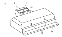
次に、非球面ミラー3を含む光学エンジン5と電気回路部9が収容される遮蔽筐体6について説明するが、最初に遮蔽筐体6の背面から視た構造について説明する。図4は、遮蔽筐体6の背面斜視図である。図4に示すように、遮蔽筐体6の背面部の上部には、支柱部材7に対して位置決めするための位置決めピン12が例えば2つ設けられている。上記のように遮蔽筐体6の背面部の下端部には、後方に突出する突出部6aが設けられている。遮蔽筐体6の前側上部には、非球面ミラー3で反射された映像光2が交差するエリアがあり、この部分に窓ガラス板52が取り付けられている。映像光2が交差するエリアに窓ガラス板52が配置されているので、窓ガラス板52のサイズは小さい。   Next, the shielding case 6 in which the optical engine 5 including the aspherical mirror 3 and the electric circuit unit 9 are accommodated will be described. First, the structure viewed from the back of the shielding case 6 will be described. FIG. 4 is a rear perspective view of the shielding housing 6. As shown in FIG. 4, for example, two positioning pins 12 for positioning with respect to the column member 7 are provided on the upper portion of the back surface portion of the shielding housing 6. As described above, the projecting portion 6 a projecting rearward is provided at the lower end portion of the back surface portion of the shielding housing 6. There is an area where the image light 2 reflected by the aspherical mirror 3 intersects at the upper front side of the shielding housing 6, and a window glass plate 52 is attached to this area. Since the window glass plate 52 is disposed in an area where the image light 2 intersects, the size of the window glass plate 52 is small.

次に、遮蔽筐体6内に収容される非球面ミラー3の保持構造について説明する。図5は、光学エンジン5の側面図であり、図6は、非球面ミラー3の保持構造の背面斜視図であり、図7は、非球面ミラー3の保持構造の斜視図である。図5に示すように、投射レンズ4の後部は本体部5aの前端に固定されるとともに、投射レンズ4の前部は投射レンズ保持部材39に固定されている。非球面ミラー3は、非球面ミラー保持部材38に固定され、非球面ミラー保持部材38は、投射レンズ保持部材39に固定されている。   Next, the holding structure of the aspherical mirror 3 accommodated in the shielding housing 6 will be described. FIG. 5 is a side view of the optical engine 5, FIG. 6 is a rear perspective view of the holding structure for the aspherical mirror 3, and FIG. 7 is a perspective view of the holding structure for the aspherical mirror 3. As shown in FIG. 5, the rear part of the projection lens 4 is fixed to the front end of the main body part 5 a, and the front part of the projection lens 4 is fixed to the projection lens holding member 39. The aspherical mirror 3 is fixed to an aspherical mirror holding member 38, and the aspherical mirror holding member 38 is fixed to a projection lens holding member 39.

図6と図7に示すように、非球面ミラー3の保持構造は、非球面ミラー3と、非球面ミラー保持部材38と、非球面ミラーピボット形状保持部38aと、バネ43,44,45と、調整部である非球面ミラー調整ネジ46,47と、バネ押付部材40,41,42とを備えている。   As shown in FIGS. 6 and 7, the holding structure of the aspherical mirror 3 includes an aspherical mirror 3, an aspherical mirror holding member 38, an aspherical mirror pivot holding part 38a, springs 43, 44, and 45. Aspherical mirror adjustment screws 46 and 47, which are adjustment parts, and spring pressing members 40, 41 and 42 are provided.

非球面ミラー3の前端部は、非球面ミラー保持部材38の非球面ミラーピボット形状保持部38aの先端面と当接するように配置され、非球面ミラー3の左右両端部は、非球面ミラー保持部材38に組み込まれた非球面ミラー調整ネジ46,47の先端面に配置され、非球面ミラー3の後端部は、非球面ミラーガイド形状保持部38bに挿入されている。非球面ミラー3における前端部および左右両端部は、バネ43,44,45を介して非球面ミラー保持部材38に固定されたバネ押付部材40,41,42によって、バネ押付部材40,41,42よりも後方への移動が規制されている。   The front end portion of the aspherical mirror 3 is disposed so as to come into contact with the front end surface of the aspherical mirror pivot shape holding portion 38a of the aspherical mirror holding member 38, and the left and right end portions of the aspherical mirror 3 are aspherical mirror holding members. The aspherical mirror adjustment screws 46 and 47 incorporated in the front end surface of the aspherical mirror 3 are disposed on the front end face of the aspherical mirror 3, and the rear end of the aspherical mirror 3 is inserted into the aspherical mirror guide shape holding part 38b. The front end portion and the left and right end portions of the aspherical mirror 3 are spring-pressing members 40, 41, 42 by spring-pressing members 40, 41, 42 fixed to the aspherical mirror holding member 38 via springs 43, 44, 45. The rearward movement is restricted.

なお、非球面ミラー保持部材38は、アルミ、マグネシウムなどのダイキャスト品、もしくは、樹脂などの成形品であってもよい。非球面ミラー3の調整部においては、非球面ミラーピボット形状保持部38aのピボット部を支点として、非球面ミラー調整ネジ46,47を時計回りまたは反時計回りに回すことで、非球面ミラー調整ネジ46,47の設置部が上下に移動し、非球面ミラー3が動くことで反射型スクリーン1上の映像歪みを調整することができる。特に光路の長い反射型スクリーン1の上側左右コーナー部での映像位置を補正することができる。   The aspherical mirror holding member 38 may be a die-cast product such as aluminum or magnesium, or a molded product such as resin. In the adjustment part of the aspherical mirror 3, the aspherical mirror adjustment screw 46, 47 is turned clockwise or counterclockwise with the pivot part of the aspherical mirror pivot shape holding part 38a as a fulcrum. The image distortion on the reflective screen 1 can be adjusted by moving the aspherical mirror 3 by moving the installation portions 46 and 47 up and down. In particular, the image position at the upper left and right corners of the reflective screen 1 having a long optical path can be corrected.

次に、図8と図9を用いて、非球面ミラー3の調整部である非球面ミラー調整ネジ46,47が遮蔽筐体6から露出する構造について説明する。図8は、遮蔽筐体6の前部に蓋部材48を取り付けた状態を示す斜視図であり、図9は、遮蔽筐体6から蓋部材48を取り外した状態を示す正面図である。図8と図9に示すように、遮蔽筐体6の前部には開口部6d,6eが形成され、開口部6d,6eを塞ぐように蓋部材48が取り付けられている。蓋部材48は、外部から簡単に取り外すことができる。図9に示すように、蓋部材48を取り外すことで開口部6d,6eが露出するため、外部から開口部6dを介して非球面ミラー調整ネジ46にアクセスすることができるとともに、開口部6eを介して非球面ミラー調整ネジ47にアクセスすることができ、非球面ミラー3の調整作業を行うことができる。   Next, a structure in which the aspherical mirror adjustment screws 46 and 47 that are adjustment parts of the aspherical mirror 3 are exposed from the shielding housing 6 will be described with reference to FIGS. 8 and 9. FIG. 8 is a perspective view showing a state in which the lid member 48 is attached to the front portion of the shielding housing 6, and FIG. 9 is a front view showing a state in which the lid member 48 is removed from the shielding housing 6. As shown in FIGS. 8 and 9, openings 6d and 6e are formed in the front portion of the shielding housing 6, and a lid member 48 is attached so as to close the openings 6d and 6e. The lid member 48 can be easily removed from the outside. As shown in FIG. 9, since the openings 6d and 6e are exposed by removing the lid member 48, the aspherical mirror adjusting screw 46 can be accessed from the outside via the opening 6d, and the opening 6e The aspherical mirror adjustment screw 47 can be accessed via the aspherical mirror 3 and the aspherical mirror 3 can be adjusted.

光学エンジン5を収容した遮蔽筐体6と反射型スクリーン1は、支柱部材7により、位置決めした状態で連結されているが、反射型スクリーン1が前後方向に倒れた場合、特に反射型スクリーン1の上部は感度が高いため、画面の位置が上下にばらつき、画面歪みが生じることがある。このように、感度の高い反射型スクリーン1の上部で画面歪みが生じた場合に、映像投射装置の外部から、非球面ミラー3の調整部にアクセスできるので、映像投射装置から遮蔽筐体6を分離することなく、反射型スクリーン1上の映像の画像歪みを調整することができ、最適な映像を得ることができる。   The shielding housing 6 housing the optical engine 5 and the reflective screen 1 are connected in a state of being positioned by a support member 7. However, when the reflective screen 1 is tilted in the front-rear direction, the reflective screen 1 is particularly arranged. Since the upper part has high sensitivity, the screen position may fluctuate vertically and screen distortion may occur. As described above, when screen distortion occurs in the upper part of the reflective screen 1 having high sensitivity, the adjustment unit of the aspherical mirror 3 can be accessed from the outside of the video projection device. The image distortion on the image on the reflective screen 1 can be adjusted without separation, and an optimum image can be obtained.

次に、反射型スクリーン1と遮蔽筐体6と支柱部材7との連結について説明する。図10は、映像投射装置の連結構造を示す背面斜視図である。図10に示すように、支柱部材7は、矩形状かつ板状に形成されている。支柱部材7には、位置決め用穴13および位置決め用穴14が形成され、位置決め用穴13には、スクリーン補強フレーム8d,8gの中央部に設けられた位置決めピン11が前側から挿入される。位置決め用穴14には、遮蔽筐体6の背面部に設けられた位置決めピン12が前側から挿入される。これにより、反射型スクリーン1と、光学エンジン5を収容する遮蔽筐体6との位置関係を決めることができる。   Next, the connection of the reflective screen 1, the shielding housing 6, and the support member 7 will be described. FIG. 10 is a rear perspective view showing the connection structure of the video projection apparatus. As shown in FIG. 10, the support | pillar member 7 is formed in rectangular shape and plate shape. A positioning hole 13 and a positioning hole 14 are formed in the column member 7, and a positioning pin 11 provided in the center of the screen reinforcing frames 8d and 8g is inserted into the positioning hole 13 from the front side. The positioning pins 12 provided on the back surface of the shielding housing 6 are inserted into the positioning holes 14 from the front side. Thereby, the positional relationship between the reflective screen 1 and the shielding housing 6 that houses the optical engine 5 can be determined.

それから、支柱部材7の内周部をスクリーン補強フレーム8および遮蔽筐体6の背面部にネジ固定することで、図2(a)と図2(b)に示す一体型の映像投射装置となる。支柱部材7を介して、反射型スクリーン1と、遮蔽筐体6内に収容・配置されている光学エンジン5の位置関係が決まるので、反射型スクリーン1上で、画面歪みの小さい・解像度感の良い最適な映像を得ることができる。支柱部材7を構成する部材としては、剛性が強く、平面度の良い金属板または押し出し材などが適している。   Then, by fixing the inner peripheral portion of the column member 7 to the screen reinforcing frame 8 and the back surface portion of the shielding housing 6, the integrated video projection device shown in FIGS. 2A and 2B is obtained. . Since the positional relationship between the reflective screen 1 and the optical engine 5 accommodated / arranged in the shielding housing 6 is determined via the support member 7, the screen distortion on the reflective screen 1 is small and the resolution is low. A good and optimal video can be obtained. As a member constituting the column member 7, a metal plate or an extruded material having high rigidity and good flatness is suitable.

以上のように、実施の形態1に係る映像投射装置では、遮蔽筐体6は、非球面ミラー3を含む光学エンジン5と電気回路部9とを収容するために必要なサイズでよいため、遮蔽筐体6の小型化が可能である。また、光学エンジン5が投射した映像光を反射するために、非球面ミラー3が使用されるため、反射型スクリーン1前面からの遮蔽筐体6の突出量は小さくなる。これにより、映像投射装置の薄型化、省スペース化を実現することができる。   As described above, in the video projection apparatus according to the first embodiment, the shielding housing 6 may be a size necessary to accommodate the optical engine 5 including the aspherical mirror 3 and the electric circuit unit 9. The housing 6 can be downsized. Further, since the aspherical mirror 3 is used to reflect the image light projected by the optical engine 5, the projection amount of the shielding housing 6 from the front surface of the reflective screen 1 is reduced. Thereby, thickness reduction and space saving of a video projector can be realized.

さらに、支柱部材7により遮蔽筐体6の背面部と反射型スクリーン1の背面部とが位置決めした状態で連結されるため、支柱部材7を介して、反射型スクリーン1と、遮蔽筐体6内に収容されている光学エンジン5との位置関係を正確に位置決めすることができる。これにより、反射型スクリーン1上で、画面歪みの小さい、解像度感の良い最適な映像を得ることができる。   Further, since the back surface portion of the shielding housing 6 and the back surface portion of the reflective screen 1 are connected to each other by the support column member 7, the reflective screen 1 and the inside of the shielding housing 6 are connected via the support member 7. It is possible to accurately position the positional relationship with the optical engine 5 housed therein. As a result, it is possible to obtain an optimal image with small screen distortion and good resolution on the reflective screen 1.

非球面ミラー3における反射型スクリーン1に対する映像光の反射角度を調整可能な非球面ミラー調整ネジ46,47をさらに備え、遮蔽筐体6の前部に、非球面ミラー調整ネジ46,47が露出する開口部6d,6eが形成されたため、映像投射装置から遮蔽筐体6を分離することなく、反射型スクリーン1上の映像の画像歪みを調整することができ、最適な映像を得ることができる。   Aspherical mirror adjustment screws 46 and 47 capable of adjusting the reflection angle of the image light with respect to the reflective screen 1 in the aspherical mirror 3 are further provided, and the aspherical mirror adjustment screws 46 and 47 are exposed at the front portion of the shielding housing 6. Since the openings 6d and 6e are formed, the image distortion of the image on the reflective screen 1 can be adjusted without separating the shielding housing 6 from the image projection device, and an optimum image can be obtained. .

なお、遮蔽筐体と支柱部材について図11に示す連結構造を採用してもよい。図11は、遮蔽筐体と支柱部材の連結構造の別の例である遮蔽筐体6Aと支柱部材7Aの連結構造を示す背面斜視図である。遮蔽筐体6Aの背面部の上部には、上方開放の窪み6bが形成されている。また、支柱部材7Aの下端部には、位置合わせ外形部7aが形成されている。位置合わせ外形部7aは窪み6bに嵌め込み可能に形成されている。   In addition, you may employ | adopt the connection structure shown in FIG. 11 about a shielding housing | casing and a support | pillar member. FIG. 11 is a rear perspective view showing a connection structure of the shielding housing 6A and the support member 7A, which is another example of the connection structure of the shielding housing and the support member. An upper open recess 6b is formed in the upper part of the back surface of the shielding housing 6A. Moreover, the alignment outer shape part 7a is formed in the lower end part of the support | pillar member 7A. The alignment outer shape portion 7a is formed so as to be fitted into the recess 6b.

支柱部材7Aを遮蔽筐体6Aに連結する際、支柱部材7Aの位置合わせ外形部7aを遮蔽筐体6Aの窪み6bに嵌め込むように取り付ける。それから、ネジで、背面側から支柱部材7Aを遮蔽筐体6Aに固定する。   When the support member 7A is connected to the shielding housing 6A, the alignment outer portion 7a of the support member 7A is attached so as to be fitted into the recess 6b of the shielding housing 6A. Then, the column member 7A is fixed to the shielding housing 6A from the back side with screws.

以上のように、遮蔽筐体6Aの背面部に上方開放の窪み6bが形成され、支柱部材7Aの下端部の位置合わせ外形部7aと窪み6bが位置決めされたため、支柱部材7Aと遮蔽筐体6Aの組み立て作業が容易である。   As described above, the recess 6b that is open upward is formed on the back surface of the shielding housing 6A, and the alignment outer portion 7a and the recess 6b at the lower end of the support member 7A are positioned. Assembling work is easy.

また、大画面スクリーンを搭載する映像投射装置の場合、映像を表示する大画面スクリーンをできるだけ壁に近い位置に設置したいという要求がある。図12に示すように、遮蔽筐体6Bの背面部の下部に、遮蔽筐体6Bに対して例えばネジなどで着脱可能に固定され、かつ、映像投射装置を自立可能に突出する突出部6a(第1突出部)を有する着脱可能部6cが設けられている。映像投射装置を壁にできるだけ近づけたいときに、着脱可能部6cを取り外し、支柱部材7の背面部が、壁面15に当接した状態で映像投射装置を設置することができる。反射型スクリーン1が壁に近いところに配置されるので、壁面15に反射型スクリーン1を掛けたイメージとなり、部屋内への突出量が減るので、映像投射装置においてさらなる省スペース化が可能である。   In addition, in the case of a video projection device equipped with a large screen, there is a demand for installing a large screen for displaying video as close to the wall as possible. As shown in FIG. 12, a protruding portion 6 a (which is fixed to the lower portion of the back surface of the shielding housing 6 B so as to be detachable with respect to the shielding housing 6 B with, for example, a screw and protrudes so that the image projection apparatus can stand on its own. A detachable portion 6c having a first projecting portion) is provided. When the video projection device is desired to be as close as possible to the wall, the removable portion 6c can be removed, and the video projection device can be installed in a state where the back surface portion of the column member 7 is in contact with the wall surface 15. Since the reflection type screen 1 is disposed near the wall, the image is obtained by hanging the reflection type screen 1 on the wall surface 15 and the amount of protrusion into the room is reduced. Therefore, further space saving can be achieved in the video projection apparatus. .

通常、映像投射装置を壁に掛けるためには、壁の工事または壁に壁掛け用の保持部材などを設置する必要があるが、本実施の形態の構成によれば、そのような手間を省くことができ、反射型スクリーン1を壁に近づけて配置することができる。着脱可能部6cは、図2(a)に示す突出部6aの機能すなわち映像投射装置が背面側に倒れないようにする機能を兼ねているが、映像投射装置を壁面15に近づけて設置する場合は、図12に示すように着脱可能部6cを取り外した後、支柱部材7を壁面15に当接させた状態で設置することで、映像投射装置が背面側に倒れないようにすることができる。   Usually, in order to hang the image projection apparatus on a wall, it is necessary to install a wall-holding member or the like on the wall or the wall, but according to the configuration of the present embodiment, such trouble is saved. The reflective screen 1 can be placed close to the wall. The detachable portion 6c also has the function of the protruding portion 6a shown in FIG. 2A, that is, the function of preventing the video projection device from falling to the back side, but the video projection device is installed close to the wall surface 15. As shown in FIG. 12, after the detachable part 6c is removed, the column member 7 is installed in a state where it abuts against the wall surface 15, so that the image projection device can be prevented from falling to the back side. .

以上のように、遮蔽筐体6Bから着脱可能に設けられ、かつ、遮蔽筐体6Bの背面部から自立可能に突出する突出部6aを有する着脱可能部6cをさらに備えたため、映像投射装置を壁に近づけて設置する際に、遮蔽筐体6Bから着脱可能部6cを取り外すことで、支柱部材7の背面部を壁面15に当接させた状態で、映像投射装置を設置することができる。また、支柱部材7の背面部が壁面15に当接しているため、映像投射装置を背面側に倒れないようにすることができる。   As described above, since the image projection apparatus is further provided with the detachable portion 6c that is provided so as to be detachable from the shielding housing 6B and has the protruding portion 6a that protrudes independently from the back surface of the shielding housing 6B. When installing close to the screen, the detachable portion 6c is removed from the shielding housing 6B, so that the video projection device can be installed in a state where the back surface portion of the column member 7 is in contact with the wall surface 15. Moreover, since the back surface part of the support | pillar member 7 is contact | abutting to the wall surface 15, it can prevent a video projector from falling down to the back side.

また、支柱部材7に透明部材を採用してもよい。図13は、支柱部材7に透明樹脂部材49,51と透明ガラス部材50を採用した場合の映像投射装置の連結構造を示す背面斜視図であり、図14は、映像投射装置の正面図であり、図15は、反射型スクリーン1上に投射された映像の浮遊イメージを説明する映像投射装置の正面図である。   Further, a transparent member may be adopted for the support member 7. FIG. 13 is a rear perspective view showing the connection structure of the video projection device when the transparent resin members 49 and 51 and the transparent glass member 50 are adopted for the support member 7, and FIG. 14 is a front view of the video projection device. FIG. 15 is a front view of a video projection apparatus for explaining a floating image of a video projected on the reflective screen 1.

図13に示すように、支柱部材7Bは、透明樹脂部材49と透明ガラス部材50と透明樹脂部材51の3層構造で構成されている。透明ガラス部材50は、3層構造の中心となる層に配置されており、反射型スクリーン1を支える強度メンバーとしての機能を有する。また、透明樹脂部材49,51は、透明ガラス部材50を両側から挟んで配置されており、透明ガラス部材50を保護している。このため、透明ガラス部材50が割れた場合でも、その破片が飛び散ることを抑制できる。ここで、透明樹脂部材49,51と透明ガラス部材50が透明部材に相当する。なお、透明ガラス部材50に飛散防止フィルムなどの表面防止処理がされていれば、透明ガラス部材50のみの一層構造でもよい。 As shown in FIG. 13, the column member 7 </ b> B has a three-layer structure including a transparent resin member 49, a transparent glass member 50, and a transparent resin member 51. The transparent glass member 50 is disposed in the layer that is the center of the three-layer structure, and has a function as a strength member that supports the reflective screen 1. The transparent resin members 49 and 51 are disposed with the transparent glass member 50 sandwiched from both sides, and protect the transparent glass member 50. For this reason, even when the transparent glass member 50 is broken, it is possible to suppress the fragments from scattering. Here, the transparent resin members 49 and 51 and the transparent glass member 50 correspond to transparent members . If the transparent glass member 50 is subjected to a surface prevention treatment such as a scattering prevention film, a single-layer structure of only the transparent glass member 50 may be used.

図14に示すように、反射型スクリーン1と遮蔽筐体6とを連結する支柱部材7Bとして、透明樹脂部材49,51および透明ガラス部材50が採用されている。支柱部材7Bが透明部材により形成されているため、図15に示すように、反射型スクリーン1が、遮蔽筐体6から分離された感覚となり、反射型スクリーン1上に投射された映像が浮遊したイメージを実現することができる。 As shown in FIG. 14, transparent resin members 49 and 51 and a transparent glass member 50 are employed as support members 7 </ b> B that connect the reflective screen 1 and the shielding housing 6. Since the support member 7B is formed of a transparent member , as shown in FIG. 15, the reflective screen 1 feels separated from the shielding housing 6, and the image projected on the reflective screen 1 floats. An image can be realized.

以上のように、支柱部材7Bは、透明樹脂部材49と透明ガラス部材50と透明樹脂部材51により形成されたため、反射型スクリーン1が遮蔽筐体6から分離された感覚となり、反射型スクリーン1上に投射された映像が浮遊したイメージを実現することができる。これにより、デザイン性の良い・斬新性のある映像投射装置が得られる。   As described above, since the column member 7B is formed of the transparent resin member 49, the transparent glass member 50, and the transparent resin member 51, it becomes a sense that the reflective screen 1 is separated from the shielding housing 6, and the It is possible to realize an image in which the projected image is floating. As a result, an image projection apparatus with good design and novelty can be obtained.

<実施の形態2>
次に、実施の形態2に係る映像投射装置について説明する。図16は、実施の形態2に係る映像投射装置のフレーム部材16の斜視図であり、図17は、フレーム部材16に補強部材22,23,24,25を取り付けた状態を示す斜視図であり、図18は、フレーム部材16と支柱部材7の連結構造を示す背面斜視図であり、図19は、フレーム部材16の背面部にカバーバック31を取り付けた状態を示す背面斜視図であり、図20は、反射型スクリーン1が支柱部材7に取り付けられて自立している状態を示す背面斜視図であり、図21は、遮蔽筐体6Cの下方から視た斜視図であり、図22は、反射型スクリーン1が固定された支柱部材7を支持するフレーム部材16と、遮蔽筐体6Cとの連結を説明する斜視図である。なお、実施の形態2において、実施の形態1で説明したものと同一の構成要素については同一符号を付して説明は省略する。
<Embodiment 2>
Next, a video projection apparatus according to Embodiment 2 will be described. FIG. 16 is a perspective view of the frame member 16 of the video projection apparatus according to the second embodiment, and FIG. 17 is a perspective view illustrating a state in which the reinforcing members 22, 23, 24, and 25 are attached to the frame member 16. 18 is a rear perspective view showing the connection structure of the frame member 16 and the column member 7, and FIG. 19 is a rear perspective view showing a state in which the cover back 31 is attached to the rear portion of the frame member 16. 20 is a rear perspective view showing a state in which the reflective screen 1 is attached to the column member 7 and is self-supporting, FIG. 21 is a perspective view seen from below the shielding housing 6C, and FIG. It is a perspective view explaining the connection with the frame member 16 which supports the support | pillar member 7 to which the reflective screen 1 was fixed, and the shielding housing | casing 6C. In the second embodiment, the same components as those described in the first embodiment are denoted by the same reference numerals, and the description thereof is omitted.

図16と図22に示すように、フレーム部材16は、支柱部材7と遮蔽筐体6Cとの間に着脱可能に連結される部材であり、フレーム本体部16aと、フレーム脚部17,18,19(第2突出部)とを備えている。フレーム本体部16aは矩形状に形成されるとともに、フレーム本体部16aの横幅は、支柱部材7の下端部を支持できるように支柱部材7の横幅よりも少し大きな寸法に形成されている。フレーム本体部16aの左右両端部と中央部における下端部には、脚部16b,16c,16dが形成されている。脚部16b,16c,16dの下端には、前方に突出するフレーム脚部17,18,19が固定されている。   As shown in FIGS. 16 and 22, the frame member 16 is a member that is detachably connected between the column member 7 and the shielding housing 6C, and includes a frame main body portion 16a, frame leg portions 17, 18, and 19 (second projecting portion). The frame body 16a is formed in a rectangular shape, and the width of the frame body 16a is slightly larger than the width of the column member 7 so that the lower end of the column member 7 can be supported. Legs 16b, 16c, and 16d are formed at the left and right ends of the frame main body 16a and the lower end at the center. Frame leg portions 17, 18 and 19 projecting forward are fixed to lower ends of the leg portions 16b, 16c and 16d.

また、フレーム本体部16aの前面の左右両端部寄りには、位置決めピン20,21が取り付けられている。図17に示すように、フレーム本体部16aの前面には補強部材22が固定され、脚部16b,16c,16dの前面には補強部材23,24,25が固定されている。補強部材22により、フレーム本体部16aの剛性が向上し、補強部材23,24,25により、フレーム本体部16aとフレーム脚部17,18,19との角度が安定した状態となる。ここで、補強部材22においてフレーム本体部16aの位置決めピン20,21に対応する位置に穴(図示省略)が形成されており、これらの穴から位置決めピン20,21が突出している。   In addition, positioning pins 20 and 21 are attached near the left and right ends of the front surface of the frame main body 16a. As shown in FIG. 17, the reinforcing member 22 is fixed to the front surface of the frame main body portion 16a, and the reinforcing members 23, 24, and 25 are fixed to the front surfaces of the leg portions 16b, 16c, and 16d. The reinforcement member 22 improves the rigidity of the frame body 16a, and the reinforcement members 23, 24, and 25 stabilize the angle between the frame body 16a and the frame legs 17, 18, and 19. Here, holes (not shown) are formed in the reinforcing member 22 at positions corresponding to the positioning pins 20 and 21 of the frame main body 16a, and the positioning pins 20 and 21 protrude from these holes.

図18に示すように、脚部16b,16c,16dの背面部には補強部材28,27,26が固定されている。補強部材26,27,28により、フレーム本体部16aとフレーム脚部17,18,19との角度が安定した状態となる。支柱部材7の位置決め用穴14が、フレーム本体部16aの位置決めピン29,30に背面側から挿入されることにより、支柱部材7とフレーム部材16の位置関係が決まる。それから、支柱部材7が背面側からネジでフレーム部材16に固定される。   As shown in FIG. 18, the reinforcing members 28, 27, and 26 are fixed to the back surfaces of the leg portions 16b, 16c, and 16d. By the reinforcing members 26, 27, and 28, the angle between the frame main body portion 16a and the frame leg portions 17, 18, and 19 is stabilized. The positioning hole 14 of the column member 7 is inserted into the positioning pins 29 and 30 of the frame main body 16a from the back side, whereby the positional relationship between the column member 7 and the frame member 16 is determined. Then, the support member 7 is fixed to the frame member 16 with screws from the back side.

図19に示すように、フレーム部材16の背面部には、フレーム部材16の背面側を覆うカバー部材であるカバーバック31が固定されている。より具体的には、フレーム本体部16a、補強部材26,27,28およびフレーム脚部17,18,19を背面側から覆い隠すように、フレーム部材16の背面部にカバーバック31が固定されている。また、カバーバック31の下端部には、映像投射装置を自立可能に後方に突出する突出部31aが形成されている。カバーバック31によりフレーム部材16の背面側を覆うことができるため、フレーム部材16および補強部材26,27,28に使用者の手が直接触れることがなくなり安全性が高まる。   As shown in FIG. 19, a cover back 31, which is a cover member that covers the back side of the frame member 16, is fixed to the back surface of the frame member 16. More specifically, the cover back 31 is fixed to the back surface portion of the frame member 16 so as to cover the frame main body portion 16a, the reinforcing members 26, 27, and 28 and the frame leg portions 17, 18, and 19 from the back surface side. Yes. In addition, a protrusion 31 a is formed at the lower end of the cover back 31 so as to protrude rearward so that the video projection device can stand on its own. Since the back side of the frame member 16 can be covered with the cover back 31, the user's hand does not directly touch the frame member 16 and the reinforcing members 26, 27, and 28, thereby improving safety.

図20に示すように、フレーム脚部17,18,19により、反射型スクリーン1が前側に倒れることを防止している。突出部31aにより、反射型スクリーン1が後側に倒れることを防止している。したがって、支柱部材7に反射型スクリーン1が固定された状態、すなわち、遮蔽筐体6Cが取り付けられていない状態(または遮蔽筐体6Cが取り外された状態)でも、支柱部材7に固定されたフレーム部材16のフレーム脚部17,18,19とカバーバック31の突出部31aにより、反射型スクリーン1は自立することができる。   As shown in FIG. 20, the frame legs 17, 18, 19 prevent the reflective screen 1 from falling forward. The protrusion 31a prevents the reflective screen 1 from falling to the rear side. Therefore, the frame fixed to the column member 7 even when the reflective screen 1 is fixed to the column member 7, that is, when the shield case 6C is not attached (or when the shield case 6C is removed). The reflective screen 1 can stand on its own by the frame leg portions 17, 18, 19 of the member 16 and the protruding portion 31 a of the cover back 31.

図21に示すように、遮蔽筐体6Cの左右両端部と中央部における底面部には、前後方向に延びるガイド部33,34,35が形成されている。遮蔽筐体6Cの背面部は平面状に形成され、実施の形態1で説明した突出部は設けられていない。また、遮蔽筐体6Cの背面部には位置決め用穴36、37が形成されている。   As shown in FIG. 21, guide portions 33, 34, and 35 extending in the front-rear direction are formed on the left and right ends of the shielding housing 6 </ b> C and the bottom surface at the center. The back surface of the shielding housing 6C is formed in a planar shape, and the protrusion described in the first embodiment is not provided. In addition, positioning holes 36 and 37 are formed on the back surface of the shielding housing 6C.

図22に示すように、前側から遮蔽筐体6Cをスライドすることにより、遮蔽筐体6Cの底面部に設けられたガイド部33,34,35が、それぞれ、フレーム脚部17,18,19へ嵌り込み、遮蔽筐体6Cの背面部が、補強部材22の前面に当接する。このとき、フレーム部材16の位置決めピン20,21が遮蔽筐体6Cの背面部に設けられた位置決め用穴36,37に挿入され、フレーム部材16と遮蔽筐体6Cとが位置決めされる。この後、カバーバック31側から、遮蔽筐体6Cに対してネジ固定される。   As shown in FIG. 22, by sliding the shielding housing 6C from the front side, the guide portions 33, 34, and 35 provided on the bottom surface of the shielding housing 6C are moved to the frame leg portions 17, 18, and 19, respectively. The rear surface portion of the shielding housing 6 </ b> C comes into contact with the front surface of the reinforcing member 22. At this time, the positioning pins 20 and 21 of the frame member 16 are inserted into the positioning holes 36 and 37 provided on the back surface of the shielding housing 6C, and the frame member 16 and the shielding housing 6C are positioned. Thereafter, screws are fixed to the shielding housing 6C from the cover back 31 side.

その結果、光学エンジン5を収容した遮蔽筐体6Cと支柱部材7は、フレーム部材16により位置決めされ、また、支柱部材7は、反射型スクリーン1の背面部に配置されたスクリーン補強フレーム8により位置決めされるので、遮蔽筐体6Cの内部に配置された光学エンジン5と、反射型スクリーン1の位置関係が決まる。これにより、反射型スクリーン1上で、画面歪みの小さい・解像度感の良い最適な映像を得ることができる。   As a result, the shielding housing 6C housing the optical engine 5 and the column member 7 are positioned by the frame member 16, and the column member 7 is positioned by the screen reinforcing frame 8 disposed on the back surface of the reflective screen 1. Therefore, the positional relationship between the optical engine 5 disposed inside the shielding housing 6C and the reflective screen 1 is determined. As a result, it is possible to obtain an optimal image with a small screen distortion and a good resolution on the reflective screen 1.

映像投射装置を移動・運搬する際には、映像投射装置から遮蔽筐体6Cを取り外し、支柱部材7およびフレーム部材16により支持された反射型スクリーン1と、遮蔽筐体6Cとに分離した状態で、それぞれを持ち運ぶことができる。図20に示すように、反射型スクリーン1は自立することができるので、設置性も良い。仮に、遮蔽筐体6C内の電気回路部9および光学エンジン5が故障した場合でも、映像投射装置から遮蔽筐体6Cを分離して、遮蔽筐体6C内のみを修理・メンテナンスすることができる。   When moving and transporting the video projection device, the shielding housing 6C is removed from the video projection device, and the screen is separated into the reflective screen 1 supported by the column member 7 and the frame member 16 and the shielding housing 6C. , You can carry each one. As shown in FIG. 20, since the reflective screen 1 can stand on its own, the installation property is also good. Even if the electric circuit unit 9 and the optical engine 5 in the shielding housing 6C break down, the shielding housing 6C can be separated from the video projection device, and only the inside of the shielding housing 6C can be repaired and maintained.

以上のように、実施の形態2に係る映像投射装置では、支柱部材7と遮蔽筐体6Cとの間に着脱可能に連結され、かつ、遮蔽筐体6Cが取り外された状態で反射型スクリーン1を自立可能に突出するフレーム脚部17,18,19を有するフレーム部材16をさらに備えたため、支柱部材7に固定された反射型スクリーン1は、フレーム部材16のフレーム脚部17,18,19により、遮蔽筐体6Cを分離した状態でも自立することができ、設置性も良い。このため、仮に、遮蔽筐体6C内の電気回路部9および光学エンジン5が故障した場合でも、映像投射装置から遮蔽筐体6Cを分離して、遮蔽筐体6C内のみを修理・メンテナンスすることができる。   As described above, in the video projection device according to Embodiment 2, the reflective screen 1 is detachably connected between the support member 7 and the shielding housing 6C and the shielding housing 6C is removed. Since the frame member 16 having the frame leg portions 17, 18, and 19 projecting in a self-supporting manner is further provided, the reflective screen 1 fixed to the column member 7 is supported by the frame leg portions 17, 18, 19 of the frame member 16 In addition, it can stand on its own in a state where the shielding housing 6C is separated, and is easy to install. For this reason, even if the electrical circuit unit 9 and the optical engine 5 in the shielding housing 6C break down, the shielding housing 6C is separated from the video projection device, and only the inside of the shielding housing 6C is repaired and maintained. Can do.

遮蔽筐体6Cの底面部にガイド部33,34,35を設け、フレーム脚部17,18,19はガイド部33,34,35にスライド挿入可能に形成されたため、遮蔽筐体6Cとフレーム部材16とを容易に位置決めした状態で連結することができる。   Since the guide portions 33, 34, and 35 are provided on the bottom surface of the shielding housing 6C and the frame leg portions 17, 18, and 19 are formed so as to be slidable into the guide portions 33, 34, and 35, the shielding housing 6C and the frame member are provided. 16 can be connected in an easily positioned state.

大画面スクリーンを搭載する映像投射装置の場合、映像を表示する大画面スクリーンをできるだけ壁に近い位置に設置したいという要求がある。図23に示すように、カバーバック31Aの背面部に、カバーバック31Aの背面部の下端部から後方に突出し、かつ、カバーバック31Aに対して例えばネジなどで着脱可能に固定された第3突出部である着脱可能部32が設けられている。映像投射装置を壁にできるだけ近づけたいときに、着脱可能部32を取り外し、カバーバック31Aの背面部が壁面15に当接するように、映像投射装置を設置することができる。 In the case of a video projection device equipped with a large screen, there is a demand to install a large screen for displaying video as close to the wall as possible. As shown in FIG. 23 , a third protrusion that protrudes rearward from the lower end of the back surface of the cover back 31A and is detachably fixed to the cover back 31A with a screw or the like, for example, on the back surface of the cover back 31A. The detachable part 32 which is a part is provided. When it is desired to bring the video projection device as close as possible to the wall, the video projection device can be installed such that the detachable portion 32 is removed and the back portion of the cover back 31A is in contact with the wall surface 15.

反射型スクリーン1が壁に近い位置に配置されるので、壁面15に反射型スクリーン1を掛けたイメージとなり、部屋内への突出量が減るので、さらなる省スペース化が可能である。通常、映像投射装置の壁掛けには、壁の工事または壁に壁掛け用の保持部材などを設置する必要があるが、本発明の構成によれば、そのような手間を省くことができ、反射型スクリーン1を壁に近づけて配置することができる。   Since the reflective screen 1 is disposed at a position close to the wall, the image is obtained by placing the reflective screen 1 on the wall surface 15 and the amount of protrusion into the room is reduced, so that further space saving can be achieved. Usually, it is necessary to install a wall-hanging holding member or the like on the wall for the wall hanging of the image projection apparatus, but according to the configuration of the present invention, such trouble can be saved, and the reflection type The screen 1 can be placed close to the wall.

着脱可能部32は、図20で示す突出部31aの機能すなわち映像投射装置が背面側に倒れないようにする機能を兼ねているが、図23に示すように着脱可能部32を取り外して、壁面15に近づけて設置する場合は、支柱部材7が壁面15に接近し、カバーバック31Aの背面が壁面15に当接されるので、映像投射装置が背面側に倒れないようにすることができる。   The detachable portion 32 also has the function of the projecting portion 31a shown in FIG. 20, that is, the function of preventing the video projection device from falling to the back side, but the detachable portion 32 is removed as shown in FIG. In the case of installation close to 15, the column member 7 approaches the wall surface 15, and the back surface of the cover back 31 </ b> A comes into contact with the wall surface 15, so that the image projection device can be prevented from falling to the back side.

以上のように、フレーム部材16の背面側を覆うカバーバック31Aと、カバーバック31Aの背面部に自立可能に突出し、かつ、カバーバック31Aから着脱可能な着脱可能部32とをさらに備えたため、映像投射装置を壁に近づけて設置する際に、カバーバック31Aから着脱可能部32を取り外すことで、支柱部材7の背面部を壁面15に接近させるとともに、カバーバック31Aの背面部を壁面15に当接させた状態で、映像投射装置を設置することができる。また、カバーバック31Aの背面部が壁面15に当接しているため、映像投射装置を背面側に倒れないようにすることができる。   As described above, since the cover back 31A that covers the back side of the frame member 16 and the detachable portion 32 that protrudes on the back side of the cover back 31A and is detachable from the cover back 31A are further provided. When installing the projection device close to the wall, the removable portion 32 is removed from the cover back 31A, so that the back surface portion of the column member 7 approaches the wall surface 15 and the back surface portion of the cover back 31A is applied to the wall surface 15. The image projection device can be installed in a state of contact. Further, since the back surface portion of the cover back 31A is in contact with the wall surface 15, the video projection device can be prevented from falling to the back side.

なお、本発明は、その発明の範囲内において、各実施の形態を自由に組み合わせたり、各実施の形態を適宜、変形、省略することが可能である。   It should be noted that the present invention can be freely combined with each other within the scope of the invention, and each embodiment can be appropriately modified or omitted.

1 反射型スクリーン、3 非球面ミラー、5 光学エンジン、6,6A,6B,6C 遮蔽筐体、6a 突出部、6b 窪み、6c 着脱可能部、6d,6e 開口部、7,7A,7B 支柱部材、9 電気回路部、16 フレーム部材、17,18,19 フレーム脚部、31,31A カバーバック、32 着脱可能部、33,34,35 ガイド部、46,47 非球面ミラー調整ネジ、49,51 透明樹脂部材、50 透明ガラス部材。   DESCRIPTION OF SYMBOLS 1 Reflective type screen, 3 Aspherical mirror, 5 Optical engine, 6, 6A, 6B, 6C Shielding housing, 6a Protruding part, 6b Depression, 6c Detachable part, 6d, 6e Opening part, 7, 7A, 7B Prop member , 9 Electrical circuit part, 16 Frame member, 17, 18, 19 Frame leg part, 31, 31A Cover back, 32 Detachable part, 33, 34, 35 Guide part, 46, 47 Aspherical mirror adjustment screw, 49, 51 Transparent resin member, 50 transparent glass member.

Claims (5)

映像光を投射する光学エンジンと、
前記光学エンジンが投射した前記映像光を光軸を中心とした回転対称形状の反射面で反射する反射光学素子と、
前記反射光学素子が反射した前記映像光を映し出す反射型スクリーンと、
前記光学エンジンと、前記反射光学素子と、前記光学エンジンを電気的に駆動する電気回路部とを収容する遮蔽筐体と、
自立可能に突出する第2突出部を有するフレーム部材と、
前記フレーム部材の背面部と、前記反射型スクリーンの背面部とを位置決めした状態で連結する支柱部材と、
を備え、
前記遮蔽筐体は、自身の背面部と、前記反射型スクリーンの背面部とを位置決めした状態で、前記フレーム部材の前記第2突出部に着脱可能に連結され、かつ、自身が取り付けられた状態で前記反射型スクリーンを自立させ、
前記フレーム部材は、前記遮蔽筐体が取り外された状態で前記第2突出部により前記反射型スクリーンを自立させる、映像投射装置。
An optical engine that projects image light;
A reflective optical element that reflects the image light projected by the optical engine with a reflection surface having a rotationally symmetric shape about the optical axis;
A reflective screen for projecting the image light reflected by the reflective optical element;
A shielding housing that houses the optical engine, the reflective optical element, and an electric circuit unit that electrically drives the optical engine;
A frame member having a second protrusion that protrudes in a self-supporting manner;
A column member that connects the back surface of the frame member and the back surface of the reflective screen in a positioned state;
With
The shielding housing is detachably connected to the second projecting portion of the frame member in a state where the back surface portion of the shielding housing and the back surface portion of the reflective screen are positioned, and the shielding housing is attached thereto. To make the reflective screen self-supporting,
The frame projection device , wherein the frame member causes the reflective screen to stand on its own by the second projecting portion in a state where the shielding housing is removed .
前記遮蔽筐体の底面部にガイド部を設け、前記第2突出部は前記ガイド部にスライド挿入可能に形成された、請求項記載の映像投射装置。 It said shield the guide portion provided on the bottom surface of the housing, wherein the second protrusion is slid insertably formed on the guide portion, the video projection apparatus according to claim 1. 前記フレーム部材の背面側を覆うカバー部材と、
前記カバー部材の背面部に自立可能に突出し、かつ、前記カバー部材から着脱可能な第3突出部とをさらに備えた、請求項または請求項記載の映像投射装置。
A cover member covering the back side of the frame member;
Free-standing protrude to the rear portion of the cover member, and wherein further comprising a third projecting portion detachable from the cover member, the image projection apparatus according to claim 1 or claim 2, wherein.
前記反射光学素子における前記反射型スクリーンに対する前記映像光の反射角度を調整可能な調整部をさらに備え
前記遮蔽筐体の前部に、前記調整部が露出する開口部が形成された、請求項1〜のいずれか1つに記載の映像投射装置。
The adjustment part which can adjust the reflection angle of the said image light with respect to the said reflection type screen in the said reflection optical element is further provided, The opening part which the said adjustment part exposes was formed in the front part of the said shielding housing | casing. The video projection device according to any one of to 3 .
前記支柱部材は透明部材により形成された、請求項1〜のいずれか1つに記載の映像投射装置。 The strut member is formed by a transparent member, the image projection apparatus according to any one of claims 1-4.
JP2012249085A 2012-11-13 2012-11-13 Video projection device Expired - Fee Related JP6091171B2 (en)

Priority Applications (2)

Application Number Priority Date Filing Date Title
JP2012249085A JP6091171B2 (en) 2012-11-13 2012-11-13 Video projection device
US14/023,097 US9547221B2 (en) 2012-11-13 2013-09-10 Video projection device

Applications Claiming Priority (1)

Application Number Priority Date Filing Date Title
JP2012249085A JP6091171B2 (en) 2012-11-13 2012-11-13 Video projection device

Publications (3)

Publication Number Publication Date
JP2014098738A JP2014098738A (en) 2014-05-29
JP2014098738A5 JP2014098738A5 (en) 2015-11-05
JP6091171B2 true JP6091171B2 (en) 2017-03-08

Family

ID=50681382

Family Applications (1)

Application Number Title Priority Date Filing Date
JP2012249085A Expired - Fee Related JP6091171B2 (en) 2012-11-13 2012-11-13 Video projection device

Country Status (2)

Country Link
US (1) US9547221B2 (en)
JP (1) JP6091171B2 (en)

Families Citing this family (5)

* Cited by examiner, † Cited by third party
Publication number Priority date Publication date Assignee Title
JP6684538B2 (en) * 2014-09-30 2020-04-22 株式会社ジーグ Performance unit
JP6471570B2 (en) * 2015-03-25 2019-02-20 セイコーエプソン株式会社 Projection optical device and projector
US20170115552A1 (en) * 2015-10-23 2017-04-27 Jason Ward Image Projection System
KR102310718B1 (en) * 2017-03-20 2021-10-08 삼성전자주식회사 Convertible stand of display apparatus
JP2022036752A (en) * 2020-08-24 2022-03-08 リコーインダストリアルソリューションズ株式会社 Lens unit and image projection device

Family Cites Families (19)

* Cited by examiner, † Cited by third party
Publication number Priority date Publication date Assignee Title
JPS593664Y2 (en) * 1978-09-20 1984-02-01 ソニー株式会社 Mirror opening/closing device in video projector
JPH05336479A (en) * 1992-06-04 1993-12-17 Mitsubishi Electric Corp Reflective front projector
US5580146A (en) * 1992-11-20 1996-12-03 Projectavision, Inc. Rear screen video display system
US5491585A (en) 1992-11-20 1996-02-13 Projectavision, Inc. Portable rear screen television cabinet
JP3440611B2 (en) * 1994-03-16 2003-08-25 セイコーエプソン株式会社 Portable screen
JPH0888821A (en) * 1994-05-17 1996-04-02 Projectavision Inc Rear screen video display system with exposure beam passage
JPH10319501A (en) 1997-05-21 1998-12-04 Canon Inc Rear projection monitor
JP2002082387A (en) * 2000-06-28 2002-03-22 Victor Co Of Japan Ltd Projection display device
JP2002311506A (en) * 2001-04-13 2002-10-23 Os:Kk Folding screen
JP2005292210A (en) * 2004-03-31 2005-10-20 Canon Inc Electronic apparatus enclosure structure and projector device
JP4279315B2 (en) * 2005-09-21 2009-06-17 三菱電機株式会社 Projection device and cabinet thereof
US20070171383A1 (en) * 2006-01-23 2007-07-26 Brown International Corporation Portable battlewall display stand
JP5140969B2 (en) * 2006-09-07 2013-02-13 セイコーエプソン株式会社 projector
US8040602B1 (en) * 2007-09-07 2011-10-18 Sima Technologies Llc Frame assembly for a projection screen system
JP5091726B2 (en) 2008-03-10 2012-12-05 株式会社日立製作所 Projection display system
JP4730434B2 (en) * 2008-12-25 2011-07-20 日本ビクター株式会社 Screen assembly and rear projection type image display device
DE102009005273A1 (en) * 2009-01-20 2010-07-22 Mitja Jelusic Rear projection system, manufacturing process and application
US8919966B2 (en) * 2009-01-29 2014-12-30 Speranza, Inc. Rotatable mounting system for a projection system
JP5473644B2 (en) * 2010-02-04 2014-04-16 三菱電機株式会社 Video projection device

Also Published As

Publication number Publication date
US9547221B2 (en) 2017-01-17
US20140132847A1 (en) 2014-05-15
JP2014098738A (en) 2014-05-29

Similar Documents

Publication Publication Date Title
JP5381375B2 (en) Projector ceiling hanger
JP6091171B2 (en) Video projection device
JP4901648B2 (en) Stand for projection display
US8096663B2 (en) Projection display device and stand used for the projection display device
JP4428434B2 (en) Optical device and projector
JP2011095352A5 (en)
JP5988605B2 (en) Video projection device
TWI547748B (en) Electronic device with internal camera
JP6524672B2 (en) projector
US20110279791A1 (en) Projector
JP2008076861A (en) Projector
JP2010181456A (en) Projector
JP2006126436A (en) Rear projection type imaging apparatus
JP2010091645A (en) Adjusting mechanism and projector
JPWO2019159637A1 (en) Head-up display device
JP2007155915A (en) Projection lens unit
JP6463015B2 (en) Optical device and projection display device using the same
JP5136312B2 (en) Projection unit and electronic device
JP3050201B2 (en) Projection display device
JP6617639B2 (en) projector
JP4423997B2 (en) projector
JP2004272093A (en) Projector
JP2021128330A (en) Projection device and operation detection device
WO2010067688A1 (en) Projection device
JP2004272091A (en) Projector

Legal Events

Date Code Title Description
A521 Request for written amendment filed

Free format text: JAPANESE INTERMEDIATE CODE: A523

Effective date: 20150911

A621 Written request for application examination

Free format text: JAPANESE INTERMEDIATE CODE: A621

Effective date: 20150911

A977 Report on retrieval

Free format text: JAPANESE INTERMEDIATE CODE: A971007

Effective date: 20160722

A131 Notification of reasons for refusal

Free format text: JAPANESE INTERMEDIATE CODE: A131

Effective date: 20160726

A521 Request for written amendment filed

Free format text: JAPANESE INTERMEDIATE CODE: A523

Effective date: 20160923

TRDD Decision of grant or rejection written
A01 Written decision to grant a patent or to grant a registration (utility model)

Free format text: JAPANESE INTERMEDIATE CODE: A01

Effective date: 20170110

A61 First payment of annual fees (during grant procedure)

Free format text: JAPANESE INTERMEDIATE CODE: A61

Effective date: 20170207

R150 Certificate of patent or registration of utility model

Ref document number: 6091171

Country of ref document: JP

Free format text: JAPANESE INTERMEDIATE CODE: R150

R250 Receipt of annual fees

Free format text: JAPANESE INTERMEDIATE CODE: R250

R250 Receipt of annual fees

Free format text: JAPANESE INTERMEDIATE CODE: R250

LAPS Cancellation because of no payment of annual fees