JP2005292210A - Electronic apparatus enclosure structure and projector device - Google Patents
Electronic apparatus enclosure structure and projector device Download PDFInfo
- Publication number
- JP2005292210A JP2005292210A JP2004103214A JP2004103214A JP2005292210A JP 2005292210 A JP2005292210 A JP 2005292210A JP 2004103214 A JP2004103214 A JP 2004103214A JP 2004103214 A JP2004103214 A JP 2004103214A JP 2005292210 A JP2005292210 A JP 2005292210A
- Authority
- JP
- Japan
- Prior art keywords
- housing
- exhaust
- wall
- terminal
- casing
- Prior art date
- Legal status (The legal status is an assumption and is not a legal conclusion. Google has not performed a legal analysis and makes no representation as to the accuracy of the status listed.)
- Pending
Links
Images


Landscapes
- Cooling Or The Like Of Electrical Apparatus (AREA)
- Projection Apparatus (AREA)
- Insertion, Bundling And Securing Of Wires For Electric Apparatuses (AREA)
- Transforming Electric Information Into Light Information (AREA)
Abstract
Description
本発明は、転倒防止金具等を備えた薄型の筐体を有し、壁にぴったりとつけて設置することのできる据置型の電子機器筐体構造およびプロジェクタ装置に関するものである。 The present invention relates to a stationary electronic device casing structure and a projector apparatus that have a thin casing having a fall-preventing metal fitting and the like, and can be installed in close contact with a wall.
照明用の光源等を内蔵するプロジェクタ装置等の電子機器の筐体の背面には、筐体内部の電子部品を冷却するための排気口が設けられる。例えば、特許文献1に開示されたプロジェクタ装置(背面投写型画像表示装置)においては、図12に示すように、壁面Wに当接されるバックカバー104に段差部104aを設けて、下部の排気口105が壁面Wによって塞がれることのないように工夫されている。この装置の内部には、光像を出射する投写管101、その光像を反射させる反射鏡102が内蔵され、前面側には、光像が投射されるスクリーン103が配置されている。そして、筐体底部の吸気口106、バックカバー104の排気口105によって換気が図られ、装置内部の各種光学部品、電装部、液晶ライトバルブ等の昇温を防ぐように構成されていた。
An exhaust port for cooling the electronic components inside the housing is provided on the back surface of the housing of an electronic device such as a projector apparatus incorporating a light source for illumination. For example, in the projector device (rear projection type image display device) disclosed in
バックカバー104には段差部104aを設けてあるため、前述のように、プロジェクタ装置を壁面Wにぴったりとつけて設置しても、壁面Wが排気口105を塞ぐことはない。
従来のプロジェクタ装置等電子機器の筐体構造においては、筐体内の冷却を筐体の背面に設けた排気口によって行っており、特許文献1に開示されたように、装置を壁にぴったりとつけて設置可能にするために、筐体上部の奥行き寸法を筐体下部よりも大きく構成し、筐体下部の背面に排気口を設けて、筐体を壁にぴったりとつけた場合に排気口が壁面によって塞がれることを防止しているが、プロジェクタ装置等の薄型化が進む中で、筐体に段差部がない構成にすると、排気口が壁面に塞がれるため、壁から離して設置しなければならない。このような設置方法では、装置を薄型化した意味がなくなる。
In the case structure of a conventional electronic device such as a projector device, the inside of the case is cooled by an exhaust port provided on the back of the case. As disclosed in
本発明は上記従来の技術の有する未解決の課題に鑑みてなされたものであり、据置型のプロジェクタ装置等の電子機器の背面を壁面に密着させて設置したときに、換気のための排気方向等を自動的に切換えることのできる電子機器筐体構造およびプロジェクタ装置を提供することを目的とするものである。 The present invention has been made in view of the above-mentioned unsolved problems of the prior art, and the exhaust direction for ventilation when the back surface of an electronic device such as a stationary projector device is installed in close contact with the wall surface. It is an object of the present invention to provide an electronic device casing structure and a projector device that can automatically switch the above.
上記目的を達成するため、本発明の電子機器筐体構造は、電子部品を内蔵し、構築物の壁面に密着自在である背面を有する筐体と、前記筐体の前記背面に開口する第1の排気口と、前記筐体の一側面に開口する第2の排気口と、前記筐体と前記壁面間のスペースを検出する検出手段と、前記検出手段の出力に基づいて前記第1および前記第2の排気口を交互に閉鎖することで、前記筐体の換気のための排気方向の切換を行うシャッター手段とを有することを特徴とする。 In order to achieve the above object, an electronic device casing structure of the present invention includes a casing having a back surface that incorporates electronic components and is in close contact with a wall surface of a structure, and a first opening that opens on the back surface of the casing. An exhaust port; a second exhaust port that opens on one side of the housing; a detection unit that detects a space between the housing and the wall surface; and the first and the second based on an output of the detection unit And shutter means for switching the exhaust direction for ventilation of the casing by alternately closing the two exhaust ports.
本発明のプロジェクタ装置は、前面のスクリーンに光像を投写する投写管を内蔵し、構築物の壁面に密着自在である背面を有する筐体と、前記筐体の前記背面に開口する第1の排気口と、前記筐体の一側面に開口する第2の排気口と、前記筐体と前記壁面間のスペースを検出する検出手段と、前記検出手段の出力に基づいて前記第1および前記第2の排気口を交互に閉鎖することで、前記筐体の換気のための排気方向の切換を行うシャッター手段とを有することを特徴とする。 The projector device according to the present invention includes a housing having a projection tube for projecting a light image on a front screen and having a back surface that is in close contact with a wall surface of a structure, and a first exhaust opening at the back surface of the housing. An opening, a second exhaust opening opened on one side of the housing, a detecting means for detecting a space between the housing and the wall surface, and the first and second based on the output of the detecting means And shutter means for switching the exhaust direction for ventilation of the casing by alternately closing the exhaust ports.
壁とプロジェクタ装置等の筐体の背面との間のスペースを検知する検知手段を備え、検知手段の出力により自動的に排気方向を切換える構成であるため、プロジェクタ装置等を構築物である室内の壁にぴったりとつけて設置することができる。その結果、装置と壁との間に排気のための無駄なスペースを確保する必要がなく、スペースの有効利用を図ることができる。 Since it is configured to detect the space between the wall and the back surface of the housing of the projector device or the like, and the exhaust direction is automatically switched by the output of the detection device, the projector device or the like is an indoor wall that is a structure. It can be installed with a perfect fit. As a result, it is not necessary to secure a useless space for exhaust between the apparatus and the wall, and the space can be effectively used.
また、検知手段により入出力端子の接続方向を自動的に切換える構成にすることで、1個の入出力端子を筐体の背面側と側面側との双方で使用することが可能となる。 Further, by adopting a configuration in which the connection direction of the input / output terminals is automatically switched by the detection means, it is possible to use one input / output terminal on both the back side and the side surface side of the housing.
さらに、筐体下部の幅寸法を、少なくとも一部分がスクリーンを有する筐体上部の画像表示部の幅寸法より小さくなるように設定し、筐体下部で側面排気を行うように構成することで、プロジェクタ装置の隣に他の物、例えば、本棚を配置したり、複数のプロジェクタ装置を隣接して配置することが可能となる。すなわちプロジェクタ装置の側方に、側面排気のためのスペースを設ける必要がなく、他の物を密着して配置することで、スペースの有効利用をより一層促進できる。 Further, the projector is configured such that the width dimension of the lower part of the casing is set to be smaller than the width dimension of the image display unit in the upper part of the casing having a screen, and the side exhaust is performed at the lower part of the casing. It is possible to arrange another object, for example, a bookshelf, next to the apparatus, or a plurality of projector apparatuses adjacent to each other. In other words, it is not necessary to provide a space for side exhaust on the side of the projector device, and the effective use of the space can be further promoted by arranging other objects in close contact with each other.
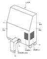
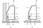
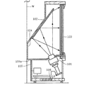
図1に示すように、電子機器であるプロジェクタ装置(背面投写型画像表示装置)の筐体10は、前面11には光像が投影されるスクリーンが設けられ、背面12の下部を壁にぴったりとつけて設置することのできる据置型の筐体構造を有する。また、前面側には、図3に示す前面転倒防止部材21、背面側には壁との間のスペースを検出する検出手段を構成する背面転倒防止部材31を備え、筐体10の内部には、従来例と同様の図示しない電子部品である投写管や反射鏡、回路部品等が内蔵される。筐体10の背面12は第1の排気口である背面排気口14、一方の側面13には第2の排気口である側面排気口15が設けられ、両排気口14、15から、図4に示す排気手段である冷却ファン16による冷却空気を排出自在である。
As shown in FIG. 1, a
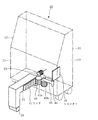
前面転倒防止部材21を摺動させながら、筐体10の底部を支えるキャスター22や背面転倒防止部材31のキャスター32を転動させて、室内の壁際に装置を設置するとき、背面12から突出する背面転倒防止部材31が壁に押されて筐体10の内部に引込まれると同時に、背面転倒防止部材31に連動して図2に示すシャッター手段であるシャッター45が回動し、背面排気口14による背面排気を側面排気口15による側面排気に切換えるように構成し、装置を壁にぴったりとつけて設置したときは側面排気のみによって内部冷却のための換気を行う。
When the
また図8に示すように、背面転倒防止部材31の進退に連動して、入出力端子61を回転させ、その接続面61aを背面側から側面側に切換える構成にすることにより、装置を壁にぴったりとつけて設置したときには側面側からの端子接続を可能にする。
In addition, as shown in FIG. 8, the input /
さらに図11に示すように、スクリーンにより画像表示を行う画像表示部を有する筐体上部の幅寸法より画像表示部の下方に配置される筐体下部の支持部の幅寸法が、少なくとも局部的に小さくなるように構成することにより、例えば2台横並びのプロジェクタ装置を壁にぴったりとつけて設置した場合でも側面排気のスペースを確保することができる。 Furthermore, as shown in FIG. 11, the width dimension of the support part at the lower part of the casing disposed below the image display part is at least locally than the width dimension of the upper part of the casing having the image display unit for displaying an image on the screen. By configuring the projector so as to be small, for example, even when two projector devices arranged side by side are installed in close contact with a wall, a side exhaust space can be secured.
図1に示すプロジェクタ装置の筐体10は、前述のように、内部に図示しない投写管、反射鏡、冷却ファン16等を有し、前面側にはスクリーンを備えている。筐体10が背面側に倒れるのを防止する背面転倒防止部材31は下向きのL型形状部材であり、その側面にはラック41が配設され、床面上のキャスター32と、図2に示すように筐体10内でその底面と接しているローラー34によって、筐体10の背面側の開口から出入自在である。背面転倒防止部材31は、一方を筐体10の内部に、他方を背面転倒防止部材31の内端に取付けた圧縮コイルバネ33によって筐体10の背面12から所定量だけ突出した位置に付勢されている。
As described above, the
ラック41とかみ合っているギア42aは、ギア42bおよびベルト43を介してシャッター軸44を回転させ、排気口切換え用のシャッター45を回動させて、背面排気口14と側面排気口15を交互に閉じることで、背面排気と側面排気の切換を行う。
The
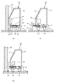
図3および図4は、キャスター22による筐体10の移動に伴うシャッター45の切換動作を説明するもので、筐体10内を冷却するための冷却ファン16による排気は、図3の(c)および図4の(c)に示すように、筐体10を壁面Wと離して設置した場合は、シャッター45が側面排気口15を塞いでいるので、冷却ファン16の排気は背面排気口14から放出される。
FIGS. 3 and 4 illustrate the switching operation of the
筐体10を壁面Wに近づけると、背面転倒防止部材31が壁面Wに押されて矢印A1で示すように筐体10内に収納されるため、筐体10の背面12を壁面Wにぴったりつけることが可能となる。このときシャッター45は、背面転倒防止部材31が壁面Wに押されて矢印A1で示すようにスライドし、背面転倒防止部材31の側面に配設されたラック41も同一方向に移動することにより、筐体10内のギア42a、42bがそれぞれ矢印A2、A3で示す方向に回転し、ベルト43によりシャッター軸44が回転する。これによって、排気方向切換え用のシャッター45が90度回転し、図3の(a)および図4の(a)に示すように背面排気口14を塞ぎ、側面排気口15を開口させるため、筐体10内を冷却する冷却ファン16による排気は筐体10の側面13に排出される。
When the
筐体10を壁面Wにぴったりつけた状態から、図3の(b)および図4の(b)に示すように後退させると、圧縮コイルバネ33の復元力により、背面転倒防止部材31が矢印B1で示す方向に押出される。つまり、壁面Wから離した距離だけ背面転倒防止部材31が押出され、その側面に配設されたラック41の逆方向の移動によって矢印B2、B3で示すようにギア42a、42bが逆転し、排気方向切換え用のシャッター45が逆向きに回動し、この間冷却ファン16は、側面排気口15と背面排気口14の双方から放熱する。さらに筐体10を壁面Wから離すと図3の(c)および図4の(c)に示す背面排気の状態となる。なお、本実施例では、背面転倒防止部材31を筐体10の内部に収納するように構成しているが、筐体10の外側に、例えば底面や側面13に沿って納めるように構成することも可能である。
When the
このように、壁面に装置をぴったりつけて設置した場合に、筐体側面に排気するように自動的に切換が行われる構成にすることで、据置型のプロジェクタ装置等の薄型化を大幅に促進し、設置スペースの有効利用に貢献できる。 In this way, when the device is installed tightly on the wall surface, it is automatically switched so that it is exhausted to the side of the housing, greatly reducing the thickness of stationary projector devices etc. And can contribute to the effective use of the installation space.
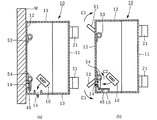
図5ないし図7は実施例2を示すもので、一対の背面転倒防止部材51、52が、筐体10の移動方向に直線的に引き込まれるのではなく、回転方向に引き込まれるように構成される。筐体10、前面転倒防止部材21、キャスター22、シャッター軸44、シャッター45については実施例1と同様であるから同一符号で表わし説明は省略する。
FIGS. 5 to 7 show the second embodiment, and the pair of rear surface
図5に示すように、筐体10の内部を冷却する空気の排気方向を切換えるためのシャッター45のシャッター軸44は、ベルト43を介して、一方の背面転倒防止部材52の回転と連動して回動自在であり、それぞれ上向きのL型形状をした背面転倒防止部材51、52は、床面をスライドし、コイルバネ53、54によって、筐体10の背面12から所定量だけ突出する回転位置に付勢されている。
As shown in FIG. 5, the
背面転倒防止部材52がコイルバネ54に抗して回転すると、ベルト43を介してシャッター軸44が回転し、実施例1と同様にシャッター45による背面排気と側面排気の切換が行われる。なお、コイルバネ53、54の一方の腕部53a、54aは筐体10に固定され、他方向の腕部53b、54bは背面転倒防止部材51、52にそれぞれ固定される。
When the backside
図6および図7は、背面転倒防止部材52に連動するシャッター45の排気方向切換動作を説明するもので、図6の(b)および図7の(b)に示すように、筐体10が壁面Wから離れているときは、筐体10の内部を冷却するための冷却ファン16は、筐体10の背面12に排気する。図6の(a)および図7の(a)に示すように、筐体10を壁面Wに近づけると、背面転倒防止部材51、52が壁に押されて筐体10の内部に収納されるため、筐体10は壁にぴったりつけることが可能となる。このとき、背面転倒防止部材52がコイルバネ54に抗して壁面Wに押されて、C1方向に回転し、ベルト43を介してシャッター軸44をC2方向に回転させることにより、シャッター45が背面排気口14を塞ぎ、側面排気口15が開かれて背面排気の状態となる。
FIGS. 6 and 7 illustrate the exhaust direction switching operation of the
筐体10を壁面Wにぴったりつけた後、壁から離すと、コイルバネ53、54の復元力により、筐体10内から背面転倒防止部材51、52が押出される。すなわち、壁から離した距離だけ背面転倒防止部材51、52が押出され、完全に背面転倒防止部材51、52が押出されると、図6の(b)および図7の(b)に示すようにシャッター45は再び背面排気の状態となる。背面転倒防止部材51、52が押出された場合でも、突起部が床面をスライドするため、邪魔になりにくい。
When the
なお、本実施例では、背面転倒防止部材51、52を筐体10の内部に収納しているが、筐体10の底面や側面13に沿って外側に収納される構成でもよい。
In the present embodiment, the backside
本実施例は、実施例1と同様に、筐体の背面を壁にぴったりつけて設置した場合には、自動的に側面排気に切換可能であり、しかも、完全に背面転倒防止部材が押し出された状態でも、背面転倒防止部材が床面近くに突出するため邪魔になりにくいという利点が付加される。 In the present embodiment, as in the first embodiment, when the rear surface of the housing is installed close to the wall, it can be automatically switched to the side exhaust, and the rear surface overturn prevention member is completely pushed out. Even in such a state, the backside fall-preventing member protrudes near the floor surface, so that an advantage that it does not get in the way is added.
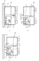
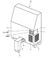
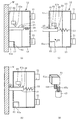
図8は実施例3を示すもので、筐体10に内蔵される電気回路を外部電源に接続するための入出力端子61の接続面61aを、筐体10の背面12に開口する第1の端子開口部と側面13に開口する第2の端子開口部を有する2方向開口型のL型開口17に露出させるとともに、入出力端子61を回転自在に筐体10内に取付け、筐体10を壁にぴったりとつけて設置した場合に、背面転倒防止部材31の移動に連動して入出力端子61を回転させ、側面から接続できるように構成したものである。筐体10、前面転倒防止部材21、背面転倒防止部材31等については実施例1と同様であるから同一符号で表わし説明は省略する。なお、背面排気口14と側面排気口15による排気方向を切換えるための排気切換機構42a〜44およびシャッター45については、説明を簡単にするために省略した。
FIG. 8 shows a third embodiment, in which a
図9は、背面転倒防止部材31の移動に連動して入出力端子61の接続面61aの方向を切換える機構を説明するもので、壁検出スイッチ62は、背面転倒防止部材31の後端に設けられた突起部35によって押圧されるレバー62aを有する。
FIG. 9 illustrates a mechanism for switching the direction of the
図9の(c)に示す状態から筐体10が壁に向かって移動するとともに、背面転倒防止部材31が壁によって矢印D1で示す方向に押されて、突起部35がレバー62aから離れると、壁検出スイッチ62から同図の(d)に示す端子回転手段であるモーター63に駆動信号が送信され、モーター軸に取付けられたギア63aおよび入出力端子61のギア61bを介して、入出力端子61を矢印D2で示すように回転させ、接続面61aの露出方向を同図の(a)で示すように側面側に切換る。
When the
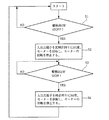
上記の切換動作を図10のフローチャートに基づいて説明する。プロジェクタ装置を壁から離して設置した図9の(c)に示す状態から筐体を壁に近づける工程で、まず、壁を検出する壁検出スイッチがOFFされているかの確認を行う(ステップS1)。壁検出スイッチがONされている場合には、スタートに戻る。壁検出スイッチがOFFされている場合には、駆動信号をモーターに送信して、入出力端子を反時計回り、すなわちD2方向に90度回転させ、入出力端子の接続面を側面に向ける(ステップS2)。次に、図9の(b)に示すように筐体を壁から離間させ、背面転倒防止部材が矢印E1で示す方向に突出する過程で、壁を検出する壁検出スイッチがONされているかの確認を行う(ステップS3)。壁検出スイッチがOFFされている場合には、モーターを駆動しない。壁検出スイッチがONされている場合には、駆動信号をモーターに送信して、入出力端子を時計回り、すなわちD2 方向と逆向きに90度回転させ(ステップS4)、図9の(c)に示すように入出力端子を背面に向け、スタートに戻る。 The above switching operation will be described with reference to the flowchart of FIG. In the step of bringing the housing close to the wall from the state shown in FIG. 9C where the projector apparatus is installed away from the wall, first, it is confirmed whether the wall detection switch for detecting the wall is turned off (step S1). . If the wall detection switch is ON, the process returns to the start. When the wall detection switch is OFF, a drive signal is transmitted to the motor, the input / output terminal is rotated counterclockwise, that is, rotated 90 degrees in the D2 direction, and the connection surface of the input / output terminal faces the side (step) S2). Next, as shown in FIG. 9 (b), whether the wall detection switch for detecting the wall is turned on in the process in which the casing is separated from the wall and the rear surface fall prevention member protrudes in the direction indicated by the arrow E1. Confirmation is performed (step S3). When the wall detection switch is OFF, the motor is not driven. If the wall detection switch is ON, and transmits a drive signal to the motor, clockwise output terminals, i.e. rotated 90 degrees in the D 2 direction opposite (step S4), (c in FIG. 9 ) Turn the input / output terminals to the back as shown in) and return to the start.
このような構成にすることにより、筐体を壁にぴったりつけて設置した場合には、入出力端子を回転させ、側面に接続可能とすることができる。 By adopting such a configuration, when the casing is placed close to the wall, the input / output terminal can be rotated and can be connected to the side surface.
なお、背面転倒防止部材と一体であるラックによる排気切換機構の代わりに、壁検出スイッチの出力によってシャッターが回動する構成にすることもできる。 In addition, it can also be set as the structure which a shutter rotates by the output of a wall detection switch instead of the exhaust_gas | exhaustion switching mechanism by the rack integral with a back surface fall prevention member.
図11は実施例4を示すもので、筐体10と同様の筐体70の筐体上部70aと筐体下部70bの幅寸法が同一ではなく、筐体上部70aより筐体下部70bの幅を小さくすることで、2台横並び配置した場合でも、側面排気口75による側面排気を可能とするものである。
FIG. 11 shows the fourth embodiment. The width of the case
2台横並び配置したプロジェクタ装置を壁にぴったりとつけて設置した場合でも、側面排気をする空間が存在するので、幅方向の設置スペースを最小限に抑えてスペースの有効利用に貢献できる。 Even when two projectors arranged side by side are installed close to the wall, there is a space for exhausting from the side, so the installation space in the width direction can be minimized to contribute to effective use of the space.
プロジェクタ装置のみならず、内部冷却のための排気を必要とする据置型の電子機器の筐体構造に広く適用できる。 The present invention can be widely applied not only to a projector device but also to a housing structure of a stationary electronic device that requires exhaust for internal cooling.
10、70 筐体
11 前面
12 背面
13 側面
14 背面排気口
15、75 側面排気口
16 冷却ファン
17 L型開口
21 前面転倒防止部材
22、32 キャスター
31、51、52 背面転倒防止部材
34 ローラー
35 突起部
41 ラック
44 シャッター軸
45 シャッター
53、54 コイルバネ
61 入出力端子
61a 接続面
62 壁検出スイッチ
62a レバー
63 モーター
DESCRIPTION OF
Claims (5)
Priority Applications (1)
| Application Number | Priority Date | Filing Date | Title |
|---|---|---|---|
| JP2004103214A JP2005292210A (en) | 2004-03-31 | 2004-03-31 | Electronic apparatus enclosure structure and projector device |
Applications Claiming Priority (1)
| Application Number | Priority Date | Filing Date | Title |
|---|---|---|---|
| JP2004103214A JP2005292210A (en) | 2004-03-31 | 2004-03-31 | Electronic apparatus enclosure structure and projector device |
Publications (1)
| Publication Number | Publication Date |
|---|---|
| JP2005292210A true JP2005292210A (en) | 2005-10-20 |
Family
ID=35325247
Family Applications (1)
| Application Number | Title | Priority Date | Filing Date |
|---|---|---|---|
| JP2004103214A Pending JP2005292210A (en) | 2004-03-31 | 2004-03-31 | Electronic apparatus enclosure structure and projector device |
Country Status (1)
| Country | Link |
|---|---|
| JP (1) | JP2005292210A (en) |
Cited By (3)
| Publication number | Priority date | Publication date | Assignee | Title |
|---|---|---|---|---|
| JP2008124708A (en) * | 2006-11-10 | 2008-05-29 | Sharp Corp | Thin display mounting table |
| JP2014098738A (en) * | 2012-11-13 | 2014-05-29 | Mitsubishi Electric Corp | Image projection device |
| CN112073702A (en) * | 2020-09-27 | 2020-12-11 | 广州睿喑科技有限公司 | Projection equipment for report display with working state abnormity reminding function |
-
2004
- 2004-03-31 JP JP2004103214A patent/JP2005292210A/en active Pending
Cited By (4)
| Publication number | Priority date | Publication date | Assignee | Title |
|---|---|---|---|---|
| JP2008124708A (en) * | 2006-11-10 | 2008-05-29 | Sharp Corp | Thin display mounting table |
| JP2014098738A (en) * | 2012-11-13 | 2014-05-29 | Mitsubishi Electric Corp | Image projection device |
| US9547221B2 (en) | 2012-11-13 | 2017-01-17 | Mitsubishi Electric Corporation | Video projection device |
| CN112073702A (en) * | 2020-09-27 | 2020-12-11 | 广州睿喑科技有限公司 | Projection equipment for report display with working state abnormity reminding function |
Similar Documents
| Publication | Publication Date | Title |
|---|---|---|
| US7441903B2 (en) | Power on/off system of thin projector and method for controlling the same | |
| JP2001249402A (en) | Display device and display system using the same | |
| JP4378658B2 (en) | Light source chamber housing light source device and projector having the light source chamber | |
| US6709115B2 (en) | Projector | |
| US6886948B2 (en) | Electronics exterior case and projector having the same | |
| JP2005092098A (en) | Liquid crystal projector | |
| US7543942B2 (en) | Automatic door mechanism for projector | |
| JPH10260473A (en) | Method for projecting video on screen, projection type video projector, and fixture | |
| JP2008170808A (en) | Dust-collecting mechanism, projection image display apparatus and electronic apparatus | |
| JP2005292210A (en) | Electronic apparatus enclosure structure and projector device | |
| TW201007336A (en) | Projector with heat insulating construction | |
| JP2009181113A (en) | Projector | |
| JP3512745B2 (en) | Light source device and projector using the same | |
| JP2001343708A (en) | Cooling mechanism for back projection type display apparatus | |
| JP4023490B2 (en) | Image display projector | |
| JP2006195319A (en) | Projector | |
| JP2009115967A (en) | Projector | |
| JP2002372747A (en) | Projection type display device | |
| JP5035597B2 (en) | projector | |
| JP2002236318A (en) | Structure of light shielding slit part of projection type image display device, and controller of light shielding slit part | |
| JP3827644B2 (en) | Projector device | |
| JP2006162840A (en) | Light source unit having exhaust structure and projector using the same | |
| JP2011180187A (en) | Projection type image display device | |
| JP5041216B2 (en) | projector | |
| JP4079868B2 (en) | Exhaust mechanism, electronic equipment, projector |