JP6091133B2 - Projection type display device, control method used therefor, and program - Google Patents
Projection type display device, control method used therefor, and program Download PDFInfo
- Publication number
- JP6091133B2 JP6091133B2 JP2012217188A JP2012217188A JP6091133B2 JP 6091133 B2 JP6091133 B2 JP 6091133B2 JP 2012217188 A JP2012217188 A JP 2012217188A JP 2012217188 A JP2012217188 A JP 2012217188A JP 6091133 B2 JP6091133 B2 JP 6091133B2
- Authority
- JP
- Japan
- Prior art keywords
- image
- menu image
- projection
- display device
- region
- Prior art date
- Legal status (The legal status is an assumption and is not a legal conclusion. Google has not performed a legal analysis and makes no representation as to the accuracy of the status listed.)
- Expired - Fee Related
Links
Images


Description
本発明は、液晶プロジェクタ等の投射型表示装置に関し、特に、メニュー画像の表示に関するものである。 The present invention relates to a projection display device such as a liquid crystal projector, and more particularly to display of a menu image.
従来、メニュー画像の表示位置を移動させることが可能な投射型表示装置がある。特許文献1には、表示画面の周囲の状況に応じた、使いやすい位置に操作キーを表示する方法が開示されている。
2. Description of the Related Art Conventionally, there is a projection display device that can move the display position of a menu image.
しかし、黒板やホワイトボード等をスクリーンとして用いて画像を投射する場合、スクリーン上に書かれている文字とメニュー画像が重畳し、メニュー画像の視認性が低下してしまっていた。 However, when an image is projected using a blackboard, whiteboard, or the like as a screen, the text written on the screen and the menu image are superimposed, and the visibility of the menu image is reduced.
また、投射型表示装置のエッジブレンド機能を用いる際に、メニュー画像の視認性が低下してしまうという他の課題があった。 Further, when using the edge blend function of the projection display device, there is another problem that the visibility of the menu image is lowered.
上記課題を解決するために、本発明の投射型表示装置は、
光変調素子により変調された光を被投射面に投射する投射型表示装置であって、
投射画像を撮像する撮像手段と、
前記撮像手段により撮像された撮像画像が含む複数の領域のうち、空間周波数が最も低い領域を探索する探索手段と、
前記探索手段により探索された領域にメニュー画像を表示する表示手段を有し、前記複数の領域に対して優先度が設定されており、前記複数の領域のうち、空間周波数が最も低い領域が複数存在する場合には、該複数存在する領域のうち、優先度が最も高い領域にメニュー画像を表示することを特徴とする。
In order to solve the above problems, a projection display device of the present invention is
A projection display device that projects light modulated by a light modulation element onto a projection surface,
Imaging means for capturing a projected image;
Search means for searching for an area having the lowest spatial frequency among a plurality of areas included in the captured image captured by the imaging means;
It has a display means for displaying a menu image in a region which is searched by the search means, wherein are set the priority for a plurality of regions, the plurality of regions, the lowest region spatial frequency more If present, a menu image is displayed in a region having the highest priority among the plurality of regions .
本発明の他の一側面としてのプログラムは、
投射画像を撮像可能な撮像手段を有する投射型表示装置に、
投射画像を撮像する撮像ステップと、
前記探索ステップにおいて探索された領域にメニュー画像を表示する際、前記複数の領域に対して優先度が設定されており、空間周波数が最も低い領域が複数存在する場合には、該複数存在する領域のうち、優先度が最も高い領域にメニュー画像を表示する表示ステップを実行させることを特徴とする。
A program as another aspect of the present invention is:
In a projection type display device having an imaging means capable of capturing a projection image,
An imaging step of capturing a projected image;
When a menu image is displayed in the area searched in the search step, when priority is set for the plurality of areas and there are a plurality of areas having the lowest spatial frequency, the plurality of areas exist. Among them, a display step of displaying a menu image in a region having the highest priority is executed.
本発明の他の一側面としてのプログラムは、
光変調素子により変調された光を被投射面に投射する投射型表示装置に、
前記投射型表示装置が投射する画像と他の投射型表示装置が投射する画像とが重畳する領域と、メニュー画像の表示領域と、が重ならない位置に、メニュー画像を移動するステップを実行させることを特徴とするプログラム。
A program as another aspect of the present invention is:
In a projection display device that projects light modulated by a light modulation element onto a projection surface,
Executing the step of moving the menu image to a position where the area where the image projected by the projection display apparatus and the image projected by another projection display apparatus overlap and the display area of the menu image do not overlap. A program characterized by
本発明によれば、文字等が書かれたスクリーン上に画像を投射する場合においても、メニュー画像の視認性を低下させない位置にメニューを表示することを可能にした投射型表示装置を提供することができる。 According to the present invention, even when an image is projected on a screen on which characters or the like are written, a projection display device that can display a menu at a position where the visibility of the menu image is not deteriorated is provided. Can do.
また、本発明の他の効果として、投射型表示装置のエッジブレンド機能を用いる際に、メニュー画像の視認性を低下させない位置にメニューを表示することができる。 As another effect of the present invention, when the edge blend function of the projection display device is used, the menu can be displayed at a position where the visibility of the menu image is not lowered.
《実施形態1》
図1は、本発明の実施形態1の投射型表示装置100の概略構成図である。投射型表示装置100において、光源101からの光は、照明光学系102、色分解合成系103を介して液晶パネル等の光変調素子へ導かれる。光変調素子は、入力画像信号に応じて入射光を変調する。変調された光は、投射レンズ104を介してスクリーン等の被投射面に投射される。記憶部107は、投射画像に重畳されるメニュー画像そのもの(後述する基準メニュー画像に相当)や、メニュー画像の表示位置や、後述する分割領域に関する情報等を記憶する。制御部105は、例えば、マイクロコンピュータであり、投射型表示装置100の各部を制御する。撮像部106は、投射画像が撮像可能なように投射型表示装置100に設けられている。
FIG. 1 is a schematic configuration diagram of a
図2は、実施形態1のメニュー画像の表示位置の決定に関するフローチャートである。このフローチャートは、リモコン等の操作部を介して使用者からメニュー画像を表示する指示を受け付けると開始される。 FIG. 2 is a flowchart regarding determination of the display position of the menu image according to the first embodiment. This flowchart is started when an instruction to display a menu image is received from a user via an operation unit such as a remote controller.
まず、ステップS101において、制御部105はメニュー画像を表示する指示を受けると、記憶部107に記憶されたメニュー画像の表示位置にメニュー画像を表示させてステップS102に進む。
First, in step S101, when the
ステップS102おいて、制御部105は、次のステップにおいて投射領域を検出するためのパターン画像を表示させた状態で撮像部106に撮像を指示する。撮像部106による撮像が完了するとステップS103に進む。ここで、図3に、撮像部106が撮像する画、つまり、使用者が目にしているスクリーン上の画を示す。黒で示した部分は、投射型表示装置100によってスクリーン上に投射されている画像(文字)であり、グレーで示した部分は、使用者によってスクリーンに書かれた文字である。図3の画を、投射型表示装置100によってスクリーン上に投射されている画像(文字)と直接スクリーンに書かれた文字とに分けたものを図4、図5に示す。
In step S102, the
ステップS102における撮像が完了すると、ステップS103において、制御部105は、撮像した画像(撮像画像)から投射型表示装置100が画像を投射している領域を検出する。
When the imaging in step S102 is completed, in step S103, the
ステップS104において、制御部105は、ステップS103において検出した領域に対して射影変換を行い、歪んだ画像を、正面から見た画像(長方形の画像)へと変換する。
In step S104, the
次に、ステップS105において、制御部105は、射影変換した画像に対し、微分処理を行う。微分処理とは、例えば、隣接する画素の画素値の差から、画素間の微分値(傾き量)を求める処理である。
Next, in step S <b> 105, the
ステップS106において、制御部105は、微分処理の結果を用いて、図6(a)に示すような微分量マップを作成する。図6(a)に示す各分割領域は、射影変換した画像における、特定のメニュー表示位置におけるメニュー画像が占める領域であり、各分割領域に示された値は、分割領域内の画素の微分値を足し合わせた総微分量(総微分値)である。本実施形態においては、ステップS101において表示されたメニュー画像の表示位置は、分割領域M1に対応する位置であるとする。
In step S106, the
次に、ステップS107において、制御部105は、作成した微分量マップから、総微分量の最も少ない分割領域(メニュー画像の表示位置)を探索する。
Next, in step S <b> 107, the
ステップS108において、制御部105は、探索結果に基づき、総微分量の最も少ない位置にメニュー画像を表示する。本実施形態においては、図6(a)の分割領域M2の総微分量が最も少ない0(ゼロ)であるので、分割領域M2に対応する位置がメニュー画像の表示に最適な位置と判断され、そこにメニュー画像が表示される。
In step S108, the
本実施形態によれば、文字等が書かれた被投射面に重畳して画像を投射する場合においても、メニュー画像の視認性を低下させない位置にメニューを表示することができる。 According to the present embodiment, the menu can be displayed at a position where the visibility of the menu image is not deteriorated even when the image is projected while being superimposed on the projection surface on which characters or the like are written.
本実施形態のステップS106において示した図6(a)は、説明用に簡略化したものであり、微分量マップを作成する際のマトリックスの数は5×5に限られず、メニュー画像の大きさに合わせて変更することができる。また、複数の分割領域は、求める視認性の高さに応じて、互いに重なっていてもよい。また、射影変換した画像のすべての領域を分割領域が占める必要はなく、分割領域を画像の周辺部のみとする設定としてもよい。本実施形態においては、各分割領域は、あらかじめ設定されているものとするが、使用者が設定できるようにしてもよい。 FIG. 6A shown in step S106 of the present embodiment is simplified for explanation, and the number of matrices when creating the differential quantity map is not limited to 5 × 5, and the size of the menu image is shown. It can be changed to suit. Further, the plurality of divided regions may overlap each other depending on the required high visibility. Further, it is not necessary for the divided areas to occupy all the areas of the projective transformed image, and the divided areas may be set to be only the peripheral portion of the image. In the present embodiment, each divided area is set in advance, but may be set by the user.
また、本実施形態においては、微分値の総和を、メニュー画像の表示位置を決定する際のパラメータとして用いたが、空間周波数の低い領域が特定できる方法であれば、微分値を用いる方法に限られない。また、微分量マップを作成する際に、微分値の総和を用いたが、これに限られず、微分処理によって求められる各画素間の微分値(傾き量)を表す直線、或いは、それを近似した曲線の滑らかさを表すパラメータを用いて、メニュー画像の表示位置を探索してもよい。 In the present embodiment, the sum of the differential values is used as a parameter when determining the display position of the menu image. However, the method using the differential values is limited as long as the method can identify a region having a low spatial frequency. I can't. In addition, the total sum of the differential values was used when creating the differential amount map, but the present invention is not limited to this. A straight line representing the differential value (inclination amount) between each pixel obtained by the differential processing or an approximation thereof. You may search the display position of a menu image using the parameter showing the smoothness of a curve.
また、本実施形態においては、射影変換をした画像に対してメニュー画像の表示位置を探索する形態について説明したが、射影変換をする前の画像、即ち撮像画像に対してメニュー画像の表示位置を探索してもよい。 In the present embodiment, the form of searching for the display position of the menu image with respect to the image subjected to the projective transformation has been described. You may search.
《実施形態2》
図7は、本発明の実施形態2の投射型表示装置700の概略構成図である。実施形態1と異なる点は、投射型表示装置700が撮像部106を有していない点、メニュー画像を表示する際に、エッジブレンド領域とメニュー画像とが重ならないようにメニュー画像の表示位置を制御する点である。
<< Embodiment 2 >>
FIG. 7 is a schematic configuration diagram of a
投射型表示装置700において、光源701からの光は、照明光学系702、色分解合成系703を介して液晶パネル等の光変調素子へ導かれる。光変調素子は、入力画像信号に応じて入射光を変調する。変調された光は、投射レンズ704を介してスクリーン等の被投射面に投射される。記憶部707は、投射画像に重畳されるメニュー画像そのもの(後述する基準メニュー画像に相当)や、メニュー画像の表示位置や、後述する分割領域に関する情報等を記憶する。制御部705は、例えば、マイクロコンピュータであり、投射型表示装置700の各部を制御する。
In the
ここで、エッジブレンド領域(重畳領域)とは、投射型表示装置700と他の投射型表示装置を並べて1つの画像を投射する場合に、投射型表示装置700が投射する画像と他の投射型表示装置が投射する画像とが重なる領域のことである。近年、大きな画像を投射するために、2つ以上の投射型表示装置を並べて1つの画像を投射することが多い。そこで、設置者が適切に各投射型表示装置を設置可能なように、エッジブレンド領域が使用者に分かるように表示する機能や、設置の状況に合わせてエッジブレンド領域の幅を変更する機能が投射型表示装置に設けられているものがある。また、投射型表示装置700が投射する画像と他の投射型表示装置が投射する画像をそのまま重ね合わせると、エッジブレンド領域が明るくなってしまうので、エッジブレンド領域の階調値を自動的に調整する機能がある。
Here, the edge blend region (superimposition region) is an image projected by the
そして、これら機能の有効、無効を使用者が選択可能になっているものが多い。本実施形態におけるエッジブレンドとは、投射型表示装置700が投射する画像と他の投射型表示装置が投射する画像とが重なる領域(エッジブレンド領域)の階調値を自動的に調整する機能のことである。
In many cases, the user can select whether these functions are enabled or disabled. The edge blend in this embodiment is a function of automatically adjusting the gradation value of an area (edge blend area) where an image projected by the
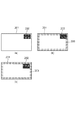
図8(a)はエッジブレンドが無効である際にメニュー画像202が表示領域201の端に表示されている状態を示す。この状態において、エッジブレンドを有効にして、メニュー画像202の位置の変更をしないと、図8(b)のように、メニュー画像202とエッジブレンド領域203が重なり、メニュー画像202の視認性が低下してしまう。
FIG. 8A shows a state in which the
そこで、本実施形態においては、図8(c)のように、エッジブレンドを有効にする際に、メニュー画像202とエッジブレンド領域203が重なりあう量だけメニュー画像の位置を表示領域の内側に移動させる。
Therefore, in the present embodiment, as shown in FIG. 8C, when the edge blending is enabled, the position of the menu image is moved to the inside of the display region by an amount that the
図9(a)は、エッジブレンドが有効で、エッジブレンド領域203に沿ってメニューが表示されている状態である。この状態から、エッジブレンド領域の幅を変更すると、図9(b)のようにメニュー画像202とエッジブレンド領域203が重なり、メニュー画像202の視認性が低下してしまう。
FIG. 9A shows a state in which edge blending is effective and a menu is displayed along the
そこで、図9(c)のように、エッジブレンド領域の幅の変更量に合わせてメニュー画像202を表示領域の内側に移動させる。
Therefore, as shown in FIG. 9C, the
本実施形態によれば、エッジブレンドが有効とされた際、あるいは、エッジブレンド領域の幅が変更された際においても、メニュー画像の視認性を低下させない位置にメニュー画像を表示することができる。 According to the present embodiment, the menu image can be displayed at a position where the visibility of the menu image is not deteriorated even when the edge blending is enabled or the width of the edge blend region is changed.
《実施形態3》
本発明の実施形態3の投射型表示装置は、図1と同様の構成を有する。実施形態1と異なる点は、微分量マップから総微分量が最も少ないメニュー画像の表示位置を探索することに加えて、メニュー画像の表示位置の優先度に応じて、メニュー画像の表示位置を決定する点である。本実施形態における微分量マップの一例を図6(b)に示す。
<<
The projection type display apparatus of
まず、図2のステップS107における探索ステップにおいて、記憶部107に記憶されているメニュー画像の表示位置から探索を開始する。ここで、記憶部107に記憶されているメニュー画像の表示位置は、図6(b)の分割領域Aに対応する位置だったとすると、制御部105は、始めに分割領域Aから探索を開始する。そして、次は右の分割領域B、下の分割領域C、左の分割領域Dと、時計回りで順に探索する。そして、その中で、空間周波数が最も低い分割領域で、且つ、探索順の早い位置を最適なメニュー表示位置とする。即ち、本実施形態における、優先度とは探索順序であり、探索順序が早い分割領域ほど優先度が高い。本実施形態において空間周波数が最も低い領域は複数存在するが、制御部105は、優先度が最も高い分割領域Aに対応する位置に、メニュー画像を表示する。
First, in the search step in step S107 of FIG. 2, the search is started from the display position of the menu image stored in the
本実施形態によれば、文字等が書かれた被投射面に画像を投射する場合においても、メニュー画像の視認性を低下させない位置にメニューを表示することができる。 According to this embodiment, even when an image is projected on a projection surface on which characters or the like are written, the menu can be displayed at a position where the visibility of the menu image is not lowered.
本実施形態においては、優先度として探索の順序を例に挙げたが、これに限られず、各分割領域に優先度を設定して、空間周波数が最も低い分割領域であって、且つ、優先度が最も高い位置を、最終的にメニュー画像を表示する位置として設定してもよい。 In the present embodiment, the search order is given as an example of priority as an example of priority, but the present invention is not limited to this. The priority is set for each divided region, the divided region having the lowest spatial frequency, and the priority. May be set as the position where the menu image is finally displayed.
本実施形態のように、記憶部107が記憶するメニュー画像の表示位置を含む分割領域Aの優先度を、最も高い優先度に設定することで、メニュー画像の表示位置が大きく変わってしまうことを抑えられるので、より好ましい。
As in the present embodiment, setting the priority of the divided area A including the display position of the menu image stored in the
《実施形態4》
実施形態4の投射型表示装置は図1と同様の構成を有する。実施形態4は、実施形態1で説明したメニュー画像の表示位置の探索処理を行うか(有効)行わないか(無効)を選択する選択手段をさらに有する。
<<
The projection type display apparatus of
実施形態4の制御のフローチャートについて説明する。実施形態1と同様に、使用者によりメニュー画像の表示が指示されると開始される。 A control flowchart according to the fourth embodiment will be described. As in the first embodiment, the process is started when the user instructs display of the menu image.
まず、使用者からメニュー画像の表示指示を受けると、制御部105は、メニュー画像の表示位置の探索処理を行う設定が有効となっているか無効となっているかを確認する。無効の設定となっている場合、制御部105は、記憶部107からメニュー画像の表示位置を読み出し、その位置にメニュー画像を表示する。一方、有効の設定となっている場合、制御部105は、実施形態1のフローチャートに基づく制御を行い、空間周波数が最も低い領域に対応する位置に、メニュー画像を表示する。
First, upon receiving a menu image display instruction from the user, the
メニュー画像の表示位置の探索処理の有効又は無効は、使用者が操作部を操作することによって選択される。 The validity or invalidity of the search processing for the display position of the menu image is selected by the user operating the operation unit.
《実施形態5》
実施形態5の投射型表示装置は図1と同様の構成を有する。実施形態1と異なる点は、実施形態1によるメニュー画像の表示後に、表示されたメニューの視認性に応じて再探索を行う点である。
<< Embodiment 5 >>
The projection display apparatus of Embodiment 5 has the same configuration as that in FIG. The difference from the first embodiment is that after the menu image is displayed according to the first embodiment, a re-search is performed according to the visibility of the displayed menu.
図10は、再探索を行う際のフローチャートである。本フローチャートは、実施形態1のフローの後に、実行することが可能なフローチャートである。 FIG. 10 is a flowchart for performing re-search. This flowchart is a flowchart that can be executed after the flow of the first embodiment.
まず、ステップS301は、実施形態1の方法で決定された位置にメニュー画像が表示されている状態であるとする。ここで、実施形態1の方法で決定された位置にメニュー画像の表示位置は、不図示の分割領域Xに対応する位置であったとする。 First, step S301 is a state in which the menu image is displayed at the position determined by the method of the first embodiment. Here, it is assumed that the display position of the menu image at the position determined by the method of the first embodiment is a position corresponding to a divided area X (not shown).
ステップS302において、制御部105は、再度、投射画像の撮像を行い、投射領域を検出し、撮像画像の射影変換を行う。
In step S302, the
ステップS303において、制御部105は、射影変換を行った画像から、メニュー画像を検出し、検出されたメニュー画像(以下、撮像メニュー画像)と記憶部107が保持しているメニュー画像(以下、基準メニュー画像)との比較を行う。具体的には、撮像メニュー画像と基準メニュー画像との差を演算する。本実施形態における差とは、撮像メニュー画像と基準メニュー画像との対応する画素の値の差の絶対値の和をとった値とする。
In step S303, the
ステップS304において、制御部105は、撮像メニュー画像と基準メニュー画像との差があらかじめ設定された閾値を越えている場合(図中YESの場合)、ステップS305へ進む。ステップS305では、ステップS301においてメニュー画像が表示された位置に対応する分割領域Xの総微分量を最大値に設定し、分割領域X以外の領域(メニュー画像が表示されている領域以外の領域)で、総微分量が最も少ない領域を再度、探索する。そして、探索後はステップS301へと戻る。
In step S304, if the difference between the captured menu image and the reference menu image exceeds a preset threshold value (YES in the figure), the
一方、撮像メニュー画像と基準メニュー画像との差が閾値を越えていない場合(図中NOの場合)、ステップS306へ進み、ステップS301においてメニュー画像が表示されていた位置を記憶部107に記憶して、本フローを終了する。
On the other hand, when the difference between the captured menu image and the reference menu image does not exceed the threshold value (in the case of NO in the figure), the process proceeds to step S306, and the position where the menu image was displayed in step S301 is stored in the
本実施形態においては、より視認性の良いメニュー画像を表示させることができる。 In the present embodiment, a menu image with better visibility can be displayed.
実施形態5においては、撮像メニュー画像と基準メニュー画像との差が閾値を越えているか否かに基づき、再探索を行うか否かを判断したが、これに限られない。例えば、撮像メニュー画像と基準メニュー画像との相関をとることによって類似度を計算し、類似度が高いか低いかに基づいて再探索を行うか否かを判断してもよい。 In the fifth embodiment, whether or not to perform a re-search is determined based on whether or not the difference between the captured menu image and the reference menu image exceeds a threshold value, but is not limited thereto. For example, the similarity may be calculated by taking a correlation between the captured menu image and the reference menu image, and it may be determined whether to perform a re-search based on whether the similarity is high or low.
《他の実施形態》
また、本発明は、以下の処理を実行することによっても実現される。即ち、上述した実施形態の機能を実現するソフトウェア(プログラム)を、ネットワーク又は各種記憶媒体を介してシステム或いは装置に供給し、そのシステム或いは装置のコンピュータ(またはCPUやMPU等)がプログラムを読み出して実行する処理である。
<< Other embodiments >>
The present invention can also be realized by executing the following processing. That is, software (program) that realizes the functions of the above-described embodiments is supplied to a system or apparatus via a network or various storage media, and a computer (or CPU, MPU, or the like) of the system or apparatus reads the program. It is a process to be executed.
100 投射型表示装置
105 制御部
106 撮像部
DESCRIPTION OF
Claims (9)
投射画像を撮像する撮像手段と、
前記撮像手段により撮像された撮像画像が含む複数の領域のうち、空間周波数が最も低い領域を探索する探索手段と、
前記探索手段により探索された領域にメニュー画像を表示する表示手段を有し、
前記複数の領域に対して優先度が設定されており、前記複数の領域のうち、空間周波数が最も低い領域が複数存在する場合には、該複数存在する領域のうち、優先度が最も高い領域にメニュー画像を表示することを特徴とする投射型表示装置。 A projection display device that projects light modulated by a light modulation element onto a projection surface,
Imaging means for capturing a projected image;
Search means for searching for an area having the lowest spatial frequency among a plurality of areas included in the captured image captured by the imaging means;
Have a display means for displaying a menu image in a region which is searched by the searching means,
If priority is set for the plurality of regions, and there are a plurality of regions having the lowest spatial frequency among the plurality of regions, the region having the highest priority among the plurality of regions present A projection-type display device that displays a menu image on the screen .
前記探索手段は、前記射影変換された画像において、前記空間周波数が最も低い領域を探索することを特徴とする請求項1に記載の投射型表示装置。 Having a projective transformation means for projective transformation of the projected image taken by the imaging means;
The projection display device according to claim 1, wherein the search unit searches for a region having the lowest spatial frequency in the projective transformed image.
前記記憶部が記憶するメニュー画像の表示位置を含む領域の優先度を、最も高い優先度に設定することを特徴とする請求項1乃至3に記載の投射型表示装置。 A storage unit for storing the display position of the menu image;
Projection display device according to claim 1 to 3, characterized in that the priority of a region including the display position of the menu image which the storage unit stores, set the highest priority.
撮像されたメニュー画像と記憶部に記憶された基準のメニュー画像との差が閾値を越える場合、前記探索手段は、メニュー画像が表示されている領域以外の領域のうち空間周波数が最も低い領域を再度、探索し、
前記表示手段は、再度の探索によって探索された領域にメニュー画像を表示させることを特徴とする請求項1乃至5のいずれか1項に記載の投射型表示装置。 The imaging unit captures again the menu image displayed by the display unit,
When the difference between the captured menu image and the reference menu image stored in the storage unit exceeds the threshold, the search means selects the region having the lowest spatial frequency among the regions other than the region where the menu image is displayed. Explore again,
The display means, the projection type display device according to any one of claims 1 to 5, characterized in that displaying a menu image is searched by the search again region.
前記投射型表示装置が投射する画像と他の投射型表示装置が投射する画像とが重畳する領域と、メニュー画像の表示領域と、が重ならない位置に、メニュー画像を移動する制御手段を有することを特徴とする投射型表示装置。 A projection display device that projects light modulated by a light modulation element onto a projection surface,
Control means for moving the menu image to a position where the area where the image projected by the projection display apparatus and the image projected by another projection display apparatus overlap and the display area of the menu image do not overlap. Projection type display device characterized by the above.
投射画像を撮像する撮像ステップと、
前記撮像ステップにおいて撮像された撮像画像が含む複数の領域のうち、空間周波数が最も低い領域を探索する探索ステップと、
前記探索ステップにおいて探索された領域にメニュー画像を表示する際、前記複数の領域に対して優先度が設定されており、空間周波数が最も低い領域が複数存在する場合には、該複数存在する領域のうち、優先度が最も高い領域にメニュー画像を表示する表示ステップを実行させることを特徴とするプログラム。 In a projection type display device having an imaging means capable of capturing a projection image,
An imaging step of capturing a projected image;
A search step for searching for a region having the lowest spatial frequency among a plurality of regions included in the captured image captured in the imaging step;
When a menu image is displayed in the area searched in the search step, when priority is set for the plurality of areas and there are a plurality of areas having the lowest spatial frequency, the plurality of areas exist. A program for executing a display step of displaying a menu image in an area having the highest priority .
前記投射型表示装置が投射する画像と他の投射型表示装置が投射する画像とが重畳する領域と、メニュー画像の表示領域と、が重ならない位置に、メニュー画像を移動するステップを実行させることを特徴とするプログラム。Executing the step of moving the menu image to a position where the area where the image projected by the projection display apparatus and the image projected by another projection display apparatus overlap and the display area of the menu image do not overlap. A program characterized by
Priority Applications (1)
| Application Number | Priority Date | Filing Date | Title |
|---|---|---|---|
| JP2012217188A JP6091133B2 (en) | 2012-09-28 | 2012-09-28 | Projection type display device, control method used therefor, and program |
Applications Claiming Priority (1)
| Application Number | Priority Date | Filing Date | Title |
|---|---|---|---|
| JP2012217188A JP6091133B2 (en) | 2012-09-28 | 2012-09-28 | Projection type display device, control method used therefor, and program |
Publications (2)
| Publication Number | Publication Date |
|---|---|
| JP2014072699A JP2014072699A (en) | 2014-04-21 |
| JP6091133B2 true JP6091133B2 (en) | 2017-03-08 |
Family
ID=50747526
Family Applications (1)
| Application Number | Title | Priority Date | Filing Date |
|---|---|---|---|
| JP2012217188A Expired - Fee Related JP6091133B2 (en) | 2012-09-28 | 2012-09-28 | Projection type display device, control method used therefor, and program |
Country Status (1)
| Country | Link |
|---|---|
| JP (1) | JP6091133B2 (en) |
Families Citing this family (3)
| Publication number | Priority date | Publication date | Assignee | Title |
|---|---|---|---|---|
| KR20180102933A (en) * | 2017-03-08 | 2018-09-18 | 삼성전자주식회사 | Electronic apparatus for recognizing user interface and controlling method thereof |
| US20220070421A1 (en) * | 2019-01-08 | 2022-03-03 | Maxell, Ltd. | Projection type video display device |
| WO2021100208A1 (en) * | 2019-11-22 | 2021-05-27 | マクセル株式会社 | Projection type video display device |
Family Cites Families (4)
| Publication number | Priority date | Publication date | Assignee | Title |
|---|---|---|---|---|
| JP2010097056A (en) * | 2008-10-17 | 2010-04-30 | Seiko Epson Corp | Display apparatus |
| JP5442393B2 (en) * | 2009-10-29 | 2014-03-12 | 日立コンシューマエレクトロニクス株式会社 | Display device |
| JP5197777B2 (en) * | 2011-02-01 | 2013-05-15 | 株式会社東芝 | Interface device, method, and program |
| JP2012165321A (en) * | 2011-02-09 | 2012-08-30 | Canon Inc | Image processing apparatus, display, and image processing method |
-
2012
- 2012-09-28 JP JP2012217188A patent/JP6091133B2/en not_active Expired - Fee Related
Also Published As
| Publication number | Publication date |
|---|---|
| JP2014072699A (en) | 2014-04-21 |
Similar Documents
| Publication | Publication Date | Title |
|---|---|---|
| US9818377B2 (en) | Projection system, image processing apparatus, and correction method | |
| JP5744418B2 (en) | Projection apparatus and projection method | |
| JP6429545B2 (en) | Control device and control method | |
| JP5761953B2 (en) | Information processing apparatus and control method thereof | |
| JP5870586B2 (en) | Projector control device, display device, and program. | |
| JP2004274354A (en) | System and method for processing image, projector, program and information storage medium | |
| JP2004304265A (en) | Image processing system, projector, program, information storing medium and image processing method | |
| US10431131B2 (en) | Projector and control method for projector | |
| JP2005039769A (en) | Image processing system, projector, program, information storage medium and image processing method | |
| JP2004222153A (en) | Image processing system, projector, program, information storage medium and image processing method | |
| JP2014107713A (en) | Operation method, operation program and operation apparatus | |
| WO2011064872A1 (en) | Image processing device and image processing method | |
| JP2011082798A (en) | Projection graphic display device | |
| US20050243073A1 (en) | Presentation device and display method | |
| JP2019207392A (en) | Controller, control method, projection system, program, and storage medium | |
| JP6091133B2 (en) | Projection type display device, control method used therefor, and program | |
| JP2011090432A (en) | Projector | |
| JP5245805B2 (en) | Projector, control method therefor, and control program therefor | |
| JP4849302B2 (en) | Display control apparatus, display control method, and program | |
| JP2018054763A (en) | Image projection device, method for controlling image projection device, and program | |
| JP2020178221A (en) | Projection control device, projection control method, and program | |
| JP2011199717A (en) | Projection type display device and image display method | |
| JP2021175166A (en) | Projection system, projection method, and program | |
| JP4851860B2 (en) | Projector and angle of view control method | |
| JP2019016141A (en) | Input device and input method |
Legal Events
| Date | Code | Title | Description |
|---|---|---|---|
| A621 | Written request for application examination |
Free format text: JAPANESE INTERMEDIATE CODE: A621 Effective date: 20150917 |
|
| A977 | Report on retrieval |
Free format text: JAPANESE INTERMEDIATE CODE: A971007 Effective date: 20160727 |
|
| A131 | Notification of reasons for refusal |
Free format text: JAPANESE INTERMEDIATE CODE: A131 Effective date: 20160809 |
|
| A521 | Written amendment |
Free format text: JAPANESE INTERMEDIATE CODE: A523 Effective date: 20161007 |
|
| TRDD | Decision of grant or rejection written | ||
| A01 | Written decision to grant a patent or to grant a registration (utility model) |
Free format text: JAPANESE INTERMEDIATE CODE: A01 Effective date: 20170110 |
|
| A61 | First payment of annual fees (during grant procedure) |
Free format text: JAPANESE INTERMEDIATE CODE: A61 Effective date: 20170207 |
|
| R151 | Written notification of patent or utility model registration |
Ref document number: 6091133 Country of ref document: JP Free format text: JAPANESE INTERMEDIATE CODE: R151 |
|
| LAPS | Cancellation because of no payment of annual fees |