JP6089669B2 - Hot water system - Google Patents
Hot water system Download PDFInfo
- Publication number
- JP6089669B2 JP6089669B2 JP2012273828A JP2012273828A JP6089669B2 JP 6089669 B2 JP6089669 B2 JP 6089669B2 JP 2012273828 A JP2012273828 A JP 2012273828A JP 2012273828 A JP2012273828 A JP 2012273828A JP 6089669 B2 JP6089669 B2 JP 6089669B2
- Authority
- JP
- Japan
- Prior art keywords
- hot water
- storage battery
- temperature
- refrigerant
- heat
- Prior art date
- Legal status (The legal status is an assumption and is not a legal conclusion. Google has not performed a legal analysis and makes no representation as to the accuracy of the status listed.)
- Active
Links
Images


Landscapes
- Heat-Pump Type And Storage Water Heaters (AREA)
Description
本発明は、給湯システムに関する。 The present invention relates to a hot water supply system.
従来のヒートポンプ式給湯システムは、安価な深夜電力を利用して夜間に温水を沸かし、電気エネルギーを熱エネルギーに変換して貯湯タンクに温水としてエネルギーを蓄える。しかし、前日の夜間に温水を沸かすため、当日に使用するまでに温度が下がる事を考慮して、必要な湯量以上の熱エネルギーを貯湯タンクに貯めておく必要があった。また、温水を沸かす時にヒートポンプが排出する冷排熱をそのまま無駄に放出していた。 Conventional heat pump hot water supply systems use inexpensive late-night power to boil hot water at night, convert electrical energy into heat energy, and store energy as hot water in a hot water storage tank. However, since the hot water is boiled at night on the previous day, it is necessary to store more heat energy than necessary in the hot water storage tank, considering that the temperature drops before use on the day. Moreover, the cold exhaust heat exhausted by the heat pump when boiling hot water is discharged as it is.
そこで、昨今、蓄電池を備え、電気エネルギーを熱エネルギーとしてだけではなく、電気エネルギーをそのまま蓄電池に蓄えることを可能とするヒートポンプ式給湯システムが利用されている。このようなヒートポンプ式給湯システムでは、必要な時に蓄電池から電気エネルギーが取り出せるため、不必要なエネルギーを熱エネルギーとして蓄える必要がなくなり、使用電力量の削減だけでなく、蓄電エネルギーの再利用が容易となり、エネルギー効率の向上も同時に果たす事ができる。例えば、特許文献1(特開2010−145072号公報)には、蓄電手段としての二次電池を備えた蓄エネ式ヒートポンプ給湯機について記載されている。 Thus, recently, a heat pump hot water supply system that includes a storage battery and that can store not only the electric energy as heat energy but also the electric energy as it is in the storage battery is used. In such a heat pump hot water supply system, electrical energy can be taken out from the storage battery when necessary, so there is no need to store unnecessary energy as heat energy, which not only reduces the amount of power used but also facilitates the reuse of stored energy. In addition, energy efficiency can be improved at the same time. For example, Patent Document 1 (Japanese Patent Laid-Open No. 2010-145072) describes an energy storage type heat pump water heater provided with a secondary battery as a power storage means.
ところで、現状の蓄電池は動作温度範囲が狭く、温度上昇とともに電池容量が劣化するため、電池の設置場所の条件が厳しい。したがって、蓄電池の寿命を延ばすためには、一定の温度を保つ事が重要な条件となる。そこで、例えば、特許文献1には、貯湯タンクと二次電池とを同一空間に収納することにより、二次電池を加温し、温度調節をすることが提案されている。
By the way, the current storage battery has a narrow operating temperature range, and the battery capacity deteriorates as the temperature rises. Therefore, maintaining a constant temperature is an important condition for extending the life of the storage battery. Therefore, for example,
しかし、特許文献1に記載の給湯システムでは、二次電池は、同一空間内に収納されている貯湯タンクの熱によって直接暖められているのではなく、貯湯タンクの熱によって暖められた空気を介して暖められている。すなわち、二次電池と貯湯タンクとの間には、熱量の少ない空気が介在しているため、二次電池の温度調節効果が乏しい。このため、特許文献1に記載のシステムでは、空気を対流させるためにファンを用いることが必要になっている。
However, in the hot water supply system described in
本発明は上記上述した点に鑑みてなされたものであり、本発明の課題は、給湯システムが生成する冷熱を利用し、蓄電池の温度調節を効果的に行うことが可能な給湯システムを提供することにある。 This invention is made | formed in view of the above-mentioned point, The subject of this invention provides the hot water supply system which can perform the temperature control of a storage battery effectively using the cold / heat which a hot water supply system produces | generates. There is.
第1観点に係る給湯システムは、ヒートポンプ、貯湯タンク、蓄電池、第1温度調節部、第1未加熱水回路、および、第2温度調節部を備える。ヒートポンプは、圧縮機、放熱器、膨張機構、蒸発器を含み冷媒が循環する冷媒回路を有している。貯湯タンクは、下方に未加熱の水が供給され、上方で冷媒回路のうち放熱器を流れる冷媒の熱を利用して生成された温水を蓄える。蓄電池は、少なくともヒートポンプによって使用される電力を蓄電する。第1温度調節部は、蓄電池の少なくとも一部に対して熱的に接触するように配置されており、冷媒回路のうち放熱器を通過した後であって圧縮機に吸入される前の冷媒の熱を直接的もしくは間接的に利用して、蓄電池の温度を調節する。第1未加熱水回路は、貯湯タンクの下方の未加熱の水が循環するように構成されている。第2温度調節部は、第1未加熱水回路を流れる水の熱を利用して蓄電池の温度を調節する。蓄電池の少なくとも一部は、貯湯タンクの下方部分に対して熱的に接触するように配置されている。第1温度調節部は、冷媒回路のうち放熱器を通過した後であって圧縮機に吸入される前の冷媒の熱と熱交換を行う温度調節媒体が循環しており、第1未加熱水回路とは独立した回路である間接温度調節回路を有している。 The hot water supply system according to the first aspect includes a heat pump, a hot water storage tank , a storage battery , a first temperature adjustment unit, a first unheated water circuit, and a second temperature adjustment unit . The heat pump includes a compressor, a radiator, an expansion mechanism, and an evaporator, and a refrigerant circuit in which the refrigerant circulates. The hot water storage tank is supplied with unheated water below, and stores hot water generated using the heat of the refrigerant flowing through the radiator in the refrigerant circuit at the top. The storage battery stores at least the electric power used by the heat pump. The first temperature control unit is disposed so as to be in thermal contact with at least a part of the storage battery, and after the refrigerant circuit has passed through the radiator and before being sucked into the compressor, The temperature of the storage battery is adjusted using heat directly or indirectly. The first unheated water circuit is configured to circulate unheated water below the hot water storage tank. A 2nd temperature control part adjusts the temperature of a storage battery using the heat of the water which flows through a 1st unheated water circuit. At least a part of the storage battery is disposed so as to be in thermal contact with the lower part of the hot water storage tank. The first temperature control unit is configured to circulate a temperature control medium that performs heat exchange with the heat of the refrigerant after passing through the radiator in the refrigerant circuit and before being sucked into the compressor. An indirect temperature control circuit which is a circuit independent of the circuit is included.
なお、ここでは、間接温度調節回路を流れる温度調節媒体は、第1未加熱水回路を流れる水と同じ水であってもよいし、水以外の熱媒体であってもよい。 Here, the temperature control medium flowing through the indirect temperature control circuit may be the same water as the water flowing through the first unheated water circuit, or may be a heat medium other than water.
この給湯システムでは、蓄電池の少なくとも一部が、貯湯タンクの下方部分に対して熱的に接触するように配置されている。貯湯タンクの下方部分には、未加熱の水が供給されており、貯湯タンクの下方部分は温度が低い状態で維持されやすくなっている。そして、蓄電池の少なくとも一部は、貯湯タンクの下方部分に対して熱的に接触している。このため、蓄電池の温度を、貯湯タンクの下方部分の温度近辺の温度に調節することが可能になっている。ここで、蓄電池と貯湯タンクの下方部分とは、空気を介して接触しているのではなく、直接熱的に接触しているため、空気の対流を生じさせるためのファン等の送風手段を設けない場合であっても、蓄電池の温度調節を効率的に行うことができる。 In this hot water supply system, at least a part of the storage battery is arranged so as to be in thermal contact with the lower part of the hot water storage tank. Unheated water is supplied to the lower part of the hot water tank, and the lower part of the hot water tank is easily maintained at a low temperature. At least a part of the storage battery is in thermal contact with the lower part of the hot water storage tank. For this reason, it is possible to adjust the temperature of the storage battery to a temperature near the temperature of the lower part of the hot water storage tank. Here, the storage battery and the lower part of the hot water storage tank are not in contact with each other via air, but are in direct thermal contact with each other, so that a blowing means such as a fan for generating air convection is provided. Even if it is not, temperature control of the storage battery can be performed efficiently.
また、この給湯システムでは、蓄電池と熱的に接触するように設置された第1温度調節部によっても蓄電池の温度が調節される。このため、蓄電池の温度を、適切な温度に調節しやすくなっている。 Moreover, in this hot water supply system, the temperature of the storage battery is also adjusted by a first temperature adjustment unit installed so as to be in thermal contact with the storage battery. For this reason, it is easy to adjust the temperature of the storage battery to an appropriate temperature.
また、この給湯システムでは、間接温度調節回路を流れる温度調節媒体の熱を利用した温度調節を行う第1温度調節部、および、第1未加熱水回路を流れる未加熱の水の熱を利用した温度調節を行う第2温度調節部の両方を用いることによって、蓄電池の温度調節域を広げやすくなる。 Further, in this hot water supply system, the first temperature adjusting unit for adjusting the temperature using the heat of the temperature adjusting medium flowing through the indirect temperature adjusting circuit, and the heat of unheated water flowing through the first unheated water circuit are used. By using both of the second temperature control units that perform temperature control, it becomes easy to expand the temperature control range of the storage battery.
第2観点に係る給湯システムは、第1観点に係る給湯システムであって、温度調節媒体は、水以外の熱媒体である。 The hot water supply system according to the second aspect is the hot water supply system according to the first aspect, and the temperature adjustment medium is a heat medium other than water.
この給湯システムでは、蓄電池の温度調節に用いられる、間接温度調節回路において、第1未加熱水回路を流れる未加熱の水とは異なる熱媒体を用いている。これにより、互いに熱容量の異なる媒体を用いて蓄電池の温度を調節することが可能になる。このため、例えば、間接温度調節回路と第1未加熱水回路の間で、循環量の差異が大きくなるように設計することや、配管の内径が異なるように設計することが可能になり、設計の自由度を高めることが可能になる。 In this hot water supply system, a heat medium different from unheated water flowing through the first unheated water circuit is used in an indirect temperature control circuit used for temperature control of the storage battery. This makes it possible to adjust the temperature of the storage battery using media having different heat capacities. For this reason, for example, it becomes possible to design so that the difference in the circulation amount between the indirect temperature control circuit and the first unheated water circuit becomes large, or to design the piping to have different inner diameters. It becomes possible to increase the degree of freedom.
第3観点に係る給湯システムは、ヒートポンプ、貯湯タンク、蓄電池、および、第1温度調節部を備える。ヒートポンプは、圧縮機、放熱器、膨張機構、蒸発器を含み冷媒が循環する冷媒回路を有している。貯湯タンクは、下方に未加熱の水が供給され、上方で冷媒回路のうち放熱器を流れる冷媒の熱を利用して生成された温水を蓄える。蓄電池は、少なくともヒートポンプによって使用される電力を蓄電する。第1温度調節部は、蓄電池の少なくとも一部に対して熱的に接触するように配置されており、冷媒回路のうち放熱器を通過した後であって圧縮機に吸入される前の冷媒の熱を直接的もしくは間接的に利用して、蓄電池の温度を調節する。蓄電池の上方部分は、貯湯タンクの下方部分に対して熱的に接触している。蓄電池の下方部分は、第1温度調節部に対して熱的に接触している。 A hot water supply system according to a third aspect includes a heat pump, a hot water storage tank , a storage battery , and a first temperature adjustment unit . The heat pump includes a compressor, a radiator, an expansion mechanism, and an evaporator, and a refrigerant circuit in which the refrigerant circulates. The hot water storage tank is supplied with unheated water below, and stores hot water generated using the heat of the refrigerant flowing through the radiator in the refrigerant circuit at the top. The storage battery stores at least the electric power used by the heat pump. The first temperature control unit is disposed so as to be in thermal contact with at least a part of the storage battery, and after the refrigerant circuit has passed through the radiator and before being sucked into the compressor, The temperature of the storage battery is adjusted using heat directly or indirectly. The upper part of the storage battery is in thermal contact with the lower part of the hot water storage tank. The lower part of the storage battery is in thermal contact with the first temperature control unit.
この給湯システムでは、蓄電池の少なくとも一部が、貯湯タンクの下方部分に対して熱的に接触するように配置されている。貯湯タンクの下方部分には、未加熱の水が供給されており、貯湯タンクの下方部分は温度が低い状態で維持されやすくなっている。そして、蓄電池の少なくとも一部は、貯湯タンクの下方部分に対して熱的に接触している。このため、蓄電池の温度を、貯湯タンクの下方部分の温度近辺の温度に調節することが可能になっている。ここで、蓄電池と貯湯タンクの下方部分とは、空気を介して接触しているのではなく、直接熱的に接触しているため、空気の対流を生じさせるためのファン等の送風手段を設けない場合であっても、蓄電池の温度調節を効率的に行うことができる。 In this hot water supply system, at least a part of the storage battery is arranged so as to be in thermal contact with the lower part of the hot water storage tank. Unheated water is supplied to the lower part of the hot water tank, and the lower part of the hot water tank is easily maintained at a low temperature. At least a part of the storage battery is in thermal contact with the lower part of the hot water storage tank. For this reason, it is possible to adjust the temperature of the storage battery to a temperature near the temperature of the lower part of the hot water storage tank. Here, the storage battery and the lower part of the hot water storage tank are not in contact with each other via air, but are in direct thermal contact with each other, so that a blowing means such as a fan for generating air convection is provided. Even if it is not, temperature control of the storage battery can be performed efficiently.
また、この給湯システムでは、蓄電池と熱的に接触するように設置された第1温度調節部によっても蓄電池の温度が調節される。このため、蓄電池の温度を、適切な温度に調節しやすくなっている。 Moreover, in this hot water supply system, the temperature of the storage battery is also adjusted by a first temperature adjustment unit installed so as to be in thermal contact with the storage battery. For this reason, it is easy to adjust the temperature of the storage battery to an appropriate temperature.
また、この給湯システムでは、蓄電池が、貯湯タンクのうちの下方部分と第1温度調節部によって挟み込まれている。これにより、蓄電池は、上方部分だけでなく下方部分においても、より広い伝熱面積が確保されており、さらに温度調節しやすくなっている。 In this hot water supply system, the storage battery is sandwiched between the lower part of the hot water storage tank and the first temperature control unit. As a result, the storage battery has a larger heat transfer area not only in the upper part but also in the lower part, and it is easier to adjust the temperature.
第4観点に係る給湯システムは、ヒートポンプ、貯湯タンク、蓄電池、および、第1温度調節部を備える。ヒートポンプは、圧縮機、放熱器、膨張機構、蒸発器を含み冷媒が循環する冷媒回路を有している。貯湯タンクは、下方に未加熱の水が供給され、上方で冷媒回路のうち放熱器を流れる冷媒の熱を利用して生成された温水を蓄える。蓄電池は、少なくともヒートポンプによって使用される電力を蓄電する。第1温度調節部は、蓄電池の少なくとも一部に対して熱的に接触するように配置されており、冷媒回路のうち放熱器を通過した後であって圧縮機に吸入される前の冷媒の熱を直接的もしくは間接的に利用して、蓄電池の温度を調節する。蓄電池の少なくとも一部は、貯湯タンクの下方部分に対して熱的に接触するように配置されている。ヒートポンプは、インバータをさらに有している。インバータのスイッチング素子は、第1温度調節部に対して熱的に接触するように設置されている。 A hot water supply system according to a fourth aspect includes a heat pump, a hot water storage tank , a storage battery , and a first temperature adjustment unit . The heat pump includes a compressor, a radiator, an expansion mechanism, and an evaporator, and a refrigerant circuit in which the refrigerant circulates. The hot water storage tank is supplied with unheated water below, and stores hot water generated using the heat of the refrigerant flowing through the radiator in the refrigerant circuit at the top. The storage battery stores at least the electric power used by the heat pump. The first temperature control unit is disposed so as to be in thermal contact with at least a part of the storage battery, and after the refrigerant circuit has passed through the radiator and before being sucked into the compressor, The temperature of the storage battery is adjusted using heat directly or indirectly. At least a part of the storage battery is disposed so as to be in thermal contact with the lower part of the hot water storage tank. The heat pump further includes an inverter. The switching element of the inverter is installed so as to be in thermal contact with the first temperature adjustment unit.
この給湯システムでは、蓄電池の少なくとも一部が、貯湯タンクの下方部分に対して熱的に接触するように配置されている。貯湯タンクの下方部分には、未加熱の水が供給されており、貯湯タンクの下方部分は温度が低い状態で維持されやすくなっている。そして、蓄電池の少なくとも一部は、貯湯タンクの下方部分に対して熱的に接触している。このため、蓄電池の温度を、貯湯タンクの下方部分の温度近辺の温度に調節することが可能になっている。ここで、蓄電池と貯湯タンクの下方部分とは、空気を介して接触しているのではなく、直接熱的に接触しているため、空気の対流を生じさせるためのファン等の送風手段を設けない場合であっても、蓄電池の温度調節を効率的に行うことができる。 In this hot water supply system, at least a part of the storage battery is arranged so as to be in thermal contact with the lower part of the hot water storage tank. Unheated water is supplied to the lower part of the hot water tank, and the lower part of the hot water tank is easily maintained at a low temperature. At least a part of the storage battery is in thermal contact with the lower part of the hot water storage tank. For this reason, it is possible to adjust the temperature of the storage battery to a temperature near the temperature of the lower part of the hot water storage tank. Here, the storage battery and the lower part of the hot water storage tank are not in contact with each other via air, but are in direct thermal contact with each other, so that a blowing means such as a fan for generating air convection is provided. Even if it is not, temperature control of the storage battery can be performed efficiently.
また、この給湯システムでは、蓄電池と熱的に接触するように設置された第1温度調節部によっても蓄電池の温度が調節される。このため、蓄電池の温度を、適切な温度に調節しやすくなっている。 Moreover, in this hot water supply system, the temperature of the storage battery is also adjusted by a first temperature adjustment unit installed so as to be in thermal contact with the storage battery. For this reason, it is easy to adjust the temperature of the storage battery to an appropriate temperature.
また、この給湯システムでは、第1温度調節部は、蓄電池だけでなく、インバータのスイッチング素子についても温度調節することが可能になっている。 Further, in this hot water supply system, the first temperature adjustment unit can adjust the temperature of not only the storage battery but also the switching element of the inverter.
第5観点に係る給湯システムは、第4観点に係る給湯システムであって、インバータは、第1温度調節部の下方に配置されている。 The hot water supply system according to the fifth aspect is the hot water supply system according to the fourth aspect , and the inverter is disposed below the first temperature adjustment unit.
この給湯システムでは、貯湯タンクと蓄電池とインバータを上下方向に並べて配置することができる。このため、水平方向の設置スペースを狭小化させることができる。 In this hot water supply system, the hot water storage tank, the storage battery, and the inverter can be arranged side by side in the vertical direction. For this reason, the installation space of a horizontal direction can be narrowed.
第6観点に係る給湯システムは、ヒートポンプ、貯湯タンク、蓄電池、第1温度調節部、および、コンバータを備える。ヒートポンプは、圧縮機、放熱器、膨張機構、蒸発器を含み冷媒が循環する冷媒回路を有している。貯湯タンクは、下方に未加熱の水が供給され、上方で冷媒回路のうち放熱器を流れる冷媒の熱を利用して生成された温水を蓄える。蓄電池は、少なくともヒートポンプによって使用される電力を蓄電する。第1温度調節部は、蓄電池の少なくとも一部に対して熱的に接触するように配置されており、冷媒回路のうち放熱器を通過した後であって圧縮機に吸入される前の冷媒の熱を直接的もしくは間接的に利用して、蓄電池の温度を調節する。コンバータは、蓄電池の充電および放電の制御を行なう。蓄電池の少なくとも一部は、貯湯タンクの下方部分に対して熱的に接触するように配置されている。コンバータのスイッチング素子は、第1温度調節部に対して熱的に接触するように設置されている。 A hot water supply system according to a sixth aspect includes a heat pump, a hot water storage tank , a storage battery , a first temperature adjustment unit, and a converter . The heat pump includes a compressor, a radiator, an expansion mechanism, and an evaporator, and a refrigerant circuit in which the refrigerant circulates. The hot water storage tank is supplied with unheated water below, and stores hot water generated using the heat of the refrigerant flowing through the radiator in the refrigerant circuit at the top. The storage battery stores at least the electric power used by the heat pump. The first temperature control unit is disposed so as to be in thermal contact with at least a part of the storage battery, and after the refrigerant circuit has passed through the radiator and before being sucked into the compressor, The temperature of the storage battery is adjusted using heat directly or indirectly. The converter controls charging and discharging of the storage battery. At least a part of the storage battery is disposed so as to be in thermal contact with the lower part of the hot water storage tank. The switching element of the converter is installed so as to be in thermal contact with the first temperature adjustment unit.
この給湯システムでは、蓄電池の少なくとも一部が、貯湯タンクの下方部分に対して熱的に接触するように配置されている。貯湯タンクの下方部分には、未加熱の水が供給されており、貯湯タンクの下方部分は温度が低い状態で維持されやすくなっている。そして、蓄電池の少なくとも一部は、貯湯タンクの下方部分に対して熱的に接触している。このため、蓄電池の温度を、貯湯タンクの下方部分の温度近辺の温度に調節することが可能になっている。ここで、蓄電池と貯湯タンクの下方部分とは、空気を介して接触しているのではなく、直接熱的に接触しているため、空気の対流を生じさせるためのファン等の送風手段を設けない場合であっても、蓄電池の温度調節を効率的に行うことができる。 In this hot water supply system, at least a part of the storage battery is arranged so as to be in thermal contact with the lower part of the hot water storage tank. Unheated water is supplied to the lower part of the hot water tank, and the lower part of the hot water tank is easily maintained at a low temperature. At least a part of the storage battery is in thermal contact with the lower part of the hot water storage tank. For this reason, it is possible to adjust the temperature of the storage battery to a temperature near the temperature of the lower part of the hot water storage tank. Here, the storage battery and the lower part of the hot water storage tank are not in contact with each other via air, but are in direct thermal contact with each other, so that a blowing means such as a fan for generating air convection is provided. Even if it is not, temperature control of the storage battery can be performed efficiently.
また、この給湯システムでは、蓄電池と熱的に接触するように設置された第1温度調節部によっても蓄電池の温度が調節される。このため、蓄電池の温度を、適切な温度に調節しやすくなっている。 Moreover, in this hot water supply system, the temperature of the storage battery is also adjusted by a first temperature adjustment unit installed so as to be in thermal contact with the storage battery. For this reason, it is easy to adjust the temperature of the storage battery to an appropriate temperature.
また、この給湯システムでは、第1温度調節部は、蓄電池だけでなく、コンバータのスイッチング素子についても温度調節することが可能になっている。 Further, in this hot water supply system, the first temperature adjusting unit can adjust the temperature of not only the storage battery but also the switching element of the converter.
第7観点に係る給湯システムは、第6観点に係る給湯システムであって、コンバータは、第1温度調節部の下方に配置されている。 A hot water supply system according to a seventh aspect is the hot water supply system according to the sixth aspect , and the converter is disposed below the first temperature adjustment unit.
この給湯システムでは、貯湯タンクと蓄電池とコンバータを上下方向に並べて配置することができる。このため、水平方向の設置スペースを狭小化させることができる。 In this hot water supply system, the hot water storage tank, the storage battery, and the converter can be arranged in the vertical direction. For this reason, the installation space of a horizontal direction can be narrowed.
第8観点に係る給湯システムは、ヒートポンプ、貯湯タンク、蓄電池、第2未加熱水回路、および、第3温度調節部を備える。貯湯タンクは、下方に未加熱の水が供給され、上方でヒートポンプによって加熱された温水を蓄える。蓄電池は、少なくともヒートポンプによって使用される電力を蓄電する。第2未加熱水回路は、貯湯タンクの下方の未加熱の水が循環するように構成されている。第3温度調節部は、第2未加熱水回路を流れる水の熱を利用して蓄電池の温度を調節する。蓄電池の少なくとも一部は、貯湯タンクの下方部分に対して熱的に接触するように配置されている。 The hot water supply system according to the eighth aspect includes a heat pump, a hot water storage tank , a storage battery , a second unheated water circuit, and a third temperature adjustment unit . The hot water storage tank is supplied with unheated water below and stores hot water heated by a heat pump at the top. The storage battery stores at least the electric power used by the heat pump. The second unheated water circuit is configured to circulate unheated water below the hot water storage tank. A 3rd temperature control part adjusts the temperature of a storage battery using the heat of the water which flows through a 2nd unheated water circuit. At least a part of the storage battery is disposed so as to be in thermal contact with the lower part of the hot water storage tank.
この給湯システムでは、蓄電池の少なくとも一部が、貯湯タンクの下方部分に対して熱的に接触するように配置されている。貯湯タンクの下方部分には、未加熱の水が供給されており、貯湯タンクの下方部分は温度が低い状態で維持されやすくなっている。そして、蓄電池の少なくとも一部は、貯湯タンクの下方部分に対して熱的に接触している。このため、蓄電池の温度を、貯湯タンクの下方部分の温度近辺の温度に調節することが可能になっている。ここで、蓄電池と貯湯タンクの下方部分とは、空気を介して接触しているのではなく、直接熱的に接触しているため、空気の対流を生じさせるためのファン等の送風手段を設けない場合であっても、蓄電池の温度調節を効率的に行うことができる。 In this hot water supply system, at least a part of the storage battery is arranged so as to be in thermal contact with the lower part of the hot water storage tank. Unheated water is supplied to the lower part of the hot water tank, and the lower part of the hot water tank is easily maintained at a low temperature. At least a part of the storage battery is in thermal contact with the lower part of the hot water storage tank. For this reason, it is possible to adjust the temperature of the storage battery to a temperature near the temperature of the lower part of the hot water storage tank. Here, the storage battery and the lower part of the hot water storage tank are not in contact with each other via air, but are in direct thermal contact with each other, so that a blowing means such as a fan for generating air convection is provided. Even if it is not, temperature control of the storage battery can be performed efficiently.
また、この給湯システムでは、貯湯タンクの下方部分の未加熱の水が、蓄電池の温度を調節する部分の間で循環されることで、蓄電池の温度が調節される。このため、蓄電池の一部が貯湯タンクの下方部分に接触するように配置されていない場合であっても、蓄電池の温度を調節することが可能になっている。 Moreover, in this hot water supply system, the temperature of the storage battery is adjusted by circulating unheated water in the lower part of the hot water storage tank between the parts for adjusting the temperature of the storage battery. For this reason, even if it is a case where a part of storage battery is not arrange | positioned so that the lower part of a hot water storage tank may be contacted, it is possible to adjust the temperature of a storage battery.
第9観点に係る給湯システムは、第8観点に係る給湯システムであって、ヒートポンプは、圧縮機、放熱器、膨張機構、蒸発器を含み冷媒が循環する冷媒回路を有している。貯湯タンクの上方に蓄えられる温水は、冷媒回路のうち放熱器を流れる冷媒の熱を利用して生成されている。冷媒回路は、直接温度調節回路を有している。直接温度調節回路は、第2未加熱水回路とは独立した回路であって、放熱器を通過した後であって圧縮機に吸入される前の冷媒の熱が蓄電池に伝わるように蓄電池と熱的に接触して蓄電池の温度を調節する。 A hot water supply system according to a ninth aspect is the hot water supply system according to the eighth aspect , wherein the heat pump includes a compressor, a radiator, an expansion mechanism, an evaporator, and a refrigerant circuit in which the refrigerant circulates. The hot water stored above the hot water storage tank is generated using the heat of the refrigerant flowing through the radiator in the refrigerant circuit. The refrigerant circuit has a direct temperature control circuit. The direct temperature control circuit is a circuit independent of the second unheated water circuit, and the heat of the storage battery and the heat is transferred so that the heat of the refrigerant after passing through the radiator and before being sucked into the compressor is transmitted to the storage battery. To adjust the temperature of the storage battery.
この給湯システムでは、冷媒回路を流れる冷媒の熱を利用した温度調節を行う直接温度調節回路、および、第2未加熱水回路を流れる未加熱の水の熱を利用した温度調節を行う第3温度調節部の両方を用いることによって、蓄電池の温度調節域を広げやすくなる。また、直接温度調節回路では、第2未加熱水回路を流れる未加熱の水とは異なる熱媒体である冷媒が循環している。これにより、水と冷媒という、互いに熱容量の異なる媒体を用いて蓄電池の温度を調節することが可能になる。このため、例えば、直接温度調節回路と第2未加熱水回路の間で、循環量の差異が大きくなるように設計することや、配管の内径が異なるように設計することが可能になり、設計の自由度を高めることが可能になる。 In this hot water supply system, a direct temperature adjustment circuit that performs temperature adjustment using the heat of the refrigerant flowing through the refrigerant circuit, and a third temperature that performs temperature adjustment using the heat of unheated water flowing through the second unheated water circuit. By using both of the adjustment units, the temperature adjustment range of the storage battery can be easily expanded. Moreover, in the direct temperature control circuit, the refrigerant | coolant which is a heat medium different from the unheated water which flows through a 2nd unheated water circuit is circulating. This makes it possible to adjust the temperature of the storage battery using media having different heat capacities such as water and refrigerant. For this reason, for example, it is possible to design so that the difference in the circulation amount between the direct temperature control circuit and the second unheated water circuit is large, or to design the piping to have different inner diameters. It becomes possible to increase the degree of freedom.
第10観点に係る給湯システムは、第8観点に係る給湯システムであって、第3温度調節部は、貯湯タンクの下方に配置されている。蓄電池の上方部分は、第3温度調節部に対して熱的に接触している。 The hot water supply system according to the tenth aspect is the hot water supply system according to the eighth aspect , and the third temperature adjustment unit is disposed below the hot water storage tank. The upper part of the storage battery is in thermal contact with the third temperature controller.
この給湯システムでは、蓄電池の上方部分が第3温度調節部に対して熱的に接触するように、蓄電池が下方に配置されている。ここで、蓄電池は、第3温度調節部と比べて重量が大きい物品であり、このような重量物である蓄電池が下方の位置に配置されることで、他の構成の配置の安定性を向上させることが可能になっている(アンカー効果が得られている。)。 In this hot water supply system, the storage battery is disposed below so that the upper part of the storage battery is in thermal contact with the third temperature adjustment unit. Here, the storage battery is an article that is heavier than the third temperature control unit, and the storage battery, which is such a heavy object, is arranged at a lower position, thereby improving the stability of the arrangement of other configurations. (Anchor effect is obtained).
第11観点に係る給湯システムは、ヒートポンプ、貯湯タンク、蓄電池、第3未加熱水回路、および、第4温度調節部を備える。貯湯タンクは、下方に未加熱の水が供給され、上方でヒートポンプによって加熱された温水を蓄える。蓄電池は、少なくともヒートポンプによって使用される電力を蓄電する。第3未加熱水回路は、貯湯タンクの下方の未加熱の水が循環するように構成されている。第4温度調節部は、第3未加熱水回路を流れる水の熱を利用して蓄電池の温度を調節する。蓄電池の少なくとも一部は、貯湯タンクの下方部分に対して熱的に接触するように配置されている。ヒートポンプは、インバータをさらに有している。インバータのスイッチング素子は、貯湯タンクの下方部分に対して熱的に接触すると共に、第4温度調節部の上方部分に対しても熱的に接触するように配置されている。蓄電池の上方部分は、第4温度調節部の下方部分に対して熱的に接触するように配置されている。 A hot water supply system according to an eleventh aspect includes a heat pump, a hot water storage tank , a storage battery , a third unheated water circuit, and a fourth temperature adjustment unit . The hot water storage tank is supplied with unheated water below and stores hot water heated by a heat pump at the top. The storage battery stores at least the electric power used by the heat pump. The third unheated water circuit is configured to circulate unheated water below the hot water storage tank. A 4th temperature control part adjusts the temperature of a storage battery using the heat of the water which flows through a 3rd unheated water circuit. At least a part of the storage battery is disposed so as to be in thermal contact with the lower part of the hot water storage tank. The heat pump further includes an inverter. The switching element of the inverter is arranged so as to be in thermal contact with the lower part of the hot water storage tank and also in thermal contact with the upper part of the fourth temperature adjusting unit. The upper part of the storage battery is disposed so as to be in thermal contact with the lower part of the fourth temperature adjusting unit.
この給湯システムでは、蓄電池の少なくとも一部が、貯湯タンクの下方部分に対して熱的に接触するように配置されている。貯湯タンクの下方部分には、未加熱の水が供給されており、貯湯タンクの下方部分は温度が低い状態で維持されやすくなっている。そして、蓄電池の少なくとも一部は、貯湯タンクの下方部分に対して熱的に接触している。このため、蓄電池の温度を、貯湯タンクの下方部分の温度近辺の温度に調節することが可能になっている。ここで、蓄電池と貯湯タンクの下方部分とは、空気を介して接触しているのではなく、直接熱的に接触しているため、空気の対流を生じさせるためのファン等の送風手段を設けない場合であっても、蓄電池の温度調節を効率的に行うことができる。 In this hot water supply system, at least a part of the storage battery is arranged so as to be in thermal contact with the lower part of the hot water storage tank. Unheated water is supplied to the lower part of the hot water tank, and the lower part of the hot water tank is easily maintained at a low temperature. At least a part of the storage battery is in thermal contact with the lower part of the hot water storage tank. For this reason, it is possible to adjust the temperature of the storage battery to a temperature near the temperature of the lower part of the hot water storage tank. Here, the storage battery and the lower part of the hot water storage tank are not in contact with each other via air, but are in direct thermal contact with each other, so that a blowing means such as a fan for generating air convection is provided. Even if it is not, temperature control of the storage battery can be performed efficiently.
また、この給湯システムでは、インバータのスイッチング素子は、貯湯タンクの下方部分の下方であって第4温度調節部の上方に配置されることで、両方からの温度調節が可能になっている。しかも、第4温度調節部と比べて重量が大きい物品である蓄電池は、下方の位置に配置されることで、他の構成の配置の安定性を向上させることが可能になっている(アンカー効果が得られている。)。 In this hot water supply system, the switching element of the inverter is arranged below the lower part of the hot water storage tank and above the fourth temperature adjusting unit, so that temperature adjustment from both is possible. In addition, the storage battery, which is an article that is heavier than the fourth temperature control unit, can be arranged at a lower position to improve the stability of the arrangement of other components (anchor effect). Is obtained.)
第12観点に係る給湯システムは、ヒートポンプ、貯湯タンク、蓄電池、第4未加熱水回路、第5温度調節部、および、コンバータを備える。貯湯タンクは、下方に未加熱の水が供給され、上方でヒートポンプによって加熱された温水を蓄える。蓄電池は、少なくともヒートポンプによって使用される電力を蓄電する。第4未加熱水回路は、貯湯タンクの下方の未加熱の水が循環するように構成されている。第5温度調節部は、第4未加熱水回路を流れる水の熱を利用して蓄電池の温度を調節する。コンバータは、蓄電池の充電および放電の制御を行なう。蓄電池の少なくとも一部は、貯湯タンクの下方部分に対して熱的に接触するように配置されている。コンバータのスイッチング素子は、貯湯タンクの下方部分に対して熱的に接触すると共に、第5温度調節部の上方部分に対しても熱的に接触するように配置されている。蓄電池の上方部分は、第5温度調節部の下方部分に対して熱的に接触するように配置されている。 A hot water supply system according to a twelfth aspect includes a heat pump, a hot water storage tank , a storage battery , a fourth unheated water circuit, a fifth temperature adjustment unit, and a converter . The hot water storage tank is supplied with unheated water below and stores hot water heated by a heat pump at the top. The storage battery stores at least the electric power used by the heat pump. The fourth unheated water circuit is configured to circulate unheated water below the hot water storage tank. A 5th temperature control part adjusts the temperature of a storage battery using the heat of the water which flows through a 4th unheated water circuit. The converter controls charging and discharging of the storage battery. At least a part of the storage battery is disposed so as to be in thermal contact with the lower part of the hot water storage tank. The switching element of the converter is arranged so as to be in thermal contact with the lower part of the hot water storage tank and also in thermal contact with the upper part of the fifth temperature adjusting unit. The upper part of the storage battery is disposed so as to be in thermal contact with the lower part of the fifth temperature adjustment unit.
この給湯システムでは、蓄電池の少なくとも一部が、貯湯タンクの下方部分に対して熱的に接触するように配置されている。貯湯タンクの下方部分には、未加熱の水が供給されており、貯湯タンクの下方部分は温度が低い状態で維持されやすくなっている。そして、蓄電池の少なくとも一部は、貯湯タンクの下方部分に対して熱的に接触している。このため、蓄電池の温度を、貯湯タンクの下方部分の温度近辺の温度に調節することが可能になっている。ここで、蓄電池と貯湯タンクの下方部分とは、空気を介して接触しているのではなく、直接熱的に接触しているため、空気の対流を生じさせるためのファン等の送風手段を設けない場合であっても、蓄電池の温度調節を効率的に行うことができる。 In this hot water supply system, at least a part of the storage battery is arranged so as to be in thermal contact with the lower part of the hot water storage tank. Unheated water is supplied to the lower part of the hot water tank, and the lower part of the hot water tank is easily maintained at a low temperature. At least a part of the storage battery is in thermal contact with the lower part of the hot water storage tank. For this reason, it is possible to adjust the temperature of the storage battery to a temperature near the temperature of the lower part of the hot water storage tank. Here, the storage battery and the lower part of the hot water storage tank are not in contact with each other via air, but are in direct thermal contact with each other, so that a blowing means such as a fan for generating air convection is provided. Even if it is not, temperature control of the storage battery can be performed efficiently.
また、この給湯システムでは、コンバータのスイッチング素子は、貯湯タンクの下方部分の下方であって第5温度調節部の上方に配置されることで、両方からの温度調節が可能になっている。しかも、第5温度調節部と比べて重量が大きい物品である蓄電池は、下方の位置に配置されることで、他の構成の配置の安定性を向上させることが可能になっている(アンカー効果が得られている。)。 Further, in this hot water supply system, the switching element of the converter is disposed below the lower portion of the hot water storage tank and above the fifth temperature adjusting unit, so that temperature adjustment from both is possible. In addition, the storage battery, which is an article that is heavier than the fifth temperature control unit, can be arranged at a lower position to improve the stability of the arrangement of other components (anchor effect). Is obtained.)
第13観点に係る給湯システムは、ヒートポンプ、貯湯タンク、蓄電池、および、太陽光発電パネルを備える。貯湯タンクは、下方に未加熱の水が供給され、上方でヒートポンプによって加熱された温水を蓄える。蓄電池は、少なくともヒートポンプによって使用される電力を蓄電する。太陽光発電パネルは、貯湯タンクおよび蓄電池を覆うように設置され、太陽光を受光して発電する。蓄電池の少なくとも一部は、貯湯タンクの下方部分に対して熱的に接触するように配置されている。蓄電池は、太陽光発電パネルが発電することで得られる電気エネルギーを充電する。 A hot water supply system according to a thirteenth aspect includes a heat pump, a hot water storage tank , a storage battery , and a solar power generation panel . The hot water storage tank is supplied with unheated water below and stores hot water heated by a heat pump at the top. The storage battery stores at least the electric power used by the heat pump. The solar power generation panel is installed so as to cover the hot water storage tank and the storage battery, and receives sunlight to generate power. At least a part of the storage battery is disposed so as to be in thermal contact with the lower part of the hot water storage tank. The storage battery is charged with electric energy obtained by the photovoltaic power generation panel generating power.
この給湯システムでは、蓄電池の少なくとも一部が、貯湯タンクの下方部分に対して熱的に接触するように配置されている。貯湯タンクの下方部分には、未加熱の水が供給されており、貯湯タンクの下方部分は温度が低い状態で維持されやすくなっている。そして、蓄電池の少なくとも一部は、貯湯タンクの下方部分に対して熱的に接触している。このため、蓄電池の温度を、貯湯タンクの下方部分の温度近辺の温度に調節することが可能になっている。ここで、蓄電池と貯湯タンクの下方部分とは、空気を介して接触しているのではなく、直接熱的に接触しているため、空気の対流を生じさせるためのファン等の送風手段を設けない場合であっても、蓄電池の温度調節を効率的に行うことができる。 In this hot water supply system, at least a part of the storage battery is arranged so as to be in thermal contact with the lower part of the hot water storage tank. Unheated water is supplied to the lower part of the hot water tank, and the lower part of the hot water tank is easily maintained at a low temperature. At least a part of the storage battery is in thermal contact with the lower part of the hot water storage tank. For this reason, it is possible to adjust the temperature of the storage battery to a temperature near the temperature of the lower part of the hot water storage tank. Here, the storage battery and the lower part of the hot water storage tank are not in contact with each other via air, but are in direct thermal contact with each other, so that a blowing means such as a fan for generating air convection is provided. Even if it is not, temperature control of the storage battery can be performed efficiently.
また、この給湯システムでは、太陽光発電パネルによって蓄電池の周囲が覆われているため、蓄電池が太陽光に曝されることで昇温することを防止することができる。さらに、この太陽光発電パネルが発電した電力を蓄電池に蓄えることができる。 Moreover, in this hot water supply system, since the circumference | surroundings of a storage battery are covered with the solar power generation panel, it can prevent that it heats up when a storage battery is exposed to sunlight. Furthermore, the electric power generated by the solar power generation panel can be stored in the storage battery.
第14観点に係る給湯システムは、ヒートポンプ、貯湯タンク、蓄電池、および、太陽光発電パネルを備える。貯湯タンクは、下方に未加熱の水が供給され、上方でヒートポンプによって加熱された温水を蓄える。蓄電池は、少なくともヒートポンプによって使用される電力を蓄電する。太陽光発電パネルは、貯湯タンクおよび蓄電池を覆うように設置され、太陽光を受光して発電する。蓄電池の少なくとも一部は、貯湯タンクの下方部分に対して熱的に接触するように配置されている。ヒートポンプの駆動には、太陽光発電パネルが発電することで得られる電気エネルギーが利用される。 A hot water supply system according to a fourteenth aspect includes a heat pump, a hot water storage tank , a storage battery , and a solar power generation panel . The hot water storage tank is supplied with unheated water below and stores hot water heated by a heat pump at the top. The storage battery stores at least the electric power used by the heat pump. The solar power generation panel is installed so as to cover the hot water storage tank and the storage battery, and receives sunlight to generate power. At least a part of the storage battery is disposed so as to be in thermal contact with the lower part of the hot water storage tank. For driving the heat pump, electric energy obtained by the power generation by the photovoltaic power generation panel is used.
この給湯システムでは、蓄電池の少なくとも一部が、貯湯タンクの下方部分に対して熱的に接触するように配置されている。貯湯タンクの下方部分には、未加熱の水が供給されており、貯湯タンクの下方部分は温度が低い状態で維持されやすくなっている。そして、蓄電池の少なくとも一部は、貯湯タンクの下方部分に対して熱的に接触している。このため、蓄電池の温度を、貯湯タンクの下方部分の温度近辺の温度に調節することが可能になっている。ここで、蓄電池と貯湯タンクの下方部分とは、空気を介して接触しているのではなく、直接熱的に接触しているため、空気の対流を生じさせるためのファン等の送風手段を設けない場合であっても、蓄電池の温度調節を効率的に行うことができる。 In this hot water supply system, at least a part of the storage battery is arranged so as to be in thermal contact with the lower part of the hot water storage tank. Unheated water is supplied to the lower part of the hot water tank, and the lower part of the hot water tank is easily maintained at a low temperature. At least a part of the storage battery is in thermal contact with the lower part of the hot water storage tank. For this reason, it is possible to adjust the temperature of the storage battery to a temperature near the temperature of the lower part of the hot water storage tank. Here, the storage battery and the lower part of the hot water storage tank are not in contact with each other via air, but are in direct thermal contact with each other, so that a blowing means such as a fan for generating air convection is provided. Even if it is not, temperature control of the storage battery can be performed efficiently.
また、この給湯システムでは、太陽光発電パネルによって蓄電池の周囲が覆われているため、蓄電池が太陽光に曝されることで昇温することを防止することができる。さらに、この太陽光発電パネルが発電した電力をヒートポンプの駆動に利用することができる。 Moreover, in this hot water supply system, since the circumference | surroundings of a storage battery are covered with the solar power generation panel, it can prevent that it heats up when a storage battery is exposed to sunlight. Furthermore, the electric power generated by the solar power generation panel can be used for driving the heat pump.
第15観点に係る給湯システムは、ヒートポンプ、貯湯タンク、および、蓄電池を備える。貯湯タンクは、下方に未加熱の水が供給され、上方でヒートポンプによって加熱された温水を蓄える。蓄電池は、少なくともヒートポンプによって使用される電力を蓄電する。蓄電池の少なくとも一部が貯湯タンクの下方部分に対して直接接触しているか、または、蓄電池の少なくとも一部と貯湯タンクの下方部分とのいずれにも直接接触している熱伝導部材を介して蓄電池の少なくとも一部が貯湯タンクの下方部分と間接的に接触している。 A hot water supply system according to a fifteenth aspect includes a heat pump, a hot water storage tank, and a storage battery. The hot water storage tank is supplied with unheated water below and stores hot water heated by a heat pump at the top. The storage battery stores at least the electric power used by the heat pump. A storage battery via a heat conducting member in which at least a part of the storage battery is in direct contact with the lower part of the hot water storage tank or in direct contact with at least a part of the storage battery and the lower part of the hot water storage tank At least a portion of which is in indirect contact with the lower portion of the hot water storage tank.
この給湯システムでは、蓄電池の少なくとも一部が、貯湯タンクの下方部分に対して直接または熱伝導部材を介して接触するように配置されている。貯湯タンクの下方部分には、未加熱の水が供給されており、貯湯タンクの下方部分は温度が低い状態で維持されやすくなっている。そして、蓄電池の少なくとも一部は、貯湯タンクの下方部分に対して直接または熱伝導部材を介して接触している。このため、蓄電池の温度を、貯湯タンクの下方部分の温度近辺の温度に調節することが可能になっている。ここで、蓄電池と貯湯タンクの下方部分とは、空気を介して接触しているのではなく、直接または熱伝導部材を介して接触しているため、空気の対流を生じさせるためのファン等の送風手段を設けない場合であっても、蓄電池の温度調節を効率的に行うことができる。 In this hot water supply system, at least a part of the storage battery is arranged so as to be in contact with the lower part of the hot water storage tank directly or via a heat conducting member . Unheated water is supplied to the lower part of the hot water tank, and the lower part of the hot water tank is easily maintained at a low temperature. And at least one part of a storage battery is contacting the lower part of the hot water storage tank directly or through the heat conductive member . For this reason, it is possible to adjust the temperature of the storage battery to a temperature near the temperature of the lower part of the hot water storage tank. Here, the storage battery and the lower part of the hot water storage tank are not in contact with each other through air, but are in contact directly or through a heat conducting member, so that a fan or the like for causing convection of air is used. Even in the case where no blowing means is provided, the temperature of the storage battery can be adjusted efficiently.
また、この給湯システムでは、貯湯タンクの下方部分と蓄電池は、直接接触しているか、または、熱伝導部材を介して間接的に接触している。これにより、貯湯タンクの下方部分と蓄電池の間の伝熱効率を高めることができる。 Moreover, in this hot water supply system, the lower part of the hot water storage tank and the storage battery are in direct contact with each other or indirectly in contact with each other through a heat conducting member. Thereby, the heat transfer efficiency between the lower part of a hot water storage tank and a storage battery can be improved.
第16観点に係る給湯システムは、第15観点に係る給湯システムであって、第1温度調節部をさらに備えている。ヒートポンプは、圧縮機、放熱器、膨張機構、蒸発器を含み冷媒が循環する冷媒回路を有している。貯湯タンクの上方に蓄えられる温水は、冷媒回路のうち放熱器を流れる冷媒の熱を利用して生成されている。第1温度調節部は、蓄電池の少なくとも一部に対して熱的に接触するように配置されている。この第1温度調節部は、冷媒回路のうち放熱器を通過した後であって圧縮機に吸入される前の冷媒の熱を直接的もしくは間接的に利用して、蓄電池の温度を調節する。 A hot water supply system according to a sixteenth aspect is the hot water supply system according to the fifteenth aspect , further comprising a first temperature adjustment unit. The heat pump includes a compressor, a radiator, an expansion mechanism, and an evaporator, and a refrigerant circuit in which the refrigerant circulates. The hot water stored above the hot water storage tank is generated using the heat of the refrigerant flowing through the radiator in the refrigerant circuit. The first temperature adjustment unit is disposed so as to be in thermal contact with at least a part of the storage battery. This 1st temperature control part adjusts the temperature of a storage battery directly or indirectly using the heat | fever of the refrigerant | coolant after passing a heat radiator in a refrigerant circuit and before being suck | inhaled by the compressor.
この給湯システムでは、蓄電池と熱的に接触するように設置された第1温度調節部によっても蓄電池の温度が調節される。このため、蓄電池の温度を、適切な温度に調節しやすくなっている。 In this hot water supply system, the temperature of the storage battery is also adjusted by the first temperature adjustment unit installed so as to be in thermal contact with the storage battery. For this reason, it is easy to adjust the temperature of the storage battery to an appropriate temperature.
第1観点に係る給湯システムでは、蓄電池の温度調節を効率的に行うことができ、蓄電池の温度を適切な温度に調節しやすく、蓄電池の温度調節域を広げやすくなる。 In the hot water supply system according to the first aspect , the temperature of the storage battery can be adjusted efficiently, the temperature of the storage battery can be easily adjusted to an appropriate temperature, and the temperature adjustment range of the storage battery can be easily expanded.
第2観点に係る給湯システムでは、互いに熱容量の異なる媒体を用いて蓄電池の温度を調節することが可能になる。 In the hot water supply system according to the second aspect, the temperature of the storage battery can be adjusted using media having different heat capacities.
第3観点に係る給湯システムでは、蓄電池の温度調節を効率的に行うことができ、蓄電池の温度を適切な温度にさらに調節しやすくなっている。 In the hot water supply system according to the third aspect , the temperature of the storage battery can be adjusted efficiently, and the temperature of the storage battery can be further easily adjusted to an appropriate temperature .
第4観点に係る給湯システムでは、蓄電池の温度調節を効率的に行うことができ、蓄電池の温度を適切な温度に調節しやすく、第1温度調節部は、蓄電池だけでなく、インバータのスイッチング素子についても温度調節することが可能になっている。 In the hot water supply system according to the fourth aspect , the temperature of the storage battery can be adjusted efficiently, the temperature of the storage battery can be easily adjusted to an appropriate temperature, and the first temperature adjustment unit is not only a storage battery but also an inverter switching element. It is possible to adjust the temperature.
第5観点に係る給湯システムでは、水平方向の設置スペースを狭小化させることができる。 In the hot water supply system according to the fifth aspect , the horizontal installation space can be reduced.
第6観点に係る給湯システムでは、蓄電池の温度調節を効率的に行うことができ、蓄電池の温度を適切な温度に調節しやすく、第1温度調節部は、蓄電池だけでなく、コンバータのスイッチング素子についても温度調節することが可能になっている。 In the hot water supply system according to the sixth aspect , the temperature of the storage battery can be adjusted efficiently, the temperature of the storage battery can be easily adjusted to an appropriate temperature, and the first temperature adjustment unit is not only a storage battery but also a switching element of a converter It is possible to adjust the temperature.
第7観点に係る給湯システムでは、水平方向の設置スペースを狭小化させることができる。 In the hot water supply system according to the seventh aspect , the horizontal installation space can be reduced.
第8観点に係る給湯システムでは、蓄電池の温度調節を効率的に行うことができ、蓄電池の一部が貯湯タンクの下方部分に接触するように配置されていない場合であっても、蓄電池の温度を調節することが可能になっている。 In the hot water supply system according to the eighth aspect , the temperature of the storage battery can be adjusted efficiently, and the temperature of the storage battery can be adjusted even when a part of the storage battery is not placed in contact with the lower part of the hot water storage tank. It is possible to adjust.
第9観点に係る給湯システムでは、蓄電池の温度調節域を広げやすくなるとともに、互いに熱容量の異なる媒体を用いて蓄電池の温度を調節することが可能になる。 In the hot water supply system according to the ninth aspect , the temperature adjustment range of the storage battery can be easily expanded, and the temperature of the storage battery can be adjusted using media having different heat capacities.
第10観点に係る給湯システムでは、配置の安定性を向上させることが可能になっている。 In the hot water supply system according to the tenth aspect , the stability of the arrangement can be improved.
第11観点に係る給湯システムでは、蓄電池の温度調節を効率的に行うことができ、インバータのスイッチング素子の温度調節が容易になるとともに、配置の安定性を向上させることが可能になっている。 In the hot water supply system according to the eleventh aspect , the temperature of the storage battery can be adjusted efficiently, the temperature of the switching element of the inverter can be easily adjusted, and the stability of the arrangement can be improved.
第12観点に係る給湯システムでは、蓄電池の温度調節を効率的に行うことができ、コンバータのスイッチング素子の温度調節が容易になるとともに、配置の安定性を向上させることが可能になっている。 In the hot water supply system according to the twelfth aspect , the temperature of the storage battery can be adjusted efficiently, the temperature of the switching element of the converter can be easily adjusted, and the stability of the arrangement can be improved.
第13観点に係る給湯システムでは、蓄電池の温度調節を効率的に行うことができ、蓄電池が太陽光に曝されて昇温することを防止するための太陽光パネルを利用して得られた電力を蓄電池に蓄えることができる。 In the hot water supply system according to the thirteenth aspect , the temperature of the storage battery can be adjusted efficiently, and the electric power obtained by using the solar panel for preventing the storage battery from being heated by being exposed to sunlight. Can be stored in a storage battery.
第14観点に係る給湯システムでは、蓄電池の温度調節を効率的に行うことができ、蓄電池が太陽光に曝されて昇温することを防止するための太陽光パネルを利用して得られた電力をヒートポンプの駆動に利用することができる。 In the hot water supply system according to the fourteenth aspect , the temperature of the storage battery can be adjusted efficiently, and the power obtained by using a solar panel for preventing the storage battery from being heated by being exposed to sunlight. Can be used to drive the heat pump.
第15観点に係る給湯システムでは、蓄電池の温度調節を効率的に行うことができる。 In the hot water supply system according to the fifteenth aspect, the temperature of the storage battery can be adjusted efficiently.
第16観点に係る給湯システムでは、蓄電池の温度を、適切な温度に調節しやすくなっている。 In the hot water supply system according to the sixteenth aspect, it is easy to adjust the temperature of the storage battery to an appropriate temperature.
以下、各実施形態の給湯システムについて、それぞれ説明する。 Hereinafter, the hot water supply system of each embodiment will be described.
(1)第1実施形態
第1実施形態に係る給湯システム100について、図面を用いて説明する。
(1) 1st Embodiment The hot
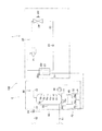
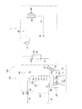
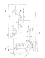
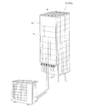
図1に、本発明の第1実施形態に係る給湯システム100の外観概略図を示す。図2に、給湯システム100の概略構成図を示す。
FIG. 1 is a schematic external view of a hot
(2)全体構成
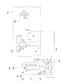
給湯システム100は、使用される前に予め温水を溜めておいたり浴槽の温水を加熱したりするための貯湯式給湯システムであって、ヒートポンプユニット1、貯湯ユニット3、および、温度調節回路40を備えている。このほか、給湯システム100は、ヒートポンプユニット1や貯湯ユニット3等の管理や制御を行うマイコンからなる図示しない制御部を備えている。
(2) Overall configuration The hot
(3)詳細構成
(3−1)ヒートポンプユニット1
ヒートポンプユニット1は、温水を作り出すための熱源装置として機能し、電力を動力源とする。ヒートポンプユニット1は、ケーシング1aを備え、当該ケーシング1a内には、冷媒が循環する冷媒回路20、水熱交換器22、空気熱交ファン24F、および、各種センサ等を備えている。
(3) Detailed configuration (3-1)
The
この冷媒回路20は、ヒートポンプとして働き、主に、圧縮機21、水熱交換器22内の冷媒管22r、膨張弁23、空気熱交換器24、および、冷媒配管25を有している。
The
冷媒配管25は、圧縮機21の吐出側、水熱交換器22内の冷媒管22r、膨張弁23、空気熱交換器24、圧縮機21の吸入側、の順に各機器を接続しており、内部に冷媒を循環させている。なお、特に限定されるものではないが、本実施形態では、二酸化炭素冷媒が、冷凍サイクルにおいて一時的に超臨界状態となるように用いられている。
The
ここで、圧縮機21は、ガス状の低圧冷媒を吸入し、高圧に圧縮して吐出する。
Here, the
水熱交換器22は、冷媒の熱を放熱する放熱器としての役割を果たす。水熱交換器22は、冷媒管22rおよび水管32wを有している。水熱交換器22は、ヒートポンプユニット1の圧縮機21によって吐出された後に冷媒管22rを流れる高温の冷媒と、後述する貯湯ユニット3を循環する際に水管32wを流れる水の間で熱交換を行わせる。この水熱交換器22における熱交換によって、冷媒管22rを通過する冷媒が冷却されると同時に、水管32wを通過する水が加熱され、温水(お湯)を作り出すことができる。ここで、温水とは、後述する貯湯タンク35に供給される市水が加熱された水であって、市水の温度よりも少なくとも1℃高い温度の水をいうものとする。
The
膨張弁23は、水熱交換器22の冷媒管22rを通過して放熱した冷媒を通過させる際に、冷媒の圧力を減少させる。
The
空気熱交換器24は、冷媒を加熱して蒸発させる蒸発器として働く。空気熱交換器24では、冷媒と空気との間で熱交換が行われる。熱交換のための空気は、空気熱交ファン24Fによって空気熱交換器24に向けて供給される。空気熱交ファン24Fは、制御部によって、制御される。
The
(3−2)貯湯ユニット3
貯湯ユニット3は、市水等の外部からの外部給水路81およびタンク用給水路82を介して供給される水をヒートポンプユニット1から得られる熱によって加熱し、蓄えつつ、混合用給水路83を介して混合された温水を浴室等に供給するための装置である。この貯湯ユニット3は、ケーシング3aを備え、当該ケーシング3a内には、主に、貯湯タンク35、貯湯回路30、蓄電池71、インバータ73、コンバータ74、スイッチング素子収納部72、および、温度調節ジャケット48等を備えている。
(3-2) Hot
The hot
(3−2−1)貯湯タンク35
貯湯タンク35は、ヒートポンプユニット1から得られる熱によって得られる温水を予め蓄えておくタンクである。
(3-2-1) Hot
The hot
貯湯タンク35内は水および/または温水によって常に満たされており、温水の量を制御部に把握させるための、湯量温度検知センサ36が設けられている。この湯量温度検知センサ36は、第1湯量検知温度センサT1〜第6湯量検知温度センサT6を有している。これらの第1湯量検知温度センサT1〜第6湯量検知温度センサT6は、貯湯タンク35の下方から上方に向けて順に所定間隔で配置されている。
The hot
貯湯タンク35内の温水の温度分布は、上端から下端に下がるにつれて温度が低くなるようになっている。これは、温度の低い温水は、比重が大きいために下に沈み、温度の高い温水は比重が小さいために上昇する傾向にあるからである。貯湯タンク35の下端では、後述するように、未加熱の水が市水として導入されるため、貯湯タンク35内のうち最も温度が低くなっている。
The temperature distribution of the hot water in the hot
貯湯タンク35の下端部近傍には、タンク用給水路82が接続されている。市水等の外部からの水が外部給水路81およびタンク用給水路82を介して貯湯タンク35内に供給される。貯湯タンク35の上端部近傍には、出湯管51が接続されている。出湯管51を介して供給される温水と混合用給水路83を介して供給される市水等の外部からの水とが湯水混合弁84により混合される。このように混合された温水は、給湯管52を介して浴室等に供給される。
A tank
なお、図示されていないが、貯湯タンク35は、発泡スチロールもしくは発泡ポリエチレン等によって形成された断熱材によって下端を除く周囲が覆われており、貯湯タンク35内の熱が逃げ出しにくいように構成されている。
Although not shown, the hot
(3−2−2)貯湯回路30
貯湯回路30は、貯湯タンク35内の水または温水に対してヒートポンプユニット1で得られる熱を伝えるための回路であり、沸き上げ往き管31、水熱交換器22内の水管32w、沸き上げ戻り管33、および、沸き上げポンプ34を有している。
(3-2-2) Hot
The hot
沸き上げ往き管31は、貯湯タンク35の下端部近傍と水熱交換器22内の水管32wの上流側端部とを接続している。
The boiling forward
沸き上げ戻り管33は、水熱交換器22内の水管32wの下流側端部と貯湯タンク35の上端近傍とを接続している。
The boiling
沸き上げポンプ34は、沸き上げ往き管31の途中に設けられている。貯湯回路30では、沸き上げポンプ34が制御部からの指令を受けて駆動することにより、貯湯タンク35内の水または温水のうち下方に存在している温度の低い水を、沸き上げ往き管31に流出させ、水熱交換器22内の水管32wを通過させることで温度上昇させ、沸き上げ戻り管33を介して貯湯タンク35の上端近傍に戻している。
The boiling
これにより、貯湯タンク35内の温水と水との境界が上から下に向けて移動していくことになり、貯湯タンク35内の温水の量が増えていく。
As a result, the boundary between the hot water and the water in the hot
(3−2−3)蓄電池71
蓄電池71は、給湯システム100によって使用される電気を貯める電池であり、貯湯タンク35の下端に熱的に接触した状態で貯湯タンク35の下に設置されている。蓄電池71は、電気料金が比較的安価な夜間に充電され、充電された電気は、日中に給湯システム100の稼働に使用される。蓄電池71は、本実施形態においてはリチウムイオン電池である。なお、蓄電池71は、蓄電池71の内部温度を検知する温度センサ71aが内蔵されている。制御部は、当該温度センサ71aの検知値を把握することができる。
(3-2-3)
The
ここで、蓄電池71の上面は、貯湯タンク35の下面と熱的に接触している。熱的に接触している状態とは、直接的に接触している状態と、他の部材が介在して間接的に接触している場合の両方が含まれる(以下同じ。)。本実施形態においては、貯湯タンク35の下端と蓄電池71の上面とは、直接的に接触している。
Here, the upper surface of the
現状の蓄電池は適切な動作が可能な温度範囲に制約があり、温度上昇とともに電池容量が劣化するため、電池の設置場所の条件が厳しく、寿命を延ばすためには一定の温度を保つ事が重要な条件となる。 Current storage batteries have restrictions on the temperature range in which they can operate properly, and the battery capacity deteriorates as the temperature rises. Therefore, the conditions of the battery installation location are severe, and it is important to maintain a constant temperature in order to extend the service life. It becomes a condition.
一方、貯湯タンク35の下端近傍には、市水からの水が導入されるので、未加熱の水が存在しており、年間を通じて市水の温度は比較的安定している。
On the other hand, since water from city water is introduced near the lower end of the hot
したがって、蓄電池71を、貯湯タンク35の下端に対して熱的に接触させることができるように貯湯タンク35の下に配置することで、一年を通じて蓄電池71の温度を比較的安定的に維持することが可能になっている。
Therefore, by arranging the
(3−2−4)温度調節ジャケット48
温度調節ジャケット48は、主に蓄電池71の温度を調節するための装置であり、蓄電池71の下端に熱的に接触した状態で蓄電池71の下に設置されている。温度調節ジャケット48の下には、スイッチング素子収納部72が設置されており、温度調節ジャケット48の下方部分とスイッチング素子収納部72の上方部分とは熱的に接触している(本実施形態では、直接的に接触している。)。温度調節ジャケット48は、アルミ等の熱伝導率の高い金属によって構成されている。したがって、蓄電池71およびスイッチング素子収納部72に収納されているインバータ73のスイッチング素子73aやコンバータ74のスイッチング素子74aを、温度調節ジャケット48の冷熱によって効率的に冷却させることが可能になっている。
(3-2-4)
The
(3−2−5)インバータ73
インバータ73は、用途は特に限定されないが、本実施形態においては、圧縮機21の周波数制御を行うインバータとして用いられている。本実施形態においては、インバータ73は、貯湯タンク35や蓄電池71や温度調節ジャケット48よりも下方に配置されており、インバータ73から熱を放出するための放熱部を有している。
(3-2-5)
The use of the
(3−2−6)コンバータ74
コンバータ74は、用途は特に限定されないが、本実施形態においては、蓄電池71の充電と放電の制御を行なうコンバータとして用いられている。本実施形態においては、コンバータ74は、貯湯タンク35や蓄電池71や温度調節ジャケット48よりも下方に配置されており、コンバータ74から熱を放出するための放熱部を有している。
(3-2-6)
The application of the
(3−2−7)スイッチング素子収納部72
スイッチング素子収納部72は、ヒートポンプユニット1が有するインバータ73のスイッチング素子73a、および、コンバータ74のスイッチング素子74aを収納している。なお、スイッチング素子収納部72の内部は、熱伝導率の高いアルミ等の金属によって構成されており、スイッチング素子収納部72に収納されているインバータ73のスイッチング素子73aやコンバータ74のスイッチング素子74aに対してスイッチング素子収納部72の外部の熱が伝わりやすいように構成されている。
(3-2-7) Switching
The switching
インバータ73のスイッチング素子73aやコンバータ74のスイッチング素子74aは稼働中に熱を帯びるようになる。これに対して、スイッチング素子73a、74aを収納しているスイッチング素子収納部72には、温度調節ジャケット48の下方部分が熱的に接触している。具体的には、インバータ73のスイッチング素子73aの放熱部側の部分やコンバータ74のスイッチング素子74aの放熱部側の部分が、温度調節ジャケット48の下方部分と接している。このため、インバータ73のスイッチング素子73aの温度や、コンバータ74のスイッチング素子74aの温度について、温度変化度合いが小さくなるように緩和させることができている。
The switching
(3−3)温度調節回路40
本実施形態では、上述した貯湯回路30の一部が温度調節回路40となっている。すなわち、貯湯回路30の一部が、蓄電池71やスイッチング素子収納部72の温度調節回路としての役割も果たしている。
(3-3)
In the present embodiment, a part of the hot
具体的には、沸き上げ往き管31は、貯湯タンク35の下端部近傍から伸び出しており、温度調節ジャケット48の内部を通過して、水熱交換器22内の水管32wの上流側端部に接続されている。このため、貯湯タンク35内の下方に存在している水は、貯湯タンク35下方から沸き上げ往き管31に流出する。沸き上げ往き管31は、温度調節ジャケット48の内部を通過した後、水熱交換器22に接続されている。このため、温度調節ジャケット48に内部を通過した水の冷熱は、蓄電池71に対して下方から伝熱され、蓄電池71の温度を調節することができる。なお、温度調節ジャケット48の内部を通過した水の熱は、冷熱に限られない。例えば、冬季の早朝のように、気温が零下となった場合であっても沸き上げ往き管31内を通過する水の温度は零下にはならないため、温度調節ジャケット48に内部を通過した水の熱によって、蓄電池71を下方から暖めることが可能になり、蓄電池71の温度を、動作温度範囲の下限を下回らないように高めることができる。
Specifically, the boiling forward
(4)全体動作
次に、給湯システム100の動作について説明する。
(4) Overall Operation Next, the operation of the hot
沸き上げポンプ34が制御部からの指令を受けて駆動すると、貯湯タンク35内の水または温水のうち下方に存在している温度の低い水が、沸き上げ往き管31に流出する。沸き上げ往き管31の中を流れる水は、温度調節ジャケット48の中を通って水熱交換器22に到達する。水熱交換器22内では、沸き上げ往き管31の中を流れる水と、ヒートポンプユニット1の高温冷媒の間で熱交換が行われる。これにより、水が加熱され温水となる。温水は、沸き上げ戻り管33を介して貯湯タンク35の上端近傍に戻る。
When the boiling
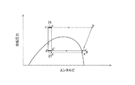
一方、冷媒回路20においては、図3のモリエル線図に示すように、圧縮機21に吸入された冷媒(図3の点a参照)は、圧縮機21により圧縮され高温高圧となり(図3の点b参照)、冷媒配管25を流れて水熱交換器22内の冷媒管22r内を通過する際に、沸き上げ往き管31を通過して流れてきた水と熱交換を行って、放熱する(図3の点c参照)。放熱後の冷媒は、膨張弁23を通過することで減圧され、低温かつ気液二相状態となる(図3の点d参照)。低温低圧になった気液二相状態の冷媒は、空気熱交換器24へ流れ、空気熱交換器24において外気との間で熱交換を行って蒸発する(図3の点a参照)。気化した冷媒は、圧縮機21に吸入され、再び、圧縮されて、高温高圧の冷媒となり、上記サイクルを繰り返す。
On the other hand, in the
貯湯タンク35から温水を浴室等に供給する場合は、貯湯タンク35の上端近傍に存在する温水が当該上端近傍に接続されている出湯管51から流出する。出湯管51を介して供給される温水と混合用給水路83を介して供給される市水等の外部からの水は、湯水混合弁84により混合される。このように混合された温水が、給湯管52を介して浴室等に供給される。
When hot water is supplied from the hot
(5)第1実施形態の特徴
(5−1)
給湯システム100において利用されている蓄電池71は、その寿命が設置されている場所の温度環境に依存し、動作温度範囲内に温度が保たれることで寿命を延ばすことができる性質を有している。
(5) Features of the first embodiment (5-1)
The
ここで、第1実施形態の給湯システム100では、蓄電池71の上方部分が貯湯タンク35の下方部分に対して熱的に接触する配置構成が採用されている。そして、貯湯タンク35の下方に貯められる水の温度範囲は、一年を通じて、蓄電池71の動作温度範囲とほぼ同じ温度範囲に維持される。このため、単に、蓄電池71の配置を上記配置にするだけで、その寿命を延ばすことが可能になっている。
Here, in the hot
なお、例えば、蓄電池71がリチウムイオン電池の場合には、放電深度が50%では温度上昇を10℃抑えることにより、他の条件下に比べて電池寿命を最低2倍延長でき、温度を25℃前後に保つ事で電池の寿命を飛躍的に向上させることができる。
For example, when the
(5−2)
第1実施形態の給湯システム100は、蓄電池71の下方部分は、温度調節ジャケット48の上方部分と熱的に接触するように配置されている。温度調節ジャケット48には貯湯タンク35の下方から水熱交換器22へ向かう温度の安定した水が流れており、蓄電池71に対して下方から伝熱することで、蓄電池71の温度を調節する。このため、蓄電池71は、その上方を貯湯タンク35の下方部分によって、下方を温度調節ジャケット48の上方部分によって、上下から挟み込まれており、上方部分からだけでなく下方部分からも、蓄電池71の温度を調節することが可能になっている。
(5-2)
In the hot
(5−3)
第1実施形態の給湯システム100では、インバータ73のスイッチング素子73aおよびコンバータ74のスイッチング素子74aが収納されたスイッチング素子収納部72は、温度調節ジャケット48の下方部分に対して熱的に接触するように配置されている。これにより、温度調節ジャケット48のうち、蓄電池71の温度調節に直接は利用されていない下方部分を、インバータ73のスイッチング素子73aやコンバータ74のスイッチング素子74aの温度調節に利用することが可能になっている。
(5-3)
In the hot
(5−4)
第1実施形態の給湯システム100では、貯湯回路30を流れる水は、水熱交換器22の水管32wに流入する前に、温度調節ジャケット48の内部を通過している。ここで、冬季などの市水温度が低い場合には、水熱交換器22の水管32wに至る前に、温度調節ジャケット48の内部を通過する際に蓄電池71の熱によって水温を上げることができ、水熱交換器22で要求される冷媒回路20側の負荷を低減させることが可能になる。
(5-4)
In the hot
(5−5)
給湯システム100の貯湯ユニット3では、比較的重い重量物である蓄電池71が、貯湯タンク35の下方に配置されている。これにより、配置の安定化を図ること(アンカー効果を得ること)が可能になっている
(6)第2実施形態
第2実施形態に係る給湯システム200について、図面を用いて説明する。
(5-5)
In the hot
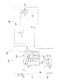
図4に、本発明の第2実施形態に係る給湯システム200の概略構成図を示す。
In FIG. 4, the schematic block diagram of the hot
(7)全体構成
給湯システム200は、上述した第1実施形態に係る給湯システム100と同様、冷媒回路220を含むヒートポンプユニット201、貯湯回路230を含む貯湯ユニット203、および、温度調節回路240を備えている。給湯システム200は、給湯システム100とほぼ同様の構成をしているので、給湯システム100と同じ構成をしている部分については説明を省略する。以下では、給湯システム100と異なる構成となっている部分を中心に説明する。
(7) Overall Configuration The hot
(8)詳細構成
(8−1)ヒートポンプユニット201
ヒートポンプユニット201は、給湯システム100のヒートポンプユニット1と異なり、水熱交換器22を備えていない。
(8) Detailed configuration (8-1)
Unlike the
(8−2)貯湯ユニット203
上記第1実施形態の水熱交換器22に対応する水熱交換器222は、貯湯ユニット203が備えている。これにより、貯湯ユニット203は、貯湯タンク35と蓄電池71と温度調節ジャケット48と水熱交換器222を一体化させるように内部に収納している。
(8-2) Hot
The hot
また、沸き上げ往き管231は、貯湯タンク35の下端部近傍から、温度調節ジャケット48を通らずに、直接、水熱交換器222に接続されている。
The boiling forward
(8−3)温度調節回路40a
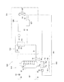
本実施形態では、冷媒回路220の一部として、温度調節回路40aが設けられている。温度調節回路40aは、蓄電池71やスイッチング素子収納部72の温度を調節するために機能する。冷媒回路220では、冷媒配管25は、圧縮機21の吐出側、水熱交換器222内の冷媒管22r、温度調節ジャケット48、膨張弁23、空気熱交換器24、圧縮機21の吸入側、の順に各機器を接続しており、内部に冷媒を循環させている。
(8-3)
In the present embodiment, a
冷媒回路220においては、水熱交換器222の冷媒管22rを通過する際に放熱した冷媒は、水熱交換器222を出て温度調節ジャケット48へ向かい、温度調節ジャケット48の内部を通過する。これにより、当該冷媒の熱が温度調節ジャケット48を介して蓄電池71およびスイッチング素子収納部72に伝達され、蓄電池71およびスイッチング素子収納部72の温度が調節される。温度調節ジャケット48の内部を通過した冷媒は、膨張弁23へ向かって流れる。
In the
(9)全体動作
次に、給湯システム200の動作について説明する。
(9) Overall Operation Next, the operation of the hot
沸き上げポンプ34が制御部からの指令を受けて駆動すると、貯湯タンク35内の水または温水のうち下方に存在している温度の低い水が、沸き上げ往き管231に流出する。沸き上げ往き管231の中を流れる水は、水熱交換器222に到達する。水熱交換器222内では、沸き上げ往き管231の中を流れる水と、ヒートポンプユニット201の高温冷媒の間で熱交換される。これにより、水が加熱され温水となる。温水は、沸き上げ戻り管33を介して貯湯タンク35の上端近傍に戻る。
When the boiling
一方、冷媒回路220においては、圧縮機21により圧縮され高温高圧になった冷媒は、冷媒配管25を流れ、水熱交換器222内の冷媒管22rを通り、沸き上げ往き管231を通って流れてきた水と熱交換し、放熱する。水熱交換器222の冷媒管22rを通過した冷媒は、温度調節ジャケット48の内部に送られる。温度調節ジャケット48の内部を通過した冷媒の熱は、蓄電池71やスイッチング素子収納部72に対して伝熱する。温度調節ジャケット48の内部を通過した冷媒は、膨張弁23を通過する際に減圧され、低温かつ気液二相状態となる。低温低圧になった気液二相状態の冷媒は、空気熱交換器24へ流れ、空気熱交換器24において外気との間で熱交換し、蒸発する。気化した冷媒は、圧縮機21に吸入され、再び圧縮され、高温高圧の冷媒となる。以下、上記動作が繰り返される。
On the other hand, in the
(10)第2実施形態の特徴
第2実施形態の給湯システム200では、上記第1実施形態と同様に、蓄電池71が貯湯タンク35と温度調節ジャケット48によって上下から挟み込まれていることで、蓄電池71の温度を調節することができている。
(10) Features of the Second Embodiment In the hot
また、第2実施形態の給湯システム200では、温度調節回路40aが設けられていることで、水熱交換器222の出口から空気熱交換器24に向かう冷媒の熱を、蓄電池71の温度調節に直接的に利用することができている。なお、ここでは、冷媒回路220における冷媒の流れを利用して温度調節ジャケット48を通過させることができているため、温度調節ジャケット48に冷媒を流す目的で設けられるような特別なポンプ等は必要無い。
In the hot
特に、第2実施形態の給湯システム200の冷媒回路220では、第1実施形態とは異なり、沸き上げ往き管231は温度調節ジャケット48の内部を通過することなく水熱交換器222の水管32wまで送られている。このため、水熱交換器222の水管32wの入口を通過する水の温度は、第1実施形態の場合と比較して、蓄電池71の熱による影響を受けていない。これにより、水熱交換器222の水管32wの入口を流れる水の温度は、蓄電池71の熱による影響を受けていない温度となるため、水熱交換器222の冷媒管22rの出口を流れる冷媒は、第1実施形態の場合とは異なる温度となる。
In particular, in the
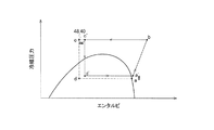
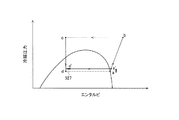
例えば、夏期について、図5のモリエル線図を参照しつつ、冷媒回路220の動作を説明すると、以下のようになる。なお、モリエル線図において、a−b−c−dで示すサイクルは、第1実施形態の場合の冷媒の挙動を示しており、第2実施形態の場合の冷媒の挙動であるa’−b−c’−d’で示すサイクルと比較するために示している。まず、水熱交換器222の冷媒管22rを通過して放熱した冷媒(図5の点c参照)は、温度調節ジャケット48の内部を通過する際に蓄電池71からの熱を受けて温度が上昇する(図5の点c’参照)。そして、温度調節ジャケット48の内部を通過した冷媒は、膨張弁23において減圧された後(図5の点d’参照)、空気熱交換器24に流入する。空気熱交換器24に流入した冷媒は、外気との間で熱交換し、蒸発する(図5の点a’参照)。なお、ここで、水熱交換器222を通過した冷媒が温度調節ジャケット48の通過時に蓄電池71からの熱を得ることにより、空気熱交換器24における冷媒の蒸発負荷を小さくすることができている。これにより、蒸発圧力および蒸発温度を上昇させることができ、COPを向上させることができる。なお、沸き上げ往き管231が温度調節ジャケット48の内部を通過していないため、水熱交換器222の冷媒管22rの出口を流れる冷媒温度は、上記第1実施形態の水熱交換器22と比較して、低温になる。しかし、蓄電池71において熱を得ることができるため、上述のようにCOPを向上させることが可能になっている。
For example, for the summer season, the operation of the
(11)第2実施形態の変形例
(11−1)変形例2A
上記第2実施形態においては、水熱交換器222から膨張弁23へ向かう冷媒が、温度調節ジャケット48の内部を通過し、沸き上げ往き管231を流れる水が温度調節ジャケット48の内部を通過しない場合を例に挙げて説明した。
(11) Modification of the second embodiment (11-1) Modification 2A
In the second embodiment, the refrigerant from the
これに対して、給湯システムとしては、例えば、図6に示すように、貯湯タンク35内の下方に存在している温度の低い水が、水熱交換器222の水管32wに到達する前に温度調節ジャケット48の内部を通過するように、第1実施形態の温度調節回路40と同様の構成をさらに備えた給湯システム200Aであってもよい。
On the other hand, as shown in FIG. 6, for example, as shown in FIG. 6, the hot water supply system has a low temperature before the low temperature water existing in the hot
なお、温度調節ジャケット48の内部では、沸き上げ往き管31のうち温度調節回路40を流れる水の流れ方向と、冷媒回路220のうち温度調節回路40aを流れる冷媒の流れ方向とは、対向流の関係となるように構成されている。
In the
この給湯システム200Aの冷媒回路220では、二酸化炭素冷媒が使用されている。水熱交換器222へ入る水の温度は、年間を通じて平準化されるため、結果的に水熱交換器222を出た冷媒の温度も平準化される。その結果、温度調節ジャケット48の温度、即ち蓄電池71の温度の平準化が可能となる。
Carbon dioxide refrigerant is used in the
なお、例えば、設置環境や使用時期によっては、図7のモリエル線図に示すように、冷媒回路220のうち水熱交換器222を流れ出た冷媒は、温度調節ジャケット48の内部を通過することで、蓄電池71からの熱を受けて加熱されるとともに、さらに、温度調節回路40aを流れる水からの熱を受けて加熱されることもある。この場合には、空気熱交換器24での蒸発負荷をさらに小さく抑えて、サイクルのCOPを向上させることが可能になる。なお、図7のモリエル線図において、a−b−c−dで示すサイクルは、第1実施形態の場合の冷媒の挙動を示しており、第2実施形態の変形例2Aの場合の冷媒の挙動であるa’−b−c’−d’で示すサイクルと比較するために示している。
For example, depending on the installation environment and use time, as shown in the Mollier diagram of FIG. 7, the refrigerant flowing out of the
なお、本変形例2Aの温度調節ジャケット48の内部では、沸き上げ往き管31のうち温度調節回路40において水が流れており、冷媒回路220のうち温度調節回路40aを冷媒が流れているため、温度調節ジャケット48の内部に二種類の流体(ハイブリッド)を流すことができている。このため、互いに熱容量の異なる水と冷媒を用いて温度調節ジャケット48の温度を調節することができるため、温度調節ジャケット48の温度をより細やかに調節することができ、結果的に、蓄電池71の温度をより細やかに調節することが可能になっている。
In addition, in the inside of the
(11−2)変形例2B
また、給湯システムとしては、例えば、上記変形例2Aの給湯システム200Aの構成に対して、さらに、バイパス回路29、主回路部分28、分岐弁28a、膨張弁28b、および、逆止弁28cを有する冷媒回路220Bを備えた、図8に示すような給湯システム200Bであってもよい。
(11-2) Modification 2B
The hot water supply system further includes, for example, a
この冷媒回路220Bは、温度調節回路40aのうち、温度調節ジャケット48の上流側と下流側とをバイパスするように接続するバイパス回路29が形成されている。なお、冷媒回路220Bのうちバイパス回路29によってバイパスされる温度調節ジャケット48側の部分を、主回路部分28とする。ここで、分岐弁28aは、水熱交換器222の冷媒管22rを通過した冷媒を、バイパス回路29側に流す状態と主回路部分28の温度調節ジャケット48側に流す状態に切り換えることができるように設けられている。膨張弁28bは、主回路部分28において、分岐弁28aから温度調節ジャケット48に向けて流れる冷媒の流量を調節することができるように設けられている。逆止弁28cは、主回路部分28において、温度調節ジャケット48を通過した冷媒が、バイパス回路29の下流側端部において合流する流れのみを許容するように設けられている。
In the
ここでは、温度調節ジャケット48へ向かう主回路部分28の途中に膨張弁28bが設けられ、温度調節ジャケット48へ向かう冷媒の流量や圧力が調整されるため、温度調節ジャケット48へ向かう冷媒の温度を、1年を通じてより安定した温度に維持することが可能になっている。
Here, the
また、水熱交換器222に入る水は、温度調節ジャケット48を通過したことで加熱されているため、水熱交換器222において水温を上げるために冷媒側に要求される熱量が低減され、消費電力を低く抑えることができる。
Further, since the water entering the
なお、分岐弁28aがバイパス回路29ではなく温度調節ジャケット48側に冷媒を流す切換状態である場合には、図9のモリエル線図に示すように、膨張弁23は全開状態となり、膨張弁28bによって冷媒回路220の低圧が制御される。ここで、例えば、夏期においては、温度調節ジャケット48を流れる冷媒は、蓄電池71の熱によって暖められるため、冷媒回路220における空気熱交換器24における冷媒の蒸発負荷を小さくすることができている。これにより、蒸発圧力および蒸発温度を上昇させることができ(図9のモリエル線図における点a’および点d’参照)、COPを向上させることができる。なお、図9のモリエル線図において、a−b−c−dで示すサイクルは、第1実施形態の場合の冷媒の挙動を示しており、第2実施形態の変形例2Bの場合の冷媒の挙動であるa’−b−c−d’で示すサイクルと比較するために示している。
When the
また、このように分岐弁28aがバイパス回路29ではなく温度調節ジャケット48側に冷媒を流す切換状態である場合には、温度調節ジャケット48を流れる冷媒の圧力を膨張弁28bによって低圧に制御することが可能となり、給湯負荷が小さい場合においても蓄電池71の温度を一定に維持しながら運転することが可能になっている。
In addition, when the
なお、本変形例2Bの温度調節ジャケット48の内部では、沸き上げ往き管31のうち温度調節回路40において水が流れており、冷媒回路220Bの主回路部分28のうち温度調節回路40aを冷媒が流れているため、温度調節ジャケット48の内部に二種類の流体(ハイブリッド)を流すことができている。このため、互いに熱容量の異なる水と冷媒を用いて温度調節ジャケット48の温度を調節することができるため、温度調節ジャケット48の温度をより細やかに調節することができ、結果的に、蓄電池71の温度をより細やかに調節することが可能になっている。
In addition, in the
(12)第3実施形態
第3実施形態に係る給湯システム300について、図面を用いて説明する。
(12) Third Embodiment A hot
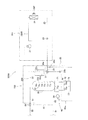
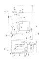
図10に、本発明の第3実施形態に係る給湯システム300の概略構成図を示す。
In FIG. 10, the schematic block diagram of the hot
(13)全体構成
給湯システム300は、本発明の第1実施形態に係る給湯システム100と同様、冷媒回路320を含むヒートポンプユニット301、貯湯回路330を含む貯湯ユニット303、および、温度調節回路40bを備えている。給湯システム300は、給湯システム100とほぼ同様の構成をしているので、給湯システム100と同じ構成をしている部分については説明を省略する。以下では、給湯システム100と異なる構成となっている部分について説明する。
(13) Overall Configuration The hot
(14)詳細構成
(14−1)ヒートポンプユニット301
ヒートポンプユニット301は、後述する温度調節回路40bが有する高温側熱交換器26、および、低温側熱交換器27を備えている。
(14) Detailed configuration (14-1)
The
即ち、冷媒回路320では、冷媒配管25は、圧縮機21の吐出側、水熱交換器22内の冷媒管22r、高温側熱交換器26、膨張弁23、低温側熱交換器27、空気熱交換器24、圧縮機21の吸入側、の順に各機器を接続しており、内部に冷媒を循環させている。
That is, in the
(14−2)温度調節回路40b
温度調節回路40bは、主に、蓄電池71およびスイッチング素子収納部72の温度を調節するための回路である。この温度調節回路40bにおいて循環する熱媒体は、特に限定されるものではないが、本実施形態では水である。本実施形態の温度調節回路40bは、ポンプ45、下流側水配管41、分岐弁46、低温側水配管42、高温側水配管43、混合弁47、上流側水配管44、高温側熱交換器26、および、低温側熱交換器27を有している。
(14-2)
The
下流側水配管41は、ポンプ45の吐出側と分岐弁46を接続し、ポンプ45により吐出された水を分岐弁46へと流す。分岐弁46に到達した水は、分岐弁46により低温側水配管42および高温側水配管43の二つに分岐される。低温側水配管42は、低温側熱交換器27の内部を通過するように伸びて、混合弁47に接続されている。高温側水配管43は、高温側熱交換器26の内部を通過するように伸びて、混合弁47に接続されている。
The
高温側熱交換器26は、水熱交換器22の出口から膨張弁23へ向かう冷媒回路320の冷媒と高温側水配管43を流れる水の間で熱交換させる。一方、低温側熱交換器27は、膨張弁23から空気熱交換器24へ向かう冷媒回路320の冷媒と低温側水配管42を流れる水の間で熱交換させる。したがって、低温側熱交換器27を出た低温側水配管42を流れる水の方が、高温側熱交換器26を出た高温側水配管43を流れる水よりも温度が低い。
The high temperature
混合弁47では、低温側水配管42の水と高温側水配管43の水が混合される。混合された水は、上流側水配管44を介して温度調節ジャケット48の内部を通過して、ポンプ45の吸入側に入る。低温側水配管42には、温度センサ42Tが設けられている。高温側水配管43には、温度センサ43Tが設けられている。上流側水配管44には、温度センサ44Tが設けられている。制御部は、温度センサ42T、温度センサ43T、および、温度センサ44Tから水の温度値を取得するとともに、蓄電池71の温度センサ71aの温度値を取得して、これらの値を基に混合弁47を制御して、低温側水配管42からの水と高温側水配管43からの水の混合比率を調節することにより、上流側水配管44内を温度調節ジャケット48に向けて流れる水の温度を調節することができるようになっている。
In the mixing
温度調節ジャケット48では、上流側水配管44を流れる水の熱は、温度調節ジャケット48を介して、蓄電池71やスイッチング素子収納部72に伝熱される。
In the
ここでは、水熱交換器22の出口から膨張弁23に向けて流れる冷媒の熱と、膨張弁23から空気熱交換器24へ向けて流れる冷媒の熱を利用することで、温度調節回路40bに送られる水の温度を調節し、蓄電池71の温度を調節することができる。また、低温側水配管42および高温側水配管43のそれぞれを流れる循環水の量が、混合弁47によって制御されている。これにより、温度調節ジャケット48に送られる水の温度が、年間を通じて最適な温度に維持されるように調節することが可能となっている。
Here, the heat of the refrigerant flowing from the outlet of the
(15)全体動作
給湯システム300の温水生成の動作は、水熱交換器22の配置が異なる点を除けば上記第2実施形態の給湯システム200と同様であるので、説明を省略する。以下に、冷媒回路320の動作を説明する。
(15) Overall operation The operation of generating hot water of the hot
冷媒回路320においては、圧縮機21により圧縮され高温高圧になった冷媒は、冷媒配管25を流れ、水熱交換器22内を通り、沸き上げ往き管31を通って流れてきた水と熱交換し、放熱する。放熱した冷媒は、減圧されることなく高温側熱交換器26を通過し、温度調節回路40bの高温側水配管43を流れる水と熱交換し、さらに放熱する。その後、冷媒は、膨張弁23により減圧され、低温かつ気液二相状態となる。低温低圧になった気液二相状態の冷媒は、低温側熱交換器27を通過し、温度調節回路40bの低温側水配管42を流れる水と熱交換し、水からの熱を得て加熱される。その後、冷媒は、空気熱交換器24へ流れ、空気熱交換器24に送られる外気との間で熱交換を行って、蒸発する。気化した冷媒は、圧縮機21に吸入され、圧縮される。圧縮された冷媒は、高温高圧の冷媒となって、上記冷凍サイクルを繰り返す。
In the
(16)第3実施形態の特徴
第3実施形態では、混合弁47における混合比率が調整されることで、高温側熱交換器26において水熱交換器22の出口から膨張弁23へ向かう冷媒の熱を利用して高温になった水、および、低温側熱交換器27において膨張弁23から空気熱交換器24へ向かう冷媒の熱を利用して低温となった水の混合比率が調整され、温度調整された水を得ることができる。このように温度調節された水は、上流側水配管44を介して温度調節ジャケット48に送られることで、蓄電池71の温度を調節することができている。これにより、冷却水の温度を、年間を通じて最適な温度に制御することが可能となっている。特に、温度調節回路40bでは、高温側熱交換器26の冷媒温度と低温側熱交換器27の冷媒温度の2つの異なる温度部分を利用することで、蓄電池71の温度をきめ細かく調節することが可能になっている。
(16) Features of Third Embodiment In the third embodiment, the mixing ratio in the mixing
また、例えば、設置環境や使用時期に関して、特に、夏期に、温度調節ジャケット48を通過して蓄電池71からの熱を受けた温度調節回路40bの下流側水配管41を流れる水の温度が、高温側熱交換器26を流れる冷媒の温度より低く、低温側熱交換器27を流れる冷媒の温度よりも高い場合には、冷媒回路320を流れる冷媒について、図11のモリエル線図に示す挙動とすることができる。すなわち、冷媒回路320の水熱交換器22を流れ出た冷媒(図11の点c参照)は、高温側熱交換器26を流れる際に高温側水配管43を流れる水によって冷却される(図11の点c’参照)。その後、高温側熱交換器26を流れ出た冷媒が、膨張弁23により減圧され(図11の点d’参照)、低温側熱交換器27を流れる際に低温側水配管42を流れる水によって加熱される(図11の点d’’参照)。なお、温度調節回路40bの高温側水配管43と低温側水配管42を流れる水の流量比が混合弁47によって調節されることで、冷媒回路320において、特に夏期など水熱交換器22への流入水温が高く、給湯時のCOP低下を招く場合には、高温側熱交換器26を流れる水によって冷媒が冷却され(図11の点c→点c’)、過冷却度を大きくとることによりCOPを向上させることができる。また一方で、冬季など外気温度が低く空気熱交換器24での冷媒の蒸発温度が低くなり、給湯時のCOP低下を招く場合には、低温側熱交換器27を流れる水によって冷媒が加熱され(図11の点d’→点d’’)、蓄電池71の排熱が利用されることにより、空気熱交換器24での蒸発負荷を小さく抑えることが可能になり、COPを向上させることができる。なお、図11のモリエル線図において、a−b−c−dで示すサイクルは、第1実施形態の場合の冷媒の挙動を示しており、第3実施形態の場合の冷媒の挙動であるa’−b−c’−d’−d’’で示すサイクルと比較するために示している。また、上記モリエル線図は、一例を示すものに過ぎず、図11において、d’’は、cとdとを結ぶ線上に位置する必要はなく、これに限定されない。
Further, for example, regarding the installation environment and use period, particularly in the summer, the temperature of the water flowing through the
(17)第4実施形態
第4実施形態に係る給湯システム400について、図面を用いて説明する。
(17) Fourth Embodiment A hot
図12に、本発明の第4実施形態に係る給湯システム400の概略構成図を示す。この給湯システム400は、特に限定されるものではないが、例えば、年間を通じた水温(市水もしくは井戸水等の温度)の平均値が15℃以下である地域で用いられることが好ましい。
In FIG. 12, the schematic block diagram of the hot
(18)全体構成
給湯システム400は、本発明の第3実施形態に係る給湯システム300と同様、冷媒回路420を含むヒートポンプユニット401、貯湯回路430を含む貯湯ユニット403、および、温度調節回路40cを備えている。給湯システム400は、給湯システム300とほぼ同様の構成をしているので、給湯システム300と同じ構成をしている部分については説明を省略し、給湯システム300と異なる構成となっている部分について中心に説明する。
(18) Overall Configuration A hot
(19)詳細構成
(19−1)温度調節回路40c
温度調節回路40cは、主に、蓄電池71およびスイッチング素子収納部72の温度を調節するための回路である。この温度調節回路40cにおいて循環する熱媒体は、特に限定されるものではないが、本実施形態では水である。本実施形態の温度調節回路40cは、ポンプ45、水配管441、および、高温側熱交換器426を有している。
(19) Detailed configuration (19-1)
The
水配管441は、ポンプ45の吐出側から伸びており、高温側熱交換器426の内部を通過した後、温度調節ジャケット48の内部を通過して、ポンプ45の吸入側に接続されている。高温側熱交換器426では、冷媒回路420のうち水熱交換器22の出口から膨張弁23へ向かう冷媒と温度調節回路40cの水配管441を流れる水の間で熱交換を行わせる。
The
ここでは、水熱交換器22の出口から膨張弁23に向かう冷媒の熱を利用して、温度調節回路40cを循環する水を介して、蓄電池71の温度を調節している。
Here, the temperature of the
(20)全体動作
給湯システム400の温水生成の動作は、上記第3実施形態の給湯システム300と同様であるので、説明を省略する。以下に、冷媒回路420の動作を説明する。
(20) Overall operation The operation of generating hot water of the hot
冷媒回路420においては、圧縮機21により圧縮され高温高圧になった冷媒は、冷媒配管25を流れ、水熱交換器22の内部を通過する際に、沸き上げ往き管31を通って流れてきた水と熱交換し、放熱する。放熱した冷媒は、高温側熱交換器426を通過し、温度調節回路40cの水配管441において高温側熱交換器426の内部を流れる水と熱交換する。その後、冷媒は、膨張弁23により減圧され、低温かつ気液二相状態となる。低温低圧になった気液二相状態の冷媒は、空気熱交換器24へ流れ、空気熱交換器24において外気と熱交換を行い、蒸発する。気化した冷媒は、圧縮機21に吸入され、圧縮される。圧縮された冷媒は、高温高圧の冷媒となり、冷凍サイクルを繰り返す。
In the
(21)第4実施形態の特徴
第4実施形態では、水熱交換器22の出口から膨張弁23へ向かう冷媒の熱を利用して、温度調節回路40cを流れる水の温度を変化させ、蓄電池71の温度調節に利用することが可能になっている。これにより、給湯システム400が生成する冷熱をより効率よく利用して蓄電池71の温度調節を行い、適切な温度に保つことが可能になっている。また、蓄電池71の排熱を利用して、水熱交換器22の出口から膨張弁23へ向かう冷媒を加熱することにより、空気熱交換器24での蒸発負荷を低減することができている。
(21) Features of the fourth embodiment In the fourth embodiment, the temperature of the water flowing through the
例えば、設置環境や使用時期において、水熱交換器22の出口から膨張弁23へ向かう冷媒の温度が、温度調節ジャケット48を通過して蓄電池71からの熱を受けた温度調節回路40cの水配管441を流れる水の温度よりも低い場合には、冷媒回路420を流れる冷媒について、図13のモリエル線図に示す挙動とすることができる。すなわち、冷媒回路420の水熱交換器22を流れ出た冷媒は、高温側熱交換器426を流れる際に、水配管441を流れる水によって加熱される(図13の点c’参照)。その後、高温側熱交換器426を流れ出た冷媒は、膨張弁23で減圧された後、空気熱交換器24において外気と熱交換して蒸発する。ここで、空気熱交換器24に送られる冷媒は、高温側熱交換器426において温度調節回路40cの水配管441を流れる水によって加熱されている。これにより、空気熱交換器24での蒸発負荷を小さく抑えることが可能になり、COPを向上させることができる(図13のモリエル線図参照)。しかも、空気熱交換器24に送られる冷媒を加熱するための熱として、水配管441を流れる水を介して蓄電池71の排熱を利用することができている。なお、図13のモリエル線図において、a−b−c−dで示すサイクルは、第1実施形態の場合の冷媒の挙動を示しており、第4実施形態の場合の冷媒の挙動であるa’−b−c−c’−d’で示すサイクルと比較するために示している。
For example, the water piping of the
(22)第5実施形態
第5実施形態に係る給湯システム500について、図面を用いて説明する。
(22) Fifth Embodiment A hot
図14に、本発明の第5実施形態に係る給湯システム500の概略構成図を示す。この給湯システム500は、特に限定されるものではないが、例えば、年間を通じた水温(市水もしくは井戸水等の温度)の平均値が25℃以上である地域で用いられることが好ましい。
In FIG. 14, the schematic block diagram of the hot
(23)全体構成
給湯システム500は、本発明の第3実施形態に係る給湯システム300と同様、冷媒回路520を含むヒートポンプユニット501、貯湯回路530を含む貯湯ユニット503、および、温度調節回路40dを備えている。給湯システム500は、給湯システム300とほぼ同様の構成をしているので、給湯システム300と同じ構成をしている部分については説明を省略し、異なっている部分を中心に説明する。
(23) Overall Configuration A hot
(24)詳細構成
(24−1)温度調節回路40d
温度調節回路40dは、主に、蓄電池71およびスイッチング素子収納部72の温度を調節するための回路である。この温度調節回路40dにおいて循環する熱媒体は、特に限定されるものではないが、本実施形態では水である。本実施形態の温度調節回路40dは、ポンプ45、水配管541、および、低温側熱交換器527を有している。
(24) Detailed configuration (24-1)
The
水配管541は、ポンプ45の吐出側から伸びており、低温側熱交換器527の内部を通過した後、温度調節ジャケット48の内部を通過して、ポンプ45の吸入側に接続されている。低温側熱交換器527では、冷媒回路520のうち膨張弁23から空気熱交換器24へ向かう冷媒と温度調節回路40dの水配管541を流れる水の間で熱交換を行わせる。
The
ここでは、膨張弁23から空気熱交換器24に向かう冷媒の熱を利用して、温度調節回路40dを循環する水を介して、蓄電池71の温度を調節している。
Here, the temperature of the
(25)全体動作
給湯システム500の温水生成の動作は、上記第3実施形態の給湯システム300と同様であるので、説明を省略する。以下に、冷媒回路520の動作を説明する。
(25) Overall operation The operation of generating hot water of the hot
冷媒回路520においては、圧縮機21により圧縮され高温高圧になった冷媒は、冷媒配管25を流れ、水熱交換器22の内部を通過する際に、沸き上げ往き管31を通って流れてきた水と熱交換し、放熱する。放熱した冷媒は、膨張弁23により減圧され、低温かつ気液二相状態となる。低温低圧になった気液二相状態の冷媒は、低温側熱交換器527を通過し、温度調節回路40dの水配管541において低温側熱交換器527の内部を流れる水と熱交換する。その後、冷媒は、空気熱交換器24へ流れ、空気熱交換器24において外気と熱交換を行い、蒸発する。気化した冷媒は、圧縮機21に吸入され、圧縮される。圧縮された冷媒は、高温高圧の冷媒となり、冷凍サイクルを繰り返す。
In the
(26)第5実施形態の特徴
第5実施形態では、膨張弁23から空気熱交換器24へ向かう冷媒の熱を利用して、温度調節回路40dを流れる水の温度を変化させ、蓄電池71の温度調節に利用することが可能になっている。これにより、給湯システム500が生成する冷熱をより効率よく利用して蓄電池71の温度調節を行い、適切な温度に保つことが可能になっている。また、蓄電池71の排熱を利用して、膨張弁23から空気熱交換器24へ向かう冷媒を加熱することにより、空気熱交換器24での蒸発負荷を低減することができている。
(26) Features of Fifth Embodiment In the fifth embodiment, the temperature of the water flowing through the
例えば、設置環境や使用時期において、膨張弁23から空気熱交換器24へ向かう冷媒の温度が、温度調節ジャケット48を通過して蓄電池71からの熱を受けた温度調節回路40dの水配管541を流れる水の温度よりも低い場合には、冷媒回路520を流れる冷媒について、図15のモリエル線図に示す挙動とすることができる。すなわち、冷媒回路520の水熱交換器22を流れ出た冷媒は、低温側熱交換器527を流れる際に、水配管541を流れる水によって加熱される(図15の点d’参照)。その後、低温側熱交換器527を流れ出た冷媒は、空気熱交換器24において外気と熱交換して蒸発する。ここで、空気熱交換器24に送られる冷媒は、低温側熱交換器527おいて温度調節回路40dの水配管541を流れる水によって加熱されている。これにより、空気熱交換器24での蒸発負荷を小さく抑えることが可能になり、COPを向上させることができる(図15のモリエル線図参照)。しかも、空気熱交換器24に送られる冷媒を加熱するための熱として、水配管541を流れる水を介して蓄電池71の排熱を利用することができている。なお、図15のモリエル線図において、a−b−c−dで示すサイクルは、第1実施形態の場合の冷媒の挙動を示しており、第5実施形態の場合の冷媒の挙動であるa’−b−c−d’で示すサイクルと比較するために示している。
For example, in the installation environment or use period, the temperature of the refrigerant from the
(27)第6実施形態
第6実施形態に係る給湯システム600について、図面を用いて説明する。
(27) Sixth Embodiment A hot
図16に、本発明の第6実施形態に係る給湯システム600の概略構成図を示す。
In FIG. 16, the schematic block diagram of the hot
(28)全体構成
給湯システム600は、本発明の第1実施形態に係る給湯システム100と同様、冷媒回路20を含むヒートポンプユニット1、および、貯湯回路630を含む貯湯ユニット603を備えている。給湯システム600は、給湯システム100とほぼ同様の構成をしているので、給湯システム100と同じ構成をしている部分については説明を省略し、異なっている部分を中心に説明する。
(28) Overall Configuration The hot
(29)詳細構成
(29−1)貯湯回路630
貯湯回路630は、上記第1実施形態の貯湯回路30とは異なる。貯湯回路630の沸き上げ往き管31は、貯湯タンク35の下方から伸びており、沸き上げポンプ34を介して水熱交換器22の水管32wに接続されており、温度調節ジャケット48の内部は通過していない。
(29) Detailed configuration (29-1) Hot
The hot
(29−2)温度調節回路40e
温度調節回路40eは、主に、蓄電池71およびスイッチング素子収納部72の温度を調節するための回路である。この温度調節回路40eには、貯湯タンク35に存在している水が熱媒体として循環する。本実施形態の温度調節回路40eは、ポンプ634、および、水配管641を有している。
(29-2)
The
水配管641は、貯湯タンク35の下方から伸びており、ポンプ634および温度調節ジャケット48の内部を通過して、貯湯タンク35の下方の異なる部分に戻すように接続されている。
The
ここで、蓄電池71の上方部分は、貯湯タンク35の下面とは、直接は接触していない。温度調節ジャケット48の上方部分は、蓄電池71の下方部分に対して直接接触しており、温度調節ジャケット48の下方部分は、スイッチング素子収納部72に対して直接接触している。
Here, the upper part of the
(30)第6実施形態の特徴
第6実施形態の給湯システム600は、給湯システム100とは異なり、温度調節ジャケット48と貯湯タンク35とが直接接触していないものの、貯湯タンク35の下方の冷水を温度調節回路40eに循環させることで温度調節ジャケット48の温度を調節して、蓄電池71の温度を調節することが可能になっている。
(30) Features of the Sixth Embodiment Unlike the hot
(31)第7実施形態
第7実施形態に係る給湯システム700について、図面を用いて説明する。
(31) Seventh Embodiment A hot
図17に、本発明の第7実施形態に係る給湯システム700の概略構成図を示す。
In FIG. 17, the schematic block diagram of the hot
(32)全体構成
給湯システム700は、本発明の第1実施形態に係る給湯システム100と同様、冷媒回路20を含むヒートポンプユニット1、および、貯湯回路730を含む貯湯ユニット703を備えている。給湯システム700は、給湯システム100とほぼ同様の構成をしているので、給湯システム100と同じ構成をしている部分については説明を省略し、異なっている部分を中心に説明する。
(32) Overall Configuration The hot
(33)詳細構成
(33−1)貯湯回路730
貯湯回路730は、上記第1実施形態の貯湯回路30とは異なる。貯湯回路730の沸き上げ往き管31は、貯湯タンク35の下方から伸びており、沸き上げポンプ34を介して水熱交換器22の水管32wに接続されており、温度調節ジャケット48の内部は通過していない。
(33) Detailed configuration (33-1) Hot
The hot
(33−2)温度調節回路40f
温度調節回路40fは、主に、蓄電池71およびスイッチング素子収納部72の温度を調節するための回路である。この温度調節回路40fには、貯湯タンク35に存在している水が熱媒体として循環する。本実施形態の温度調節回路40fは、ポンプ734、および、水配管741を有している。
(33-2)
The
水配管741は、貯湯タンク35の下方から伸びており、ポンプ734および温度調節ジャケット48の内部を通過して、貯湯タンク35の下方の異なる部分に戻すように接続されている。
The
ここで、本実施形態の給湯システム700では、蓄電池71は貯湯ユニット703内に収納されているが、上記第1実施形態の給湯システム100とは異なり、蓄電池71は、温度調節ジャケット48の上方ではなく温度調節ジャケット48の下方部分に対して蓄電池71の上方部分が直接接触するように配置されている。また、スイッチング素子収納部72は、温度調節ジャケット48の上方部分に対して直接接触するように配置されている。
Here, in the hot
(34)第7実施形態の特徴
第7実施形態の給湯システム700は、給湯システム100とは異なり、温度調節ジャケット48と貯湯タンク35とが直接接触していないものの、貯湯タンク35の下方の冷水を温度調節回路40fに循環させることで温度調節ジャケット48の温度を調節して、蓄電池71の温度を調節することが可能になっている。
(34) Features of Seventh Embodiment A hot
また、スイッチング素子収納部72についても、貯湯タンク35の下方部分に対して直接接触され、かつ、温度調節ジャケット48の上方部分に対して直接接触するように配置されていることで、スイッチング素子収納部72の温度調節を行うことが可能になっている。
Further, the switching
上述のように、本実施形態の給湯システム700では、蓄電池71およびスイッチング素子収納部72の両方の温度調節が可能になっているだけでなく、蓄電池71を貯湯タンク35よりも下方であって温度調節ジャケット48よりも下方であってスイッチング素子収納部72よりも下方に配置することができている。このため、温度調節ジャケット48やスイッチング素子収納部72よりも重い蓄電池71を下方に配置させることによって、配置の安定化を図ること(アンカー効果を得ること)が可能になっている。
As described above, in the hot
(35)第8実施形態
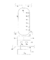
第8実施形態に係る給湯システム800について、図面を用いて説明する。
(35) Eighth Embodiment A hot
図18に、本発明の第8実施形態に係る給湯システム800の概略構成図を示す。
In FIG. 18, the schematic block diagram of the hot
(36)全体構成
給湯システム800は、本発明の第3実施形態に係る給湯システム300と同様の冷媒回路820を含むヒートポンプユニット801、および、貯湯回路830を含む貯湯ユニット803を備えている。給湯システム800は、給湯システム300とほぼ同様の構成をしているので、給湯システム300と同じ構成をしている部分については説明を省略し、異なっている部分を中心に説明する。
(36) Overall Configuration The hot
(37)詳細構成
(37−1)貯湯回路830
貯湯回路830は、上記第3実施形態の貯湯回路330とは異なる。貯湯回路830の沸き上げ往き管31は、貯湯タンク35の下方から伸びており、温度調節ジャケット48の内部を通過した後、沸き上げポンプ34を介して水熱交換器22の水管32wに接続されている。この第8実施形態の貯湯回路830は、その一部が温度調節回路40となっている。すなわち、貯湯回路830の一部が、温度調節ジャケット48の内部を通過するように構成されていることで、蓄電池71やスイッチング素子収納部72の温度調節回路としての役割も果たしている。
(37) Detailed configuration (37-1) Hot
The hot
なお、温度調節回路40gは、上述した第3実施形態に係る給湯システム300と同様である。なお、特に限定されないが、本実施形態では、温度調節回路40gの内部には水が循環している。
The
(38)第8実施形態の特徴
第8実施形態の給湯システム800は、温度調節ジャケット48の内部には、沸き上げ往き管31と温度調節回路40gの両方が通過している。このため、沸き上げ往き管31を流れる水の熱量、および、温度調節回路40gを流れている水の熱量の両方を用いて、温度調節ジャケット48の温度を調節することが可能になっている。このため、温度調節ジャケット48の内部を通過している管や回路が、沸き上げ往き管31だけの場合や温度調節回路40gだけの場合と比べて、2種類の熱によって温度調節が可能になるため、温度調節をより細やかに行うことができる。このように、温度調節ジャケット48の温度をより細やかに調節することができるため、蓄電池71の温度をより細やかに調節することが可能になっている。
(38) Features of Eighth Embodiment In the hot
(39)第9実施形態
第9実施形態に係る給湯システム900について、図面を用いて説明する。
(39) Ninth Embodiment A hot
図19に、本発明の第9実施形態に係る給湯システム900の概略構成図を示す。
In FIG. 19, the schematic block diagram of the hot
(40)全体構成
給湯システム900は、本発明の第3実施形態に係る給湯システム300と同様の冷媒回路920を含むヒートポンプユニット901、および、貯湯回路930と温度調節回路40eを含む貯湯ユニット903を備えている。給湯システム900は、給湯システム900とほぼ同様の構成をしているので、給湯システム900と同じ構成をしている部分については説明を省略し、異なっている部分を中心に説明する。
(40) Overall configuration A hot
(41)詳細構成
(41−1)温度調節回路40h
温度調節回路40hは、沸き上げ往き管31とは別に設けられた回路であって、主に、蓄電池71およびスイッチング素子収納部72の温度を調節するための回路であり、ポンプ934、および、水配管941を有している。この温度調節回路40hには、貯湯タンク35に存在している水が熱媒体として循環する。
(41) Detailed configuration (41-1)
The
水配管941は、貯湯タンク35の下方から伸びており、ポンプ934および温度調節ジャケット48の内部を通過して、貯湯タンク35の下方の異なる部分に戻すように接続されている。
The
なお、温度調節回路40gは、上述した第3実施形態に係る給湯システム300と同様である。なお、特に限定されないが、本実施形態では、温度調節回路40gの内部には水が循環している。
The
(42)第9実施形態の特徴
第9実施形態の給湯システム900は、温度調節ジャケット48の内部には、温度調節回路40hと温度調節回路40gの両方が通過している。このため、温度調節回路40hを流れる水の熱量、および、温度調節回路40gを流れている水の熱量の両方を用いて、温度調節ジャケット48の温度を調節することが可能になっている。このため、温度調節ジャケット48の内部を通過している管や回路が、温度調節回路40hだけの場合や温度調節回路40gだけの場合と比べて、2種類の熱によって温度調節が可能になるため、温度調節をより細やかに行うことができる。このように、温度調節ジャケット48の温度をより細やかに調節することができるため、蓄電池71の温度をより細やかに調節することが可能になっている。
(42) Features of Ninth Embodiment In the hot
(43)他の実施形態
上述した各実施形態は、以下に述べるように変形させて得られる実施形態としてもよい。
(43) Other Embodiments Each of the above-described embodiments may be an embodiment obtained by being modified as described below.
(43−1)他の実施形態A
上記第1〜第6実施形態および第8、第9実施形態では、貯湯タンク35の下端と蓄電池71の上方部分とが直接的に接触している場合を例に挙げて説明した。
(43-1) Other Embodiment A
In the first to sixth embodiments and the eighth and ninth embodiments, the case where the lower end of the hot
これに対して、貯湯タンク35と蓄電池71との熱的な接触態様は、特に限定されるものではなく、例えば、図20に示すように、熱伝導率の高い部材として熱伝導部材Hを貯湯タンク35と蓄電池71の間に介在させることで、両者を間接的に接触させるようにしてもよい。この熱伝導部材Hは、例えば、熱伝導率の高いアルミニウム合金製等の部材とすることができる。熱伝導部材Hは、その上端が貯湯タンク35の下端と直接接触しており、その下端が蓄電池71の上端と直接接触している。
On the other hand, the thermal contact mode between the hot
これにより、貯湯タンク35の下方部分の熱は、熱伝導部材Hを介して蓄電池71に効率良く伝達されるため、蓄電池71の温度調節を容易に行うことが可能になる。
Thereby, since the heat of the lower part of the hot
また、貯湯タンク35の下端の形状と蓄電池71の上端の形状とが対応する形状となっておらず、そのままでは隙間が生じる場合には、上述の熱伝導部材Hの形状を工夫することで、熱伝達率を向上させることができる。すなわち、熱伝導部材Hの上端の形状を貯湯タンク35の下端の形状に対応する形状としつつ、熱伝導部材Hの下端の形状を蓄電池71の上端の形状に対応する形状とすることができる。
Moreover, when the shape of the lower end of the hot
(43−2)他の実施形態B
上記他の実施形態Aでは、熱伝導部材Hを貯湯タンク35と蓄電池71の間に介在させて、両者を間接的に接触させる例を挙げて説明した。
(43-2) Other embodiment B
In the other embodiment A described above, the heat conducting member H is interposed between the hot
しかし、貯湯タンク35の下方に設けられる熱伝導部材Hの利用例は、これに限られない。
However, the usage example of the heat conducting member H provided below the hot
図21に示すように、例えば、第7実施形態の給湯システム700のように、温度調節ジャケット48の下方部分に対して蓄電池71の上方部分が直接接触するように配置され、温度調節ジャケット48の上方部分に対してスイッチング素子収納部72が直接接触するように配置され、貯湯タンク35の下方部分と蓄電池71が直接接触していない場合についても、貯湯タンク35の下方とスイッチング素子収納部72の間(本他の実施形態Bでは、具体的には、貯湯タンク35の下方と、インバータ73およびコンバータ74の間)に熱伝導部材Hを配置する用に変形してもよい。
As shown in FIG. 21, for example, like the hot
(43−3)他の実施形態C
上記各実施形態の給湯システムでは、図22に示すように、貯湯ユニット3〜703のケーシング3aの外表面に太陽光発電パネルSを取りつけられていてもよい。
(43-3) Other Embodiment C
In the hot water supply system of each of the embodiments described above, as shown in FIG. 22, the photovoltaic power generation panel S may be attached to the outer surface of the
このように太陽光発電パネルSが設けられている場合には、太陽光発電パネルSが太陽光を受光して発電した電気を、ヒートポンプユニットの駆動電力として、および/または、貯湯ユニットの駆動電力として利用してもよい。さらに、ヒートポンプユニットの駆動電力や貯湯ユニットの駆動電力として用いない場合には、蓄電池71の充電に用いてもよい。
When the solar power generation panel S is provided in this way, the electricity generated by the solar power generation panel S receiving sunlight is generated as drive power for the heat pump unit and / or drive power for the hot water storage unit. It may be used as Further, when not used as driving power for the heat pump unit or driving power for the hot water storage unit, it may be used for charging the
ここで、太陽光発電パネルSによる発電は太陽光の照射を受ける昼間に行われるため、太陽光発電パネルSによって発電された電気を蓄電池71に充電する処理も昼間に行われることになる。このため、蓄電池71は、上記充電を行って電流が流れている昼間に発熱しやすい。これに対して、蓄電池71において充電が行われている時間帯に、水および/または冷媒を温度調節ジャケット48に通過させるように運転を行ってもよい。例えば、蓄電池71において充電が行われている時間帯に、圧縮機21と沸き上げポンプ34、ポンプ45、ポンプ634、ポンプ734、ポンプ934を駆動させて沸き上げが行われるようにしてもよい。なお、ここでの沸き上げ時の温度調節ジャケット48の水および/または冷媒の通過量は、特に限定されず、温度調節ジャケット48の温度を所望の温度範囲に維持することができる程度であれば少ない通過量であってもよい。温度調節ジャケット48の水および/または冷媒の通過量の調節手法は、特に限定されないが、例えば、弁開度の調節や流量可変ポンプの出力調節によって行うことができる。なお、蓄電池71の充電が行われていることは、蓄電池71の温度が所定温度以上に上昇することを検知することで把握してもよいし、太陽光発電パネルSでの発電が行われる時間帯と同じであると仮定することで太陽光照射時間帯の情報を収集することで把握してもよい。なお、この際、太陽光発電パネルSによる発電で得られた電気は、当該発電と同時に、その一部を温度調節ジャケット48に水および/または冷媒を通過させるための運転に用いつつ、残りの電気を蓄電池71への蓄電に用いるようにしてもよい。
Here, since the power generation by the solar power generation panel S is performed in the daytime when sunlight is irradiated, the process of charging the
上述のように太陽光発電パネルSを採用した場合には、上述のように電力を利用することができるだけでなく、太陽光発電パネルSが貯湯タンク35の外周を覆うように設けられていることで、太陽光による熱エネルギーが、ケーシング3a内の温度上昇に用いられる程度を抑え、太陽光発電パネルSにより発電された電気エネルギーとして利用することができる。これにより、太陽光によってケーシング3aの内部の温度が上昇することを抑制し、蓄電池71の温度を適切な温度範囲内に維持しやすくなる。
When the solar power generation panel S is employed as described above, not only can the electric power be used as described above, but the solar power generation panel S is provided so as to cover the outer periphery of the hot
(43−4)他の実施形態D
上記実施形態では、インバータ73が圧縮機21の周波数制御を行うインバータとして用いられ、コンバータ74が蓄電池71の充電と放電の制御を行うコンバータとして用いられる場合を例に挙げて説明した。
(43-4) Other Embodiment D
In the above embodiment, the case where the
これに対して、インバータ73の用途は、圧縮機の周波数制御を行うインバータに限られず、例えば、上記他の実施形態Cで示すように、太陽光発電パネルSによる発電が行われる給湯システムにおいて、太陽光発電パネルSで得られた直流電流を処理するためにインバータ73とコンバータ74が用いられてもよい。この場合には、特に限定されないが、例えば、太陽光発電パネルSで得られた電力の電圧をコンバータ74によって調節し、直流電流をパワーコンディショナーとして機能させたインバータ73によって交流電流に変換するようにしてもよい。なお、以上のようにして処理することで得られる電気の用途は、特に限定されないが、例えば、ヒートポンプユニットにおいて用いてもよいし、貯湯ユニットにおいて用いてもよいし、他の電気機器において用いてもよい。
On the other hand, the use of the
(43−5)他の実施形態E
上記第8実施形態および第9実施形態では、温度調節ジャケット48の内部には、沸き上げ往き管31または温度調節回路40hのいずれかと、温度調節回路40gの両方が通過しており、温度調節回路40gの内部には水が循環している場合を例に挙げて説明した。すなわち、温度調節ジャケット48の内部を通過する流体がいずれも水で共通している場合を例に挙げて説明した。
(43-5) Other embodiment E
In the eighth embodiment and the ninth embodiment, either the boiling forward
これに対して、温度調節回路40gを通過する熱媒体としては、水とは熱容量の異なる流体であってもよく、例えば、エチレングリコールの水溶液、スラリーアイス、または、冷媒であってもよい。すなわち、温度調節ジャケット48は、その内部に、水と水以外の流体の互いに異なる複数種類の流体が流れるハイブリッド形態であってもよい。
On the other hand, the heat medium passing through the
このように、ハイブリッド形態を採用することにより、温度調節ジャケット48の温度をより細やかに調節することができ、結果的に蓄電池71の温度をより細やかに調節することが可能になる。また、給湯システムが設置される環境に応じて、温度調節回路40gを循環する媒体を適宜選択することにより、蓄電池71の温度調節をより適切に行うことが可能になる。
Thus, by adopting the hybrid form, the temperature of the
(43−6)他の実施形態F
上記第6実施形態の温度調節回路40e、第7実施形態の温度調節回路40f、および、第9実施形態の温度調節回路40hでは、沸き上げ往き管31とは別に設けられた回路であって、貯湯タンク35の下方から伸びてポンプ634、734、934や温度調節ジャケット48の内部を通過して貯湯タンク35の下方の異なる部分に戻す水配管641、741、941が設けられている場合を例に挙げて説明した。すなわち、水配管641、741、941の上流側端部と貯湯タンク35の接続位置および下流側端部と貯湯タンク35の接続位置が、貯湯タンク35の下方における互いに異なる位置であって高さ位置が同程度の場合を例に挙げて説明した。
(43-6) Other embodiment F
In the
これに対して、図23に示すように、水配管641、741、941の上流側端部と貯湯タンク35の接続位置P1および下流側端部と貯湯タンク35の接続位置P2は、貯湯タンク35の下方における互いに異なる位置であって高さ位置も異なる位置となっていてもよい。
On the other hand, as shown in FIG. 23, the connection position P1 between the upstream ends of the
具体的には、水配管641、741、941の下流側端部と貯湯タンク35の接続位置P2が、水配管641、741、941の上流側端部と貯湯タンク35の接続位置P1よりも高い位置であって、貯湯タンク35の下方10〜30%の高さ位置であることが好ましい。このように水配管641、741、941の下流側端部の位置を上流側端部よりも高めにすることで、温度調節ジャケット48を通過して温度上昇した水を貯湯タンク35内に戻す位置を高めにすることができる。これにより、貯湯タンク35内部の温度分布の乱れを小さく抑えることが可能になる。
Specifically, the connection position P2 between the downstream ends of the
(43−7)他の実施形態G
上記第8実施形態および第9実施形態では、互いに独立した流路を構成する複数の配管が内部を通過する温度調節ジャケット48、高温側熱交換器26、および、低温側熱交換器27が用いられた例を挙げて説明した。
(43-7) Other embodiment G
In the eighth embodiment and the ninth embodiment, the
ここで、これらの温度調節ジャケット48、高温側熱交換器26、および、低温側熱交換器27は、互いに独立した流路を構成する複数の配管が内部を通過している点で共通しているため、構造的に同じ形状および寸法が採用されていてもよい。この場合には、これらの温度調節ジャケット48、高温側熱交換器26、および、低温側熱交換器27において部品を共通化させることが可能になるため、コストを低減させることができる。
Here, the
(43−8)他の実施形態H
上記各実施形態の冷媒回路を流れる冷媒としては、特に限定されるものではなく、例えば、R32やR401A等のHFC冷媒であってもよい。
(43-8) Other embodiment H
The refrigerant flowing through the refrigerant circuit of each of the above embodiments is not particularly limited, and may be an HFC refrigerant such as R32 or R401A.
(43−9)他の実施形態I
上記各実施形態では、蓄電池71としてリチウムイオン電池が用いられる場合を例に挙げて説明したが、蓄電池71としては、これに限られず、ニッケル水素電池等、他のタイプの蓄電池でもよい。
(43-9) Other Embodiment I
In each of the above embodiments, the case where a lithium ion battery is used as the
(43−10)他の実施形態J
上記各実施形態では、蓄電池71とスイッチング素子収納部72のいずれか一方を、貯湯タンク35の下方部分と温度調節ジャケット48の上方部分とで上下から挟み込む実施形態を例に挙げて説明した。
(43-10) Other embodiment J
In each of the above embodiments, the embodiment has been described in which one of the
これに対して、蓄電池71もスイッチング素子収納部72もいずれも、貯湯タンク35の下方部分および温度調節ジャケット48の上方部分に接するように両者の間に配置された実施形態とすることもできる。
On the other hand, both the
(43−11)他の実施形態K
上記実施形態では、第3−第5実施形態のポンプ45、第6実施形態のポンプ634、第7実施形態のポンプ734の駆動タイミングについて、特に限定することなく説明したが、例えば、蓄電池71として充電時に発熱するタイプのものを採用する場合には、当該充電時を把握してポンプが駆動されるように制御部が制御を行ってもよい。この場合には、蓄電池71の充電時における発熱に伴う蓄電池71のダメージを低減させることができる。
(43-11) Other embodiment K
In the said embodiment, although the drive timing of the
(43−12)他の実施形態L
上記各実施形態は、それぞれ互い阻害する事由が無い限り、当業者に可能な範囲で、適宜各実施形態を組み合わせてもよい。
(43-12) Other embodiment L
As long as there is no reason to inhibit each other, the above embodiments may be appropriately combined with each other as long as those skilled in the art can.
本発明は、蓄電池を備えたヒートポンプ式の給湯システムに有用である。 The present invention is useful for a heat pump hot water supply system including a storage battery.
1、201、301、401、501、601、701、801、901 ヒートポンプユニット
20、220、220B、320、420、520、620、720、820、920 冷媒回路(ヒートポンプ)
22 水熱交換器(放熱器)
23 膨張弁(膨張機構)
24 空気熱交換器(蒸発器)
30、230 貯湯回路(未加熱水回路、第2未加熱水回路)
35 貯湯タンク
40 温度調節回路(第2温度調節部、第3温度調節部)
40a 温度調節回路(第1温度調節部、直接温度調節回路)
40b、40c 温度調節回路(第1温度調節部)
40d 温度調節回路(第1温度調節部、第4温度調節部、第5温度調節部)
40e 温度調節回路(第2温度調節部、第3温度調節部)
40f 温度調節回路(第2温度調節部、第3温度調節部)
40g 温度調節回路(第1温度調節部、間接温度調節回路)
40h 温度調節回路(第2温度調節部、第3温度調節部)
40j 温度調節回路(第2温度調節部)
45 ポンプ
48 温度調節ジャケット(第1温度調節部、第2温度調節部、第3温度調節部、第4温度調節部、第5温度調節部)
71 蓄電池
71a 温度センサ
72 スイッチング素子収納部
73 インバータ
73a インバータのスイッチング素子
74 コンバータ
74a コンバータのスイッチング素子
100、200、200A、200B、300、400、500、600、700、800、900 給湯システム
641 水配管(第2未加熱水回路)
741 水配管(第2未加熱水回路、第3未加熱水回路、第4未加熱水回路)
830 貯湯回路(第1未加熱水回路、第2未加熱水回路)
941 水配管(第1未加熱水回路、第2未加熱水回路)
H 熱伝導部材
S ソーラーパネル
1, 201, 301, 401, 501, 601, 701, 801, 901
22 Water heat exchanger (radiator)
23 Expansion valve (expansion mechanism)
24 Air heat exchanger (evaporator)
30, 230 Hot water storage circuit (unheated water circuit, second unheated water circuit)
35 Hot
40a Temperature control circuit (first temperature control unit, direct temperature control circuit)
40b, 40c Temperature control circuit (first temperature control unit)
40d Temperature control circuit (first temperature control unit, fourth temperature control unit, fifth temperature control unit)
40e Temperature control circuit (second temperature control unit, third temperature control unit)
40f Temperature control circuit (second temperature control unit, third temperature control unit)
40g Temperature control circuit (first temperature control unit, indirect temperature control circuit)
40h Temperature control circuit (second temperature control unit, third temperature control unit)
40j Temperature control circuit (second temperature control unit)
45
71
741 Water piping (second unheated water circuit, third unheated water circuit, fourth unheated water circuit)
830 Hot water storage circuit (first unheated water circuit, second unheated water circuit)
941 Water piping (first unheated water circuit, second unheated water circuit)
H Heat conduction member S Solar panel
Claims (16)
下方に未加熱の水が供給され、上方で前記冷媒回路のうち前記放熱器を流れる冷媒の熱を利用して生成された温水を蓄える貯湯タンク(35)と、
少なくとも前記ヒートポンプによって使用される電力を蓄電する蓄電池(71)と、
前記蓄電池の少なくとも一部に対して熱的に接触するように配置されており、前記冷媒回路のうち前記放熱器を通過した後であって前記圧縮機に吸入される前の冷媒の熱を直接的もしくは間接的に利用して、前記蓄電池の温度を調節する第1温度調節部(48、40g)と、
前記貯湯タンクの下方の未加熱の水が循環するように構成された第1未加熱水回路(830、941)と、
前記第1未加熱水回路を流れる水の熱を利用して前記蓄電池の温度を調節する第2温度調節部(48、40、40h)と、
を備え、
前記蓄電池の少なくとも一部が前記貯湯タンクの下方部分に対して熱的に接触するように配置されており、
前記第1温度調節部は、前記冷媒回路のうち前記放熱器を通過した後であって前記圧縮機に吸入される前の冷媒の熱と熱交換を行う温度調節媒体が循環しており、前記第1未加熱水回路とは独立した回路である間接温度調節回路(40g)を有している、
給湯システム(800、900)。 A heat pump ( 820, 920) including a compressor, a radiator, an expansion mechanism, an evaporator, and a refrigerant circuit in which the refrigerant circulates ;
A hot water storage tank (35) for storing hot water that is supplied with unheated water below and that stores hot water generated using heat of the refrigerant flowing through the radiator in the refrigerant circuit at the top;
A storage battery (71) for storing at least the electric power used by the heat pump;
It is arranged so as to be in thermal contact with at least a part of the storage battery, and the heat of the refrigerant after passing through the radiator in the refrigerant circuit and before being sucked into the compressor is directly A first temperature adjusting unit (48, 40 g) that adjusts the temperature of the storage battery using the target or indirectly,
A first unheated water circuit (830, 941) configured to circulate unheated water below the hot water storage tank;
A second temperature adjusting unit (48, 40, 40h) for adjusting the temperature of the storage battery using heat of water flowing through the first unheated water circuit;
With
At least a part of the storage battery is arranged so as to be in thermal contact with the lower part of the hot water storage tank ,
The first temperature adjustment unit circulates a temperature adjustment medium that performs heat exchange with heat of the refrigerant after passing through the radiator in the refrigerant circuit and before being sucked into the compressor, Having an indirect temperature control circuit (40 g) which is a circuit independent of the first unheated water circuit,
Hot water supply system (800, 900).
請求項1に記載の給湯システム(800、900)。 The temperature control medium is a heat medium other than water.
The hot water supply system (800, 900) according to claim 1 .
下方に未加熱の水が供給され、上方で前記冷媒回路のうち前記放熱器を流れる冷媒の熱を利用して生成された温水を蓄える貯湯タンク(35)と、
少なくとも前記ヒートポンプによって使用される電力を蓄電する蓄電池(71)と、
前記蓄電池の少なくとも一部に対して熱的に接触するように配置されており、前記冷媒回路のうち前記放熱器を通過した後であって前記圧縮機に吸入される前の冷媒の熱を直接的もしくは間接的に利用して、前記蓄電池の温度を調節する第1温度調節部(48、40a、40b、40c、40d、40g)と、
を備え、
前記蓄電池(71)の上方部分は、前記貯湯タンクの下方部分に対して熱的に接触しており、
前記蓄電池(71)の下方部分は、前記第1温度調節部(48、40a、40b、40c、40d、40g)に対して熱的に接触している、
給湯システム(200、200A、200B、300、400、500、800、900)。 A heat pump (20, 220 , 220B, 320 , 420, 520 , 820 , 920) including a compressor, a radiator, an expansion mechanism, an evaporator, and a refrigerant circuit in which the refrigerant circulates ;
A hot water storage tank (35) for storing hot water that is supplied with unheated water below and that stores hot water generated using heat of the refrigerant flowing through the radiator in the refrigerant circuit at the top;
A storage battery (71) for storing at least the electric power used by the heat pump;
It is arranged so as to be in thermal contact with at least a part of the storage battery, and the heat of the refrigerant after passing through the radiator in the refrigerant circuit and before being sucked into the compressor is directly A first temperature adjusting unit (48, 40a, 40b, 40c, 40d, 40g) that adjusts the temperature of the storage battery using the target or indirectly,
With
The upper part of the storage battery (71) is in thermal contact with the lower part of the hot water storage tank,
The lower part of the storage battery (71) is in thermal contact with the first temperature control part (48, 40a, 40b, 40c, 40d, 40g),
Hot water supply system (200, 200A, 200B, 300 , 400 , 500, 800 , 900).
下方に未加熱の水が供給され、上方で前記冷媒回路のうち前記放熱器を流れる冷媒の熱を利用して生成された温水を蓄える貯湯タンク(35)と、
少なくとも前記ヒートポンプによって使用される電力を蓄電する蓄電池(71)と、
前記蓄電池の少なくとも一部に対して熱的に接触するように配置されており、前記冷媒回路のうち前記放熱器を通過した後であって前記圧縮機に吸入される前の冷媒の熱を直接的もしくは間接的に利用して、前記蓄電池の温度を調節する第1温度調節部(48、40a、40b、40c、40d、40g)と、
を備え、
前記蓄電池の少なくとも一部が前記貯湯タンクの下方部分に対して熱的に接触するように配置されており、
前記ヒートポンプは、インバータ(73)をさらに有しており、
前記インバータのスイッチング素子(73a)は、前記第1温度調節部(48、40a、40b、40c、40d、40g)に対して熱的に接触するように設置されている、
給湯システム(200、200A、200B、300、400、500、800、900)。 A heat pump (20, 220, 220B, 320, 420, 520, 620, 720, 820, 920) including a compressor, a radiator, an expansion mechanism, an evaporator, and a refrigerant circuit in which the refrigerant circulates ;
A hot water storage tank (35) for storing hot water that is supplied with unheated water below and that stores hot water generated using heat of the refrigerant flowing through the radiator in the refrigerant circuit at the top;
A storage battery (71) for storing at least the electric power used by the heat pump;
It is arranged so as to be in thermal contact with at least a part of the storage battery, and the heat of the refrigerant after passing through the radiator in the refrigerant circuit and before being sucked into the compressor is directly A first temperature adjusting unit (48, 40a, 40b, 40c, 40d, 40g) that adjusts the temperature of the storage battery using the target or indirectly,
With
At least a part of the storage battery is arranged so as to be in thermal contact with the lower part of the hot water storage tank ,
The heat pump further includes an inverter (73),
The switching element (73a) of the inverter is installed so as to be in thermal contact with the first temperature control unit (48, 40a, 40b, 40c, 40d, 40g).
Hot water supply system (200, 200A, 200B, 300 , 400 , 500, 800 , 900).
請求項4に記載の給湯システム(200、200A、200B、300、400、500、800、900)。 The inverter (73) is disposed below the first temperature control unit (48, 40a, 40b, 40c, 40d , 40g),
The hot water supply system according to claim 4 (200, 200A, 200B, 300 , 400 , 500, 800 , 900).
下方に未加熱の水が供給され、上方で前記冷媒回路のうち前記放熱器を流れる冷媒の熱を利用して生成された温水を蓄える貯湯タンク(35)と、
少なくとも前記ヒートポンプによって使用される電力を蓄電する蓄電池(71)と、
前記蓄電池の少なくとも一部に対して熱的に接触するように配置されており、前記冷媒回路のうち前記放熱器を通過した後であって前記圧縮機に吸入される前の冷媒の熱を直接的もしくは間接的に利用して、前記蓄電池の温度を調節する第1温度調節部(48、40a、40b、40c、40d、40g)と、
前記蓄電池の充電および放電の制御を行なうコンバータ(74)と、
を備え、
前記蓄電池の少なくとも一部が前記貯湯タンクの下方部分に対して熱的に接触するように配置されており、
前記コンバータのスイッチング素子(74a)は、前記第1温度調節部(48、40a、40b、40c、40d、40g)に対して熱的に接触するように設置されている、
給湯システム(200、200A、200B、300、400、500、800、900)。 A heat pump (20, 220, 220B, 320, 420, 520, 620, 720, 820, 920) including a compressor, a radiator, an expansion mechanism, an evaporator, and a refrigerant circuit in which the refrigerant circulates ;
A hot water storage tank (35) for storing hot water that is supplied with unheated water below and that stores hot water generated using heat of the refrigerant flowing through the radiator in the refrigerant circuit at the top;
A storage battery (71) for storing at least the electric power used by the heat pump;
It is arranged so as to be in thermal contact with at least a part of the storage battery, and the heat of the refrigerant after passing through the radiator in the refrigerant circuit and before being sucked into the compressor is directly A first temperature adjusting unit (48, 40a, 40b, 40c, 40d, 40g) that adjusts the temperature of the storage battery using the target or indirectly,
A converter (74) for controlling charging and discharging of the storage battery;
With
At least a part of the storage battery is arranged so as to be in thermal contact with the lower part of the hot water storage tank ,
The switching element (74a) of the converter is disposed so as to be in thermal contact with the first temperature control unit (48, 40a, 40b, 40c, 40d, 40g).
Hot water supply system (200, 200A, 200B, 300 , 400 , 500, 800 , 900).
請求項6に記載の給湯システム(200、200A、200B、300、400、500、800、900)。 The converter (74) is disposed below the first temperature control unit (48, 40a, 40b, 40c, 40d , 40g),
The hot water supply system according to claim 6 (200, 200A, 200B, 300 , 400 , 500, 800 , 900).
下方に未加熱の水が供給され、上方で前記ヒートポンプによって加熱された温水を蓄える貯湯タンク(35)と、
少なくとも前記ヒートポンプによって使用される電力を蓄電する蓄電池(71)と、
前記貯湯タンクの下方の未加熱の水が循環するように構成された第2未加熱水回路(30、230、641、741、830、941)と、
前記第2未加熱水回路を流れる水の熱を利用して前記蓄電池の温度を調節する第3温度調節部(48、40、40e、40f、40h)と、
を備え、
前記蓄電池の少なくとも一部が前記貯湯タンクの下方部分に対して熱的に接触するように配置されている、
給湯システム(100、200A、200B、600、700、800、900)。 Heat pumps (20 , 220 , 220B, 620 , 720, 820 , 920),
A hot water storage tank (35) in which unheated water is supplied below and hot water heated by the heat pump is stored above,
A storage battery (71) for storing at least the electric power used by the heat pump;
A second unheated water circuit (30, 230, 641, 741, 830, 941) configured to circulate unheated water below the hot water storage tank;
A third temperature adjustment unit (48, 40, 40e, 40f, 40h) for adjusting the temperature of the storage battery using heat of water flowing through the second unheated water circuit;
With
At least a part of the storage battery is disposed so as to be in thermal contact with a lower part of the hot water storage tank ,
Hot water supply system (100 , 200A, 200B, 600, 700, 800, 900).
前記貯湯タンクの上方に蓄えられる温水は、前記冷媒回路のうち前記放熱器を流れる冷媒の熱を利用して生成されており、
前記冷媒回路は、前記第2未加熱水回路とは独立した回路として、前記放熱器を通過した後であって前記圧縮機に吸入される前の冷媒の熱が前記蓄電池に伝わるように前記蓄電池と熱的に接触して前記蓄電池の温度を調節する直接温度調節回路(40a)を有している、
請求項8に記載の給湯システム(200A、200B)。 The heat pump has a refrigerant circuit in which a refrigerant circulates including a compressor, a radiator, an expansion mechanism, and an evaporator,
The hot water stored above the hot water storage tank is generated using the heat of the refrigerant flowing through the radiator in the refrigerant circuit,
The refrigerant circuit is an independent circuit from the second unheated water circuit, so that the heat of the refrigerant after passing through the radiator and before being sucked into the compressor is transmitted to the storage battery. A direct temperature adjustment circuit (40a) for adjusting the temperature of the storage battery in thermal contact with the battery;
The hot water supply system (200A, 200B) according to claim 8 .
前記蓄電池の上方部分は、前記第3温度調節部に対して熱的に接触している、
請求項8に記載の給湯システム(700)。 The third temperature adjusting unit (48, 40f) is disposed below the hot water storage tank,
The upper part of the storage battery is in thermal contact with the third temperature control unit,
The hot water supply system (700) according to claim 8 .
下方に未加熱の水が供給され、上方で前記ヒートポンプによって加熱された温水を蓄える貯湯タンク(35)と、
少なくとも前記ヒートポンプによって使用される電力を蓄電する蓄電池(71)と、
前記貯湯タンクの下方の未加熱の水が循環するように構成された第3未加熱水回路(741)と、
前記第3未加熱水回路を流れる水の熱を利用して前記蓄電池の温度を調節する第4温度調節部(48、40f)と、
を備え、
前記蓄電池の少なくとも一部が前記貯湯タンクの下方部分に対して熱的に接触するように配置されており、
前記ヒートポンプは、インバータ(73)をさらに有しており、
前記インバータのスイッチング素子(73a)は、前記貯湯タンクの下方部分に対して熱的に接触すると共に、前記第4温度調節部の上方部分に対しても熱的に接触するように配置されており、
前記蓄電池の上方部分は、前記第4温度調節部の下方部分に対して熱的に接触するように配置されている、
給湯システム(700)。 A heat pump ( 720 ),
A hot water storage tank (35) in which unheated water is supplied below and hot water heated by the heat pump is stored above,
A storage battery (71) for storing at least the electric power used by the heat pump;
A third unheated water circuit (741) configured to circulate unheated water below the hot water storage tank;
A fourth temperature adjusting unit (48, 40f) for adjusting the temperature of the storage battery using heat of water flowing through the third unheated water circuit;
With
At least a part of the storage battery is arranged so as to be in thermal contact with the lower part of the hot water storage tank ,
The heat pump further includes an inverter (73),
The switching element (73a) of the inverter is arranged so as to be in thermal contact with the lower part of the hot water storage tank and also with the upper part of the fourth temperature adjusting unit. ,
The upper part of the storage battery is disposed so as to be in thermal contact with the lower part of the fourth temperature control unit,
Hot water supply system ( 700 ).
下方に未加熱の水が供給され、上方で前記ヒートポンプによって加熱された温水を蓄える貯湯タンク(35)と、
少なくとも前記ヒートポンプによって使用される電力を蓄電する蓄電池(71)と、
前記貯湯タンクの下方の未加熱の水が循環するように構成された第4未加熱水回路(741)と、
前記第4未加熱水回路を流れる水の熱を利用して前記蓄電池の温度を調節する第5温度調節部(48、40f)と、
前記蓄電池の充電および放電の制御を行なうコンバータ(74)と、
を備え、
前記蓄電池の少なくとも一部が前記貯湯タンクの下方部分に対して熱的に接触するように配置されており、
前記コンバータのスイッチング素子(74a)は、前記貯湯タンクの下方部分に対して熱的に接触すると共に、前記第5温度調節部の上方部分に対しても熱的に接触するように配置されており、
前記蓄電池(71)の上方部分は、前記第5温度調節部の下方部分に対して熱的に接触するように配置されている、
給湯システム(700)。 A heat pump ( 720 ),
A hot water storage tank (35) in which unheated water is supplied below and hot water heated by the heat pump is stored above,
A storage battery (71) for storing at least the electric power used by the heat pump;
A fourth unheated water circuit (741) configured to circulate unheated water below the hot water storage tank;
A fifth temperature adjusting unit (48, 40f) for adjusting the temperature of the storage battery using heat of water flowing through the fourth unheated water circuit;
A converter (74) for controlling charging and discharging of the storage battery;
With
It is placed in thermal contact with at least part the lower part of the hot water storage tank of the storage battery,
The switching element (74a) of the converter is disposed so as to be in thermal contact with the lower part of the hot water storage tank and also with the upper part of the fifth temperature adjusting unit. ,
The upper part of the storage battery (71) is disposed so as to be in thermal contact with the lower part of the fifth temperature control unit,
Hot water supply system ( 700 ).
下方に未加熱の水が供給され、上方で前記ヒートポンプによって加熱された温水を蓄える貯湯タンク(35)と、
少なくとも前記ヒートポンプによって使用される電力を蓄電する蓄電池(71)と、
前記貯湯タンクおよび前記蓄電池を覆うように設置され、太陽光を受光して発電する太陽光発電パネル(S)と、
を備え、
前記蓄電池の少なくとも一部が前記貯湯タンクの下方部分に対して熱的に接触するように配置されており、
前記蓄電池は、前記太陽光発電パネルが発電することで得られる電気エネルギーを充電する、
給湯システム(100、200、200A、200B、300、400、500、600、700、800、900)。 Heat pumps (20, 220, 220B, 320, 420, 520, 620, 720, 820, 920),
A hot water storage tank (35) in which unheated water is supplied below and hot water heated by the heat pump is stored above,
A storage battery (71) for storing at least the electric power used by the heat pump;
A solar power generation panel (S) that is installed so as to cover the hot water storage tank and the storage battery and receives sunlight to generate power;
With
At least a part of the storage battery is arranged so as to be in thermal contact with the lower part of the hot water storage tank ,
The storage battery is charged with electric energy obtained by the solar power generation panel generating power,
Hot water supply system (100, 200, 200A, 200B, 300, 400, 500, 600, 700, 800, 900).
下方に未加熱の水が供給され、上方で前記ヒートポンプによって加熱された温水を蓄える貯湯タンク(35)と、
少なくとも前記ヒートポンプによって使用される電力を蓄電する蓄電池(71)と、
前記貯湯タンクおよび前記蓄電池を覆うように設置され、太陽光を受光して発電する太陽光発電パネル(S)と、
を備え、
前記蓄電池の少なくとも一部が前記貯湯タンクの下方部分に対して熱的に接触するように配置されており、
前記ヒートポンプの駆動には、前記太陽光発電パネルが発電することで得られる電気エネルギーが利用される、
給湯システム(100、200、200A、200B、300、400、500、600、700、800、900)。 Heat pumps (20, 220, 220B, 320, 420, 520, 620, 720, 820, 920),
A hot water storage tank (35) in which unheated water is supplied below and hot water heated by the heat pump is stored above,
A storage battery (71) for storing at least the electric power used by the heat pump;
A solar power generation panel (S) that is installed so as to cover the hot water storage tank and the storage battery and receives sunlight to generate power;
With
It is placed in thermal contact with at least part the lower part of the hot water storage tank of the storage battery,
For the driving of the heat pump, electrical energy obtained by generating power from the photovoltaic power generation panel is used.
Hot water supply system (100, 200, 200A, 200B, 300, 400, 500, 600, 700, 800, 900).
下方に未加熱の水が供給され、上方で前記ヒートポンプによって加熱された温水を蓄える貯湯タンク(35)と、
少なくとも前記ヒートポンプによって使用される電力を蓄電する蓄電池(71)と、
を備え、
前記蓄電池の少なくとも一部が前記貯湯タンクの下方部分に対して直接接触しているか、または、前記蓄電池の少なくとも一部と前記貯湯タンクの下方部分とのいずれにも直接接触している熱伝導部材を介して前記蓄電池の少なくとも一部が前記貯湯タンクの下方部分と間接的に接触している、
給湯システム(100、200、200A、200B、300、400、500、600、700、800、900)。 Heat pumps (20, 220, 220B, 320, 420, 520, 620, 720, 820, 920),
A hot water storage tank (35) in which unheated water is supplied below and hot water heated by the heat pump is stored above,
A storage battery (71) for storing at least the electric power used by the heat pump;
With
A heat conducting member in which at least a part of the storage battery is in direct contact with the lower part of the hot water storage tank or in direct contact with at least a part of the storage battery and the lower part of the hot water storage tank Through which at least a part of the storage battery is indirectly in contact with the lower part of the hot water storage tank,
Hot water supply system (100, 200, 200A, 200B, 300, 400, 500, 600, 700, 800, 900).
前記貯湯タンクの上方に蓄えられる温水は、前記冷媒回路のうち前記放熱器を流れる冷媒の熱を利用して生成されており、
前記蓄電池の少なくとも一部に対して熱的に接触するように配置されており、前記冷媒回路のうち前記放熱器を通過した後であって前記圧縮機に吸入される前の冷媒の熱を直接的もしくは間接的に利用して、前記蓄電池の温度を調節する第1温度調節部(48、40a、40b、40c、40d、40g)をさらに備えた、
請求項15に記載の給湯システム(200、200A、200B、300、400、500、800、900)。
The heat pump has a refrigerant circuit in which a refrigerant circulates including a compressor, a radiator, an expansion mechanism, and an evaporator,
The hot water stored above the hot water storage tank is generated using the heat of the refrigerant flowing through the radiator in the refrigerant circuit,
It is arranged so as to be in thermal contact with at least a part of the storage battery, and the heat of the refrigerant after passing through the radiator in the refrigerant circuit and before being sucked into the compressor is directly A first temperature adjustment unit (48, 40a, 40b, 40c, 40d, 40g) that adjusts the temperature of the storage battery by using or indirectly.
The hot water supply system according to claim 15 (200, 200A, 200B, 300, 400, 500, 800, 900).
Priority Applications (1)
| Application Number | Priority Date | Filing Date | Title |
|---|---|---|---|
| JP2012273828A JP6089669B2 (en) | 2012-12-14 | 2012-12-14 | Hot water system |
Applications Claiming Priority (1)
| Application Number | Priority Date | Filing Date | Title |
|---|---|---|---|
| JP2012273828A JP6089669B2 (en) | 2012-12-14 | 2012-12-14 | Hot water system |
Publications (2)
| Publication Number | Publication Date |
|---|---|
| JP2014119163A JP2014119163A (en) | 2014-06-30 |
| JP6089669B2 true JP6089669B2 (en) | 2017-03-08 |
Family
ID=51174151
Family Applications (1)
| Application Number | Title | Priority Date | Filing Date |
|---|---|---|---|
| JP2012273828A Active JP6089669B2 (en) | 2012-12-14 | 2012-12-14 | Hot water system |
Country Status (1)
| Country | Link |
|---|---|
| JP (1) | JP6089669B2 (en) |
Cited By (1)
| Publication number | Priority date | Publication date | Assignee | Title |
|---|---|---|---|---|
| JP2015194318A (en) * | 2014-03-31 | 2015-11-05 | ダイキン工業株式会社 | Hot water supply system |
Family Cites Families (5)
| Publication number | Priority date | Publication date | Assignee | Title |
|---|---|---|---|---|
| JP4159975B2 (en) * | 2003-12-02 | 2008-10-01 | 松下電器産業株式会社 | Energy storage type heat pump water heater |
| JP5012695B2 (en) * | 2008-06-26 | 2012-08-29 | 株式会社デンソー | Hot water system |
| JP5520106B2 (en) * | 2010-03-29 | 2014-06-11 | 積水化学工業株式会社 | Hot water supply unit |
| JP2012083041A (en) * | 2010-10-13 | 2012-04-26 | Panasonic Corp | Hot water storage unit |
| JP2012211725A (en) * | 2011-03-31 | 2012-11-01 | Daikin Industries Ltd | Hot water supply unit |
-
2012
- 2012-12-14 JP JP2012273828A patent/JP6089669B2/en active Active
Cited By (1)
| Publication number | Priority date | Publication date | Assignee | Title |
|---|---|---|---|---|
| JP2015194318A (en) * | 2014-03-31 | 2015-11-05 | ダイキン工業株式会社 | Hot water supply system |
Also Published As
| Publication number | Publication date |
|---|---|
| JP2014119163A (en) | 2014-06-30 |
Similar Documents
| Publication | Publication Date | Title |
|---|---|---|
| JP6604442B2 (en) | Equipment temperature controller | |
| CN110418933B (en) | Equipment temperature adjusting device | |
| US9237678B2 (en) | Cooling device that uses three fluids to cool electronics | |
| CN109690221B (en) | Equipment temperature adjusting device | |
| JP6992411B2 (en) | Equipment cooling device | |
| WO2018168276A1 (en) | Device temperature adjusting apparatus | |
| CN109716051B (en) | Equipment temperature adjusting device | |
| JP6579276B2 (en) | Equipment temperature controller | |
| WO2013051642A1 (en) | System using solar energy | |
| JP6669266B2 (en) | Equipment temperature controller | |
| CN109477696B (en) | Equipment temperature adjusting device | |
| WO2018055926A1 (en) | Device temperature adjusting apparatus | |
| WO2020004219A1 (en) | Apparatus temperature adjusting device | |
| CN113669945A (en) | Waste heat circulating cooling system | |
| JP6344015B2 (en) | Hot water system | |
| CN207350618U (en) | Water cooled air conditioners and water cooling air conditioning system in parallel | |
| JP5528903B2 (en) | Absorption type air conditioning and hot water supply system | |
| JP6089670B2 (en) | Hot water system | |
| JP6089669B2 (en) | Hot water system | |
| JP2014066490A (en) | Hot water system and device for controlling number of hot water systems | |
| JP2009281644A (en) | Heating system | |
| JP5217624B2 (en) | Heating system | |
| JP2015194317A (en) | Hot water supply system | |
| JP2012211725A (en) | Hot water supply unit | |
| CN111608891B (en) | Compressor unit, heat exchange system and water heater |
Legal Events
| Date | Code | Title | Description |
|---|---|---|---|
| A621 | Written request for application examination |
Free format text: JAPANESE INTERMEDIATE CODE: A621 Effective date: 20150925 |
|
| A977 | Report on retrieval |
Free format text: JAPANESE INTERMEDIATE CODE: A971007 Effective date: 20160826 |
|
| A131 | Notification of reasons for refusal |
Free format text: JAPANESE INTERMEDIATE CODE: A131 Effective date: 20160830 |
|
| A521 | Written amendment |
Free format text: JAPANESE INTERMEDIATE CODE: A523 Effective date: 20161031 |
|
| TRDD | Decision of grant or rejection written | ||
| A01 | Written decision to grant a patent or to grant a registration (utility model) |
Free format text: JAPANESE INTERMEDIATE CODE: A01 Effective date: 20170110 |
|
| A61 | First payment of annual fees (during grant procedure) |
Free format text: JAPANESE INTERMEDIATE CODE: A61 Effective date: 20170123 |
|
| R151 | Written notification of patent or utility model registration |
Ref document number: 6089669 Country of ref document: JP Free format text: JAPANESE INTERMEDIATE CODE: R151 |