JP6088427B2 - Display device, display method, and computer-readable recording medium - Google Patents
Display device, display method, and computer-readable recording medium Download PDFInfo
- Publication number
- JP6088427B2 JP6088427B2 JP2013520641A JP2013520641A JP6088427B2 JP 6088427 B2 JP6088427 B2 JP 6088427B2 JP 2013520641 A JP2013520641 A JP 2013520641A JP 2013520641 A JP2013520641 A JP 2013520641A JP 6088427 B2 JP6088427 B2 JP 6088427B2
- Authority
- JP
- Japan
- Prior art keywords
- particles
- electric field
- mode
- solvent
- light
- Prior art date
- Legal status (The legal status is an assumption and is not a legal conclusion. Google has not performed a legal analysis and makes no representation as to the accuracy of the status listed.)
- Active
Links
- 238000000034 method Methods 0.000 title claims description 52
- 239000002245 particle Substances 0.000 claims description 1093
- 230000005684 electric field Effects 0.000 claims description 512
- 239000002904 solvent Substances 0.000 claims description 357
- 238000002834 transmittance Methods 0.000 claims description 212
- 230000010287 polarization Effects 0.000 claims description 171
- 239000003086 colorant Substances 0.000 claims description 48
- 239000000126 substance Substances 0.000 claims description 34
- 230000008859 change Effects 0.000 claims description 33
- 238000002156 mixing Methods 0.000 claims description 12
- 239000004038 photonic crystal Substances 0.000 description 149
- 239000000243 solution Substances 0.000 description 131
- 230000000694 effects Effects 0.000 description 46
- 239000000463 material Substances 0.000 description 43
- 238000010586 diagram Methods 0.000 description 41
- 238000001962 electrophoresis Methods 0.000 description 31
- 230000006870 function Effects 0.000 description 24
- 230000005012 migration Effects 0.000 description 24
- 238000013508 migration Methods 0.000 description 24
- 239000002775 capsule Substances 0.000 description 22
- 239000000654 additive Substances 0.000 description 18
- 238000002474 experimental method Methods 0.000 description 18
- 125000000524 functional group Chemical group 0.000 description 18
- 230000000996 additive effect Effects 0.000 description 17
- 229920000642 polymer Polymers 0.000 description 17
- 238000004720 dielectrophoresis Methods 0.000 description 15
- 230000000903 blocking effect Effects 0.000 description 13
- LYCAIKOWRPUZTN-UHFFFAOYSA-N Ethylene glycol Chemical compound OCCO LYCAIKOWRPUZTN-UHFFFAOYSA-N 0.000 description 9
- 230000005540 biological transmission Effects 0.000 description 9
- 239000000499 gel Substances 0.000 description 9
- 230000035699 permeability Effects 0.000 description 9
- 230000002829 reductive effect Effects 0.000 description 8
- 239000012141 concentrate Substances 0.000 description 7
- 230000007423 decrease Effects 0.000 description 7
- 230000001747 exhibiting effect Effects 0.000 description 7
- 239000010408 film Substances 0.000 description 7
- 230000003993 interaction Effects 0.000 description 7
- 238000002310 reflectometry Methods 0.000 description 7
- ZMXDDKWLCZADIW-UHFFFAOYSA-N N,N-Dimethylformamide Chemical compound CN(C)C=O ZMXDDKWLCZADIW-UHFFFAOYSA-N 0.000 description 6
- VYPSYNLAJGMNEJ-UHFFFAOYSA-N Silicium dioxide Chemical compound O=[Si]=O VYPSYNLAJGMNEJ-UHFFFAOYSA-N 0.000 description 6
- 230000008901 benefit Effects 0.000 description 6
- 239000003990 capacitor Substances 0.000 description 6
- 239000012530 fluid Substances 0.000 description 6
- -1 polyethylene Polymers 0.000 description 6
- 125000006850 spacer group Chemical group 0.000 description 6
- 239000000758 substrate Substances 0.000 description 6
- 239000011248 coating agent Substances 0.000 description 5
- 238000000576 coating method Methods 0.000 description 5
- 230000005484 gravity Effects 0.000 description 5
- 239000011810 insulating material Substances 0.000 description 5
- 239000000203 mixture Substances 0.000 description 5
- 238000005192 partition Methods 0.000 description 5
- 238000000638 solvent extraction Methods 0.000 description 5
- 238000003860 storage Methods 0.000 description 5
- 239000010936 titanium Substances 0.000 description 5
- UQSXHKLRYXJYBZ-UHFFFAOYSA-N Iron oxide Chemical compound [Fe]=O UQSXHKLRYXJYBZ-UHFFFAOYSA-N 0.000 description 4
- 238000000149 argon plasma sintering Methods 0.000 description 4
- 230000003247 decreasing effect Effects 0.000 description 4
- 238000009826 distribution Methods 0.000 description 4
- 230000002209 hydrophobic effect Effects 0.000 description 4
- 150000002500 ions Chemical class 0.000 description 4
- 230000008569 process Effects 0.000 description 4
- 229910052814 silicon oxide Inorganic materials 0.000 description 4
- XLYOFNOQVPJJNP-UHFFFAOYSA-N water Substances O XLYOFNOQVPJJNP-UHFFFAOYSA-N 0.000 description 4
- QTBSBXVTEAMEQO-UHFFFAOYSA-N Acetic acid Chemical compound CC(O)=O QTBSBXVTEAMEQO-UHFFFAOYSA-N 0.000 description 3
- CSCPPACGZOOCGX-UHFFFAOYSA-N Acetone Chemical compound CC(C)=O CSCPPACGZOOCGX-UHFFFAOYSA-N 0.000 description 3
- WEVYAHXRMPXWCK-UHFFFAOYSA-N Acetonitrile Chemical compound CC#N WEVYAHXRMPXWCK-UHFFFAOYSA-N 0.000 description 3
- UHOVQNZJYSORNB-UHFFFAOYSA-N Benzene Chemical compound C1=CC=CC=C1 UHOVQNZJYSORNB-UHFFFAOYSA-N 0.000 description 3
- YMWUJEATGCHHMB-UHFFFAOYSA-N Dichloromethane Chemical compound ClCCl YMWUJEATGCHHMB-UHFFFAOYSA-N 0.000 description 3
- RTZKZFJDLAIYFH-UHFFFAOYSA-N Diethyl ether Chemical compound CCOCC RTZKZFJDLAIYFH-UHFFFAOYSA-N 0.000 description 3
- LFQSCWFLJHTTHZ-UHFFFAOYSA-N Ethanol Chemical compound CCO LFQSCWFLJHTTHZ-UHFFFAOYSA-N 0.000 description 3
- XEKOWRVHYACXOJ-UHFFFAOYSA-N Ethyl acetate Chemical compound CCOC(C)=O XEKOWRVHYACXOJ-UHFFFAOYSA-N 0.000 description 3
- OKKJLVBELUTLKV-UHFFFAOYSA-N Methanol Chemical compound OC OKKJLVBELUTLKV-UHFFFAOYSA-N 0.000 description 3
- PXHVJJICTQNCMI-UHFFFAOYSA-N Nickel Chemical compound [Ni] PXHVJJICTQNCMI-UHFFFAOYSA-N 0.000 description 3
- 239000004793 Polystyrene Substances 0.000 description 3
- YXFVVABEGXRONW-UHFFFAOYSA-N Toluene Chemical compound CC1=CC=CC=C1 YXFVVABEGXRONW-UHFFFAOYSA-N 0.000 description 3
- 150000001875 compounds Chemical class 0.000 description 3
- 239000003431 cross linking reagent Substances 0.000 description 3
- 239000002270 dispersing agent Substances 0.000 description 3
- 239000000975 dye Substances 0.000 description 3
- 239000007772 electrode material Substances 0.000 description 3
- 239000010931 gold Substances 0.000 description 3
- 239000001023 inorganic pigment Substances 0.000 description 3
- XEEYBQQBJWHFJM-UHFFFAOYSA-N iron Substances [Fe] XEEYBQQBJWHFJM-UHFFFAOYSA-N 0.000 description 3
- 239000007788 liquid Substances 0.000 description 3
- 238000004519 manufacturing process Methods 0.000 description 3
- 150000002894 organic compounds Chemical class 0.000 description 3
- 238000000059 patterning Methods 0.000 description 3
- 239000000244 polyoxyethylene sorbitan monooleate Substances 0.000 description 3
- 235000010482 polyoxyethylene sorbitan monooleate Nutrition 0.000 description 3
- 229920000053 polysorbate 80 Polymers 0.000 description 3
- 239000002096 quantum dot Substances 0.000 description 3
- 230000004044 response Effects 0.000 description 3
- 239000007787 solid Substances 0.000 description 3
- 239000003381 stabilizer Substances 0.000 description 3
- 229910052719 titanium Inorganic materials 0.000 description 3
- OGIDPMRJRNCKJF-UHFFFAOYSA-N titanium oxide Inorganic materials [Ti]=O OGIDPMRJRNCKJF-UHFFFAOYSA-N 0.000 description 3
- ULQISTXYYBZJSJ-UHFFFAOYSA-N 12-hydroxyoctadecanoic acid Chemical compound CCCCCCC(O)CCCCCCCCCCC(O)=O ULQISTXYYBZJSJ-UHFFFAOYSA-N 0.000 description 2
- UJOBWOGCFQCDNV-UHFFFAOYSA-N 9H-carbazole Chemical compound C1=CC=C2C3=CC=CC=C3NC2=C1 UJOBWOGCFQCDNV-UHFFFAOYSA-N 0.000 description 2
- PAYRUJLWNCNPSJ-UHFFFAOYSA-N Aniline Chemical compound NC1=CC=CC=C1 PAYRUJLWNCNPSJ-UHFFFAOYSA-N 0.000 description 2
- OKTJSMMVPCPJKN-UHFFFAOYSA-N Carbon Chemical compound [C] OKTJSMMVPCPJKN-UHFFFAOYSA-N 0.000 description 2
- HEDRZPFGACZZDS-UHFFFAOYSA-N Chloroform Chemical compound ClC(Cl)Cl HEDRZPFGACZZDS-UHFFFAOYSA-N 0.000 description 2
- IAZDPXIOMUYVGZ-UHFFFAOYSA-N Dimethylsulphoxide Chemical compound CS(C)=O IAZDPXIOMUYVGZ-UHFFFAOYSA-N 0.000 description 2
- KFZMGEQAYNKOFK-UHFFFAOYSA-N Isopropanol Chemical compound CC(C)O KFZMGEQAYNKOFK-UHFFFAOYSA-N 0.000 description 2
- LRHPLDYGYMQRHN-UHFFFAOYSA-N N-Butanol Chemical compound CCCCO LRHPLDYGYMQRHN-UHFFFAOYSA-N 0.000 description 2
- OAICVXFJPJFONN-UHFFFAOYSA-N Phosphorus Chemical compound [P] OAICVXFJPJFONN-UHFFFAOYSA-N 0.000 description 2
- 239000004698 Polyethylene Substances 0.000 description 2
- 239000004983 Polymer Dispersed Liquid Crystal Substances 0.000 description 2
- 239000004743 Polypropylene Substances 0.000 description 2
- JUJWROOIHBZHMG-UHFFFAOYSA-N Pyridine Chemical compound C1=CC=NC=C1 JUJWROOIHBZHMG-UHFFFAOYSA-N 0.000 description 2
- KAESVJOAVNADME-UHFFFAOYSA-N Pyrrole Chemical compound C=1C=CNC=1 KAESVJOAVNADME-UHFFFAOYSA-N 0.000 description 2
- 240000007651 Rubus glaucus Species 0.000 description 2
- 235000011034 Rubus glaucus Nutrition 0.000 description 2
- 235000009122 Rubus idaeus Nutrition 0.000 description 2
- 229910002367 SrTiO Inorganic materials 0.000 description 2
- PPBRXRYQALVLMV-UHFFFAOYSA-N Styrene Chemical compound C=CC1=CC=CC=C1 PPBRXRYQALVLMV-UHFFFAOYSA-N 0.000 description 2
- WYURNTSHIVDZCO-UHFFFAOYSA-N Tetrahydrofuran Chemical compound C1CCOC1 WYURNTSHIVDZCO-UHFFFAOYSA-N 0.000 description 2
- YTPLMLYBLZKORZ-UHFFFAOYSA-N Thiophene Chemical compound C=1C=CSC=1 YTPLMLYBLZKORZ-UHFFFAOYSA-N 0.000 description 2
- GWEVSGVZZGPLCZ-UHFFFAOYSA-N Titan oxide Chemical compound O=[Ti]=O GWEVSGVZZGPLCZ-UHFFFAOYSA-N 0.000 description 2
- 125000000217 alkyl group Chemical group 0.000 description 2
- 229910052782 aluminium Inorganic materials 0.000 description 2
- 229910052788 barium Inorganic materials 0.000 description 2
- 125000003178 carboxy group Chemical group [H]OC(*)=O 0.000 description 2
- 238000006243 chemical reaction Methods 0.000 description 2
- 239000010949 copper Substances 0.000 description 2
- 239000004205 dimethyl polysiloxane Substances 0.000 description 2
- 239000006185 dispersion Substances 0.000 description 2
- 239000000839 emulsion Substances 0.000 description 2
- 238000005538 encapsulation Methods 0.000 description 2
- 238000005516 engineering process Methods 0.000 description 2
- 239000011521 glass Substances 0.000 description 2
- 229910052737 gold Inorganic materials 0.000 description 2
- 229910010272 inorganic material Inorganic materials 0.000 description 2
- 229910052742 iron Inorganic materials 0.000 description 2
- 238000012423 maintenance Methods 0.000 description 2
- 238000012986 modification Methods 0.000 description 2
- 230000004048 modification Effects 0.000 description 2
- 230000003287 optical effect Effects 0.000 description 2
- 238000001579 optical reflectometry Methods 0.000 description 2
- 239000000049 pigment Substances 0.000 description 2
- 229920000435 poly(dimethylsiloxane) Polymers 0.000 description 2
- 229920000136 polysorbate Polymers 0.000 description 2
- 229950008882 polysorbate Drugs 0.000 description 2
- 229920002223 polystyrene Polymers 0.000 description 2
- 229920000915 polyvinyl chloride Polymers 0.000 description 2
- 239000004800 polyvinyl chloride Substances 0.000 description 2
- BDERNNFJNOPAEC-UHFFFAOYSA-N propan-1-ol Chemical compound CCCO BDERNNFJNOPAEC-UHFFFAOYSA-N 0.000 description 2
- RUOJZAUFBMNUDX-UHFFFAOYSA-N propylene carbonate Chemical compound CC1COC(=O)O1 RUOJZAUFBMNUDX-UHFFFAOYSA-N 0.000 description 2
- 238000000518 rheometry Methods 0.000 description 2
- 229910052709 silver Inorganic materials 0.000 description 2
- 229910052712 strontium Inorganic materials 0.000 description 2
- 238000004381 surface treatment Methods 0.000 description 2
- VZGDMQKNWNREIO-UHFFFAOYSA-N tetrachloromethane Chemical compound ClC(Cl)(Cl)Cl VZGDMQKNWNREIO-UHFFFAOYSA-N 0.000 description 2
- 125000003396 thiol group Chemical class [H]S* 0.000 description 2
- 229910052726 zirconium Inorganic materials 0.000 description 2
- ZORQXIQZAOLNGE-UHFFFAOYSA-N 1,1-difluorocyclohexane Chemical compound FC1(F)CCCCC1 ZORQXIQZAOLNGE-UHFFFAOYSA-N 0.000 description 1
- WSLDOOZREJYCGB-UHFFFAOYSA-N 1,2-Dichloroethane Chemical compound ClCCCl WSLDOOZREJYCGB-UHFFFAOYSA-N 0.000 description 1
- RYHBNJHYFVUHQT-UHFFFAOYSA-N 1,4-Dioxane Chemical compound C1COCCO1 RYHBNJHYFVUHQT-UHFFFAOYSA-N 0.000 description 1
- 229940114072 12-hydroxystearic acid Drugs 0.000 description 1
- ZWEHNKRNPOVVGH-UHFFFAOYSA-N 2-Butanone Chemical compound CCC(C)=O ZWEHNKRNPOVVGH-UHFFFAOYSA-N 0.000 description 1
- NGNBDVOYPDDBFK-UHFFFAOYSA-N 2-[2,4-di(pentan-2-yl)phenoxy]acetyl chloride Chemical compound CCCC(C)C1=CC=C(OCC(Cl)=O)C(C(C)CCC)=C1 NGNBDVOYPDDBFK-UHFFFAOYSA-N 0.000 description 1
- NIXOWILDQLNWCW-UHFFFAOYSA-M Acrylate Chemical compound [O-]C(=O)C=C NIXOWILDQLNWCW-UHFFFAOYSA-M 0.000 description 1
- 229920000936 Agarose Polymers 0.000 description 1
- DKPFZGUDAPQIHT-UHFFFAOYSA-N Butyl acetate Natural products CCCCOC(C)=O DKPFZGUDAPQIHT-UHFFFAOYSA-N 0.000 description 1
- RYGMFSIKBFXOCR-UHFFFAOYSA-N Copper Chemical compound [Cu] RYGMFSIKBFXOCR-UHFFFAOYSA-N 0.000 description 1
- ZNZYKNKBJPZETN-WELNAUFTSA-N Dialdehyde 11678 Chemical compound N1C2=CC=CC=C2C2=C1[C@H](C[C@H](/C(=C/O)C(=O)OC)[C@@H](C=C)C=O)NCC2 ZNZYKNKBJPZETN-WELNAUFTSA-N 0.000 description 1
- ZAFNJMIOTHYJRJ-UHFFFAOYSA-N Diisopropyl ether Chemical compound CC(C)OC(C)C ZAFNJMIOTHYJRJ-UHFFFAOYSA-N 0.000 description 1
- BRLQWZUYTZBJKN-UHFFFAOYSA-N Epichlorohydrin Chemical compound ClCC1CO1 BRLQWZUYTZBJKN-UHFFFAOYSA-N 0.000 description 1
- IMROMDMJAWUWLK-UHFFFAOYSA-N Ethenol Chemical compound OC=C IMROMDMJAWUWLK-UHFFFAOYSA-N 0.000 description 1
- JOYRKODLDBILNP-UHFFFAOYSA-N Ethyl urethane Chemical compound CCOC(N)=O JOYRKODLDBILNP-UHFFFAOYSA-N 0.000 description 1
- 108010010803 Gelatin Proteins 0.000 description 1
- 229910013641 LiNbO 3 Inorganic materials 0.000 description 1
- OFOBLEOULBTSOW-UHFFFAOYSA-N Malonic acid Chemical compound OC(=O)CC(O)=O OFOBLEOULBTSOW-UHFFFAOYSA-N 0.000 description 1
- BZLVMXJERCGZMT-UHFFFAOYSA-N Methyl tert-butyl ether Chemical compound COC(C)(C)C BZLVMXJERCGZMT-UHFFFAOYSA-N 0.000 description 1
- ZOKXTWBITQBERF-UHFFFAOYSA-N Molybdenum Chemical compound [Mo] ZOKXTWBITQBERF-UHFFFAOYSA-N 0.000 description 1
- FXHOOIRPVKKKFG-UHFFFAOYSA-N N,N-Dimethylacetamide Chemical compound CN(C)C(C)=O FXHOOIRPVKKKFG-UHFFFAOYSA-N 0.000 description 1
- SECXISVLQFMRJM-UHFFFAOYSA-N N-Methylpyrrolidone Chemical compound CN1CCCC1=O SECXISVLQFMRJM-UHFFFAOYSA-N 0.000 description 1
- CTQNGGLPUBDAKN-UHFFFAOYSA-N O-Xylene Chemical compound CC1=CC=CC=C1C CTQNGGLPUBDAKN-UHFFFAOYSA-N 0.000 description 1
- SJEYSFABYSGQBG-UHFFFAOYSA-M Patent blue Chemical compound [Na+].C1=CC(N(CC)CC)=CC=C1C(C=1C(=CC(=CC=1)S([O-])(=O)=O)S([O-])(=O)=O)=C1C=CC(=[N+](CC)CC)C=C1 SJEYSFABYSGQBG-UHFFFAOYSA-M 0.000 description 1
- 239000004952 Polyamide Substances 0.000 description 1
- 229920001213 Polysorbate 20 Polymers 0.000 description 1
- 239000004372 Polyvinyl alcohol Substances 0.000 description 1
- XUIMIQQOPSSXEZ-UHFFFAOYSA-N Silicon Chemical compound [Si] XUIMIQQOPSSXEZ-UHFFFAOYSA-N 0.000 description 1
- BQCADISMDOOEFD-UHFFFAOYSA-N Silver Chemical compound [Ag] BQCADISMDOOEFD-UHFFFAOYSA-N 0.000 description 1
- HVUMOYIDDBPOLL-XWVZOOPGSA-N Sorbitan monostearate Chemical compound CCCCCCCCCCCCCCCCCC(=O)OC[C@@H](O)[C@H]1OC[C@H](O)[C@H]1O HVUMOYIDDBPOLL-XWVZOOPGSA-N 0.000 description 1
- QAOWNCQODCNURD-UHFFFAOYSA-L Sulfate Chemical compound [O-]S([O-])(=O)=O QAOWNCQODCNURD-UHFFFAOYSA-L 0.000 description 1
- UCKMPCXJQFINFW-UHFFFAOYSA-N Sulphide Chemical compound [S-2] UCKMPCXJQFINFW-UHFFFAOYSA-N 0.000 description 1
- RTAQQCXQSZGOHL-UHFFFAOYSA-N Titanium Chemical compound [Ti] RTAQQCXQSZGOHL-UHFFFAOYSA-N 0.000 description 1
- XSTXAVWGXDQKEL-UHFFFAOYSA-N Trichloroethylene Chemical group ClC=C(Cl)Cl XSTXAVWGXDQKEL-UHFFFAOYSA-N 0.000 description 1
- 206010047571 Visual impairment Diseases 0.000 description 1
- GTDPSWPPOUPBNX-UHFFFAOYSA-N ac1mqpva Chemical compound CC12C(=O)OC(=O)C1(C)C1(C)C2(C)C(=O)OC1=O GTDPSWPPOUPBNX-UHFFFAOYSA-N 0.000 description 1
- 239000000980 acid dye Substances 0.000 description 1
- NIXOWILDQLNWCW-UHFFFAOYSA-N acrylic acid group Chemical group C(C=C)(=O)O NIXOWILDQLNWCW-UHFFFAOYSA-N 0.000 description 1
- 125000002252 acyl group Chemical group 0.000 description 1
- XAGFODPZIPBFFR-UHFFFAOYSA-N aluminium Chemical compound [Al] XAGFODPZIPBFFR-UHFFFAOYSA-N 0.000 description 1
- 125000003368 amide group Chemical group 0.000 description 1
- 150000001412 amines Chemical class 0.000 description 1
- 125000003277 amino group Chemical group 0.000 description 1
- 238000004873 anchoring Methods 0.000 description 1
- 238000003491 array Methods 0.000 description 1
- 229910052785 arsenic Inorganic materials 0.000 description 1
- 230000002238 attenuated effect Effects 0.000 description 1
- DSAJWYNOEDNPEQ-UHFFFAOYSA-N barium atom Chemical compound [Ba] DSAJWYNOEDNPEQ-UHFFFAOYSA-N 0.000 description 1
- 239000000981 basic dye Substances 0.000 description 1
- 230000001588 bifunctional effect Effects 0.000 description 1
- KGBXLFKZBHKPEV-UHFFFAOYSA-N boric acid Chemical compound OB(O)O KGBXLFKZBHKPEV-UHFFFAOYSA-N 0.000 description 1
- 239000004327 boric acid Substances 0.000 description 1
- 229910052794 bromium Inorganic materials 0.000 description 1
- 229910052799 carbon Inorganic materials 0.000 description 1
- 239000002041 carbon nanotube Substances 0.000 description 1
- 229910021393 carbon nanotube Inorganic materials 0.000 description 1
- 125000006297 carbonyl amino group Chemical group [H]N([*:2])C([*:1])=O 0.000 description 1
- 125000002843 carboxylic acid group Chemical group 0.000 description 1
- 229910052801 chlorine Inorganic materials 0.000 description 1
- 229910017052 cobalt Inorganic materials 0.000 description 1
- 239000010941 cobalt Substances 0.000 description 1
- GUTLYIVDDKVIGB-UHFFFAOYSA-N cobalt atom Chemical compound [Co] GUTLYIVDDKVIGB-UHFFFAOYSA-N 0.000 description 1
- 239000000084 colloidal system Substances 0.000 description 1
- 230000000295 complement effect Effects 0.000 description 1
- 229920001940 conductive polymer Polymers 0.000 description 1
- 229910052802 copper Inorganic materials 0.000 description 1
- 239000007771 core particle Substances 0.000 description 1
- 239000011258 core-shell material Substances 0.000 description 1
- 230000001419 dependent effect Effects 0.000 description 1
- 239000000986 disperse dye Substances 0.000 description 1
- 230000005611 electricity Effects 0.000 description 1
- 230000005686 electrostatic field Effects 0.000 description 1
- 125000004185 ester group Chemical group 0.000 description 1
- RBVLUTAXWVILBT-UHFFFAOYSA-N ethyl prop-2-eneperoxoate Chemical compound CCOOC(=O)C=C RBVLUTAXWVILBT-UHFFFAOYSA-N 0.000 description 1
- 239000010419 fine particle Substances 0.000 description 1
- RMBPEFMHABBEKP-UHFFFAOYSA-N fluorene Chemical compound C1=CC=C2C3=C[CH]C=CC3=CC2=C1 RMBPEFMHABBEKP-UHFFFAOYSA-N 0.000 description 1
- 239000007850 fluorescent dye Substances 0.000 description 1
- 229910052731 fluorine Inorganic materials 0.000 description 1
- 125000002485 formyl group Chemical group [H]C(*)=O 0.000 description 1
- 239000008273 gelatin Substances 0.000 description 1
- 229920000159 gelatin Polymers 0.000 description 1
- 235000019322 gelatine Nutrition 0.000 description 1
- 235000011852 gelatine desserts Nutrition 0.000 description 1
- 150000004676 glycans Chemical class 0.000 description 1
- PCHJSUWPFVWCPO-UHFFFAOYSA-N gold Chemical compound [Au] PCHJSUWPFVWCPO-UHFFFAOYSA-N 0.000 description 1
- 238000007646 gravure printing Methods 0.000 description 1
- 229910052736 halogen Inorganic materials 0.000 description 1
- 150000002367 halogens Chemical class 0.000 description 1
- FUZZWVXGSFPDMH-UHFFFAOYSA-M hexanoate Chemical compound CCCCCC([O-])=O FUZZWVXGSFPDMH-UHFFFAOYSA-M 0.000 description 1
- 150000002430 hydrocarbons Chemical group 0.000 description 1
- 229910052739 hydrogen Inorganic materials 0.000 description 1
- 239000001257 hydrogen Substances 0.000 description 1
- 125000001165 hydrophobic group Chemical group 0.000 description 1
- 125000002887 hydroxy group Chemical group [H]O* 0.000 description 1
- AMGQUBHHOARCQH-UHFFFAOYSA-N indium;oxotin Chemical compound [In].[Sn]=O AMGQUBHHOARCQH-UHFFFAOYSA-N 0.000 description 1
- 150000002484 inorganic compounds Chemical class 0.000 description 1
- 239000011147 inorganic material Substances 0.000 description 1
- 229910052740 iodine Inorganic materials 0.000 description 1
- 229910052745 lead Inorganic materials 0.000 description 1
- 239000011133 lead Substances 0.000 description 1
- 230000000670 limiting effect Effects 0.000 description 1
- 239000004973 liquid crystal related substance Substances 0.000 description 1
- 238000001459 lithography Methods 0.000 description 1
- 238000005259 measurement Methods 0.000 description 1
- 230000007246 mechanism Effects 0.000 description 1
- 229910052750 molybdenum Inorganic materials 0.000 description 1
- 239000011733 molybdenum Substances 0.000 description 1
- 239000000178 monomer Substances 0.000 description 1
- 239000000983 mordant dye Substances 0.000 description 1
- 239000002105 nanoparticle Substances 0.000 description 1
- 229910052759 nickel Inorganic materials 0.000 description 1
- 150000004767 nitrides Chemical class 0.000 description 1
- 239000012454 non-polar solvent Substances 0.000 description 1
- 239000000615 nonconductor Substances 0.000 description 1
- NIHNNTQXNPWCJQ-UHFFFAOYSA-N o-biphenylenemethane Natural products C1=CC=C2CC3=CC=CC=C3C2=C1 NIHNNTQXNPWCJQ-UHFFFAOYSA-N 0.000 description 1
- 239000013110 organic ligand Substances 0.000 description 1
- 239000011368 organic material Substances 0.000 description 1
- 229920000620 organic polymer Polymers 0.000 description 1
- 230000003647 oxidation Effects 0.000 description 1
- 238000007254 oxidation reaction Methods 0.000 description 1
- 230000036961 partial effect Effects 0.000 description 1
- 230000002093 peripheral effect Effects 0.000 description 1
- 239000012466 permeate Substances 0.000 description 1
- 239000012782 phase change material Substances 0.000 description 1
- 150000003003 phosphines Chemical class 0.000 description 1
- 229920003213 poly(N-isopropyl acrylamide) Polymers 0.000 description 1
- 229920000058 polyacrylate Polymers 0.000 description 1
- 229920002647 polyamide Polymers 0.000 description 1
- 229920000573 polyethylene Polymers 0.000 description 1
- 239000002861 polymer material Substances 0.000 description 1
- 229920000259 polyoxyethylene lauryl ether Polymers 0.000 description 1
- 239000000256 polyoxyethylene sorbitan monolaurate Substances 0.000 description 1
- 235000010486 polyoxyethylene sorbitan monolaurate Nutrition 0.000 description 1
- 239000001818 polyoxyethylene sorbitan monostearate Substances 0.000 description 1
- 235000010989 polyoxyethylene sorbitan monostearate Nutrition 0.000 description 1
- 229920001155 polypropylene Polymers 0.000 description 1
- 229920001282 polysaccharide Polymers 0.000 description 1
- 239000005017 polysaccharide Substances 0.000 description 1
- 229920002451 polyvinyl alcohol Polymers 0.000 description 1
- 238000007639 printing Methods 0.000 description 1
- 239000000047 product Substances 0.000 description 1
- UMJSCPRVCHMLSP-UHFFFAOYSA-N pyridine Natural products COC1=CC=CN=C1 UMJSCPRVCHMLSP-UHFFFAOYSA-N 0.000 description 1
- HNJBEVLQSNELDL-UHFFFAOYSA-N pyrrolidin-2-one Chemical compound O=C1CCCN1 HNJBEVLQSNELDL-UHFFFAOYSA-N 0.000 description 1
- 239000013079 quasicrystal Substances 0.000 description 1
- 150000003254 radicals Chemical class 0.000 description 1
- 239000000985 reactive dye Substances 0.000 description 1
- 230000009467 reduction Effects 0.000 description 1
- 238000012827 research and development Methods 0.000 description 1
- 230000000717 retained effect Effects 0.000 description 1
- 238000007650 screen-printing Methods 0.000 description 1
- 238000007789 sealing Methods 0.000 description 1
- VSZWPYCFIRKVQL-UHFFFAOYSA-N selanylidenegallium;selenium Chemical compound [Se].[Se]=[Ga].[Se]=[Ga] VSZWPYCFIRKVQL-UHFFFAOYSA-N 0.000 description 1
- 229910052710 silicon Inorganic materials 0.000 description 1
- 239000010703 silicon Substances 0.000 description 1
- 239000000377 silicon dioxide Substances 0.000 description 1
- LIVNPJMFVYWSIS-UHFFFAOYSA-N silicon monoxide Chemical compound [Si-]#[O+] LIVNPJMFVYWSIS-UHFFFAOYSA-N 0.000 description 1
- 239000004332 silver Substances 0.000 description 1
- 239000010944 silver (metal) Substances 0.000 description 1
- 239000001593 sorbitan monooleate Substances 0.000 description 1
- 235000011069 sorbitan monooleate Nutrition 0.000 description 1
- 229940035049 sorbitan monooleate Drugs 0.000 description 1
- 239000001587 sorbitan monostearate Substances 0.000 description 1
- 235000011076 sorbitan monostearate Nutrition 0.000 description 1
- 229940035048 sorbitan monostearate Drugs 0.000 description 1
- 238000001228 spectrum Methods 0.000 description 1
- 230000003335 steric effect Effects 0.000 description 1
- 210000002784 stomach Anatomy 0.000 description 1
- CIOAGBVUUVVLOB-UHFFFAOYSA-N strontium atom Chemical compound [Sr] CIOAGBVUUVVLOB-UHFFFAOYSA-N 0.000 description 1
- 239000000988 sulfur dye Substances 0.000 description 1
- 230000009897 systematic effect Effects 0.000 description 1
- JBQYATWDVHIOAR-UHFFFAOYSA-N tellanylidenegermanium Chemical compound [Te]=[Ge] JBQYATWDVHIOAR-UHFFFAOYSA-N 0.000 description 1
- YLQBMQCUIZJEEH-UHFFFAOYSA-N tetrahydrofuran Natural products C=1C=COC=1 YLQBMQCUIZJEEH-UHFFFAOYSA-N 0.000 description 1
- 239000010409 thin film Substances 0.000 description 1
- 229930192474 thiophene Natural products 0.000 description 1
- UBOXGVDOUJQMTN-UHFFFAOYSA-N trichloroethylene Natural products ClCC(Cl)Cl UBOXGVDOUJQMTN-UHFFFAOYSA-N 0.000 description 1
- 230000001960 triggered effect Effects 0.000 description 1
- WFKWXMTUELFFGS-UHFFFAOYSA-N tungsten Chemical compound [W] WFKWXMTUELFFGS-UHFFFAOYSA-N 0.000 description 1
- 229910052721 tungsten Inorganic materials 0.000 description 1
- 239000010937 tungsten Substances 0.000 description 1
- 239000000984 vat dye Substances 0.000 description 1
- 229920003169 water-soluble polymer Polymers 0.000 description 1
- 238000009736 wetting Methods 0.000 description 1
- 239000008096 xylene Substances 0.000 description 1
- 239000011701 zinc Substances 0.000 description 1
- 229910052725 zinc Inorganic materials 0.000 description 1
Images


Classifications
-
- G—PHYSICS
- G02—OPTICS
- G02F—OPTICAL DEVICES OR ARRANGEMENTS FOR THE CONTROL OF LIGHT BY MODIFICATION OF THE OPTICAL PROPERTIES OF THE MEDIA OF THE ELEMENTS INVOLVED THEREIN; NON-LINEAR OPTICS; FREQUENCY-CHANGING OF LIGHT; OPTICAL LOGIC ELEMENTS; OPTICAL ANALOGUE/DIGITAL CONVERTERS
- G02F1/00—Devices or arrangements for the control of the intensity, colour, phase, polarisation or direction of light arriving from an independent light source, e.g. switching, gating or modulating; Non-linear optics
- G02F1/01—Devices or arrangements for the control of the intensity, colour, phase, polarisation or direction of light arriving from an independent light source, e.g. switching, gating or modulating; Non-linear optics for the control of the intensity, phase, polarisation or colour
- G02F1/165—Devices or arrangements for the control of the intensity, colour, phase, polarisation or direction of light arriving from an independent light source, e.g. switching, gating or modulating; Non-linear optics for the control of the intensity, phase, polarisation or colour based on translational movement of particles in a fluid under the influence of an applied field
- G02F1/1685—Operation of cells; Circuit arrangements affecting the entire cell
-
- B—PERFORMING OPERATIONS; TRANSPORTING
- B82—NANOTECHNOLOGY
- B82Y—SPECIFIC USES OR APPLICATIONS OF NANOSTRUCTURES; MEASUREMENT OR ANALYSIS OF NANOSTRUCTURES; MANUFACTURE OR TREATMENT OF NANOSTRUCTURES
- B82Y20/00—Nanooptics, e.g. quantum optics or photonic crystals
-
- G—PHYSICS
- G02—OPTICS
- G02B—OPTICAL ELEMENTS, SYSTEMS OR APPARATUS
- G02B5/00—Optical elements other than lenses
- G02B5/20—Filters
- G02B5/22—Absorbing filters
- G02B5/24—Liquid filters
-
- G—PHYSICS
- G02—OPTICS
- G02F—OPTICAL DEVICES OR ARRANGEMENTS FOR THE CONTROL OF LIGHT BY MODIFICATION OF THE OPTICAL PROPERTIES OF THE MEDIA OF THE ELEMENTS INVOLVED THEREIN; NON-LINEAR OPTICS; FREQUENCY-CHANGING OF LIGHT; OPTICAL LOGIC ELEMENTS; OPTICAL ANALOGUE/DIGITAL CONVERTERS
- G02F1/00—Devices or arrangements for the control of the intensity, colour, phase, polarisation or direction of light arriving from an independent light source, e.g. switching, gating or modulating; Non-linear optics
- G02F1/01—Devices or arrangements for the control of the intensity, colour, phase, polarisation or direction of light arriving from an independent light source, e.g. switching, gating or modulating; Non-linear optics for the control of the intensity, phase, polarisation or colour
- G02F1/165—Devices or arrangements for the control of the intensity, colour, phase, polarisation or direction of light arriving from an independent light source, e.g. switching, gating or modulating; Non-linear optics for the control of the intensity, phase, polarisation or colour based on translational movement of particles in a fluid under the influence of an applied field
- G02F1/166—Devices or arrangements for the control of the intensity, colour, phase, polarisation or direction of light arriving from an independent light source, e.g. switching, gating or modulating; Non-linear optics for the control of the intensity, phase, polarisation or colour based on translational movement of particles in a fluid under the influence of an applied field characterised by the electro-optical or magneto-optical effect
- G02F1/167—Devices or arrangements for the control of the intensity, colour, phase, polarisation or direction of light arriving from an independent light source, e.g. switching, gating or modulating; Non-linear optics for the control of the intensity, phase, polarisation or colour based on translational movement of particles in a fluid under the influence of an applied field characterised by the electro-optical or magneto-optical effect by electrophoresis
-
- G—PHYSICS
- G02—OPTICS
- G02F—OPTICAL DEVICES OR ARRANGEMENTS FOR THE CONTROL OF LIGHT BY MODIFICATION OF THE OPTICAL PROPERTIES OF THE MEDIA OF THE ELEMENTS INVOLVED THEREIN; NON-LINEAR OPTICS; FREQUENCY-CHANGING OF LIGHT; OPTICAL LOGIC ELEMENTS; OPTICAL ANALOGUE/DIGITAL CONVERTERS
- G02F1/00—Devices or arrangements for the control of the intensity, colour, phase, polarisation or direction of light arriving from an independent light source, e.g. switching, gating or modulating; Non-linear optics
- G02F1/01—Devices or arrangements for the control of the intensity, colour, phase, polarisation or direction of light arriving from an independent light source, e.g. switching, gating or modulating; Non-linear optics for the control of the intensity, phase, polarisation or colour
- G02F1/165—Devices or arrangements for the control of the intensity, colour, phase, polarisation or direction of light arriving from an independent light source, e.g. switching, gating or modulating; Non-linear optics for the control of the intensity, phase, polarisation or colour based on translational movement of particles in a fluid under the influence of an applied field
- G02F1/1675—Constructional details
- G02F1/1676—Electrodes
-
- G—PHYSICS
- G02—OPTICS
- G02F—OPTICAL DEVICES OR ARRANGEMENTS FOR THE CONTROL OF LIGHT BY MODIFICATION OF THE OPTICAL PROPERTIES OF THE MEDIA OF THE ELEMENTS INVOLVED THEREIN; NON-LINEAR OPTICS; FREQUENCY-CHANGING OF LIGHT; OPTICAL LOGIC ELEMENTS; OPTICAL ANALOGUE/DIGITAL CONVERTERS
- G02F1/00—Devices or arrangements for the control of the intensity, colour, phase, polarisation or direction of light arriving from an independent light source, e.g. switching, gating or modulating; Non-linear optics
- G02F1/01—Devices or arrangements for the control of the intensity, colour, phase, polarisation or direction of light arriving from an independent light source, e.g. switching, gating or modulating; Non-linear optics for the control of the intensity, phase, polarisation or colour
- G02F1/17—Devices or arrangements for the control of the intensity, colour, phase, polarisation or direction of light arriving from an independent light source, e.g. switching, gating or modulating; Non-linear optics for the control of the intensity, phase, polarisation or colour based on variable-absorption elements not provided for in groups G02F1/015 - G02F1/169
-
- G—PHYSICS
- G02—OPTICS
- G02F—OPTICAL DEVICES OR ARRANGEMENTS FOR THE CONTROL OF LIGHT BY MODIFICATION OF THE OPTICAL PROPERTIES OF THE MEDIA OF THE ELEMENTS INVOLVED THEREIN; NON-LINEAR OPTICS; FREQUENCY-CHANGING OF LIGHT; OPTICAL LOGIC ELEMENTS; OPTICAL ANALOGUE/DIGITAL CONVERTERS
- G02F1/00—Devices or arrangements for the control of the intensity, colour, phase, polarisation or direction of light arriving from an independent light source, e.g. switching, gating or modulating; Non-linear optics
- G02F1/01—Devices or arrangements for the control of the intensity, colour, phase, polarisation or direction of light arriving from an independent light source, e.g. switching, gating or modulating; Non-linear optics for the control of the intensity, phase, polarisation or colour
- G02F1/21—Devices or arrangements for the control of the intensity, colour, phase, polarisation or direction of light arriving from an independent light source, e.g. switching, gating or modulating; Non-linear optics for the control of the intensity, phase, polarisation or colour by interference
-
- G—PHYSICS
- G02—OPTICS
- G02F—OPTICAL DEVICES OR ARRANGEMENTS FOR THE CONTROL OF LIGHT BY MODIFICATION OF THE OPTICAL PROPERTIES OF THE MEDIA OF THE ELEMENTS INVOLVED THEREIN; NON-LINEAR OPTICS; FREQUENCY-CHANGING OF LIGHT; OPTICAL LOGIC ELEMENTS; OPTICAL ANALOGUE/DIGITAL CONVERTERS
- G02F1/00—Devices or arrangements for the control of the intensity, colour, phase, polarisation or direction of light arriving from an independent light source, e.g. switching, gating or modulating; Non-linear optics
- G02F1/01—Devices or arrangements for the control of the intensity, colour, phase, polarisation or direction of light arriving from an independent light source, e.g. switching, gating or modulating; Non-linear optics for the control of the intensity, phase, polarisation or colour
- G02F1/23—Devices or arrangements for the control of the intensity, colour, phase, polarisation or direction of light arriving from an independent light source, e.g. switching, gating or modulating; Non-linear optics for the control of the intensity, phase, polarisation or colour for the control of the colour
- G02F1/25—Devices or arrangements for the control of the intensity, colour, phase, polarisation or direction of light arriving from an independent light source, e.g. switching, gating or modulating; Non-linear optics for the control of the intensity, phase, polarisation or colour for the control of the colour as to hue or predominant wavelength
-
- G—PHYSICS
- G09—EDUCATION; CRYPTOGRAPHY; DISPLAY; ADVERTISING; SEALS
- G09G—ARRANGEMENTS OR CIRCUITS FOR CONTROL OF INDICATING DEVICES USING STATIC MEANS TO PRESENT VARIABLE INFORMATION
- G09G3/00—Control arrangements or circuits, of interest only in connection with visual indicators other than cathode-ray tubes
- G09G3/20—Control arrangements or circuits, of interest only in connection with visual indicators other than cathode-ray tubes for presentation of an assembly of a number of characters, e.g. a page, by composing the assembly by combination of individual elements arranged in a matrix no fixed position being assigned to or needed to be assigned to the individual characters or partial characters
- G09G3/2003—Display of colours
-
- G—PHYSICS
- G09—EDUCATION; CRYPTOGRAPHY; DISPLAY; ADVERTISING; SEALS
- G09G—ARRANGEMENTS OR CIRCUITS FOR CONTROL OF INDICATING DEVICES USING STATIC MEANS TO PRESENT VARIABLE INFORMATION
- G09G3/00—Control arrangements or circuits, of interest only in connection with visual indicators other than cathode-ray tubes
- G09G3/20—Control arrangements or circuits, of interest only in connection with visual indicators other than cathode-ray tubes for presentation of an assembly of a number of characters, e.g. a page, by composing the assembly by combination of individual elements arranged in a matrix no fixed position being assigned to or needed to be assigned to the individual characters or partial characters
- G09G3/34—Control arrangements or circuits, of interest only in connection with visual indicators other than cathode-ray tubes for presentation of an assembly of a number of characters, e.g. a page, by composing the assembly by combination of individual elements arranged in a matrix no fixed position being assigned to or needed to be assigned to the individual characters or partial characters by control of light from an independent source
- G09G3/3433—Control arrangements or circuits, of interest only in connection with visual indicators other than cathode-ray tubes for presentation of an assembly of a number of characters, e.g. a page, by composing the assembly by combination of individual elements arranged in a matrix no fixed position being assigned to or needed to be assigned to the individual characters or partial characters by control of light from an independent source using light modulating elements actuated by an electric field and being other than liquid crystal devices and electrochromic devices
- G09G3/344—Control arrangements or circuits, of interest only in connection with visual indicators other than cathode-ray tubes for presentation of an assembly of a number of characters, e.g. a page, by composing the assembly by combination of individual elements arranged in a matrix no fixed position being assigned to or needed to be assigned to the individual characters or partial characters by control of light from an independent source using light modulating elements actuated by an electric field and being other than liquid crystal devices and electrochromic devices based on particles moving in a fluid or in a gas, e.g. electrophoretic devices
- G09G3/3446—Control arrangements or circuits, of interest only in connection with visual indicators other than cathode-ray tubes for presentation of an assembly of a number of characters, e.g. a page, by composing the assembly by combination of individual elements arranged in a matrix no fixed position being assigned to or needed to be assigned to the individual characters or partial characters by control of light from an independent source using light modulating elements actuated by an electric field and being other than liquid crystal devices and electrochromic devices based on particles moving in a fluid or in a gas, e.g. electrophoretic devices with more than two electrodes controlling the modulating element
-
- G—PHYSICS
- G02—OPTICS
- G02F—OPTICAL DEVICES OR ARRANGEMENTS FOR THE CONTROL OF LIGHT BY MODIFICATION OF THE OPTICAL PROPERTIES OF THE MEDIA OF THE ELEMENTS INVOLVED THEREIN; NON-LINEAR OPTICS; FREQUENCY-CHANGING OF LIGHT; OPTICAL LOGIC ELEMENTS; OPTICAL ANALOGUE/DIGITAL CONVERTERS
- G02F1/00—Devices or arrangements for the control of the intensity, colour, phase, polarisation or direction of light arriving from an independent light source, e.g. switching, gating or modulating; Non-linear optics
- G02F1/01—Devices or arrangements for the control of the intensity, colour, phase, polarisation or direction of light arriving from an independent light source, e.g. switching, gating or modulating; Non-linear optics for the control of the intensity, phase, polarisation or colour
- G02F1/165—Devices or arrangements for the control of the intensity, colour, phase, polarisation or direction of light arriving from an independent light source, e.g. switching, gating or modulating; Non-linear optics for the control of the intensity, phase, polarisation or colour based on translational movement of particles in a fluid under the influence of an applied field
- G02F1/1675—Constructional details
- G02F1/1676—Electrodes
- G02F1/16762—Electrodes having three or more electrodes per pixel
-
- G—PHYSICS
- G02—OPTICS
- G02F—OPTICAL DEVICES OR ARRANGEMENTS FOR THE CONTROL OF LIGHT BY MODIFICATION OF THE OPTICAL PROPERTIES OF THE MEDIA OF THE ELEMENTS INVOLVED THEREIN; NON-LINEAR OPTICS; FREQUENCY-CHANGING OF LIGHT; OPTICAL LOGIC ELEMENTS; OPTICAL ANALOGUE/DIGITAL CONVERTERS
- G02F2201/00—Constructional arrangements not provided for in groups G02F1/00 - G02F7/00
- G02F2201/44—Arrangements combining different electro-active layers, e.g. electrochromic, liquid crystal or electroluminescent layers
-
- G—PHYSICS
- G02—OPTICS
- G02F—OPTICAL DEVICES OR ARRANGEMENTS FOR THE CONTROL OF LIGHT BY MODIFICATION OF THE OPTICAL PROPERTIES OF THE MEDIA OF THE ELEMENTS INVOLVED THEREIN; NON-LINEAR OPTICS; FREQUENCY-CHANGING OF LIGHT; OPTICAL LOGIC ELEMENTS; OPTICAL ANALOGUE/DIGITAL CONVERTERS
- G02F2202/00—Materials and properties
- G02F2202/32—Photonic crystals
-
- G—PHYSICS
- G02—OPTICS
- G02F—OPTICAL DEVICES OR ARRANGEMENTS FOR THE CONTROL OF LIGHT BY MODIFICATION OF THE OPTICAL PROPERTIES OF THE MEDIA OF THE ELEMENTS INVOLVED THEREIN; NON-LINEAR OPTICS; FREQUENCY-CHANGING OF LIGHT; OPTICAL LOGIC ELEMENTS; OPTICAL ANALOGUE/DIGITAL CONVERTERS
- G02F2203/00—Function characteristic
- G02F2203/05—Function characteristic wavelength dependent
- G02F2203/055—Function characteristic wavelength dependent wavelength filtering
-
- G—PHYSICS
- G02—OPTICS
- G02F—OPTICAL DEVICES OR ARRANGEMENTS FOR THE CONTROL OF LIGHT BY MODIFICATION OF THE OPTICAL PROPERTIES OF THE MEDIA OF THE ELEMENTS INVOLVED THEREIN; NON-LINEAR OPTICS; FREQUENCY-CHANGING OF LIGHT; OPTICAL LOGIC ELEMENTS; OPTICAL ANALOGUE/DIGITAL CONVERTERS
- G02F2203/00—Function characteristic
- G02F2203/34—Colour display without the use of colour mosaic filters
-
- G—PHYSICS
- G09—EDUCATION; CRYPTOGRAPHY; DISPLAY; ADVERTISING; SEALS
- G09G—ARRANGEMENTS OR CIRCUITS FOR CONTROL OF INDICATING DEVICES USING STATIC MEANS TO PRESENT VARIABLE INFORMATION
- G09G2300/00—Aspects of the constitution of display devices
- G09G2300/08—Active matrix structure, i.e. with use of active elements, inclusive of non-linear two terminal elements, in the pixels together with light emitting or modulating elements
-
- G—PHYSICS
- G09—EDUCATION; CRYPTOGRAPHY; DISPLAY; ADVERTISING; SEALS
- G09G—ARRANGEMENTS OR CIRCUITS FOR CONTROL OF INDICATING DEVICES USING STATIC MEANS TO PRESENT VARIABLE INFORMATION
- G09G2310/00—Command of the display device
- G09G2310/06—Details of flat display driving waveforms
- G09G2310/061—Details of flat display driving waveforms for resetting or blanking
-
- G—PHYSICS
- G09—EDUCATION; CRYPTOGRAPHY; DISPLAY; ADVERTISING; SEALS
- G09G—ARRANGEMENTS OR CIRCUITS FOR CONTROL OF INDICATING DEVICES USING STATIC MEANS TO PRESENT VARIABLE INFORMATION
- G09G2320/00—Control of display operating conditions
- G09G2320/02—Improving the quality of display appearance
- G09G2320/0252—Improving the response speed
-
- G—PHYSICS
- G09—EDUCATION; CRYPTOGRAPHY; DISPLAY; ADVERTISING; SEALS
- G09G—ARRANGEMENTS OR CIRCUITS FOR CONTROL OF INDICATING DEVICES USING STATIC MEANS TO PRESENT VARIABLE INFORMATION
- G09G2320/00—Control of display operating conditions
- G09G2320/02—Improving the quality of display appearance
- G09G2320/0257—Reduction of after-image effects
-
- G—PHYSICS
- G09—EDUCATION; CRYPTOGRAPHY; DISPLAY; ADVERTISING; SEALS
- G09G—ARRANGEMENTS OR CIRCUITS FOR CONTROL OF INDICATING DEVICES USING STATIC MEANS TO PRESENT VARIABLE INFORMATION
- G09G2320/00—Control of display operating conditions
- G09G2320/06—Adjustment of display parameters
- G09G2320/0626—Adjustment of display parameters for control of overall brightness
- G09G2320/0646—Modulation of illumination source brightness and image signal correlated to each other
-
- G—PHYSICS
- G09—EDUCATION; CRYPTOGRAPHY; DISPLAY; ADVERTISING; SEALS
- G09G—ARRANGEMENTS OR CIRCUITS FOR CONTROL OF INDICATING DEVICES USING STATIC MEANS TO PRESENT VARIABLE INFORMATION
- G09G2320/00—Control of display operating conditions
- G09G2320/06—Adjustment of display parameters
- G09G2320/0666—Adjustment of display parameters for control of colour parameters, e.g. colour temperature
Description
本発明は、全般的に表示方法及び装置に関する。より詳しくは、本発明は、光結晶反射モード(photonic crystal reflection mode)、固有色反射モード(unique color reflection mode)及び透過度調節モード(transmittance tuning mode)のうちの少なくとも2つのモードが同一の単一画素内で互いに切替可能に実現される表示方法及び装置に関する。 The present invention generally relates to a display method and apparatus. More specifically, the present invention relates to a single unit in which at least two modes of a photonic crystal reflection mode, a unique color reflection mode, and a transmission tuning mode are the same. The present invention relates to a display method and apparatus that can be switched in one pixel.
最近、次世代ディスプレイに対する研究及び開発が活発に行われるにつれて、多様な種類のディスプレイが紹介されている。次世代ディスプレイの代表的な例として、電子インク(electronic-ink)が挙げられる。電子インクは、それぞれ負電荷及び正電荷を有する特定色(例えば、それぞれ黒色及び白色)の粒子に電場を印加して前記特定色を表示するディスプレイであって、電力の消費を低減し、フレキシブル(flexible)ディスプレイを可能にするという長所を有している。但し、電子インクによる場合、粒子の色が特定色に固定されているため、多様な色を表現することは難しいという限界がある。一方、ディスプレイと共に用いられ、ディスプレイから反射されるか、またはディスプレイに入射される光を透過又は遮断させる機能をする光透過度調節装置が紹介されている。従来の光透過度調節装置は、光の透過を制御する機能を行う機械的なシャッタを含むなど構造が複雑であり、製造時間と製造コストがあまりにも高いという問題があった。 Recently, various types of displays have been introduced as research and development on next generation displays are actively conducted. A typical example of the next generation display is electronic ink. The electronic ink is a display that displays an electric field by applying an electric field to particles of specific colors (for example, black and white, respectively) having negative charges and positive charges, respectively, and reduces power consumption and is flexible ( flexible) has the advantage of enabling display. However, in the case of using electronic ink, since the color of particles is fixed to a specific color, there is a limit that it is difficult to express various colors. On the other hand, a light transmittance adjusting device that is used with a display and functions to transmit or block light reflected from the display or incident on the display has been introduced. The conventional light transmittance adjusting device has a complicated structure such as including a mechanical shutter that performs a function of controlling the transmission of light, and has a problem that manufacturing time and manufacturing cost are too high.
従って、表示領域において簡単な構造にして多様な色及び/又は透過度が簡単な方式で調節され得る方式が提供される必要がある。 Accordingly, there is a need to provide a method in which various colors and / or transmittances can be adjusted in a simple manner with a simple structure in the display area.
本発明は、上記事情に鑑みてなされたものであって、その目的は、多様な色及び/又は透過度が同一の単一画素内で簡単な方式及び構造で実現される表示方法及び装置を提供することにある。 The present invention has been made in view of the above circumstances, and an object of the present invention is to provide a display method and apparatus that can be realized with a simple method and structure in a single pixel having various colors and / or transparency. It is to provide.
本発明の他の目的は、多様な色、透過度、明度及び/又は彩度が簡単な方式及び構造で調節され得る表示方法及び装置を提供することにある。 It is another object of the present invention to provide a display method and apparatus in which various colors, transparency, lightness, and / or saturation can be adjusted in a simple manner and structure.
本発明の別の目的は、粒子間隔を更に規則的に配列させて粒子から反射される光の波長の強度が改善される表示方法及び装置を提供することにある。 Another object of the present invention is to provide a display method and apparatus in which the intervals between particles are more regularly arranged to improve the intensity of the wavelength of light reflected from the particles.
本発明の更に他の目的は、前記表示方法の段階を行うプログラムコードを記録したコンピュータ読み取り可能な記録媒体(machine readable storage medium)を提供することにある。 Still another object of the present invention is to provide a computer readable storage medium having recorded thereon program codes for performing the steps of the display method.
本発明の一側面によって、複数の粒子が溶媒に分散された溶液を含む表示部に電極を通じて電場を印加し、前記電場の強度、方向、印加回数、印加時間及び印加位置のうちの少なくとも1つを調節して前記粒子の間隔、位置及び配列のうちの少なくとも1つを制御し、前記粒子の間隔を制御することによって、前記間隔が制御された粒子から反射される光の波長を調節する第1モードと、前記粒子の位置を制御することによって、前記粒子、前記溶媒、前記溶液及び前記電極のうちの少なくとも1つのカラーが表示される第2モードを前記表示部の同一の単一画素内で互いに切替可能に選択的に実現する表示方法が提供される。 According to an aspect of the present invention, an electric field is applied through an electrode to a display unit including a solution in which a plurality of particles are dispersed in a solvent, and at least one of the intensity, direction, number of times of application, application time, and application position of the electric field. To control at least one of the spacing, position and arrangement of the particles, and to control the spacing of the particles to adjust the wavelength of light reflected from the spacing-controlled particles. One mode and a second mode in which at least one color of the particles, the solvent, the solution, and the electrode is displayed by controlling the position of the particles in the same single pixel of the display unit Provides a display method that is selectively realized so as to be switchable.
本発明の一側面によって、複数の粒子が溶媒に分散された溶液を含む表示部に電極を通じて電場を印加し、前記電場の強度、方向、印加回数、印加位置及び印加時間のうちの少なくとも1つを調節して前記粒子の間隔、位置及び配列のうちの少なくとも1つを制御し、前記粒子の間隔を制御することによって、前記間隔が制御された粒子から反射される光の波長を調節する第1モードと、前記粒子の間隔、位置又は配列を制御することによって、前記溶液を透過する光の透過度を調節する第2モードを前記表示部の同一の単一画素内で互いに切替可能に選択的に実現する表示方法が提供される。 According to an aspect of the present invention, an electric field is applied through an electrode to a display unit including a solution in which a plurality of particles are dispersed in a solvent, and at least one of the intensity, direction, number of applications, application position, and application time of the electric field. To control at least one of the spacing, position and arrangement of the particles, and to control the spacing of the particles to adjust the wavelength of light reflected from the spacing-controlled particles. 1 mode and 2nd mode which adjusts the transmittance | permeability of the light which permeate | transmits the said solution by controlling the space | interval, the position, or arrangement | sequence of the said particle | grain can be mutually switched within the same single pixel of the said display part A display method that can be realized automatically is provided.
本発明の一側面によって、複数の粒子が溶媒に分散された溶液を含む表示部に電極を通じて電場を印加し、前記電場の強度、方向、印加回数、印加位置及び印加時間のうちの少なくとも1つを調節して前記粒子の間隔、位置及び配列のうちの少なくとも1つを制御し、前記粒子の位置を制御することによって、前記粒子、前記溶媒、前記溶液及び前記電極のうちの少なくとも1つのカラーが表示される第1モードと、前記粒子の間隔、位置又は配列を制御することによって、前記溶液を透過する光の透過度を調節する第2モードを前記表示部の同一の単一画素内で互いに切替可能に選択的に実現する表示方法が提供される。 According to an aspect of the present invention, an electric field is applied through an electrode to a display unit including a solution in which a plurality of particles are dispersed in a solvent, and at least one of the intensity, direction, number of applications, application position, and application time of the electric field. To control at least one of the spacing, position and arrangement of the particles and to control the position of the particles, thereby controlling the color of at least one of the particles, the solvent, the solution and the electrodes. In the same single pixel of the display unit, and a first mode in which the transmittance of light passing through the solution is adjusted by controlling the interval, position or arrangement of the particles. A display method is provided that is selectively implemented so as to be switchable.
本発明の一側面によって、複数の粒子が溶媒に分散された溶液を含む表示部に電極を通じて電場を印加し、前記電場の強度、方向、印加回数、印加位置及び印加時間のうちの少なくとも1つを調節して前記粒子の間隔、位置及び配列のうちの少なくとも1つを制御し、前記粒子の間隔を制御することによって、前記間隔が制御された粒子から反射される光の波長を調節する第1モードと、前記粒子の位置を制御することによって、前記粒子、前記溶媒、前記溶液及び前記電極のうちの少なくとも1つのカラーが表示される第2モードと、前記粒子の間隔、位置又は配列を制御することによって、前記溶液を透過する光の透過度を調節する第3モードを前記表示部の同一の単一画素内で互いに切替可能に選択的に実現する表示方法が提供される。 According to an aspect of the present invention, an electric field is applied through an electrode to a display unit including a solution in which a plurality of particles are dispersed in a solvent, and at least one of the intensity, direction, number of applications, application position, and application time of the electric field. To control at least one of the spacing, position and arrangement of the particles, and to control the spacing of the particles to adjust the wavelength of light reflected from the spacing-controlled particles. A first mode, a second mode in which at least one color of the particles, the solvent, the solution and the electrode is displayed by controlling the position of the particles, and the spacing, position or arrangement of the particles. By controlling, there is provided a display method for selectively realizing a third mode for adjusting the transmittance of light transmitted through the solution so as to be switchable with each other within the same single pixel of the display unit.
一側面によって、少なくとも1つが透明な少なくとも2つの互いに対向する電極間に複数の粒子が溶媒に分散された溶液を含む表示部と、前記電極に印加される電場の強度、方向、印加回数、印加時間及び印加位置のうちの少なくとも1つを調節して前記粒子の間隔、位置及び配列のうちの少なくとも1つを制御する制御部とを含み、前記制御部は、前記粒子の間隔を制御することによって、前記間隔が制御された粒子から反射される光の波長を調節する第1モードと、前記粒子の位置を制御することによって、前記粒子、前記溶媒、前記溶液及び前記電極のうちの少なくとも1つのカラーが表示される第2モードを前記表示部の同一の単一画素内で互いに切替可能に選択的に実現する表示装置が提供される。
一側面によって、少なくとも1つが透明な少なくとも2つの互いに対向する電極間に複数の粒子が溶媒に分散された溶液を含む表示部と、前記電極に印加される電場の強度、方向、印加回数、印加時間及び印加位置のうちの少なくとも1つを調節して前記粒子の間隔、位置及び配列のうちの少なくとも1つを制御する制御部とを含み、前記制御部は、前記粒子の間隔を制御することによって、前記間隔が制御された粒子から反射される光の波長を調節する第1モードと、前記粒子の間隔、位置又は配列を制御することによって、前記溶液を透過する光の透過度を調節する第2モードを前記表示部の同一の単一画素内で互いに切替可能に選択的に実現する表示装置が提供される。
According to one aspect, a display unit including a solution in which a plurality of particles are dispersed in a solvent between at least two opposite electrodes, at least one of which is transparent, and the intensity, direction, number of applications, and application of an electric field applied to the electrodes A controller that adjusts at least one of a time and an application position to control at least one of the interval, position, and arrangement of the particles, and the controller controls the interval of the particles. A first mode for adjusting a wavelength of light reflected from the particles with controlled spacing, and controlling a position of the particles, thereby at least one of the particles, the solvent, the solution, and the electrodes. There is provided a display device that selectively realizes a second mode in which two colors are displayed in the same single pixel of the display unit so that they can be switched to each other.
According to one aspect, a display unit including a solution in which a plurality of particles are dispersed in a solvent between at least two opposite electrodes, at least one of which is transparent, and the intensity, direction, number of applications, and application of an electric field applied to the electrodes A controller that adjusts at least one of a time and an application position to control at least one of the interval, position, and arrangement of the particles, and the controller controls the interval of the particles. A first mode for adjusting a wavelength of light reflected from the particles having a controlled spacing, and a transmittance of light passing through the solution by controlling a spacing, a position or an arrangement of the particles. There is provided a display device that selectively realizes the second mode so that they can be switched to each other within the same single pixel of the display unit.
一側面によって、少なくとも1つが透明な少なくとも2つの互いに対向する電極間に複数の粒子が溶媒に分散された溶液を含む表示部と、前記電極に印加される電場の強度、方向、印加回数、印加時間及び印加位置のうちの少なくとも1つを調節して前記粒子の間隔、位置及び配列のうちの少なくとも1つを制御する制御部とを含み、前記制御部は、前記粒子の位置を制御することによって、前記粒子、前記溶媒、前記溶液及び前記電極のうちの少なくとも1つのカラーが表示される第1モードと、前記粒子の間隔、位置又は配列を制御することによって、前記溶液を透過する光の透過度を調節する第2モードを前記表示部の同一の単一画素内で互いに切替可能に選択的に実現する表示装置が提供される。 According to one aspect, a display unit including a solution in which a plurality of particles are dispersed in a solvent between at least two opposite electrodes, at least one of which is transparent, and the intensity, direction, number of applications, and application of an electric field applied to the electrodes A controller that controls at least one of the interval, position, and arrangement of the particles by adjusting at least one of a time and an application position, and the controller controls the position of the particles. The first mode in which at least one color of the particles, the solvent, the solution, and the electrode is displayed, and the distance, position, or arrangement of the particles are controlled to control the light transmitted through the solution. There is provided a display device that selectively implements the second mode for adjusting the transmittance so as to be switchable with each other within the same single pixel of the display unit.
一側面によって、少なくとも1つが透明な少なくとも2つの互いに対向する電極間に複数の粒子が溶媒に分散された溶液を含む表示部と、前記電極に印加される電場の強度、方向、印加回数、印加時間及び印加位置のうちの少なくとも1つを調節して前記粒子の間隔、位置及び配列のうちの少なくとも1つを制御する制御部とを含み、前記制御部は、前記粒子の間隔を制御することによって、前記間隔が制御された粒子から反射される光の波長を調節する第1モードと、前記粒子の位置を制御することによって、前記粒子、前記溶媒、前記溶液及び前記電極のうちの少なくとも1つのカラーが表示される第2モードと、前記粒子の間隔、位置又は配列を制御することによって、前記溶液を透過する光の透過度を調節する第3モードを前記表示部の同一の単一画素内で互いに切替可能に選択的に実現する表示装置が提供される。 According to one aspect, a display unit including a solution in which a plurality of particles are dispersed in a solvent between at least two opposite electrodes, at least one of which is transparent, and the intensity, direction, number of applications, and application of an electric field applied to the electrodes A controller that adjusts at least one of a time and an application position to control at least one of the interval, position, and arrangement of the particles, and the controller controls the interval of the particles. A first mode for adjusting a wavelength of light reflected from the particles with controlled spacing, and controlling a position of the particles, thereby at least one of the particles, the solvent, the solution, and the electrodes. A second mode in which two colors are displayed, and a third mode in which the transmittance of light passing through the solution is adjusted by controlling the spacing, position or arrangement of the particles. Display device for switchably selectively implemented together within a single pixel of the same are provided.
一側面によって、コンピュータによって読み取られ、複数の粒子が溶媒に分散された溶液を含む表示部に電極を通じて電場を印加し、前記電場の強度、方向、印加回数、印加時間及び印加位置のうちの少なくとも1つを調節して前記粒子の間隔、位置及び配列のうちの少なくとも1つを制御するプログラムコードが格納されたコンピュータ読み取り可能な記録媒体であって、前記プログラムコードは、前記粒子の間隔を制御することによって、前記間隔が制御された粒子から反射される光の波長を調節する第1モードと、前記粒子の位置を制御することによって、前記粒子、前記溶媒、前記溶液及び前記電極のうちの少なくとも1つのカラーが表示される第2モードが前記表示部の同一の単一画素内で互いに切替可能に選択的に実現されるようにするコンピュータ読み取り可能な記録媒体が提供される。 According to one aspect, an electric field is applied through an electrode to a display unit that is read by a computer and includes a solution in which a plurality of particles are dispersed in a solvent, and at least one of the intensity, direction, number of times of application, application time, and application position of the electric field. A computer readable recording medium storing program code for adjusting one to control at least one of the spacing, position and arrangement of the particles, the program code controlling the spacing of the particles A first mode for adjusting a wavelength of light reflected from the particles with controlled spacing, and controlling the position of the particles, thereby controlling among the particles, the solvent, the solution, and the electrodes. The second mode in which at least one color is displayed is selectively realized so as to be switchable within the same single pixel of the display unit. A computer-readable recording medium that is provided.
一側面によって、コンピュータによって読み取られ、複数の粒子が溶媒に分散された溶液を含む表示部に電極を通じて電場を印加し、前記電場の強度、方向、印加回数、印加時間及び印加位置のうちの少なくとも1つを調節して前記粒子の間隔、位置及び配列のうちの少なくとも1つを制御するプログラムコードが格納されたコンピュータ読み取り可能な記録媒体であって、前記プログラムコードは、前記粒子の間隔を制御することによって、前記間隔が制御された粒子から反射される光の波長を調節する第1モードと、前記粒子の間隔、位置又は配列を制御することによって、前記溶液を透過する光の透過度を調節する第2モードが前記表示部の同一の単一画素内で互いに切替可能に選択的に実現されるようにするコンピュータ読み取り可能な記録媒体が提供される。 According to one aspect, an electric field is applied through an electrode to a display unit that is read by a computer and includes a solution in which a plurality of particles are dispersed in a solvent, and at least one of the intensity, direction, number of times of application, application time, and application position of the electric field. A computer readable recording medium storing program code for adjusting one to control at least one of the spacing, position and arrangement of the particles, the program code controlling the spacing of the particles A first mode that adjusts the wavelength of light reflected from the particles with controlled spacing, and the transmittance of the light transmitted through the solution by controlling the spacing, position, or arrangement of the particles. Computer readable so that the second mode to be adjusted is selectively realized in a switchable manner within the same single pixel of the display unit Do recording medium is provided.
一側面によって、コンピュータによって読み取られ、複数の粒子が溶媒に分散された溶液を含む表示部に電極を通じて電場を印加し、前記電場の強度、方向、印加回数、印加時間及び印加位置のうちの少なくとも1つを調節して前記粒子の間隔、位置及び配列のうちの少なくとも1つを制御するプログラムコードが格納されたコンピュータ読み取り可能な記録媒体であって、前記プログラムコードは、前記粒子の位置を制御することによって、前記粒子、前記溶媒、前記溶液及び前記電極のうちの少なくとも1つのカラーが表示される第1モードと、前記粒子の間隔、位置又は配列を制御することによって、前記溶液を透過する光の透過度を調節する第2モードが前記表示部の同一の単一画素内で互いに切替可能に選択的に実現するようにするコンピュータ読み取り可能な記録媒体が提供される。 According to one aspect, an electric field is applied through an electrode to a display unit that is read by a computer and includes a solution in which a plurality of particles are dispersed in a solvent, and at least one of the intensity, direction, number of times of application, application time, and application position of the electric field. A computer readable recording medium storing program code for adjusting one to control at least one of the spacing, position and arrangement of the particles, the program code controlling the position of the particles The first mode in which at least one color of the particles, the solvent, the solution, and the electrode is displayed, and the spacing, position, or arrangement of the particles is controlled to pass through the solution. The second mode for adjusting the light transmittance is selectively realized so as to be switchable within the same single pixel of the display unit. Computer readable recording medium is provided.
一側面によって、コンピュータによって読み取られ、複数の粒子が溶媒に分散された溶液を含む表示部に電極を通じて電場を印加し、前記電場の強度、方向、印加回数、印加時間及び印加位置のうちの少なくとも1つを調節して前記粒子の間隔、位置及び配列のうちの少なくとも1つを制御するプログラムコードが格納されたコンピュータ読み取り可能な記録媒体であって、前記プログラムコードは、前記粒子の間隔を制御することによって、前記間隔が制御された粒子から反射される光の波長を調節する第1モードと、前記粒子の位置を制御することによって、前記粒子、前記溶媒、前記溶液及び前記電極のうちの少なくとも1つのカラーが表示される第2モードと、前記粒子の間隔、位置又は配列を制御することによって、前記溶液を透過する光の透過度を調節する第3モードが前記表示部の同一の単一画素内で互いに切替可能に選択的に実現するようにするコンピュータ読み取り可能な記録媒体が提供される。 According to one aspect, an electric field is applied through an electrode to a display unit that is read by a computer and includes a solution in which a plurality of particles are dispersed in a solvent, and at least one of the intensity, direction, number of times of application, application time, and application position of the electric field. A computer readable recording medium storing program code for adjusting one to control at least one of the spacing, position and arrangement of the particles, the program code controlling the spacing of the particles A first mode for adjusting a wavelength of light reflected from the particles with controlled spacing, and controlling the position of the particles, thereby controlling among the particles, the solvent, the solution, and the electrodes. By controlling the second mode in which at least one color is displayed and the spacing, position or arrangement of the particles, the solution is made transparent. A computer-readable recording medium in which the third mode is such that mutually switchable selectively implemented within the same single pixel of the display unit to adjust the transmittance of light is provided.
以下の個別の実施形態は、前記の表示方法、表示装置及び記録媒体の何れにも適用され得る。 The following individual embodiments can be applied to any of the above display method, display device, and recording medium.
一実施形態において、前記モード間の切替は、印加される電場の強度、方向及び印加位置のうちの少なくとも1つが変わることによりなされる。 In one embodiment, the switching between the modes is performed by changing at least one of the intensity, direction, and application position of the applied electric field.
一実施形態において、直流電場及び交流電場を順次又は同時に混合して印加する。 In one embodiment, a DC electric field and an AC electric field are applied sequentially or simultaneously mixed.
一実施形態において、前記電極は大電極と局部電極とに分割されて電気的に分離されている。 In one embodiment, the electrode is divided into a large electrode and a local electrode and is electrically separated.
一実施形態において、前記粒子の位置を調節するために、同一符号の電荷に帯電された粒子を用いる。 In one embodiment, in order to adjust the position of the particles, particles charged with the same charge are used.
一実施形態において、前記粒子の位置を調節するために、溶媒と誘電率が異なる粒子を用い、不均一な電場を前記表示部に印加する。 In one embodiment, in order to adjust the position of the particles, particles having a dielectric constant different from that of the solvent are used, and a non-uniform electric field is applied to the display unit.
一実施形態において、光の透過度を調節するために、前記粒子から反射される光の波長が可視光線帯域外で調節される。 In one embodiment, the wavelength of light reflected from the particles is adjusted outside the visible light band to adjust the light transmission.
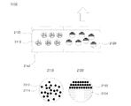
一実施形態において、光の透過度を調節するために、同一符号の電荷に帯電された粒子を用い、前記電場を表示部に局部的に印加して電気泳動(electrophoresis)により前記粒子が局部的に移動する。 In one embodiment, in order to adjust the light transmittance, particles charged to the same sign are used, and the electric field is locally applied to the display unit, and the particles are localized by electrophoresis. Move to.
一実施形態において、光の透過度を調節するために、溶媒と異なる誘電率を有する粒子を用い、不均一な電場を前記表示部に印加する。 In one embodiment, in order to adjust the light transmittance, particles having a dielectric constant different from that of the solvent are used, and a non-uniform electric field is applied to the display unit.
一実施形態において、電気粘性(electrorheology)により前記粒子が前記電場の方向と平行な方向に配列されて透過度が調節される。 In one embodiment, the permeability is adjusted by arranging the particles in a direction parallel to the direction of the electric field by electrorheology.
一実施形態において、前記粒子、溶媒及び溶液のうちの少なくとも1つは、可変電気分極(variable electrical polarization)特性−印加された電場が変化することによって誘発される電気分極量が変わる−を有する。 In one embodiment, at least one of the particles, the solvent and the solution has a variable electrical polarization characteristic—the amount of electrical polarization induced by changing the applied electric field is changed.
一実施形態において、前記粒子、前記溶媒、前記溶液のうちの少なくとも1つは、電子分極、イオン分極、界面分極及び回転分極のうちの何れか1つにより電気分極される物質を含む。 In one embodiment, at least one of the particles, the solvent, and the solution includes a substance that is electrically polarized by any one of electronic polarization, ionic polarization, interface polarization, and rotational polarization.
一実施形態において、前記溶媒は、分極指数が1以上の物質を含む。 In one embodiment, the solvent includes a substance having a polarization index of 1 or more.
一実施形態において、前記溶媒は、炭酸プロピレン(Propylene Carbonate)を含む。 In one embodiment, the solvent comprises propylene carbonate.
一実施形態において、前記粒子は、強誘電体又は超常誘電体物質を含む。 In one embodiment, the particles comprise a ferroelectric or superparaelectric material.
一実施形態において、前記粒子は、Ti、Zr、Ba、Si、Au、Ag、Feのうちの少なくとも1つの元素を含む無機化合物や炭素(Carbon)を含む有機化合物である。 In one embodiment, the particles are an inorganic compound containing at least one element of Ti, Zr, Ba, Si, Au, Ag, and Fe, or an organic compound containing carbon.
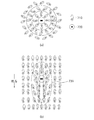
一実施形態によって、前記粒子は同一符号の電荷を有し、前記電場が印加されることによって、電場の強度に比例して粒子に作用する電気泳動力と、前記可変電気分極特性により粒子間に作用する静電気的引力と、同一符号の電荷を有する粒子間に作用する静電気的反発力が相互作用して前記粒子間の間隔が特定の範囲に到達するようになり、前記粒子間の間隔が特定の範囲に到達するようになることによって、前記複数の粒子から特定波長の光が反射される。 According to one embodiment, the particles have the same sign of electric charge, and when the electric field is applied, the electrophoretic force acting on the particles in proportion to the strength of the electric field, and the variable electric polarization property between the particles. The electrostatic attraction force acting and the electrostatic repulsion force acting between particles having the same sign of charge interact to reach a specific range between the particles, and the distance between the particles is specified. By reaching this range, light of a specific wavelength is reflected from the plurality of particles.
一実施形態によって、前記粒子は互いに立体障害効果(steric effect)を示し、前記電場が印加されることによって、前記可変電気分極特性により粒子間に作用する静電気的引力と、前記粒子間に作用する立体障害反発力が相互作用して前記粒子間の間隔が特定の範囲に到達するようになり、前記粒子間の間隔が前記特定の範囲に到達するようになることによって、前記複数の粒子から特定波長の光が反射される。 According to one embodiment, the particles exhibit a steric effect with each other, and when the electric field is applied, electrostatic attraction acting between the particles due to the variable electric polarization property and acting between the particles. The steric hindrance repulsive force interacts so that the interval between the particles reaches a specific range, and the interval between the particles reaches the specific range, thereby identifying the plurality of particles. Wavelength light is reflected.
一実施形態において、前記電場を印加すれば、前記粒子は、溶媒内で3次元的に短範囲規則度(short range ordering)を有しながら、配列する。 In one embodiment, when the electric field is applied, the particles are arranged in a solvent with three-dimensional short range ordering.
一実施形態において、前記電場の強度が増加するほど、前記粒子から反射される光の波長が短くなる。 In one embodiment, the greater the intensity of the electric field, the shorter the wavelength of light reflected from the particles.
一実施形態において、前記粒子から反射される光の可能な波長範囲は、赤外線、可視光線及び紫外線帯域を含む。 In one embodiment, possible wavelength ranges of light reflected from the particles include infrared, visible and ultraviolet bands.
一実施形態において、前記粒子、前記溶媒及び前記電極のうちの少なくとも1つは、顔料及び、染料及び構造色を有する物質のうちの少なくとも1つの成分を含む。 In one embodiment, at least one of the particles, the solvent and the electrode comprises a pigment and at least one component of a dye and a substance having a structural color.
一実施形態において、複数の画素のそれぞれに電場を独立して印加し、前記複数の画素のそれぞれが独立して駆動されるようにする。 In one embodiment, an electric field is independently applied to each of the plurality of pixels so that each of the plurality of pixels is independently driven.
一実施形態において、前記粒子及び前記溶媒は、光透過性物質によってカプセル化されるか、絶縁性物質によって区画化される。 In one embodiment, the particles and the solvent are encapsulated by a light transmissive material or partitioned by an insulating material.
一実施形態において、前記粒子及び前記溶媒は、光透過性物質からなる媒質内に散在する。 In one embodiment, the particles and the solvent are dispersed in a medium made of a light transmissive material.
一実施形態において、前記溶液はゲル(Gel)形態である。 In one embodiment, the solution is in gel form.
一実施形態において、前記溶液は、電場を印加して特定のカラー又は透過度を表示した後に前記電場を除去しても、所定時間前記特定のカラー又は透過度を維持する。 In one embodiment, the solution maintains the specific color or transmittance for a predetermined time even after the electric field is removed after applying the electric field to display the specific color or transmittance.
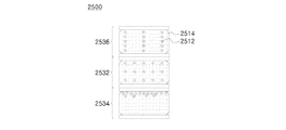
一実施形態において、その内で前記モード間の切替がなされる単一画素を複数垂直に積層させ、各積層された単一画素内で前記モードが独立して実現される。 In one embodiment, a plurality of single pixels that are switched between the modes are stacked vertically, and the modes are independently realized in each stacked single pixel.
一実施形態において、その内で前記モード間の切替がなされる単一画素を複数水平に配列させ、各配列された単一画素内で前記モードが独立して実現される。 In one embodiment, a plurality of single pixels within which the mode is switched are arranged horizontally, and the modes are independently realized in each arranged single pixel.
一実施形態において、前記粒子又は前記溶媒に前記電場を印加した後に前記電場と反対方向の電場を印加して前記粒子の間隔、位置又は配列を初期化(reset)する。 In one embodiment, after applying the electric field to the particles or the solvent, an electric field in a direction opposite to the electric field is applied to reset the spacing, position, or arrangement of the particles.
一実施形態において、前記電場を印加する前に前記粒子の間隔、位置又は配列を予め設定された間隔、位置又は配列に維持するために待機(standby)電場を印加する。 In one embodiment, prior to applying the electric field, a standby electric field is applied to maintain the spacing, position or arrangement of the particles at a preset interval, position or arrangement.
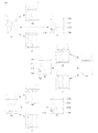
一実施形態において、前記表示部にキャパシタが接続されて電圧が印加されれば、前記キャパシタに電荷が充電されるようにし、前記表示部に印加される電圧が遮断されれば、前記キャパシタに充電された電荷を用いて前記表示部に電圧を印加する。 In one embodiment, if a capacitor is connected to the display unit and a voltage is applied, the capacitor is charged. If the voltage applied to the display unit is cut off, the capacitor is charged. A voltage is applied to the display unit using the generated charges.
一実施形態において、表示面積、表示時間及び光透過度のうちの少なくとも1つを調節することで、表示されるカラーの明度又は彩度を制御する。 In one embodiment, the brightness or saturation of the displayed color is controlled by adjusting at least one of display area, display time, and light transmission.
一実施形態において、互いに異なる符号の電荷を有する第1及び第2粒子に電場を印加して前記第1粒子の間隔、位置又は配列と前記第2粒子の間隔、位置又は配列が互いに独立して制御される。 In one embodiment, an electric field is applied to first and second particles having different signs of charge so that the interval, position or arrangement of the first particles and the interval, position or arrangement of the second particles are independent of each other. Be controlled.
一実施形態において、前記粒子及び前記溶媒に入射される光を用いてエネルギーを発生させ、前記発生したエネルギーを用いて前記電場を印加する。 In one embodiment, energy is generated using light incident on the particles and the solvent, and the electric field is applied using the generated energy.
一実施形態において、発光型表示手段を用いて前記モードを実現するか、発光型表示手段を前記モードと組み合わせて用いる。 In one embodiment, the mode is realized using a light emitting display means, or the light emitting display means is used in combination with the mode.
一実施形態において、前記粒子、前記溶媒又は前記電極から反射されるか、前記粒子、前記溶媒又は前記電極を透過する光が前記電極に結合されているカラーフィルタを通過して表示されるようにする。 In one embodiment, light reflected from the particle, the solvent or the electrode or transmitted through the particle, the solvent or the electrode is displayed through a color filter coupled to the electrode. To do.
一実施形態において、前記粒子及び前記電極は、それぞれ白色及び黒色であるか、それぞれ黒色及び白色である。 In one embodiment, the particles and the electrodes are white and black, respectively, or black and white, respectively.
一実施形態において、前記粒子の間隔を制御することによって反射される光の波長を調節するモードは、前記粒子の配列を制御することによって光の透過度を調節するモードよりもその印加される電圧の大きさが小さい。 In one embodiment, the mode of adjusting the wavelength of the reflected light by controlling the spacing of the particles is more than the applied voltage than the mode of adjusting the light transmission by controlling the arrangement of the particles. The size of is small.
一実施形態において、印加される電圧が大きくなるほど、可変電気分極特性による粒子間の引力が粒子間の反発力よりも反発力を無視する程度に大きくなる。 In one embodiment, the greater the applied voltage, the greater the attractive force between the particles due to the variable electrical polarization characteristics to the extent that the repulsive force is ignored than the repulsive force between the particles.
一実施形態において、前記粒子の配列を制御することによって光の透過度を調節するモードでは、前記可変電気分極特性による粒子間の引力が粒子間の反発力よりも大きくなる。 In one embodiment, in the mode in which the light transmittance is adjusted by controlling the arrangement of the particles, the attractive force between the particles due to the variable electric polarization characteristic is larger than the repulsive force between the particles.
一実施形態において、透過度調節モードで、透過度が連続的に又はアナログ方式で変化され得る。 In one embodiment, in the transparency adjustment mode, the transparency can be changed continuously or in an analog fashion.
本発明によれば、多様な色又は連続的な色及び/又は透過度が同一の単一画素内で簡単な構造で実現され得るという効果を奏する。 According to the present invention, there is an effect that various colors or continuous colors and / or transparency can be realized with a simple structure in the same single pixel.
本発明によれば、多様な色、透過度、彩度及び/又は明度が簡単な構造で調節され得る。 According to the present invention, various colors, transparency, saturation and / or brightness can be adjusted with a simple structure.
本発明によれば、R、G、Bの混色による色(hue)実現ではなく、連続的な波長の光を反射させることで、連続的な波長の色を実現できる。 According to the present invention, a color having a continuous wavelength can be realized by reflecting light having a continuous wavelength instead of realizing a color (hue) by mixing R, G, and B colors.
本発明に係る表示方法によれば、大型面積表示、簡単な表示方法、連続的な色実現、フレキシブルな表示領域での使用、低電力消費の表示を同時に満たすことができる。 According to the display method of the present invention, large area display, simple display method, continuous color realization, use in a flexible display area, and low power consumption display can be satisfied at the same time.
本発明によれば、視野角(viewing angle)特性及び反応速度(response time)に優れた表示方法及び装置が提供され得る。 ADVANTAGE OF THE INVENTION According to this invention, the display method and apparatus excellent in the viewing angle characteristic and the response speed (response time) can be provided.
本発明の前述した長所、特徴及び目的と更なる長所、特徴及び目的は、次の発明の詳細な説明を以下の添付する図面を参照して説明すれば、明らかになる。 The foregoing advantages, features and objects of the present invention as well as further advantages, features and objects will become apparent from the following detailed description of the invention when read in conjunction with the accompanying drawings.
後述する本発明に関する詳細な説明は、本発明が実施され得る特定の実施形態を例として示す添付の図面を参照する。これらの実施形態は、当業者が本発明を実施できるのに十分なように詳細に説明される。本発明の多様な実施形態は互いに異なるが、相互排他的である必要はないことが理解されるべきである。例えば、ここに記載されている特定の形状、構造及び特性は一実施形態と関連して本発明の精神及び範囲から逸脱せず、他の実施形態で実現され得る。また、それぞれの開示された実施形態内の個別の構成要素の位置又は配置は、本発明の精神及び範囲から逸脱せず、変更され得ることが理解されるべきである。本明細書全般に亘って用いられる表現である「一実施形態によって」又は「一実施形態において」が登場すれば、これは特定の一実施形態で記述された形状、構造、特性、方式、構成などが必ずしも全ての実施形態でも同一に適用されることを意味せず、また特定の実施形態で記述された形状、構造、特性、方式、構成などがこの特定の実施形態にのみ適用されることを意味するわけでもない。更に、特定の実施形態で用いられる形状、構造、特徴部、特性、構成などは、他の実施形態と互いに結合され得る。 The following detailed description of the invention refers to the accompanying drawings that illustrate, by way of illustration, specific embodiments in which the invention may be practiced. These embodiments are described in sufficient detail to enable those skilled in the art to practice the invention. It should be understood that the various embodiments of the present invention are different from each other but need not be mutually exclusive. For example, the specific shapes, structures, and characteristics described herein may be realized in other embodiments without departing from the spirit and scope of the invention in connection with one embodiment. It should also be understood that the location or arrangement of individual components within each disclosed embodiment may be changed without departing from the spirit and scope of the present invention. Where the expression “in one embodiment” or “in one embodiment” is used throughout this specification, this is the shape, structure, characteristic, scheme, configuration described in a particular embodiment. Does not necessarily mean that the same applies to all embodiments, and the shape, structure, characteristics, method, configuration, etc. described in a specific embodiment apply only to this specific embodiment. Does not mean. Further, the shapes, structures, features, characteristics, configurations, etc. used in a particular embodiment may be combined with each other.
また、本明細書で用いられる名詞の単数型は、複数型の存在を排除しない。また、本明細書で用いられる用語である「含む」及び「有する」及び「備える」及びこれらの活用語は、記述された構成要素又は段階以外の構成要素又は段階の存在を排除しない。また、本明細書で用いられるプロセスの段階の順序は、本明細書で記述された通りにのみ限定されるものではなく、他の順序も可能である。本明細書で用いられる序数である「第1、第2、第3」などは、構成要素又はモード又は段階を相互間で区別するだけであって、いかなる順序上の意味も与えず、また特定のモードは、第1モード、第2モード又は第3モードとも指称され得る。仮に、本明細書において、第1モードは光結晶反射モードを示すが、請求の範囲では第1モードは光結晶反射モード以外の他のモードになり得る。また、本明細書において、第2モードは、固有色反射モードを示し得るが、請求の範囲では固有色反射モード以外の他のモードになり得る。これはまた第3モードに対しても適用される。即ち、本発明を体系的に説明するために、第1モードを光結晶反射モード、第2モードを固有色反射モード、第3モードを透過度調節モードにし、本明細書で各モードを説明しているが、本発明は、このような説明方式にのみ限定されない。 In addition, singular forms of nouns used in this specification do not exclude the presence of plural forms. Further, the terms “including”, “having” and “comprising”, which are used in the present specification, and their usage terms do not exclude the presence of a component or a step other than the described component or step. Also, the order of the process steps used herein is not limited only as described herein, and other orders are possible. As used herein, ordinal numbers such as “first, second, third” only distinguish components or modes or steps from each other, do not give any ordering meaning, and are specific This mode may also be referred to as a first mode, a second mode, or a third mode. In the present specification, the first mode indicates the photonic crystal reflection mode, but in the claims, the first mode can be a mode other than the photonic crystal reflection mode. Further, in the present specification, the second mode may indicate an intrinsic color reflection mode, but may be a mode other than the intrinsic color reflection mode in the claims. This also applies to the third mode. That is, in order to systematically explain the present invention, the first mode is the photonic crystal reflection mode, the second mode is the intrinsic color reflection mode, and the third mode is the transmittance adjustment mode. However, the present invention is not limited to such an explanation method.
従って、後述する詳細な説明は、限定的な意味として捉えようとするものではなく、本発明の範囲は、適切に説明されるのであれば、それらの請求項が主張するものと均等なあらゆる範囲と共に添付された請求項によってのみ限定される。図面における類似する参照符号は、多様な側面に亘って同一又は類似の機能を示す。 Accordingly, the detailed description set forth below is not intended to be construed in a limiting sense, and the scope of the present invention is, if properly described, any scope equivalent to that claimed by those claims. And is limited only by the claims appended hereto. Like reference symbols in the drawings indicate the same or similar functions throughout the various aspects.
以下、本発明の属する技術分野において通常の知識を有する者が本発明を容易に実施できるようにするために、添付の図面を参照して本発明の構成を詳細に説明する。 Hereinafter, in order to enable a person having ordinary knowledge in the technical field of the present invention to easily implement the present invention, the configuration of the present invention will be described in detail with reference to the accompanying drawings.
表示装置の構成 Configuration of display device
本発明の一実施形態に係る表示装置は、複数の粒子が溶媒内に分散された状態で電極を通じて電場を印加し、電場の強度、方向、印加時間、印加回数、印加領域のうちの少なくとも1つを調節して粒子の間隔、位置及び配列のうちの少なくとも1つを制御することで、粒子で構成される光結晶から反射される光のカラーを表示する第1モード(光結晶反射モード)、粒子、溶媒、電極などの固有のカラー又は粒子の散乱による溶液のカラーを表示する第2モード(固有色反射モード)及び透過度が制御された光のカラーを表示する(即ち、光の透過度を制御する)第3モード(透過度調節モード)のうちの少なくとも2つのモードを表示装置の表示領域又は表示部の同一の単一画素(unit pixel)内で互いに切替可能に選択的に実現できる。以下の説明からも分かるように、単一画素とは、独立して制御され得る最小の表示単位のことをいう。即ち、既存のディスプレイ方式では、赤色のセル、緑色のセル、青色のセルが1つの単一画素を形成できるが、これはR、G、Bカラーの混色によって色を実現する方式における、仮に3つのセルが1つの単一画素を形成するが、本技術では、1つの単一セル又は単一画素が独立して制御されて連続的な色を実現できるので、本明細書における単一画素とは、既存の方式とは異なり、独立して制御され得る最小の表示単位又は表示領域又は表示部を意味することに注目する必要がある。 A display device according to an embodiment of the present invention applies an electric field through an electrode in a state where a plurality of particles are dispersed in a solvent, and at least one of the intensity, direction, application time, number of applications, and application region of the electric field. The first mode (photonic crystal reflection mode) displays the color of the light reflected from the photonic crystal composed of particles by controlling the spacing, position and arrangement of the particles by adjusting the particle size A second mode (intrinsic color reflection mode) that displays the intrinsic color of particles, solvents, electrodes, etc. or the color of the solution due to particle scattering and the color of light with controlled transmission (ie, light transmission) At least two of the third modes (transmittance adjustment modes) can be switched selectively within the same single pixel of the display area or display unit of the display device. it can. As can be seen from the following description, a single pixel refers to the smallest display unit that can be controlled independently. That is, in the existing display method, a red cell, a green cell, and a blue cell can form one single pixel. This is a method that realizes a color by mixing R, G, and B colors. Although one cell forms one single pixel, the present technology allows a single pixel or single pixel to be independently controlled to achieve a continuous color. It should be noted that, unlike existing methods, means the smallest display unit or display area or display unit that can be controlled independently.
粒子及び溶媒の構成 Particle and solvent composition
図1及び図2は、本発明の一実施形態に係る表示装置に含まれる粒子の構成を例示的に示す図である。 1 and 2 are views exemplarily showing a configuration of particles included in a display device according to an embodiment of the present invention.
まず、図1を参照すれば、本発明の一実施形態に係る粒子110は、溶媒120に分散されて溶液状態で存在し得る。本発明の一実施形態によれば、粒子110は、正電荷又は負電荷を有し得る。従って、粒子110に電場が印加される場合、粒子110の有する電荷と電場により発生する電気的引力によって粒子110が移動(即ち、電気泳動)し得る。また、複数の粒子110が同一符号の電荷を有する場合には、同一符号の電荷による相互間の電気的斥力(クーロン反発力)によって複数の粒子110が互いに接触せず、所定の間隔を維持した状態で配列され得る。また、本発明の一実施形態によれば、粒子110は、高分子鎖形態などでコーティングされ、粒子間高分子鎖の無秩序な運動などによる立体障害効果が存在し得る。従って、粒子間の立体障害効果によって複数の粒子110が互いに接触せず、所定の間隔を維持した状態で配列され得る。
First, referring to FIG. 1, the
図2を参照すれば、本発明の一実施形態に係る粒子110は、図2の(a)のように、異種の物質からなるコア−シェル(core-shell)112形態で構成されてもよく、図2の(b)のように、異種の物質からなるマルチ−コア(multi-core)114形態で構成されてもよく、図2の(c)のように、複数のナノ粒子からなるクラスタ116で構成されてもよく、前述した電荷を有する電荷層118又は立体障害効果を示す層118がそれらの粒子を覆う構造で構成されてもよい。本発明に係る粒子は、前記構造に限定されず、コア粒子に異種物質を浸透或いは担持させた構造、ラズベリー(raspberry)構造などのように、多様な粒子及び形態を利用でき、逆光結晶構造のように、空孔(cavity)構造も使用できる。
Referring to FIG. 2, the
より具体的に、本発明の一実施形態に係る粒子110は、シリコン(Si)、チタニウム(Ti)、バリウム(Ba)、ストロンチウム(Sr)、鉄(Fe)、ニッケル(Ni)、コバルト(Co)、鉛(Pb)、アルミニウム(Al)、銅(Cu)、銀(Ag)、金(Au)、タングステン(W)、モリブデン(Mo)、亜鉛(Zn)、ジルコニウム(Zr)などの元素やこれらを含む酸化物、窒化物などの化合物からなり得る。また、本発明の一実施形態に係る粒子110は、スチレン、ピリジン、ピロール、アニリン、ピロリドン、アクリレート、ウレタン、チオフェン、カルバゾール、フルオレン、ビニルアルコール、エチレングリコール、エトキシアクリレートのうちの少なくとも1つの単位体を含む有機高分子又はPS(polystyrene)、PE(polyethylene)、PP(polypropylene)、PVC(polyvinyl chloride)、PET(polyethylen terephthalate)などの高分子物質からなり得る。
More specifically, the
また、本発明の一実施形態に係る粒子110は、電荷を有さない粒子或いはクラスタ(cluster)に電荷を有する物質がコーティングされた形態として構成されてもよい。例えば、炭化水素基を有する有機化合物によって表面が加工(或いはコーティング)された粒子、カルボン酸(carboxylic acid)基、エステル(ester)基、アシル(acyl)基を有する有機化合物によって表面が加工(或いはコーティング)された粒子、ハロゲン(F、Cl、Br、Iなど)元素を含む錯化合物によって表面が加工(コーティング)された粒子、アミン(amine)、チオール(thiol)、ホスフィン(phosphine)を含む配位化合物によって表面が加工(コーティング)された粒子、表面にラジカルを形成することによって電荷を有する粒子がこれに該当し得る。このように、粒子110の表面をシリカ、高分子、高分子モノマーなどの物質でコーティングすることで、粒子110が溶媒120内で高い分散性と安定性を有するようにできる。
In addition, the
一方、粒子110の直径は数nm〜数百μmであり得るが、必ずしもこれに限定されるものではなく、外部電場により粒子が一定間隔で配列されるとき、ブラッグの法則(Bragg's law)により粒子の屈折率及び溶媒の屈折率と連係して可視光領域の光結晶波長帯が含まれ得る粒子サイズに設定できる。
On the other hand, the diameter of the
一方、本発明の一実施形態によれば、粒子110は、特定波長の光を反射させることができるように、即ち、固有のカラーを有するように構成され得る。より具体的に、本発明の一実施形態に係る粒子110は、酸化数の調節又は無機顔料、顔料などのコーティングを通じて特定のカラーを有するようになり得る。例えば、本発明に係る粒子110にコーティングされる無機顔料としては、発色団を含むZn、Pb、Ti、Cd、Fe、As、Co、Mg、Alなどが酸化物、硫化物、硫酸塩の形態で使用され得、本発明に係る粒子110にコーティングされる染料としては、蛍光染料、酸性染料、塩基性染料、媒染染料、硫化染料、建染染料、分散染料、反応性染料などが使用され得る。また、本発明の一実施形態によれば、粒子110は、特定のカラーを表示できるように、特定の構造色(structural color)を有する物質でもあり得る。例えば、シリコン酸化物(SiOx)、チタニウム酸化物(TiOx)などの粒子が屈折率の異なる媒体に一定間隔で均一に配列された形態で構成され、特定波長の光を反射させる物質であり得る。
Meanwhile, according to an embodiment of the present invention, the
また、本発明の一実施形態によれば、溶媒120も特定波長の光を反射させることができるように、即ち、固有のカラーを有するように構成され得る。より具体的に、本発明に係る溶媒120は、無機顔料、染料を有する物質を含むか、光結晶による構造色を有する物質を含むことができる。 In addition, according to an embodiment of the present invention, the solvent 120 may also be configured to reflect a specific wavelength of light, that is, to have a unique color. More specifically, the solvent 120 according to the present invention may include a substance having an inorganic pigment or a dye, or a substance having a structural color due to photocrystal.
更に、本発明の一実施形態によれば、前記粒子又は溶媒に蛍光物質、燐光物質、発光物質などが少なくとも1つ含まれ、本発明の効果を最大化させることができる。
本発明の一実施形態によれば、溶媒120は、粒子110が溶媒120内に均一に分散されてコロイド安定性を確保するために、粒子110が溶媒120内で安定して分散されるように、分散剤などの添加剤を溶媒に添加するか、あるいは粒子110と溶媒120の比重差が既に設定された値以下であり得、溶媒120の粘度が既に設定された値以上であり得、粒子110と溶媒120からなるコロイド溶液の界面動電位(electrokinetic potential)(即ち、ゼータ電位)の値が既に設定された値以上に高くなり得る。
Furthermore, according to an embodiment of the present invention, at least one of a fluorescent material, a phosphorescent material, a luminescent material, and the like is included in the particles or the solvent, so that the effect of the present invention can be maximized.
According to an embodiment of the present invention, the solvent 120 may be dispersed stably in the solvent 120 so that the
また、本発明の一実施形態によれば、電場の印加時に、粒子110が溶媒120内で所定の配列を通じて発生する可視光領域の反射光の強度を大きくするために、溶媒120と粒子110の屈折率差が既に設定された値以上であり得、粒子110の大きさは、ブラッグの法則により粒子の屈折率及び溶媒の屈折率と連係して可視光領域の光結晶波長帯が含まれ得る粒子サイズに設定できる。
In addition, according to an embodiment of the present invention, in order to increase the intensity of the reflected light in the visible region generated by the
例えば、コロイド溶液の界面動電位の絶対値は10mV以上であることができ、粒子110と溶媒120の比重差は5以下であることができ、粒子110と溶媒120の屈折率差は0.3以上であり、粒子の大きさは100nm〜500nmの間であることができるが、これに限定されるものではない。
For example, the absolute value of the electrokinetic potential of the colloidal solution can be 10 mV or more, the specific gravity difference between the
粒子間引力:電気分極特性 Interparticle attractive force: Electric polarization characteristics
また、本発明の一実施形態によれば、表示装置に含まれる粒子が分散された溶媒を含む溶液は、可変電気分極(variable electrical polarization)特性−電場が印加されれば、電気分極量が変化する−を有し得るが、このような溶液の電気分極特性は、溶液を構成している粒子又は溶媒のうちの少なくとも1つが電気分極特性を示すか、溶液内で粒子と溶媒の相互作用により電気分極特性が示され得る。また、電気分極特性を示す溶液(粒子及び溶媒で構成)は、原子或いは分子の非対称的な電荷分布などによって外部電場が印加されることにより、電子分極、イオン分極、界面分極及び回転分極のうちの何れか1つにより電気分極される物質を含むことができる。 In addition, according to an embodiment of the present invention, a solution including a solvent in which particles included in a display device are dispersed has a variable electrical polarization characteristic—an electric polarization amount is changed when an electric field is applied. However, the electric polarization characteristics of such a solution may be due to the interaction between the particles and the solvent in the solution, or at least one of the particles or the solvent constituting the solution exhibits the electric polarization characteristics. Electrical polarization characteristics can be shown. In addition, a solution (consisting of particles and a solvent) exhibiting electric polarization characteristics is applied to an external electric field by an asymmetric charge distribution of atoms or molecules, and thus, among electronic polarization, ionic polarization, interface polarization, and rotational polarization. A material that is electrically polarized by any one of the above can be included.
従って、本発明の一実施形態に係る粒子又は溶媒又はこれらで構成された溶液のうちの少なくとも1つは、電場が印加されれば、電気分極が誘発され得、印加される電場の強度又は方向が変わることによって、前記誘発された電気分極量が変わり得る。このように電場が変わることにより、電気分極量が変わる特性を可変電気分極特性と言える。本発明において、電場が印加された際に誘発される電気分極量が大きければ大きいほど、有利であるが、その理由は、電場を印加するにつれて、粒子、溶媒、溶液のうちの少なくとも1つの電気分極により粒子間の相互作用力がより大きく作用し、粒子間の間隔を更に均一に配列できるためである。 Therefore, at least one of the particles or the solvent according to an embodiment of the present invention or a solution composed thereof may induce an electric polarization if an electric field is applied, and the intensity or direction of the applied electric field. Can change the induced amount of electric polarization. A characteristic in which the amount of electric polarization changes by changing the electric field in this way can be said to be a variable electric polarization characteristic. In the present invention, the larger the amount of electric polarization induced when an electric field is applied, the more advantageous. The reason is that as the electric field is applied, the electric polarization of at least one of particles, solvents and solutions is increased. This is because the interaction force between the particles acts more greatly by the polarization, and the intervals between the particles can be arranged more uniformly.
図3は、本発明の一実施形態によって電場が印加されることによって、粒子又は溶媒が分極される構成を例示的に示す図である。 FIG. 3 is a view exemplarily showing a configuration in which particles or a solvent are polarized by applying an electric field according to an embodiment of the present invention.
図3の(a)及び(b)を参照すれば、外部電場が印加されない場合に、粒子又は溶媒が電気的平衡状態を維持し、電気分極特性を示さないが、外部電場が印加される場合には、粒子又は溶媒内の電荷が所定方向に移動することによって分極が誘発され、粒子又は溶媒が分極され得る。図3の(c)及び(d)は、粒子又は溶媒を構成する電気的に非対称的な構成要素によって単位分極(unit polarization)が生成される場合であって、電場を印加しない場合には、前記単位分極が無秩序に配列されて全体電気分極は現れないか、小さな値を示すが、外部から電場が印加される場合には、単位分極を有する粒子又は溶媒が外部電場の方向によって所定の方向に再配列され得るため、全体として、単位分極がない状態で電場を印加する図3の(b)の場合に比べて、相対的に大きな電気分極値(polarization value)を示すことができる。本発明の一実施形態によれば、図3(c)及び(d)に表示された単位分極は、電子又はイオンの非対称的な配置や分子の非対称的な構造で発生し得、このような単位分極によって外部電場が印加されない場合にも、微細な残留分極値(remnant polarization value)が示され得る。 Referring to FIGS. 3A and 3B, when an external electric field is not applied, the particles or the solvent maintain an electrical equilibrium state and do not exhibit electric polarization characteristics, but an external electric field is applied. In other words, polarization is induced by the movement of electric charges in the particles or the solvent in a predetermined direction, and the particles or the solvent can be polarized. 3 (c) and 3 (d) show a case where unit polarization is generated by an electrically asymmetric component constituting a particle or solvent, and when no electric field is applied, When the unit polarization is randomly arranged and the entire electric polarization does not appear or shows a small value, when an electric field is applied from the outside, the particles or the solvent having the unit polarization have a predetermined direction depending on the direction of the external electric field. Therefore, as a whole, a relatively large polarization value can be shown as compared with the case of FIG. 3B in which an electric field is applied in the absence of unit polarization. According to one embodiment of the present invention, the unit polarization shown in FIGS. 3C and 3D may occur in an asymmetric arrangement of electrons or ions or an asymmetric structure of molecules. Even when no external electric field is applied due to unit polarization, a fine remnant polarization value may be indicated.
図4は、本発明の一実施形態によって分子の非対称的な配置による単位分極特性を例示的に示す図である。より具体的に、図4は、水分子(H2O)の場合を例示的に示すものであって、水分子以外に、トリクロロエチレン、四塩化炭素、ジイソプロピルエーテル、トルエン、メチル−t−ブチルエーテル、キシレン、ベンゼン、ジエチルエーテル、ジクロロメタン、1,2−ジクロロエタン、酢酸ブチル、イソプロパノール、n−ブタノール、テトラヒドロフラン、n−プロパノール、クロロホルム、酢酸エチル、2−ブタノン、ジオキサン、アセトン、メタノール、エタノール、アセトニトリル、酢酸、ジメチルホルムアミド、ジメチルスルホキシド、炭酸プロピレン、N,N−ジメチルホルムアミド、ジメチルアセトアミド、N−メチルピロリドンなどは、分子構造の非対称性により単位分極特性が現れ得るため、本発明に係る粒子又は溶媒を構成する物質として採用され得る。参考までに、物質の分極特性を比較するために用いられる極性指数(polarity index)は、水(H2O)の分極特性に対比して該当物質の相対的な分極の程度を示す指標であり得、本発明の一実施形態によれば、溶媒は、極性指数が1以上の物質を含むことができる。 FIG. 4 is a diagram illustrating unit polarization characteristics according to an asymmetric arrangement of molecules according to an exemplary embodiment of the present invention. More specifically, FIG. 4 exemplarily shows the case of a water molecule (H 2 O). In addition to the water molecule, trichloroethylene, carbon tetrachloride, diisopropyl ether, toluene, methyl-t-butyl ether, Xylene, benzene, diethyl ether, dichloromethane, 1,2-dichloroethane, butyl acetate, isopropanol, n-butanol, tetrahydrofuran, n-propanol, chloroform, ethyl acetate, 2-butanone, dioxane, acetone, methanol, ethanol, acetonitrile, acetic acid , Dimethylformamide, dimethyl sulfoxide, propylene carbonate, N, N-dimethylformamide, dimethylacetamide, N-methylpyrrolidone, etc. may exhibit unit polarization characteristics due to the asymmetry of the molecular structure. It may be employed as the material constituting the. For reference, the polarity index used to compare the polarization characteristics of substances is an index indicating the relative degree of polarization of the substance relative to the polarization characteristics of water (H 2 O). Thus, according to an embodiment of the present invention, the solvent may include a substance having a polarity index of 1 or more.
また、本発明の一実施形態に係る粒子又は溶媒は、外部電場が印加されることによって、イオン又は原子の電気分極が追加で誘発され、分極量が大きく増加し、外部電場が印加されない場合にも、残留分極量が存在し、電場の印加方向によって履歴(hysteresis)が残る強誘電性(ferroelectric)物質を含むことができ、外部電場が印加されることによって、イオン又は原子分極が追加で誘発され、分極量が大きく増加するが、外部電場が印加されない場合には、残留分極量と履歴が残っていない超常誘電性(superparaelectric)物質を含むことができる。図5を参照すれば、常誘電性物質510、強誘電性物質520及び超常誘電性物質530の外部電場による履歴曲線を確認することができる。
In addition, the particles or the solvent according to the embodiment of the present invention may be applied when an external electric field is applied to additionally induce electric polarization of ions or atoms, the polarization amount greatly increases, and no external electric field is applied. In addition, there may be a ferroelectric material in which a residual polarization amount exists and a hysteresis is left depending on the direction in which the electric field is applied, and an ion or atomic polarization is additionally induced by applying an external electric field. If the external electric field is not applied, the amount of polarization can be increased, but a superparaelectric material having no residual polarization and history can be included. Referring to FIG. 5, the hysteresis curves of the
更に、本発明の一実施形態に係る粒子又は溶媒は、ペロブスカイト(perovskite)構造を有する物質を含むことができるが、ABO3のようなペロブスカイト構造を有する物質として、PbZrO3、PbTiO3、Pb(Zr、Ti)O3、SrTiO3、BaTiO3、(Ba、Sr)TiO3、CaTiO3、LiNbO3などの物質がその例として挙げられる。 Further, the particles or the solvent according to an embodiment of the present invention may include a material having a perovskite structure, but as a material having a perovskite structure such as ABO 3 , PbZrO 3 , PbTiO 3 , Pb ( Examples include Zr, Ti) O 3 , SrTiO 3 , BaTiO 3 , (Ba, Sr) TiO 3 , CaTiO 3 , LiNbO 3 and the like.
図6は、本発明の一実施形態に係る粒子又は溶媒に含まれ得るペロブスカイト構造を有する物質を例示的に示す図である。図6を参照すれば、PbZrO3(又はPbTiO3)に印加される外部電場の方向によってPbZrO3(又はPbTiO3)内でのZr(又はTi)(即ち、ABO3構造でのB)の位置が変わり得、これによってPbZrO3(又はPbTiO3)全体の極性が変わり得る。従って、原子或いはイオンの移動により非対称的な電子分布が形成され、単位分極が形成され得、このような単位分極が存在すれば、電子分極のみ存在する場合に比べて、外部電場の印加時に更に大きな可変電気分極値を誘発させることができる。 FIG. 6 is a view exemplarily illustrating a substance having a perovskite structure that can be included in a particle or a solvent according to an embodiment of the present invention. Referring to FIG. 6, the position of Zr in PbZrO 3 (or PbTiO 3) PbZrO 3 depending on the direction of the applied external electric field (or PbTiO 3) in (or Ti) (i.e., B in ABO 3 structure) Can change, which can change the overall polarity of PbZrO 3 (or PbTiO 3 ). Accordingly, an asymmetric electron distribution can be formed due to the movement of atoms or ions, and unit polarization can be formed. When such unit polarization exists, it can be further increased when an external electric field is applied, compared to the case where only electron polarization exists. Large variable electrical polarization values can be induced.
また、本発明の一実施形態によれば、本発明の反射光調節及び透過度調節効果は、粒子間配列がよくなされればなされるほど、最大化し得るため、微細粒子が不導体流体に分散されて電気流変(ER:Electro-Rheology)特性を示す流体又は更に不導体がコーティングされた強誘電体粒子のように極大電気流変(GER:Giant Electro-Rheology)を示す流体を利用することで、本発明の効果を最大化できる。 In addition, according to an embodiment of the present invention, the reflected light adjustment and transmittance adjustment effect of the present invention can be maximized as the inter-particle arrangement is improved, so that the fine particles are dispersed in the non-conductive fluid. A fluid exhibiting ER (Electro-Rheology) characteristics or a fluid exhibiting GE (Giant Electro-Rheology) such as a ferroelectric particle coated with a non-conductor Thus, the effect of the present invention can be maximized.
更に、電気分極の様相を説明すると、第1実施例として電場が印加されなければ、前記溶媒の各分子及び各粒子のうちの少なくとも1つは、いかなる電気分極量も有さないが、電場が印加されれば、前記溶媒の各分子及び各粒子のうちの少なくとも1つは電気的に分極され、これにより、前記複数の粒子の電気分極量全体及び前記溶媒の電気分極量全体のうちの少なくとも1つは増加するようになり得る。第2実施例では、電場が印加されなくても、前記溶媒の各分子及び各粒子のうちの少なくとも1つは、電気的に分極されているが、前記溶媒の電気分極量全体及び前記複数の粒子の電気分極量全体のうちの少なくとも1つはゼロになり、電場が印加されれば、前記複数の粒子の電気分極量全体及び前記溶媒の電気分極量全体のうちの少なくとも1つは、増加するようになり得る。第3実施例として、電場が印加されなくても、前記溶媒の各分子及び各粒子のうちの少なくとも1つは、電気的に分極されており、前記溶媒の電気分極量全体及び前記複数の粒子の電気分極量全体のうちの少なくとも1つは、ゼロでない第1値を有し、電場が印加されれば、前記複数の粒子の電気分極量全体及び前記溶媒の電気分極量全体のうちの少なくとも1つは、前記第1値よりも大きい第2値になり得る。 Further, the aspect of electric polarization will be described. As an example, if no electric field is applied, at least one of the molecules and particles of the solvent does not have any electric polarization amount, but the electric field is When applied, at least one of each molecule and each particle of the solvent is electrically polarized, whereby at least one of the total electrical polarization of the plurality of particles and the total electrical polarization of the solvent. One can become increased. In the second embodiment, even if no electric field is applied, at least one of each molecule and each particle of the solvent is electrically polarized, but the total amount of electric polarization of the solvent and the plurality of the plurality of particles are electrically polarized. At least one of the total amount of electric polarization of the particles becomes zero, and if an electric field is applied, at least one of the total amount of electric polarization of the plurality of particles and the total amount of electric polarization of the solvent increases. Can become. As a third embodiment, even if no electric field is applied, at least one of the molecules and particles of the solvent is electrically polarized, and the entire amount of electric polarization of the solvent and the plurality of particles At least one of the total electric polarization amounts of the plurality of particles has a first non-zero value, and if an electric field is applied, at least one of the total electric polarization amount of the plurality of particles and the total electric polarization amount of the solvent. One may be a second value that is greater than the first value.
粒子間反発力:クーロン効果又は立体障害効果 Interparticle repulsive force: Coulomb effect or steric hindrance effect
本発明の一実施形態によれば、表示装置に含まれる粒子表面は、同一符号の電荷に帯電され、粒子によりクーロン反発力が形成されるか、粒子表面に高分子鎖構造、官能基(functional group)、添加剤(surfactant)などを用いて立体構造物などを形成させて立体障害反発力(steric hindrance repulsion)が形成され得る。 According to an embodiment of the present invention, the particle surface included in the display device is charged with the same sign of charge, and a Coulomb repulsive force is formed by the particle, or a polymer chain structure, functional group (functional group) is formed on the particle surface. A steric hindrance repulsion can be formed by forming a three-dimensional structure or the like using a group, an additive or the like.
また、本発明の一実施形態によれば、粒子間反発力を最大化するために、前記同一符号の電荷に帯電され、立体構造物の形態で粒子をコーティングして前記コーロン反発力と立体障害反発力を同時に誘発させることもできる。 Also, according to an embodiment of the present invention, in order to maximize the repulsive force between particles, the Kohlon repulsive force and the steric hindrance are coated by charging the particles in the form of a three-dimensional structure charged with the same charge. A repulsive force can be triggered at the same time.
更に、本発明の一実施形態によれば、粒子は電気分極される物質を含み、粒子表面処理を通じて粒子間の立体障害反発力はあるが、帯電された電荷が弱いため、電気泳動効果は最小化するように構成することによって、前記粒子或いは溶液は、外部電場により電気分極量が変化し、粒子間の局部的引力(short range attraction)が効果的に発生し、粒子表面処理を通じて形成された立体構造物により粒子間で局部的に立体障害反発力(short range steric hindrance repulsion)は効果的に発生するが、外部電場による長距離電気泳動力(long range electophoretic force)により帯電された粒子が電極に偏る現象を最小化できる。即ち、粒子表面に電荷が処理されず、外部電場によって何れか1つの電極側に電気泳動する現象が最小化され得る。このように立体障害反発力を与えるために、有機リガンド(organic ligand)を粒子表面に処理できる。また、本発明の一実施形態によれば、帯電された粒子を使用する際に、前記電気泳動により帯電された粒子が電極に偏る現象を防止するために、直流電圧ではない交流電圧を組み合わせて使用することもできる。 Furthermore, according to an embodiment of the present invention, the particles include an electropolarized substance, and there is a steric hindrance repulsion between the particles through the particle surface treatment, but since the charged charge is weak, the electrophoretic effect is minimized. The particle or solution is formed through the particle surface treatment by changing the amount of electric polarization by an external electric field and effectively generating a short range attraction between the particles. The three-dimensional structure effectively generates a short range steric hindrance repulsion between the particles, but the particles charged by the long range electophoretic force due to the external electric field are the electrodes. Can be minimized. That is, a phenomenon in which no charge is processed on the particle surface and electrophoresis to one of the electrodes due to an external electric field can be minimized. Thus, in order to give a steric hindrance repulsive force, an organic ligand can be treated on the particle surface. In addition, according to an embodiment of the present invention, when using charged particles, in order to prevent the phenomenon that the particles charged by electrophoresis are biased to the electrode, an AC voltage that is not a DC voltage is combined. It can also be used.
但し、本発明に係る粒子及び溶媒の構成が必ずしも前記列挙したものに限定されるものではなく、本発明の目的を達成できる範囲内で、即ち、電場によって粒子の間隔が制御され得る範囲内で適切に変更され得ることを明確にしておく。 However, the configuration of the particles and the solvent according to the present invention is not necessarily limited to those listed above, and within a range in which the object of the present invention can be achieved, that is, within a range in which the distance between particles can be controlled by an electric field. Make it clear that it can be changed appropriately.
仮に、本発明の効果を最大化するためには、粒子と粒子が分散された溶液の屈折率差を大きくし、電圧を印加しない場合には、乱反射(散乱)を最大化させて不透明度を高め、電圧を印加して構造色を発現させる際には、構造色の反射度(reflectance)を大きくすることができる。一般に、流体の屈折率は、種類によって大きな差がないため、粒子の屈折率を最大化する方法が効果的であり、互いに異なる物質が2種類以上結合されている、コア/シェル(core/shell)或いはラズベリー(raspberry)構造などに製作することで、前述した屈折率効果と反発力効果を同時に最大化できる。 To maximize the effect of the present invention, the refractive index difference between the particles and the solution in which the particles are dispersed is increased, and when no voltage is applied, the diffuse reflection (scattering) is maximized and the opacity is increased. When applying a voltage to develop a structural color, the reflectance of the structural color can be increased. In general, the refractive index of the fluid does not vary greatly depending on the type, so the method of maximizing the refractive index of the particles is effective, and a core / shell (core / shell) in which two or more different substances are combined. ) Or a raspberry structure or the like, the refractive index effect and the repulsive force effect described above can be maximized simultaneously.
第1モード(光結晶反射モード)の動作原理及び構成 Operation principle and configuration of the first mode (photonic crystal reflection mode)
本発明の一実施形態に係る表示装置は、複数の粒子が溶媒内に分散された状態で電極を通じて電場を印加し、電場の強度、方向、印加回数、印加時間のうちの少なくとも1つを調節して粒子の間隔を制御することで、粒子構造(即ち、複数の粒子が所定の間隔を維持することによって形成される光結晶)から反射される光のカラーが可変的に表示されるようにする第1モードを行える。以下では、本発明の一実施形態に係る表示装置の第1モードの動作原理及び構成について詳細に説明する。本明細書及び請求の範囲において、時折、第1モードは、光結晶反射モード(photonic crystal reflection mode)と指称され得る。一方、本明細書において全般的に、反射モード(光結晶反射モード及び固有色反射モード(後述するはずであり、第2モードに対応する))でもやはり透過される光が存在し得る。しかしながら、本発明の実施形態において、このような反射モードで支配的に発生する、反射される光を用いるため、透過される光の使用に対しては無視できる。また、後述する第3モードである透過度調節モードで1次的に支配的に発生するのは透過される光であるので、この場合にも、やはり1次的に反射される光の使用に対しては無視することにする。即ち、本明細書において、該当モードで支配的に(predominantly)発生する光を用いることが自明である。また、前述したように、請求の範囲においては、第1モードは光結晶反射モードではない他のモードになり得、これは単に体系的な説明のためのものに過ぎず、本発明はこれに限定されてはならない。 A display device according to an embodiment of the present invention applies an electric field through an electrode in a state where a plurality of particles are dispersed in a solvent, and adjusts at least one of the intensity, direction, number of times of application, and application time of the electric field. By controlling the distance between the particles, the color of the light reflected from the particle structure (that is, the photonic crystal formed by maintaining a plurality of particles at a predetermined distance) is variably displayed. The first mode can be performed. Hereinafter, the operation principle and configuration of the first mode of the display device according to the embodiment of the present invention will be described in detail. In the present specification and claims, sometimes the first mode may be referred to as a photonic crystal reflection mode. On the other hand, generally in this specification, there can be light that is also transmitted in the reflection mode (photonic crystal reflection mode and intrinsic color reflection mode (which should be described later, corresponding to the second mode)). However, in the embodiment of the present invention, the reflected light generated predominantly in such a reflection mode is used, so that the use of the transmitted light is negligible. In addition, since light that is primarily generated in the transmittance adjustment mode, which is a third mode, which will be described later, is transmitted light, in this case as well, light that is also primarily reflected is used. I will ignore it. That is, in the present specification, it is obvious to use light generated predominantly in the corresponding mode. In addition, as described above, in the claims, the first mode can be another mode that is not the photonic crystal reflection mode, which is merely for systematic explanation, and the present invention is not limited thereto. Must not be limited.
まず、本発明に係る表示装置の第1モードの一実施形態によれば、同一符号の電荷を有する複数の粒子が電気分極特性を有する溶媒に分散された状態で粒子及び溶媒に電場が印加される場合、粒子が有する電荷によって複数の粒子には、電場の強度と粒子の電荷量に比例する電気的な力が作用するようになり、これにより、複数の粒子は電気泳動されて所定方向に移動しながら、粒子の間隔が狭くなる。一方、これとは反対に、粒子の間隔が狭くなることによって、互いに同一符号の電荷を有する複数の粒子間で発生する電気的斥力は増加するようになるので、粒子の間隔が継続して狭くはならず、所定のバランスが取れるようになり、これにより複数の粒子は、所定の間隔を置いて規則的に配列され得る。また、溶媒の有する電気分極特性によって電荷に帯電された粒子周囲の溶媒は、電気分極され、互いに影響力を及ぼすようになり、外部電場の印加時には、外部電場の方向に溶媒の電気分極が配列され、これによって局部的に溶媒の電気分極と相互連係している電荷に帯電された粒子も外部電場の方向に配列され得る。即ち、単位分極された溶媒は、外部から印加される電場及び周辺の粒子が有する電荷によって所定の方向に配列され、これにより粒子を中心として局部的に形成される分極領域が形成され、複数の粒子が所定の間隔を維持した状態で更に規則的、且つ、安定的に配列され得る。本発明に係る表示装置の第1モードの第1実施形態によれば、外部電場による電気的な力(電気泳動力)、互いに同一符号の電荷を有する粒子間の電気的な力(クーロン反発力)及び分極による電気的な力(クーロン引力)などが平衡をなす距離を置いて複数の粒子が規則的に配列され得る。前記のような原理によって、粒子の間隔が所定の間隔で制御され得、所定の間隔を置いて配列された複数の粒子は、光結晶としての機能を行えるようになる。規則的に配列された複数の粒子から反射される光の波長は、粒子の間隔により決定されるため、外部電場の調節を通じて粒子の間隔を制御することで、複数の粒子から反射される光の波長を任意に制御できるようになる。ここで、反射される光の波長のパターンは、電場の強度及び方向、粒子の大きさ及び質量、粒子及び溶媒の屈折率、粒子の電荷量、溶媒或いは粒子の電気分極特性、溶媒内の分散された粒子の濃度などの要因によって多様に示され得る。 First, according to one embodiment of the first mode of the display device according to the present invention, an electric field is applied to the particles and the solvent in a state where a plurality of particles having the same sign of charge are dispersed in the solvent having electric polarization characteristics. In this case, an electric force proportional to the strength of the electric field and the charge amount of the particles acts on the plurality of particles due to the charge of the particles, whereby the plurality of particles are electrophoresed in a predetermined direction. While moving, the interval between particles becomes narrower. On the other hand, since the repulsive force generated between a plurality of particles having the same charge is increased by decreasing the particle interval, the particle interval is continuously reduced. Instead, a predetermined balance can be achieved, whereby a plurality of particles can be regularly arranged at a predetermined interval. In addition, the solvent around the particles charged by the electric charge due to the electric polarization property of the solvent is electrically polarized and influences each other. When an external electric field is applied, the electric polarization of the solvent is aligned in the direction of the external electric field. Thus, charged particles that are locally associated with the electric polarization of the solvent can also be arranged in the direction of the external electric field. That is, the unit-polarized solvent is arranged in a predetermined direction by the electric field applied from the outside and the electric charge of the surrounding particles, thereby forming a polarization region locally formed around the particles, The particles can be arranged more regularly and stably while maintaining a predetermined interval. According to the first embodiment of the first mode of the display device according to the present invention, an electric force (electrophoretic force) by an external electric field, and an electric force (Coulomb repulsive force) between particles having the same sign of charge. ) And electrical force (Coulomb attractive force) due to polarization, etc., a plurality of particles may be regularly arranged at a distance that balances. According to the above principle, the interval between the particles can be controlled at a predetermined interval, and a plurality of particles arranged at a predetermined interval can function as a photonic crystal. Since the wavelength of light reflected from a plurality of regularly arranged particles is determined by the spacing of the particles, by controlling the spacing of the particles through adjustment of the external electric field, the wavelength of the light reflected from the plurality of particles is controlled. The wavelength can be controlled arbitrarily. Here, the wavelength pattern of the reflected light is the electric field strength and direction, particle size and mass, particle and solvent refractive index, particle charge amount, solvent or particle electric polarization characteristics, dispersion in the solvent. Depending on factors such as the concentration of the generated particles, it may be variously indicated.
図7は、本発明に係る表示装置の第1モードの一実施形態によって粒子の間隔を制御する構成を概念的に示す図である。図7を参照すれば、外部電場が印加されない場合に、電荷を有する粒子720周辺の単位分極された溶媒710が粒子の電荷と相互作用して粒子方向に強く配列され、粒子からの距離が遠ざかることによって、単位分極された溶媒710が次第に無秩序に配列され得る(図7の(a)参照)。また、図7を参照すれば、外部電場が印加される場合には、粒子720の有する電荷の影響力が及ばない領域(即ち、粒子720から遠く離れた領域)に位置する単位分極された溶媒710が電場の方向に再配列され、再配列された溶媒の影響により帯電された粒子720が再配列され得る。即ち、電荷に帯電された粒子による電気的引力が強く作用する領域(即ち、粒子720と近接する領域)に位置する単位分極された溶媒710は、粒子720が有する電荷による電気的引力によって単位分極の正極或いは負極が粒子720に向かう方向に配列され得、このように粒子720の周辺領域の単位分極溶媒710が粒子720に向かう方向に配列されている領域、即ち、分極領域730は、まるで電気分極された1つの大きな粒子のように作用して周辺の他の分極領域と相互作用でき、これにより、電荷を有する粒子720が所定の間隔を維持した状態で規則的に配列され得る(図7の(b)参照)。図7は、残留分極を有する溶媒で示したが、残留分極がない状態でも電場が印加されることにより、電気分極が誘発される特性を有する溶媒にも同様に適用され得る。
FIG. 7 is a diagram conceptually illustrating a configuration for controlling the particle spacing according to an embodiment of the first mode of the display device according to the present invention. Referring to FIG. 7, when an external electric field is not applied, the unit-polarized solvent 710 around the charged
次に、本発明に係る表示装置の第1モードの一実施形態によれば、同一符号の電荷を有し、電気分極特性を有する複数の粒子が溶媒内に分散された状態で粒子及び溶媒に電場が印加される場合、粒子が有する電荷によって複数の粒子には、電場の強度と粒子の電荷量に比例する電気的な力が作用するようになり、これにより複数の粒子は、電気泳動されて所定方向に移動しながら、粒子の間隔が狭くなる。一方、これとは反対に、粒子の間隔が狭くなることによって、互いに同一符号の電荷を有する複数の粒子間で発生する電気的斥力は増加するようになるので、粒子の間隔が継続して狭くはならず、所定のバランスが取れるようになり、これにより複数の粒子は、所定の間隔を置いて規則的に配列され得る。また、電気分極特性を示す粒子は、電場により分極が誘発され、電場の方向に分極され、このように分極された複数の粒子間には、電気的引力が局部的に発生するようになり、複数の粒子が所定の間隔を維持した状態で更に規則的、且つ、安定的に配列され得る。即ち、本発明に係る表示装置の前記実施形態によれば、外部電場による電気的引力(電気泳動力)、互いに同一符号の電荷を有する粒子間の電気的斥力(クーロン反発力)及び分極による電気的引力(クーロン引力)が平衡をなす距離を置いて複数の粒子が規則的に配列され得る。前記のような原理によって、粒子の間隔が所定の間隔に制御され得、所定の間隔を置いて配列された複数の粒子は、光結晶としての機能を行えるようになる。規則的に配列された複数の粒子から反射される光の波長は、粒子の間隔により決定されるため、粒子の間隔を制御することによって、複数の粒子から反射される光の波長を任意に制御できるようになる。ここで、反射される光の波長のパターンは、電場の強度及び方向、粒子の大きさ及び質量、粒子及び溶媒の屈折率、粒子の電荷量、粒子及び溶媒の電気分極特性、溶媒内の分散された粒子の濃度などの要因によって多様に示され得る。 Next, according to one embodiment of the first mode of the display device according to the present invention, a plurality of particles having the same sign electric charge and having electric polarization characteristics are dispersed in the solvent. When an electric field is applied, an electric force proportional to the intensity of the electric field and the amount of electric charges of the particles is applied to the plurality of particles due to the electric charge of the particles, whereby the plurality of particles are electrophoresed. Thus, the distance between the particles becomes narrower while moving in a predetermined direction. On the other hand, since the repulsive force generated between a plurality of particles having the same charge is increased by decreasing the particle interval, the particle interval is continuously reduced. Instead, a predetermined balance can be achieved, whereby a plurality of particles can be regularly arranged at a predetermined interval. In addition, particles that exhibit electrical polarization characteristics are induced by an electric field and polarized in the direction of the electric field, and an electric attractive force is locally generated between the plurality of particles thus polarized, A plurality of particles can be arranged more regularly and stably while maintaining a predetermined interval. That is, according to the embodiment of the display device according to the present invention, an electric attractive force (electrophoretic force) by an external electric field, an electric repulsive force (Coulomb repulsive force) between particles having the same sign, and an electric power by polarization. A plurality of particles can be regularly arranged at a distance that balances the attractive force (Coulomb attractive force). According to the above principle, the interval between the particles can be controlled to a predetermined interval, and a plurality of particles arranged at a predetermined interval can function as a photonic crystal. Since the wavelength of light reflected from a plurality of regularly arranged particles is determined by the interval of the particles, the wavelength of light reflected from the plurality of particles is arbitrarily controlled by controlling the interval of the particles. become able to. Here, the pattern of the wavelength of the reflected light is the intensity and direction of the electric field, the size and mass of the particles, the refractive index of the particles and the solvent, the charge amount of the particles, the electric polarization characteristics of the particles and the solvent, and the dispersion in the solvent. Depending on factors such as the concentration of the generated particles, it may be variously indicated.
図8は、本発明に係る表示装置の第1モードの一実施形態によって粒子の間隔を制御する構成を概念的に示す図である。図8を参照すれば、外部電場が印加されない場合には、粒子810が分極されないが(図8の(a)参照)、外部電場が印加される場合には、粒子810内に含まれている物質の電気分極特性によって粒子810が分極され得、これにより、粒子810が所定の間隔を維持した状態で規則的に配列され得る(図8の(b)参照)。
FIG. 8 is a diagram conceptually illustrating a configuration for controlling the particle spacing according to an embodiment of the first mode of the display device according to the present invention. Referring to FIG. 8, when an external electric field is not applied, the
本発明の前記実施形態において、溶媒又は粒子の電気分極値が大きいほど、分極領域730又は分極された粒子810間の相互作用の程度を増加させることができ、これにより粒子が更に規則的に配列されるようにできる。図8は、残留分極がない粒子で示したが、残留分極がある状態でも電場が印加されることにより、電気分極が変化する特性を有する粒子にも同様に適用され得る。一方、本発明の一実施形態に係る表示装置の第1モードの前記実施形態に係る表示装置の構成を概念的に示せば、それぞれ図9及び図10の通りである。本発明の一実施形態に係る表示装置の第1モードの前記実施形態については、既に図7及び図8を参照して十分に詳細に説明したので、図9及び図10についての更なる説明は省略する。
In the above embodiment of the present invention, the larger the electric polarization value of the solvent or particle, the greater the degree of interaction between the
以上の第1モードの実施形態において、粒子又は溶媒が電気分極特性を有する場合について説明したが、本発明に係る粒子又は溶媒が必ずしも電気分極特性を有すべきではないことを明確にしておく。即ち、粒子又は溶媒が電気分極特性を有さない場合であっても、粒子が電荷を有すれば、外部電場による電気的引力及び互いに同一符号の電荷を有する複数の粒子間の電気的斥力が平衡をなす距離を置いて複数の粒子が規則的に配列され得、このように規則的に配列された複数の粒子は、任意の波長の光を反射させる光結晶を形成できる。 In the above-described first mode embodiment, the case where the particles or the solvent have electric polarization characteristics has been described. However, it is clarified that the particles or the solvent according to the present invention should not necessarily have the electric polarization characteristics. That is, even if the particle or solvent does not have electric polarization characteristics, if the particle has a charge, an electric attractive force due to an external electric field and an electric repulsive force between a plurality of particles having the same sign of charge can be generated. A plurality of particles can be regularly arranged at an equilibrium distance, and the plurality of particles arranged in this manner can form a photonic crystal that reflects light of any wavelength.
本発明の第1モードにおいて、外部電場によって前述した通り、粒子間に作用する引力と斥力の均衡により複数の粒子間の間隔が一定の間隔を維持できるが、前記引力と斥力が近距離粒子間には効果的に作用できるものの、一定距離以上の粒子間には相互作用力が効果的でないこともあり得るため、本発明に係る粒子の配列は、3次元的に長距離配列(Long range ordering)をするのではなく、短距離配列(Short range ordering)を示すことができる。また、微細に互いに異なる配列度を有する短距離配列の集合により反射される反射光は、既存の典型的な光結晶の配列により反射される光結晶光に比べて、視野角依存性が大きく改善された反射光特性を示すことができる。また、以上の第1モードの実施形態において、粒子が電荷を有する場合について説明したが、本発明に係る粒子が必ずしも電荷を有すべきではないことを明確にしておく。即ち、粒子が電荷を有さない場合であっても、粒子が電気分極特性を有し、立体障害反発力を発生させることができる立体構造物を有すれば、外部電場により誘発された電気分極により発生する隣接する粒子間の電気的引力及び立体障害効果による斥力が平衡をなす距離を置いて複数の粒子が規則的に配列され得、このように規則的に配列された複数の粒子は、任意の波長の光を反射させる光結晶を形成できる。即ち、複数の粒子は、互いに立体障害効果を示せば、電場が印加されることによって、可変電気分極特性により粒子間に作用する静電気的引力と、粒子間に作用する立体障害反発力が相互作用して粒子間の間隔が特定の範囲に到達するようになり、前記粒子間の間隔が前記特定の範囲に到達するようになることによって、複数の粒子から特定波長の光が反射され、特定の色が実現され得るようになる。 In the first mode of the present invention, as described above by the external electric field, the distance between the plurality of particles can be maintained constant due to the balance between the attractive force and the repulsive force acting between the particles. However, since the interaction force may not be effective between particles of a certain distance or more, the particle arrangement according to the present invention is three-dimensionally long range ordering (Long range ordering). ), Short range ordering can be indicated. In addition, the reflected light reflected by a set of short-range arrays having finely different alignment degrees greatly improves the viewing angle dependency compared to the photonic crystal light reflected by an existing typical photonic crystal array. The reflected light characteristics can be shown. In the first mode embodiment described above, the case where the particles have a charge has been described. However, it is clarified that the particles according to the present invention should not necessarily have a charge. That is, even when the particles have no electric charge, if the particles have electric polarization characteristics and have a three-dimensional structure capable of generating steric hindrance repulsive force, electric polarization induced by an external electric field A plurality of particles can be regularly arranged at a distance that balances the repulsive force due to the electric attractive force and steric hindrance effect between adjacent particles generated by, and the plurality of regularly arranged particles are A photonic crystal that reflects light of an arbitrary wavelength can be formed. That is, if a plurality of particles exhibit a steric hindrance effect, an electrostatic field acting between particles due to a variable electric polarization characteristic interacts with a steric hindrance repulsive force acting between particles when an electric field is applied. The distance between the particles reaches a specific range, and the distance between the particles reaches the specific range, whereby light of a specific wavelength is reflected from a plurality of particles, Color can be realized.
図11は、本発明の一実施形態によって第1モードの構成を例示的に示す図である。図11を参照すれば、印加される電場の強度が大きいほど、粒子1112の間隔が狭くなり、これにより粒子1112からなる光結晶から反射される光の波長が短くなり得る。従って、電場の強度及び方向を制御することによって、粒子1112から反射される光の波長範囲を連続的に調節できるようになる。一方、図11で下部電極が大電極と小電極とに分割されて示されたが、本発明は、これにのみ限定されるものではなく、下部電極が一体となって形成されることもできる。即ち、各実施形態によって電極が分割又は一体化することができ、以下の内容を参照すれば、いかなるモード切替の実施形態において電極の一体化が必要であり、電極の分割が必要であるかが理解できるはずである。参考までに、1つの特定モード切替の場合に、本発明は同一の単一画素でモードが切り替えられるため、該当電極の構造は変化されてはならないことが自明である。
FIG. 11 is a diagram exemplarily showing a configuration of the first mode according to an embodiment of the present invention. Referring to FIG. 11, the greater the intensity of the applied electric field, the narrower the spacing between the
また、前記第1モードを実現するために印加される電圧は、直流電圧又は交流電圧又は直流成分を含む交流電圧であり得る。前記で説明した電気分極特性又は可変電気分極特性は、交流電圧を印加するか、直流電圧を印加する場合に何れも発生し得る。特に、帯電された粒子に直流電圧を印加する場合には、電気泳動により帯電された粒子が反対電荷に印加された電極に移動し、電荷が電極に密集することによって密集した電荷によるスクリーン現象で他の粒子に影響を及ぼすようになり、粒子は漸進的に変化する電気泳動力を受けるようになり、結果として、電場方向に次第に異なる間隔を維持するようになり得、長範囲規則度よりは短範囲規則度のみを有するようになって、視野角に優れた表示部を構成することもできる。このような視野角特性については後述する。 The voltage applied to realize the first mode may be a DC voltage, an AC voltage, or an AC voltage including a DC component. The electric polarization characteristics or variable electric polarization characteristics described above can occur when an AC voltage is applied or a DC voltage is applied. In particular, when a DC voltage is applied to charged particles, the particles charged by electrophoresis move to the electrode applied with the opposite charge, and the charge is concentrated on the electrode, resulting in a screen phenomenon due to the dense charge. It will affect other particles, and the particles will be subject to progressively changing electrophoretic forces, and as a result, may maintain progressively different spacing in the electric field direction, rather than long range order A display unit having only a short range regularity and having an excellent viewing angle can be configured. Such viewing angle characteristics will be described later.
更に、本発明の図面では電圧を印加しない場合には、粒子が無秩序に分散されて溶液カラーを示すものと表示したが、粒子の濃度が所定の値よりも高いため、電圧を印加しない場合にも、粒子間の相互作用力が十分であれば、電圧を印加しなくても、粒子間の相互作用により特定の間隔を維持できる。 Further, in the drawing of the present invention, when no voltage is applied, the particles are dispersively distributed to indicate a solution color. However, when the voltage is not applied because the particle concentration is higher than a predetermined value. However, if the interaction force between the particles is sufficient, a specific interval can be maintained by the interaction between the particles without applying a voltage.
第2モード(固有色反射モード)の動作原理及び構成 Operation principle and configuration of the second mode (inherent color reflection mode)
本発明に係る表示装置の第2モードによれば、複数の粒子が溶媒内に分散された状態で電極を通じて電場を印加し、電場の強度、方向、印加時間、印加回数、印加領域のうちの少なくとも1つを調節して粒子の位置を制御することで、粒子又は溶媒の固有カラー又は保有カラー又は粒子の散乱(light scattering)による溶液のカラー、又は電極のカラーが可変的に表示される。但し、本明細書及び請求の範囲全体において電極が透明電極である場合には、電極カラーは透明電極を通じて現れる透明電極の下部の材質のカラーを明示することにし、第2モードは固有色反射モード又は保有色反射モードと指称され得る。ここで、固有色とは、粒子、溶媒又は電極の材質(material)が白色光を照射した場合、反射するカラーを意味し得る。 According to the second mode of the display device according to the present invention, an electric field is applied through an electrode in a state where a plurality of particles are dispersed in a solvent, and the electric field strength, direction, application time, number of times of application, By controlling the position of the particles by adjusting at least one of them, the color of the particles or the solvent or the color of the solution or the color of the electrode due to light scattering is variably displayed. However, when the electrode is a transparent electrode throughout the present specification and claims, the electrode color clearly indicates the color of the material under the transparent electrode that appears through the transparent electrode, and the second mode is the intrinsic color reflection mode. Or it may be referred to as a retained color reflection mode. Here, the intrinsic color may mean a color that reflects when the material of the particle, solvent, or electrode is irradiated with white light.
本発明に係る表示装置の第2モードは、電気泳動(EP:electrophoresis)を用いて電荷を有する粒子を移動させるか、誘電泳動(DEP:dielectrophoresis)を用いて溶媒と互いに異なる所定の誘電率を有する粒子を移動させることによって実現され得る。このような電気泳動及び誘電泳動現象は、分散された溶媒に直流電圧を印加する場合、更に効果的に発生し得る。 In the second mode of the display device according to the present invention, the charged particles are moved by using electrophoresis (EP: electrophoresis), or a predetermined dielectric constant different from that of the solvent is obtained by using dielectrophoresis (DEP: dielectrophoresis). This can be realized by moving the particles having them. Such electrophoresis and dielectrophoresis phenomena can be more effectively generated when a DC voltage is applied to the dispersed solvent.
まず、電気泳動を用いて本発明に係る表示装置の第2モードを実現する実施形態について詳察する。 First, an embodiment for realizing the second mode of the display device according to the present invention using electrophoresis will be described in detail.
本発明に係る表示装置の第2モードによれば、同一符号の電荷を有する複数の粒子が溶媒に分散された状態で粒子及び溶媒に電場が印加される場合、粒子の有する電荷によって複数の粒子には、電場の強度と粒子の電荷量に比例する電気的引力が作用するようになり、これにより複数の粒子は、電気泳動されて所定方向に移動するようになる。このとき、電圧を電極の一部分にのみ局部的に印加するか、所定の電圧以上に印加すれば、複数の粒子が第1モードのように、光結晶を形成できず、電場を印加する電極の局部領域側に移動するようになる。 According to the second mode of the display device of the present invention, when an electric field is applied to the particles and the solvent in a state where the plurality of particles having the same sign of charge are dispersed in the solvent, the particles have a plurality of particles depending on the charge of the particles. In this case, an electric attractive force proportional to the intensity of the electric field and the amount of electric charge of the particles is applied, whereby the plurality of particles are electrophoresed and move in a predetermined direction. At this time, if a voltage is applied locally only to a part of the electrode or applied to a predetermined voltage or more, a plurality of particles cannot form a photonic crystal as in the first mode, and the electric field is applied. It moves to the local area side.
図12は、本発明の一実施形態に係る表示装置の第2モードの構成を例示的に示す図である。 FIG. 12 is a diagram exemplarily showing the configuration of the second mode of the display device according to the embodiment of the present invention.
図12を参照すれば、電場が印加されない場合には、粒子が溶媒内に不規則に分散されており、粒子と溶媒の固有のカラーが混合された溶液のカラーが表示され得(図12の(a)参照)(即ち、粒子による光散乱による溶液のカラーが示される溶液カラー反射モードとも指称され得る)、粒子1210が観察者側である上部電極1230側に移動するようになり、粒子1210の有する固有のカラーが表示され得(図12の(b)参照)(粒子カラー反射モードと指称され得る)、粒子1210が観察者の反対側であり、広い面積を有する第1下部電極1240(大電極と指称される)側に移動するようになり、粒子1210の有する固有のカラーが表示される代わりに、溶媒1220の有する固有のカラーが表示され得(図12の(c)参照)(溶媒カラー反射モードと指称され得る)、粒子1210が観察者の反対側であり、狭い面積を有する第2下部電極(局部電極又は小電極と指称され得る)1250側に移動するようになり、広い面積を有する第1下部電極1240が現れるようになれば、第1下部電極1240の有する固有のカラーが表示され得る(図12の(d)参照)(電極カラー反射モードと指称される)。第1下部電極1240が透明である場合には、透明な下部電極を通じて表示される下部電極の下部の材質のカラーを電極カラーと指称することにする。一方、図12で下部電極が大電極1240と小電極又は局部電極1250に分割されているが、図12の(a)、(b)、(c)に対応する溶液カラー反射モード、粒子カラー反射モード、溶媒カラー反射モードでは、下部電極が一体構造となっていても構わない。また、本図面においては、小電極又は局部電極1250は説明の便宜上、大きく示したが、その隣にある大電極1240に比べて非常に小さいため、上から見た時に大電極が下部電極の全部を占めているかのように見られる。また、本明細書においては、下部電極が大電極と小電極とに分割されている構成からなっているが、上部電極が大電極と小電極とに分割される構成も考慮できる。仮に、上部電極が大電極と小電極とに分割される場合において、粒子カラー反射モードは、大電極にのみ電圧を印加して実現され得、電極カラー反射モードでも、やはり小電極にのみ電圧を印加して実現され得る。なお、本発明の固有色反射モードを実現する実施形態は、図12にのみ限定されるものではなく、多様な変更が可能である。
Referring to FIG. 12, when an electric field is not applied, the particles are randomly dispersed in the solvent, and the color of the solution in which the inherent colors of the particles and the solvent are mixed can be displayed (FIG. 12). (See (a)) (that is, it may also be referred to as a solution color reflection mode in which the color of the solution due to light scattering by the particles is indicated), and the particles 1210 move to the
次に、誘電泳動を用いて本発明に係る表示装置の第2モードを実現する実施形態について詳察する。 Next, an embodiment for realizing the second mode of the display device according to the present invention using dielectrophoresis will be described in detail.
誘電泳動現象とは、不均一な電場がかかっている誘電媒質内に置かれている帯電されていない誘電粒子が誘導双極子モーメントを有するようになり、誘電粒子の誘電定数と誘電媒質の誘電定数の差により誘電粒子に加えられる力が発生し、電場勾配(gradient)の大きな領域又は小さな領域に移動する現象のことをいう。従って、誘電媒質の誘電定数よりも大きい誘電定数を有する誘電粒子は、電場勾配が大きな領域に移動し、誘電媒質の誘電定数よりも小さな誘電定数を有する誘電粒子は、電場勾配が小さな領域に移動する。 Dielectrophoresis is a phenomenon where uncharged dielectric particles placed in a dielectric medium with a non-uniform electric field have an induced dipole moment, and the dielectric constant of the dielectric particles and the dielectric constant of the dielectric medium This is a phenomenon in which a force applied to dielectric particles is generated due to the difference between the two and moves to a region where the electric field gradient is large or small. Therefore, dielectric particles having a dielectric constant larger than that of the dielectric medium move to a region where the electric field gradient is large, and dielectric particles having a dielectric constant smaller than that of the dielectric medium move to a region where the electric field gradient is small. To do.
図13は、本発明の一実施形態に係る表示装置の第2モードの構成を例示的に示す図である。 FIG. 13 is a diagram exemplarily showing the configuration of the second mode of the display device according to the embodiment of the present invention.
図13を参照すれば、粒子1312の誘電定数が溶媒1314の誘電定数よりも大きく、下部電極が第1下部電極1332、1335と第2下部電極1334とに分けられて構成される場合を仮定できる。図13の(a)を参照すれば、電極に電圧が印加されず、粒子1312及び溶媒1314に電場が印加されない場合には、粒子1312が溶媒1314内で不規則的に分散されるため、溶液が有する固有のカラーが表示され得る。一方、図13の(b)を参照すれば、第1下部電極1332、1335及び第2下部電極1334に電圧が印加され、第1下部電極1332、1335が(+)符号の電極となり、第2下部電極1334が(−)符号の電極となる場合には、第1下部電極1332、1335と第2下部電極1334との間の空間で発生する電場の勾配が表示部内の他の領域で発生する電場の勾配よりも遥かに高くなるため、粒子1312が誘電泳動によって移動して第1下部電極1332、1335と第2下部電極1334との間の空間に集中するようになり、これにより第1下部電極1332、1335又は第2下部電極1334が有する固有のカラーが表示され得る。
Referring to FIG. 13, it can be assumed that the
一方、前述した第1モードは、表示装置に入射される光のうち、特定波長の光を選択的に反射させる光結晶の原理によって動作するため、完全な白色又は黒色を実現することが容易ではない。従って、第2モードで白色又は黒色の粒子、溶媒又は電極を組み合わせて使用すれば、粒子、溶媒又は電極が有する固有のカラーである白色や黒色を完壁に実現できるので、前記のような第1モードの短所を補完できるようになる。より具体的に、白色の粒子を用い、黒色の電極(電極の材質が黒色であるか、透明な下部電極の下部に黒色の物質が位置)を使用すれば、前述したモード切替によって粒子カラーである白色と電極カラーである黒色を同一の表示領域或いは同一の単位ピクセル又は画素内で選択的に実現できる。 On the other hand, since the first mode described above operates according to the principle of a photonic crystal that selectively reflects light having a specific wavelength out of light incident on the display device, it is not easy to realize perfect white or black. Absent. Accordingly, if the white mode or black mode particle, solvent, or electrode is used in combination in the second mode, the unique color of the particle, solvent, or electrode can be realized completely. The shortcomings of 1 mode can be compensated. More specifically, if white particles are used and a black electrode (the material of the electrode is black or a black substance is located below the transparent lower electrode) is used, the particle color is changed by the mode switching described above. A certain white color and a black color, which is an electrode color, can be selectively realized in the same display region or the same unit pixel or pixel.
第3モード(透過度調節モード)の動作原理及び構成 Operation principle and configuration of the third mode (transmittance adjustment mode)
本発明に係る表示装置の第3モードによれば、複数の粒子が溶媒内に分散された状態で電極を通じて電場を印加し、電場の強度、方向、印加時間、印加回数、印加領域のうちの少なくとも1つを調節して粒子の間隔、位置又は配列を制御することによって、粒子及び溶媒のうちの少なくとも1つを透過する光の透過度を調節できる。本発明に係る表示装置の第3モードは、光結晶による反射光の波長を調節するか(光結晶透過度調節モード)、電気泳動又は誘電泳動を用いて粒子を移動させるか(粒子泳動透過度調節モード)、或いは粒子の配列状態を制御する(粒子整列透過度調節モード)ことによって実現され得る。以下では、前記のような3種類の駆動原理を用いて光透過度を調節する実施形態についてそれぞれ詳察する。本明細書において、第3モードは透過度調節モードと指称され得る。やはり、本透過度調節モードでは反射される光が存在するはずであるが、本モードで支配的に発生して観察者が検知できる光は、透過される光であることを改めて周知させたい。 According to the third mode of the display device according to the present invention, an electric field is applied through an electrode in a state where a plurality of particles are dispersed in a solvent, and the electric field strength, direction, application time, number of times of application, By adjusting at least one to control the spacing, position, or alignment of the particles, the transmittance of light transmitted through at least one of the particles and the solvent can be adjusted. The third mode of the display device according to the present invention is to adjust the wavelength of the light reflected by the photonic crystal (photonic crystal transmittance adjusting mode), or to move the particles using electrophoresis or dielectrophoresis (particle moving transmittance). Adjustment mode), or by controlling the arrangement state of particles (particle alignment permeability adjustment mode). Hereinafter, embodiments in which the light transmittance is adjusted using the above three types of driving principles will be described in detail. In the present specification, the third mode may be referred to as a transmittance adjustment mode. Again, in this transmittance adjustment mode, there should be reflected light. However, it is desired to make it known once again that light that is dominantly generated in this mode and can be detected by the observer is transmitted light.
図14は、本発明の一実施形態に係る表示装置の第3モードの構成を例示的に示す図である。 FIG. 14 is a diagram exemplarily showing the configuration of the third mode of the display device according to the embodiment of the present invention.
まず、図14の(a)を参照すれば、複数の粒子が溶媒内に分散された状態で電極を通じて電場を印加し、電場の強度及び方向のうちの少なくとも1つを調節し、粒子の間隔を調節して粒子構造(即ち、複数の粒子が所定の間隔を維持することによって形成される光結晶)から反射される光の波長を制御するにおいて、粒子に印加される電場の強度を調節して粒子の間隔が閾値よりも狭くなるようにするか、あるいは広くなるようにして粒子から反射される光の波長範囲が可視光線帯域ではなく、紫外線や赤外線帯域となるように、電場を調節することによって表示装置のカラーを可視光領域で透明にすることができる。即ち、粒子からなる光結晶から反射される光を透明にすることによって、光透過度を調節できるようになる。参照までに、本発明において、光透過度とは、主に可視光領域での光透過度を意味する。このような方式を本明細書では、光結晶透過度調節モードと指称し得る。このような光結晶透過度調節モードは、直流電圧及び交流電圧の両方で発生し得、粒子が分散された溶液が前述した可変電気分極特性を有する場合、更に効果的に現れ得る。一実施形態において、電気分極特性に優れた強誘電体や超常誘電体粒子を使用すれば、外部電場の印加時に電気分極された粒子間の相互作用により粒子の配列が更に効果的に現れ、更に強烈な透過度が得られる。 First, referring to FIG. 14 (a), an electric field is applied through an electrode in a state where a plurality of particles are dispersed in a solvent, and at least one of the intensity and direction of the electric field is adjusted. In controlling the wavelength of light reflected from the particle structure (ie, a photonic crystal formed by maintaining a plurality of particles at a predetermined interval), the intensity of the electric field applied to the particles is adjusted. Adjust the electric field so that the wavelength range of light reflected from the particles is not in the visible light band but in the ultraviolet or infrared band so that the particle spacing is narrower or wider than the threshold. Thus, the color of the display device can be made transparent in the visible light region. That is, the light transmittance can be adjusted by making the light reflected from the photonic crystal composed of particles transparent. For reference, in the present invention, the light transmittance mainly means the light transmittance in the visible light region. In this specification, such a method can be referred to as a photonic crystal transmittance adjustment mode. Such a photonic crystal transmittance adjustment mode can be generated by both a DC voltage and an AC voltage, and can be more effectively exhibited when the solution in which particles are dispersed has the above-described variable electric polarization characteristics. In one embodiment, if ferroelectric or superparaelectric particles having excellent electric polarization characteristics are used, the arrangement of particles appears more effectively due to the interaction between the electrically polarized particles when an external electric field is applied. Intense transmission is obtained.
次に、図14の(b)を参照すれば、電気泳動によって移動する粒子又は誘電泳動によって移動する粒子に対して電場を印加して相対的に狭い面積を有する電極に該当粒子を集中させることによって、表示装置に入射される光が粒子によって反射又は散乱しないようにすることで、光透過度を調節できるようになる。一方、本図面には示されていないが、下部局部電極に粒子が集中する密度を調節することで、光透過度が調節されることもできる。仮に、下部電極の中央部分に局部電極を設けた後に、この局部電極に粒子が集中する密度を調節することで、粒子及び/又は溶媒を透過する光の透過度が調節される構成もやはり考慮され得る。このようなモードは、本明細書では、粒子泳動透過度調節モードと指称され得、このモードは、直流電圧を印加する際に更に効果的になされることができ、直流電圧を印加した時間或いは回数によって透過度を調節することもできる。 Next, referring to FIG. 14B, an electric field is applied to the particles moving by electrophoresis or the particles moving by dielectrophoresis to concentrate the corresponding particles on an electrode having a relatively small area. Thus, the light transmittance can be adjusted by preventing the light incident on the display device from being reflected or scattered by the particles. On the other hand, although not shown in the drawing, the light transmittance can be adjusted by adjusting the density at which particles are concentrated on the lower local electrode. If a local electrode is provided in the central part of the lower electrode and then the density at which the particles concentrate on the local electrode is adjusted, the transmittance of the light passing through the particles and / or the solvent is adjusted. Can be done. Such a mode may be referred to herein as a particle migration permeability adjustment mode, which can be made more effective when a DC voltage is applied, such as when the DC voltage is applied or The transmittance can be adjusted by the number of times.
次に、図14の(c)を参照すれば、電気分極特性を有する複数の粒子が溶媒内に分散された状態で粒子及び溶媒に電場が印加される場合、複数の粒子は電場により分極が誘発され、電場の方向によって何れも同一の方向に分極され得るが、同一の方向に分極された複数の粒子間には、電気的引力が発生するため、溶媒内に分散されている複数の粒子は、互いに引き合って電場の方向と平行な方向に規則的に配列され得る。従って、電場の強度又は方向を調節して電場の方向と平行な方向に規則的に配列される複数の粒子の配列状態を制御することで、溶媒及び粒子に対する入射光の透過度を調節できるようになる。本図面では、粒子の整列が比較的に一直線となり、透過度が優れた場合を想定して示したが、粒子の整列程度がより弱い線形の形状にして透過度が低くなる場合もやはり考慮され得る。従って、本モードは、粒子配列又は整列透過度調節モードと指称され得、このモードは、直流電圧でも実現され得るが、直流電圧の印加時に電気泳動により電極に偏る現象を防止するために、交流電圧を印加して実現されることが好ましい。より具体的に、粒子が電荷を有し、直流電場を用いて粒子の配列を制御する図14(c)の場合には、粒子及び溶媒に印加される電場の強度があまりにも大きくなったり、局部的に印加するようになれば、前述した第2モードのように、電気泳動による電気的引力によって粒子が電極側に移動して粒子が有する固有カラーの光を反射させたり、電極の一方に集中する現象が現れ得るため、直流よりは交流電場を溶液に均一に印加することが有利になり得る。 Next, referring to FIG. 14 (c), when an electric field is applied to the particles and the solvent in a state where a plurality of particles having electric polarization characteristics are dispersed in the solvent, the plurality of particles are polarized by the electric field. Induced and can be polarized in the same direction depending on the direction of the electric field, but an electric attractive force is generated between a plurality of particles polarized in the same direction, so that a plurality of particles dispersed in the solvent. Can be regularly arranged in a direction that attracts each other and parallel to the direction of the electric field. Therefore, the transmittance of incident light with respect to the solvent and the particles can be adjusted by controlling the arrangement state of a plurality of particles regularly arranged in a direction parallel to the direction of the electric field by adjusting the intensity or direction of the electric field. become. In this drawing, it is assumed that the particle alignment is relatively straight and the transmittance is excellent, but the case where the particle alignment is weaker and the transmittance is lowered is also considered. obtain. Therefore, this mode can be referred to as a particle arrangement or aligned transmittance adjustment mode, and this mode can also be realized with a DC voltage, but in order to prevent the phenomenon of being biased to the electrode by electrophoresis when a DC voltage is applied, It is preferably realized by applying a voltage. More specifically, in the case of FIG. 14C in which the particles have an electric charge and the arrangement of the particles is controlled using a direct current electric field, the intensity of the electric field applied to the particles and the solvent becomes too large, When applied locally, as in the second mode described above, the particles move to the electrode side due to the electric attraction by electrophoresis to reflect the light of the intrinsic color of the particles, or to one of the electrodes. Since a concentrated phenomenon may appear, it may be advantageous to apply an alternating electric field to the solution more uniformly than direct current.
同一の単一画素又はセル内でのモード間の切替 Switching between modes within the same single pixel or cell
以下では、本発明の前記第1、第2及び第3モードのうちの少なくとも2つのモードを同一の単一画素又はセル内で互いに切替可能に選択的に実現するモード切替の構成を特定の図面を参照して記述する。 In the following, a mode switching configuration for selectively realizing at least two modes of the first, second, and third modes of the present invention so as to be switchable with each other in the same single pixel or cell is specified. Describe with reference to.
(1)同一の単一画素又はセル内での第1モードと第2モード間の切替 (1) Switching between the first mode and the second mode in the same single pixel or cell
図15は、本発明の一実施形態によって同一の単一画素又はセル内で第1及び第2モードを互いに切替可能に選択的に行える表示装置の構成を例示的に示す図である。 FIG. 15 is a diagram illustrating a configuration of a display device that can selectively switch between the first and second modes in the same single pixel or cell according to an embodiment of the present invention.
図15を参照すれば、本発明の一実施形態に係る表示装置1500は、表示部1510及び電極1520を含むことができる。より具体的に、表示部1510には、複数の粒子1512が溶媒1514内に分散された状態で含まれることができ、電極1520は、上部電極1522、下部電極1524及び局部電極1526を含むことができる。また、表示部1510内に含まれている粒子1512及び溶媒1514と表示部1510の下部をカバーしている下部電極1524は、それぞれ固有のカラーを有することができる。本明細書では説明のために、表示部と電極とに区分して説明したが、電極が表示部に含まれ得ることは自明である。即ち、表現する言語的な側面で表示部と電極を含む構成を合わせて表示部にしても、本発明を実施する上で問題がないことが本技術分野における当業者は理解できるはずである。また、表示部又は電極に電場を印加する具体的な構成が示されていないが、これは本技術分野の当業者によく知られている構成要素であるため、本明細書では、本発明の原理及び趣旨を曖昧にしないように、その構成を省略する。重要には、単一画素内でモードを互いに切り替えさせるための制御部又はこのような制御部の機能に対応するインストラクションを含むコンピュータ読み取り可能な記録媒体については詳細に後述する。また、単一画素は、独立して制御可能な最小の表示単位であることを本技術分野の当業者は理解できるはずである。また、図15では、上部電極が透明な電極である。
Referring to FIG. 15, the
本発明の一実施形態によれば、表示装置は、同一の単一画素内で第1モード及び第2モードのうちの何れかのモードを互いに切替可能に選択的に行える。より具体的に、本発明の一実施形態に係る表示装置は、複数の粒子が溶媒内に分散された状態で電極を通じて電場を印加し、電場の強度及び方向のうちの少なくとも1つを調節でき、これにより粒子の間隔を制御して粒子からなる光結晶から反射される光の波長を調節するか(第1モード)、粒子の位置を制御して溶液の色(即ち、粒子の光散乱による溶液の色)、粒子、溶媒又は電極が有する固有のカラーを表示する機能を行える(第2モード)。以下で、溶液のカラーは、粒子の光散乱による溶液のカラーを含むものと見なされ得る。 According to an embodiment of the present invention, the display device can selectively switch between the first mode and the second mode within the same single pixel. More specifically, the display device according to an embodiment of the present invention can apply an electric field through an electrode in a state where a plurality of particles are dispersed in a solvent, and can adjust at least one of the intensity and direction of the electric field. , Thereby controlling the distance between particles to adjust the wavelength of light reflected from the photonic crystal composed of particles (first mode), or controlling the position of the particles to control the color of the solution (ie, by light scattering of particles) The color of the solution), particles, solvent, or the unique color of the electrode can be displayed (second mode). In the following, the color of the solution may be considered to include the color of the solution due to light scattering of particles.
まず、図15の(a)を参照すれば、本発明の一実施形態に係る表示装置1500は、可変分極特性を示す溶液に電極1522、1524を通じて印加される直流(DC)電場の強度又は方向を調節して粒子1512の間隔を制御することで、粒子1512から反射される光の波長(即ち、カラー)を調節できる(第1モード)。前記で第1モードと関連して詳細に説明した通り、複数の粒子1512が同一の電荷を有する場合には、外部電場による電気的引力、互いに同一符号の電荷を有する粒子1512間の電気的斥力及び外部電場による分極に伴う電気的引力などが平衡をなす距離を置いて複数の粒子1512が規則的に配列され得、所定の間隔を置いて配列された複数の粒子1512は、光結晶としての機能を行えるようになる。一方、複数の粒子1512が立体障害効果を起こし得る立体障害物を有する場合には、立体障害効果による粒子間の反発力及び外部電場による分極に伴う電気的引力などが平衡をなす距離を置いて複数の粒子1512が規則的に配列され得、所定の間隔を置いて配列された複数の粒子1512は、光結晶としての機能を行えるようになる。前記電荷による反発力と立体障害による反発効果は、同時に発現するようにすることもできる。
First, referring to FIG. 15A, the
また、本発明の一実施形態に係る表示装置1500は、電極1522、1524を通じて印加される交流(AC)電場の強度又は方向又は交流周波数を調節して粒子1512の間隔を制御することで、粒子1512から反射される光の波長(即ち、カラー)を調節できる(第1モード)。交流電圧を印加する場合には、印加された交流電圧によって発生した電気分極によって粒子間の相互引力が発生し、粒子表面に同一に帯電された電荷又は粒子間の立体障害効果を発生させる層により互いに斥力が発生し、引力と斥力の均衡により粒子を一定の距離に維持させることができる。従って、交流電圧を印加する場合には、発生する電気分極が交流電圧の周波数によって十分に変更され得る周波数範囲で印加されなければならない。
In addition, the
以上で説明した通り、一定の間隔を置いて配列された複数の粒子1512から反射される光の波長は、粒子1512の間隔により決定されるため、電極1520を通じて印加される電場の強度及び方向を調節して粒子1512の間隔を制御することで、複数の粒子1512から反射される光の波長を任意に制御できるようになる。
As described above, the wavelength of the light reflected from the plurality of
次に、本発明の一実施形態に係る表示装置1500は、電極1522、1524、1526を通じて印加される直流(DC)電場の強度又は方向を調節し、電場の強度が特定の閾値以上となるように調節して電気泳動又は誘電泳動の原理によって粒子1512を移動させることによって、溶液1512、1514、粒子1512、溶媒1514及び下部電極1524のうちの何れか1つが有する固有のカラーが表示されるようにすることができる(第2モード)。
Next, the
図15の(b)を参照すれば、前記第2モードと関連して詳細に説明した通り、電場が印加されない場合或いは閾値よりも低い電圧を印加した場合には、粒子1512が溶媒1514内に不規則に分散されており、粒子1512の固有のカラー、溶媒1514の固有のカラー及び粒子1512又は溶媒1514から反射又は散乱される光のカラーが混合されて現れる溶液のカラーが表示され得る。
Referring to FIG. 15B, as described in detail in connection with the second mode, when an electric field is not applied or when a voltage lower than a threshold is applied, the
図15の(a)の光結晶反射モードと図15の(b)の溶液カラー反射モード間の相互切替は、印加される電圧の強度によって実現され得る。即ち、光結晶反射モードで用いられる印加電圧は、溶液カラー反射モードで用いられる印加電圧よりも大きくなり得る。 The mutual switching between the photonic crystal reflection mode of FIG. 15A and the solution color reflection mode of FIG. 15B can be realized by the strength of the applied voltage. That is, the applied voltage used in the photonic crystal reflection mode can be greater than the applied voltage used in the solution color reflection mode.
このように、光結晶反射モードと溶液カラー反射モードを同一の単一画素内で選択的に実現することで、多様な色が簡単な方式及び構造で表現され得る。このような光結晶反射モードと溶液カラー反射モード間の切替の実施形態では、図15に示すように、下部電極が分割される必要なく、一体化されていても構わない。 As described above, by selectively realizing the photonic crystal reflection mode and the solution color reflection mode in the same single pixel, various colors can be expressed by a simple method and structure. In such an embodiment of switching between the photonic crystal reflection mode and the solution color reflection mode, the lower electrode need not be divided and may be integrated as shown in FIG.
図15の(c)を参照すれば、前記第2モードと関連して詳細に説明した通り、複数の粒子1512が電荷を有し、上部電極1522が粒子1512の有する電荷と反対符号の電極となるように、閾値以上の強度で電場が印加される場合には、電気泳動により粒子1512が上部電極1522側に移動するようになり、これにより表示部1510上で粒子1512が有する固有のカラーが表示され得る。
Referring to FIG. 15C, as described in detail in connection with the second mode, the plurality of
図15の(a)の光結晶反射モードと図15の(c)の粒子カラー反射モード間の相互切替は、印加される電圧の強度によって実現され得る。即ち、光結晶反射モードで用いられる印加電圧は、粒子カラー反射モードで用いられる印加電圧よりも小さくなり得る。又は、図15の(a)光結晶モードは、交流電圧を用いて実現し、図15の(c)は、直流電圧を印加して実現することもできる。即ち、電圧の形態(直流又は交流)を変化させることによっても、モードを切り替えることができる。 The mutual switching between the photonic crystal reflection mode of FIG. 15A and the particle color reflection mode of FIG. 15C can be realized by the strength of the applied voltage. That is, the applied voltage used in the photonic crystal reflection mode can be smaller than the applied voltage used in the particle color reflection mode. Alternatively, (a) the photonic crystal mode in FIG. 15 can be realized by using an AC voltage, and (C) in FIG. 15 can be realized by applying a DC voltage. That is, the mode can also be switched by changing the voltage form (DC or AC).
このように、光結晶反射モードと粒子カラー反射モードを同一の単一画素内で選択的に実現することで、多様な色が簡単な方式及び構造で表現され得る。このような光結晶反射モードと溶液カラー反射モード間の切替の実施形態では、図15に示すように、下部電極が分割される必要なく、一体化されていても構わない。 As described above, by selectively realizing the photonic crystal reflection mode and the particle color reflection mode in the same single pixel, various colors can be expressed by a simple method and structure. In such an embodiment of switching between the photonic crystal reflection mode and the solution color reflection mode, the lower electrode need not be divided and may be integrated as shown in FIG.
図15の(d)を参照すれば、前記第2モードと関連して詳細に説明した通り、複数の粒子1512が電荷を有し、下部電極1524が粒子1512の有する電荷と反対符号の電極となるように、閾値以上の強度で電場が印加される場合には、電気泳動により粒子1512が下部電極1524側に移動するようになり、これにより表示部1510上で溶媒1512が有する固有のカラーが表示され得る。
Referring to FIG. 15D, as described in detail in connection with the second mode, the plurality of
図15の(a)の光結晶反射モードと図15の(d)の溶媒カラー反射モード間の相互切替は、印加される電圧の方向によって実現され得る。即ち、帯電された粒子が上部電極に移動するように印加する場合には、電場の強度によって光結晶反射モードが実現され、帯電された粒子が下部電極に移動するように印加する場合には、溶媒カラー反射モードが実現され得る。 The mutual switching between the photonic crystal reflection mode of FIG. 15A and the solvent color reflection mode of FIG. 15D can be realized by the direction of the applied voltage. That is, when the charged particles are applied to move to the upper electrode, the photonic crystal reflection mode is realized by the electric field strength, and when the charged particles are applied to move to the lower electrode, A solvent color reflection mode may be realized.
このように、光結晶反射モードと溶媒カラー反射モードを同一の単一画素内で選択的に実現することで、多様な色が簡単な方式及び構造で表現され得る。このような光結晶反射モードと溶媒カラー反射モード間の切替の実施形態では、図15に示すように、下部電極が分割される必要なく、一体化されていても構わない。 As described above, by selectively realizing the photonic crystal reflection mode and the solvent color reflection mode within the same single pixel, various colors can be expressed by a simple method and structure. In such an embodiment of switching between the photonic crystal reflection mode and the solvent color reflection mode, the lower electrode need not be divided and may be integrated as shown in FIG.
図15の(e)を参照すれば、前記第2モードと関連して詳細に説明した通り、複数の粒子1512が電荷を有し、局部電極1526が粒子1512の有する電荷と反対符号の電極となるように、電場が印加される場合には、電気泳動により粒子1512が局部電極1526側に移動して局部電極1526周辺に集中して位置するようになり、これにより表示部1510上で下部電極1524が有する固有のカラー(下部電極が透明である場合、下部電極の下部の材質のカラー)が表示され得る。
Referring to FIG. 15E, as described in detail in connection with the second mode, the plurality of
図15の(a)の光結晶反射モードと図15の(e)の電極カラー反射モード間の相互切替は、印加される電圧が印加される印加領域によって実現され得る。即ち、光結晶反射モードでは、電場を均一に印加するが、電極カラー反射モードでは、表示部電極の局部的な領域にのみ印加して実現され得る。印加される電場の強度は、光結晶反射モードが電極カラー反射モードよりも更に弱くなり得る。 The mutual switching between the photonic crystal reflection mode of FIG. 15A and the electrode color reflection mode of FIG. 15E can be realized by an application region to which an applied voltage is applied. That is, in the photonic crystal reflection mode, an electric field is applied uniformly, but in the electrode color reflection mode, it can be realized by applying only to a local region of the display unit electrode. The intensity of the applied electric field can be much weaker in the photonic crystal reflection mode than in the electrode color reflection mode.
このように、光結晶反射モードと電極カラー反射モードを同一の単一画素内で選択的に実現することで、多様な色が簡単な方式及び構造で表現され得る。このような光結晶反射モードと電極カラー反射モード間の切替の実施形態では、図15に示すように、下部電極が分割されず、上部電極が分割されても実現されることができ、分割電極の形態は、図15に限定されず、多様な形態又は複数の局部的領域にのみ印加することもできる。 As described above, by selectively realizing the photonic crystal reflection mode and the electrode color reflection mode in the same single pixel, various colors can be expressed by a simple method and structure. In the embodiment of switching between the photonic crystal reflection mode and the electrode color reflection mode, as shown in FIG. 15, the lower electrode is not divided and the upper electrode can be divided. The form is not limited to FIG. 15 and can be applied only to various forms or a plurality of local regions.
特に、前述したように、第1モードでは白色及び黒色のカラーが実現され難い。従って、第2モードで溶媒、粒子、電極のカラー(透明電極である場合、下部電極の下部の材質のカラー)を白色及び黒色を組み合わせて用いることで、同一の単一画素又は同一表示領域で連続的な色のカラー及び白色及び黒色を何れも実現(rendering)できる。 In particular, as described above, white and black colors are difficult to be realized in the first mode. Therefore, in the second mode, the color of the solvent, particles, and electrodes (in the case of a transparent electrode, the color of the material below the lower electrode) is used in combination with white and black, so that the same single pixel or the same display area can be used. A continuous color and white and black can be rendered.
一方、第1モード及び第2モードが行われる場合に関する実施形態と第1モード及び第2モードのうちの何れかのモードが同一の単一画素内で他のモードに切り替えられる場合に関する実施形態について更に具体的に詳察すれば、以下の通りである。 On the other hand, regarding the embodiment relating to the case where the first mode and the second mode are performed and the embodiment relating to the case where any one of the first mode and the second mode is switched to another mode within the same single pixel. More specific details are as follows.
まず、粒子が同一符号の電荷を有する場合を仮定できる。このような場合、電場が印加されないか、あるいは閾値電圧以下であれば、粒子が溶媒内に不規則に分散されて溶液のカラーが表示される第2モードが遂行され得る。また、電場が直流電場であり、直流電場の強度が粒子の間隔を規則的に制御できる範囲内で調節されれば、直流電場の強度によって粒子から反射される光の波長が可視光線帯域内で調節される第1モードが遂行され得る。また、電場が直流電場であり、電場の強度が電気泳動により粒子を電極側に集中させることができる閾値以上であれば、粒子が上部電極に集中して粒子のカラーが表示されるか、粒子が下部電極に集中して溶媒のカラーが表示されるか、粒子が局部電極に集中して上部電極又は下部電極のカラーが表示される第2モードが遂行され得る。 First, it can be assumed that the particles have the same sign of charge. In such a case, if the electric field is not applied, or if it is equal to or lower than the threshold voltage, the second mode in which the particles are irregularly dispersed in the solvent and the color of the solution is displayed can be performed. In addition, if the electric field is a DC electric field and the intensity of the DC electric field is adjusted within a range in which the interval between particles can be regularly controlled, the wavelength of light reflected from the particles by the intensity of the DC electric field is within the visible light band. A first mode to be adjusted may be performed. Also, if the electric field is a direct current electric field and the intensity of the electric field is equal to or higher than a threshold value that allows the particles to be concentrated on the electrode side by electrophoresis, the particles are concentrated on the upper electrode and the color of the particles is displayed. The second mode may be performed in which the color of the solvent is displayed on the lower electrode and the color of the solvent is displayed or the color of the upper electrode or the lower electrode is displayed on the local electrode.
また、電場が交流電場であり、交流電場の強度及び周波数が粒子の間隔を規則的に制御できる範囲内で調節されれば、交流電場の強度又は周波数によって粒子から反射される光の波長が可視光線帯域内で調節される第1モードが遂行され得る。交流電圧を印加する際には交流電圧の強度だけでなく、周波数もやはり光結晶モードの粒子間隔を調節するのに用いられる変数になり得る。また、第1モードでは交流電圧を印加して光結晶反射モードを実現し、第2モードのうち、溶媒カラー反射モード、粒子カラー反射モード及び電極カラー反射モードでは直流電圧を印加して実現され得る。このような場合、溶液(粒子又は溶媒又はこれらの組み合わせ)が電気分極特性を示す場合、光結晶モードを更に容易に実現できる。 In addition, if the electric field is an alternating electric field and the intensity and frequency of the alternating electric field are adjusted within a range in which the particle spacing can be regularly controlled, the wavelength of light reflected from the particles by the intensity or frequency of the alternating electric field is visible. A first mode that is adjusted within the light band may be performed. When an AC voltage is applied, not only the intensity of the AC voltage but also the frequency can be a variable used to adjust the particle spacing in the photonic crystal mode. In the first mode, an AC voltage is applied to realize the photonic crystal reflection mode. Among the second modes, the solvent color reflection mode, the particle color reflection mode, and the electrode color reflection mode can be realized by applying a DC voltage. . In such a case, when the solution (particles or solvent or a combination thereof) exhibits electric polarization characteristics, the photonic crystal mode can be realized more easily.
次に、粒子が電気分極特性(電場が印加されれば、電気分極が誘発され、印加された電場が変化することにより、電気分極量が変わる)を有し、立体障害効果を発生させる構造を含む他の場合を仮定できる。このような場合、電場が印加されないか、あるいは閾値以下であれば、粒子が溶媒内に不規則に分散されて溶液のカラーが表示される第2モードが遂行され得る。また、電場が直流電場であり、直流電場の強度が粒子の間隔を規則的に制御できる範囲内で調節されれば、直流電場の強度によって粒子から反射される光の波長が可視光線帯域内で調節される第1モードが遂行され得る。また、電場の分布が不均一であり、粒子と溶媒の誘電率が異なる場合には、誘電泳動により粒子を電極側に集中させることができる閾値以上に直流電場を印加すれば、粒子が上部電極に集中して粒子のカラーが表示されるか、粒子が下部電極に集中して溶媒のカラーが表示されるか、粒子が局部電極に集中して上部電極又は下部電極のカラーが表示される第2モードが遂行され得る。また、電場が交流電場であり、交流電場の強度及び周波数が粒子の間隔を規則的に制御できる範囲内で調節されれば、交流電場の強度又は周波数によって粒子から反射される光の波長が可視光線帯域内で調節される第1モードが遂行され得る。 Next, the particle has an electric polarization property (if an electric field is applied, the electric polarization is induced, and the applied electric field changes to change the amount of electric polarization), and a structure that generates a steric hindrance effect. Other cases can be assumed. In such a case, if the electric field is not applied, or if it is below the threshold value, the second mode in which the particles are irregularly dispersed in the solvent and the color of the solution is displayed can be performed. In addition, if the electric field is a DC electric field and the intensity of the DC electric field is adjusted within a range in which the interval between particles can be regularly controlled, the wavelength of light reflected from the particles by the intensity of the DC electric field is within the visible light band. A first mode to be adjusted may be performed. In addition, when the electric field distribution is non-uniform and the dielectric constants of the particles and the solvent are different, if the DC electric field is applied above the threshold that allows the particles to concentrate on the electrode side by dielectrophoresis, the particles will be The particle color is displayed in a concentrated manner, the particles are concentrated in the lower electrode, the solvent color is displayed, or the particles are concentrated in the local electrode, and the upper electrode or lower electrode color is displayed. Two modes can be performed. In addition, if the electric field is an alternating electric field and the intensity and frequency of the alternating electric field are adjusted within a range in which the particle spacing can be regularly controlled, the wavelength of light reflected from the particles by the intensity or frequency of the alternating electric field is visible. A first mode that is adjusted within the light band may be performed.
図面には特定して示されていないが、光結晶反射モードで溶液カラー反射モード、粒子カラー反射モード、電極カラー反射モード又は溶媒カラー反射モードに切り替えられるのはもちろん、溶液カラー反射モード、粒子カラー反射モード、電極カラー反射モード及び溶媒カラー反射モードの間でも互いに切替可能である。このように、第2モード間で切り替えられる構成を以下で説明する。 Although not specifically shown in the drawing, the solution color reflection mode, the particle color can be switched to the solution color reflection mode, the particle color reflection mode, the electrode color reflection mode or the solvent color reflection mode in the photonic crystal reflection mode. It is possible to switch between the reflection mode, the electrode color reflection mode, and the solvent color reflection mode. The configuration that can be switched between the second modes will be described below.
(2)同一の単一画素又はセル内での第1モードと第3モード間の切替 (2) Switching between the first mode and the third mode in the same single pixel or cell
図16は、本発明の一実施形態によって第1及び第3モードを同一の単一画素内で互いに切替可能に選択的に行える表示装置の構成を例示的に示す図である。 FIG. 16 is a diagram exemplarily showing a configuration of a display device that can selectively switch the first and third modes in the same single pixel according to an embodiment of the present invention.
図16を参照すれば、本発明の一実施形態に係る表示装置1600は、表示部1610及び電極1620を含むことができる。より具体的に、表示部1610には、複数の粒子1612が溶媒1614内に分散された状態で含まれることができ、電極1620は、上部電極1622、下部電極1624及び局部電極1626を含むことができる。また、上部電極1622、下部電極1624及び局部電極1626は何れも光透過性物質で構成され、表示装置1600に入射される光を透過させることができる。
Referring to FIG. 16, the
本発明の一実施形態によれば、表示装置は、第1モード及び第3モードのうちの何れかのモードを互いに切替可能に選択的に行える。より具体的に、本発明の一実施形態に他の表示装置は、複数の粒子が溶媒内に分散された状態で電極を通じて電場を印加し、電場の強度及び方向のうちの少なくとも1つを調節でき、これにより粒子の間隔を制御して粒子からなる光結晶から反射される光の波長の調節するか(第1モード)、粒子の間隔、位置又は配列を制御して表示装置に入射される光の透過度を調節する(第3モード)機能を行える。 According to an embodiment of the present invention, the display device can selectively perform any one of the first mode and the third mode in a switchable manner. More specifically, in another embodiment of the present invention, another display device applies an electric field through an electrode in a state where a plurality of particles are dispersed in a solvent, and adjusts at least one of the intensity and direction of the electric field. In this case, the distance between the particles is controlled to adjust the wavelength of light reflected from the photonic crystal composed of the particles (first mode), or the distance, position, or arrangement of the particles is controlled to be incident on the display device. A function of adjusting the light transmittance (third mode) can be performed.
まず、図16の(a)を参照すれば、本発明の一実施形態に係る表示装置1600は、電極1622、1624を通じて印加される直流(DC)電場の強度又は方向を調節して粒子1612の間隔を制御することで、粒子1612から反射される光の波長(即ち、カラー)を調節できる(第1モード)。
First, referring to FIG. 16A, the
前記第1モードと関連して詳細に説明した通り、複数の粒子1612が同一の電荷を有する場合には、外部電場による電気的引力、互いに同一符号の電荷を有する粒子1612間の電気的斥力及び外部電場による分極に伴う電気的引力などが平衡をなす距離を置いて複数の粒子1612が規則的に配列され得、所定の間隔を置いて配列された複数の粒子1612は、光結晶としての機能を行えるようになる。一方、複数の粒子1612が立体障害効果を起こし得る立体障害物を有する場合には、立体障害効果による粒子間の反発力及び外部電場による分極に伴う電気的引力などが平衡をなす距離を置いて複数の粒子1612が規則的に配列され得、所定の間隔を置いて配列された複数の粒子1612は、光結晶としての機能を行えるようになる。
As described in detail in connection with the first mode, when a plurality of
また、本発明の一実施形態に係る表示装置1600は、電極1622、1624を通じて印加される交流(AC)電場の強度又は方向又は周波数を調節して粒子1612の間隔を制御することで、粒子1612から反射される光の波長(即ち、カラー)を調節できる(第1モード)。
In addition, the
以上で説明した通り、一定の間隔を置いて配列された複数の粒子1612から反射される光の波長は、粒子1612の間隔により決定されるため、電極1620を通じて印加される電場の強度及び方向を調節して粒子1612の間隔を制御することで、複数の粒子1612から反射される光の波長を任意に制御できるようになる。
As described above, the wavelength of the light reflected from the plurality of
次に、本発明の一実施形態に係る表示装置1600は、電極1622、1624、1626を通じて印加される電場の強度又は方向又は印加位置を調節して粒子の間隔、位置又は配列を制御することによって表示装置に入射される光の透過度が制御されるようにすることができる(第3モード又は透過度調節モード)。
Next, the
図16の(b)を参照すれば、前記第3モードと関連して詳細に説明した通り、所定の間隔を置いて配置された粒子1612からなる光結晶に対して特定の閾値以上又は以下の強度の電場を印加して粒子1612からなる光結晶から紫外線又は赤外線帯域の光は反射されるものの、可視光線帯域の光は反射されないようにすることで、表示装置1600に入射される可視光線帯域の光が表示装置1600を高い光透過率で透過できるようになる。このようなモードは、前述したように、光結晶透過度調節モードと指称され得る。
Referring to FIG. 16 (b), as described in detail in connection with the third mode, a photonic crystal composed of
図16の(a)の光結晶反射モードと図16の(b)の光結晶透過度調節モード間の相互切替は、印加される電圧の強度によって実現され得る。即ち、光結晶反射モードで用いられる印加電圧は、光結晶透過度調節モードで用いられる印加電圧よりも大きいか、又は小さくてもよい。紫外線の光結晶透過度調節モードは、光結晶反射モードよりも印加される電圧が大きくなり得、赤外線の光結晶透過度調節モードは反対である。 The mutual switching between the photonic crystal reflection mode of FIG. 16A and the photonic crystal transmittance adjustment mode of FIG. 16B can be realized by the strength of the applied voltage. That is, the applied voltage used in the photonic crystal reflection mode may be larger or smaller than the applied voltage used in the photonic crystal transmittance adjustment mode. In the ultraviolet photonic crystal transmittance adjustment mode, the applied voltage can be larger than in the photonic crystal reflection mode, and the infrared photonic crystal transmittance adjustment mode is the opposite.
このように、光結晶反射モードと光結晶透過度調節モードを同一の単一画素内で選択的に実現することで、多様な色及び透過度が簡単な方式及び構造で表現され得る。このような光結晶反射モードと光結晶透過度調節モード間の切替の実施形態では、図16に示すように、下部電極が分割される必要なく、一体化されていても構わない。 As described above, by selectively realizing the photonic crystal reflection mode and the photonic crystal transmittance adjustment mode within the same single pixel, various colors and transmissivities can be expressed by simple methods and structures. In the embodiment of switching between the photonic crystal reflection mode and the photonic crystal transmittance adjustment mode, the lower electrode need not be divided and may be integrated as shown in FIG.
図16の(c)を参照すれば、前記第3モードと関連して詳細に説明した通り、複数の粒子1612が電荷を有し、局部電極1626が粒子1612の有する電荷と反対符号の電極となるように、電場が印加される場合には、電気泳動により粒子1612が局部電極1626側に移動して局部電極1626周辺に集中して位置するようになり、これにより表示装置1600に入射される光が粒子によって反射又は散乱されず、表示装置1600を高い光透過率で透過できるようになる。一方、本図面には示されていないが、下部局部電極に粒子が集中する密度を調節することで、光透過度が調節されることもできる。仮に、下部電極の中央部分に局部電極を設けた後にこの局部電極に粒子が集中する密度を調節することで、粒子及び/又は溶媒を透過する光の透過度が調節される構成もやはり考慮され得る。このようなモードは、本明細書では粒子泳動透過度調節モードと指称され得、このモードも交流電圧及び直流電圧を印加してなされ得る。
Referring to FIG. 16C, as described in detail in connection with the third mode, the plurality of
図16の(a)の光結晶反射モードと図16の(c)の粒子泳動透過度調節モード間の相互切替は、印加される電圧の強度によって実現され得る。即ち、光結晶反射モードで用いられる印加電圧は、粒子泳動透過度調節モードで用いられる印加電圧よりも小さくてもよい。 The mutual switching between the photonic crystal reflection mode of FIG. 16A and the particle migration transmittance adjustment mode of FIG. 16C can be realized by the strength of the applied voltage. That is, the applied voltage used in the photonic crystal reflection mode may be smaller than the applied voltage used in the particle migration transmittance adjustment mode.
このように、光結晶反射モードと粒子泳動透過度調節モードを同一の単一画素内で選択的に実現することで、多様な色及び透過度が簡単な方式及び構造で表現され得る。このような光結晶反射モードと粒子泳動透過度調節モード間の切替の実施形態では、図16に示すように、下部電極が分割されず、上部電極が分割されても構わない。 As described above, by selectively realizing the photonic crystal reflection mode and the particle migration transmittance adjustment mode in the same single pixel, various colors and transmittances can be expressed by simple methods and structures. In such an embodiment of switching between the photonic crystal reflection mode and the particle migration transmittance adjustment mode, as shown in FIG. 16, the lower electrode may not be divided and the upper electrode may be divided.
一方、図16の(d)を参照すれば、前記第3モードと関連して詳細に説明した通り、電気分極特性を有する複数の粒子1612が溶媒1614内に分散された状態で粒子1612及び溶媒1614に電場が印加される場合、複数の粒子1612は電場により分極が誘発され、電場の方向によって何れも同一の方向に分極され得るが、同一の方向に分極された複数の粒子1612間には、電気的引力が発生するため、溶媒1614内に分散されている複数の粒子1612は互いに引き合って電場の方向と平行な方向に規則的に配列され得る。従って、電場の強度又は方向を調節して電場の方向と平行な方向に規則的に配列される複数の粒子1612の配列状態を制御することによって表示装置1600に入射される光の透過度を調節できるようになる。このようなモードは、粒子整列又は配列透過度調節モードと指称される。
On the other hand, referring to FIG. 16D, as described in detail in connection with the third mode, a plurality of
図16の(a)の光結晶反射モードと図16の(d)の粒子整列透過度調節モード間の相互切替は、印加される電圧の強度によって実現され得る。即ち、一実施形態によって、粒子整列透過度調節モードで印加される電圧は、光結晶反射モードで印加される電圧よりも大きくなり得る。 The mutual switching between the photonic crystal reflection mode of FIG. 16A and the particle alignment transmittance adjustment mode of FIG. 16D can be realized by the strength of the applied voltage. That is, according to one embodiment, the voltage applied in the particle alignment transmittance adjustment mode may be greater than the voltage applied in the photonic crystal reflection mode.
このように、光結晶反射モードと粒子整列透過度調節モードを同一の単一画素内で選択的に実現することで、多様な色及び透過度が簡単な方式及び構造で表現され得る。このような光結晶反射モードと粒子整列透過度調節モード間の切替の実施形態では、図16に示すように、下部電極が分割される必要なく、一体化されていても構わない。 As described above, by selectively realizing the photonic crystal reflection mode and the particle alignment transmittance adjustment mode within the same single pixel, various colors and transmittances can be expressed by simple methods and structures. In such an embodiment of switching between the photonic crystal reflection mode and the particle alignment transmittance adjustment mode, the lower electrode need not be divided and may be integrated as shown in FIG.
一方、第1モード及び第3モードが行われる場合に対する実施形態と第1モード及び第3モードのうちの何れかのモードが他のモードに切り替えられる場合に対する実施形態についてより具体的に詳察すれば、以下の通りである。 On the other hand, the embodiment for the case where the first mode and the third mode are performed and the embodiment for the case where any one of the first mode and the third mode is switched to another mode will be described in more detail. Is as follows.
まず、粒子が同一符号の電荷を有し、電極は、光透過性物質を含む場合を仮定できる。このような場合、電場が直流電場であり、直流電場の強度が粒子の間隔を規則的に制御できる範囲内で調節されれば、直流電場の強度によって粒子から反射される光の波長が可視光線帯域内で調節される第1モードが遂行されるか、粒子から反射される光の波長が可視光線帯域外で調節されて入射光の光透過度が調節される第3モードが遂行され得る。また、電場が直流電場であり、直流電場の強度が電気泳動により粒子を電極側に集中させることができる閾値以上であれば、粒子が局部電極に集中して入射光の光透過度が調節される第3モードが遂行され得る。また、電場が直流電場であり、直流電場の強度が直流電場の方向と平行な方向に粒子を配列させることができる範囲内で調節されれば、粒子が入射光の進行方向と所定の角度をなす状態で配列され、入射光の透過度が調節される第3モードが遂行され得る。また、電場が交流電場であり、交流電場の強度及び周波数が粒子の間隔を規則的に制御できる範囲内で調節されれば、交流電場の強度又は周波数によって粒子から反射される光の波長が可視光線帯域内で調節される第1モードが遂行されるか、粒子から反射される光の波長が可視光線帯域外で調節されて入射光の光透過度が調節される第3モードが遂行され得る。また、電場が交流電場であり、交流電場の強度及び周波数が交流電場の方向と平行な方向に粒子を配列させることができる範囲内で調節される場合に、粒子が入射光の進行方向と所定の角度をなす状態で配列され、入射光の透過度が調節される第3モードが遂行され得る。 First, it can be assumed that the particles have the same sign of charge and the electrode contains a light transmissive material. In such a case, if the electric field is a DC electric field and the intensity of the DC electric field is adjusted within a range in which the distance between the particles can be regularly controlled, the wavelength of light reflected from the particles by the intensity of the DC electric field is visible. A first mode adjusted within the band may be performed, or a third mode may be performed in which the wavelength of light reflected from the particles is adjusted outside the visible light band to adjust the light transmittance of incident light. Also, if the electric field is a DC electric field and the intensity of the DC electric field is equal to or greater than a threshold value that allows the particles to concentrate on the electrode side by electrophoresis, the particles are concentrated on the local electrode and the light transmittance of incident light is adjusted. A third mode may be performed. In addition, if the electric field is a DC electric field and the intensity of the DC electric field is adjusted within a range in which the particles can be arranged in a direction parallel to the direction of the DC electric field, the particles have a predetermined angle with the traveling direction of the incident light. A third mode may be performed in which the transmittance of incident light is adjusted. In addition, if the electric field is an alternating electric field and the intensity and frequency of the alternating electric field are adjusted within a range in which the particle spacing can be regularly controlled, the wavelength of light reflected from the particles by the intensity or frequency of the alternating electric field is visible. The first mode adjusted within the light band may be performed, or the third mode where the wavelength of light reflected from the particles may be adjusted outside the visible light band to adjust the light transmittance of incident light may be performed. . In addition, when the electric field is an alternating electric field, and the intensity and frequency of the alternating electric field are adjusted within a range in which the particles can be arranged in a direction parallel to the direction of the alternating electric field, the particles are determined in accordance with the traveling direction of the incident light. A third mode may be performed in which the transmittance of incident light is adjusted.
一実施形態では、電圧を印加した時に、電圧の大きさを大きい順に説明すれば、粒子泳動透過度調節モード>粒子整列透過度調節モード>紫外線反射の光結晶透過度調節モード>可視光光結晶反射モード>赤外線反射の光結晶透過度調節モードの順であり、前記モードは、互いに混合されて現れてもよく、主に現れる効果が変わることを意味する。 In one embodiment, when a voltage is applied, the magnitude of the voltage will be described in descending order: particle migration transmittance adjustment mode> particle alignment transmittance adjustment mode> ultraviolet reflective photonic crystal transmittance adjustment mode> visible light photonic crystal Reflection mode> Infrared reflection photonic crystal transmittance adjustment mode in this order, and the modes may appear mixed with each other, which means that the effect that appears mainly changes.
また、光結晶反射モード、光結晶透過度調節モード及び粒子整列透過度調節モードでは交流電圧が使用され、粒子泳動透過度調節モードでは直流電圧が使用され得る。 In addition, an alternating voltage may be used in the photonic crystal reflection mode, the photonic crystal transmittance adjustment mode, and the particle alignment transmittance adjustment mode, and a direct current voltage may be used in the particle migration transmittance adjustment mode.
次に、粒子が電気分極特性(電場が印加されれば、電気分極が誘発され、印加された電場が変化することにより、電気分極量が変わる)を有し、立体障害効果を発生させる構造を含み、電極は、光透過性物質を含む他の場合を仮定できる。このような場合、電場が直流電場であり、直流電場の強度が粒子の間隔を規則的に制御できる範囲内で調節されれば、直流電場の強度によって粒子から反射される光の波長が可視光線帯域内で調節される第1モードが遂行されるか、粒子から反射される光の波長が可視光線帯域外で調節されて入射光の光透過度が調節される第3モードが遂行され得る。また、電場が直流電場であり、直流電場の強度が誘電泳動により粒子を電極側に集中させることができる閾値以上であれば、粒子が局部電極に集中して入射光の光透過度が調節される第3モードが遂行され得る。また、電場が直流電場であり、直流電場の強度が直流電場の方向と平行な方向に粒子を配列させることができる範囲内で調節されれば、粒子が入射光の進行方向と所定の角度をなす状態で配列され、入射光の透過度が調節される第3モードが遂行され得る。また、電場が交流電場であり、交流電場の強度及び周波数が粒子の間隔を規則的に制御できる範囲内で調節されれば、交流電場の強度によって粒子から反射される光の波長が可視光線帯域内で調節される第1モードが遂行されるか、粒子から反射される光の波長が可視光線帯域外で調節されて入射光の光透過度が調節される第3モードが遂行され得る。また、電場が交流電場であり、交流電場の強度及び周波数が交流電場の方向と平行な方向に粒子を配列させることができる範囲内で調節される場合に、粒子が入射光の進行方向と所定の角度をなす状態で配列され、入射光の透過度が調節される第3モードが遂行され得る。 Next, the particle has an electric polarization property (if an electric field is applied, the electric polarization is induced, and the applied electric field changes to change the amount of electric polarization), and a structure that generates a steric hindrance effect. It can be assumed that the electrode includes other cases including a light transmissive material. In such a case, if the electric field is a DC electric field and the intensity of the DC electric field is adjusted within a range in which the distance between the particles can be regularly controlled, the wavelength of light reflected from the particles by the intensity of the DC electric field is visible. A first mode adjusted within the band may be performed, or a third mode may be performed in which the wavelength of light reflected from the particles is adjusted outside the visible light band to adjust the light transmittance of incident light. Also, if the electric field is a DC electric field and the intensity of the DC electric field is equal to or greater than a threshold that allows the particles to be concentrated on the electrode side by dielectrophoresis, the particles are concentrated on the local electrode and the light transmittance of incident light is adjusted. A third mode may be performed. In addition, if the electric field is a DC electric field and the intensity of the DC electric field is adjusted within a range in which the particles can be arranged in a direction parallel to the direction of the DC electric field, the particles have a predetermined angle with the traveling direction of the incident light. A third mode may be performed in which the transmittance of incident light is adjusted. In addition, if the electric field is an alternating electric field and the intensity and frequency of the alternating electric field are adjusted within a range in which the interval between the particles can be regularly controlled, the wavelength of light reflected from the particles by the intensity of the alternating electric field is in the visible light band. The first mode may be performed, or the wavelength of light reflected from the particles may be adjusted outside the visible light band to adjust the light transmittance of incident light. In addition, when the electric field is an alternating electric field, and the intensity and frequency of the alternating electric field are adjusted within a range in which the particles can be arranged in a direction parallel to the direction of the alternating electric field, the particles are determined in accordance with the traveling direction of incident light. A third mode may be performed in which the transmittance of incident light is adjusted.
図面では特定して示されていないが、粒子整列透過度調節モード、粒子泳動透過度調節モード及び光結晶透過度調節モードの間でも互いに切替可能である。このように、第3モード間で切り替えられる構成が以下で説明される。 Although not specifically shown in the drawing, it is possible to switch between the particle alignment transmittance adjustment mode, the particle migration transmittance adjustment mode, and the photonic crystal transmittance adjustment mode. Thus, a configuration that can be switched between the third modes will be described below.
(3)同一の単一画素又はセル内での第2モードと第3モード間の切替 (3) Switching between the second mode and the third mode in the same single pixel or cell
図17は、本発明の一実施形態によって第2及び第3モードを同一の単一画素内で互いに切替可能に選択的に行える表示装置の構成を例示的に示す図である。 FIG. 17 is a view exemplarily showing a configuration of a display device that can selectively switch the second and third modes in the same single pixel according to an embodiment of the present invention.
図17を参照すれば、本発明の一実施形態に係る表示装置1700は、表示部1710及び電極1720を含むことができる。より具体的に、表示部1710には、複数の粒子1712が溶媒1714内に分散された状態で含まれることができ、電極1720は、上部電極1722、下部電極1724及び局部電極1726を含むことができる。また、表示部1710内に含まれている粒子1712及び溶媒1714は、それぞれ固有のカラーを有することができ、上部電極1722、下部電極1724及び局部電極1726は何れも光透過性物質で構成され、表示装置1700に入射される光を透過させることができる。
Referring to FIG. 17, a
本発明の一実施形態によれば、表示装置は、第2モード及び第3モードのうちの何れかのモードを互いに切替可能に選択的に行える。より具体的に、本発明の一実施形態に係る表示装置は、複数の粒子が溶媒内に分散された状態で電極を通じて電場を印加し、電場の強度及び方向のうちの少なくとも1つを調節でき、粒子の位置を制御して溶液、粒子又は溶媒が有する固有のカラーを表示するか(第2モード)、粒子の間隔、位置又は配列を制御して表示装置に入射される光の透過度を調節する(第3モード)機能を行える。 According to an embodiment of the present invention, the display device can selectively perform any one of the second mode and the third mode in a switchable manner. More specifically, the display device according to an embodiment of the present invention can apply an electric field through an electrode in a state where a plurality of particles are dispersed in a solvent, and can adjust at least one of the intensity and direction of the electric field. Control the position of the particles to display the unique color of the solution, particles or solvent (second mode), or control the distance, position or arrangement of the particles to control the transmittance of light incident on the display device The function to adjust (third mode) can be performed.
まず、本発明の一実施形態に係る表示装置1700は、電極1722、1724、1726を通じて印加される直流(DC)電場の強度又は方向を調節し、電場の強度が特定の閾値以上となるように調節して電気泳動又は誘電泳動の原理によって粒子1712を移動させることで、溶液1712、1714、粒子1712及び溶媒1714のうちの何れか1つが有する固有のカラーが表示されるようにすることができる(第2モード)。
First, the
図17の(a)を参照すれば、前記第2モードと関連して詳細に説明した通り、電場が印加されない場合には、粒子1712が溶媒1714内に不規則に分散されており、粒子1712の固有のカラー、溶媒1714の固有のカラー及び粒子1712又は溶媒1714から反射又は散乱される光のカラーが混合されて現れる溶液のカラーが表示され得る。このモードは、溶液カラー反射モードである。
Referring to FIG. 17A, as described in detail in connection with the second mode, when an electric field is not applied, the
図17の(b)を参照すれば、前記第2モードと関連して詳細に説明した通り、複数の粒子1712が電荷を有し、上部電極1722が粒子1712の有する電荷と反対符号の電極となるように、電場が印加される場合には、電気泳動により粒子1712が上部電極1722側に移動するようになり、これにより表示部1710上で粒子1712が有する固有のカラーが表示され得る。このモードは、粒子カラー反射モードである。
Referring to FIG. 17B, as described in detail in connection with the second mode, the plurality of
図17の(c)を参照すれば、前記第2モードと関連して詳細に説明した通り、複数の粒子1712が電荷を有し、下部電極1724が粒子1712の有する電荷と反対符号の電極となるように、電場が印加される場合には、電気泳動により粒子1712が下部電極1724側に移動するようになり、これにより表示部1710上で溶媒1712が有する固有のカラーが表示され得る。このモードは、溶媒カラー反射モードである。
Referring to FIG. 17C, as described in detail in connection with the second mode, the plurality of
次に、本発明の一実施形態に係る表示装置1700は、電極1722、1724、1726を通じて印加される電場の強度又は方向を調節して粒子の間隔、位置又は配列を制御することによって表示装置に入射される光の透過度が制御されるようにすることができる(第3モード)。
Next, the
図17の(d)を参照すれば、前記第3モードと関連して詳細に説明した通り、所定の間隔を置いて配置された粒子1712からなる光結晶に対して特定の閾値以上又は以下の強度の電場を印加して粒子1712からなる光結晶から紫外線又は赤外線帯域の光は反射されるものの、可視光線帯域の光は反射されないようにすることで、表示装置1700に入射される可視光線帯域の光が表示装置1700を高い光透過率で透過できるようになる。このモードは、光結晶透過度調節モードである。
Referring to (d) of FIG. 17, as described in detail in connection with the third mode, a photonic crystal composed of
図17の(e)を参照すれば、前記第3モードと関連して詳細に説明した通り、複数の粒子1712が電荷を有し、局部電極1726が粒子1712の有する電荷と反対符号の電極となるように、電場が印加される場合には、電気泳動により粒子1712が局部電極1726側に移動して局部電極1726周辺に集中して位置するようになり、これにより表示装置1700に入射される光が粒子によって反射又は散乱されず、表示装置1700を高い光透過率で透過できるようになる。このモードは、粒子泳動透過度調節モードである。
Referring to FIG. 17E, as described in detail in connection with the third mode, the plurality of
一方、図17の(f)を参照すれば、前記第3モードと関連して詳細に説明した通り、電気分極特性を有する複数の粒子1712が溶媒1714内に分散された状態で粒子1712及び溶媒1714に電場が印加される場合、複数の粒子1712は、電場により分極が誘発され、電場の方向によって何れも同一の方向に分極され得るが、同一の方向に分極された複数の粒子1712間には、電気的引力が発生するため、溶媒1714内に分散されている複数の粒子1712は、互いに引き合って電場の方向と平行な方向に規則的に配列され得る。従って、電場の強度又は方向を調節して電場の方向と平行な方向に規則的に配列される複数の粒子1712の配列状態を制御することによって表示装置1700に入射される光の透過度を調節できるようになる。このモードは、粒子整列透過度調節モードである。
On the other hand, referring to (f) of FIG. 17, as described in detail in connection with the third mode, the
まず、前記溶液カラー反射モードと光結晶透過度調節モード間の切替を詳察すると、印加される電圧の大きさは、光結晶透過度調節モードで大きく、溶液カラー反射モードでは電圧が印加されないこともあり得る。同一の単一画素内でこのように溶液カラー反射モードと光結晶透過度調節モード間の切替によって単一画素を用いて色及び透過度を何れも調節できるようになる。 First, the switching between the solution color reflection mode and the photonic crystal transmittance adjustment mode will be described in detail. The applied voltage is large in the photonic crystal transmittance adjustment mode, and no voltage is applied in the solution color reflection mode. There is also a possibility. Thus, by switching between the solution color reflection mode and the photonic crystal transmittance adjustment mode within the same single pixel, it becomes possible to adjust both the color and the transmittance using a single pixel.
次に、前記溶液カラー反射モードと粒子泳動透過度調節モード間の切替を詳察すると、印加される電圧の大きさは、粒子泳動透過度調節モードで大きく、溶液カラー反射モードでは電圧が印加されないこともあり得る。同一の単一画素内でこのように溶液カラー反射モードと粒子泳動透過度調節モード間の切替によって単一画素を用いて色及び透過度を何れも調節できるようになる。 Next, the switching between the solution color reflection mode and the particle migration transmittance adjustment mode will be described in detail. The applied voltage is large in the particle migration transmittance adjustment mode, and no voltage is applied in the solution color reflection mode. It can happen. Thus, by switching between the solution color reflection mode and the particle migration transmittance adjustment mode within the same single pixel, it is possible to adjust both the color and the transmittance using a single pixel.
次に、前記溶液カラー反射モードと粒子整列透過度調節モード間の切替を詳察すると、印加される電圧の大きさは、粒子整列透過度調節モードで大きく、溶液カラー反射モードでは電圧が印加されないこともあり得る。同一の単一画素内でこのように溶液カラー反射モードと粒子整列透過度調節モード間の切替によって単一画素を用いて色及び透過度を何れも調節できるようになる。 Next, the switching between the solution color reflection mode and the particle alignment transmittance adjustment mode will be described in detail. The applied voltage is large in the particle alignment transmittance adjustment mode, and no voltage is applied in the solution color reflection mode. It can happen. Thus, by switching between the solution color reflection mode and the particle alignment transmittance adjustment mode within the same single pixel, it is possible to adjust both the color and the transmittance using a single pixel.
次に、前記粒子カラー反射モードと光結晶透過度調節モード間の切替を詳察すると、印加される電圧の大きさは、光結晶透過度調節モードよりも粒子カラー反射モードの方が大きい。同一の単一画素内でこのように粒子カラー反射モードと光結晶透過度調節モード間の切替によって単一画素を用いて色及び透過度を何れも調節できるようになる。 Next, the switching between the particle color reflection mode and the photonic crystal transmittance adjustment mode will be described in detail. The magnitude of the applied voltage is larger in the particle color reflection mode than in the photonic crystal transmittance adjustment mode. By switching between the particle color reflection mode and the photonic crystal transmittance adjustment mode in the same single pixel, it is possible to adjust both color and transmittance using a single pixel.
次に、前記粒子カラー反射モードと粒子泳動透過度調節モード間の切替を詳察すると、印加される電圧の大きさは、同一又は異なり得るが、印加される電圧の方向が異なる。同一の単一画素内でこのように粒子カラー反射モードと粒子泳動透過度調節モード間の切替によって単一画素を用いて色及び透過度を何れも調節できるようになる。 Next, when switching between the particle color reflection mode and the particle migration transmittance adjustment mode will be described in detail, the magnitude of the applied voltage may be the same or different, but the direction of the applied voltage is different. Thus, by switching between the particle color reflection mode and the particle migration transmittance adjustment mode within the same single pixel, it is possible to adjust both the color and the transmittance using a single pixel.
次に、前記粒子カラー反射モードと粒子整列透過度調節モード間の切替を詳察すると、印加される電圧の大きさは、粒子整列透過度調節モードよりも粒子カラー反射モードの方が大きい。同一の単一画素内でこのように粒子カラー反射モードと粒子整列透過度調節モード間の切替によって単一画素を用いて色及び透過度を何れも調節できるようになる。 Next, the switching between the particle color reflection mode and the particle alignment transmittance adjustment mode will be described in detail. The magnitude of the applied voltage is larger in the particle color reflection mode than in the particle alignment transmittance adjustment mode. Thus, by switching between the particle color reflection mode and the particle alignment transmittance adjustment mode within the same single pixel, it is possible to adjust both the color and the transmittance using a single pixel.
次に、前記溶媒カラー反射モードと光結晶透過度調節モード間の切替を詳察すると、印加される電圧の大きさは、光結晶透過度調節モードよりも溶媒カラー反射モードの方が大きい。同一の単一画素内でこのように溶媒カラー反射モードと光結晶透過度調節モード間の切替によって単一画素を用いて色及び透過度を何れも調節できるようになる。 Next, the switching between the solvent color reflection mode and the photonic crystal transmittance adjustment mode will be described in detail. The magnitude of the applied voltage is larger in the solvent color reflection mode than in the photonic crystal transmittance adjustment mode. Thus, by switching between the solvent color reflection mode and the photonic crystal transmittance adjustment mode in the same single pixel, it is possible to adjust both the color and the transmittance using a single pixel.
次に、前記溶媒カラー反射モードと粒子泳動透過度調節モード間の切替を詳察すると、印加される電圧の大きさ及び方向は同一であり得るが、電圧が印加される電極は異なる。即ち、溶媒カラー反射モードでは大電極に電圧が印加される反面、粒子泳動透過度調節モードでは小電極又は局部電極に電圧が印加される。一方、粒子泳動透過度調節モードで透過度を非常に小さくする場合には、その電圧の大きさは、溶媒カラー反射モードよりも小さくなり得る。同一の単一画素内でこのように溶媒カラー反射モードと粒子泳動透過度調節モード間の切替によって単一画素を用いて色及び透過度を何れも調節できるようになる。 Next, in detail about the switching between the solvent color reflection mode and the particle migration transmittance adjustment mode, the magnitude and direction of the applied voltage may be the same, but the electrodes to which the voltage is applied are different. That is, in the solvent color reflection mode, a voltage is applied to the large electrode, while in the particle migration transmittance adjustment mode, a voltage is applied to the small electrode or the local electrode. On the other hand, when the transmittance is very small in the particle migration transmittance adjustment mode, the magnitude of the voltage can be smaller than that in the solvent color reflection mode. Thus, by switching between the solvent color reflection mode and the particle migration transmittance adjustment mode in the same single pixel, it is possible to adjust both color and transmittance using a single pixel.
最後に、前記溶媒カラー反射モードと粒子整列透過度調節モード間の切替を詳察すると、印加される電圧の大きさは、粒子整列透過度調節モードよりも溶媒カラー反射モードの方が大きい。同一の単一画素内でこのように溶媒カラー反射モードと粒子整列透過度調節モード間の切替によって単一画素を用いて色及び透過度を何れも調節できるようになる。 Finally, the switching between the solvent color reflection mode and the particle alignment transmittance adjustment mode will be described in detail. The applied voltage is larger in the solvent color reflection mode than in the particle alignment transmittance adjustment mode. Thus, by switching between the solvent color reflection mode and the particle alignment transmittance adjustment mode within the same single pixel, it is possible to adjust both the color and the transmittance using a single pixel.
一方、第2モード及び第3モードが行われる場合に対する実施形態と第2モード及び第3モードのうちの何れかのモードが他のモードに切り替えられる場合に対する実施形態についてより具体的に詳察すれば、以下の通りである。 Meanwhile, the embodiment for the case where the second mode and the third mode are performed and the embodiment for the case where any one of the second mode and the third mode is switched to another mode will be described in more detail. Is as follows.
まず、粒子が同一符号の電荷を有し、電極は光透過性物質を含む場合を仮定できる。このような場合、電場が印加されなければ、粒子が溶媒内に不規則に分散されて溶液のカラーが表示される第2モードが遂行され得る。また、電場が直流電場であり、直流電場の強度が粒子の間隔を規則的に制御できる範囲内で調節されれば、粒子から反射される光の波長が可視光線帯域外で調節されて入射光の光透過度が調節される第3モードが遂行され得る。また、電場が直流電場であり、電場の強度が電気泳動により粒子を電極側に集中させることができる閾値以上であれば、粒子が上部電極に集中して粒子のカラーが表示されるか、粒子が下部電極に集中して溶媒のカラーが表示される第2モードが遂行されるか、粒子が局部電極に集中して入射光の光透過度が調節される第3モードが遂行され得る。また、電場が直流電場であり、直流電場の強度が交流電場の方向と平行な方向に粒子を配列させることができる範囲内で調節されれば、粒子が入射光の進行方向と所定の角度をなす状態で配列され、入射光の透過度が調節される第3モードが遂行され得る。また、電場が交流電場であり、交流電場の強度及び周波数が粒子の間隔を規則的に制御できる範囲内で調節されれば、粒子から反射される光の波長が可視光線帯域外で調節されて入射光の光透過度が調節される第3モードが遂行され得る。また、電場が交流電場であり、交流電場の強度及び周波数が交流電場の方向と平行な方向に粒子を配列させることができる範囲内で調節されれば、粒子が入射光の進行方向と所定の角度をなす状態で配列され、入射光の透過度が調節される第3モードが遂行され得る。 First, it can be assumed that the particles have the same sign of charge and the electrode contains a light transmissive material. In such a case, if no electric field is applied, a second mode may be performed in which particles are randomly dispersed in the solvent and the color of the solution is displayed. In addition, if the electric field is a DC electric field and the intensity of the DC electric field is adjusted within a range in which the interval between the particles can be regularly controlled, the wavelength of light reflected from the particles is adjusted outside the visible light band and incident light A third mode may be performed in which the light transmittance is adjusted. Also, if the electric field is a direct current electric field and the intensity of the electric field is equal to or higher than a threshold value that allows the particles to be concentrated on the electrode side by electrophoresis, the particles are concentrated on the upper electrode and the color of the particles is displayed. The second mode may be performed in which the color of the solvent is displayed on the lower electrode and the color of the solvent is displayed on the lower electrode, or the third mode in which the light transmittance of the incident light is adjusted with the particles concentrated on the local electrode. In addition, if the electric field is a DC electric field and the intensity of the DC electric field is adjusted within a range in which the particles can be arranged in a direction parallel to the direction of the AC electric field, the particles have a predetermined angle with the traveling direction of the incident light. A third mode may be performed in which the transmittance of incident light is adjusted. In addition, if the electric field is an alternating electric field and the intensity and frequency of the alternating electric field are adjusted within a range in which the interval between the particles can be regularly controlled, the wavelength of light reflected from the particles is adjusted outside the visible light band. A third mode in which the light transmittance of incident light is adjusted may be performed. In addition, if the electric field is an alternating electric field, and the intensity and frequency of the alternating electric field are adjusted within a range in which the particles can be arranged in a direction parallel to the direction of the alternating electric field, the particles have a predetermined direction with respect to the traveling direction of incident light. A third mode may be performed in which the angles of the incident light are arranged and the transmittance of incident light is adjusted.
図17に示す各モードでの電圧の大きさを詳察すると、一実施形態では、直流電圧を印加する場合には、粒子カラー反射モード=溶媒カラー反射モード≧粒子泳動透過度調節モード>粒子整列透過度調節モード>光結晶透過度調節モード>溶液カラー反射モードの順である。一実施形態において、交流電圧を印加する時に、粒子整列透過度調節モード>光結晶透過度調節モード>溶液カラー反射モードの順であり得る。 In detail, in one embodiment, when a DC voltage is applied, particle color reflection mode = solvent color reflection mode ≧ particle migration transmittance adjustment mode> particle alignment. The order of transmittance adjustment mode> photonic crystal transmittance adjustment mode> solution color reflection mode. In one embodiment, when an AC voltage is applied, the order of particle alignment transmittance adjustment mode> photonic crystal transmittance adjustment mode> solution color reflection mode may be used.
次に、粒子が電気分極特性(電場が印加されれば、電気分極が誘発され、印加された電場が変化することにより、電気分極量が変わる)を有し、立体障害効果を発生させる構造を含み、電極は、光透過性物質を含む他の場合を仮定できる。このような場合、電場が印加されなければ、粒子が溶媒内に不規則に分散されて溶液のカラーが表示される第2モードが遂行され得る。また、電場が直流電場であり、直流電場の強度が粒子の間隔を規則的に制御できる範囲内で調節されれば、粒子から反射される光の波長が可視光線帯域外で調節されて入射光の光透過度が調節される第3モードが遂行され得る。また、電場が直流電場であり、電場の強度が誘電泳動により粒子を電極側に集中させることができる閾値以上であれば、粒子が上部電極に集中して粒子のカラーが表示されるか、粒子が下部電極に集中して溶媒のカラーが表示される第2モードが遂行されるか、粒子が局部電極に集中して入射光の光透過度が調節される第3モードが遂行され得る。また、電場が直流電場であり、直流電場の強度が交流電場の方向と平行な方向に粒子を配列させることができる範囲内で調節されれば、粒子が入射光の進行方向と所定の角度をなす状態で配列され、入射光の透過度が調節される第3モードが遂行され得る。また、電場が交流電場であり、交流電場の強度及び周波数が粒子の間隔を規則的に制御できる範囲内で調節されれば、粒子から反射される光の波長が可視光線帯域外で調節されて入射光の光透過度が調節される第3モードが遂行され得る。また、電場が交流電場であり、交流電場の強度及び周波数が交流電場の方向と平行な方向に粒子を配列させることができる範囲内で調節されれば、粒子が入射光の進行方向と所定の角度をなす状態で配列され、入射光の透過度が調節される第3モードが遂行され得る。 Next, the particle has an electric polarization property (if an electric field is applied, the electric polarization is induced, and the applied electric field changes to change the amount of electric polarization), and a structure that generates a steric hindrance effect. It can be assumed that the electrode includes other cases including a light transmissive material. In such a case, if no electric field is applied, a second mode may be performed in which particles are randomly dispersed in the solvent and the color of the solution is displayed. In addition, if the electric field is a DC electric field and the intensity of the DC electric field is adjusted within a range in which the interval between the particles can be regularly controlled, the wavelength of light reflected from the particles is adjusted outside the visible light band and incident light A third mode may be performed in which the light transmittance is adjusted. Also, if the electric field is a direct current electric field and the intensity of the electric field is equal to or higher than a threshold value that allows the particles to be concentrated on the electrode side by dielectrophoresis, the particles are concentrated on the upper electrode, and the color of the particles is displayed. The second mode may be performed in which the color of the solvent is displayed on the lower electrode and the color of the solvent is displayed on the lower electrode, or the third mode in which the light transmittance of the incident light is adjusted with the particles concentrated on the local electrode. In addition, if the electric field is a DC electric field and the intensity of the DC electric field is adjusted within a range in which the particles can be arranged in a direction parallel to the direction of the AC electric field, the particles have a predetermined angle with the traveling direction of the incident light. A third mode may be performed in which the transmittance of incident light is adjusted. In addition, if the electric field is an alternating electric field and the intensity and frequency of the alternating electric field are adjusted within a range in which the interval between the particles can be regularly controlled, the wavelength of light reflected from the particles is adjusted outside the visible light band. A third mode in which the light transmittance of incident light is adjusted may be performed. In addition, if the electric field is an alternating electric field, and the intensity and frequency of the alternating electric field are adjusted within a range in which the particles can be arranged in a direction parallel to the direction of the alternating electric field, the particles have a predetermined direction with respect to the traveling direction of the incident light. A third mode may be performed in which the angles of the incident light are arranged and the transmittance of incident light is adjusted.
(4)同一の単一画素又はセル内で第2モード(固有色反射モード)間におけるモード切替 (4) Mode switching between the second mode (inherent color reflection mode) in the same single pixel or cell
固有色反射モードである第2モードには、図57に示すように、4つの可能な個別モード、即ち、溶液カラー反射モード(a)、粒子カラー反射モード(b)、溶媒カラー反射モード(c)及び電極カラー反射モード(d)が存在する。図57に示すようなこのような個別のサブモード間にも、やはり同一の単一画素内で互いに切替可能である。仮に、溶液カラー反射モードでは、直流電圧が印加されるか、あるいは非常に僅かな直流電圧が印加される。粒子カラー反射モード、溶媒カラー反射モード及び電極カラー反射モードでは同一の電圧が印加されるが、印加方向及び印加位置が異なり得るか、互いに異なる電圧が印加方向及び印加位置を異にして印加され得る。即ち、粒子カラー反射モードでは粒子が上部電極に向かうように上部電極及び下部電極に何れも電圧が印加され、溶媒カラー反射モードでは粒子が下部電極に向かうように上部電極及び下部電極に印加され、電極カラー反射モードでは粒子が下部電極の局部電極に向かうように上部電極と下部電極の局部電極にのみ電圧が印加される。本実施形態では、計6(4*3/2)種類のモード切替が可能である。各サブモードに関する説明は、前述した通りである。これにより、同一の単一画素内で多様な色が実現され得る。 As shown in FIG. 57, the second mode, which is the intrinsic color reflection mode, has four possible individual modes: a solution color reflection mode (a), a particle color reflection mode (b), and a solvent color reflection mode (c). ) And electrode color reflection mode (d). Even between such individual sub-modes as shown in FIG. 57, they can be switched to each other within the same single pixel. In the solution color reflection mode, a DC voltage is applied or a very slight DC voltage is applied. In the particle color reflection mode, the solvent color reflection mode, and the electrode color reflection mode, the same voltage is applied, but the application direction and the application position may be different, or different voltages may be applied with different application directions and application positions. . That is, in the particle color reflection mode, a voltage is applied to both the upper electrode and the lower electrode so that the particles are directed to the upper electrode. In the solvent color reflection mode, the particles are applied to the upper electrode and the lower electrode so that the particles are directed to the lower electrode. In the electrode color reflection mode, a voltage is applied only to the local electrodes of the upper electrode and the lower electrode so that the particles are directed to the local electrode of the lower electrode. In this embodiment, a total of 6 (4 * 3/2) types of mode switching are possible. The description regarding each sub-mode is as described above. Thereby, various colors can be realized in the same single pixel.
(5)同一の単一画素又はセル内で第3モード(透過度調節モード)間におけるモード切替 (5) Mode switching between the third mode (transmittance adjustment mode) in the same single pixel or cell
透過度調節モードである第3モードでは、図58に示すように、計3つの個別のサブモードが可能である。即ち、光結晶透過度調節モード(a)、粒子泳動透過度調節モード(b)及び粒子整列透過度調節モード(c)が存在する。図58に示すように、これらの個別のサブモード間におけるモード切替がやはり可能である。仮に、電圧の印加の大きさは、粒子泳動透過度調節モード>粒子整列透過度調節モード>光結晶透過度調節モードの順である。本実施形態では、計3種類のモード切替が可能である。これにより、多様な透過度調節が可能である。 In the third mode, which is the transmittance adjustment mode, a total of three individual submodes are possible as shown in FIG. That is, there are a photonic crystal transmittance adjustment mode (a), a particle migration transmittance adjustment mode (b), and a particle alignment transmittance adjustment mode (c). As shown in FIG. 58, mode switching between these individual sub-modes is still possible. Temporarily, the magnitude of voltage application is in the order of particle migration transmittance adjustment mode> particle alignment transmittance adjustment mode> photonic crystal transmittance adjustment mode. In this embodiment, a total of three types of mode switching are possible. Thereby, various transmittance adjustments are possible.
(6)同一の単一画素又はセル内で第1モード、第2モード及び第3モード間の切替 (6) Switching between the first mode, the second mode, and the third mode in the same single pixel or cell
図18は、本発明の一実施形態によって第1、第2及び第3モードを同一の単一画素内で互いに切替可能に選択的に行える表示装置の構成を例示的に示す図である。 FIG. 18 is a diagram exemplarily showing a configuration of a display device that can selectively switch the first, second, and third modes in the same single pixel according to an embodiment of the present invention.
図18を参照すれば、本発明の一実施形態に係る表示装置1800は、表示部1810及び電極1820を含むことができる。より具体的に、表示部1810には、複数の粒子1812が溶媒1814内に分散された状態で含まれることができ、電極1820は、上部電極1822、下部電極1824及び局部電極1826を含むことができる。また、表示部1810内に含まれている粒子1812及び溶媒1814は、それぞれ固有のカラーを有することができ、上部電極1822、下部電極1824及び局部電極1826は何れも光透過性物質で構成され、表示装置1800に入射される光を透過させることができる。
Referring to FIG. 18, a
本発明の一実施形態によれば、表示装置は、第1モード、第2モード及び第3モードのうちの何れかのモードを互いに切替可能に選択的に行える。より具体的に、本発明の一実施形態に係る表示装置は、複数の粒子が溶媒内に分散された状態で電極を通じて電場を印加し、電場の強度及び方向のうちの少なくとも1つを調節でき、これにより粒子の間隔を制御して粒子からなる光結晶から反射される光の波長の調節するか(第1モード)、粒子の位置を制御して溶液、粒子又は溶媒が有する固有のカラーを表示するか(第2モード)、粒子の間隔、位置又は配列を制御して表示装置に入射される光の透過度を調節する(第3モード)機能を行える。 According to an embodiment of the present invention, the display device can selectively perform any one of the first mode, the second mode, and the third mode in a switchable manner. More specifically, the display device according to an embodiment of the present invention can apply an electric field through an electrode in a state where a plurality of particles are dispersed in a solvent, and can adjust at least one of the intensity and direction of the electric field. , Thereby controlling the distance between the particles to adjust the wavelength of the light reflected from the photonic crystal composed of the particles (first mode), or controlling the position of the particles to obtain a unique color of the solution, particles or solvent. A function of adjusting the transmittance of light incident on the display device by controlling the distance, position or arrangement of the particles (second mode) or the third mode can be performed.
まず、図18の(a)を参照すれば、本発明の一実施形態に係る表示装置1800は、電極1822、1824を通じて印加される直流(DC)電場の強度又は方向を調節して粒子1812の間隔を制御することで、粒子1812から反射される光の波長(即ち、カラー)を調節できる(第1モード)。
First, referring to FIG. 18A, the
前記第1モードと関連して詳細に説明した通り、複数の粒子1812が同一の電荷を有する場合には、外部電場による電気的引力、互いに同一符号の電荷を有する粒子1812間の電気的斥力及び外部電場による分極に伴う電気的引力などが平衡をなす距離を置いて複数の粒子1812が規則的に配列され得、所定の間隔を置いて配列された複数の粒子1812は、光結晶としての機能を行えるようになる。一方、複数の粒子1812が立体障害効果を起こし得る立体障害物を有する場合には、立体障害効果による粒子間の反発力及び外部電場による分極に伴う電気的引力などが平衡をなす距離を置いて複数の粒子1812が規則的に配列され得、所定の間隔を置いて配列された複数の粒子1812は、光結晶としての機能を行えるようになる。
As described in detail in connection with the first mode, when a plurality of
また、本発明の一実施形態に係る表示装置1800は、電極1822、1824を通じて印加される交流(AC)電場の強度又は方向又は周波数を調節して粒子1812の間隔を制御することで、粒子1812から反射される光の波長(即ち、カラー)を調節できる(第1モード)。
In addition, the
以上で説明した通り、一定の間隔を置いて配列された複数の粒子1812から反射される光の波長は、粒子1812の間隔により決定されるため、電極1820を通じて印加される電場の強度及び方向を調節して粒子1812の間隔を制御することで、複数の粒子1812から反射される光の波長を任意に制御できるようになる。
As described above, the wavelength of light reflected from the plurality of
まず、本発明の一実施形態に係る表示装置1800は、電極1822、1824、1826を通じて印加される直流(DC)電場の強度又は方向を調節し、電場の強度が特定の閾値以上となるように調節して電気泳動又は誘電泳動の原理によって粒子1812を移動させることで、溶液1812、1814、粒子1812及び溶媒1814のうちの何れか1つが有する固有のカラーのカラーが表示されるようにすることができる(第2モード)。
First, the
図18の(b)を参照すれば、前記第2モードと関連して詳細に説明した通り、電場が印加されない場合には、粒子1812が溶媒1814内に不規則に分散されており、粒子1812の固有のカラー、溶媒1814の固有のカラー及び粒子1812又は溶媒1814から反射又は散乱される光のカラーが混合されて現れる溶液のカラーが表示され得る(溶液カラー反射モード)。
Referring to FIG. 18B, as described in detail in connection with the second mode, when an electric field is not applied, the
図18の(c)を参照すれば、前記第2モードと関連して詳細に説明した通り、複数の粒子1812が電荷を有し、上部電極1822が粒子1812の有する電荷と反対符号の電極となるように、電場が印加される場合には、電気泳動により粒子1812が上部電極1822側に移動するようになり、これにより表示部1810上で粒子1812が有する固有のカラーが表示され得る(粒子カラー反射モード)。
Referring to FIG. 18C, as described in detail in connection with the second mode, the plurality of
図18の(d)を参照すれば、前記第2モードと関連して詳細に説明した通り、複数の粒子1812が電荷を有し、下部電極1824が粒子1812の有する電荷と反対符号の電極となるように、電場が印加される場合には、電気泳動により粒子1812が下部電極1824側に移動するようになり、これにより表示部1810上で溶媒1812が有する固有のカラーが表示され得る(溶媒カラー反射モード)。
Referring to FIG. 18D, as described in detail in connection with the second mode, the plurality of
次に、本発明の一実施形態に係る表示装置1800は、電極1822、1824、1826を通じて印加される電場の強度又は方向を調節して粒子の間隔、位置又は配列を制御することによって表示装置に入射される光の透過度が制御されるようにすることができる(第3モード)。
Next, the
図18の(e)を参照すれば、前記第3モードと関連して詳細に説明した通り、所定の間隔を置いて配置された粒子1812からなる光結晶に対して特定の閾値以上又は以下の強度の電場を印加して粒子1812からなる光結晶から紫外線又は赤外線帯域の光は反射されるものの、可視光線帯域の光は反射されないようにすることで、表示装置1800に入射される可視光線帯域の光が表示装置1800を高い光透過率で透過できるようになる(光結晶透過度調節モード)。
Referring to (e) of FIG. 18, as described in detail in connection with the third mode, a photonic crystal composed of
図18の(f)を参照すれば、前記第3モードと関連して詳細に説明した通り、複数の粒子1812が電荷を有し、局部電極1826が粒子1812の有する電荷と反対符号の電極となるように、電場が印加される場合には、電気泳動により粒子1812が局部電極1826側に移動して局部電極1826周辺に集中して位置するようになり、これにより表示装置1800に入射される光が粒子によって反射又は散乱されず、表示装置1800を高い光透過率で透過できるようになる(粒子泳動透過度調節モード)。
Referring to FIG. 18F, as described in detail in connection with the third mode, the plurality of
一方、図18の(g)を参照すれば、前記第3モードと関連して詳細に説明した通り、電気分極特性を有する複数の粒子1812が溶媒1814内に分散された状態で粒子1812及び溶媒1814に電場が印加される場合、複数の粒子1812は、電場により分極が誘発され、電場の方向によって何れも同一の方向に分極され得るが、同一の方向に分極された複数の粒子1812間には、電気的引力が発生するため、溶媒1814内に分散されている複数の粒子1812は、互いに引き合って電場の方向と平行な方向に規則的に配列され得る。従って、電場の強度又は方向を調節して電場の方向と平行な方向に規則的に配列される複数の粒子1812の配列状態を制御することによって表示装置1800に入射される光の透過度を調節できるようになる(粒子整列透過高調節モード)。
On the other hand, referring to (g) of FIG. 18, as described in detail in connection with the third mode, the
図18を参照して、直流電場を用いて第1モードから第3モードまで段階的に行われる代表的な実施形態について詳細に説明すれば、以下の通りである。 Referring to FIG. 18, a representative embodiment that is performed stepwise from the first mode to the third mode using a DC electric field will be described in detail as follows.
本発明の一実施形態によれば、電極1820を通じて表示部1810に印加される直流(DC)電場の強度又は方向を調節することで、第1モード、第2モード及び第3モードのうちの何れかのモードを他のモードに切り替えることができる。 According to an embodiment of the present invention, any one of the first mode, the second mode, and the third mode may be performed by adjusting the intensity or direction of a direct current (DC) electric field applied to the display unit 1810 through the electrode 1820. One mode can be switched to another mode.
まず、電場が印加されない場合(V=0)に表示部1810内の粒子が不規則に分散されているため、表示部1810に入射される光が粒子1812及び溶媒1812によって不規則に散乱又は反射されるカラーと粒子及び溶媒の固有のカラーが混合された溶液のカラーが表示され得る。(第2モード、図18の(b)参照)。
First, when an electric field is not applied (V = 0), particles in the display portion 1810 are irregularly dispersed, and thus light incident on the display portion 1810 is irregularly scattered or reflected by the
次に、表示部1810に印加される電場の強度が増加して既に設定された範囲内の強度の電場が印加される場合(V=V1)には、表示部1810内の粒子1812が所定の間隔を置いて規則的に配列されることによって特定波長範囲の光を反射させる光結晶が形成され得るため、表示部1810上には、光結晶に反射される特定波長範囲の光のカラーが表示され得(第1モード、図18の(a)参照)、電場の強度が更に増加することによって反射光の波長範囲が可視光線帯域から逸脱し、赤外線又は紫外線帯域に該当すれば、大部分の可視光線を透過させるようになるので、入射光の透過度が高くなり得る(第3モード、図18の(e)参照)。
Next, when the intensity of the electric field applied to the display portion 1810 increases and an electric field having an intensity within a preset range is applied (V = V1), the
次に、これよりも更に大きい強度の電場が印加される場合(V=V2)には、粒子1812が電場の方向と平行な方向に配列され得るため、表示部1810に入射される光の入射角によって入射光の透過度が高くなるか、低くなるなど入射光の透過度が制御され得る(第3モード、図18の(g)参照)。
Next, when an electric field having a higher intensity than this is applied (V = V2), the
次に、表示部1810に印加される電場の強度が更に増加して既に設定された範囲以上の強度の電場が印加される場合(V=V3)には、表示部1810内の粒子1812が電気泳動力によって電極1820に密着する所定の位置に移動又は集中し得るため、表示部1810上には、粒子1812又は溶媒1814が有する固有のカラーが表示されるか(第2モード、図18の(c)、(d)参照)、粒子1812が局部電極1826に集中することによって、入射光の透過度が高くなり得る(第3モード、図18の(f)参照)。
Next, when the intensity of the electric field applied to the display portion 1810 is further increased and an electric field having an intensity exceeding the preset range is applied (V = V3), the
更に、第1モード、第2モード及び第3モードが行われる場合に対する実施形態と第1モード、第2モード及び第3モードのうちの何れか1つのモードが他のモードに切り替えられる場合に対する実施形態についてより具体的に詳察すれば、以下の通りである。 Further, the embodiment for the case where the first mode, the second mode, and the third mode are performed and the case for the case where any one of the first mode, the second mode, and the third mode is switched to another mode. The details of the form are as follows.
まず、粒子が同一符号の電荷を有し、電極は、光透過性物質を含む場合を仮定できる。このような場合、電場が印加されなければ、粒子が溶媒内に不規則に分散されて溶液のカラーが表示される第2モードが遂行され得る。また、電場が直流電場であり、直流電場の強度が粒子の間隔を規則的に制御できる範囲内で調節されれば、直流電場の強度によって粒子から反射される光の波長が可視光線帯域内で調節される第1モードが遂行されるか、粒子から反射される光の波長が可視光線帯域外で調節されて入射光の光透過度が調節される第3モードが遂行され得る。また、電場が直流電場であり、電場の強度が電気泳動により粒子を電極側に集中させることができる閾値以上であれば、粒子が上部電極に集中して粒子のカラーが表示されるか、粒子が下部電極に集中して溶媒のカラーが表示される第2モードが遂行されるか、粒子が局部電極に集中して入射光の光透過度が調節される第3モードが遂行され得る。また、電場が直流電場であり、直流電場の強度が交流電場の方向と平行な方向に粒子を配列させることができる範囲内で調節されれば、粒子が入射光の進行方向と所定の角度をなす状態で配列され、入射光の透過度が調節される第3モードが遂行され得る。また、電場が交流電場であり、交流電場の強度及び周波数が粒子の間隔を規則的に制御できる範囲内で調節されれば、直流電場の強度によって粒子から反射される光の波長が可視光線帯域内で調節される第1モードが遂行されるか、粒子から反射される光の波長が可視光線帯域外で調節されて入射光の光透過度が調節される第3モードが遂行され得る。また、電場が交流電場であり、交流電場の強度及び周波数が交流電場の方向と平行な方向に粒子を配列させることができる範囲内で調節されれば、粒子が入射光の進行方向と所定の角度をなす状態で配列され、入射光の透過度が調節される第3モードが遂行され得る。 First, it can be assumed that the particles have the same sign of charge and the electrode contains a light transmissive material. In such a case, if no electric field is applied, a second mode may be performed in which particles are randomly dispersed in the solvent and the color of the solution is displayed. In addition, if the electric field is a DC electric field and the intensity of the DC electric field is adjusted within a range in which the interval between particles can be regularly controlled, the wavelength of light reflected from the particles by the intensity of the DC electric field is within the visible light band. The adjusted first mode may be performed, or the third mode may be performed in which the wavelength of light reflected from the particles is adjusted outside the visible light band to adjust the light transmittance of incident light. Also, if the electric field is a direct current electric field and the intensity of the electric field is equal to or higher than a threshold value that allows the particles to be concentrated on the electrode side by electrophoresis, the particles are concentrated on the upper electrode and the color of the particles is displayed. The second mode may be performed in which the color of the solvent is displayed on the lower electrode and the color of the solvent is displayed on the lower electrode, or the third mode in which the light transmittance of the incident light is adjusted with the particles concentrated on the local electrode. In addition, if the electric field is a DC electric field and the intensity of the DC electric field is adjusted within a range in which the particles can be arranged in a direction parallel to the direction of the AC electric field, the particles have a predetermined angle with the traveling direction of the incident light. A third mode may be performed in which the transmittance of incident light is adjusted. In addition, if the electric field is an alternating electric field, and the intensity and frequency of the alternating electric field are adjusted within a range in which the interval between the particles can be regularly controlled, the wavelength of light reflected from the particle by the intensity of the direct electric field is in the visible light band. The first mode may be performed, or the wavelength of light reflected from the particles may be adjusted outside the visible light band to adjust the light transmittance of incident light. In addition, if the electric field is an alternating electric field, and the intensity and frequency of the alternating electric field are adjusted within a range in which the particles can be arranged in a direction parallel to the direction of the alternating electric field, the particles have a predetermined direction with respect to the traveling direction of the incident light. A third mode may be performed in which the angles of the incident light are arranged and the transmittance of incident light is adjusted.
次に、粒子が電気分極特性(電場が印加されれば、電気分極が誘発され、印加された電場が変化することにより、電気分極量が変わる)を有し、立体障害効果を発生させる構造を含み、電極は、光透過性物質を含む他の場合を仮定できる。このような場合、電場が印加されなければ、粒子が溶媒内に不規則に分散されて溶液のカラーが表示される第2モードが遂行され得る。また、電場が直流電場であり、直流電場の強度が粒子の間隔を規則的に制御できる範囲内で調節されれば、直流電場の強度によって粒子から反射される光の波長が可視光線帯域内で調節される第1モードが遂行されるか、粒子から反射される光の波長が可視光線帯域外で調節されて入射光の光透過度が調節される第3モードが遂行され得る。また、電場が直流電場であり、電場の強度が誘電泳動により粒子を電極側に集中させることができる閾値以上であれば、粒子が上部電極に集中して粒子のカラーが表示されるか、粒子が下部電極に集中して溶媒のカラーが表示される第2モードが遂行されるか、粒子が局部電極に集中して入射光の光透過度が調節される第3モードが遂行され得る。また、電場が直流電場であり、直流電場の強度が交流電場の方向と平行な方向に粒子を配列させることができる範囲内で調節されれば、粒子が入射光の進行方向と所定の角度をなす状態で配列され、入射光の透過度が調節される第3モードが遂行され得る。また、電場が交流電場であり、交流電場の強度及び周波数が粒子の間隔を規則的に制御できる範囲内で調節されれば、直流電場の強度によって粒子から反射される光の波長が可視光線帯域内で調節される第1モードが遂行されるか、粒子から反射される光の波長が可視光線帯域外で調節されて入射光の光透過度が調節される第3モードが遂行され得る。また、電場が交流電場であり、交流電場の強度及び周波数が交流電場の方向と平行な方向に粒子を配列させることができる範囲内で調節されれば、粒子が入射光の進行方向と所定の角度をなす状態で配列され、入射光の透過度が調節される第3モードが遂行され得る。 Next, the particle has an electric polarization property (if an electric field is applied, the electric polarization is induced, and the applied electric field changes to change the amount of electric polarization), and a structure that generates a steric hindrance effect. It can be assumed that the electrode includes other cases including a light transmissive material. In such a case, if no electric field is applied, a second mode may be performed in which particles are randomly dispersed in the solvent and the color of the solution is displayed. In addition, if the electric field is a DC electric field and the intensity of the DC electric field is adjusted within a range in which the interval between particles can be regularly controlled, the wavelength of light reflected from the particles by the intensity of the DC electric field is within the visible light band. The adjusted first mode may be performed, or the third mode may be performed in which the wavelength of light reflected from the particles is adjusted outside the visible light band to adjust the light transmittance of incident light. Also, if the electric field is a direct current electric field and the intensity of the electric field is equal to or higher than a threshold value that allows the particles to be concentrated on the electrode side by dielectrophoresis, the particles are concentrated on the upper electrode, and the color of the particles is displayed. The second mode may be performed in which the color of the solvent is displayed on the lower electrode and the color of the solvent is displayed on the lower electrode, or the third mode in which the light transmittance of the incident light is adjusted with the particles concentrated on the local electrode. In addition, if the electric field is a DC electric field and the intensity of the DC electric field is adjusted within a range in which the particles can be arranged in a direction parallel to the direction of the AC electric field, the particles have a predetermined angle with the traveling direction of the incident light. A third mode may be performed in which the transmittance of incident light is adjusted. In addition, if the electric field is an alternating electric field, and the intensity and frequency of the alternating electric field are adjusted within a range in which the interval between the particles can be regularly controlled, the wavelength of light reflected from the particle by the intensity of the direct electric field is in the visible light band. The first mode may be performed, or the wavelength of light reflected from the particles may be adjusted outside the visible light band to adjust the light transmittance of incident light. In addition, if the electric field is an alternating electric field, and the intensity and frequency of the alternating electric field are adjusted within a range in which the particles can be arranged in a direction parallel to the direction of the alternating electric field, the particles have a predetermined direction with respect to the traveling direction of the incident light. A third mode may be performed in which the angles of the incident light are arranged and the transmittance of incident light is adjusted.
図18の複数の矢印に示すように、前記7つのモード(a〜g)、即ち、光結晶反射モード、溶液カラー反射モード、粒子カラー反射モード、溶媒カラー反射モード、光結晶透過度調節モード、粒子泳動透過度調節モード及び粒子整列透過度調節モードは、必要事項に応じて有機的に互いに切り替えられ得る。本実施形態では、計7*6/2=21個の種類のモード切替の構成が可能である。これにより、表示領域の同一の単一画素内で多様な色調節及び多様な透過度調節が何れも実現され得る。 As shown by a plurality of arrows in FIG. 18, the seven modes (a to g), that is, a photonic crystal reflection mode, a solution color reflection mode, a particle color reflection mode, a solvent color reflection mode, a photonic crystal transmittance adjustment mode, The particle migration permeability adjustment mode and the particle alignment permeability adjustment mode can be organically switched to each other as required. In the present embodiment, a total of 7 * 6/2 = 21 types of mode switching configurations are possible. Accordingly, various color adjustments and various transmittance adjustments can be realized within the same single pixel in the display area.
表示装置の制御部 Control unit of display device
一方、本発明の一実施形態に係る表示装置は、粒子及び溶媒に印加される電場を生成する電圧の強度、方向、種類、印加回数、周波数、印加時間、印加位置などを調節する機能を行う制御部(図示せず)を含むことができる。より具体的に、本発明の一実施形態に係る制御部は、粒子及び溶媒に電場を印加する電極に所定の電圧を印加する制御信号を生成することで、粒子及び溶媒に所定の電場が印加されるようにすることができ、電圧の強度、方向、種類、印加回数、周波数、印加時間、印加位置などを設定する制御信号を生成することで、粒子及び溶媒に印加される電場を各要求事項に適合するように調節でき、これにより、前述した多様なモード間の切替がなされ得る。本発明の一実施形態によれば、制御部は、オペレーティングシステム、アプリケーションプログラムモジュール及びその他プログラムモジュールの形態で表示装置に含まれてもよく、物理的には、多様な公知の記憶装置上に格納されてもよい。また、このようなプログラムモジュールは、表示装置と通信可能な遠隔記憶装置に格納されてもよい。一方、このようなプログラムモジュールは、本発明によって後述する特定の業務を行うか、特定の抽象データタイプを実行するルーチン、サブルーチン、プログラム、オブジェクト、コンポーネント、データ構造などを包括するが、これに制限されるものではない。 Meanwhile, a display device according to an embodiment of the present invention performs a function of adjusting the intensity, direction, type, number of times of application, frequency, application time, application position, and the like of an electric field applied to particles and a solvent. A controller (not shown) can be included. More specifically, the control unit according to the embodiment of the present invention generates a control signal that applies a predetermined voltage to the electrodes that apply an electric field to the particles and the solvent, thereby applying the predetermined electric field to the particles and the solvent. Each field requires an electric field applied to particles and solvents by generating control signals that set the voltage intensity, direction, type, number of applications, frequency, application time, application position, etc. It can be adjusted to suit the matter, so that it can be switched between the various modes described above. According to an embodiment of the present invention, the control unit may be included in the display device in the form of an operating system, an application program module, and other program modules, and physically stored on various known storage devices. May be. Such a program module may be stored in a remote storage device that can communicate with the display device. On the other hand, such a program module includes a routine, a subroutine, a program, an object, a component, a data structure, or the like that performs a specific task described later according to the present invention or executes a specific abstract data type. Is not to be done.
コンピュータ(machine)読み取り可能な記録媒体 Computer readable recording medium
これまで説明した複数のモード間の切替プロセス又は構成は、コンピュータ読み取り可能な記録媒体上に格納され、コンピュータ(例えば、コンピュータ)によって読み取られ、実行されて前述したモード切替プロセスを行うインストラクション又はプログラムコードを含むプログラムによって実行され得る。仮に、簡単な光結晶反射モードで多様な色を実現し、粒子整列モードで透過度を調節し、単一画素内で互いに切替可能に実現するプロセスをコンピュータによって実行されることについて簡略に説明する。前記プログラムは、粒子間の間隔が規則的に配列され、可視光線の波長が支配的に反射されるようにする大きさの交流電圧が印加されるようにする第1インストラクションと、前記大きさの電圧よりも小さな大きさの電圧を印加して粒子が整列されて支配的に透過する光の程度が調節されるようにする第2インストラクションとを含むことができる。このようなコンピュータ読み取り可能な記録媒体は、コンピュータ(例えば、コンピュータ)によって判読され得る形態で情報を格納又は伝送する任意のメカニズムを含むことができる。仮に、このコンピュータ読み取り可能な記録媒体は、ROM、RAM、磁気ディスク格納媒体、光学的格納媒体、フラッシュメモリデバイス、電気的形態で伝達された信号、光学的形態で伝達された信号、音響的形態で伝達された信号又は他の形態で伝達された信号(例えば、搬送波、赤外線信号、デジタル信号、信号を送受信するインターフェースなど)などを含むことができる。 The switching process or configuration between the plurality of modes described so far is an instruction or program code stored on a computer-readable recording medium, read by a computer (for example, a computer) and executed to perform the mode switching process described above. It can be executed by a program including: A brief description will be given of a computer-implemented process that realizes various colors in a simple photonic crystal reflection mode, adjusts the transmittance in a particle alignment mode, and is switchable between each other in a single pixel. . The program includes a first instruction for applying an AC voltage having a magnitude such that intervals between particles are regularly arranged and a wavelength of visible light is dominantly reflected; A second instruction that applies a voltage less than the voltage to adjust the degree of light that is aligned and predominantly transmitted by the particles. Such computer-readable recording media can include any mechanism for storing or transmitting information in a form readable by a computer (eg, a computer). Temporarily, this computer-readable recording medium is ROM, RAM, magnetic disk storage medium, optical storage medium, flash memory device, signal transmitted in electrical form, signal transmitted in optical form, acoustic form Or a signal transmitted in another form (for example, a carrier wave, an infrared signal, a digital signal, an interface for transmitting / receiving a signal, and the like).
表示装置の多様な応用実施例 Various application examples of display devices
一方、図19は、本発明の一実施形態によって複数の電極により駆動される表示装置の構成を例示的に示す図である。 On the other hand, FIG. 19 is a view exemplarily showing a configuration of a display device driven by a plurality of electrodes according to an embodiment of the present invention.
図19を参照すれば、本発明の一実施形態に係る電極1922、1924、1926、1928は、表示部1910に含まれる粒子1912の間隔、位置及び配列を更に正確、且つ、独立して制御するために、表示部1910の一部領域に対してのみ独立して電場を印加できる複数の電極1922、1924、1926、1928で構成されることができ、このような複数の電極1922、1924、1926、1928は、薄膜トランジスタ(Thin Film Transistor;TFT)のような微細駆動回路によって個別的に制御され得る。また、本発明の一実施形態によれば、電極1922、1924、1926、1928は、表示部1910から放出される光の進行を妨げないために、光透過性物質で構成されることができ、例えば、光透過性電極材料であるインジウム錫酸化物(Indium Tin Oxide;ITO)、酸化チタニウム(TiO2)、カーボンナノチューブ及びその他電気伝導性ポリマーフィルムなどで構成されることができる。
Referring to FIG. 19, the
続けて、図19を参照すれば、本発明の一実施形態に係る電極1922、1924、1926、1928は、第1電極1922、第2電極1924、第3電極1926及び第4電極1928を含むことができる。まず、電圧が印加されない第1電極1922によってカバーされる空間には、電場が印加されないため、第1電極1922によってカバーされる空間に位置する粒子1912は、不規則に配列され得る。従って、第1電極322によって制御される表示部1910は、溶液のカラーを表示できる(第2モード)。次に、互いに異なるレベルの電圧が印加される第2電極1924、第3電極1926及び第4電極1928によってカバーされる空間には、それぞれ該当電圧に相応する電場が印加されるため、電場による電気力引力(即ち、電気泳動の原因となる力)、同一符号の電荷を有する粒子1912間の電気的斥力及び粒子1912又は溶媒1914の分極に伴う電気的引力などが平衡をなしながら、第2電極1924、第3電極1926及び第4電極1928によってカバーされる空間に位置する粒子1912は、それぞれ互いに異なるパターンで制御され得、これにより第2電極1924、第3電極1926及び第4電極1928によって制御される表示部1910は、該当領域によって互いに異なるモードを実現するようになり、これにより互いに異なるカラーを表示できるようになる。例えば、第4電極1928に印加される電圧が第3電極1926に印加される電圧よりも大きい場合を仮定できるが、このような場合、第4電極1928によってカバーされる空間に位置する粒子1912は、上部電極に密着する位置に集中している反面、第3電極1926によってカバーされる空間に位置する粒子1912は、所定の間隔を置いて規則的に配列され得、これにより第4電極1928によって制御される表示部1910は、粒子1912の固有のカラーを表示するようになり、第3電極1926によって制御される表示部1910は、粒子1912で構成された光結晶から反射される特定の波長範囲の光を反射できるようになる。
With continued reference to FIG. 19, the
図20は、本発明の一実施形態によって表示装置に含まれる粒子及び溶媒を複数のカプセルにカプセル化する構成を例示的に示す図である。 FIG. 20 is a view exemplarily showing a configuration in which particles and a solvent included in a display device are encapsulated in a plurality of capsules according to an embodiment of the present invention.
図20を参照すれば、本発明の一実施形態に係る表示装置2000に含まれる粒子2012及び溶媒2014は、光透過性絶縁物質からなる複数のカプセル2022、2024、2026、2028にカプセル化され得る。図20に示す本発明の一実施形態と同様に、粒子2012及び溶媒2014をカプセル化することで、互いに異なるカプセルに含まれる粒子2012及び溶媒2014の間に混入などの直接的な干渉が発生するのを防止でき、電荷を有する粒子の電気流体力学的(Electrohydrodynamic;EHD)な動きによって粒子の配列状態が不均一に現れるのを防止でき、粒子及び溶媒の封止(sealing)を容易にして表示装置2000のフィルム状への加工性を向上させることができ、これにより表示装置2000に含まれる粒子の間隔、位置及び配列を各カプセル毎に独立して制御できる。
Referring to FIG. 20, the particles 2012 and the solvent 2014 included in the
続けて、図20を参照すれば、本発明の一実施形態に係る表示装置2000は、4つのカプセル2022、2024、2026、2028を含むことができ、第1カプセル2022、第2カプセル2024、第3カプセル2026及び第4カプセル2028部分に位置する電極2032、2034、2036、2038には、それぞれ第1電圧、第2電圧、第3電圧及び第4電圧が印加され得、これにより互いに異なる強度及び互いに異なる方向の電場が印加される各カプセルは、互いに異なる波長範囲の光を反射するようになる。このように、本発明の一実施形態に係る表示装置2000によれば、各カプセル別に互いに独立したディスプレイを実現できるようになる。
Referring to FIG. 20, the
一方、図20に示すものとは異なり、電極とカプセルが互いに一対一に対応して配置されておらず、電極のカバーする領域がカプセルよりも小さいか、1つのカプセルが2つ以上の電極によってカバーされている場合であっても、電極パターンを利用することで、表示部の任意の領域に対していくらでも独立したディスプレイを実現できる。即ち、本発明の一実施形態によって、カプセルをカバーしている複数の電極のうちの何れか1つによってカプセル内の特定領域に対して電場が印加される場合、カプセル内に存在する粒子のうち、前記特定領域に存在する粒子又は溶媒のみ電場に反応し、残りの領域に存在する粒子又は溶媒は電場に反応しなくなるので、特定波長の光が反射される領域(即ち、ディスプレイ領域)は、カプセルの大きさやパターンよりは電極パターンによって決定され得る。 On the other hand, unlike the one shown in FIG. 20, the electrodes and the capsules are not arranged in a one-to-one correspondence with each other, and the area covered by the electrodes is smaller than the capsule or one capsule is composed of two or more electrodes. Even if it is covered, any number of independent displays can be realized for any region of the display unit by using the electrode pattern. That is, according to an embodiment of the present invention, when an electric field is applied to a specific region in a capsule by any one of a plurality of electrodes covering the capsule, In this case, only the particles or solvent existing in the specific region react to the electric field, and the particles or solvent existing in the remaining region do not respond to the electric field. Therefore, the region where the light of the specific wavelength is reflected (that is, the display region) is It can be determined by the electrode pattern rather than the size and pattern of the capsule.
図21は、本発明の一実施形態によって表示装置に含まれる粒子及び溶媒を媒質内に散在させる構成を例示的に示す図である。 FIG. 21 is a diagram exemplarily showing a configuration in which particles and a solvent included in a display device are dispersed in a medium according to an embodiment of the present invention.
図21を参照すれば、本発明の一実施形態に係る表示装置2100に含まれる粒子及び溶媒は、光透過性物質からなる媒質2130内に散在し得る。より具体的には、電場などの外部刺激に対して流動的でない光透過性物質2130内に所定量の粒子及び溶媒を小滴(Droplet)形態で散在して分布させることで、表示装置2100に含まれる粒子を部分的に隔離させることができる。即ち、本発明の一実施形態によれば、光透過性媒質2130内に粒子が分散された溶媒を散在して分布させることで、互いに異なる領域に含まれる粒子又は溶媒間の混入などの直接的な干渉が発生するのを防止でき、これにより表示装置2100に含まれる粒子の間隔、位置及び配列をより独立して制御できる。
Referring to FIG. 21, the particles and the solvent included in the
続けて、図21を参照すれば、本発明の一実施形態に係る表示装置2100は、媒質2130内に含まれる複数の領域2112、2114を含むことができる。より具体的に、第1電圧が印加される第1電極2142の間に位置する第1領域2110に含まれる粒子の間隔、位置及び配列と第2電圧が印加される第2電極2144の間に位置する第2領域2120に含まれる粒子の間隔、位置及び配列は、互いに独立して制御され得、これにより第1領域2110と第2領域2120は、互いに異なるカラーを表示できるようになる。従って、本発明の一実施形態に係る表示装置2100によれば、各領域別に互いに独立したディスプレイを実現できるようになる。図21で上下部電極を通じて印加された電圧が光透過性絶縁媒質2130により電圧降下現象が現れ、不均一にならないこともあり得るため、光透過性媒質内に散在する溶液を上下部電極に接触させるか、光透過性媒質内に均一に分布させることができる。
Next, referring to FIG. 21, the
図22は、本発明の一実施形態によって光透過性媒質でカプセル化された溶液の構成を例示的に示す図である。参考までに、図22は、図21と関連して言及した表示装置2100の断面を電子顕微鏡で撮影した結果得られた写真に該当する。
FIG. 22 is a view exemplarily showing a configuration of a solution encapsulated with a light-transmitting medium according to an embodiment of the present invention. For reference, FIG. 22 corresponds to a photograph obtained as a result of photographing the cross section of the
図22を参照すれば、粒子2210が分散されている溶媒が電場により流動しない光透過性絶縁物質でカプセル化されていることが分かる。本発明の一実施形態によれば、粒子2210が溶媒内に分散されてコロイド(colloid)状態となっている溶液(即ち、粒子及び溶媒の混合物)を互いに混ざらない異種の溶液に混合してエマルジョン形態を構成した後、エマルジョンの境界を光透過性物質2220でコーティングすることで、光透過性物質2220内にカプセル化構成が実現され得る。ここで、粒子としては、電荷層がコーティングされた酸化鉄(FeOx)クラスタが使用され得、溶媒としては、電気分極特性を有する溶媒が使用され得、カプセル物質としては、ゼラチンが含まれている光透過性高分子物質が使用され得る。
Referring to FIG. 22, it can be seen that the solvent in which the
図23は、本発明の一実施形態によって媒質内に散在する粒子及び溶媒の構成を例示的に示す図である。参考までに、図23は、図21と関連して言及した表示装置1600の断面を電子顕微鏡で撮影した結果得られた写真に該当する。
FIG. 23 is a diagram exemplarily showing a configuration of particles and a solvent scattered in a medium according to an embodiment of the present invention. For reference, FIG. 23 corresponds to a photograph obtained as a result of photographing the cross section of the
図23を参照すれば、粒子2310が分散されている溶媒2320が電場、磁場などの外部刺激に対して流動的でない固体(solid)又はゲル(gel)状態の光透過性物質からなる媒質2330内に分散されていることが確認できる。本発明の一実施形態によれば、溶媒2320内に電荷を有する粒子2310を分散させ、これを小滴形態で光透過性媒質2330内に均一に混合させることで、図23に示す構成を実現できる。また、本発明の一実施形態によれば、図23において、粒子2310は、電荷層がコーティングされた酸化鉄(FeOx)クラスタであり得、溶媒2320はEG(Ethylene Glycol)であり得、媒質2330はPDMS(Polydimethylsiloxane)であり得る。
Referring to FIG. 23, the solvent 2320 in which the
図24は、本発明の一実施形態によって表示装置に含まれる粒子及び溶媒を複数のセルに区画化する構成を例示的に示す図である。 FIG. 24 is a diagram exemplarily showing a configuration in which particles and a solvent included in a display device are partitioned into a plurality of cells according to an embodiment of the present invention.
図24を参照すれば、本発明の一実施形態に係る表示装置2400に含まれる粒子2412及び溶媒2414は、絶縁体からなる隔壁などで隔離されて複数のセル2432、2434、2436、2438に区画化され得る。本発明の一実施形態によれば、粒子2412及び溶媒2414を区画化することで、互いに異なるセルに含まれる粒子2412及び溶媒2414の間に混入などの直接的な干渉が発生するのを防止でき、これにより表示装置2400に含まれる粒子の間隔、位置及び配列を各セル毎に独立して制御でき、電荷を有する粒子の電気流体力学的な動きによって粒子の配列状態が不均一に現れるのを防止できる。
Referring to FIG. 24, the
一方、図24に示すものとは異なり、電極とセルが互いに一対一に対応して配置されておらず、電極のカバーする領域がセルよりも小さいか、1つのセルが2つ以上の電極によってカバーされている場合であっても、電極パターンによって表示部の任意の領域に対していくらでも独立したディスプレイを実現できる。即ち、本発明の一実施形態によって、セルをカバーしている複数の電極のうちの何れか1つによってセル内の特定領域に対して電場が印加される場合、セル内に存在する粒子のうち、前記特定領域に存在する粒子又は溶媒のみ電場に反応し、残りの領域に存在する粒子又は溶媒は、電場に反応しなくなるので、特定波長の光が反射される領域(即ち、ディスプレイ領域)は、セルの大きさやパターンよりは電極パターンにより決定され得る。 On the other hand, unlike the case shown in FIG. 24, the electrodes and the cells are not arranged in a one-to-one correspondence with each other, and the area covered by the electrodes is smaller than the cells or one cell is composed of two or more electrodes. Even if it is covered, any number of independent displays can be realized with respect to an arbitrary area of the display portion by the electrode pattern. That is, according to an embodiment of the present invention, when an electric field is applied to a specific region in a cell by any one of a plurality of electrodes covering the cell, Since only the particles or solvent existing in the specific region react to the electric field and the particles or solvent existing in the remaining region do not respond to the electric field, the region where the light of the specific wavelength is reflected (that is, the display region) is It can be determined by the electrode pattern rather than the cell size or pattern.
一方、図24で示す構造を製作するために、まず、下部基板にスクリーンプリンティング(Screen printing)、グラビアプリンティング(Gravure printing)、リソグラフィ(Lithography)などの方法により絶縁物質で隔壁を先に製作した後、粒子が分散された溶液をODF(One Drop Filling)などの方法で充填して製作できる。 On the other hand, in order to fabricate the structure shown in FIG. 24, first, a partition wall is first formed on the lower substrate with an insulating material by a method such as screen printing, gravure printing, or lithography. It can be manufactured by filling a solution in which particles are dispersed by a method such as ODF (One Drop Filling).
或いは、図24で溶液を区分するための隔壁としては、固体形態の絶縁物質以外に空いた空間を活用することもできる。即ち、基板をパターニングして局部的に溶液と親和性の高い領域と低い領域とを区分することで、溶液と親和性の低い領域には、粒子が分散されないようにすることによって溶液を区画化できる。例えば、溶液が親水性(Hydrophilic)である場合、基板をパターニングして隔壁部分は、疏水性(Hydorphobic)となるように製作し、溶液が入る領域は、親水性(Hydrophillic)となるように製作することで、溶液は、親水性である部位にのみ充填され、疏水性である領域により区画化するようにできる。更に、下部基板は疏水性であり、下部電極は親水性である場合、下部電極パターニングによりセルの区画化を併行させることができる。 Alternatively, as a partition wall for partitioning the solution in FIG. 24, an empty space other than the solid insulating material can be used. In other words, by patterning the substrate and dividing the regions with high and low affinity with the solution locally, the solution is partitioned by preventing particles from dispersing in the region with low affinity with the solution. it can. For example, when the solution is hydrophilic, the substrate is patterned so that the partition wall portion is made hydrophobic, and the region into which the solution enters is made hydrophilic (Hydrophillic). By doing so, the solution can be filled only in the hydrophilic part and partitioned by the hydrophobic area. Furthermore, when the lower substrate is hydrophobic and the lower electrode is hydrophilic, cell partitioning can be performed by patterning the lower electrode.
以上で言及した通り、本発明の一実施形態によって粒子及び溶媒をカプセル化するか、媒質内に散在させるか、又は区画化する場合、各カプセル、各領域又は各セル別に粒子の間隔、位置及び配列を独立して制御できるようになり、更に精密なディスプレイを可能にし、表示装置のメンテナンスを容易にするという効果が達成される。 As mentioned above, when encapsulating, scattering, or partitioning particles and solvents according to one embodiment of the present invention, the spacing, position and particle spacing for each capsule, region or cell, and The arrangement can be controlled independently, and an effect of enabling a more precise display and facilitating the maintenance of the display device is achieved.
図25及び図26は、本発明の一実施形態によって表示装置が互いに垂直方向又は水平方向に結合される構成を例示的に示す図である。 25 and 26 are views exemplarily showing a configuration in which display devices are coupled to each other in a vertical direction or a horizontal direction according to an embodiment of the present invention.
まず、図25を参照すれば、本発明の一実施形態に係る表示装置2500に含まれる粒子2512及び溶媒2514は、互いに垂直方向に結合されている(即ち、積層された)複数のセル2532、2534、2536にそれぞれ含まれることができ、これにより表示装置2400に含まれる粒子の間隔、位置及び配列を各セル毎に独立して制御できる。従って、互いに積層されている複数のセル2532、2534、2536の間に位置する電極2520が光透過性物質で構成される場合には、積層された複数のセル2532、2534、2536でそれぞれ独立して実現される各モードによるカラーが互いに混合されて表示され得る。例えば、第1セル2532では、第1モードが実現されて反射光のカラーが制御され得、第2セル2534では、第2モードが実現されて粒子2512が有する固有のカラーが表示され得、第3セル2536では、第3モードが実現されて光の透過度が調節され得る。これにより、更に多様な色混合(color mixing)が可能になり、透過度及び色が必要事項に合うように適切に組み合わされ得る。
First, referring to FIG. 25, the
次に、図26を参照すれば、本発明の一実施形態に係る表示装置2600に含まれる粒子2612及び溶媒2614は、互いに水平方向に結合されている複数のセル2632、2634、2636にそれぞれ含まれることができ、これにより表示装置2400に含まれる粒子の間隔、位置及び配列を各セル毎に独立して制御できる。従って、互いに結合されている複数のセル2632、2634、2636のそれぞれで実現される各モードのカラー又は光透過度が互いに混合されて現れ得る。例えば、第1セル2632では、第1モードが実現されて反射光のカラーが制御され得、第2セル2634では、第2モードが実現されて粒子2612が有する固有のカラーが表示され得、第3セル2636では、第3モードが実現されて光の透過度が調節され得る。
Next, referring to FIG. 26, the particles 2612 and the solvent 2614 included in the
一方、図19〜図26の実施形態では、上部及び下部電極が何れも複数の電極に分離されているものと説明したが、上部或いは下部電極のうち、一方の電極は共通電極で構成されることができる。例えば、実際のディスプレイ製品に適用するにおいて、上部電極は透明電極物質で共通電極として構成されることができ、これとは異なり、下部電極は単位セル単位に分離されて各セルを駆動するためのトランジスタと連結され得、透明電極物質で構成されないことも可能である。更に、透明な上部電極を用い、下部電極に粒子と帯電された電荷と同一符号の電圧を印加することによって、帯電された粒子が上部電極に配列されるようにすることで、溶媒によって光の強度が減衰する現象を最小化できる。 On the other hand, in the embodiment of FIGS. 19 to 26, it has been described that both the upper and lower electrodes are separated into a plurality of electrodes, but one of the upper or lower electrodes is configured as a common electrode. be able to. For example, in application to an actual display product, the upper electrode can be configured as a common electrode with a transparent electrode material, and unlike this, the lower electrode is separated into unit cell units to drive each cell. It may be connected to a transistor and may not be composed of a transparent electrode material. Furthermore, by using a transparent upper electrode and applying a voltage having the same sign as the charged electric charge to the particles on the lower electrode, the charged particles are arranged on the upper electrode, so that It is possible to minimize the phenomenon that the strength is attenuated.
図27〜図29は、本発明の一実施形態によって表示装置に印加される電圧のパターンを例示的に示す図である。 27 to 29 are diagrams illustrating exemplary patterns of voltages applied to the display device according to an embodiment of the present invention.
まず、図27を参照すれば、本発明の一実施形態に係る表示装置は、粒子及び溶媒に対して互いに異なる強度及び異なる方向の電場を順次印加し、連続的なディスプレイを実現する上で電場の強度及び方向が変わる間に粒子の間隔を初期化する機能を行う制御部(図示せず)を更に含むことができる。より具体的に、本発明の一実施形態に係る制御部は、粒子及び溶媒に電場を印加する電極に第1電圧及び第2電圧を順次印加するにおいて、第1電圧を印加した後、第2電圧を印加する前に粒子及び溶媒に対して第1電圧と反対方向の初期化(reset)電圧を印加することで、第1電圧によって所定の間隔、位置又は配列に制御されていた粒子を初期の状態に戻す機能を行う。これにより、本発明の一実施形態に係る表示装置は、動作速度を向上させ、残像を抑制できるようになるなどディスプレイ性能を向上させることができるようになる。また、本発明の一実施形態によれば、初期化電圧は、直前に印加されていた電圧と反対方向に印加されるため、直前に印加されていた電圧によって所定の方向に移動して配列された粒子を強制的に反対方向に移動させ、表示装置をオフする場合においても、動作速度を速くするという効果を達成できる。 First, referring to FIG. 27, a display device according to an embodiment of the present invention sequentially applies electric fields having different intensities and directions to particles and a solvent to realize a continuous display. A control unit (not shown) may be included to perform a function of initializing the particle interval while the intensity and direction change. More specifically, the controller according to the embodiment of the present invention sequentially applies the first voltage and the second voltage to the electrodes that apply the electric field to the particles and the solvent, and then applies the second voltage after applying the first voltage. By applying a reset voltage in a direction opposite to the first voltage to the particles and the solvent before applying the voltage, the particles controlled to a predetermined interval, position, or arrangement by the first voltage are initialized. The function to return to the state of. As a result, the display device according to the embodiment of the present invention can improve the display performance, such as improving the operation speed and suppressing the afterimage. Also, according to an embodiment of the present invention, the initialization voltage is applied in a direction opposite to the voltage applied immediately before, so that the initialization voltage is moved and arranged in a predetermined direction by the voltage applied immediately before. Even when the particles are forcibly moved in the opposite direction and the display device is turned off, the effect of increasing the operation speed can be achieved.
次に、図28を参照すれば、本発明の一実施形態に係る表示装置は、粒子及び溶媒に対して互いに異なる強度及び異なる方向の電場を順次印加して連続的なディスプレイを実現する上で予め粒子の間隔、位置又は配列を所定の間隔、位置又は配列に維持させる機能を行う制御部(図示せず)を更に含むことができる。より具体的に、本発明の一実施形態に係る制御部は、粒子及び溶媒に電場を印加する電極に第1電圧及び第2電圧を順次印加するにおいて、予め所定の待機(standby)電圧を印加した状態で第1電場と第2電圧を印加することで、粒子の間隔、位置又は配列が所望の間隔、位置又は配列に迅速に制御され得るようにする機能を行う。これにより、本発明の一実施形態に係る表示装置は、応答速度を向上させ、画面の切替を速くするなどディスプレイ性能を向上させることができるようになる。即ち、従来の電子ペーパー(electronic paper)技術では、特定のカラーを表示するために、特定カラーの粒子をセル内の一端から他端を縦断するように移動させなければならなかったが、本発明では可視光線帯域の反射光が現れない程度の相対的に低いレベルの待機電圧を印加して粒子をセル内の一方向に密集させた後、特定レベル以上の電圧を印加して可視光線帯域の光を反射する光結晶を実現できるので、粒子の局部的な位置移動だけでも可視光線帯域の光を反射する光結晶を実現できるようになり、動作速度を速くすることができる。 Next, referring to FIG. 28, the display device according to the embodiment of the present invention is adapted to sequentially apply different electric fields and different directions to particles and a solvent to realize a continuous display. It may further include a control unit (not shown) that performs a function of maintaining the interval, position, or arrangement of particles at a predetermined interval, position, or arrangement in advance. More specifically, the controller according to the embodiment of the present invention applies a predetermined standby voltage in advance to sequentially apply the first voltage and the second voltage to the electrodes that apply the electric field to the particles and the solvent. In this state, by applying the first electric field and the second voltage, the function of enabling the particle interval, position, or arrangement to be quickly controlled to a desired interval, position, or arrangement. As a result, the display device according to the embodiment of the present invention can improve display performance such as improving response speed and speeding up screen switching. That is, in the conventional electronic paper technology, in order to display a specific color, particles of a specific color have to be moved from one end to the other end in the cell. Then, after applying a comparatively low level of standby voltage so that no reflected light in the visible light band appears, the particles are concentrated in one direction in the cell, and then a voltage of a specific level or more is applied. Since a photonic crystal that reflects light can be realized, it is possible to realize a photonic crystal that reflects light in the visible light band only by local movement of particles, and the operating speed can be increased.
次に、図29を参照すれば、本発明の一実施形態に係る表示装置は、粒子及び溶媒に対して互いに異なる強度及び異なる方向の電場を順次印加して連続的なディスプレイを実現するにおいて、電場の強度及び印加時間などにおいて多様なパターンの電場が印加されるようにする機能を行う制御部(図示せず)を更に含むことができる。より具体的に、本発明の一実施形態に係る制御部は、粒子及び溶媒に電場を印加する電極に電圧を印加するにおいて、所定の電圧で電圧のレベルを上昇又は下降させることができ(図29の(a)参照)、任意に電圧の印加時間又は周期を拡大又は短縮でき(図29の(b)参照)、非連続的なパルス電圧を反復的に印加することで、電圧が連続的に印加された場合と同様の効果を達成できる(図29の(c)参照)。これにより、本発明の一実施形態に係る表示装置は、多様なパターンのディスプレイを可能にし、電力の消費を低減するなどディスプレイ性能を向上させることができるようになる。 Next, referring to FIG. 29, the display apparatus according to the embodiment of the present invention sequentially applies different electric fields and different electric fields to the particles and the solvent to realize a continuous display. It may further include a control unit (not shown) that performs a function of applying various patterns of electric fields in terms of electric field strength and application time. More specifically, the control unit according to an embodiment of the present invention can increase or decrease the voltage level at a predetermined voltage when applying a voltage to the electrode that applies an electric field to the particles and the solvent (see FIG. 29 (see (a)), the voltage application time or period can be arbitrarily expanded or shortened (see (b) in FIG. 29), and the voltage can be made continuous by repeatedly applying a non-continuous pulse voltage. The effect similar to that when applied to can be achieved (see FIG. 29C). Accordingly, the display device according to the embodiment of the present invention can display various patterns, and can improve display performance such as reducing power consumption.
但し、本発明に係る電場印加のパターンが必ずしも前記列挙したものに限定されるものではなく、本発明の目的を達成できる範囲内で、即ち、電場によって粒子の間隔、位置又は配列が制御され得る範囲内で適切に変更され得ることを明確にしておく。 However, the electric field application pattern according to the present invention is not necessarily limited to those listed above, and within the range in which the object of the present invention can be achieved, that is, the distance, position, or arrangement of particles can be controlled by the electric field. It should be clear that changes can be made appropriately within the scope.
一方、図30は、本発明の一実施形態によって表示装置の複数の電極に連結される回路構成を例示的に示す図である。 On the other hand, FIG. 30 is a diagram exemplarily showing a circuit configuration connected to a plurality of electrodes of a display device according to an embodiment of the present invention.
図30を参照すれば、本発明の一実施形態に係る表示装置に含まれる複数の電極3020のそれぞれには、所定の電荷を格納できるキャパシタ3050が連結され得る。より具体的に、表示部に電場を印加するために、電極3020に電圧を印加すれば、該当電極3020に連結されているキャパシタ3050には電荷が充電され得るため、該当電極3020に印加されていた電圧が遮断された後もキャパシタ3050に充電されている電荷を用いて所定時間、該当電極3020に電圧を印加できるようになる。従って、本発明の一実施形態によれば、表示装置に非連続的なパルス電圧を印加する場合であっても、連続的な電圧を印加する場合と同一のディスプレイを実現でき、これにより表示装置を動作させるのにかかる電力を低減し、より安定したディスプレイを実現できるようになるという効果を達成できる。また、印加される電圧が遮断されても所定の時間、表示状態が維持され得る。即ち、粒子間の間隔、配列、位置が所定の時間に特定間隔、特定配列、特定位置に維持されることができる。
Referring to FIG. 30, a
一方、本発明の一実施形態によれば、粒子に印加される電場のパターン(印加領域、印加時間など)を調節するか、粒子から反射される光の透過度又は遮断率を調節する光調節層を利用することで、表示装置上に表示されるカラーの明度を調節できる。 On the other hand, according to an embodiment of the present invention, the light adjustment that adjusts the pattern (application region, application time, etc.) of the electric field applied to the particle, or adjusts the transmittance or blocking rate of the light reflected from the particle. By using the layer, the brightness of the color displayed on the display device can be adjusted.
図31は、本発明の一実施形態によって粒子から反射される光の表示面積を調節する構成を例示的に示す図である。 FIG. 31 is a diagram exemplarily showing a configuration for adjusting the display area of light reflected from particles according to an embodiment of the present invention.
図31を参照すれば、本発明の一実施形態に係る表示装置3100は、9つの単位セル3110を含むことができ、各単位セル3110に独立して印加される電場によって各単位セル3110は、互いに独立して制御され得、各単位セル3110をカバーする下部電極3122、3124、3126は、暗い色を有する物質を含むか、暗い色を有するカラー層(図示せず)によってカバーされ得る。本発明の一実施形態によれば、表示装置3100上に所望の明度のカラーを表示するために、計9つの単位セル3110のうち、一部の単位セルに対してのみ適切な電場を印加して一部の単位セルで光結晶によるカラーが表示されるようにし、反対に、残りの単位セルに対しては電場を印加しないため、残りの単位セルでは光結晶によるカラーが表示されず、下部電極のカラー又は粒子による散乱カラーによる暗いカラーが表示されるようにすることができる。更に、各単位セルに印加される電場を調節して光結晶によるカラーが表示される単位セルの数を増加させれば、暗いカラーが表示される面積に比べて光結晶によるカラーが表示される面積が広くなるため、光結晶によるカラーの明度が高くなり、光結晶によるカラーが表示される単位セルの数を減少させれば、暗いカラーが表示される面積に比べて光結晶によるカラーが表示される面積が狭くなるため、光結晶によるカラーの明度が低くなり得る。即ち、光結晶を形成させることができる所定の電場が印加される単位セルの数が多いほど、光結晶によるカラーが表示される単位セルの数、即ち、光結晶によるカラーが表示される領域の面積が増加して明度が高くなる。また、下部電極を黒色の電極にし、光結晶反射モードを実現する画素の数と透過度調節モードを実現する画素の数を適切に組み合わせることで、明度を調節することもできる。
Referring to FIG. 31, the
図32は、本発明の一実施形態によって粒子から反射される光の表示時間を調節する構成を例示的に示す図である。 FIG. 32 is a diagram exemplarily showing a configuration for adjusting the display time of light reflected from particles according to an embodiment of the present invention.
図32を参照すれば、本発明の一実施形態に係る表示装置は、粒子に電場が印加される時間を調節でき、暗い色を有する物質を含むか、暗い色を有するカラー層(図示せず)によってカバーされる下部電極を含むことができる。本発明の一実施形態に係る表示装置は、粒子に対して電場を周期的に印加するものの、表示装置上に所望の明度のカラーを表示するために、電場が印加される時間と電場が印加されない時間の比率を調節できる。より具体的に、電場が印加される時間が、電場が印加されない時間に比べて増加すれば、光結晶によるカラーが表示される時間が、暗いカラーが表示される時間に比べて長くなるため、光結晶によるカラーの明度が高くなり、反対に、電場が印加される時間が、電場が印加されない時間に比べて減少すれば、光結晶によるカラーが表示される時間が、暗いカラーが表示される時間に比べて短くなるため、光結晶によるカラーの明度が低くなり得る。即ち、所定の光結晶を形成させることができる電場が印加される時間が長いほど、光結晶によるカラーが表示される時間が増加するため、光結晶によるカラーの明度が高くなる。 Referring to FIG. 32, a display device according to an exemplary embodiment of the present invention may adjust a time for which an electric field is applied to particles, and may include a material having a dark color or a color layer having a dark color (not shown). ) To cover the lower electrode. The display device according to an embodiment of the present invention periodically applies an electric field to particles, but in order to display a color having a desired brightness on the display device, the time and the electric field applied are applied. You can adjust the time ratio not done. More specifically, if the time during which the electric field is applied is increased compared to the time during which the electric field is not applied, the time for displaying the color due to the photonic crystal is longer than the time for displaying the dark color. If the lightness of the color due to the photonic crystal is increased and, on the contrary, the time during which the electric field is applied is reduced compared to the time when the electric field is not applied, the time during which the color due to the photonic crystal is displayed becomes darker. Since the time is shorter than the time, the brightness of the color by the photonic crystal can be lowered. That is, the longer the time during which an electric field that can form a predetermined photonic crystal is applied, the longer the time during which the photonic crystal is displayed, and the higher the color brightness of the photonic crystal.
図33は、本発明の一実施形態によって光調節層を用いて明度を調節する構成を例示的に示す図である。 FIG. 33 is a view exemplarily showing a configuration for adjusting brightness using a light adjusting layer according to an embodiment of the present invention.
図33を参照すれば、本発明の一実施形態に係る表示装置3300は、光透過率又は光遮断率が調節され得る別個の光調節層3330を含むことができる。一般に、光透過度や光遮断率は、光の強度又は明るさに大きく影響を及ぼし得、更に光のカラーの明度を変化させることができるため、光透過率又は光遮断率が調節され得る光調節層3330を表示装置3300の上部に配置させ、光調節層3330に入射される光の強度又は明るさを調節することで、表示装置3300上に表示される光のカラーの明度を調節できるようになる。以下では、光調節層3330として適用され得る多様な構成について具体的に説明する。
Referring to FIG. 33, the
図34及び図35は、本発明の一実施形態によって光透過度を調節する光調節層の構成を例示的に示す図である。 FIG. 34 and FIG. 35 are diagrams illustrating an exemplary configuration of a light adjusting layer that adjusts light transmittance according to an embodiment of the present invention.
まず、図34を参照すれば、本発明の一実施形態に係る光調節層3400は、粒子3410の配列を制御することで、光透過度を制御できる。より具体的に、電気泳動粒子3410が光調節層3400内で不規則に分散されている場合、電気泳動粒子3410による光の反射又は散乱によって光透過度が低くなり、これにより光のカラーの明度が低くなるが(図34の(a)参照)、電気泳動粒子3410が光の進行方向と平行な方向に規則的に配列される場合には、光の進行が妨げられる程度が低いため、光透過度が高くなり、これにより光のカラーの明度が高くなる(図34の(b)参照)。また、図示されてはいないが、前述したように、光結晶透過度調節モードを用いる層を光調節層として用いることもできる。
First, referring to FIG. 34, the
次に、図35を参照すれば、本発明の一実施形態に係る光調節層3500は、電気泳動粒子3510の位置を制御することで、光透過度を制御できる。より具体的に、電気泳動粒子3510が光調節層3500内で不規則に分散されている場合、電気泳動粒子が3510による光の反射又は散乱によって光透過度が低くなり、これにより光のカラーの明度が低くなるが(図35の(a)参照)、電気泳動粒子3510が狭い面積を有する下部電極3550側に移動する場合には、光の進行が妨げられる程度が低くなるため、光透過度が高くなり、これにより光のカラーの明度が高くなる(図35の(b)参照)。
Next, referring to FIG. 35, the
図36は、本発明の一実施形態によって光遮断率を調節する光調節層の構成を例示的に示す図である。 FIG. 36 is a view exemplarily showing a configuration of a light adjusting layer for adjusting a light blocking rate according to an embodiment of the present invention.
図36を参照すれば、本発明の一実施形態に係る光調節層3600は、電場により親水性又は疏水性特性が変わることによって、その分布面積が変わり得る光遮断物質3615を含むことができ、このような光遮断物質3615に印加される電場の強度及び方向のうちの少なくとも1つを調節して光遮断物質3615が表示領域、即ち、表示装置の表示部(図示せず)をカバーする面積を制御することで、光遮断率を調節できる(electro-wetting)。より具体的に、光遮断物質3615が表示領域の大部分をカバーしている場合に、光遮断率が高いため、光のカラーの明度が低くなるが(図36の(a)参照)、光遮断物質3615が表示領域の一部分のみをカバーしている場合には、光遮断率が低いため、光のカラーの明度が高くなる(図36の(b)参照)。
Referring to FIG. 36, a
但し、本発明に係る表示装置に適用され得る光調節層が必ずしも前記列挙したものに限定されるものではなく、光の進行を妨げる粒子の濃度を調節する装置など多様な手段が本発明に係る光調節層に適用されることもあり得る。液晶のように、電圧によって光の透過度が変更され得る装置や、電圧によって親水性/疏水性の特性が変わり、表面にある溶液の面積が変化することによって光透過度が調節される装置や、電圧によって粒子の動きを制御することによって光透過度が調節される装置などが使用され得る。また、ED(Electrochromic Devices)、SPD(Suspended Particle Devices)、PDLC(Polymer Dispersed Liquid Crystal devices)、MB(Micro-Blinds)なども光調節層として適用され得る。 However, the light control layer that can be applied to the display device according to the present invention is not necessarily limited to those listed above, and various means such as a device that adjusts the concentration of particles that prevent the light from traveling according to the present invention. It can also be applied to the light control layer. Devices such as liquid crystals that can change the light transmittance according to the voltage, devices that change the hydrophilic / hydrophobic characteristics depending on the voltage, and the light transmittance is adjusted by changing the area of the solution on the surface, For example, a device in which light transmittance is adjusted by controlling the movement of particles by voltage can be used. Further, ED (Electrochromic Devices), SPD (Suspended Particle Devices), PDLC (Polymer Dispersed Liquid Crystal devices), MB (Micro-Blinds), and the like can be applied as the light adjusting layer.
一方、本発明の一実施形態によれば、無彩色を表示するセルと有彩色を表示するセルを空間的に又は時間的に結合することで、表示装置上で表示されるカラーの彩度を調節できる。 On the other hand, according to one embodiment of the present invention, the saturation of the color displayed on the display device can be obtained by spatially or temporally combining the cell displaying the achromatic color and the cell displaying the chromatic color. Can be adjusted.
まず、図31に示す明度調節方法と同様に、無彩色が表示される面積と有彩色が表示される面積を調節することで、表示装置上で表示されるカラーの彩度を調節できる。より具体的に、各単位セルに印加される電場を調節して有彩色が表示される単位セルの数を増加させれば、無彩色が表示される面積に比べて有彩色が表示される面積が広くなるため、表示装置上に表示されるカラーの彩度が高くなり、有彩色が表示される単位セルの数を減少させれば、無彩色が表示される面積に比べて有彩色の面積が狭くなるため、表示装置上に表示されるカラーの彩度が低くなり得る。 First, similarly to the brightness adjustment method shown in FIG. 31, the saturation of the color displayed on the display device can be adjusted by adjusting the area where the achromatic color is displayed and the area where the chromatic color is displayed. More specifically, if the electric field applied to each unit cell is adjusted to increase the number of unit cells in which chromatic colors are displayed, the area in which chromatic colors are displayed compared to the area in which achromatic colors are displayed. If the number of unit cells in which chromatic colors are displayed is reduced, the area of the chromatic color is larger than the area in which the achromatic color is displayed. Therefore, the saturation of the color displayed on the display device can be lowered.
次に、図32に示す明度調節方法と同様に、無彩色が表示される時間と有彩色が表示される時間を調節することで、表示装置上で表示されるカラーの彩度を調節できる。より具体的に、有彩色が表示されるようにする電場が印加される時間が、無彩色が表示されるようにする電場が印加される時間に比べて増加すれば、表示装置上に表示されるカラーの彩度が高くなり、反対に、有彩色が表示されるようにする電場が印加される時間が、無彩色が表示されるようにする電場が印加されない時間に比べて減少すれば、表示装置上に表示されるカラーの彩度が低くなる。 Next, similarly to the lightness adjustment method shown in FIG. 32, the saturation of the color displayed on the display device can be adjusted by adjusting the time for displaying the achromatic color and the time for displaying the chromatic color. More specifically, if the time for applying the electric field for displaying the chromatic color increases compared to the time for applying the electric field for displaying the achromatic color, the electric field is displayed on the display device. On the other hand, if the time when the electric field that causes the chromatic color to be displayed decreases compared to the time when the electric field that causes the achromatic color to be displayed decreases, The saturation of the color displayed on the display device is lowered.
一方、図37は、本発明の一実施形態によって互いに異なる電荷を有する粒子を用いて光結晶性ディスプレイを実現する表示装置の構成を例示的に示す図である。 On the other hand, FIG. 37 is a diagram exemplarily showing a configuration of a display device that realizes a photocrystalline display using particles having different charges according to an embodiment of the present invention.
まず、第1モードの場合を説明すれば、以下の通りである。図37を参照すれば、本発明の一実施形態に係る表示装置3700の表示部3710は、互いに異なる電荷を有する粒子、即ち、負電荷を有する粒子3712及び正電荷を有する粒子3714を何れも含むこともでき、表示部3710に電場が印加されることによって負電荷を有する粒子3712及び正電荷を有する粒子3714は、それぞれ反対方向に移動して規則的に配列されることができる。例えば、電場印加部の上部電極3720が正極であり、下部電極3725が負極である場合、負電荷を有する粒子3712及び正電荷3714を有する粒子は、それぞれ上部電極3720方向及び下部電極3725方向に移動して粒子の間でそれぞれ所定の間隔を維持した状態で光結晶として配列され得る。このような場合、本発明の一実施形態に係る表示装置3700は、両面(即ち、上部電極3720側面及び下部電極3725側面)でそれぞれ任意の波長範囲の光を反射させることができるようになり、これにより両面ディスプレイを実現できる。更に、負電荷を有する粒子3712と正電荷を有する粒子3714の電荷量が互いに異なる場合には、電場を印加することによって負電荷を有する粒子3712間の間隔と正電荷を有する粒子3714間の間隔が互いに異なるようになり得るので、本発明の一実施形態に係る表示装置3700は、両面で互いに異なる波長範囲の光を反射させることができるようになり、これにより両面が互いに独立して制御されるディスプレイを実現することもできるようになる。
First, the case of the first mode will be described as follows. Referring to FIG. 37, the
次に、第2モードの場合を説明すれば、以下の通りである。表示装置3700に含まれる負電荷を有する粒子3712及び正電荷を有する粒子3714は、それぞれ固有のカラーを有していることもできる。このような場合、図37の場合と同様に、上部電極3720及び下部電極3725に印加される電場の方向のみを調節することで、表示装置の上部及び下部にそれぞれ互いに異なるカラーを表示できるようになる。例えば、負電荷を有する粒子3712が黒色であり、正電荷を有する粒子3714が白色である場合に、上部電極3720に正の電圧を印加すれば、負電荷を有する黒色粒子3712が上部電極3720側に移動して表示装置の上部に黒色が表示され得、上部電極3720に負の電圧を印加すれば、正電荷を有する白色粒子3714が上部電極3720側に移動して表示装置の上部に白色が表示され得る。
Next, the case of the second mode will be described as follows. Each of the negatively charged
このように、図37のように、両面が表示される表示装置でやはり第1モードと第2モード間で互いに切り替えられ得る。また、下部電極が大電極と局部電極とに分割される場合において、両面が表示される表示装置において、第1モード、第2モード及び第3モード間で切替が互いに可能になる。 Thus, as shown in FIG. 37, the display device that displays both sides can be switched between the first mode and the second mode. In the case where the lower electrode is divided into a large electrode and a local electrode, in a display device that displays both sides, switching between the first mode, the second mode, and the third mode is possible.
一方、図38〜図40は、本発明の一実施形態によって電極をなす電極をパターニングする構成を例示的に示す図である。 On the other hand, FIGS. 38-40 is a figure which shows the structure which patterns the electrode which makes an electrode by one Embodiment of this invention exemplarily.
まず、図38を参照すれば、本発明の一実施形態に係る電極の下部電極3825(又は上部電極3820)上に格子状の絶縁層3830が形成され得、これにより下部電極3825(又は上部電極3820)が一定間隔でパターニングされ得るようになる。
First, referring to FIG. 38, a grid-like insulating
図38に示す表示装置によれば、電極のパターニング間隔を数um〜数百um程度で実現することで、電荷を有する粒子の電気流体力学的な動きによって粒子の配列状態が不均一に現れるのを防止できるようになり、これにより均一なディスプレイを実現できるようになる。特に、図38に示す表示装置によれば、多くの時間と費用が要求されるカプセル化やセル区画化などの複雑な工程を経なくても、電気流体力学的な動きによる粒子の偏り現象を効果的に防止できるようになるという効果が達成される。 According to the display device shown in FIG. 38, by realizing the electrode patterning interval of about several um to several hundred um, the particle arrangement state appears non-uniformly due to the electrohydrodynamic movement of the charged particles. Thus, a uniform display can be realized. In particular, according to the display device shown in FIG. 38, it is possible to reduce the phenomenon of particle bias due to electrohydrodynamic movement without going through complicated steps such as encapsulation and cell partitioning that require much time and cost. The effect of being able to prevent effectively is achieved.
次に、図39を参照すれば、本発明の一実施形態に係る電極の下部電極(又は上部電極)は、2つの電極(第1電極3920及び第2電極3925)に分けられて構成され得る。より具体的に、図40を参照すれば、本発明の一実施形態に係る電極の下部電極(又は上部電極)を構成する第1電極4020及び第2電極4025は、互いに交差する鋸歯状にパターニングされ得る。
Next, referring to FIG. 39, the lower electrode (or upper electrode) of the electrode according to an embodiment of the present invention may be divided into two electrodes (
図39及び図40に示す表示装置によれば、一方の基板にのみ電極を実現してもよいため、コスト削減の側面から有利になり得、電場が印加されることによって、粒子が移動する距離を短縮させることで、表示装置の動作速度を速くできるという効果が達成される。
但し、本発明に係る電極パターンが必ずしも前記列挙したものに限定されるものではなく、本発明の目的を達成できる範囲内で、即ち、電場によって粒子の間隔が制御され得る範囲内で適切に変更され得ることを明確にしておく。
According to the display device shown in FIG. 39 and FIG. 40, since the electrode may be realized only on one substrate, it can be advantageous from the aspect of cost reduction, and the distance that the particle moves by applying the electric field. The effect that the operating speed of the display device can be increased is achieved.
However, the electrode patterns according to the present invention are not necessarily limited to those listed above, and are appropriately changed within a range in which the object of the present invention can be achieved, that is, within a range in which the distance between particles can be controlled by an electric field. Be clear that it can be done.
一方、図41は、本発明の一実施形態に係る表示装置がスペーサを含む構成を例示的に示す図である。 On the other hand, FIG. 41 is a diagram exemplarily showing a configuration in which the display device according to the embodiment of the present invention includes a spacer.
図41を参照すれば、本発明の一実施形態に係る表示装置4100は、2つの電極4120の間に配置され、2つの電極4120の間隔を調節する機能を行うスペーサ粒子4130を含むことができる。より具体的に、上部及び下部電極4120と接触するスペーサ粒子4130は、熱エネルギー、光エネルギーなどのエネルギーによって上部及び下部電極4120に固着され得、これにより上部及び下部電極4130が一定の間隔を置いて配置されたフィルム状で製作され得る。本発明の一実施形態によれば、スペーサ粒子4130は、ポリスチレンのような有機物又はシリコン酸化物のような無機物を含んで構成されることができる。電極としてITOガラスを用いる場合、コストが高いため、本発明のように、透明電極がコーティングされたフレキシブルなフィルム状の基板にスペーサが適用されれば、製作コストを顕著に低減できるという効果を達成できる。
Referring to FIG. 41, a
本発明の一実施形態によれば、前記粒子が分散された液体は、ODFのような装備を用いて全面に塗布するか、空気の圧力差を用いて上下部電極の間に充填するか、グラビアオフセットなどの方法でプリンティングすることもできる。 According to an embodiment of the present invention, the liquid in which the particles are dispersed is applied to the entire surface using equipment such as ODF, or filled between the upper and lower electrodes using an air pressure difference, Printing can also be performed by a method such as gravure offset.
図42は、本発明の一実施形態によって太陽電池部を含む表示装置の構成を例示的に示す図である。 FIG. 42 is a diagram exemplarily showing a configuration of a display device including a solar cell unit according to an embodiment of the present invention.
図42を参照すれば、本発明の一実施形態に係る表示装置4200は、表示装置4200を透過する光を用いて起電力を発生させ、貯蔵する機能を行う太陽電池部4230を更に含むことができる。本発明の一実施形態によれば、太陽電池部4230によって発生した起電力は、電極4220に印加される電圧を発生させるのに使用され得、これにより、表示装置4200は外部からの電源供給に依存しなくても、以上で説明した光結晶性ディスプレイを実現できるようになる。但し、本発明に係る表示装置と太陽電池部との組み合わせが必ずしも前記列挙したものに限定されるものではなく、太陽電池部によって発生した起電力は、表示装置を駆動する以外に他の用途にも使用され得る。
Referring to FIG. 42, the
図43は、本発明に係る表示装置を発光型表示装置と結合させた構成を例示的に示す図である。 FIG. 43 is a diagram exemplarily showing a configuration in which a display device according to the present invention is combined with a light-emitting display device.
図43を参照すれば、本発明に係る表示装置4310、4320と別個の発光型表示装置4330、4340を結合できる。より具体的に、本発明に係る表示装置4310、4320の下部に発光型表示装置4330、4340を結合させ、反射型表示装置4310、4320と発光型表示装置4330、4340を互いに独立して駆動させることで、本発明に係る表示装置4310、4320が動作する場合には、本発明の一実施形態に係る第1、第2又は第3モードによるカラーが表示され、反対に発光型表示装置4330、4340が動作する場合には、所定のバックライト(back light)で発生してカラーフィルタを透過した光が表示され得る。即ち、発光型モードと反射型モードを互いに混用できる。参照符号4320は、R、G、Bカラーフィルタを示し、発光型モードでは、反射型装置における粒子を局部電極に移動させて透過度を大きくすることができる。本発明に係る表示装置と発光型表示装置を結合すれば、本発明に係る表示装置のみを用いる場合と対比して、表示可能なカラーの範囲が広くなるという効果が達成され得る。一方、発光型表示装置が蛍光体を含む場合に現存する蛍光体で実現できない色もやはり実現できる。また、図面には示されていないが、外部光源が上部電極上に存在するため、周辺光のない暗い状況でも反射型表示モードが実現されるようにすることができる。
Referring to FIG. 43,
モードの維持 Maintain mode
本発明の一実施形態によれば、粒子間の間隔を制御する機能をする電場が遮断された後も、粒子間の間隔が制御された状態でそのまま維持されるようにすることができ、そのために、粒子が分散されている溶媒内に所定の添加剤を含めることができる。 According to an embodiment of the present invention, even after the electric field that functions to control the spacing between particles is interrupted, the spacing between the particles can be maintained in a controlled state. In addition, a predetermined additive may be included in the solvent in which the particles are dispersed.
より具体的に、本発明の一実施形態によれば、強い親和性を有する部分(anchoring group、以下「アンカー」という)を1つ有する分散剤(例えば、ポリオキシエチレンラウリルエーテル(polyoxyethylene lauryl ether))、アンカーを1つ以上有するポリソルベート(polysorbate)系の分散剤(例えば、ポリオキシエチレンソルビタンモノラウラート(polyoxyethylene sorbitan monolaurate)、ポリオキシエチレンソルビタンモノオレエート(polyoxyethylenesorbitan monooleate)、ポリオキシエチレンソルビタンモノステアレート(polyoxyethylene sorbitan monostearate))などのように分子構造が複雑なポリマー形態の物質を添加剤として添加できるが、このような添加剤によって溶媒内に分散された粒子が動きに制限を受けるようになる。 More specifically, according to one embodiment of the present invention, a dispersing agent (eg, polyoxyethylene lauryl ether) having one anchoring group (hereinafter referred to as “anchor”). ), Polysorbate-based dispersants having one or more anchors (eg, polyoxyethylene sorbitan monolaurate, polyoxyethylenesorbitan monooleate, polyoxyethylenesorbitan monooleate) Substances with a complex molecular structure such as rate (polyoxyethylene sorbitan monostearate) can be added as an additive, but particles dispersed in the solvent are restricted by movement by such additives. .
また、本発明の一実施形態によれば、分子鎖を有するポリマーが添加された溶媒内に電荷を有する粒子を分散させれば、粒子が溶媒内で移動する上で抵抗が大きくなるため、外部から印加される電場が遮断された後も、その位置が固定され得る。 Further, according to one embodiment of the present invention, if particles having a charge are dispersed in a solvent to which a polymer having a molecular chain is added, the resistance increases when the particles move in the solvent. The position can be fixed even after the electric field applied from is cut off.
更に、本発明の一実施形態によれば、粒子の表面にある機能基(functional group、−OH group)と水素結合のような化学的結合が可能な機能基(親水性基、hydrophilic group)を有する添加剤を溶媒内に添加させることで、添加剤が粒子の表面に持続的に吸着されるようにし、粒子周辺に膜を形成することで、粒子を安定化させることができる。 Furthermore, according to an embodiment of the present invention, a functional group (hydrophilic group) capable of chemical bonding such as a hydrogen bond and a functional group (-OH group) on the surface of the particle is provided. The additive can be added to the solvent so that the additive is continuously adsorbed on the surface of the particle, and the film can be stabilized by forming a film around the particle.
また、本発明の一実施形態によれば、溶媒内に添加される添加剤に含まれている疏水性基(liphophilic group、alkyl chain)の鎖に存在するアルキル成分によって立体障害効果が発生することにより、溶媒の粘度を増加させることができ、これにより、溶媒内に含まれている粒子の動きが制限され得る。更に、複雑な構造を有するポリマーを溶媒内に多量添加することで、溶液の粘度をより一層高めることもできる。 Also, according to an embodiment of the present invention, the steric hindrance effect is generated by the alkyl component present in the chain of the hydrophobic group (alkyl chain) contained in the additive added to the solvent. Can increase the viscosity of the solvent, which can limit the movement of the particles contained within the solvent. Furthermore, the viscosity of the solution can be further increased by adding a large amount of a polymer having a complicated structure in the solvent.
即ち、粒子と親和力を有する添加剤或いは溶媒と親和力を有する添加剤を添加することで、粒子が溶媒内で動きに制限を受けられる。また、複雑な立体構造や鎖構造を有するポリマーを溶媒内に添加剤として添加することで、添加剤の複雑な構造により粒子の移動を制限することもできる。 That is, by adding an additive having an affinity for particles or an additive having an affinity for solvents, the particles can be restricted in movement in the solvent. Further, by adding a polymer having a complicated steric structure or chain structure as an additive in the solvent, the movement of the particles can be restricted by the complicated structure of the additive.
一方、前記溶媒として相変化物質を用いることで、粒子の移動が容易な状態(例えば、粘性の低い液体)で電圧を印加して一定の距離に粒子間の間隔を調節し、外部電圧を遮断する前に外部からの光、圧力、温度、化学反応、磁場、電気などの刺激を通じて溶液の状態を粒子の移動が難しい状態(例えば、固体或いは粘性の高い液体)に変換させることで、結果として、外部電圧が遮断されても、粒子間の距離を一定に維持することもできる。 On the other hand, by using a phase change material as the solvent, a voltage is applied in a state where particles can be easily moved (for example, a low-viscosity liquid) to adjust the distance between the particles to a certain distance and to cut off the external voltage. As a result, the state of the solution is converted to a state in which the movement of particles is difficult (for example, solid or highly viscous liquid) through external light, pressure, temperature, chemical reaction, magnetic field, electricity, etc. Even when the external voltage is cut off, the distance between the particles can be kept constant.
或いは、電圧の遮断後に、粒子の間隔が次第に無秩序になるのを防止するために、一定の電圧を周期的に加えることで(Refresh)、粒子間隔を一定の距離に維持することもできる。 Alternatively, the particle spacing can be maintained at a constant distance by periodically applying a constant voltage (Refresh) to prevent the particle spacing from gradually becoming disordered after the voltage is cut off.
前記のような方法で電圧の遮断後にも、距離を一定に維持するようにするためには、粒子と溶媒の比重が最小化されることが有利であるため、粒子に比重の異なる物質をコーティングするか、あるいは溶媒に比重の異なる物質を添加することもできる。 In order to keep the distance constant even after the voltage is cut off by the above-mentioned method, it is advantageous to minimize the specific gravity of the particles and the solvent. Alternatively, substances having different specific gravities can be added to the solvent.
従って、本発明の一実施形態によれば、電場が印加されることによって、所定の間隔を維持した状態で規則的に配列された粒子は、電場が遮断されても、その規則的な配列を維持できるようになる。このような効果は、添加剤の量が多いほど、又は添加剤の分子量が大きいほど、更に顕著に現れ、特に、粒子と溶媒間の比重差を減少させることで、前記のような効果を増大させることができる。また、本発明の一実施形態によれば、後述するカプセル、セル、水滴型カプセルなどの複雑な構成を採用しなくても、溶媒に簡単に添加剤を含めることで、優れたディスプレイ特性を有する表示装置を生産できるようになる。 Therefore, according to an embodiment of the present invention, particles that are regularly arranged in a state where a predetermined interval is maintained by the application of an electric field, even when the electric field is cut off, Can be maintained. Such an effect becomes more prominent as the amount of the additive is increased or the molecular weight of the additive is increased. In particular, the effect is increased by reducing the specific gravity difference between the particles and the solvent. Can be made. In addition, according to an embodiment of the present invention, even if a complicated configuration such as a capsule, a cell, or a water droplet type capsule, which will be described later, is not adopted, an excellent additive characteristic can be obtained by simply including an additive in the solvent. Display devices can be produced.
また、本発明の一実施形態によって、ポリマー安定剤が粒子と共有結合する構成も考慮できる。このポリマー安定剤及び粒子は、このような共有結合を形成するために、互いに相補的な化学的機能性を有する。このポリマー安定剤は、溶媒内に添加され得る。 Also contemplated by one embodiment of the present invention is a configuration in which the polymer stabilizer is covalently bonded to the particles. The polymer stabilizer and particles have chemical functionalities that are complementary to each other to form such covalent bonds. The polymer stabilizer can be added in the solvent.
更に、本発明の一実施形態によって、粒子はポリマーコーティングされ、このポリマーコーティングは第1機能基を含む。また、第2機能基を有するポリマーが溶媒内に添加され、第2機能基は第1機能基に対して引力が作用し、溶媒内のポリマーは、粒子と結合体(complex)を形成することもできる。 Furthermore, according to one embodiment of the invention, the particles are polymer coated, the polymer coating comprising a first functional group. In addition, a polymer having a second functional group is added to the solvent, the second functional group is attracted to the first functional group, and the polymer in the solvent forms a complex with the particles. You can also.
このように電場が遮断された後も、表示部で色が継続して維持されるため、電力の消費が小さくなり、安定的、且つ、信頼するだけのフレーム又は外装の色が継続して維持され得る。 Even after the electric field is interrupted in this way, the color is continuously maintained on the display unit, so that power consumption is reduced, and the color of the frame or exterior that is stable and reliable is continuously maintained. Can be done.
一方、本発明の一実施形態では、ゲル(gel)形態の溶液内に作用基を含む網構造と、ゲル溶液内に分散されており、作用基を含む粒子で構成され、前記粒子の作用基と網構造の作用基が結合されている構成も考慮され得る。 On the other hand, in one embodiment of the present invention, a network structure including a functional group in a gel solution and a particle dispersed in the gel solution and including the functional group, the functional group of the particle is provided. A structure in which a functional group having a network structure is combined can also be considered.
一実施形態において、前記ゲル状態の溶液の作用基或いは前記粒子を構成する作用基は、ヒドロキシ基(−OH)、カルボキシ基(−COOH)、アミン基(−NH2)、アミド基(CONH)、ホルミル基(−CHO)、チオール基(−SH)、アクリル基(−CH2CHCOR)のうちの少なくとも1つを含むことができる。 In one embodiment, the functional group of the solution in the gel state or the functional group constituting the particle is a hydroxy group (—OH), a carboxy group (—COOH), an amine group (—NH 2), an amide group (CONH), It may include at least one of a formyl group (—CHO), a thiol group (—SH), and an acrylic group (—CH 2 CHCOR).
一実施形態において、前記ゲル状態の溶液は、ポリビニルアルコール系、アガロース系、ポリ(N−イソプロピルアクリルアミド)系、ポリサッカロイド系、ポリアミド系、ポリアクリレート系のうちの少なくとも1種類の水溶性高分子を含むことができる。 In one embodiment, the gel solution is at least one water-soluble polymer selected from the group consisting of polyvinyl alcohol, agarose, poly (N-isopropylacrylamide), polysaccharide, polyamide, and polyacrylate. Can be included.
一実施形態において、前記ゲル状態の溶液は、12−ヒドロキシステアリン酸、ソルビタンエステル系(ソルビタンモノステアレート、ソルビタンモノオレエートなど)、ポリソルベート系(ポリオキシエチレンソルビタンモノオレエートなど)のように、分子内に長鎖の親油性基と反応作用基を含む単分子(monomer)又は高分子(polymer)がこれに該当する高分子を含むことができる。 In one embodiment, the gel solution is a 12-hydroxystearic acid, a sorbitan ester system (such as sorbitan monostearate, sorbitan monooleate), a polysorbate system (such as polyoxyethylene sorbitan monooleate), A single molecule or polymer containing a long-chain lipophilic group and a reactive group in the molecule may include a corresponding polymer.
一実施形態において、ホウ酸、ジアルデヒド、ジカルボン酸、二無水物、酸塩化物、エピクロルヒドリン及びヒドラジドのうちの少なくとも1つを含む二官能基(bifunctional group)を有する架橋剤によって、前記溶液のゲル作用基と粒子の作用基が結合され得る。 In one embodiment, the gel of the solution by a cross-linking agent having a bifunctional group comprising at least one of boric acid, dialdehyde, dicarboxylic acid, dianhydride, acid chloride, epichlorohydrin and hydrazide. The functional group and the functional group of the particle can be combined.
一実施形態において、熱エネルギー又は光エネルギーを印加するか、あるいは添加剤又は架橋剤が添加されることで、前記粒子の表面の作用基と前記溶液に含まれている作用基間の結合が制御され得る。 In one embodiment, application of heat energy or light energy, or addition of an additive or a cross-linking agent controls the bonding between the functional group on the surface of the particle and the functional group contained in the solution. Can be done.
一実施形態において、前記ゲル状態の溶液は、熱エネルギー又は光エネルギーを印加するか、あるいは添加剤又は架橋剤が添加されることで、ゾル(sol)状態に相変化され得る。 In one embodiment, the gel state solution may be changed to a sol state by applying heat energy or light energy, or by adding an additive or a crosslinking agent.
実験結果 Experimental result
まず、図44〜図51を参照して本発明の一実施形態によって第1モードを実現した実験結果について詳察する。 First, with reference to FIG. 44 to FIG. 51, the experimental results for realizing the first mode according to the embodiment of the present invention will be described in detail.
図44〜図46は、本発明の一実施形態によって電荷を有する粒子を電気分極特性を有する溶媒に分散させた状態で電場を印加して粒子の間隔を調節することで、粒子からなる光結晶から反射される光の波長を制御する第1モードを実現した実験結果をグラフ及び写真で示す図である。参考までに、図44〜図46の実験において、負電荷に帯電され、シリコン酸化膜がコーティングされた100nm〜200nmサイズの粒子が電荷を有する粒子として用いられ、極性指数が1より大きい溶媒が電気分極特性を有する溶媒として用いられ、粒子及び溶媒に対して電場を印加するために印加された電圧の強度は0V〜10Vの範囲内で多様に設定された。一方、図44に示すグラフは、多様な強度の電場が印加される場合に、粒子から反射される光の反射度を該当光の波長によって示すものであって、図44において、電場の強度の変化による反射光の波長パターンの変化の程度が大きくなるほど、粒子の間隔が大きく変化することを意味し、これは他ならぬ電場の強度を制御することで、粒子から更に多様な波長の光を反射させることができることを意味する。 44 to 46 show a photonic crystal composed of particles by adjusting an interval between particles by applying an electric field in a state where charged particles are dispersed in a solvent having electric polarization characteristics according to an embodiment of the present invention. It is a figure which shows the experimental result which implement | achieved the 1st mode which controls the wavelength of the light reflected from a graph and a photograph. For reference, in the experiments of FIGS. 44 to 46, particles having a size of 100 nm to 200 nm charged with a negative charge and coated with a silicon oxide film are used as charged particles. The strength of the voltage applied to apply an electric field to the particles and the solvent was variously set within the range of 0V to 10V. On the other hand, the graph shown in FIG. 44 shows the reflectivity of the light reflected from the particles by the wavelength of the corresponding light when an electric field having various intensities is applied. The greater the degree of change in the wavelength pattern of reflected light due to changes, the greater the spacing between particles, which means that by controlling the strength of the electric field, it is possible to emit light of various wavelengths from the particles. It means that it can be reflected.
図44を参照すれば、印加される電場の強度(即ち、電圧の強度)によって粒子から反射される光の波長パターンが多様に変化することが確認でき、より具体的には、印加される電場の強度(即ち、電圧の強度)が増加するほど、粒子から反射される光の波長(特に、反射度が最大である波長)が短くなることが確認できる。図44の実験結果によれば、印加される電場を強度(即ち、電圧の強度)が増加するほど、粒子から反射される光のカラーが赤色系列から青色系列に変化し、変化可能な波長範囲も可視光線帯域を何れもカバーできる程度に広範囲であることが確認できるが、図45及び図46を参照すれば、前記のような反射光のカラーの変化をCIEダイヤグラム(図45)とカメラ写真(図46)で更に視覚的に確認できる。 Referring to FIG. 44, it can be confirmed that the wavelength pattern of the light reflected from the particles varies depending on the intensity of the applied electric field (that is, the voltage intensity), and more specifically, the applied electric field. It can be confirmed that the wavelength of light reflected from the particles (particularly, the wavelength having the maximum reflectivity) becomes shorter as the intensity of the light (that is, the voltage intensity) increases. According to the experimental results of FIG. 44, the color of the light reflected from the particles changes from the red series to the blue series as the applied electric field increases in intensity (that is, voltage intensity), and the changeable wavelength range. However, with reference to FIG. 45 and FIG. 46, the change in color of the reflected light as described above is shown in the CIE diagram (FIG. 45) and the camera photograph. (FIG. 46) can be further visually confirmed.
次に、図47及び図48は、本発明の一実施形態によって電荷を有する粒子を互いに異なる極性指数を有する多様な溶媒に分散させた状態で電場を印加して第1モードを実現する実験を行った結果、粒子から反射される光の波長をグラフとして示す図である。参考までに、図47及び図48の実験において、負電荷に帯電され、シリコン酸化膜がコーティングされた100nm〜200nmサイズの粒子が電荷を有する粒子として用いられ、極性指数がそれぞれ0、2、4及び5に近い溶媒が電気分極特性を有する溶媒として用いられた。より具体的に、図32のグラフ(a)、(b)、(c)及び(d)は、極性指数がそれぞれ0、2、4及び5である溶媒に対して行った実験結果を示し、図33のグラフ(a)、(b)、(c)及び(d)は、極性指数が0である溶媒と極性指数が4である溶媒をそれぞれ90:10、75:25、50:50及び0:100の割合で混合した溶媒に対して行った実験結果を示す。一方、図47及び図48に示すグラフは、多様な強度の電場が印加される場合に、粒子から反射される光の反射度を可視光線帯域の波長範囲で示すものであって、電場の強度の変化による反射光の波長パターンの変化の程度が大きくなるほど、粒子の間隔が大きく変化することを意味し、これは他ならぬ電場の強度を制御することで、粒子から更に多様な波長の光を反射させることができることを意味する。 Next, FIGS. 47 and 48 show an experiment for realizing the first mode by applying an electric field in a state where charged particles are dispersed in various solvents having different polar indices according to an embodiment of the present invention. It is a figure which shows as a graph the wavelength of the light reflected from a particle | grain as a result of having performed. For reference, in the experiments of FIGS. 47 and 48, particles having a size of 100 nm to 200 nm charged with a negative charge and coated with a silicon oxide film are used as charged particles, and the polarity index is 0, 2, 4 respectively. And a solvent close to 5 was used as the solvent with electropolarization properties. More specifically, graphs (a), (b), (c), and (d) of FIG. 32 show the results of experiments performed on solvents having a polarity index of 0, 2, 4, and 5, respectively. Graphs (a), (b), (c), and (d) of FIG. 33 show a solvent with a polarity index of 0 and a solvent with a polarity index of 4, respectively 90:10, 75:25, 50:50, and The experimental result performed with respect to the solvent mixed in the ratio of 0: 100 is shown. On the other hand, the graphs shown in FIGS. 47 and 48 show the reflectivity of the light reflected from the particles in the visible light wavelength range when electric fields of various intensities are applied. The greater the degree of change in the wavelength pattern of the reflected light due to the change in light, the greater the change in the spacing of the particles. This means that by controlling the intensity of the electric field, the light of various wavelengths from the particles. Can be reflected.
図47を参照すれば、極性指数が0である溶媒に対する実験結果を示すグラフ(a)では、電場の強度(即ち、電圧の強度)が変化しても、反射光の波長パターンが殆ど変わらないことが確認でき、極性指数が高くなるほど(即ち、グラフ(a)から(d)へ行くほど)、電場の強度(即ち、電圧の強度)による反射光の波長パターンの変化が大きく示されることが確認できる。また、図48を参照すれば、極性指数が高い溶媒の比率が増加するほど(即ち、グラフ(a)から(d)へ行くほど)、電場の強度(即ち、電圧の強度)による反射光の波長パターンの変化が大きく示されることが確認できる。 Referring to FIG. 47, in the graph (a) showing the experimental results for a solvent having a polarity index of 0, the wavelength pattern of reflected light hardly changes even when the electric field strength (that is, voltage strength) changes. It can be confirmed that the change in the wavelength pattern of the reflected light due to the intensity of the electric field (that is, the intensity of the voltage) becomes larger as the polarity index becomes higher (that is, from the graphs (a) to (d)). I can confirm. Referring to FIG. 48, as the ratio of the solvent having a high polarity index increases (that is, from the graph (a) to (d)), the reflected light due to the electric field strength (ie, voltage strength) increases. It can be confirmed that the change in the wavelength pattern is greatly shown.
以上で説明した実験結果に照らしてみるとき、本発明の一実施形態に係る表示装置によれば、粒子の電荷量又は分極量、溶媒の分極量又は印加される電場の強度を適切に調節することで、第1モードで任意の波長の光を反射できる光結晶を実現できるようになり、これにより任意の波長範囲の(spectrum)ディスプレイを実現できるようになることが確認できる。 In light of the experimental results described above, according to the display device according to an embodiment of the present invention, the charge amount or polarization amount of the particles, the polarization amount of the solvent, or the strength of the applied electric field is appropriately adjusted. Thus, it is possible to realize a photonic crystal capable of reflecting light of an arbitrary wavelength in the first mode, thereby realizing a (spectrum) display of an arbitrary wavelength range.
次に、図49及び図50は、本発明の一実施形態によって電荷を有し、電気分極特性を有する粒子を溶媒に分散させた状態で電場を印加して第1モードを実現する実験を行った結果、粒子から反射される光をグラフ及び写真として示す図である。参考までに、図49及び図50の実験において、それぞれ電荷を有するように帯電されたSrTiO3粒子(図49の(a)参照)及びBaTiO3粒子(図49の(a)参照)が電荷を有し、電気分極特性を有する粒子として用いられ、前記粒子を極性指数が0である溶媒に分散させた。 Next, FIGS. 49 and 50 show an experiment for realizing the first mode by applying an electric field in a state where particles having electric charge and electric polarization characteristics are dispersed in a solvent according to an embodiment of the present invention. As a result, it is a figure which shows the light reflected from particle | grains as a graph and a photograph. For reference, in the experiments of FIGS. 49 and 50, SrTiO 3 particles (see FIG. 49 (a)) and BaTiO 3 particles (see FIG. 49 (a)) charged so as to have a charge are charged. The particles were used as particles having electric polarization characteristics, and the particles were dispersed in a solvent having a polarity index of 0.
図49を参照すれば、粒子及び溶媒に印加される電場の強度が大きくなるほど、光の反射度が全般的に低くなることが確認できる。このような実験結果は、電場が印加されることによって、溶媒内に分散された粒子が電気分極され、電場方向に配列され得(図50の(b)参照)、このような配列によって入射光を反射させることができる粒子の数が少なくなるようになり、光の反射度が減少するものと解釈され得る。たとえ、本実験では電気分極特性を有する粒子を無極性溶媒に分散させた状態で電場を印加する構成を用いて反射光の波長を急激に変化させることはできなくても、電場が印加されることによって、粒子が一定の方向に配列されることを確認し、これから粒子表面の電荷などの条件を最適化することで、反射光の波長も変化させることができると見られる。 Referring to FIG. 49, it can be confirmed that as the intensity of the electric field applied to the particles and the solvent increases, the light reflectivity generally decreases. As a result of such an experiment, when an electric field is applied, particles dispersed in the solvent can be electrically polarized and arranged in the direction of the electric field (see FIG. 50B). It can be interpreted that the number of particles that can be reflected becomes smaller and the light reflectivity decreases. For example, in this experiment, an electric field is applied even if the wavelength of the reflected light cannot be changed rapidly using a configuration in which the electric field is applied in a state where particles having electric polarization characteristics are dispersed in a nonpolar solvent. Thus, it is confirmed that the wavelength of the reflected light can be changed by confirming that the particles are arranged in a certain direction and optimizing conditions such as the charge on the particle surface.
一方、図51は、本発明の一実施形態に係る表示装置の観察角に対する依存度(即ち、表示装置の視野角)に対する実験を行った結果を示す図である。 On the other hand, FIG. 51 is a diagram illustrating a result of an experiment performed on the dependence on the observation angle of the display device according to the embodiment of the present invention (that is, the viewing angle of the display device).
図51の(a)を参照すれば、本発明の一実施形態に係る表示装置に対する視野角が20゜から70゜まで変化しても、反射される光のカラーパターン5110〜5160に殆ど変化がないことが確認できる。従来の光結晶性表示装置は、視野角によってカラーパターンの変化が大きく示されるという短所があるが、本発明に係る表示装置は、視野角によるカラーパターンの変化が殆どなく、一定に示されるという長所を有していることが分かる。このような長所は、本発明に係る表示装置により形成される光結晶が短距離秩序(short range order)を有する擬似光結晶(準結晶、quasi crystal)であるという点に起因するものと解釈され得るが、これにより、本発明に係る表示装置は、長距離秩序(long range order)を有する光結晶を形成するだけである従来の表示装置に対比するとき、ディスプレイの性能が遥かに向上され得るようになる。図示のように、一実施形態によれば、視野角が20゜から70゜の間で変化すれば、反射される光はCIE xy色度座標でx値及びy値は5%以内で変化するようになる。また。本発明の一実施形態によれば、このように短距離秩序が発生する理由は、直流電圧を印加して電場を発生する場合に現れるようになるが、これにより、3次元的に短距離秩序の配列で粒子が規則的に配列されるようになる。これにより、通常の長距離秩序の配列を有する表示装置よりも優れた視野角特性を得ることができる。また、このように視野角特性が優れるようにするために、直流電圧が印加されるか、直流電圧成分を含む交流電圧が印加され、電場が形成されることが好ましい。
Referring to FIG. 51A, even if the viewing angle of the display device according to the embodiment of the present invention is changed from 20 ° to 70 °, the reflected
また、図51の(b)を参照すれば、従来の一般的な光結晶の場合に視野角が変わることによって、反射光の波長が大きく変わるのに対し(5170)、本発明の一実施形態に係る表示装置の場合には、視野角が変化しても反射光の波長が殆ど変わらないことが確認できる(5180、5190)。 Referring to FIG. 51 (b), the wavelength of the reflected light greatly changes (5170) when the viewing angle changes in the case of the conventional general photonic crystal (5170). In the case of the display device according to (5180, 5190), it can be confirmed that the wavelength of the reflected light hardly changes even when the viewing angle changes.
次に、図52〜図57を参照して本発明の一実施形態によって第1、第2及び第3モードのうちの何れか1つのモードを切替可能に選択的に行う表示装置を実現した実験結果について詳察する。 Next, with reference to FIG. 52 to FIG. 57, an experiment that realizes a display device that selectively performs one of the first, second, and third modes in a switchable manner according to an embodiment of the present invention. Details about the results.
図52は、本発明の一実施形態によって第1及び第2モードのうちの何れかのモードを切替可能に選択的に行う表示装置に対する実験結果を示す図である。参考までに、図52の実験において、粒子と溶媒が混合されて赤色を固有のカラーとして有する溶液を用い、印加される電場の強度を段階的に増加させた。 FIG. 52 is a diagram showing experimental results for a display device that selectively performs switching between any of the first and second modes according to an embodiment of the present invention. For reference, in the experiment of FIG. 52, the strength of the applied electric field was increased stepwise by using a solution in which particles and a solvent were mixed to have red as a unique color.
図52を参照すれば、電場が印加されない場合には、粒子が溶媒内で不規則に分散されて溶液の固有のカラーである赤色が表示され(第2モード、図52の(a)参照)、電場が印加されることによって粒子の間隔が制御されて光結晶が形成されれば、溶液の固有のカラーである赤色及び光結晶から反射される光のカラーが表示され(第1モード、図52の(b)参照)、結果として、溶液の固有色及び光結晶カラーを混合的に表示できることが確認できる。(第1モード、図52の(c)及び(d)参照)。 Referring to FIG. 52, when an electric field is not applied, the particles are irregularly dispersed in the solvent, and the inherent color of the solution is displayed in red (second mode, see FIG. 52 (a)). If a photonic crystal is formed by controlling the particle spacing by applying an electric field, the intrinsic color of the solution, red and the color of the light reflected from the photonic crystal are displayed (first mode, figure As a result, it can be confirmed that the intrinsic color and the photonic crystal color of the solution can be displayed in a mixed manner. (First mode, see FIGS. 52C and 52D).
図53及び図54は、本発明の一実施形態によって第1及び第3モードのうちの何れかのモードを切替可能に選択的に行う表示装置に対する実験結果を示す図である。参考までに、図53及び図54の実験では、電気分極特性を示し、可視光線帯域の光を透過させる透明な溶媒、同一の電荷に帯電された粒子、透明電極を用い、印加される電場の強度を段階的に増加させた。また、透明度の変化を確認するために、下部電極の下に特定パターンを形成させて表示部を通じた特定パターンの表示有無を観察した。図53を参照すれば、電場の強度が相対的に小さい場合に、間隔が制御された粒子からなる光結晶から可視光線帯域の光が反射されることで、表示装置上に青色のカラーが表示されることが確認できる(第1モード、図53の(a)及び(b)参照)。しかしながら、電場の強度が相対的に大きい場合には、光結晶から反射される光の波長範囲が可視光線帯域から紫外線帯域へ次第にシフトすることによって、表示装置上に表示される青色のカラーが顕著に薄くなったことが確認でき(第1モード、図53の(c)参照)、電場の強度が更に大きくなった場合には、光結晶によって反射される光の波長範囲が可視光線帯域から完全に逸脱することによって、表示装置は何らのカラーも表示されないまま透明な状態となって光透過度が高くなることが確認できる(第3モード、図53の(d)及び(e)参照)。 FIG. 53 and FIG. 54 are diagrams illustrating experimental results for a display device that selectively performs one of the first and third modes in a switchable manner according to an embodiment of the present invention. For reference, the experiments of FIGS. 53 and 54 show the electric polarization characteristics, using a transparent solvent that transmits light in the visible light band, particles charged to the same charge, and a transparent electrode. The strength was increased step by step. Further, in order to confirm the change in transparency, a specific pattern was formed under the lower electrode, and the presence / absence of display of the specific pattern through the display unit was observed. Referring to FIG. 53, when the intensity of the electric field is relatively small, light in the visible light band is reflected from a photonic crystal composed of particles with controlled spacing, thereby displaying a blue color on the display device. (First mode, see FIGS. 53A and 53B). However, when the intensity of the electric field is relatively large, the wavelength of light reflected from the photonic crystal gradually shifts from the visible light band to the ultraviolet light band, so that the blue color displayed on the display device is remarkable. When the electric field strength is further increased, the wavelength range of the light reflected by the photonic crystal is completely from the visible light band. By deviating from the above, it can be confirmed that the display device is in a transparent state without displaying any color and the light transmittance is increased (see the third mode, (d) and (e) of FIG. 53).
図54は、同一の電荷に帯電され、電気分極を示す強誘電体粒子を電気分極を示す透明溶媒に分散させた後、外部から電場を印加することによって反射度を測定したものであって、外部から電場を印加しない場合には、溶液カラー5410を示すが、外部から所定範囲の電場を印加すれば、粒子の配列により光結晶カラー5420を示し、より大きい電場を印加すれば、光結晶の反射光が紫外線領域に切り替わるだけでなく、電場方向に粒子間の配列効果がより大きく現れ、次第に反射光が減少(透過光が増大)する(5430)ことが分かる。即ち、所定範囲以上では粒子間の同一電荷による斥力よりは電気分極による引力効果がより大きく現れ、粒子配列の効果が更に支配的に現れることが分かる。
FIG. 54 is a graph showing the reflectivity measured by applying an electric field from the outside after dispersing the ferroelectric particles charged with the same charge and exhibiting electrical polarization in a transparent solvent exhibiting electrical polarization, When an electric field is not applied from the outside, a
図55A、図55B、図55C及び図56は、本発明の一実施形態によって第2及び第3モードのうちの何れかのモードを切替可能に選択的に行う表示装置に対する実験結果を示す図である。図55A、図55B、図55C及び図56は、光透過性溶媒に同一符号に帯電され、電気分極効果が大きい強誘電体粒子を分散させた後、50umの高さを有する透明な上下部電極の間に充填させた後、外部電圧の印加によって溶液を通過する透過光及び反射光の変化の程度(図55A、図55B、図55C)及び上部電極に表示される領域をカメラで測定(図56)した。参考までに、図55A、図55B、図55Cにおける透過光の測定時には、上下部透明電極を用い、反射光の測定時には、下部電極に黒色の色板を位置させて測定した。図56の実験では、赤色から青色まで多様なカラーを格子状で含んでいる固有のカラーパターンを透明な下部電極の下部に位置させて用い、印加される電場の強度を段階的に増加させ、カメラで上部電極に表示されるパターンを測定した。 FIG. 55A, FIG. 55B, FIG. 55C, and FIG. 56 are diagrams showing experimental results for a display device that selectively performs switching between any of the second and third modes according to an embodiment of the present invention. is there. FIG. 55A, FIG. 55B, FIG. 55C and FIG. 56 are transparent upper and lower electrodes having a height of 50 um after dispersing ferroelectric particles charged with the same sign in a light transmissive solvent and having a large electric polarization effect. After filling, the degree of change of transmitted light and reflected light passing through the solution by applying an external voltage (FIGS. 55A, 55B, and 55C) and the area displayed on the upper electrode are measured with a camera (FIG. 56). For reference, when measuring the transmitted light in FIGS. 55A, 55B and 55C, the upper and lower transparent electrodes were used, and when measuring the reflected light, the black color plate was positioned on the lower electrode. In the experiment of FIG. 56, a unique color pattern including a variety of colors from red to blue in a grid pattern is used at the bottom of the transparent lower electrode, and the intensity of the applied electric field is increased stepwise. The pattern displayed on the upper electrode was measured with a camera.
図55Aを参照すれば、電場の強度が0Vから10Vに増加することによって、光透過度が次第に増加することが確認できるが、これは、溶液のカラーが表示される第2モードから光透過度が制御される第3モードに連続的、且つ、可変的に切り替えられる過程を示すものである。図55Bから分かるように、透明度は、電場の強度が増大することによって漸進的に変化させることができることが分かり、図55Cは、印加電圧によって透過度及び反射度の変化を示すものであって、5Vの電圧を印加する際に反射度の変化幅は16%(25%−9%)であり、透過度の変化幅は60%(67%−7%)に変化し、動作速度は1sec以下であることが分かる。このような透過度或いは反射度の変化を利用すれば、e−Bookのように情報を表示する素子としても活用され得ることが分かり、情報表示素子として用いられる場合、電場が印加されなければ、白色溶液カラーが表示され、電場が印加されれば、黒色の下部電極が表示されるようにするか、逆に黒色の溶液と白色の下部電極を使用すれば、効果的に情報を表示できる。 Referring to FIG. 55A, it can be confirmed that the light transmittance gradually increases as the electric field strength increases from 0V to 10V. This is from the second mode in which the color of the solution is displayed. FIG. 6 shows a process of continuously and variably switching to the third mode in which is controlled. As can be seen from FIG. 55B, it can be seen that the transparency can be gradually changed by increasing the strength of the electric field, and FIG. 55C shows the change of the transmittance and the reflectance according to the applied voltage, When a voltage of 5 V is applied, the change width of the reflectance is 16% (25% -9%), the change width of the transmittance is changed to 60% (67% -7%), and the operation speed is 1 sec or less. It turns out that it is. It can be seen that if such a change in transmissivity or reflectivity is used, it can also be used as an element for displaying information such as e-Book. When used as an information display element, if an electric field is not applied, If a white solution color is displayed and an electric field is applied, a black lower electrode is displayed, or conversely, if a black solution and a white lower electrode are used, information can be displayed effectively.
図59は、モード実現及びあらゆる切替実現のための波長、印加電圧及び反射度間の関係を示すグラフである。本発明の全般において、溶媒に分散された粒子が一定の間隔或いは特定の配列をするためには、粒子相互間に作用する力の均衡度によって影響を受けるようになる。特に、粒子或いは溶媒が外部電場によって誘発された電気分極量が変化する場合、誘発された電気分極により粒子間に及ぶ電極分極引力が変化するようになり、粒子間の反発力の大きさによって粒子の動きに影響を及ぼすようになる。 FIG. 59 is a graph showing the relationship between wavelength, applied voltage and reflectivity for mode realization and any switching realization. Throughout the present invention, the particles dispersed in the solvent are affected by the balance of forces acting between the particles in order to have a constant spacing or a specific arrangement. In particular, when the amount of electric polarization induced by an external electric field in the particle or solvent changes, the induced electric polarization causes the electrode polarization attractive force between the particles to change, and the magnitude of the repulsive force between the particles It will affect the movement of.
まず、本発明の一実施形態において、粒子間反発力(同一符号の電荷コーティングによるクーロン反発力又は立体障害効果による反発力)が作動範囲内での電場の印加によって誘発される電気分極による最大引力と同等な強度で作用する場合、作動範囲内で電場を印加することによって粒子間の電気分極による引力と前記記述された粒子間反発力の均衡により粒子間で一定の距離を維持するようになり、特定の反射光が現れ、反射光の波長は、印加電圧が増大するほど、波長が短い側に連続的に変化するようになる(図59(a))。 First, in one embodiment of the present invention, the interparticle repulsive force (Coulomb repulsive force due to the same sign of charge coating or repulsive force due to steric hindrance effect) is the maximum attractive force due to electric polarization induced by the application of an electric field within the operating range. When applying an electric field within the operating range, a constant distance between the particles is maintained by balancing the attractive force due to the electric polarization between the particles and the repulsive force between the particles described above. Specific reflected light appears, and the wavelength of the reflected light continuously changes to the shorter wavelength side as the applied voltage increases (FIG. 59 (a)).
本発明の他の実施形態では、粒子間反発力が閾電圧以上で誘発された電気分極力よりも小さい場合、閾電圧までは電場の印加によって粒子間反発力と誘発された電気分極引力が均衡をなし、反射光が変化するようになるが、閾電圧以上では反発力よりは電気分極引力が更に強く作用し、粒子は電場方向に配列され得るが、粒子間の距離は特定の距離に調節されないため、図59(b)のように、閾電圧以上の電圧では反射光が変化されるよりは透過度が増大(反射度が減少)する現象が現れるようになり得る。 In another embodiment of the present invention, when the interparticle repulsive force is smaller than the electric polarization force induced above the threshold voltage, the interparticle repulsive force and the induced electric polarization attractive force are balanced by applying an electric field up to the threshold voltage. The reflected light changes, but above the threshold voltage, the electric polarization attractive force acts more strongly than the repulsive force, and the particles can be arranged in the direction of the electric field, but the distance between the particles is adjusted to a specific distance Therefore, as shown in FIG. 59 (b), a phenomenon in which the transmittance increases (reflectance decreases) may appear rather than the reflected light changes at a voltage equal to or higher than the threshold voltage.
更に、粒子間反発力が電場の印加による電気分極引力に比べて相対的に小さい場合、図59の(c)のように、電場の印加によって誘発された電気分極引力によって粒子が電場方向に鎖のように配列される現象が主導的に現れるようになり、反射度の波長よりは反射度の強度のみ減少(透過度が増大)する現象が現れ得る。 Further, when the repulsive force between particles is relatively small compared to the electric polarization attraction by applying an electric field, as shown in FIG. 59C, the particles are chained in the electric field direction by the electric polarization attraction induced by the application of the electric field. Thus, a phenomenon in which only the intensity of the reflectance is decreased (the transmittance is increased) may appear rather than the wavelength of the reflectance.
以上で説明した通り、本発明によれば、多様な色又は連続的な色及び透過度が単一画素内で簡単な構造で実現され得る。本発明によれば、多様な色、透過度、彩度及び明度が簡単な構造で調節され得る。本発明によれば、R、G、Bの混色による色の実現ではなく、連続的な波長の光を反射させることで、連続的な波長の色を実現できる。本発明に係る表示方法は、大型面積表示、簡単な表示方法、連続的な色実現、フレキシブルな表示領域での使用、低電力消費の表示を同時に満たすことができる。また、本発明に係る表示装置によれば、電荷を有する粒子を独立して制御することで、多様、且つ、精密なディスプレイを実現できるようになり、表示装置のメンテナンスを容易にするという効果が達成される。特に、特定のカラーのみを表示でき、特定のカラーと他のカラーを表示するためには、別個のカラーフィルタを使用しなければならない電子インクなどの既存のディスプレイに対比するとき、本発明に係る表示装置は、別途のカラーフィルタを使用しなくても、全波長範囲の構造色を効果的に表示するディスプレイを実現できるという点でその効用性が認められると言える。 As described above, according to the present invention, various colors or continuous colors and transparency can be realized with a simple structure in a single pixel. According to the present invention, various colors, transparency, saturation and lightness can be adjusted with a simple structure. According to the present invention, a color having a continuous wavelength can be realized by reflecting light having a continuous wavelength instead of realizing a color by mixing R, G, and B colors. The display method according to the present invention can simultaneously satisfy large area display, simple display method, continuous color realization, use in a flexible display area, and low power consumption display. In addition, according to the display device according to the present invention, it is possible to realize various and precise displays by independently controlling the charged particles, and there is an effect of facilitating the maintenance of the display device. Achieved. In particular, according to the present invention, when contrasted with existing displays such as electronic ink, which can display only a specific color and must use a separate color filter to display a specific color and other colors It can be said that the utility of the display device is recognized in that it can realize a display that effectively displays structural colors in the entire wavelength range without using a separate color filter.
以上の実施形態において、光結晶性を用いた表示装置に焦点を当てて記述したが、本発明の構成は、色可変ガラス、色可変壁紙、色可変太陽電池、色可変センサ、色可変ペーパー、色可変インク、偽造防止タグなど多様な分野に応用されることもできる。例えば、本概念を利用して検出対象となる化学反応から得られる化学的信号を電気的信号に変化させて任意の色でディスプレイすることで、高価な測定装備なしに検出が可能な携帯用バイオセンサを製作でき、本発明の表示装置に用いられる溶媒として、光、熱、圧力などにより相変化され得る物質などを使用すれば、任意のカラーを安定的、且つ、固定的に反射する電子ペーパー、電子インクなどを実現することもできる。また、本発明に係る表示装置に含まれる粒子又は溶媒に蛍光物質或いは量子ドット(Quantum Dot:QD)のような物質を含めることで、明るい環境では光結晶を用いたディスプレイを実現し、暗い環境或いは紫外線環境では蛍光或いは量子ドットを用いたディスプレイを実現することもできる。 In the above embodiment, the description has been made with a focus on the display device using photocrystallinity. However, the configuration of the present invention includes a color variable glass, a color variable wallpaper, a color variable solar cell, a color variable sensor, a color variable paper, It can also be applied to various fields such as color variable ink and anti-counterfeit tags. For example, a portable bio that can be detected without expensive measurement equipment by changing the chemical signal obtained from the chemical reaction to be detected into an electrical signal using this concept and displaying it in any color. Electronic paper that can produce a sensor and reflects any color stably and fixedly if a substance that can be phase-changed by light, heat, pressure, or the like is used as a solvent used in the display device of the present invention. Also, electronic ink can be realized. In addition, by including a substance such as a fluorescent substance or a quantum dot (QD) in the particles or solvent included in the display device according to the present invention, a display using a photonic crystal is realized in a bright environment, and a dark environment Alternatively, a display using fluorescence or quantum dots can be realized in an ultraviolet environment.
以上のように、本発明では具体的な構成要素などのような特定の事項と限定された実施形態及び図面により説明されたが、これは、本発明のより全般的な理解を促進するために提供されたものであって、本発明は、前記の実施形態に限定されるものではなく、本発明の属する分野において通常の知識を有する者であれば、このような記載から多様な修正及び変形が可能である。 As described above, the present invention has been described using specific matters such as specific components and the limited embodiments and drawings, but this is to promote a more general understanding of the present invention. The present invention is not limited to the above-described embodiment, and various modifications and variations can be made from such description by those having ordinary knowledge in the field to which the present invention belongs. Is possible.
従って、本発明の思想は、説明された実施形態に限定されて定められてはならず、後述する特許請求の範囲だけでなく、この特許請求の範囲と均等であるか、等価的な変形がある全てのものは、本発明思想の範疇に属すると言える。 Accordingly, the spirit of the present invention should not be defined by being limited to the embodiments described, and is not limited to the claims described below, but is equivalent to or equivalent to the claims. Everything can be said to be within the scope of the inventive idea.
Claims (12)
前記粒子の間隔を規則的に制御することによって、前記間隔が規則的に制御された粒子から反射される光の波長を調節する第1モードと、
前記粒子の位置を制御することによって、前記粒子、前記溶媒、前記溶液及び前記電極のうちの少なくとも1つのカラーが表示される第2モードを
前記表示部の同一の単一画素内で互いに切替可能に選択的に実現し、
前記粒子、溶媒及び溶液のうちの少なくとも1つは、可変電気分極特性−印加された電場が変化することによって誘発される電気分極量が変わる−を有し、
前記電場が印加されると、前記粒子は、前記溶媒内で3次元的に短距離配列を有するように配列され、
その内で前記モード間の切替がなされる単一画素を複数垂直に積層させ、互いに積層されている複数の単一画素の間に位置する電極は光透過性であり、各積層された単一画素内で前記モードが独立して実現されて、積層された複数の単一画素のそれぞれで実現される色を混色可能となるように構成されることを特徴とする表示方法。 An electric field is applied through an electrode to a display unit including a solution in which a plurality of particles are dispersed in a solvent, and at least one of the intensity, direction, number of times of application, application time, and application position of the electric field is adjusted to Control at least one of spacing, position and alignment;
By controlling the distance between the particles regularly, the first mode to adjust the wavelength of light that the interval is reflected from the regularly controlled particle,
By controlling the position of the particles, a second mode in which at least one color of the particles, the solvent, the solution, and the electrodes is displayed can be switched between each other in the same single pixel of the display unit. Selectively realized,
At least one of the particles, the solvent and the solution has a variable electrical polarization property—the amount of electrical polarization induced by a change in the applied electric field—
When the electric field is applied, the particles are arranged in a three-dimensional short-range arrangement in the solvent,
Among them, a plurality of single pixels that are switched between the modes are stacked vertically, and electrodes positioned between the plurality of single pixels stacked on each other are light-transmitting, and each stacked single pixel the mode is implemented independently in the pixel, the display method comprising Rukoto consists colors realized in each of a plurality of single pixels which are laminated so as to be mixed.
前記粒子の間隔を規則的に制御することによって、前記間隔が規則的に制御された粒子から反射される光の波長を調節する第1モードと、
前記粒子の間隔を規則的に制御するか又は前記粒子の配列を制御することによって、前記溶液を透過する光の透過度を調節する第2モードを
前記表示部の同一の単一画素内で互いに切替可能に選択的に実現し、
前記粒子、溶媒及び溶液のうちの少なくとも1つは、可変電気分極特性−印加された電場が変化することによって誘発される電気分極量が変わる−を有し、
前記電場が印加されると、前記粒子は、前記溶媒内で3次元的に短距離配列を有するように配列され、
その内で前記モード間の切替がなされる単一画素を複数垂直に積層させ、互いに積層されている複数の単一画素の間に位置する電極は光透過性であり、各積層された単一画素内で前記モードが独立して実現されて、積層された複数の単一画素のそれぞれで実現される色を混色可能となるように構成されることを特徴とする表示方法。 An electric field is applied through an electrode to a display unit including a solution in which a plurality of particles are dispersed in a solvent, and at least one of the intensity, direction, number of applications, application position, and application time of the electric field is adjusted to Control at least one of spacing, position and alignment;
By controlling the distance between the particles regularly, the first mode to adjust the wavelength of light that the interval is reflected from the regularly controlled particle,
A second mode in which the transmittance of light passing through the solution is adjusted by controlling the interval of the particles regularly or by controlling the arrangement of the particles is mutually connected in the same single pixel of the display unit. Selectively realized switchable,
At least one of the particles, the solvent and the solution has a variable electrical polarization property—the amount of electrical polarization induced by a change in the applied electric field—
When the electric field is applied, the particles are arranged in a three-dimensional short-range arrangement in the solvent,
Among them, a plurality of single pixels that are switched between the modes are stacked vertically, and electrodes positioned between the plurality of single pixels stacked on each other are light-transmitting, and each stacked single pixel the mode is implemented independently in the pixel, the display method comprising Rukoto consists colors realized in each of a plurality of single pixels which are laminated so as to be mixed.
前記粒子の位置を制御することによって、前記粒子、前記溶媒、前記溶液及び前記電極のうちの少なくとも1つのカラーが表示される第1モードと、
前記粒子の間隔を規則的に制御するか又は前記粒子の配列を制御することによって、前記溶液を透過する光の透過度を調節する第2モードを
前記表示部の同一の単一画素内で互いに切替可能に選択的に実現し、
前記粒子、溶媒及び溶液のうちの少なくとも1つは、可変電気分極特性−印加された電場が変化することによって誘発される電気分極量が変わる−を有し、
前記電場が印加されると、前記粒子は、前記溶媒内で3次元的に短距離配列を有するように配列され、
その内で前記モード間の切替がなされる単一画素を複数垂直に積層させ、互いに積層されている複数の単一画素の間に位置する電極は光透過性であり、各積層された単一画素内で前記モードが独立して実現されて、積層された複数の単一画素のそれぞれで実現される色を混色可能となるように構成されることを特徴とする表示方法。 An electric field is applied through an electrode to a display unit including a solution in which a plurality of particles are dispersed in a solvent, and at least one of the intensity, direction, number of applications, application position, and application time of the electric field is adjusted to Control at least one of spacing, position and alignment;
A first mode in which at least one color of the particles, the solvent, the solution, and the electrode is displayed by controlling a position of the particles;
A second mode in which the transmittance of light passing through the solution is adjusted by controlling the interval of the particles regularly or by controlling the arrangement of the particles is mutually connected in the same single pixel of the display unit. Selectively realized switchable,
At least one of the particles, the solvent and the solution has a variable electrical polarization property—the amount of electrical polarization induced by a change in the applied electric field—
When the electric field is applied, the particles are arranged in a three-dimensional short-range arrangement in the solvent,
Among them, a plurality of single pixels that are switched between the modes are stacked vertically, and electrodes positioned between the plurality of single pixels stacked on each other are light-transmitting, and each stacked single pixel the mode is implemented independently in the pixel, the display method comprising Rukoto consists colors realized in each of a plurality of single pixels which are laminated so as to be mixed.
前記粒子の間隔を規則的に制御することによって、前記間隔が規則的に制御された粒子から反射される光の波長を調節する第1モードと、
前記粒子の位置を制御することによって、前記粒子、前記溶媒、前記溶液及び前記電極のうちの少なくとも1つのカラーが表示される第2モードと、
前記粒子の間隔を規則的に制御するか又は前記粒子の配列を制御することによって、前記溶液を透過する光の透過度を調節する第3モードを
前記表示部の同一の単一画素内で互いに切替可能に選択的に実現し、
前記粒子、溶媒及び溶液のうちの少なくとも1つは、可変電気分極特性−印加された電場が変化することによって誘発される電気分極量が変わる−を有し、
前記電場が印加されると、前記粒子は、前記溶媒内で3次元的に短距離配列を有するように配列され、
その内で前記モード間の切替がなされる単一画素を複数垂直に積層させ、互いに積層されている複数の単一画素の間に位置する電極は光透過性であり、各積層された単一画素内で前記モードが独立して実現されて、積層された複数の単一画素のそれぞれで実現される色を混色可能となるように構成されることを特徴とする表示方法。 An electric field is applied through an electrode to a display unit including a solution in which a plurality of particles are dispersed in a solvent, and at least one of the intensity, direction, number of applications, application position, and application time of the electric field is adjusted to Control at least one of spacing, position and alignment;
By controlling the distance between the particles regularly, the first mode to adjust the wavelength of light that the interval is reflected from the regularly controlled particle,
A second mode in which at least one color of the particles, the solvent, the solution, and the electrode is displayed by controlling a position of the particles;
A third mode in which the transmittance of light passing through the solution is adjusted by controlling the interval of the particles regularly or by controlling the arrangement of the particles may be mutually within the same single pixel of the display unit. Selectively realized switchable,
At least one of the particles, the solvent and the solution has a variable electrical polarization property—the amount of electrical polarization induced by a change in the applied electric field—
When the electric field is applied, the particles are arranged in a three-dimensional short-range arrangement in the solvent,
Among them, a plurality of single pixels that are switched between the modes are stacked vertically, and electrodes positioned between the plurality of single pixels stacked on each other are light-transmitting, and each stacked single pixel the mode is implemented independently in the pixel, the display method comprising Rukoto consists colors realized in each of a plurality of single pixels which are laminated so as to be mixed.
少なくとも1つが透明な少なくとも2つの互いに対向する電極間に複数の粒子が溶媒に分散された溶液を含む表示部と、
前記電極に印加される電場の強度、方向、印加回数、印加時間及び印加位置のうちの少なくとも1つを調節して前記粒子の間隔、位置及び配列のうちの少なくとも1つを制御する制御部とを含み、
前記制御部は、
前記粒子の間隔を規則的に制御することによって、前記間隔が規則的に制御された粒子から反射される光の波長を調節する第1モードと、
前記粒子の位置を制御することによって、前記粒子、前記溶媒、前記溶液及び前記電極のうちの少なくとも1つのカラーが表示される第2モードを
前記表示部の同一の単一画素内で互いに切替可能に選択的に実現し、
前記粒子、溶媒及び溶液のうちの少なくとも1つは、可変電気分極特性−印加された電場が変化することによって誘発される電気分極量が変わる−を有し、
前記電場が印加されると、前記粒子は、前記溶媒内で3次元的に短距離配列を有するように配列され、
その内で前記モード間の切替がなされる単一画素を複数垂直に積層させ、互いに積層されている複数の単一画素の間に位置する電極は光透過性であり、各積層された単一画素内で前記モードが独立して実現されて、積層された複数の単一画素のそれぞれで実現される色を混色可能となるように構成されることを特徴とする表示装置。 A display device,
A display unit comprising a solution in which a plurality of particles are dispersed in a solvent between at least two electrodes facing each other, at least one of which is transparent;
A controller that controls at least one of the interval, position, and arrangement of the particles by adjusting at least one of the intensity, direction, number of times of application, application time, and application position of the electric field applied to the electrodes; Including
The controller is
By controlling the distance between the particles regularly, the first mode to adjust the wavelength of light that the interval is reflected from the regularly controlled particle,
By controlling the position of the particles, a second mode in which at least one color of the particles, the solvent, the solution, and the electrodes is displayed can be switched between each other in the same single pixel of the display unit. Selectively realized,
At least one of the particles, the solvent and the solution has a variable electrical polarization property—the amount of electrical polarization induced by a change in the applied electric field—
When the electric field is applied, the particles are arranged in a three-dimensional short-range arrangement in the solvent,
Among them, a plurality of single pixels that are switched between the modes are stacked vertically, and electrodes positioned between the plurality of single pixels stacked on each other are light-transmitting, and each stacked single pixel the mode is implemented independently in the pixel, a display device according to claim Rukoto configured to colors realized in each of a plurality of single pixels laminated allows color mixing.
少なくとも1つが透明な少なくとも2つの互いに対向する電極間に複数の粒子が溶媒に分散された溶液を含む表示部と、
前記電極に印加される電場の強度、方向、印加回数、印加時間及び印加位置のうちの少なくとも1つを調節して前記粒子の間隔、位置及び配列のうちの少なくとも1つを制御する制御部とを含み、
前記制御部は、
前記粒子の間隔を規則的に制御することによって、前記間隔が規則的に制御された粒子から反射される光の波長を調節する第1モードと、
前記粒子の間隔を規則的に制御するか又は前記粒子の配列を制御することによって、前記溶液を透過する光の透過度を調節する第2モードを
前記表示部の同一の単一画素内で互いに切替可能に選択的に実現し、
前記粒子、溶媒及び溶液のうちの少なくとも1つは、可変電気分極特性−印加された電場が変化することによって誘発される電気分極量が変わる−を有し、
前記電場が印加されると、前記粒子は、前記溶媒内で3次元的に短距離配列を有するように配列され、
その内で前記モード間の切替がなされる単一画素を複数垂直に積層させ、互いに積層されている複数の単一画素の間に位置する電極は光透過性であり、各積層された単一画素内で前記モードが独立して実現されて、積層された複数の単一画素のそれぞれで実現される色を混色可能となるように構成されることを特徴とする表示装置。 A display device,
A display unit comprising a solution in which a plurality of particles are dispersed in a solvent between at least two electrodes facing each other, at least one of which is transparent;
A controller that controls at least one of the interval, position, and arrangement of the particles by adjusting at least one of the intensity, direction, number of times of application, application time, and application position of the electric field applied to the electrodes; Including
The controller is
By controlling the distance between the particles regularly, the first mode to adjust the wavelength of light that the interval is reflected from the regularly controlled particle,
A second mode in which the transmittance of light passing through the solution is adjusted by controlling the interval of the particles regularly or by controlling the arrangement of the particles is mutually connected in the same single pixel of the display unit. Selectively realized switchable,
At least one of the particles, the solvent and the solution has a variable electrical polarization property—the amount of electrical polarization induced by a change in the applied electric field—
When the electric field is applied, the particles are arranged in a three-dimensional short-range arrangement in the solvent,
Among them, a plurality of single pixels that are switched between the modes are stacked vertically, and electrodes positioned between the plurality of single pixels stacked on each other are light-transmitting, and each stacked single pixel the mode is implemented independently in the pixel, a display device according to claim Rukoto configured to colors realized in each of a plurality of single pixels laminated allows color mixing.
少なくとも1つが透明な少なくとも2つの互いに対向する電極間に複数の粒子が溶媒に分散された溶液を含む表示部と、
前記電極に印加される電場の強度、方向、印加回数、印加時間及び印加位置のうちの少なくとも1つを調節して前記粒子の間隔、位置及び配列のうちの少なくとも1つを制御する制御部とを含み、
前記制御部は、
前記粒子の位置を制御することによって、前記粒子、前記溶媒、前記溶液及び前記電極のうちの少なくとも1つのカラーが表示される第1モードと、
前記粒子の間隔を規則的に制御するか又は前記粒子の配列を制御することによって、前記溶液を透過する光の透過度を調節する第2モードを
前記表示部の同一の単一画素内で互いに切替可能に選択的に実現し、
前記粒子、溶媒及び溶液のうちの少なくとも1つは、可変電気分極特性−印加された電場が変化することによって誘発される電気分極量が変わる−を有し、
前記電場が印加されると、前記粒子は、前記溶媒内で3次元的に短距離配列を有するように配列され、
その内で前記モード間の切替がなされる単一画素を複数垂直に積層させ、互いに積層されている複数の単一画素の間に位置する電極は光透過性であり、各積層された単一画素内で前記モードが独立して実現されて、積層された複数の単一画素のそれぞれで実現される色を混色可能となるように構成されることを特徴とする表示装置。 A display device,
A display unit comprising a solution in which a plurality of particles are dispersed in a solvent between at least two electrodes facing each other, at least one of which is transparent;
A controller that controls at least one of the interval, position, and arrangement of the particles by adjusting at least one of the intensity, direction, number of times of application, application time, and application position of the electric field applied to the electrodes; Including
The controller is
A first mode in which at least one color of the particles, the solvent, the solution, and the electrode is displayed by controlling a position of the particles;
A second mode in which the transmittance of light passing through the solution is adjusted by controlling the interval of the particles regularly or by controlling the arrangement of the particles is mutually connected in the same single pixel of the display unit. Selectively realized switchable,
At least one of the particles, the solvent and the solution has a variable electrical polarization property—the amount of electrical polarization induced by a change in the applied electric field—
When the electric field is applied, the particles are arranged in a three-dimensional short-range arrangement in the solvent,
Among them, a plurality of single pixels that are switched between the modes are stacked vertically, and electrodes positioned between the plurality of single pixels stacked on each other are light-transmitting, and each stacked single pixel the mode is implemented independently in the pixel, a display device according to claim Rukoto configured to colors realized in each of a plurality of single pixels laminated allows color mixing.
少なくとも1つが透明な少なくとも2つの互いに対向する電極間に複数の粒子が溶媒に分散された溶液を含む表示部と、
前記電極に印加される電場の強度、方向、印加回数、印加時間及び印加位置のうちの少なくとも1つを調節して前記粒子の間隔、位置及び配列のうちの少なくとも1つを制御する制御部とを含み、
前記制御部は、
前記粒子の間隔を規則的に制御することによって、前記間隔が規則的に制御された粒子から反射される光の波長を調節する第1モードと、
前記粒子の位置を制御することによって、前記粒子、前記溶媒、前記溶液及び前記電極のうちの少なくとも1つのカラーが表示される第2モードと、
前記粒子の間隔を規則的に制御するか又は前記粒子の配列を制御することによって、前記溶液を透過する光の透過度を調節する第3モードを
前記表示部の同一の単一画素内で互いに切替可能に選択的に実現し、
前記粒子、溶媒及び溶液のうちの少なくとも1つは、可変電気分極特性−印加された電場が変化することによって誘発される電気分極量が変わる−を有し、
前記電場が印加されると、前記粒子は、前記溶媒内で3次元的に短距離配列を有するように配列され、
その内で前記モード間の切替がなされる単一画素を複数垂直に積層させ、互いに積層されている複数の単一画素の間に位置する電極は光透過性であり、各積層された単一画素内で前記モードが独立して実現されて、積層された複数の単一画素のそれぞれで実現される色を混色可能となるように構成されることを特徴とする表示装置。 A display device,
A display unit comprising a solution in which a plurality of particles are dispersed in a solvent between at least two electrodes facing each other, at least one of which is transparent;
A controller that controls at least one of the interval, position, and arrangement of the particles by adjusting at least one of the intensity, direction, number of times of application, application time, and application position of the electric field applied to the electrodes; Including
The controller is
By controlling the distance between the particles regularly, the first mode to adjust the wavelength of light that the interval is reflected from the regularly controlled particle,
A second mode in which at least one color of the particles, the solvent, the solution, and the electrode is displayed by controlling a position of the particles;
A third mode in which the transmittance of light passing through the solution is adjusted by controlling the interval of the particles regularly or by controlling the arrangement of the particles may be mutually within the same single pixel of the display unit. Selectively realized switchable,
At least one of the particles, the solvent and the solution has a variable electrical polarization property—the amount of electrical polarization induced by a change in the applied electric field—
When the electric field is applied, the particles are arranged in a three-dimensional short-range arrangement in the solvent,
Among them, a plurality of single pixels that are switched between the modes are stacked vertically, and electrodes positioned between the plurality of single pixels stacked on each other are light-transmitting, and each stacked single pixel the mode is implemented independently in the pixel, a display device according to claim Rukoto configured to colors realized in each of a plurality of single pixels laminated allows color mixing.
Applications Claiming Priority (31)
| Application Number | Priority Date | Filing Date | Title |
|---|---|---|---|
| KR20100069531 | 2010-07-19 | ||
| KR10-2010-0069530 | 2010-07-19 | ||
| KR20100069530 | 2010-07-19 | ||
| KR10-2010-0069531 | 2010-07-19 | ||
| KR1020100072061A KR20100091140A (en) | 2010-07-26 | 2010-07-26 | Display method and device using photonic crystal characteristics |
| KR10-2010-0072061 | 2010-07-26 | ||
| KR1020100078968A KR20100101549A (en) | 2010-08-16 | 2010-08-16 | Display method for controlling reflected light |
| KR10-2010-0078968 | 2010-08-16 | ||
| KR10-2010-0083545 | 2010-08-27 | ||
| KR1020100083545A KR20100106263A (en) | 2010-08-27 | 2010-08-27 | Method for controlling light transmission and reflection using particles having electical charge |
| KR1020100084951A KR20100102085A (en) | 2010-08-31 | 2010-08-31 | Method for controlling light transmission and reflection using particles |
| KR10-2010-0084951 | 2010-08-31 | ||
| KR1020110032798A KR20110053928A (en) | 2011-04-08 | 2011-04-08 | Method for controlling light |
| KR10-2011-0032798 | 2011-04-08 | ||
| KR10-2011-0062195 | 2011-06-27 | ||
| KR1020110062195A KR101143489B1 (en) | 2010-06-29 | 2011-06-27 | Surface display method and device |
| KR10-2011-0062211 | 2011-06-27 | ||
| KR1020110062211A KR20120001635A (en) | 2010-06-29 | 2011-06-27 | Surface display method and device |
| KR10-2011-0062308 | 2011-06-27 | ||
| KR1020110062289A KR20120001637A (en) | 2010-06-29 | 2011-06-27 | Surface display method and device |
| KR1020110062308A KR20120001639A (en) | 2010-06-29 | 2011-06-27 | Surface display method and device |
| KR10-2011-0062289 | 2011-06-27 | ||
| KR10-2011-0068798 | 2011-07-12 | ||
| KR1020110068933A KR20120011786A (en) | 2010-07-19 | 2011-07-12 | Display method and device |
| KR1020110068781A KR20120011784A (en) | 2010-07-19 | 2011-07-12 | Display method and device |
| KR1020110068798A KR20120011785A (en) | 2010-07-19 | 2011-07-12 | Display method and device |
| KR1020110068768A KR101160938B1 (en) | 2010-07-19 | 2011-07-12 | Display method and device |
| KR10-2011-0068781 | 2011-07-12 | ||
| KR10-2011-0068768 | 2011-07-12 | ||
| KR10-2011-0068933 | 2011-07-12 | ||
| PCT/KR2011/005136 WO2012011695A2 (en) | 2010-07-19 | 2011-07-13 | Display device, display method, and machine-readable storage medium |
Publications (3)
| Publication Number | Publication Date |
|---|---|
| JP2013538365A JP2013538365A (en) | 2013-10-10 |
| JP2013538365A5 JP2013538365A5 (en) | 2014-08-14 |
| JP6088427B2 true JP6088427B2 (en) | 2017-03-01 |
Family
ID=56291243
Family Applications (1)
| Application Number | Title | Priority Date | Filing Date |
|---|---|---|---|
| JP2013520641A Active JP6088427B2 (en) | 2010-07-19 | 2011-07-13 | Display device, display method, and computer-readable recording medium |
Country Status (5)
| Country | Link |
|---|---|
| US (3) | US20120188295A1 (en) |
| EP (1) | EP2597512A4 (en) |
| JP (1) | JP6088427B2 (en) |
| KR (1) | KR20120011786A (en) |
| WO (1) | WO2012011695A2 (en) |
Cited By (1)
| Publication number | Priority date | Publication date | Assignee | Title |
|---|---|---|---|---|
| KR101797065B1 (en) | 2017-04-12 | 2017-11-14 | 주식회사 그린폴리머 | Quantum Dots Optical Films and Method of Manufacturing the Same |
Families Citing this family (25)
| Publication number | Priority date | Publication date | Assignee | Title |
|---|---|---|---|---|
| CN103364970B (en) * | 2012-03-26 | 2015-03-25 | 联想(北京)有限公司 | Display device and method |
| KR20130115901A (en) * | 2012-04-13 | 2013-10-22 | 삼성디스플레이 주식회사 | Dual mode display device |
| JP5994534B2 (en) * | 2012-09-28 | 2016-09-21 | 豊田合成株式会社 | Display device |
| KR101902924B1 (en) * | 2012-11-14 | 2018-10-01 | 삼성전자주식회사 | Light emitting apparatus capable of tuning color of light emitted therefrom |
| US20150160527A1 (en) * | 2013-02-01 | 2015-06-11 | Nanobrick Co., Ltd. | Reflective display device and method for controlling the same |
| KR20130040997A (en) | 2013-03-13 | 2013-04-24 | 주식회사 나노브릭 | Method and apparatus for controlling transmittance and reflectance by usnig particles |
| KR20150009719A (en) * | 2013-07-17 | 2015-01-27 | 삼성전자주식회사 | Method for controlling reflective color of polymeric colloidal photonic crystal display device using mixed dispersing media |
| US10375365B2 (en) | 2014-02-07 | 2019-08-06 | Samsung Electronics Co., Ltd. | Projection system with enhanced color and contrast |
| US10565925B2 (en) | 2014-02-07 | 2020-02-18 | Samsung Electronics Co., Ltd. | Full color display with intrinsic transparency |
| US10170030B2 (en) | 2014-02-07 | 2019-01-01 | Samsung Electronics Company, Ltd. | Dual-mode display |
| US10453371B2 (en) | 2014-02-07 | 2019-10-22 | Samsung Electronics Co., Ltd. | Multi-layer display with color and contrast enhancement |
| US10554962B2 (en) | 2014-02-07 | 2020-02-04 | Samsung Electronics Co., Ltd. | Multi-layer high transparency display for light field generation |
| US10330832B2 (en) | 2015-06-25 | 2019-06-25 | Apple Inc. | High-luminance surface |
| US10684397B2 (en) | 2015-09-08 | 2020-06-16 | Apple Inc. | Refractive coatings for a colored surface of an electronic device |
| US10527765B2 (en) | 2015-09-29 | 2020-01-07 | Apple Inc. | Surfaces having structured optical appearances |
| US10062335B1 (en) * | 2016-03-30 | 2018-08-28 | Amazon Technologies, Inc. | Erasure mechanism for electronic paper |
| WO2017222298A1 (en) * | 2016-06-21 | 2017-12-28 | Samsung Electronics Co., Ltd. | Full color display with intrinsic transparency |
| US10114237B2 (en) * | 2016-08-29 | 2018-10-30 | Apple Inc. | Surfaces with photonic crystal coatings and methods of customizing the visual appearance thereof |
| CN110494771B (en) * | 2017-02-08 | 2022-01-18 | 巨跃控股有限责任公司 | Light steering and focusing by dielectrophoresis |
| KR102184389B1 (en) * | 2017-11-03 | 2020-11-30 | 주식회사 엘지화학 | Transmittance controllable device |
| JP2019149473A (en) * | 2018-02-27 | 2019-09-05 | 東芝メモリ株式会社 | Semiconductor memory device and manufacturing method thereof |
| CN109061936A (en) * | 2018-10-26 | 2018-12-21 | 合肥鑫晟光电科技有限公司 | Dot structure, display panel and its manufacture and control method, display device |
| EP4016180B1 (en) * | 2019-08-13 | 2024-03-20 | NSpectra Co., Ltd. | Display panel structure and driving method therefor |
| CN114787707B (en) * | 2020-05-29 | 2023-06-30 | 安比莱特 | Electrochromic device based on two color layers and preparation method thereof |
| US20220267667A1 (en) * | 2021-02-23 | 2022-08-25 | Lawrence Livermore National Security, Llc | Smart nanoscale materials with colloidal core/shell nanoparticles |
Family Cites Families (40)
| Publication number | Priority date | Publication date | Assignee | Title |
|---|---|---|---|---|
| JPS55126277A (en) * | 1979-03-23 | 1980-09-29 | Suwa Seikosha Kk | Multiilayer display panel |
| JPH0194987U (en) * | 1987-12-15 | 1989-06-22 | ||
| US7193625B2 (en) * | 1999-04-30 | 2007-03-20 | E Ink Corporation | Methods for driving electro-optic displays, and apparatus for use therein |
| DE69925588T2 (en) * | 1998-04-10 | 2005-10-27 | E-Ink Corp., Cambridge | MULTILAYER REFLECTIVE DISPLAY DEVICE WITH POLYCHROMATIC SUBPIXLES |
| US7012600B2 (en) * | 1999-04-30 | 2006-03-14 | E Ink Corporation | Methods for driving bistable electro-optic displays, and apparatus for use therein |
| JP3667242B2 (en) * | 2000-04-13 | 2005-07-06 | キヤノン株式会社 | Electrophoretic display method and electrophoretic display device |
| TW550529B (en) * | 2001-08-17 | 2003-09-01 | Sipix Imaging Inc | An improved electrophoretic display with dual-mode switching |
| AU2002349702A1 (en) * | 2001-11-21 | 2003-06-10 | Bridgestone Corporation | Reversible image display sheet and image display |
| CN101800033B (en) | 2002-06-13 | 2013-05-29 | 伊英克公司 | Method of addressing bistable electro-optical display apparatus |
| US20080024482A1 (en) * | 2002-06-13 | 2008-01-31 | E Ink Corporation | Methods for driving electro-optic displays |
| JP2005531026A (en) * | 2002-06-25 | 2005-10-13 | コーニンクレッカ フィリップス エレクトロニクス エヌ ヴィ | Electrophoretic display panel |
| EP1734501A4 (en) * | 2004-03-12 | 2009-01-21 | Fujifilm Corp | Display and method for driving same |
| JP2005266008A (en) | 2004-03-16 | 2005-09-29 | Fuji Xerox Co Ltd | Image display medium and image display apparatus |
| WO2005093508A1 (en) * | 2004-03-23 | 2005-10-06 | Koninklijke Philips Electronics N.V. | Electrophoretic display panel |
| JP2005352316A (en) | 2004-06-11 | 2005-12-22 | Canon Inc | Electrophoresis display device and its manufacturing method |
| JP4096315B2 (en) | 2004-08-04 | 2008-06-04 | セイコーエプソン株式会社 | Display system |
| GB0420225D0 (en) | 2004-09-11 | 2004-10-13 | Koninkl Philips Electronics Nv | Fibre and flexible display device manufactured therefrom |
| GB0428261D0 (en) * | 2004-12-23 | 2005-01-26 | Eastman Kodak Co | Control of lattice spacing within crystals |
| US20060285194A1 (en) * | 2005-06-20 | 2006-12-21 | Fuji Xerox Co., Ltd. | Display medium, display device and display method using the display medium |
| JP2007086729A (en) | 2005-06-20 | 2007-04-05 | Fuji Xerox Co Ltd | Display medium, and display device, and display method using the same |
| JP4946016B2 (en) * | 2005-11-25 | 2012-06-06 | 富士ゼロックス株式会社 | Multicolor display optical composition, optical element, and display method of optical element |
| JP2007156256A (en) * | 2005-12-07 | 2007-06-21 | Seiko Epson Corp | Electro-optical device and electronic equipment |
| JP2007322617A (en) * | 2006-05-31 | 2007-12-13 | Bridgestone Corp | Information display device |
| JP2008008995A (en) | 2006-06-27 | 2008-01-17 | Toshiba Corp | Display device |
| KR20080010144A (en) * | 2006-07-26 | 2008-01-30 | 삼성전자주식회사 | Electrophoretic display device |
| KR20080023913A (en) * | 2006-09-12 | 2008-03-17 | 삼성전자주식회사 | Electrophoretic display and method for driving thereof |
| JP2008102188A (en) | 2006-10-17 | 2008-05-01 | Bridgestone Corp | Information display module |
| WO2008065605A2 (en) * | 2006-11-30 | 2008-06-05 | Koninklijke Philips Electronics N.V. | In-plane switching electrophoretic colour display |
| US20090034055A1 (en) * | 2007-07-31 | 2009-02-05 | Gibson Gary A | Plasmon-based color tunable devices |
| JP4443597B2 (en) | 2007-11-19 | 2010-03-31 | セイコーエプソン株式会社 | Display device, display device manufacturing method, and electronic apparatus |
| CN101230245A (en) * | 2007-12-20 | 2008-07-30 | 宁波安迪光电科技有限公司 | Gluewater for packaging light-emitting diode and uses thereof |
| KR101443310B1 (en) * | 2008-01-09 | 2014-09-23 | 삼성디스플레이 주식회사 | Display substrate and electrophoretic display device having the same and manufacturing method of display substrate |
| EP2291708B1 (en) * | 2008-05-30 | 2020-03-04 | Opalux Incorporated | Tunable bragg stack |
| WO2009153709A1 (en) * | 2008-06-17 | 2009-12-23 | Koninklijke Philips Electronics N.V. | Appearance-modifying device, method for manufacturing such a device, and appliance covered by such a device |
| JP5353092B2 (en) * | 2008-07-03 | 2013-11-27 | 株式会社リコー | Electrophoretic dispersion, image display medium using the same, and image display device |
| DE102008032610A1 (en) * | 2008-07-11 | 2010-01-14 | Fraunhofer-Gesellschaft zur Förderung der angewandten Forschung e.V. | Microcapsule, system comprising microcapsules, method for changing the state of at least one microcapsule and device for this purpose |
| TWI393918B (en) * | 2008-10-01 | 2013-04-21 | Chunghwa Picture Tubes Ltd | Display media and display |
| US8154790B2 (en) | 2008-10-28 | 2012-04-10 | Sipix Imaging, Inc. | Electrophoretic display structures |
| KR101153368B1 (en) | 2008-11-25 | 2012-06-08 | 한국전자통신연구원 | Transmissivity-changeable film comprising electroheological fluid microcapsule, and method of forming the same |
| KR20090086192A (en) * | 2009-07-22 | 2009-08-11 | 주식회사 나노브릭 | Display method and device using photonic crystal characteristics |
-
2011
- 2011-07-12 KR KR1020110068933A patent/KR20120011786A/en not_active Application Discontinuation
- 2011-07-13 WO PCT/KR2011/005136 patent/WO2012011695A2/en active Application Filing
- 2011-07-13 EP EP11809822.7A patent/EP2597512A4/en not_active Withdrawn
- 2011-07-13 JP JP2013520641A patent/JP6088427B2/en active Active
- 2011-07-13 US US13/388,300 patent/US20120188295A1/en not_active Abandoned
-
2016
- 2016-04-18 US US15/131,974 patent/US20160232830A1/en not_active Abandoned
-
2018
- 2018-03-30 US US15/942,325 patent/US10803780B2/en active Active
Cited By (1)
| Publication number | Priority date | Publication date | Assignee | Title |
|---|---|---|---|---|
| KR101797065B1 (en) | 2017-04-12 | 2017-11-14 | 주식회사 그린폴리머 | Quantum Dots Optical Films and Method of Manufacturing the Same |
Also Published As
| Publication number | Publication date |
|---|---|
| WO2012011695A3 (en) | 2012-04-05 |
| EP2597512A2 (en) | 2013-05-29 |
| JP2013538365A (en) | 2013-10-10 |
| EP2597512A4 (en) | 2014-11-05 |
| KR20120011786A (en) | 2012-02-08 |
| US10803780B2 (en) | 2020-10-13 |
| US20120188295A1 (en) | 2012-07-26 |
| WO2012011695A2 (en) | 2012-01-26 |
| US20160232830A1 (en) | 2016-08-11 |
| US20180226010A1 (en) | 2018-08-09 |
Similar Documents
| Publication | Publication Date | Title |
|---|---|---|
| JP6088427B2 (en) | Display device, display method, and computer-readable recording medium | |
| US11733580B2 (en) | Method for driving two layer variable transmission display | |
| JP5468682B2 (en) | Display method and display device using photonic crystal characteristics | |
| TWI616493B (en) | Improved low-temperature electrophoretic media | |
| KR20100091140A (en) | Display method and device using photonic crystal characteristics | |
| KR20120056246A (en) | Display method and device | |
| KR101160938B1 (en) | Display method and device | |
| KR20120011784A (en) | Display method and device | |
| KR20120011785A (en) | Display method and device | |
| CN111929960B (en) | Improved low temperature electrophoretic medium |
Legal Events
| Date | Code | Title | Description |
|---|---|---|---|
| A521 | Request for written amendment filed |
Free format text: JAPANESE INTERMEDIATE CODE: A523 Effective date: 20140630 |
|
| A621 | Written request for application examination |
Free format text: JAPANESE INTERMEDIATE CODE: A621 Effective date: 20140630 |
|
| A977 | Report on retrieval |
Free format text: JAPANESE INTERMEDIATE CODE: A971007 Effective date: 20150226 |
|
| A131 | Notification of reasons for refusal |
Free format text: JAPANESE INTERMEDIATE CODE: A131 Effective date: 20150310 |
|
| A521 | Request for written amendment filed |
Free format text: JAPANESE INTERMEDIATE CODE: A523 Effective date: 20150603 |
|
| A02 | Decision of refusal |
Free format text: JAPANESE INTERMEDIATE CODE: A02 Effective date: 20151124 |
|
| A521 | Request for written amendment filed |
Free format text: JAPANESE INTERMEDIATE CODE: A523 Effective date: 20160322 |
|
| A911 | Transfer to examiner for re-examination before appeal (zenchi) |
Free format text: JAPANESE INTERMEDIATE CODE: A911 Effective date: 20160329 |
|
| A912 | Re-examination (zenchi) completed and case transferred to appeal board |
Free format text: JAPANESE INTERMEDIATE CODE: A912 Effective date: 20160513 |
|
| RD13 | Notification of appointment of power of sub attorney |
Free format text: JAPANESE INTERMEDIATE CODE: A7433 Effective date: 20161025 |
|
| A521 | Request for written amendment filed |
Free format text: JAPANESE INTERMEDIATE CODE: A821 Effective date: 20161025 |
|
| A521 | Request for written amendment filed |
Free format text: JAPANESE INTERMEDIATE CODE: A523 Effective date: 20161201 |
|
| A61 | First payment of annual fees (during grant procedure) |
Free format text: JAPANESE INTERMEDIATE CODE: A61 Effective date: 20170203 |
|
| R150 | Certificate of patent or registration of utility model |
Ref document number: 6088427 Country of ref document: JP Free format text: JAPANESE INTERMEDIATE CODE: R150 |
|
| R250 | Receipt of annual fees |
Free format text: JAPANESE INTERMEDIATE CODE: R250 |
|
| R250 | Receipt of annual fees |
Free format text: JAPANESE INTERMEDIATE CODE: R250 |
|
| R250 | Receipt of annual fees |
Free format text: JAPANESE INTERMEDIATE CODE: R250 |
|
| R250 | Receipt of annual fees |
Free format text: JAPANESE INTERMEDIATE CODE: R250 |
|
| R250 | Receipt of annual fees |
Free format text: JAPANESE INTERMEDIATE CODE: R250 |