JP6088043B2 - Vehicle sound output device - Google Patents
Vehicle sound output device Download PDFInfo
- Publication number
- JP6088043B2 JP6088043B2 JP2015509727A JP2015509727A JP6088043B2 JP 6088043 B2 JP6088043 B2 JP 6088043B2 JP 2015509727 A JP2015509727 A JP 2015509727A JP 2015509727 A JP2015509727 A JP 2015509727A JP 6088043 B2 JP6088043 B2 JP 6088043B2
- Authority
- JP
- Japan
- Prior art keywords
- sound
- sound path
- speaker device
- vehicle
- opening
- Prior art date
- Legal status (The legal status is an assumption and is not a legal conclusion. Google has not performed a legal analysis and makes no representation as to the accuracy of the status listed.)
- Active
Links
Images


Classifications
-
- B—PERFORMING OPERATIONS; TRANSPORTING
- B60—VEHICLES IN GENERAL
- B60Q—ARRANGEMENT OF SIGNALLING OR LIGHTING DEVICES, THE MOUNTING OR SUPPORTING THEREOF OR CIRCUITS THEREFOR, FOR VEHICLES IN GENERAL
- B60Q5/00—Arrangement or adaptation of acoustic signal devices
- B60Q5/005—Arrangement or adaptation of acoustic signal devices automatically actuated
- B60Q5/008—Arrangement or adaptation of acoustic signal devices automatically actuated for signaling silent vehicles, e.g. for warning that a hybrid or electric vehicle is approaching
-
- B—PERFORMING OPERATIONS; TRANSPORTING
- B60—VEHICLES IN GENERAL
- B60R—VEHICLES, VEHICLE FITTINGS, OR VEHICLE PARTS, NOT OTHERWISE PROVIDED FOR
- B60R19/00—Wheel guards; Radiator guards, e.g. grilles; Obstruction removers; Fittings damping bouncing force in collisions
- B60R19/02—Bumpers, i.e. impact receiving or absorbing members for protecting vehicles or fending off blows from other vehicles or objects
- B60R19/48—Bumpers, i.e. impact receiving or absorbing members for protecting vehicles or fending off blows from other vehicles or objects combined with, or convertible into, other devices or objects, e.g. bumpers combined with road brushes, bumpers convertible into beds
-
- B—PERFORMING OPERATIONS; TRANSPORTING
- B60—VEHICLES IN GENERAL
- B60R—VEHICLES, VEHICLE FITTINGS, OR VEHICLE PARTS, NOT OTHERWISE PROVIDED FOR
- B60R11/00—Arrangements for holding or mounting articles, not otherwise provided for
- B60R11/02—Arrangements for holding or mounting articles, not otherwise provided for for radio sets, television sets, telephones, or the like; Arrangement of controls thereof
- B60R11/0217—Arrangements for holding or mounting articles, not otherwise provided for for radio sets, television sets, telephones, or the like; Arrangement of controls thereof for loud-speakers
-
- G—PHYSICS
- G10—MUSICAL INSTRUMENTS; ACOUSTICS
- G10K—SOUND-PRODUCING DEVICES; METHODS OR DEVICES FOR PROTECTING AGAINST, OR FOR DAMPING, NOISE OR OTHER ACOUSTIC WAVES IN GENERAL; ACOUSTICS NOT OTHERWISE PROVIDED FOR
- G10K11/00—Methods or devices for transmitting, conducting or directing sound in general; Methods or devices for protecting against, or for damping, noise or other acoustic waves in general
- G10K11/18—Methods or devices for transmitting, conducting or directing sound
- G10K11/22—Methods or devices for transmitting, conducting or directing sound for conducting sound through hollow pipes, e.g. speaking tubes
-
- G—PHYSICS
- G10—MUSICAL INSTRUMENTS; ACOUSTICS
- G10K—SOUND-PRODUCING DEVICES; METHODS OR DEVICES FOR PROTECTING AGAINST, OR FOR DAMPING, NOISE OR OTHER ACOUSTIC WAVES IN GENERAL; ACOUSTICS NOT OTHERWISE PROVIDED FOR
- G10K9/00—Devices in which sound is produced by vibrating a diaphragm or analogous element, e.g. fog horns, vehicle hooters or buzzers
- G10K9/18—Details, e.g. bulbs, pumps, pistons, switches or casings
- G10K9/22—Mountings; Casings
-
- H—ELECTRICITY
- H04—ELECTRIC COMMUNICATION TECHNIQUE
- H04R—LOUDSPEAKERS, MICROPHONES, GRAMOPHONE PICK-UPS OR LIKE ACOUSTIC ELECTROMECHANICAL TRANSDUCERS; ELECTRIC HEARING AIDS; PUBLIC ADDRESS SYSTEMS
- H04R1/00—Details of transducers, loudspeakers or microphones
- H04R1/02—Casings; Cabinets ; Supports therefor; Mountings therein
- H04R1/025—Arrangements for fixing loudspeaker transducers, e.g. in a box, furniture
-
- H—ELECTRICITY
- H04—ELECTRIC COMMUNICATION TECHNIQUE
- H04R—LOUDSPEAKERS, MICROPHONES, GRAMOPHONE PICK-UPS OR LIKE ACOUSTIC ELECTROMECHANICAL TRANSDUCERS; ELECTRIC HEARING AIDS; PUBLIC ADDRESS SYSTEMS
- H04R1/00—Details of transducers, loudspeakers or microphones
- H04R1/20—Arrangements for obtaining desired frequency or directional characteristics
- H04R1/22—Arrangements for obtaining desired frequency or directional characteristics for obtaining desired frequency characteristic only
- H04R1/28—Transducer mountings or enclosures modified by provision of mechanical or acoustic impedances, e.g. resonator, damping means
- H04R1/2807—Enclosures comprising vibrating or resonating arrangements
- H04R1/2811—Enclosures comprising vibrating or resonating arrangements for loudspeaker transducers
-
- H—ELECTRICITY
- H04—ELECTRIC COMMUNICATION TECHNIQUE
- H04R—LOUDSPEAKERS, MICROPHONES, GRAMOPHONE PICK-UPS OR LIKE ACOUSTIC ELECTROMECHANICAL TRANSDUCERS; ELECTRIC HEARING AIDS; PUBLIC ADDRESS SYSTEMS
- H04R1/00—Details of transducers, loudspeakers or microphones
- H04R1/20—Arrangements for obtaining desired frequency or directional characteristics
- H04R1/32—Arrangements for obtaining desired frequency or directional characteristics for obtaining desired directional characteristic only
- H04R1/34—Arrangements for obtaining desired frequency or directional characteristics for obtaining desired directional characteristic only by using a single transducer with sound reflecting, diffracting, directing or guiding means
- H04R1/345—Arrangements for obtaining desired frequency or directional characteristics for obtaining desired directional characteristic only by using a single transducer with sound reflecting, diffracting, directing or guiding means for loudspeakers
-
- B—PERFORMING OPERATIONS; TRANSPORTING
- B60—VEHICLES IN GENERAL
- B60R—VEHICLES, VEHICLE FITTINGS, OR VEHICLE PARTS, NOT OTHERWISE PROVIDED FOR
- B60R11/00—Arrangements for holding or mounting articles, not otherwise provided for
- B60R2011/0001—Arrangements for holding or mounting articles, not otherwise provided for characterised by position
- B60R2011/004—Arrangements for holding or mounting articles, not otherwise provided for characterised by position outside the vehicle
-
- H—ELECTRICITY
- H04—ELECTRIC COMMUNICATION TECHNIQUE
- H04R—LOUDSPEAKERS, MICROPHONES, GRAMOPHONE PICK-UPS OR LIKE ACOUSTIC ELECTROMECHANICAL TRANSDUCERS; ELECTRIC HEARING AIDS; PUBLIC ADDRESS SYSTEMS
- H04R2499/00—Aspects covered by H04R or H04S not otherwise provided for in their subgroups
- H04R2499/10—General applications
- H04R2499/13—Acoustic transducers and sound field adaptation in vehicles
Landscapes
- Engineering & Computer Science (AREA)
- Physics & Mathematics (AREA)
- Acoustics & Sound (AREA)
- Mechanical Engineering (AREA)
- Signal Processing (AREA)
- Health & Medical Sciences (AREA)
- Otolaryngology (AREA)
- Multimedia (AREA)
- Fittings On The Vehicle Exterior For Carrying Loads, And Devices For Holding Or Mounting Articles (AREA)
Description
本発明は、車両用音出力装置に関するものである。 The present invention relates to a vehicle sound output device.
近年、ハイブリッド自動車、電気自動車、及び、燃料電池自動車などの駆動音が静かな車両において、当該車両の接近を歩行者等の周囲の人に気付かせるための技術が提案されている。例えば、特許文献1には、車両の前端部の車幅方向中央下部に設けられた発音手段から、接近告知音を車両前方に向けて発する車両接近告知装置が提案されている。
2. Description of the Related Art In recent years, techniques have been proposed for making people around such as pedestrians notice the approach of a vehicle such as a hybrid vehicle, an electric vehicle, and a fuel cell vehicle with quiet driving noise. For example,
しかしながら、特許文献1で提案された技術では、車両に発音手段を新たに設置する必要があるためコストがかかり、さらに、当該発音手段の構成上、車両の外部に存在する人に対して車両の接近告知音(例えば、エンジン音)を遠方、近傍いずれにも適切な音圧をもって発することは難しいという問題がある。
However, the technique proposed in
本発明は、このような問題点に対処することを課題の一例とするものである。即ち、本発明は、例えば、コストを極力抑えつつ、車両の遠方、近傍いずれに存在する人に対して車両の接近告知音を効果的に発することが可能な車両用音出力装置を提供することを目的としている。 This invention makes it an example of a subject to cope with such a problem. That is, the present invention provides, for example, a vehicle sound output device that can effectively generate a vehicle approach notification sound to a person who exists far away or in the vicinity of the vehicle while minimizing cost. It is an object.
上記課題を解決するために、請求項1に記載の車両用音出力装置は、車両のバンパを補強し、前面に開口を有する補強部材と、前記補強部材との間に音道を形成する音道部材と、前記音道内に収容されるスピーカ装置と、を備え、前記音道が折返部を有するように、前記音道部材が設けられており、前記スピーカ装置の前面から放射される音は、前記開口から放射され、前記スピーカ装置の後面から放射される音は、前記音道を通り前記開口から放射されることを特徴とする。
In order to solve the above problems, the vehicle sound output device according to
以下、本発明の一実施形態にかかるを説明する。本発明の一実施形態にかかる車両用音出力装置は、車両のバンパを補強する補強部材と、スピーカ装置と、補強部材の後面側を覆い、補強部材との間にスピーカ装置の音道を形成する音道部材と、を備え、音道が折返部を有するように、音道部材が設けられている。 Hereinafter, an embodiment according to the present invention will be described. A sound output device for a vehicle according to an embodiment of the present invention covers a reinforcing member that reinforces a bumper of a vehicle, a speaker device, and a rear surface side of the reinforcing member, and forms a sound path of the speaker device between the reinforcing member. And the sound path member is provided so that the sound path has a folded portion.
音道に折返部を設けることにより、補強部材の長さに制限されることなく、所望の長さの音道を設けることができ、車両の外部に存在する人に対してスピーカ装置から出力された接近告知音を効果的に発することができる。 By providing the folding portion on the sound path, the sound path of a desired length can be provided without being limited by the length of the reinforcing member, and is output from the speaker device to a person existing outside the vehicle. It is possible to effectively generate a sound of approaching.
また、音道は、折返部を奇数個有してもよい。これにより、音道を通る音をスピーカ装置側に戻すことができる。 In addition, the sound path may have an odd number of folded portions. Thereby, the sound passing through the sound path can be returned to the speaker device side.
また、スピーカ装置の前面から放射される音は、補強部材の前面の開口から放射されるようにしてもよい。 Further, the sound radiated from the front surface of the speaker device may be radiated from the opening on the front surface of the reinforcing member.
また、スピーカ装置の後面から放射される音は、音道を通り上記開口から放射されていてもよい。これにより、スピーカ装置の前面及び後面から放射される音を、1つの開口から外部に出力できる。このとき、音道長を調整して、開口から出力されるスピーカ装置の前面及び後面から放射される所望の周波数の音の音圧を大きくすることができ、どのリスニング位置からでも同じように聞こえることができる。 The sound radiated from the rear surface of the speaker device may be radiated from the opening through the sound path. Thereby, the sound radiated from the front and rear surfaces of the speaker device can be output to the outside from one opening. At this time, the sound path length can be adjusted to increase the sound pressure of the sound of the desired frequency radiated from the front and rear surfaces of the speaker device that is output from the opening, and the sound can be heard in the same way from any listening position. Can do.
また、音道部材は、補強部材の後面の運転席側に取り付けられていてもよい。これにより、運転席側から音を放射できる。 Further, the sound path member may be attached to the driver seat side on the rear surface of the reinforcing member. Thereby, sound can be radiated from the driver's seat side.
また、スピーカ装置は、補強部材に取り付けられていてもよいし、音道部材に取り付けられていてもよい。 The speaker device may be attached to the reinforcing member or may be attached to the sound path member.
また、音道が直線部を有するように、音道部材が設けられ、折返部と直線部との断面積を略等しくしてもよい。これにより、スピーカ装置から放射された音が音道をスムーズに進むことができる。 Further, the sound path member may be provided so that the sound path has a straight line part, and the cross-sectional areas of the folded part and the straight line part may be substantially equal. Thereby, the sound radiated from the speaker device can smoothly travel along the sound path.
第1実施例
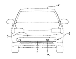
以下、本発明の車両用音出力装置の第1実施例を図1〜図6に基づいて説明する。図1〜図6に示す車両用音出力装置1は、車両2に取り付けられ、車両2外部に接近告知音(音)を放射することにより、歩行者などに車両2の接近を知らせる装置である。なお、以下、車両2の進行方向を前方向、後退方向を後方向とし、進行方向側を前面側、後退方向側を後面側と定義して説明する。 First Embodiment Hereinafter, a first embodiment of a vehicle sound output apparatus according to the present invention will be described with reference to FIGS. A
図2などに示すように、車両用音出力装置1は、車両2のフロントバンパを補強する補強部材としてのバンパリインフォース3と、スピーカ装置4と、バンパリインフォース3の後面側を覆い、バンパリインフォース3との間にスピーカ装置4の音道5(図4)を形成する音道部材6と、図示しないエアーシールと、を備えている。
As shown in FIG. 2 and the like, the vehicle
上記バンパリインフォース3は、金属板をプレス加工して設けられ、車両2の左右方向に長尺状に設けられている。このバンパリインフォース3は、衝撃吸収部材としてのバンパアブソーバ7(図1)の後面側に取り付けられている。このバンパリインフォース3には、図3、図4などに示すように、左右方向に長尺状のリインフォース本体部31と、リインフォース本体部31の上下方向両端から後方向に向かって立設したリインフォース側壁部32と、リインフォース側壁部32の端部から上下方向に立設したリインフォースフランジ部33と、を備え、後面側から見て長手方向に沿ったリインフォース凹部34が形成されている。
The
上記リインフォース本体部31の助手席側には、後述するスピーカ装置4から出力される接近告知音を放射する開口31Aが設けられている。このバンパリインフォース3の前面側に取り付けられるバンパアブソーバ7にも、図1に示すように、後述するスピーカ装置4から出力される接近告知音を放射する開口7Aが設けられている。このバンパアブソーバ7の開口7Aは、バンパリインフォース3の開口31Aに対向して設けられている。
An
上記スピーカ装置4は、接近告知音を出力するスピーカであり、例えば、接近告知音として車両2の駆動音を擬似的に発生する。このスピーカ装置4は、図4(B)に示すように、後述する音道部材6に取り付けられ、バンパリインフォース3と音道部材6との間に形成された音道5内に収容される。また、スピーカ装置4は、その正面がバンパリインフォース3やバンパアブソーバ7に設けた開口31A、開口7Aに対向するように設けられている。
The
上記音道部材6は、例えば樹脂などから構成され、バンパリインフォース3との間に左右方向に長尺状の音道5を形成する。音道部材6は、図4や図6などに示すように、リインフォース凹部34の後面側開口を覆う板状の音道部材本体部61と、音道5を上下に仕切る仕切壁62と、音道5の長手方向開口を塞ぐ第1の側壁部63及び第2の側壁部64と、スピーカ装置4を収容する収容部65と、蓋部66と、補強リブ67と、を有している。
The said
上記音道部材本体部61は、長尺の板状に形成されている。音道部材本体部61は、バンパリインフォース3の長手方向の長さよりも短く設けられ、バンパリインフォース3の助手席側に設けられている。仕切壁62は、音道部材本体部61から前面側に向かって立設し、音道部材本体部61の上下方向中央から長手方向に延在している。この仕切壁62により、音道5が上下に仕切られ、長手方向に直線状の第1、第2の直線部51A、51Bに仕切られる。
The sound path member
上記第1の側壁部63は、音道部材本体部61から前面側に向かって立設し、上下方向に延在している。また、第1の側壁部63は、仕切壁62よりもスピーカ装置4側(=助手席側)に離間して設けられている。この第1の側壁部63は、リインフォース凹部34に嵌め込まれることにより、音道5の長手方向助手席側の開口が塞がれる。
The
上記第2の側壁部64は、音道部材本体部61から前面側に向かって立設し、上下方向に延在している。この第2の側壁部64は、リインフォース凹部34に嵌め込まれることにより、音道5の長手方向のスピーカ装置4から離れた側(=運転席側)の開口が塞がれる。また、第2の側壁部64は仕切壁62の運転席側に離間して設けられ、これにより、第1の直線部51Aと第2の直線部51Bの長手方向運転席側が連通し、音道5を第1の直線部51Aから第2の直線部51Bに折り返す折返部52が形成される。なお、上記第1の直線部51A、第2の直線部51B、折返部52の断面積は略等しくなるように、仕切壁62、第2の側壁部64が設けられている。
The second
また、上記第2の側壁部64は、長手方向のスピーカ装置4から離れた側に凹む凹部64Aが形成され、その凹部64AにはRが付けられている。一方、この凹部64Aに対向する仕切壁62の端面にもRが付けられている。これにより、折返部52は、曲線に沿う。
The second
上記収容部65は、図4(B)に示すように、音道部材本体部61に設けたスピーカ装置4の取付孔61A周縁から前面側に立設した周壁65Aと、スピーカ装置4の振動板を露出する開口65Bと、を備えている。スピーカ装置4は、この周壁65Aに囲まれた空間に収容される。これにより、スピーカ装置4は、バンパリインフォース3と音道部材6との間の空間である音道5内に収容される。また、上記周壁65Aには、図5(A)に示すように、第1の直線部51Aと連通する開口65A−1が設けられている。
As shown in FIG. 4B, the
上記蓋部66は、板状に形成され、図4(B)に示すように、音道部材本体部61に設けた取付孔61Aを後面側から覆って塞ぐ。この蓋部66には、ネジ挿入孔66Aが設けられている。上記スピーカ装置4は、音道部材6の取付孔61Aから収容部65内に収容され、その後、取付孔61Aを塞ぐように蓋部66が配置される。次に、ネジNを蓋部66のネジ挿入孔66Aに挿入すると共に、スピーカ装置4に設けたネジ孔(図示せず)に螺合することにより、音道部材6にスピーカ装置4を取り付けることができる。
The
上記補強リブ67は、音道部材6を補強するためのリブであり、図6に示すように、音道部材本体部61から前面側に向かって突出して設けられ、長手方向に沿って延在する。上記補強リブ67は、仕切壁62の上下にそれぞれ設けられている。
The reinforcing
上記図示しないエアーシールは、バンパリインフォース3と音道部材6との間の隙間を塞ぐために設けられ、例えば仕切壁62とバンパリインフォース3との間や、第1の側壁部63及び第2の側壁部64とバンパリインフォース3との間に挟まれている。
The air seal (not shown) is provided to close the gap between the
次に、上述した構成の車両用音出力装置1を構成するスピーカ装置4から出力される音の放射について説明する。図4(B)に示すように、スピーカ装置4の前面から放射された音は、矢印Y1に示すように、バンパリインフォース3の開口31A及びバンパアブソーバ7の開口7Aから車両2の外部に放射される。一方、スピーカ装置4の後面から放射された音は、図5に示すように、矢印Y2に示すように、収容部65の開口65A−1を通って第1の直線部51Aに侵入し、第1の直線部51Aに沿って運転席側に向かって進み、スピーカ装置4から離れていく。その後、折返部52に沿って折返して、第2の直線部51Bに侵入し、第2の直線部51Bに沿って助手席側に向かって進み、スピーカ装置4側に戻ってくる。スピーカ装置4側に戻ってきた音は、バンパリインフォースの開口31A及びバンパアブソーバ7の開口7Aから車両2の外部に放射される。
Next, radiation of sound output from the
上述した実施例によれば、音道5に折返部52を設けることにより、バンパリインフォース3の長手方向の長さに制限されることなく、所望の長さの音道5を設けることができ、車両2の外部に存在する人に対してスピーカ装置4から出力された接近告知音を効果的に発することができる。
According to the embodiment described above, the
また、上述した実施例によれば、音道5が、折返部52を奇数個(上記実施例では1個)有している。これにより、音道5を通る音をスピーカ装置4側に戻すことができる。
Further, according to the above-described embodiment, the
また、上述した実施例によれば、スピーカ装置4の前面から放射される音は、バンパリインフォース3の前面の開口31Aから放射され、スピーカ装置4の後面から放射される音は、音道5を通りバンパリインフォース3の前面の開口31Aから放射される。これにより、スピーカ装置4の前面及び後面から放射される音を、1つの開口31Aから外部に出力できる。このとき、音道5の長さを調整して、開口31Aから出力されるスピーカ装置4の前面及び後面から放射される所望の周波数の音の音圧を大きくすることができ、どのリスニング位置からでも同じように聞こえることができる。
Further, according to the above-described embodiment, the sound radiated from the front surface of the
次に、本発明者らは、上述した車両用音出力装置1を製造して、図7に示すように、車両2に対して正面、左前45度、左90度でのスピーカ装置4の音圧と暗騒音との周波数特性を測定した。結果を図8に示す。同図からも明らかなように、リスニング位置が変わってもほぼ同じ周波数特性を得ることができ、どのリスニング位置からでも同じように聞こえることが確認できた。
Next, the present inventors manufactured the above-described vehicle
また、上述した実施例によれば、音道5の第1の直線部51A、第2の直線部51B及び折返部52の断面積が略等しい。これにより、スピーカ装置4から放射された音が音道5をスムーズに進むことができる。
Further, according to the above-described embodiment, the cross-sectional areas of the first
また、上述した実施例によれば、第2の側壁部64の凹部64Aと、この凹部64Aに対向する仕切壁62の端面にRを付けている。これにより、折返部52は、曲線に沿って設けられ、スピーカ装置4から放射された音がスムーズに折返部52で折り返される。
Moreover, according to the Example mentioned above, R is attached to the end surface of the recessed
なお、上述した第1実施例では、スピーカ装置4の後面から放射された音は、下側に設けられた第1の直線部51A、折返部52、第2の直線部51Bの順に音道5を通っていたが、本発明はこれに限ったものではない。上側の第2の直線部51B、折返部52、第1の直線部51Aの順に音道を通るようにしてもよい。
In the first embodiment described above, the sound radiated from the rear surface of the
また、上述した第1実施例では、音道部材6は、バンパリインフォース3の助手席側に取り付けられていたが、本発明はこれに限ったものではない。運転席側に取り付けられるようにしてもよい。また、国によっては運転席が右側または左側の場合があるが、本願の実施例においてはそのいずれかに限定するものではない。
In the first embodiment described above, the
また、上述した第1実施例では、スピーカ装置4は、音道部材6に取り付けられていたが、本発明はこれに限ったものではない。スピーカ装置4は、バンパリインフォース3に取り付けられるようにしてもよい。
In the first embodiment described above, the
第2実施例
次に、第2実施例について図9を参照して説明する。なお、図9(A)は音道部材6については、断面で示している。第2実施例で異なる点は、音道5の形状である。第1実施例では、折返部52を1箇所だけ設けていたが、第2実施例では、3箇所の第1〜第3の折返部52A〜52Cを設けている。 Second Embodiment Next, a second embodiment will be described with reference to FIG. In FIG. 9A, the
詳しくは、第1実施例では、仕切壁62を1つ設けていたが、第2実施例では、仕切壁62を3つ設けて、音道5を上下に4つに仕切る。これにより、音道5が長手方向に直線状の4つの第1〜第4直線部51A〜51Dに仕切られる。また、図9(A)に示すように、中央の仕切壁62は、第2の側壁部64に連なって設けられる。また、一番上と一番下の仕切壁62のスピーカ装置4側の端部を連結する第3の側壁部68Aが設けられている。中央の仕切壁62は、第3の側壁部68Aからは離間している。
Specifically, in the first embodiment, one
これにより、第1の折返部52Aは、第1の直線部51A及び第2の直線部51Bのスピーカ装置4から離れた側の端部を連通し、第2の折返部52Bは、第2の直線部51B及び第3の直線部51Cのスピーカ装置4側の端部を連通し、第3の折返部52Cは、第3の直線部51C及び第4の直線部51Dのスピーカ装置4から離れた側を連通する。
As a result, the first folded
以上の構成によれば、スピーカ装置4の後面から放音された音は、矢印に示すように、第1の直線部51A、第1の折返部52A、第2の直線部51B、第2の折返部52B、第3の直線部51C、第3の折返部52C、第4の直線部51Dの順に進んでバンパリインフォース3の開口31A及びバンパアブソーバ7の開口7Aから車両2の外部に放射される。よって、さらに音道5を長くすることができる。また、音道部材6の長さを短くして軽量化もしくはコストダウンを図ることができる。
According to the above configuration, the sound emitted from the rear surface of the
第3実施例
次に、第3実施例について図10を参照して説明する。第3実施例で異なる点は、音道5の形状である。第1の実施例では、折返部52を1箇所だけ設けていたが、第3実施例では、3箇所の第1〜第3の折返部52A〜52Cを設けている。また、第1実施例では、音道5を上下に2つの直線部に仕切られていたが、第3実施例では、上下方向及び前後方向に4つの第1〜第4直線部51A〜51Dに仕切っている。 Third Embodiment Next, a third embodiment will be described with reference to FIG. The difference in the third embodiment is the shape of the
詳しくは、第3実施例では、音道部材6は、音道部材本体部61から後面側に立設し、音道5を上下方向に仕切る第1の仕切壁62Aと、音道部材本体部61と平行に設けられ、音道5を前後方向に仕切る第2の仕切壁62Bと、を備えている。第2の仕切壁62Bは、第2の側壁部64からスピーカ装置4側に向かって立設し、第1の仕切壁62Aと交差する。第1の側壁部63は、この第2の仕切壁62Bとは離間して設けられている。
Specifically, in the third embodiment, the
これにより、図10(C)に示すように、第1の折返部52Aは、第1の直線部51A及び第2の直線部51Bのスピーカ装置4から離れた側の端部を連結し、第2の折返部52Bは、第2の直線部51B及び第3の直線部51Cのスピーカ装置4側の端部を連結し、第3の折返部52Cは、第3の直線部51C及び第4の直線部51Dのスピーカ装置4から離れた側を連通する。
Thus, as shown in FIG. 10C, the first folded
以上の構成によれば、スピーカ装置4の後面から放音された音は、図10(B)や図10(C)の矢印に示すように、前面、下側に設けられた第1の直線部51A、第1の折返部52A、前面、上側に設けられた第2の直線部51B、第2の折返部52B、後面、上側に設けられた第3の直線部51C、第3の折返部52C、後面、下側に設けられた第4の直線部51Dの順に進んでバンパリインフォース3の開口31A及びバンパアブソーバ7の開口7Aから車両2の外部に放射される。
According to the above configuration, the sound emitted from the rear surface of the
第4実施例
次に、第4実施例について図11を参照して説明する。第4実施例で異なる点は、音道5の形状である。第1実施例では、音道5を上下方向に2つの直線部に仕切っていたが、第4実施例では、前後方向に4つの第1〜第4の直線部51A〜51Dに仕切っている。詳しくは、第4実施例では、図11(B)に示すように、音道部材本体部61と平行に配置される3つの第2の仕切壁62Bを設けている。この第2の仕切壁62Bは、音道部材本体部61から前面側に向かって立設する一対の立壁69によって支持されている。Fourth Embodiment Next, a fourth embodiment will be described with reference to FIG. The difference in the fourth embodiment is the shape of the
前後方向中央の第2の仕切壁62Bは、第2の側壁部64からスピーカ装置4側に向かって立設している。前後の第2の仕切壁62Bは、その長手方向両端が第1、第2の側壁部63、64から離間して設けられている。また、前後の第2の仕切壁62Bのスピーカ装置4側の端部同士を連結する第4の側壁部68Bが設けられている。中央の第2の仕切壁62Bは、第4の側壁部68Bとは離間して設けられている。
The
これにより、第1の折返部52Aは、第1の直線部51A及び第2の直線部51Bのスピーカ装置4から離れた側の端部を連通し、第2の折返部52Bは、第2の直線部51B及び第3の直線部51Cのスピーカ装置4側の端部を連通し、第3の折返部52Cは、第3の直線部51C及び第4の直線部51Dのスピーカ装置4から離れた側を連通する。
As a result, the first folded
この場合も、スピーカ装置4の後面から放音された音は、図10(B)や図10(C)の矢印に示すように、第1の直線部51A、第1の折返部52A、第2の直線部51B、第2の折返部52B、第3の直線部51C、第3の折返部52C、第4の直線部51Dの順に進んでバンパリインフォース3の開口31A及びバンパアブソーバ7の開口7Aから車両2の外部に放射される。
Also in this case, the sound emitted from the rear surface of the
なお、上述した実施例では、折返部52を奇数個設けて、スピーカ装置4の前面及び後面から出力される音を、バンパリインフォース3の前面に設けた1つの開口31Aから放射していたが、本発明はこれに限ったものではない。折返部52としては、偶数個設けて、スピーカ装置4の前面及び後面から出力される音を別々の開口から放射するような構造にしてもよい。
In the above-described embodiment, an odd number of
また、上述した実施例では、スピーカ装置4から出力される音は、バンパリインフォース3の前面に設けた開口31Aから放射していたが、本発明はこれに限ったものではない。音道5の長手方向の開口から放音するようにしてもよい。
In the above-described embodiment, the sound output from the
また、上述した実施例では、バンパリインフォース3は、フロントバンパを補強するためのものであって、リアバンパを補強するためのものであってもよい。
Further, in the above-described embodiment, the
また、前述した実施例は本発明の代表的な形態を示したに過ぎず、本発明は、実施形態に限定されるものではない。即ち、本発明の骨子を逸脱しない範囲で種々変形して実施することができる。 Further, the above-described embodiments are merely representative forms of the present invention, and the present invention is not limited to the embodiments. That is, various modifications can be made without departing from the scope of the present invention.
1 車両用音出力装置
2 車両
3 バンパリインフォース(補強部材)
4 スピーカ装置
5 音道
6 音道部材
51A 第1の直線部(直線部)
51B 第2の直線部(直線部)
51C 第3の直線部(直線部)
51D 第4の直線部(直線部)
52 折返部
52A 折返部
52B 折返部
52C 折返部
31A 開口DESCRIPTION OF
4
51B Second straight line part (straight line part)
51C Third straight part (straight part)
51D 4th straight line part (straight line part)
52
Claims (6)
前記補強部材との間に音道を形成する音道部材と、
前記音道内に収容されるスピーカ装置と、を備え、
前記音道が折返部を有するように、前記音道部材が設けられており、
前記スピーカ装置の前面から放射される音は、前記開口から放射され、
前記スピーカ装置の後面から放射される音は、前記音道を通り前記開口から放射されることを特徴とする車両用音出力装置。 Reinforcing the bumper of the vehicle, and a reinforcing member that have a opening to the front,
A sound path member forming the sound path between the reinforcing member,
A speaker device housed in the sound path,
The sound path member is provided so that the sound path has a folded portion ,
Sound radiated from the front surface of the speaker device is radiated from the opening,
A sound output device for a vehicle , wherein sound radiated from a rear surface of the speaker device is radiated from the opening through the sound path .
ことを特徴とする請求項1に記載の車両用音出力装置。 The vehicle sound output device according to claim 1, wherein the sound path includes an odd number of the folded portions.
前記折返部と前記直線部との断面積は略等しいことを特徴とする請求項1に記載の車両用音出力装置。 The sound path member is provided such that the sound path has a straight portion,
The vehicle sound output device according to claim 1 , wherein cross-sectional areas of the folded portion and the straight portion are substantially equal.
Applications Claiming Priority (1)
| Application Number | Priority Date | Filing Date | Title |
|---|---|---|---|
| PCT/JP2013/059975 WO2014162474A1 (en) | 2013-04-01 | 2013-04-01 | Sound output device for vehicle |
Publications (2)
| Publication Number | Publication Date |
|---|---|
| JPWO2014162474A1 JPWO2014162474A1 (en) | 2017-02-16 |
| JP6088043B2 true JP6088043B2 (en) | 2017-03-01 |
Family
ID=51657807
Family Applications (1)
| Application Number | Title | Priority Date | Filing Date |
|---|---|---|---|
| JP2015509727A Active JP6088043B2 (en) | 2013-04-01 | 2013-04-01 | Vehicle sound output device |
Country Status (3)
| Country | Link |
|---|---|
| US (1) | US9764687B2 (en) |
| JP (1) | JP6088043B2 (en) |
| WO (1) | WO2014162474A1 (en) |
Families Citing this family (8)
| Publication number | Priority date | Publication date | Assignee | Title |
|---|---|---|---|---|
| TWI583202B (en) * | 2015-11-03 | 2017-05-11 | 宏碁股份有限公司 | Electronic device |
| KR102383224B1 (en) * | 2016-12-06 | 2022-04-05 | 현대자동차 주식회사 | Structure for decreasing hydrogen concentration of fuel cell system |
| USD838634S1 (en) * | 2017-04-10 | 2019-01-22 | Volvo Lastvagnar Ab | Bumper component |
| USD834470S1 (en) * | 2017-04-10 | 2018-11-27 | Volvo Lastvagnar Ab | Bumper component |
| US11627394B2 (en) * | 2019-12-31 | 2023-04-11 | Harman International Industries, Incorporated | Loudspeaker assembly for providing audio external to a vehicle |
| KR102769946B1 (en) * | 2020-08-03 | 2025-02-18 | 현대자동차주식회사 | Electronic sound generator mounting structure for vehicle |
| DE102022128735A1 (en) * | 2022-10-28 | 2024-05-08 | Dr. Ing. H.C. F. Porsche Aktiengesellschaft | Bumper body part arrangement and a motor vehicle |
| JP2025029892A (en) * | 2023-08-22 | 2025-03-07 | トヨタ自動車株式会社 | Vehicle approach notification device |
Family Cites Families (6)
| Publication number | Priority date | Publication date | Assignee | Title |
|---|---|---|---|---|
| JPH059969Y2 (en) * | 1986-05-19 | 1993-03-11 | ||
| JPH0335840U (en) * | 1989-08-10 | 1991-04-08 | ||
| JP2008168676A (en) | 2007-01-09 | 2008-07-24 | Toyota Motor Corp | Vehicle approach notification device |
| US8204245B2 (en) * | 2007-10-31 | 2012-06-19 | Lund Industries, Inc. | Bumper with speaker |
| WO2011141982A1 (en) * | 2010-05-10 | 2011-11-17 | パイオニア株式会社 | Sound output device and sound output method |
| JP2013244895A (en) * | 2012-05-28 | 2013-12-09 | Denso Corp | Vehicle approach notification unit |
-
2013
- 2013-04-01 WO PCT/JP2013/059975 patent/WO2014162474A1/en not_active Ceased
- 2013-04-01 JP JP2015509727A patent/JP6088043B2/en active Active
- 2013-04-01 US US14/781,345 patent/US9764687B2/en not_active Expired - Fee Related
Also Published As
| Publication number | Publication date |
|---|---|
| WO2014162474A1 (en) | 2014-10-09 |
| JPWO2014162474A1 (en) | 2017-02-16 |
| US20160052449A1 (en) | 2016-02-25 |
| US9764687B2 (en) | 2017-09-19 |
Similar Documents
| Publication | Publication Date | Title |
|---|---|---|
| JP6088043B2 (en) | Vehicle sound output device | |
| CN101258051B (en) | Loudspeaker system for a motor vehicle utilizing a cavity formed by a support structure | |
| US11712996B2 (en) | Sound-producing device for vehicle | |
| JP6922388B2 (en) | Battery-equipped vehicle | |
| US10717469B2 (en) | Vehicle body front part structure | |
| JP6182596B2 (en) | Vehicle sound output device | |
| JP6148134B2 (en) | Car body floor panel structure | |
| WO2011145404A1 (en) | Vehicle rear outlet structure | |
| JP2017116706A (en) | Resonant sound absorbing structure | |
| US10322622B2 (en) | Vehicular door structure | |
| US20180244212A1 (en) | Speaker system for mobile object | |
| JP2014104805A (en) | Vehicle bumper including pedestrian collision detection device | |
| JP6079712B2 (en) | Bumper for vehicle | |
| JP2020062958A (en) | Vehicle approach notification device | |
| US10486614B2 (en) | Speaker system for mobile object | |
| KR101198603B1 (en) | Crash box in automotive bumper system | |
| JP2021054387A (en) | Vehicle structure | |
| US11648892B2 (en) | Noise reflector, fender liner, and silencing method | |
| JP6033705B2 (en) | Car rear floor structure | |
| JP2011132913A (en) | Air intake duct | |
| JP5513941B2 (en) | Horn speaker for vehicle installation | |
| JP2014180940A (en) | Undercover for vehicle | |
| JP7306211B2 (en) | vehicle front structure | |
| JP2012066654A (en) | Lower back structure for automobile | |
| JP6322390B2 (en) | Car speaker system |
Legal Events
| Date | Code | Title | Description |
|---|---|---|---|
| TRDD | Decision of grant or rejection written | ||
| A01 | Written decision to grant a patent or to grant a registration (utility model) |
Free format text: JAPANESE INTERMEDIATE CODE: A01 Effective date: 20170110 |
|
| A61 | First payment of annual fees (during grant procedure) |
Free format text: JAPANESE INTERMEDIATE CODE: A61 Effective date: 20170202 |
|
| R150 | Certificate of patent or registration of utility model |
Ref document number: 6088043 Country of ref document: JP Free format text: JAPANESE INTERMEDIATE CODE: R150 |