JP6085256B2 - Process of local repair of damaged thermomechanical parts and parts repaired according to the process, in particular turbine parts - Google Patents
Process of local repair of damaged thermomechanical parts and parts repaired according to the process, in particular turbine parts Download PDFInfo
- Publication number
- JP6085256B2 JP6085256B2 JP2013557155A JP2013557155A JP6085256B2 JP 6085256 B2 JP6085256 B2 JP 6085256B2 JP 2013557155 A JP2013557155 A JP 2013557155A JP 2013557155 A JP2013557155 A JP 2013557155A JP 6085256 B2 JP6085256 B2 JP 6085256B2
- Authority
- JP
- Japan
- Prior art keywords
- repaired
- brazing
- preform
- repair
- temperature
- Prior art date
- Legal status (The legal status is an assumption and is not a legal conclusion. Google has not performed a legal analysis and makes no representation as to the accuracy of the status listed.)
- Active
Links
- 238000000034 method Methods 0.000 title claims description 20
- 230000008439 repair process Effects 0.000 title claims description 18
- 230000008569 process Effects 0.000 title claims description 12
- 230000000930 thermomechanical effect Effects 0.000 title claims description 7
- 238000005219 brazing Methods 0.000 claims description 32
- 239000010410 layer Substances 0.000 claims description 29
- 238000005245 sintering Methods 0.000 claims description 23
- 229910000601 superalloy Inorganic materials 0.000 claims description 18
- 239000000203 mixture Substances 0.000 claims description 17
- 239000000843 powder Substances 0.000 claims description 14
- 239000000463 material Substances 0.000 claims description 13
- 238000009792 diffusion process Methods 0.000 claims description 11
- 229910045601 alloy Inorganic materials 0.000 claims description 9
- 239000000956 alloy Substances 0.000 claims description 9
- 230000004888 barrier function Effects 0.000 claims description 8
- 229910052751 metal Inorganic materials 0.000 claims description 7
- 239000002184 metal Substances 0.000 claims description 7
- 239000011241 protective layer Substances 0.000 claims description 7
- 230000008018 melting Effects 0.000 claims description 5
- 238000002844 melting Methods 0.000 claims description 5
- 238000002360 preparation method Methods 0.000 claims description 4
- 229910001233 yttria-stabilized zirconia Inorganic materials 0.000 claims description 4
- 238000010438 heat treatment Methods 0.000 claims description 3
- 229910052697 platinum Inorganic materials 0.000 claims description 3
- 229910052709 silver Inorganic materials 0.000 claims description 3
- 229910018580 Al—Zr Inorganic materials 0.000 claims description 2
- 229910003310 Ni-Al Inorganic materials 0.000 claims description 2
- 229910052802 copper Inorganic materials 0.000 claims description 2
- 229910052735 hafnium Inorganic materials 0.000 claims description 2
- 229910052759 nickel Inorganic materials 0.000 claims description 2
- 229910052710 silicon Inorganic materials 0.000 claims description 2
- 229910052727 yttrium Inorganic materials 0.000 claims description 2
- 241000287463 Phalacrocorax Species 0.000 claims 1
- 239000000853 adhesive Substances 0.000 claims 1
- 230000001070 adhesive effect Effects 0.000 claims 1
- 238000001914 filtration Methods 0.000 claims 1
- 239000002023 wood Substances 0.000 claims 1
- 238000002490 spark plasma sintering Methods 0.000 description 8
- 238000004519 manufacturing process Methods 0.000 description 3
- BASFCYQUMIYNBI-UHFFFAOYSA-N platinum Substances [Pt] BASFCYQUMIYNBI-UHFFFAOYSA-N 0.000 description 3
- OKTJSMMVPCPJKN-UHFFFAOYSA-N Carbon Chemical compound [C] OKTJSMMVPCPJKN-UHFFFAOYSA-N 0.000 description 2
- 229910052782 aluminium Inorganic materials 0.000 description 2
- 230000015572 biosynthetic process Effects 0.000 description 2
- 239000000919 ceramic Substances 0.000 description 2
- 238000005260 corrosion Methods 0.000 description 2
- 230000007797 corrosion Effects 0.000 description 2
- 238000005516 engineering process Methods 0.000 description 2
- 229910002804 graphite Inorganic materials 0.000 description 2
- 239000010439 graphite Substances 0.000 description 2
- BQCADISMDOOEFD-UHFFFAOYSA-N Silver Chemical compound [Ag] BQCADISMDOOEFD-UHFFFAOYSA-N 0.000 description 1
- 230000002411 adverse Effects 0.000 description 1
- 238000005054 agglomeration Methods 0.000 description 1
- 230000002776 aggregation Effects 0.000 description 1
- XAGFODPZIPBFFR-UHFFFAOYSA-N aluminium Chemical compound [Al] XAGFODPZIPBFFR-UHFFFAOYSA-N 0.000 description 1
- 229910010293 ceramic material Inorganic materials 0.000 description 1
- 238000004140 cleaning Methods 0.000 description 1
- 238000005056 compaction Methods 0.000 description 1
- 230000000295 complement effect Effects 0.000 description 1
- 230000006835 compression Effects 0.000 description 1
- 238000007906 compression Methods 0.000 description 1
- 230000008021 deposition Effects 0.000 description 1
- 230000003628 erosive effect Effects 0.000 description 1
- 239000000374 eutectic mixture Substances 0.000 description 1
- 238000010304 firing Methods 0.000 description 1
- 229910001938 gadolinium oxide Inorganic materials 0.000 description 1
- 229940075613 gadolinium oxide Drugs 0.000 description 1
- CMIHHWBVHJVIGI-UHFFFAOYSA-N gadolinium(iii) oxide Chemical compound [O-2].[O-2].[O-2].[Gd+3].[Gd+3] CMIHHWBVHJVIGI-UHFFFAOYSA-N 0.000 description 1
- 238000007373 indentation Methods 0.000 description 1
- 238000003754 machining Methods 0.000 description 1
- 229910044991 metal oxide Inorganic materials 0.000 description 1
- 150000004706 metal oxides Chemical class 0.000 description 1
- 239000002086 nanomaterial Substances 0.000 description 1
- 230000003647 oxidation Effects 0.000 description 1
- 238000007254 oxidation reaction Methods 0.000 description 1
- 230000036961 partial effect Effects 0.000 description 1
- 239000002245 particle Substances 0.000 description 1
- 238000004663 powder metallurgy Methods 0.000 description 1
- 238000003825 pressing Methods 0.000 description 1
- 230000001681 protective effect Effects 0.000 description 1
- 230000002829 reductive effect Effects 0.000 description 1
- 239000011819 refractory material Substances 0.000 description 1
- 239000004332 silver Substances 0.000 description 1
- 239000011343 solid material Substances 0.000 description 1
- 238000003786 synthesis reaction Methods 0.000 description 1
- XLYOFNOQVPJJNP-UHFFFAOYSA-N water Substances O XLYOFNOQVPJJNP-UHFFFAOYSA-N 0.000 description 1
- 238000003466 welding Methods 0.000 description 1
- 229910052726 zirconium Inorganic materials 0.000 description 1
Images


Classifications
-
- B—PERFORMING OPERATIONS; TRANSPORTING
- B22—CASTING; POWDER METALLURGY
- B22F—WORKING METALLIC POWDER; MANUFACTURE OF ARTICLES FROM METALLIC POWDER; MAKING METALLIC POWDER; APPARATUS OR DEVICES SPECIALLY ADAPTED FOR METALLIC POWDER
- B22F7/00—Manufacture of composite layers, workpieces, or articles, comprising metallic powder, by sintering the powder, with or without compacting wherein at least one part is obtained by sintering or compression
- B22F7/02—Manufacture of composite layers, workpieces, or articles, comprising metallic powder, by sintering the powder, with or without compacting wherein at least one part is obtained by sintering or compression of composite layers
- B22F7/04—Manufacture of composite layers, workpieces, or articles, comprising metallic powder, by sintering the powder, with or without compacting wherein at least one part is obtained by sintering or compression of composite layers with one or more layers not made from powder, e.g. made from solid metal
-
- B—PERFORMING OPERATIONS; TRANSPORTING
- B22—CASTING; POWDER METALLURGY
- B22F—WORKING METALLIC POWDER; MANUFACTURE OF ARTICLES FROM METALLIC POWDER; MAKING METALLIC POWDER; APPARATUS OR DEVICES SPECIALLY ADAPTED FOR METALLIC POWDER
- B22F3/00—Manufacture of workpieces or articles from metallic powder characterised by the manner of compacting or sintering; Apparatus specially adapted therefor ; Presses and furnaces
- B22F3/10—Sintering only
- B22F3/105—Sintering only by using electric current other than for infrared radiant energy, laser radiation or plasma ; by ultrasonic bonding
-
- B—PERFORMING OPERATIONS; TRANSPORTING
- B22—CASTING; POWDER METALLURGY
- B22F—WORKING METALLIC POWDER; MANUFACTURE OF ARTICLES FROM METALLIC POWDER; MAKING METALLIC POWDER; APPARATUS OR DEVICES SPECIALLY ADAPTED FOR METALLIC POWDER
- B22F5/00—Manufacture of workpieces or articles from metallic powder characterised by the special shape of the product
- B22F5/009—Manufacture of workpieces or articles from metallic powder characterised by the special shape of the product of turbine components other than turbine blades
-
- B—PERFORMING OPERATIONS; TRANSPORTING
- B22—CASTING; POWDER METALLURGY
- B22F—WORKING METALLIC POWDER; MANUFACTURE OF ARTICLES FROM METALLIC POWDER; MAKING METALLIC POWDER; APPARATUS OR DEVICES SPECIALLY ADAPTED FOR METALLIC POWDER
- B22F5/00—Manufacture of workpieces or articles from metallic powder characterised by the special shape of the product
- B22F5/04—Manufacture of workpieces or articles from metallic powder characterised by the special shape of the product of turbine blades
-
- B—PERFORMING OPERATIONS; TRANSPORTING
- B22—CASTING; POWDER METALLURGY
- B22F—WORKING METALLIC POWDER; MANUFACTURE OF ARTICLES FROM METALLIC POWDER; MAKING METALLIC POWDER; APPARATUS OR DEVICES SPECIALLY ADAPTED FOR METALLIC POWDER
- B22F7/00—Manufacture of composite layers, workpieces, or articles, comprising metallic powder, by sintering the powder, with or without compacting wherein at least one part is obtained by sintering or compression
- B22F7/06—Manufacture of composite layers, workpieces, or articles, comprising metallic powder, by sintering the powder, with or without compacting wherein at least one part is obtained by sintering or compression of composite workpieces or articles from parts, e.g. to form tipped tools
- B22F7/062—Manufacture of composite layers, workpieces, or articles, comprising metallic powder, by sintering the powder, with or without compacting wherein at least one part is obtained by sintering or compression of composite workpieces or articles from parts, e.g. to form tipped tools involving the connection or repairing of preformed parts
- B22F7/064—Manufacture of composite layers, workpieces, or articles, comprising metallic powder, by sintering the powder, with or without compacting wherein at least one part is obtained by sintering or compression of composite workpieces or articles from parts, e.g. to form tipped tools involving the connection or repairing of preformed parts using an intermediate powder layer
-
- B—PERFORMING OPERATIONS; TRANSPORTING
- B22—CASTING; POWDER METALLURGY
- B22F—WORKING METALLIC POWDER; MANUFACTURE OF ARTICLES FROM METALLIC POWDER; MAKING METALLIC POWDER; APPARATUS OR DEVICES SPECIALLY ADAPTED FOR METALLIC POWDER
- B22F7/00—Manufacture of composite layers, workpieces, or articles, comprising metallic powder, by sintering the powder, with or without compacting wherein at least one part is obtained by sintering or compression
- B22F7/06—Manufacture of composite layers, workpieces, or articles, comprising metallic powder, by sintering the powder, with or without compacting wherein at least one part is obtained by sintering or compression of composite workpieces or articles from parts, e.g. to form tipped tools
- B22F7/08—Manufacture of composite layers, workpieces, or articles, comprising metallic powder, by sintering the powder, with or without compacting wherein at least one part is obtained by sintering or compression of composite workpieces or articles from parts, e.g. to form tipped tools with one or more parts not made from powder
-
- B—PERFORMING OPERATIONS; TRANSPORTING
- B23—MACHINE TOOLS; METAL-WORKING NOT OTHERWISE PROVIDED FOR
- B23P—METAL-WORKING NOT OTHERWISE PROVIDED FOR; COMBINED OPERATIONS; UNIVERSAL MACHINE TOOLS
- B23P6/00—Restoring or reconditioning objects
- B23P6/002—Repairing turbine components, e.g. moving or stationary blades, rotors
- B23P6/007—Repairing turbine components, e.g. moving or stationary blades, rotors using only additive methods, e.g. build-up welding
-
- B—PERFORMING OPERATIONS; TRANSPORTING
- B22—CASTING; POWDER METALLURGY
- B22F—WORKING METALLIC POWDER; MANUFACTURE OF ARTICLES FROM METALLIC POWDER; MAKING METALLIC POWDER; APPARATUS OR DEVICES SPECIALLY ADAPTED FOR METALLIC POWDER
- B22F3/00—Manufacture of workpieces or articles from metallic powder characterised by the manner of compacting or sintering; Apparatus specially adapted therefor ; Presses and furnaces
- B22F3/10—Sintering only
- B22F3/105—Sintering only by using electric current other than for infrared radiant energy, laser radiation or plasma ; by ultrasonic bonding
- B22F2003/1051—Sintering only by using electric current other than for infrared radiant energy, laser radiation or plasma ; by ultrasonic bonding by electric discharge
-
- B—PERFORMING OPERATIONS; TRANSPORTING
- B22—CASTING; POWDER METALLURGY
- B22F—WORKING METALLIC POWDER; MANUFACTURE OF ARTICLES FROM METALLIC POWDER; MAKING METALLIC POWDER; APPARATUS OR DEVICES SPECIALLY ADAPTED FOR METALLIC POWDER
- B22F2999/00—Aspects linked to processes or compositions used in powder metallurgy
-
- Y—GENERAL TAGGING OF NEW TECHNOLOGICAL DEVELOPMENTS; GENERAL TAGGING OF CROSS-SECTIONAL TECHNOLOGIES SPANNING OVER SEVERAL SECTIONS OF THE IPC; TECHNICAL SUBJECTS COVERED BY FORMER USPC CROSS-REFERENCE ART COLLECTIONS [XRACs] AND DIGESTS
- Y10—TECHNICAL SUBJECTS COVERED BY FORMER USPC
- Y10T—TECHNICAL SUBJECTS COVERED BY FORMER US CLASSIFICATION
- Y10T29/00—Metal working
- Y10T29/49—Method of mechanical manufacture
- Y10T29/49316—Impeller making
- Y10T29/49318—Repairing or disassembling
-
- Y—GENERAL TAGGING OF NEW TECHNOLOGICAL DEVELOPMENTS; GENERAL TAGGING OF CROSS-SECTIONAL TECHNOLOGIES SPANNING OVER SEVERAL SECTIONS OF THE IPC; TECHNICAL SUBJECTS COVERED BY FORMER USPC CROSS-REFERENCE ART COLLECTIONS [XRACs] AND DIGESTS
- Y10—TECHNICAL SUBJECTS COVERED BY FORMER USPC
- Y10T—TECHNICAL SUBJECTS COVERED BY FORMER US CLASSIFICATION
- Y10T428/00—Stock material or miscellaneous articles
- Y10T428/12—All metal or with adjacent metals
- Y10T428/12014—All metal or with adjacent metals having metal particles
- Y10T428/12021—All metal or with adjacent metals having metal particles having composition or density gradient or differential porosity
Description
本発明は、使用中に、例えば、腐食、浸食、または摩耗により、かなりの応力を受けた損傷熱機械的部品の局部補修のプロセスに関する。本発明は、さらに、このプロセスに従って補修された部品に関し、本発明は、特に、タービン部品に適用されるが、これに限定されない。 The present invention relates to the process of local repair of damaged thermomechanical parts that have undergone considerable stress during use, for example, due to corrosion, erosion, or wear. The invention further relates to a part repaired according to this process, and the invention applies in particular to, but not limited to, turbine parts.
本発明の分野は、ニッケル基超合金耐火材料の分野である。これらの材料は、熱機械的部品、特に、航空宇宙分野のガスタービン部品、例えば、特に、腐食および酸化に耐えられ可動整流羽根もしくは分配羽根、これらの羽根のプラットフォーム、基部、または、他の機器を構成することができる。 The field of the invention is that of nickel-base superalloy refractory materials. These materials are thermomechanical components, especially gas turbine components in the aerospace field, such as movable rectifying or distributing blades that are particularly resistant to corrosion and oxidation, platforms, bases, or other equipment of these blades. Can be configured.
しかしながら、これらの部品は、圧力応力および温度応力を受けることで材料が欠損するので、材料を追加して補修する必要がある。この補修は、同じタイプまたは化学的に類似した組成の構成材料を維持しながら、部品を元の寸法に復元することから成る。 However, these parts are damaged when subjected to pressure stress and temperature stress. Therefore, it is necessary to repair the parts by adding materials. This repair consists of restoring the part to its original dimensions while maintaining the same type or composition of chemically similar composition.
そのために、補修が重要性が低いおよび範囲が限定的な、部品の領域に限定される場合には、アーク溶接によって局部補修することが知られている。 For this reason, it is known to repair locally by arc welding when repair is limited to parts areas where the importance is low and the scope is limited.
広範囲または重要性の高い補修に対する1つの解決策は、固体状の材料を補修される領域に追加することから成る。この場合、材料は、特別な炉内で高温にされた超合金粉末とろう付け用粉末の混合物から成るプレートもしくはストリップから切断されたプリフォームとして利用される。したがって、この混合物は、粉末の混合物によって作られた低融点共晶混合物であるので、焼結される。このようにして得られた焼結物は、その後、洗浄された補修される部品の領域に沿って配置されて、全体が高温にされる。次いで、拡散ろう付けのプロセスが行われ、焼結物が部品の表面にろう付けされる。 One solution for extensive or critical repairs consists of adding solid material to the area to be repaired. In this case, the material is used as a preform cut from a plate or strip of a mixture of superalloy powder and brazing powder that has been heated to high temperature in a special furnace. This mixture is therefore sintered because it is a low melting eutectic mixture made by a mixture of powders. The sintered product obtained in this way is then placed along the region of the cleaned part to be repaired and brought to a high temperature as a whole. A diffusion brazing process is then performed and the sintered product is brazed to the surface of the part.
この方法では、ウォータージェットを使用して焼結シートが切断されて平面的な2次元(2D)プリフォームが作製される。ろう付け後、部品は、元の形状に近い形状に復元して適切な空気力学特性を付与するために、平面領域を機械加工することによって成形される。 In this method, the sintered sheet is cut using a water jet to produce a planar two-dimensional (2D) preform. After brazing, the part is molded by machining the planar area to restore a shape close to the original shape and impart appropriate aerodynamic properties.
このプロセスでは、ろう付け用粉末、したがって、溶融成分が焼結物の厚さ全体にわたって分布していることが必要となる。しかしながら、溶融成分の存在は、熱機械特性に悪影響をもたらす。 This process requires that the brazing powder, and thus the molten component, be distributed throughout the thickness of the sinter. However, the presence of the molten component adversely affects thermomechanical properties.
また、焼結物のゾーンに関係なく、一定の厚さの2次元の焼結プリフォームしか作製することができない。しかしながら、対象となる部品の近年使用されている種類では、特定のゾーンで厚さが異なる焼結物を使用するのが有利である。現行の方法では、このような精密さを実現することができない。 In addition, only a two-dimensional sintered preform having a constant thickness can be produced regardless of the zone of the sintered product. However, for the recently used types of parts of interest, it is advantageous to use sinters with different thicknesses in specific zones. Such precision cannot be achieved with current methods.
さらに、焼結物の生成は、複数の連続するステップによって行われるので、製造コストが高くなる。また、材料の広範囲の部分が欠損するので、焼結物はシートから作製されるが、シートの大部分は廃棄される。 Furthermore, since the production | generation of a sintered compact is performed by several continuous steps, manufacturing cost becomes high. In addition, since a large portion of the material is lost, the sintered product is made from the sheet, but most of the sheet is discarded.
本発明の目的は、元の部品の形状にほぼ類似した形状の精密な3次元(3D)焼結物の簡単、迅速、かつ効率的な製造を提案することによって、先行技術の不利点を克服することである。そのために、本発明は、スパークプラズマ焼結(SPS)技術によるフラッシュ焼結を使用する。 The object of the present invention is to overcome the disadvantages of the prior art by proposing simple, rapid and efficient production of precise three-dimensional (3D) sintered products of a shape approximately similar to the shape of the original part. It is to be. To that end, the present invention uses flash sintering by spark plasma sintering (SPS) technology.
SPS技術は、高い一軸圧力の印加と高い直流パルスの印加とを同時に組み合わせて、ほぼ即座に均一に温度を上昇させるものである。この技術は、粉末治金の分野では既知の技術であり、凝集と圧密とによって粉末から金属部品もしくは金属酸化物を製造することができる。特に、SPSフラッシュ技術を使用することにより、制御することができる特定の微細構造を有する部品を製造することができる。 In the SPS technique, a high uniaxial pressure application and a high DC pulse application are simultaneously combined to increase the temperature almost immediately and uniformly. This technique is a known technique in the field of powder metallurgy, and a metal part or metal oxide can be produced from powder by agglomeration and compaction. In particular, by using SPS flash technology, parts with a specific microstructure that can be controlled can be produced.
より詳細には、本発明の主題は、超合金製の熱機械的部品の局部補修のプロセスである。本発明のプロセスは、準備ステップにおいて、SPSフラッシュ焼結用のエンクロージャダイ内で損傷部品の少なくとも補修部分に対応するくぼみの形状であるモールドを作製すること、モールドに多層構造を形成する少なくとも1つのろう付け用粉末層と少なくとも1つの超合金基粉末層とを導入することから成る。その後の焼結ステップにおいて、材料と部品との接着部が拡散によって後で形成されるように、温度、圧力、および継続時間が少なくとも1つのプラトー温度および少なくとも1つのプラトー圧力によって調節されたフラッシュ焼結サイクルに従って加圧しパルス電流を通電することにより温度を急上昇させることから成る。この焼結ステップにより、多層構造内に組成勾配が形成されたプリフォームであって、補修される部品に接合されるろう付け面と超合金材料(6s)がプリフォームの表面に現れたプリフォームが作製される。 More particularly, the subject of the present invention is the process of local repair of thermomechanical parts made of superalloys. In the preparation step, the process of the present invention creates a mold that is in the shape of a recess corresponding to at least a repaired part of a damaged part in an enclosure die for SPS flash sintering, and forms at least one multilayer structure in the mold. And introducing a brazing powder layer and at least one superalloy-based powder layer. In a subsequent sintering step, flash firing in which the temperature, pressure, and duration are adjusted by at least one plateau temperature and at least one plateau pressure so that the bond between the material and the part is later formed by diffusion. It consists of rapidly increasing the temperature by applying pressure and applying a pulse current according to the connection cycle. Preform in which a composition gradient is formed in the multilayer structure by this sintering step, wherein the brazing surface to be joined to the part to be repaired and the superalloy material (6s) appear on the surface of the preform. Is produced.
有利には、フラッシュ焼結サイクルの温度、圧力、および継続時間は、少なくとも600℃/分の温度上昇、約1000℃から2000℃の範囲のプラトー温度、約10Mpaから100Mpaの範囲のプラトー圧力で調節される。 Advantageously, the temperature, pressure, and duration of the flash sintering cycle are adjusted with a temperature increase of at least 600 ° C./min, a plateau temperature in the range of about 1000 ° C. to 2000 ° C., and a plateau pressure in the range of about 10 Mpa to 100 Mpa. Is done.
一実施形態によれば、モールドは、元の部品全体に対応するくぼみと一致する形状を有する。焼結ステップ中に、超合金層は、拡散によって、材料と補修される部品とを連続的に接着する。 According to one embodiment, the mold has a shape that matches a recess corresponding to the entire original part. During the sintering step, the superalloy layer continuously bonds the material and the part to be repaired by diffusion.
次のろう付けステップにおいて、このようにして作製されたプリフォームのろう付け面が、補修される部品の領域と接触した状態で配置されることができる。次いで、適切な炉内で、プリフォームとそれに沿って配置された部品とを少なくともろう付け用合金の溶融温度に等しい温度になるまで加熱することによって、補修される部品内にろう付け用合金の溶融成分が拡散することで、ろう付け面が接着される。したがって、補修領域における部品の機械的脆弱部が著しく低減され、あるいは解消される。 In the next brazing step, the brazing surface of the preform thus produced can be placed in contact with the area of the part to be repaired. The brazing alloy is then placed in the part to be repaired in a suitable furnace by heating the preform and the parts disposed along it to a temperature at least equal to the melting temperature of the brazing alloy. The brazing surface is bonded by the diffusion of the molten component. Therefore, mechanical weak parts of the parts in the repair area are significantly reduced or eliminated.
次のろう付けステップにおいて、このようにして作製されたプリフォームのろう付け面は、補修される部品の領域と接触した状態で配置される。次いで、適切な炉内で、プリフォームとそれに沿って配置された部品とを少なくともろう付け用合金の溶融温度に等しい温度になるまで加熱することによって、補修される部品内にろう付け用合金の溶融成分が拡散することによって、ろう付け面が接着される。 In the next brazing step, the brazing surface of the preform thus produced is placed in contact with the area of the part to be repaired. The brazing alloy is then placed in the part to be repaired in a suitable furnace by heating the preform and the parts disposed along it to a temperature at least equal to the melting temperature of the brazing alloy. The brazing surface is bonded by the diffusion of the molten component.
特定の実施形態では、
準備段階で、金属保護層および熱バリア層が超合金層の上に堆積され、
金属保護層は、Ni、Pt、Hf、Y、Zr、Al、Si、Cu、Ag、ならびに/もしくはAu、および/またはNi−Al組成物、Ni−Pt−Al組成物、ならびに/もしくはNi−Al−Zr組成物から成る少なくとも1つのシートダイで構成され、
熱バリア層は、6から8%重量のイットリア安定化ジルコニア(熱バリア組成物ZrO2−6‐8Y2O3)で構成される。
In certain embodiments,
In the preparatory stage, a metal protective layer and a thermal barrier layer are deposited on the superalloy layer,
The metal protective layer is made of Ni, Pt, Hf, Y, Zr, Al, Si, Cu, Ag, and / or Au, and / or Ni-Al composition, Ni-Pt-Al composition, and / or Ni- Composed of at least one sheet die composed of an Al-Zr composition;
The thermal barrier layer is composed of 6 to 8% by weight of yttria stabilized zirconia (thermal barrier composition ZrO 2 -6-8Y 2 O 3 ).
本発明はまた、上述のフラッシュ焼結技術に従って補修される超合金製の熱機械的部品、特に、タービン部品に関する。その後、部品は、材料の拡散によって、補修される部品に接着される。 The invention also relates to a superalloy thermomechanical component, in particular a turbine component, that is repaired according to the flash sintering technique described above. The part is then bonded to the part to be repaired by material diffusion.
本発明の他の特徴および利点は、添付図面を参照して後述する一実施形態に関する説明を読めば明らかになるであろう。 Other features and advantages of the present invention will become apparent from the following description of one embodiment with reference to the accompanying drawings.
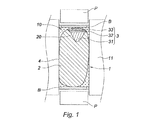
図1は、SPSエンクロージャ(図示せず)の中空円筒状黒鉛ダイ11のチャンバ10内に形成されたモールド1の部分縦断面図である。電圧端子Bおよび圧縮ピストンPは、フラッシュ焼結サイクルに従ってモールドを加圧してパルス電流を通電させることができるように調節される。
FIG. 1 is a partial longitudinal sectional view of a
このモールド1は、超合金製の元の部品と一致するくぼみの形状である。損傷部品2は、外表面、特に、部品の一部が欠損している、あるいは、浸食された、腐食した、もしくは酸化した面20を洗浄した後に、このモールド1に導入される。この面20上に、材料の連続層のアセンブリ3、すなわち、超合金粉末層31、白金シートとアルミニウムシートとから成る保護金属層32、およびイットリア安定化ジルコニア(式ZrO2Y2O3)のセラミック粉末から作られる熱バリア33が堆積される。
The
補修される部品の幾何学的形状に沿って、層はモールド1に組み込まれる前に損傷部品2に堆積される、あるいは、アセンブリ3がノズルによってこのモールドに注入されることができる。部品とアセンブリとは、局部圧力を印加することができるようにモールド内に配置された黒鉛ジャケット4内に配置される。部品1上に多層アセンブリ3を形成する上述の様々な方法は、当業者の能力の範囲内である。
Along the geometry of the part to be repaired, the layer can be deposited on the
フラッシュ焼結作業中は、温度および圧力を調節するサイクルは、電圧および圧力の所定の値に従ってプラグラムされたチャートに従って行われる。プログラムでは、8000Aに達する可能性のあるモールド内を流れる電流によって2000℃まで上昇する可能性のあるプラトー温度が規定される。 During the flash sintering operation, the cycle of adjusting temperature and pressure is performed according to a programmed chart according to predetermined values of voltage and pressure. The program defines a plateau temperature that can be raised to 2000 ° C. by the current flowing in the mold that can reach 8000A.
電流が流されることにより、例えば、約600℃/分以上で温度を急上昇させることができる。この速度により、焼結中に粒子が大きくなるのを防ぐことができるので、この速度は、ナノ材料の合成に望ましい。さらに、この速度により、図2に示されるように、均一に拡散が生じて、多層アセンブリ3の生成が維持されると同時に、層31−32−33の境界面における組成勾配G1およびG2の形成を促進し、さらに、焼結超合金層31と補修される部品2との間で材料が連続的に接着するのを促進する。
By passing an electric current, for example, the temperature can be rapidly increased at about 600 ° C./min or more. This speed is desirable for the synthesis of nanomaterials because it can prevent the particles from becoming large during sintering. In addition, this speed causes uniform diffusion and maintains the formation of the
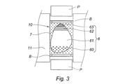
図3を参照すると、断面図は、SPSダイ11のチャンバ10内に形成されたモールド7内の層アセンブリ6の別の例を示している。この例では、モールド7は、部品の元の形状に復元するために損傷部品に追加される補修部と一致するくぼみの形状を有する。
Referring to FIG. 3, a cross-sectional view shows another example of a
上述の方法によれば、くぼみは、アセンブリ6もしくは多層構造を形成する層、つまり、補修される部品の面に合わせることができるろう付け用粉末層60、超合金粉末層61、Ni−Al−Zr組成物のシートから成る保護層62、イットリア安定化ジルコニア(式ZrO2Y2O3)のセラミック粉末で形成され、酸化ガドリニウムGd2O3がドープされた熱バリア63が連続して堆積することで埋められる。
According to the method described above, the indentations are formed in the
図4を参照すると、上述した条件で実行される焼結ステップにより、多層構造6内の層60−61−62−63のそれぞれの間に組成勾配G3、G4、G5が形成されたプリフォーム2aを得ることができる。焼結ろう付け層60は、補修される部品の損傷面に接合される外側面6bを有し、一部の超合金材料6sは、ろう付け面6b内のプリフォーム2aの表面に現れる。
Referring to FIG. 4, a
図5に示されている次のろう付けステップでは、プリフォーム2aのろう付け面6bは、補修される部品2の相補的形状ゾーン、つまり面20と接触した状態で配置される。次いで、プリフォーム2aおよびそれに沿って配置されている部品2は、適切な炉内で、少なくともろう付け用合金の溶融温度に等しい温度まで、例えば、銀系合金の場合では約700℃まで加熱される。その後、ろう付け面6bは、ろう付け用合金の溶融成分が面20を通って補修される部品2内に拡散することによって接着する。
In the next brazing step shown in FIG. 5, the
本発明は、上述および図示している例に限定されない。例えば、最初に、化学的および熱的に適合するセラミック材料の複数の層を、堆積させることも可能である。さらに、金属保護層と熱バリア層とは、部品が再構成された時点で、次の部品全体への堆積ステップで追加されてもよい。この場合、保護層と耐熱層は、有利には、事前に、損傷部品の表面から剥がされ、焼結はこれらの層が無い状態で行われる。その後、これらの層は、再構成された部品全体に焼結によって、堆積され接合される。 The invention is not limited to the examples described and illustrated. For example, first, multiple layers of chemically and thermally compatible ceramic material can be deposited. Furthermore, the metal protective layer and the thermal barrier layer may be added in a subsequent deposition step on the entire part when the part is reconfigured. In this case, the protective layer and the heat-resistant layer are advantageously peeled off beforehand from the surface of the damaged part and the sintering is carried out in the absence of these layers. These layers are then deposited and bonded by sintering over the reconstructed part.
Claims (7)
SPSフラッシュ焼結用エンクロージャダイ(11)内に損傷部品(2)の少なくとも補修部分に対応するくぼみの形状のモールド(1、7)を作製する準備ステップと、
その後、多層構造(6)を構成するろう付け用粉末(60)の層と超合金粉末の少なくとも1つの層(31、61)をモールド(1、7)内に導入するステップと、
その後、材料と部品(2)との接着部が拡散によって後で形成されるように、温度、圧力、継続時間が調節されたフラッシュ焼結サイクルに従って加圧しパルス電流を通電させることによって温度を急上昇させる焼結ステップとを含み、この焼結ステップにより、多層構造(6)内に組成勾配(G3、G4、G5)が形成されたプリフォーム(2a)であって、補修される部品(2)にさらに接合されるろう付け面(6b)と超合金材料(6s)とがプリフォーム(2a)の表面に現れたプリフォーム(2a)が作製され、さらに、
その後、プリフォーム(2a)のろう付け面(6b)が補修される部品に接着されるろう付けステップを含むことを特徴とする、補修のプロセス。 A process of local repair of a superalloy thermomechanical part (2),
A preparation step of preparing a mold (1,7) of the shape of the recess corresponds to at least the repaired portion of the S PS damaged parts in the flash sintering enclosure die (11) in (2),
Thereafter, a step of introducing at least one layer of the layer and the superalloy powder brazing powder (60) (31, 61) in the mold (1,7) constituting the multilayer structure (6),
Then, as the adhesive portion of the wood charge and the part (2) is formed subsequently by diffusion, temperature, pressure, temperature by energizing the pressurized pulse current in accordance with the adjusted duration flash sintering cycle and a sintering step of soar, this sintering step, a composition gradient in the multilayer structure (6) in (G3, G4, G5) preform formed (2a), the part to be repaired ( A preform (2a) is produced in which the brazing surface (6b) and the superalloy material (6s) to be further joined to 2) appear on the surface of the preform (2a) ,
Thereafter, a process of repair, characterized in that it comprises a brazing step in which the brazing surface (6b) of the preform (2a) is glued to the part to be repaired.
Applications Claiming Priority (3)
| Application Number | Priority Date | Filing Date | Title |
|---|---|---|---|
| FR1151832 | 2011-03-07 | ||
| FR1151832A FR2972379B1 (en) | 2011-03-07 | 2011-03-07 | METHOD FOR LOCALLY RECHARGING DAMAGED THERMOMECHANICAL PIECE AND PART THEREFORE PRODUCED, IN PARTICULAR TURBINE PIECE |
| PCT/FR2012/050459 WO2012120231A1 (en) | 2011-03-07 | 2012-03-06 | Process for local repair of a damaged thermomechanical part and part thus produced, in particular a turbine part |
Publications (3)
| Publication Number | Publication Date |
|---|---|
| JP2014513207A JP2014513207A (en) | 2014-05-29 |
| JP2014513207A5 JP2014513207A5 (en) | 2016-07-21 |
| JP6085256B2 true JP6085256B2 (en) | 2017-02-22 |
Family
ID=43902599
Family Applications (1)
| Application Number | Title | Priority Date | Filing Date |
|---|---|---|---|
| JP2013557155A Active JP6085256B2 (en) | 2011-03-07 | 2012-03-06 | Process of local repair of damaged thermomechanical parts and parts repaired according to the process, in particular turbine parts |
Country Status (9)
| Country | Link |
|---|---|
| US (1) | US9221101B2 (en) |
| EP (1) | EP2683509B1 (en) |
| JP (1) | JP6085256B2 (en) |
| CN (1) | CN103415365B (en) |
| BR (1) | BR112013022876A2 (en) |
| CA (1) | CA2828711C (en) |
| FR (1) | FR2972379B1 (en) |
| RU (1) | RU2598018C2 (en) |
| WO (1) | WO2012120231A1 (en) |
Families Citing this family (21)
| Publication number | Priority date | Publication date | Assignee | Title |
|---|---|---|---|---|
| US9102015B2 (en) * | 2013-03-14 | 2015-08-11 | Siemens Energy, Inc | Method and apparatus for fabrication and repair of thermal barriers |
| EP2840154A1 (en) * | 2013-08-21 | 2015-02-25 | MTU Aero Engines GmbH | Method for producing components from and with laves phases |
| US20160158840A1 (en) * | 2013-11-25 | 2016-06-09 | Marco Cologna | Use of spark plasma sintering for manufacturing superalloy compound components |
| WO2016060799A1 (en) * | 2014-10-14 | 2016-04-21 | Siemens Energy, Inc. | Laser additive manufacture of three-dimensional components containing multiple materials formed as integrated systems |
| US10350684B2 (en) * | 2015-11-10 | 2019-07-16 | General Electric Company | Additive manufacturing method for making complex film holes |
| FR3044946B1 (en) | 2015-12-14 | 2018-01-12 | Safran Aircraft Engines | ABRADABLE COATING WITH VARIABLE DENSITY |
| FR3044945B1 (en) * | 2015-12-14 | 2018-01-12 | Centre National De La Recherche Scientifique | ABRADABLE COATING WITH VARIABLE DENSITY |
| WO2017112610A1 (en) | 2015-12-21 | 2017-06-29 | General Electric Company | A repaired turbomachine component and corresponding repair method |
| FR3048630B1 (en) * | 2016-03-14 | 2020-02-21 | Centre National De La Recherche Scientifique | PROCESS FOR MANUFACTURING AN ABRADABLE PLATE AND FOR REPAIRING A TURBINE RING |
| US10702958B2 (en) * | 2017-02-22 | 2020-07-07 | General Electric Company | Method of manufacturing turbine airfoil and tip component thereof using ceramic core with witness feature |
| US11167348B2 (en) | 2017-06-28 | 2021-11-09 | Rolls-Royce Corporation | Joining metal or alloy components using electric current |
| FR3071178B1 (en) * | 2017-09-15 | 2022-02-25 | Safran | METHOD FOR MANUFACTURING A TURBOMACHINE PART BY ADDITIVE MANUFACTURING AND FLASH SINTERING |
| AT520756B1 (en) * | 2017-12-06 | 2019-07-15 | Montanuniv Leoben | METHOD FOR MANUFACTURING A MULTIMATERIAL COMPONENT CONNECTION AND THE MULTIMATERIAL COMPONENT CONNECTION |
| FR3086567B1 (en) * | 2018-10-02 | 2022-07-22 | Norimat | METHOD FOR MAKING A COUNTERFORM AND METHOD FOR MANUFACTURING PARTS OF COMPLEX SHAPE USING SUCH A COUNTER-FORM |
| CN110303259B (en) * | 2019-07-22 | 2021-06-08 | 中国航空制造技术研究院 | Method for manufacturing dissimilar alloy blisk structure |
| FR3105048B1 (en) * | 2019-12-20 | 2022-08-05 | Safran | MANUFACTURING SOLUTION FOR A MONOBLOC BLADE DISC |
| WO2021232146A1 (en) | 2020-05-21 | 2021-11-25 | Kilncore Inc. | High temperature, high pressure, powder-based, 3d printed object manufacturing |
| RU2761813C1 (en) * | 2021-03-11 | 2021-12-13 | Федеральное государственное бюджетное учреждение науки Институт гидродинамики им. М.А. Лаврентьева Сибирского отделения Российской академии наук (ИГиЛ СО РАН) | Additive method for obtaining dimension products from conductive ceramics by spark plasma sintering |
| US11541470B2 (en) | 2021-04-02 | 2023-01-03 | General Electric Company | Methods of furnace-less brazing |
| CN113462924B (en) * | 2021-06-18 | 2022-03-29 | 中国地质大学(武汉) | Titanium-plated diamond copper composite material and preparation method thereof |
| CN115849957B (en) * | 2022-11-25 | 2023-08-11 | 南京航空航天大学 | Rapid repairing method for damage defect of ceramic matrix composite |
Family Cites Families (19)
| Publication number | Priority date | Publication date | Assignee | Title |
|---|---|---|---|---|
| US3250892A (en) * | 1961-12-29 | 1966-05-10 | Inoue Kiyoshi | Apparatus for electrically sintering discrete bodies |
| US3241956A (en) * | 1963-05-30 | 1966-03-22 | Inoue Kiyoshi | Electric-discharge sintering |
| US4039330A (en) * | 1971-04-07 | 1977-08-02 | The International Nickel Company, Inc. | Nickel-chromium-cobalt alloys |
| SE463855B (en) * | 1989-06-01 | 1991-02-04 | Abb Stal Ab | SET FOR RECONSTRUCTION OF BLADES AND LEATHERS IN ANTURBINES DURING EROSION DAMAGE |
| RU1792805C (en) * | 1990-05-24 | 1993-02-07 | Республиканское Научно-Производственное Объединение "Агропромремонт" | Method of recovering engine cylinder sleeves |
| US5554837A (en) * | 1993-09-03 | 1996-09-10 | Chromalloy Gas Turbine Corporation | Interactive laser welding at elevated temperatures of superalloy articles |
| JPH1046208A (en) * | 1996-07-26 | 1998-02-17 | Tokin Corp | Production of ti-ni base alloy sintered body |
| JPH1143706A (en) * | 1997-07-23 | 1999-02-16 | Ishikawajima Harima Heavy Ind Co Ltd | Method for repairing metallic part |
| US6384365B1 (en) * | 2000-04-14 | 2002-05-07 | Siemens Westinghouse Power Corporation | Repair and fabrication of combustion turbine components by spark plasma sintering |
| JP2001335813A (en) * | 2000-05-25 | 2001-12-04 | Japan Atom Energy Res Inst | Method for producing structural material having silicon gradient composite structure by discharge plasma sintering method |
| CN1292864C (en) * | 2001-01-20 | 2007-01-03 | 昆明理工大学 | Method for copper powder plasma activated sintering |
| JP2003342617A (en) * | 2002-05-30 | 2003-12-03 | Mitsubishi Heavy Ind Ltd | REPAIRED HIGH-TEMPERATURE COMPONENT MADE OF HEAT- RESISTANT ALLOY, REPAIRED GAS-TURBINE BLADE MADE OF Ni- BASED HEAT RESISTANT ALLOY, METHOD FOR REPAIRING GAS- TURBINE BLADE OF Ni-BASED HEAT RESISTANT ALLOY, AND METHOD FOR REPAIRING GAS-TURBINE BLADE MADE OF HEAT RESISTANT ALLOY |
| US7343676B2 (en) * | 2004-01-29 | 2008-03-18 | United Technologies Corporation | Method of restoring dimensions of an airfoil and preform for performing same |
| RU2344913C2 (en) * | 2006-01-10 | 2009-01-27 | Владимир Владимирович Гончаренко | Earth board reworking method |
| US20100237134A1 (en) * | 2006-07-17 | 2010-09-23 | David Vincent Bucci | Repair process for coated articles |
| RU2354523C1 (en) * | 2007-09-12 | 2009-05-10 | Федеральное государственное унитарное предприятие "Московское машиностроительное производственное предприятие "САЛЮТ" (ФГУП "ММПП "САЛЮТ") | Method of repairing gas turbine engine blade labyrinth seal knife edges |
| FR2932496B1 (en) * | 2008-06-13 | 2011-05-20 | Snecma | METHOD FOR DEPOSITING A THERMAL BARRIER |
| FR2941965B1 (en) * | 2009-02-10 | 2011-05-13 | Snecma | METHOD FOR DEPOSITING A PROTECTIVE LAYER ON A WORKPIECE |
| EP2435595B1 (en) * | 2009-05-26 | 2020-07-29 | Siemens Aktiengesellschaft | Layered coating system with a mcralx layer and a chromium rich layer and a method to produce it |
-
2011
- 2011-03-07 FR FR1151832A patent/FR2972379B1/en active Active
-
2012
- 2012-03-06 CN CN201280011974.9A patent/CN103415365B/en active Active
- 2012-03-06 RU RU2013140968/02A patent/RU2598018C2/en active
- 2012-03-06 BR BR112013022876A patent/BR112013022876A2/en not_active Application Discontinuation
- 2012-03-06 JP JP2013557155A patent/JP6085256B2/en active Active
- 2012-03-06 EP EP12720222.4A patent/EP2683509B1/en active Active
- 2012-03-06 WO PCT/FR2012/050459 patent/WO2012120231A1/en active Application Filing
- 2012-03-06 CA CA2828711A patent/CA2828711C/en active Active
- 2012-03-06 US US14/003,453 patent/US9221101B2/en active Active
Also Published As
| Publication number | Publication date |
|---|---|
| RU2013140968A (en) | 2015-04-20 |
| JP2014513207A (en) | 2014-05-29 |
| RU2598018C2 (en) | 2016-09-20 |
| EP2683509A1 (en) | 2014-01-15 |
| CA2828711A1 (en) | 2012-09-13 |
| CA2828711C (en) | 2019-04-02 |
| BR112013022876A2 (en) | 2016-12-06 |
| WO2012120231A1 (en) | 2012-09-13 |
| FR2972379B1 (en) | 2014-01-17 |
| CN103415365B (en) | 2017-01-18 |
| CN103415365A (en) | 2013-11-27 |
| EP2683509B1 (en) | 2019-02-27 |
| US20130344347A1 (en) | 2013-12-26 |
| US9221101B2 (en) | 2015-12-29 |
| FR2972379A1 (en) | 2012-09-14 |
Similar Documents
| Publication | Publication Date | Title |
|---|---|---|
| JP6085256B2 (en) | Process of local repair of damaged thermomechanical parts and parts repaired according to the process, in particular turbine parts | |
| JP2014513207A5 (en) | ||
| US8956478B2 (en) | Process for joining refractory ceramic parts by spark plasma sintering (SPS) | |
| US6384365B1 (en) | Repair and fabrication of combustion turbine components by spark plasma sintering | |
| JP6188678B2 (en) | Method for producing parts having complex shapes by flash sintering and apparatus for carrying out such a method | |
| EP2692464B1 (en) | Methods for manufacturing titanium aluminide components from articles formed by consolidation processes | |
| CN101941106B (en) | High temperature brazing process of super nickel laminated material and Cr18-Ni8 stainless steel | |
| JP7358034B2 (en) | How to make pre-sintered preforms | |
| US6223976B1 (en) | Process for the assembly or refacing of titanium aluminide articles by diffusion brazing | |
| JP2010100940A (en) | Method for repairing machine component, method for manufacturing restored machine component, method for manufacturing machine component and gas-turbine engine | |
| RU2550670C2 (en) | Production of metal article by laser cyclic application of powder and unit to this end | |
| JP6356823B2 (en) | Heat-resistant member with thermal barrier coating and method for manufacturing the same | |
| US7112301B2 (en) | HIP manufacture of a hollow component | |
| JP2007301590A (en) | Method for manufacturing joined body | |
| JP2015086447A (en) | Target material for cylindrical sputtering target, cylindrical sputtering target, and method of manufacturing the same | |
| RU2761813C1 (en) | Additive method for obtaining dimension products from conductive ceramics by spark plasma sintering | |
| JP2002035955A (en) | Manufacturing method for aluminum alloy composite member by electrified joint | |
| JP2017207057A (en) | Article, component, and method of making component | |
| JPH10110203A (en) | Overlaying sheet for metallic material, and method of overlaying for metallic material | |
| CN116197503A (en) | Welded part of hard alloy and steel and preparation method thereof | |
| JP2008297567A (en) | Method for manufacturing long fiber reinforced metal-matrix composite material and compound cross-section member containing it | |
| JP2005219100A (en) | Joined material, and method for manufacturing the same | |
| JPH0225703B2 (en) |
Legal Events
| Date | Code | Title | Description |
|---|---|---|---|
| A621 | Written request for application examination |
Free format text: JAPANESE INTERMEDIATE CODE: A621 Effective date: 20150213 |
|
| A977 | Report on retrieval |
Free format text: JAPANESE INTERMEDIATE CODE: A971007 Effective date: 20151209 |
|
| A131 | Notification of reasons for refusal |
Free format text: JAPANESE INTERMEDIATE CODE: A131 Effective date: 20151215 |
|
| A601 | Written request for extension of time |
Free format text: JAPANESE INTERMEDIATE CODE: A601 Effective date: 20160314 |
|
| A521 | Request for written amendment filed |
Free format text: JAPANESE INTERMEDIATE CODE: A523 Effective date: 20160602 |
|
| A524 | Written submission of copy of amendment under article 19 pct |
Free format text: JAPANESE INTERMEDIATE CODE: A524 Effective date: 20160602 |
|
| A02 | Decision of refusal |
Free format text: JAPANESE INTERMEDIATE CODE: A02 Effective date: 20160816 |
|
| A521 | Request for written amendment filed |
Free format text: JAPANESE INTERMEDIATE CODE: A523 Effective date: 20161205 |
|
| A911 | Transfer to examiner for re-examination before appeal (zenchi) |
Free format text: JAPANESE INTERMEDIATE CODE: A911 Effective date: 20161212 |
|
| TRDD | Decision of grant or rejection written | ||
| A01 | Written decision to grant a patent or to grant a registration (utility model) |
Free format text: JAPANESE INTERMEDIATE CODE: A01 Effective date: 20170110 |
|
| A61 | First payment of annual fees (during grant procedure) |
Free format text: JAPANESE INTERMEDIATE CODE: A61 Effective date: 20170127 |
|
| R150 | Certificate of patent or registration of utility model |
Ref document number: 6085256 Country of ref document: JP Free format text: JAPANESE INTERMEDIATE CODE: R150 |
|
| R250 | Receipt of annual fees |
Free format text: JAPANESE INTERMEDIATE CODE: R250 |
|
| R250 | Receipt of annual fees |
Free format text: JAPANESE INTERMEDIATE CODE: R250 |
|
| R250 | Receipt of annual fees |
Free format text: JAPANESE INTERMEDIATE CODE: R250 |
|
| R250 | Receipt of annual fees |
Free format text: JAPANESE INTERMEDIATE CODE: R250 |
|
| R250 | Receipt of annual fees |
Free format text: JAPANESE INTERMEDIATE CODE: R250 |