EP2435595B1 - Layered coating system with a mcralx layer and a chromium rich layer and a method to produce it - Google Patents
Layered coating system with a mcralx layer and a chromium rich layer and a method to produce it Download PDFInfo
- Publication number
- EP2435595B1 EP2435595B1 EP09788779.8A EP09788779A EP2435595B1 EP 2435595 B1 EP2435595 B1 EP 2435595B1 EP 09788779 A EP09788779 A EP 09788779A EP 2435595 B1 EP2435595 B1 EP 2435595B1
- Authority
- EP
- European Patent Office
- Prior art keywords
- layer
- mcrx
- rich
- chromium
- continuous
- Prior art date
- Legal status (The legal status is an assumption and is not a legal conclusion. Google has not performed a legal analysis and makes no representation as to the accuracy of the status listed.)
- Active
Links
Images


Classifications
-
- C—CHEMISTRY; METALLURGY
- C23—COATING METALLIC MATERIAL; COATING MATERIAL WITH METALLIC MATERIAL; CHEMICAL SURFACE TREATMENT; DIFFUSION TREATMENT OF METALLIC MATERIAL; COATING BY VACUUM EVAPORATION, BY SPUTTERING, BY ION IMPLANTATION OR BY CHEMICAL VAPOUR DEPOSITION, IN GENERAL; INHIBITING CORROSION OF METALLIC MATERIAL OR INCRUSTATION IN GENERAL
- C23C—COATING METALLIC MATERIAL; COATING MATERIAL WITH METALLIC MATERIAL; SURFACE TREATMENT OF METALLIC MATERIAL BY DIFFUSION INTO THE SURFACE, BY CHEMICAL CONVERSION OR SUBSTITUTION; COATING BY VACUUM EVAPORATION, BY SPUTTERING, BY ION IMPLANTATION OR BY CHEMICAL VAPOUR DEPOSITION, IN GENERAL
- C23C4/00—Coating by spraying the coating material in the molten state, e.g. by flame, plasma or electric discharge
- C23C4/18—After-treatment
-
- C—CHEMISTRY; METALLURGY
- C23—COATING METALLIC MATERIAL; COATING MATERIAL WITH METALLIC MATERIAL; CHEMICAL SURFACE TREATMENT; DIFFUSION TREATMENT OF METALLIC MATERIAL; COATING BY VACUUM EVAPORATION, BY SPUTTERING, BY ION IMPLANTATION OR BY CHEMICAL VAPOUR DEPOSITION, IN GENERAL; INHIBITING CORROSION OF METALLIC MATERIAL OR INCRUSTATION IN GENERAL
- C23C—COATING METALLIC MATERIAL; COATING MATERIAL WITH METALLIC MATERIAL; SURFACE TREATMENT OF METALLIC MATERIAL BY DIFFUSION INTO THE SURFACE, BY CHEMICAL CONVERSION OR SUBSTITUTION; COATING BY VACUUM EVAPORATION, BY SPUTTERING, BY ION IMPLANTATION OR BY CHEMICAL VAPOUR DEPOSITION, IN GENERAL
- C23C10/00—Solid state diffusion of only metal elements or silicon into metallic material surfaces
- C23C10/02—Pretreatment of the material to be coated
-
- C—CHEMISTRY; METALLURGY
- C23—COATING METALLIC MATERIAL; COATING MATERIAL WITH METALLIC MATERIAL; CHEMICAL SURFACE TREATMENT; DIFFUSION TREATMENT OF METALLIC MATERIAL; COATING BY VACUUM EVAPORATION, BY SPUTTERING, BY ION IMPLANTATION OR BY CHEMICAL VAPOUR DEPOSITION, IN GENERAL; INHIBITING CORROSION OF METALLIC MATERIAL OR INCRUSTATION IN GENERAL
- C23C—COATING METALLIC MATERIAL; COATING MATERIAL WITH METALLIC MATERIAL; SURFACE TREATMENT OF METALLIC MATERIAL BY DIFFUSION INTO THE SURFACE, BY CHEMICAL CONVERSION OR SUBSTITUTION; COATING BY VACUUM EVAPORATION, BY SPUTTERING, BY ION IMPLANTATION OR BY CHEMICAL VAPOUR DEPOSITION, IN GENERAL
- C23C28/00—Coating for obtaining at least two superposed coatings either by methods not provided for in a single one of groups C23C2/00 - C23C26/00 or by combinations of methods provided for in subclasses C23C and C25C or C25D
- C23C28/02—Coating for obtaining at least two superposed coatings either by methods not provided for in a single one of groups C23C2/00 - C23C26/00 or by combinations of methods provided for in subclasses C23C and C25C or C25D only coatings only including layers of metallic material
- C23C28/021—Coating for obtaining at least two superposed coatings either by methods not provided for in a single one of groups C23C2/00 - C23C26/00 or by combinations of methods provided for in subclasses C23C and C25C or C25D only coatings only including layers of metallic material including at least one metal alloy layer
- C23C28/022—Coating for obtaining at least two superposed coatings either by methods not provided for in a single one of groups C23C2/00 - C23C26/00 or by combinations of methods provided for in subclasses C23C and C25C or C25D only coatings only including layers of metallic material including at least one metal alloy layer with at least one MCrAlX layer
-
- C—CHEMISTRY; METALLURGY
- C23—COATING METALLIC MATERIAL; COATING MATERIAL WITH METALLIC MATERIAL; CHEMICAL SURFACE TREATMENT; DIFFUSION TREATMENT OF METALLIC MATERIAL; COATING BY VACUUM EVAPORATION, BY SPUTTERING, BY ION IMPLANTATION OR BY CHEMICAL VAPOUR DEPOSITION, IN GENERAL; INHIBITING CORROSION OF METALLIC MATERIAL OR INCRUSTATION IN GENERAL
- C23C—COATING METALLIC MATERIAL; COATING MATERIAL WITH METALLIC MATERIAL; SURFACE TREATMENT OF METALLIC MATERIAL BY DIFFUSION INTO THE SURFACE, BY CHEMICAL CONVERSION OR SUBSTITUTION; COATING BY VACUUM EVAPORATION, BY SPUTTERING, BY ION IMPLANTATION OR BY CHEMICAL VAPOUR DEPOSITION, IN GENERAL
- C23C28/00—Coating for obtaining at least two superposed coatings either by methods not provided for in a single one of groups C23C2/00 - C23C26/00 or by combinations of methods provided for in subclasses C23C and C25C or C25D
- C23C28/02—Coating for obtaining at least two superposed coatings either by methods not provided for in a single one of groups C23C2/00 - C23C26/00 or by combinations of methods provided for in subclasses C23C and C25C or C25D only coatings only including layers of metallic material
- C23C28/023—Coating for obtaining at least two superposed coatings either by methods not provided for in a single one of groups C23C2/00 - C23C26/00 or by combinations of methods provided for in subclasses C23C and C25C or C25D only coatings only including layers of metallic material only coatings of metal elements only
-
- C—CHEMISTRY; METALLURGY
- C23—COATING METALLIC MATERIAL; COATING MATERIAL WITH METALLIC MATERIAL; CHEMICAL SURFACE TREATMENT; DIFFUSION TREATMENT OF METALLIC MATERIAL; COATING BY VACUUM EVAPORATION, BY SPUTTERING, BY ION IMPLANTATION OR BY CHEMICAL VAPOUR DEPOSITION, IN GENERAL; INHIBITING CORROSION OF METALLIC MATERIAL OR INCRUSTATION IN GENERAL
- C23C—COATING METALLIC MATERIAL; COATING MATERIAL WITH METALLIC MATERIAL; SURFACE TREATMENT OF METALLIC MATERIAL BY DIFFUSION INTO THE SURFACE, BY CHEMICAL CONVERSION OR SUBSTITUTION; COATING BY VACUUM EVAPORATION, BY SPUTTERING, BY ION IMPLANTATION OR BY CHEMICAL VAPOUR DEPOSITION, IN GENERAL
- C23C28/00—Coating for obtaining at least two superposed coatings either by methods not provided for in a single one of groups C23C2/00 - C23C26/00 or by combinations of methods provided for in subclasses C23C and C25C or C25D
- C23C28/30—Coatings combining at least one metallic layer and at least one inorganic non-metallic layer
- C23C28/32—Coatings combining at least one metallic layer and at least one inorganic non-metallic layer including at least one pure metallic layer
- C23C28/321—Coatings combining at least one metallic layer and at least one inorganic non-metallic layer including at least one pure metallic layer with at least one metal alloy layer
- C23C28/3215—Coatings combining at least one metallic layer and at least one inorganic non-metallic layer including at least one pure metallic layer with at least one metal alloy layer at least one MCrAlX layer
-
- C—CHEMISTRY; METALLURGY
- C23—COATING METALLIC MATERIAL; COATING MATERIAL WITH METALLIC MATERIAL; CHEMICAL SURFACE TREATMENT; DIFFUSION TREATMENT OF METALLIC MATERIAL; COATING BY VACUUM EVAPORATION, BY SPUTTERING, BY ION IMPLANTATION OR BY CHEMICAL VAPOUR DEPOSITION, IN GENERAL; INHIBITING CORROSION OF METALLIC MATERIAL OR INCRUSTATION IN GENERAL
- C23C—COATING METALLIC MATERIAL; COATING MATERIAL WITH METALLIC MATERIAL; SURFACE TREATMENT OF METALLIC MATERIAL BY DIFFUSION INTO THE SURFACE, BY CHEMICAL CONVERSION OR SUBSTITUTION; COATING BY VACUUM EVAPORATION, BY SPUTTERING, BY ION IMPLANTATION OR BY CHEMICAL VAPOUR DEPOSITION, IN GENERAL
- C23C28/00—Coating for obtaining at least two superposed coatings either by methods not provided for in a single one of groups C23C2/00 - C23C26/00 or by combinations of methods provided for in subclasses C23C and C25C or C25D
- C23C28/30—Coatings combining at least one metallic layer and at least one inorganic non-metallic layer
- C23C28/32—Coatings combining at least one metallic layer and at least one inorganic non-metallic layer including at least one pure metallic layer
- C23C28/322—Coatings combining at least one metallic layer and at least one inorganic non-metallic layer including at least one pure metallic layer only coatings of metal elements only
-
- C—CHEMISTRY; METALLURGY
- C23—COATING METALLIC MATERIAL; COATING MATERIAL WITH METALLIC MATERIAL; CHEMICAL SURFACE TREATMENT; DIFFUSION TREATMENT OF METALLIC MATERIAL; COATING BY VACUUM EVAPORATION, BY SPUTTERING, BY ION IMPLANTATION OR BY CHEMICAL VAPOUR DEPOSITION, IN GENERAL; INHIBITING CORROSION OF METALLIC MATERIAL OR INCRUSTATION IN GENERAL
- C23C—COATING METALLIC MATERIAL; COATING MATERIAL WITH METALLIC MATERIAL; SURFACE TREATMENT OF METALLIC MATERIAL BY DIFFUSION INTO THE SURFACE, BY CHEMICAL CONVERSION OR SUBSTITUTION; COATING BY VACUUM EVAPORATION, BY SPUTTERING, BY ION IMPLANTATION OR BY CHEMICAL VAPOUR DEPOSITION, IN GENERAL
- C23C28/00—Coating for obtaining at least two superposed coatings either by methods not provided for in a single one of groups C23C2/00 - C23C26/00 or by combinations of methods provided for in subclasses C23C and C25C or C25D
- C23C28/30—Coatings combining at least one metallic layer and at least one inorganic non-metallic layer
- C23C28/34—Coatings combining at least one metallic layer and at least one inorganic non-metallic layer including at least one inorganic non-metallic material layer, e.g. metal carbide, nitride, boride, silicide layer and their mixtures, enamels, phosphates and sulphates
- C23C28/345—Coatings combining at least one metallic layer and at least one inorganic non-metallic layer including at least one inorganic non-metallic material layer, e.g. metal carbide, nitride, boride, silicide layer and their mixtures, enamels, phosphates and sulphates with at least one oxide layer
- C23C28/3455—Coatings combining at least one metallic layer and at least one inorganic non-metallic layer including at least one inorganic non-metallic material layer, e.g. metal carbide, nitride, boride, silicide layer and their mixtures, enamels, phosphates and sulphates with at least one oxide layer with a refractory ceramic layer, e.g. refractory metal oxide, ZrO2, rare earth oxides or a thermal barrier system comprising at least one refractory oxide layer
-
- Y—GENERAL TAGGING OF NEW TECHNOLOGICAL DEVELOPMENTS; GENERAL TAGGING OF CROSS-SECTIONAL TECHNOLOGIES SPANNING OVER SEVERAL SECTIONS OF THE IPC; TECHNICAL SUBJECTS COVERED BY FORMER USPC CROSS-REFERENCE ART COLLECTIONS [XRACs] AND DIGESTS
- Y02—TECHNOLOGIES OR APPLICATIONS FOR MITIGATION OR ADAPTATION AGAINST CLIMATE CHANGE
- Y02T—CLIMATE CHANGE MITIGATION TECHNOLOGIES RELATED TO TRANSPORTATION
- Y02T50/00—Aeronautics or air transport
- Y02T50/60—Efficient propulsion technologies, e.g. for aircraft
-
- Y—GENERAL TAGGING OF NEW TECHNOLOGICAL DEVELOPMENTS; GENERAL TAGGING OF CROSS-SECTIONAL TECHNOLOGIES SPANNING OVER SEVERAL SECTIONS OF THE IPC; TECHNICAL SUBJECTS COVERED BY FORMER USPC CROSS-REFERENCE ART COLLECTIONS [XRACs] AND DIGESTS
- Y10—TECHNICAL SUBJECTS COVERED BY FORMER USPC
- Y10T—TECHNICAL SUBJECTS COVERED BY FORMER US CLASSIFICATION
- Y10T428/00—Stock material or miscellaneous articles
- Y10T428/12—All metal or with adjacent metals
- Y10T428/12493—Composite; i.e., plural, adjacent, spatially distinct metal components [e.g., layers, joint, etc.]
- Y10T428/12771—Transition metal-base component
- Y10T428/12861—Group VIII or IB metal-base component
- Y10T428/12944—Ni-base component
Definitions
- the invention relates to a layered system with a MCrAlX layer, a Cr-rich layer that is uniquely resistant to both oxidation and hot corrosion and a method to produce such a system.
- a MCrAlX layer Preferably an aluminide layer is applied.
- EP0587341 describes a high temperature corrosion resistant composite coating where the process includes the following steps:
- EP 1327702 describes a MCrAlY coating system comprising an inner layer of beta-NiAl and an outer layer of gamma/beta-MCrAlY and TBC.
- the oxidation resistance can be improved for these layers of coating by adding 0.1-4% Si.
- the coatings are deposited using a gas phase method, CVD, PVD etc..
- US 2005/0003227 describes a similar system as in US 227, but here is also an intermediate layer of a platinum type of metal included. In the document it is stated that the oxidation resistance can be improved for these layers of coating by adding 0.1-4% Si.
- EP 1029100/ US 6416882 describes a MCrAlY type of bond coat comprising up to 2% silicon.
- Aluminide and/or chromium modified coating systems are also described in US 7,229,701 , US 6,183,888 , US 7,060,366 , US 6,287,644 , EP 1 082 216 , US 6,001,492 , US 5,507,623 , EP 1 541 808 and US 6,569,492 .
- EP 0587341 describes a high temperature corrosion resistant composite coating where the process includes the following steps:
- the problem is solved by a layer system according to claim 1 and a method to produce it according to claim 16.
- the concept behind the invention is based on different coating chemistries being suited to protect a substrate within certain temperature and environmental criteria.
- an outer ⁇ -NiAl-layer provides the protection by forming a tenacious thin Alumina oxide in reaction with the high temperature and oxygen in the system, this reaction is typical of the similar ⁇ -NiAl coatings found in industry and well documented in literature.
- temperatures of around 750°C to 800°C up to around 950°C a broad front attack can occur depleting unprotected substrate materials of Cr and Al. Again the use of an Alumina forming ⁇ -NiAl coating will protect against type I corrosion.
- a strain complaint base layer is added in the form of an MCrAlY coating, which provides a degree of strain compliance as well as a final layer of protection should the ⁇ -NiAl and ⁇ -Cr be compromised.
- the layered coating structure essentially allows the environment to "select" the coating composition most suitable to provide protection. The concept can be clearly demonstrated in figure 3 .
- the introduction of Si or other beneficial elements can increase the expected life of the ⁇ -Cr layer.
- Figure 1 shows one exemplary component 1 as a layer system of the invention.
- the component 1 has a metallic substrate 4 which preferably comprises a heat resistant cast or wrought nickel or cobalt alloy, which is preferably Hastelloy X.
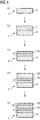
- MCrX layer 7 On the substrate 4 in (a.) in Fig. 4 ) an inner or lowest MCrX layer 7 is applied, especially only one MCrX layer 7 is applied in (b.) in Fig. 4 ) where X is yttrium (Y) and/or silicon (Si) and/or boron (B) and/or aluminum (Al).
- the inner MCrX layer 7 comprises MCrAlX' with X' at least Yttrium (Y) and is preferably only Yttrium (Y).
- This inner MCrAlX' layer 7 comprises especially a NiCrAlY layer and very especially comprises in at% Ni, 22% Cr, 10% Al, 1,0% Y, especially consists of Amdry 962.
- the inner MCrX layer 7 is preferably applied by HVOF.
- the inner MCrX layer 7 is direct on the substrate 4.
- a chromium rich layer 10 is applied on (c.) in Fig. 4 )), that is an ⁇ -Cr-layer.
- the chromizing is preferably performed from 1000°C to 1150°C preferably from 1 to 6 hours, very preferably at 1050°C -1075°C for 2h to 4h.
- the chromizing treatment will lead at least partly to a diffusion layer on the inner layer 7 (Therefore the reference 7 in Fig 4 c) represents the thickness of the inner layer 7 or that a diffusion layer is present and not one composition).
- the chromium rich layer 10 is preferably a diffusion layer.
- This layer system 1 is preferably heat treated, so that the overlay Cr layer is diffused into the inner MCrAlX' layer 7.
- a first outer MCrX'' layer 13 is applied on which is preferably the outer most layer (d.) in Fig. 4 ).
- This MCrX'' layer X'' is preferably yttrium (Y), silicon (Si) and boron (B).
- the first outer MCrX'' layer 13 can be a silicon and/or boron-containing nickel chromium alloy Ni-Cr-Si-B.
- This first outer MCrX'' layer 13 has a different composition than the inner layer 7 and is very especially a NiCrSiB layer (Amdry 103 which consists of in at% 74% Ni, 17% Cr, 9.2% Y, 9%Si, 0.1% B).
- a stabilizing heat treatment is preferably performed. This stabilizing heat treatment is performed at temperatures preferably 1000°C to 1200°C preferably for 1 to 6 hours, preferably at 1000 to 1025°C for 6h.
- a second outer layer 19 is present on or in the first outer layer 13.
- the second outer layer 19 is an aluminum rich layer as shown in figure 3 .
- the outer layer 19 is a diffusion layer.
- the first outer MCrX'' layer 13 can be aluminized to achieve the second outer layer 19 (e.) in Fig. 4 ).
- the aluminizing treatment is performed at temperatures preferably from 1050°C to 1115°C preferably for 1 to 10 hours, preferably at 1070°C to 1095°C for 7h.
- a final anneal treatment preferably at 1000°C to 1150°C for 1 to 6 hours, preferably at 1080°C for 2h, very preferably in vacuum.
- the component 1 has a metallic substrate 4 which preferably comprises a heat resistant cast or wrought nickel or cobalt alloy.
- this substrate is preferably "Hastelloy XTM" a commercially available wrought nickel alloy that nominally contains 47% Ni, 22 Cr, 18.5 Fe, 9 Mo, 1.5 Co, 1 Si, 1 Mn, 0.1 C.
- a first inner MCrAlX' layer 7' is applied, where X' is at least yttrium (Y) and is preferably only Yttrium (Y).
- This first inner MCrAlX' layer 7' comprises especially a NiCrAlY layer and very especially comprises in at% 67% Ni, 22% Cr, 10% Al, 1,0% Y, especially consists of Amdry 962.
- the first inner MCrAlX' layer 7' is preferably applied by HVOF.
- a second inner layer 16 is applied on the first inner MCrAlX' layer 7' (c.) in Fig. 5 ).
- This additional layer 16 has a different composition than the first inner layer 7' and is very especially a NiCrSiB layer (Amdry 103 which consists of in at% 74 Ni, I7 Cr, 9.2 Si, 0.1 B).
- the second inner layer 16 is preferably applied by HVOF.
- a chromium rich layer 10 is applied on, especially an ⁇ -Cr-layer (d.) in Fig. 5 , therefore the reference 16 in Fig 5 d) represents the thickness of the inner layer 16 or that a diffusion layer is present and not one composition).
- the chromizing is preferably performed from 1000°C to 1150°C preferably for 1 to 6 hours, preferably at 1050°C - 1075°C for 2h to 4h.
- the chromizing treatment will preferably lead to diffusion layer on the first inner layer 7'.
- This layer system 1 is preferably heat treated, so that the overlay ⁇ -Cr is diffused into the inner MCrAlX' layer 7' .
- an aluminide layer 22 is applied (e.) in Fig. 5 ). This is preferably achieved by Ni-plating the chromium rich layer 10 and aluminizing this plated Ni-Layer.
- the Ni-plate has preferably has a thickness of 10 ⁇ m to 20 ⁇ m.
- an annealing heat treatment after Ni-plating is performed, preferably at 1121°C for preferably 2h. This annealing treatment is preferably performed in vacuum.
- the following aluminizing is performed preferably at 1080°C for preferably 7h.
- a final annealing heat treatment is performed, preferably at 1080°C for 2h. This annealing treatment is preferably performed in vacuum.
- the chromizing or aluminizing can lead to diffusion layers as shown in Figures 4 , 5 or as overlays as shown in Figures 1, 2 or 3 . But this is not limiting. Both features can be present.
- Base coat MCrAlY sprayed by HVOF or Plasma (could be sprayed by suitable alternative such as VPS or LPPS).
- Cr Rich Layer Applied by CVD or above-the-source Chromizing methods. It was found that a 4 h Chromizing cycle was required to ensure a stable Cr layer during subsequent annealing processes.
- Ni Ni plating 10 ⁇ m to 20 ⁇ m
- Aluminizing Applied by CVD or above the source Aluminizing methods. Final annealing would be required to reintroduce the mechanical properties of the substrate materials.
- Figure 6 shows, by way of example, a gas turbine 100 in the form of a longitudinal part section.
- the gas turbine 100 has a rotor 103, which is mounted such that it can rotate about an axis of rotation 102 and has a shaft 101, also known as the turbine rotor.
- the annular combustion chamber 110 is in communication with a, for example annular, hot-gas duct 111 where, for example, four successive turbine stages 112 form the turbine 108.
- Each turbine stage 112 is formed, for example, from two blade or vane rings. As seen in the direction of flow of a working medium 113, a row 125 formed from rotor blades 120 follows a row 115 of guide vanes in the hot-gas duct 111.
- the guide vanes 130 are secured to an inner housing 138 of a stator 143, whereas the rotor blades 120 of a row 125 are fitted to the rotor 103, for example by means of a turbine disk 133.
- a generator or machine (not shown) is coupled to the rotor 103.
- the compressor 105 When the gas turbine 100 is operating, the compressor 105 sucks in air 135 through the intake housing 104 and compresses it. The compressed air which is provided at the turbine-side end of the compressor 105 is passed to the burners 107, where it is mixed with a fuel. The mixture is then burnt in the combustion chamber 110 to form the working medium 133. From there, the working medium 133 flows along the hot-gas duct 111 past the guide vanes 130 and the rotor blades 120. The working medium 113 expands at the rotor blades 120, transferring its momentum, so that the rotor blades 120 drive the rotor 103 and the rotor drives the machine coupled to it.
- the components which are exposed to the hot working medium 113 are subject to thermal loads.
- the guide vanes 130 and rotor blades 120 of the first turbine stage 112, as seen in the direction of flow of the working medium 113, together with the heat shield elements which line the annular combustion chamber 110, are subject to the highest thermal loads. To withstand the temperatures prevailing there, these components can be cooled by means of a coolant.
- substrates of the components it is likewise possible for substrates of the components to have a directional structure, i.e. they are in single-crystal form (SX structure) or include only longitudinally directed grains (DS structure).
- SX structure single-crystal form
- DS structure longitudinally directed grains
- iron-base, nickel-base or cobalt-base superalloys are used as material for the components, in particular for the turbine blades and vanes 120, 130 and components of the combustion chamber 110.
- Superalloys of this type are known, for example, from EP 1 204 776 B1 , EP 1 306 454 , EP 1 319 729 A1 , WO 99/67435 or WO 00/44949 ; these documents form part of the present disclosure with regard to the chemical composition of the alloys.
- the blades and vanes 120, 130 may likewise have coatings to protect against corrosion (MCrAlX; M is at least one element selected from the group consisting of iron (Fe), cobalt (Co), nickel (Ni), X is an active element and stands for yttrium (Y) and/or silicon and/or at least one of the rare earth elements or hafnium). Alloys of this type are known from EP 0 486 489 B1 , EP 0 786 017 B1 , EP 0 412 397 B1 or EP 1 306 454 A1 , which are intended to form part of the present disclosure with regard to the chemical composition.
- a thermal barrier coating consisting, for example, of ZrO 2 , Y 2 O 4 -ZrO 2 , i.e. it is not, is partially or is completely stabilized by yttrium oxide and/or calcium oxide and/or magnesium oxide, may also be present on the MCrAlX.
- Columnar grains are produced in the thermal barrier coating by suitable coating processes, such as for example electron beam physical vapor deposition (EB-PVD).
- the guide vane 130 has a guide vane root (not shown here) facing the inner housing 138 of the turbine 108 and a guide vane head on the opposite side from the guide vane root.
- the guide vane head faces the rotor 103 and is fixed to a securing ring 140 of the stator 143.
- Figure 7 shows a perspective view of a rotor blade 120 or guide vane 130 of a turbo machine, which extends along a longitudinal axis 121.
- the turbo machine may be a gas turbine of an aircraft or of a power plant for generating electricity, a steam turbine or a compressor.
- the blade or vane 120, 130 has a securing region 400, an adjoining blade or vane platform 403 and a main blade or main part 406 in succession along the longitudinal axis 121.
- the vane 130 may have a further platform (not shown) at its vane tip 415.
- a blade or vane root 183 which is used to secure the rotor blades 120, 130 to a shaft or disk (not shown), is formed in the securing region 400.
- the blade or vane root 183 is designed, for example, in hammerhead form. Other configurations, such as fir-tree or dovetail root, are also possible.
- the blade or vane 120, 130 has a leading edge 409 and a trailing edge 412 for a medium which flows past the main blade or vane part 406.
- blades or vanes 120, 130 by way of example, solid metallic materials, in particular superalloys, are used in all regions 400, 403, 406 of the blade or vane 120, 130.
- superalloys of this type are known, for example, from EP 1 204 776 B1 , EP 1 306 454 , EP 1 319 729 A1 , WO 99/67435 or WO 00/44949 ; these documents form part of the present disclosure with regard to the chemical composition of the alloy.
- the blade or vane 120, 130 may in this case be produced by a casting process, also by means of directional solidification, by a forging process, by a milling process or combinations thereof.
- Single-crystal work pieces of this type are produced, for example, by directional solidification from the melt. This involves casting processes in which the liquid metallic alloy is solidified to form the single-crystal structure, i.e. the single-crystal work piece, i.e. directionally. In the process, dendritic crystals are formed in the direction of the heat flux and form either a columnar-crystalline grain structure (i.e. with grains which run over the entire length of the work piece and are referred to in this context, in accordance with the standard terminology, as directionally solidified) or a single-crystal structure, i.e.
- directionally solidified microstructures are referred to in general, this is to be understood as encompassing both single crystals, which do not have any grain boundaries or at most have small-angle grain boundaries, and columnar crystal structures, which do have grain boundaries running in the longitudinal direction, but do not have any transverse grain boundaries. In the case of these latter crystalline structures, it is also possible to refer to directionally solidified microstructures (directionally solidified structures). Processes of this type are known from US 6,024,792 and EP 0 892 090 A1 ; these documents form part of the present disclosure.
- the blades or vanes 120, 130 may also have coatings protecting against corrosion or oxidation, e.g. (MCrAlX; M is at least one element selected from the group consisting of iron (Fe), cobalt (Co), nickel (Ni), X is an active element and stands for yttrium (Y) and/or silicon and/or at least one rare earth element, or hafnium (Hf)). Alloys of this type are known from EP 0 486 489 B1 , EP 0 786 017 B1 , EP 0 412 397 B1 or EP 1 306 454 A1 , which are intended to form part of the present disclosure with regard to the chemical composition of the alloy.
- MrAlX M is at least one element selected from the group consisting of iron (Fe), cobalt (Co), nickel (Ni)
- X is an active element and stands for yttrium (Y) and/or silicon and/or at least one rare earth element, or hafnium (Hf)
- thermal barrier coating consisting, for example, of ZrO 2 ,Y 2 O 4 -ZrO 2 , i.e. which is not, is partially or is completely stabilized by yttrium oxide and/or calcium oxide and/or magnesium oxide, to be present on the MCrAlX.
- Columnar grains are produced in the thermal barrier coating by suitable coating processes, such as for example electron beam physical vapor deposition (EB-PVD).
- refurbishment means that protective layers may have to be removed from components 120, 130 after they have been used (for example by sandblasting). Then, the corrosion and/or oxidation layers or products are removed. If necessary, cracks in the component 120, 130 are also repaired using the solder according to the invention. This is followed by recoating of the component 120, 130, after which the component 120, 130 can be used again.
- the blade or vane 120, 130 may be of solid or hollow design. If the blade or vane 120, 130 is to be cooled, it is hollow and may also include film cooling holes 418 (indicated by dashed lines).
- Figure 8 shows a combustion chamber 110 of a gas turbine 100 ( Fig. 6 ).
- the combustion chamber 110 is configured, for example, as what is known as an annular combustion chamber, in which a multiplicity of burners 107, which are arranged around an axis of rotation 102 in the circumferential direction, open out into a common combustion chamber space 154, with the burners 107 producing flames 156.
- the combustion chamber 110 overall is of annular configuration, positioned around the axis of rotation 102.
- the combustion chamber 110 is designed for a relatively high temperature of the working medium M of approximately 1000°C to 1600°C.
- the combustion chamber wall 153 is provided with an inner lining formed from heat shield elements 155 on its side facing the working medium M.
- Each heat shield element 155 made from an alloy is equipped on the working medium side with a particularly heat-resistant protective layer (MCrAlX layer and/or ceramic coating) or is made from material that is able to withstand high temperatures
- M is at least one element selected from the group consisting of iron (Fe), cobalt (Co), nickel (Ni), X is an active element and stands for yttrium (Y) and/or silicon and/or at least one rare earth element, or hafnium (Hf). Alloys of this type are known from EP 0 486 489 B1 , EP 0 786 017 B1 , EP 0 412 397 B1 or EP 1 306 454 A1 , which are intended to form part of the present disclosure with regard to the chemical composition of the alloy.
- a, for example, ceramic thermal barrier coating to be present on the MCrAlX, consisting, for example, of ZrO 2 ,Y 2 O 4 -ZrO 2 , i.e. it is not, is partially or is completely stabilized by yttrium oxide and/or calcium oxide and/or magnesium oxide.
- the term refurbishment means that protective layers may have to be removed from heat shield elements 155 after they have been used (for example by sandblasting). Then, the corrosion and/or oxidation layers or products are removed. If necessary, cracks in the heat shield element 155 are also repaired using the solder according to the invention. This is followed by recoating of the heat shield elements 155, after which the heat shield elements 155 can be used again.
- the heat shield elements 155 are in this case, for example, hollow and may also include film cooling holes (not shown) which open out into the combustion chamber space 154.
Description
- The invention relates to a layered system with a MCrAlX layer, a Cr-rich layer that is uniquely resistant to both oxidation and hot corrosion and a method to produce such a system. Preferably an aluminide layer is applied.
-
EP0587341 describes a high temperature corrosion resistant composite coating where the process includes the following steps: - Applying an alloy coating material of the MCrAlY type.
- Optionally chromizing the MCrAlY type coating to produce a coating with a chromized top layer having extra chromium in solid solution in the M constituent of the coating.
- Aluminising the coating to produce a coating having a surface layer containing aluminides of the M constituent of the coating.
- Depositing a platinum layer on top of the surface of the aluminised coating.
-
EP 1327702 describes a MCrAlY coating system comprising an inner layer of beta-NiAl and an outer layer of gamma/beta-MCrAlY and TBC. In the document it is stated that the oxidation resistance can be improved for these layers of coating by adding 0.1-4% Si. The coatings are deposited using a gas phase method, CVD, PVD etc.. -
US 2005/0003227 describes a similar system as in US 227, but here is also an intermediate layer of a platinum type of metal included. In the document it is stated that the oxidation resistance can be improved for these layers of coating by adding 0.1-4% Si. - EP 1029100/
US 6416882 describes a MCrAlY type of bond coat comprising up to 2% silicon. - Aluminide and/or chromium modified coating systems are also described in
US 7,229,701 ,US 6,183,888 ,US 7,060,366 ,US 6,287,644 ,EP 1 082 216US 6,001,492 ,US 5,507,623 ,EP 1 541 808US 6,569,492 . -
EP 0587341 describes a high temperature corrosion resistant composite coating where the process includes the following steps: - Applying an alloy coating material of the MCrAlY type.
- Optionally chromizing the MCrAlY type coating to produce a coating with a chromized top layer having extra chromium in solid solution in the M constituent of the coating.
- Aluminising the coating to produce a coating having a surface layer containing aluminides of the M constituent of the coating.
- Depositing a platinum layer on top of the surface of the aluminised coating.
-
Documents DE 10 2005 060243 ,GB 2322382 EP1676938 describe different layer systems for protecting articles against high temperature damages. - But these coatings are still not good enough.
- It is therefore the aim of the invention to solve this problem.
- The problem is solved by a layer system according to
claim 1 and a method to produce it according toclaim 16. The concept behind the invention is based on different coating chemistries being suited to protect a substrate within certain temperature and environmental criteria. For example during high temperature oxidation an outer β-NiAl-layer provides the protection by forming a tenacious thin Alumina oxide in reaction with the high temperature and oxygen in the system, this reaction is typical of the similar β-NiAl coatings found in industry and well documented in literature. At temperatures of around 750°C to 800°C up to around 950°C a broad front attack can occur depleting unprotected substrate materials of Cr and Al. Again the use of an Alumina forming β-NiAl coating will protect against type I corrosion. However, for type II corrosion, localized pitting type corrosion is more likely. Molten salts in the gas stream combined with SO2 and SO3 condense onto the turbine components resulting in small pits in the surface. The best defense for such attack is the introduction of a Cr rich coating system. The important aspect of the invention is that the Cr rich layer is continuous and is as thermally stable as possible, therefore if the components are operating in a type II corrosion environment the β-NiAl is consumed, however, the corrosion damage is restricted to the outer layer of β-NiAl and the continuous α-Cr layer provides suitable protection, additions of elements which add to the coatings corrosion protection such as, but not limited to Si or Hf. A strain complaint base layer is added in the form of an MCrAlY coating, which provides a degree of strain compliance as well as a final layer of protection should the β-NiAl and α-Cr be compromised. By design then, the layered coating structure essentially allows the environment to "select" the coating composition most suitable to provide protection. The concept can be clearly demonstrated infigure 3 . The introduction of Si or other beneficial elements can increase the expected life of the α-Cr layer. - It shows
-
Figure 1 to 5 examples of a layer system -
Figure 6 a gas turbine -
Figure 7 a blade -
Figure 8 a combustion chamber. - The figures and the description are only embodiments of the invention.
Figure 1 shows oneexemplary component 1 as a layer system of the invention. - The
component 1 has ametallic substrate 4 which preferably comprises a heat resistant cast or wrought nickel or cobalt alloy, which is preferably Hastelloy X. - On the
substrate 4 in (a.) inFig. 4 ) an inner orlowest MCrX layer 7 is applied, especially only oneMCrX layer 7 is applied in (b.) inFig. 4 ) where X is yttrium (Y) and/or silicon (Si) and/or boron (B) and/or aluminum (Al). - The
inner MCrX layer 7 comprises MCrAlX' with X' at least Yttrium (Y) and is preferably only Yttrium (Y). - This inner MCrAlX'
layer 7 comprises especially a NiCrAlY layer and very especially comprises in at% Ni, 22% Cr, 10% Al, 1,0% Y, especially consists of Amdry 962. - The
inner MCrX layer 7 is preferably applied by HVOF. - The
inner MCrX layer 7 is direct on thesubstrate 4. - On or in this inner MCrX layer 7 a chromium
rich layer 10 is applied on (c.) inFig. 4 )), that is an α-Cr-layer. - The chromizing is preferably performed from 1000°C to 1150°C preferably from 1 to 6 hours, very preferably at 1050°C -1075°C for 2h to 4h.
- The chromizing treatment will lead at least partly to a diffusion layer on the inner layer 7 (Therefore the
reference 7 inFig 4 c) represents the thickness of theinner layer 7 or that a diffusion layer is present and not one composition). The chromiumrich layer 10 is preferably a diffusion layer. - This
layer system 1 is preferably heat treated, so that the overlay Cr layer is diffused into the inner MCrAlX'layer 7. - On this α-
chromium layer 10 an additional further nickel based layer, a first outer MCrX''layer 13 is applied on which is preferably the outer most layer (d.) inFig. 4 ). This MCrX'' layer X'' is preferably yttrium (Y), silicon (Si) and boron (B). - Furthermore, the first outer MCrX''
layer 13 can be a silicon and/or boron-containing nickel chromium alloy Ni-Cr-Si-B. - This first outer MCrX''
layer 13 has a different composition than theinner layer 7 and is very especially a NiCrSiB layer (Amdry 103 which consists of in at% 74% Ni, 17% Cr, 9.2% Y, 9%Si, 0.1% B). - After applying the MCrX'' (NiCrSiB) layer, preferably performed by HVOF, a stabilizing heat treatment is preferably performed. This stabilizing heat treatment is performed at temperatures preferably 1000°C to 1200°C preferably for 1 to 6 hours, preferably at 1000 to 1025°C for 6h.
- Preferably a second
outer layer 19 is present on or in the firstouter layer 13. The secondouter layer 19 is an aluminum rich layer as shown infigure 3 . - Preferably the
outer layer 19 is a diffusion layer. - The first outer MCrX''
layer 13 can be aluminized to achieve the second outer layer 19 (e.) inFig. 4 ). - The aluminizing treatment is performed at temperatures preferably from 1050°C to 1115°C preferably for 1 to 10 hours, preferably at 1070°C to 1095°C for 7h. Preferably there is a final anneal treatment preferably at 1000°C to 1150°C for 1 to 6 hours, preferably at 1080°C for 2h, very preferably in vacuum.
- In
figure 2 a further embodiment of the invention is shown.
Thecomponent 1 has ametallic substrate 4 which preferably comprises a heat resistant cast or wrought nickel or cobalt alloy.
Infigure 2 this substrate is preferably "Hastelloy X™" a commercially available wrought nickel alloy that nominally contains 47% Ni, 22 Cr, 18.5 Fe, 9 Mo, 1.5 Co, 1 Si, 1 Mn, 0.1 C. - Preferably on the substrate 4 (a.) in
Fig. 5 ) a first inner MCrAlX' layer 7', is applied, where
X' is at least yttrium (Y) and is preferably only Yttrium (Y).
This first inner MCrAlX' layer 7' comprises especially a NiCrAlY layer and very especially comprises in at% 67% Ni, 22% Cr, 10% Al, 1,0% Y, especially consists of Amdry 962. The first inner MCrAlX' layer 7' is preferably applied by
HVOF. - A second
inner layer 16 is applied on the first inner MCrAlX' layer 7' (c.) inFig. 5 ). Thelayer 16 is especially a MCrX" layer with X" = Si and/or B.
Thisadditional layer 16 has a different composition than the first inner layer 7' and is very especially a NiCrSiB layer (Amdry 103 which consists of in at% 74 Ni, I7 Cr,
9.2 Si, 0.1 B).
The secondinner layer 16 is preferably applied by HVOF. - On or in this second inner layer 16 a chromium
rich layer 10 is applied on, especially an α-Cr-layer (d.) inFig. 5 , therefore thereference 16 inFig 5 d) represents the thickness of theinner layer 16 or that a diffusion layer is present and not one composition).
The chromizing is preferably performed from 1000°C to 1150°C preferably for 1 to 6 hours, preferably at 1050°C - 1075°C for 2h to 4h. - The chromizing treatment will preferably lead to diffusion layer on the first inner layer 7'.
Thislayer system 1 is preferably heat treated, so that the overlay α-Cr is diffused into the inner MCrAlX' layer 7' . - On the chromium
rich layer 10 analuminide layer 22 is applied (e.) inFig. 5 ).
This is preferably achieved by Ni-plating the chromiumrich layer 10 and aluminizing this plated Ni-Layer. The Ni-plate has preferably has a thickness of 10µm to 20µm. Preferably an annealing heat treatment after Ni-plating is performed, preferably at 1121°C for preferably 2h.
This annealing treatment is preferably performed in vacuum. - The following aluminizing is performed preferably at 1080°C for preferably 7h.
After aluminizing a final annealing heat treatment is performed, preferably at 1080°C for 2h.
This annealing treatment is preferably performed in vacuum. - A general remark: The chromizing or aluminizing can lead to diffusion layers as shown in
Figures 4 ,5 or as overlays as shown inFigures 1, 2 or 3 . But this is not limiting. Both features can be present. - Another preferred example is described in the following:
Base coat: MCrAlY sprayed by HVOF or Plasma (could be sprayed by suitable alternative such as VPS or LPPS). Cr Rich Layer: Applied by CVD or above-the-source Chromizing methods. It was found that a 4 h Chromizing cycle was required to ensure a stable Cr layer during subsequent annealing processes. Ni: Ni plating 10µm to 20µm Aluminizing: Applied by CVD or above the source Aluminizing methods. Final annealing would be required to reintroduce the mechanical properties of the substrate materials. - Another proposal is to apply a coating system using the following configuration where Si has been introduced in the coating:
Base Coat: MCrAlY sprayed by HVOF or Plasma (could be sprayed by suitable alternative such as VPS or LPPS). Cr Rich Layer: The MCrAlY was over chromized by CVD or above-the-source methods for 4hours. This was followed by application of NiCrSiB ( Amdry 103 powder or similar chemistry powder) using HVOF or Plasma methods (could be sprayed by suitable alternative such as VPS or LPPS).Aluminizing: Applied by CVD or above the source Aluminizing methods. Final annealing would be required to reintroduce the mechanical properties of the substrate materials. -
Figure 6 shows, by way of example, agas turbine 100 in the form of a longitudinal part section. In its interior, thegas turbine 100 has arotor 103, which is mounted such that it can rotate about an axis ofrotation 102 and has a shaft 101, also known as the turbine rotor. Anintake housing 104, a compressor 105 a, for example toroidal,combustion chamber 110, in particular an annular combustion chamber, with a plurality of coaxially arrangedburners 107, aturbine 108 and theexhaust casing 109 follow one another along therotor 103. Theannular combustion chamber 110 is in communication with a, for example annular, hot-gas duct 111 where, for example, four successive turbine stages 112 form theturbine 108. - Each
turbine stage 112 is formed, for example, from two blade or vane rings. As seen in the direction of flow of a workingmedium 113, arow 125 formed fromrotor blades 120 follows arow 115 of guide vanes in the hot-gas duct 111. - The guide vanes 130 are secured to an
inner housing 138 of astator 143, whereas therotor blades 120 of arow 125 are fitted to therotor 103, for example by means of aturbine disk 133. A generator or machine (not shown) is coupled to therotor 103. - When the
gas turbine 100 is operating, thecompressor 105 sucks inair 135 through theintake housing 104 and compresses it. The compressed air which is provided at the turbine-side end of thecompressor 105 is passed to theburners 107, where it is mixed with a fuel. The mixture is then burnt in thecombustion chamber 110 to form the workingmedium 133. From there, the workingmedium 133 flows along the hot-gas duct 111 past theguide vanes 130 and therotor blades 120. The workingmedium 113 expands at therotor blades 120, transferring its momentum, so that therotor blades 120 drive therotor 103 and the rotor drives the machine coupled to it. - When the
gas turbine 100 is operating, the components which are exposed to the hot workingmedium 113 are subject to thermal loads. The guide vanes 130 androtor blades 120 of thefirst turbine stage 112, as seen in the direction of flow of the workingmedium 113, together with the heat shield elements which line theannular combustion chamber 110, are subject to the highest thermal loads. To withstand the temperatures prevailing there, these components can be cooled by means of a coolant. - It is likewise possible for substrates of the components to have a directional structure, i.e. they are in single-crystal form (SX structure) or include only longitudinally directed grains (DS structure). By way of example, iron-base, nickel-base or cobalt-base superalloys are used as material for the components, in particular for the turbine blades and
vanes combustion chamber 110. Superalloys of this type are known, for example, fromEP 1 204 776 B1EP 1 306 454EP 1 319 729 A1WO 99/67435 WO 00/44949 - The blades and
vanes EP 0 486 489 B1 ,EP 0 786 017 B1 ,EP 0 412 397 B1 orEP 1 306 454 A1 - A thermal barrier coating consisting, for example, of ZrO2, Y2O4-ZrO2, i.e. it is not, is partially or is completely stabilized by yttrium oxide and/or calcium oxide and/or magnesium oxide, may also be present on the MCrAlX. Columnar grains are produced in the thermal barrier coating by suitable coating processes, such as for example electron beam physical vapor deposition (EB-PVD).
- The
guide vane 130 has a guide vane root (not shown here) facing theinner housing 138 of theturbine 108 and a guide vane head on the opposite side from the guide vane root. The guide vane head faces therotor 103 and is fixed to a securingring 140 of thestator 143. -
Figure 7 shows a perspective view of arotor blade 120 or guidevane 130 of a turbo machine, which extends along alongitudinal axis 121. - The turbo machine may be a gas turbine of an aircraft or of a power plant for generating electricity, a steam turbine or a compressor.
- The blade or
vane region 400, an adjoining blade orvane platform 403 and a main blade ormain part 406 in succession along thelongitudinal axis 121. Asguide vane 130, thevane 130 may have a further platform (not shown) at itsvane tip 415. - A blade or
vane root 183, which is used to secure therotor blades region 400. The blade orvane root 183 is designed, for example, in hammerhead form. Other configurations, such as fir-tree or dovetail root, are also possible. The blade orvane leading edge 409 and a trailingedge 412 for a medium which flows past the main blade orvane part 406. - In the case of conventional blades or
vanes regions vane EP 1 204 776 B1EP 1 306 454EP 1 319 729 A1WO 99/67435 WO 00/44949 vane - Work pieces with a single-crystal structure or structures are used as components for machines which are exposed to high mechanical, thermal and/or chemical loads during operation. Single-crystal work pieces of this type are produced, for example, by directional solidification from the melt. This involves casting processes in which the liquid metallic alloy is solidified to form the single-crystal structure, i.e. the single-crystal work piece, i.e. directionally. In the process, dendritic crystals are formed in the direction of the heat flux and form either a columnar-crystalline grain structure (i.e. with grains which run over the entire length of the work piece and are referred to in this context, in accordance with the standard terminology, as directionally solidified) or a single-crystal structure, i.e. the entire work piece consists of a single crystal. In this process, the transition to globular (polycrystalline) solidification needs to be avoided, since non-directional growth inevitably leads to the formation of transverse and longitudinal grain boundaries, which negate the good properties of the directionally solidified or single-crystal component. Where directionally solidified microstructures are referred to in general, this is to be understood as encompassing both single crystals, which do not have any grain boundaries or at most have small-angle grain boundaries, and columnar crystal structures, which do have grain boundaries running in the longitudinal direction, but do not have any transverse grain boundaries. In the case of these latter crystalline structures, it is also possible to refer to directionally solidified microstructures (directionally solidified structures). Processes of this type are known from
US 6,024,792 andEP 0 892 090 A1 ; these documents form part of the present disclosure. - The blades or
vanes EP 0 486 489 B1 ,EP 0 786 017 B1 ,EP 0 412 397 B1 orEP 1 306 454 A1 - It is also possible for a thermal barrier coating consisting, for example, of ZrO2,Y2O4-ZrO2, i.e. which is not, is partially or is completely stabilized by yttrium oxide and/or calcium oxide and/or magnesium oxide, to be present on the MCrAlX. Columnar grains are produced in the thermal barrier coating by suitable coating processes, such as for example electron beam physical vapor deposition (EB-PVD).
- The term refurbishment means that protective layers may have to be removed from
components component component component - The blade or
vane vane -
Figure 8 shows acombustion chamber 110 of a gas turbine 100 (Fig. 6 ). - The
combustion chamber 110 is configured, for example, as what is known as an annular combustion chamber, in which a multiplicity ofburners 107, which are arranged around an axis ofrotation 102 in the circumferential direction, open out into a common combustion chamber space 154, with theburners 107 producing flames 156. For this purpose, thecombustion chamber 110 overall is of annular configuration, positioned around the axis ofrotation 102. - To achieve a relatively high efficiency, the
combustion chamber 110 is designed for a relatively high temperature of the working medium M of approximately 1000°C to 1600°C. To allow a relatively long operating time even with these operating parameters, which are unfavorable for the materials, thecombustion chamber wall 153 is provided with an inner lining formed fromheat shield elements 155 on its side facing the working medium M. Eachheat shield element 155 made from an alloy is equipped on the working medium side with a particularly heat-resistant protective layer (MCrAlX layer and/or ceramic coating) or is made from material that is able to withstand high temperatures - (solid ceramic bricks). These protective layers may be similar to the turbine blades or vanes, i.e. meaning for example MCrAlX: M is at least one element selected from the group consisting of iron (Fe), cobalt (Co), nickel (Ni), X is an active element and stands for yttrium (Y) and/or silicon and/or at least one rare earth element, or hafnium (Hf). Alloys of this type are known from
EP 0 486 489 B1 ,EP 0 786 017 B1 ,EP 0 412 397 B1 orEP 1 306 454 A1 - It is also possible for a, for example, ceramic thermal barrier coating to be present on the MCrAlX, consisting, for example, of ZrO2,Y2O4-ZrO2, i.e. it is not, is partially or is completely stabilized by yttrium oxide and/or calcium oxide and/or magnesium oxide.
- Columnar grains are produced in the thermal barrier coating by suitable coating processes, such as for example electron beam physical vapor deposition (EP-PVD).
- The term refurbishment means that protective layers may have to be removed from
heat shield elements 155 after they have been used (for example by sandblasting). Then, the corrosion and/or oxidation layers or products are removed. If necessary, cracks in theheat shield element 155 are also repaired using the solder according to the invention. This is followed by recoating of theheat shield elements 155, after which theheat shield elements 155 can be used again. - Moreover, on account of the high temperatures in the interior of the
combustion chamber 110, it is possible for a cooling system to be provided for theheat shield elements 155 and/or for their holding elements. Theheat shield elements 155 are in this case, for example, hollow and may also include film cooling holes (not shown) which open out into the combustion chamber space 154.
Claims (33)
- Layer system (1)
comprising
a metallic substrate (4)
only one MCrX layer (7) as lowest layer (7) on the substrate (4),
wherein X is at least yttrium (Y) and/or silicon (Si) and/or aluminum (Al) and/or boron (B),
wherein M is nickel (Ni) and/or cobalt (Co) and
a continuous α-chromium-rich layer (10) on or in the one MCrX layer (7),
wherein the lowest MCrX layer (7) is present on the substrate (4) and
under the continuous α-chromium-rich layer (10),
wherein a first outer MCrX'' layer (13) is present on the continuous α-chromium rich layer (10),
wherein X" is at least Y, Si and/or B. - Layer system according to claim 1,
wherein the lowest MCrX layer (7) is a MCrAlX' layer,
wherein X' is at least Yttrium (Y). - Layer system according to claim 2,
wherein the MCrAlX' layer (7)
comprises a NiCrAlY alloy. - Layer system according to claim 3, wherein the NiCrAlY layer (7)
comprises in at%:
67% Ni, 22% Cr, 10% Al, 1.0% Y. - Layer system according to claim 1, 2, 3, 4,
wherein the continuous α-chromium-rich layer (10) is above the lowest MCrAlX' layer (7) and/or
a diffusion layer inside the MCrAlX' layer (7). - Layer system according to any one of claims 1-5,
wherein the first outer MCrX'' layer (13) comprises a NiCrSiB layer,
which comprises 73.7% Ni, 17% Cr, 9.2% Si, 0.1% B (in at%) . - Layer system according to any one of claims 1-6,
wherein a second outer layer (19) is present on or in the first outer MCrX'' layer (13),
which (19) is the outermost layer. - Layer system according to claim 7,
wherein the second outer layer (19) is an aluminum rich layer,
an aluminide layer, or
a β-NiAl structure. - Layer system according to claim 6, 7 or 8,
wherein the second outer layer (19) is part of an aluminized first outer MCrX'' layer (13). - Layer system according to claim 2,
wherein X' is only Y. - Layer system according to claim 1,
wherein X" is only Si and B. - Layer system according to any of the preceding claims
which consists of
a substrate (4)
an inner MCrX layer (7)
a continuous α-chromium rich layer (10) a first outer MCrX'' layer (13) and
a second outer layer (19). - Layer system according to any of the preceding claims,
which has been heat treated before first use. - Layer system according to claim 1, 12 or 13,
wherein the substrate (4) comprises Hastelloy X. - Layer system according to claim 1, 2, 3, 4, 6, 7, 8, 11, 12 or 13,
wherein M is only Ni. - Layer system according to claim 1,
wherein X is only Y, Si, Al or B. - Method for producing a layer system (1)
according to claim 1 wherein on a metallic substrate (4) only one MCrX layer (7, 7', 16) is applied,
especially by HVOF,
wherein X is at least yttrium (Y) and/or silicon (Si) and/or aluminum (Al) and/or boron (B)
and wherein M is nickel (Ni) and/or cobalt (Co) and wherein a continuous α-chromium-rich layer (10) is produced on or in the one MCrX layer (7, 7', 16),
wherein a first outer layer (13) is a MCrX'' layer (13) and is applied on the continuous α-chromium-rich layer (10),
wherein X" is at least yttrium (Y), silicon (Si) and/or boron (B). - Method according to claim 17,
wherein the continuous α-chromium-rich layer (10) is applied by a chromizing treatment. - Method according to claim 17 or 18,
wherein the continuous α-chromium-rich-layer (10) is applied by CVD. - Method according to claim 17, 18 or 19,
wherein the chromizing is repeated,
especially four times. - Method according to claim 17, 18, 19 or 20,
wherein the first outer layer (13) is a MCrX'' layer and is applied on the continuous α-chromium-rich layer (10) by HVOF. - Method according to claim 21,
wherein a stabilizing heat treatment is performed. - Method according to claim 21 or 22,
wherein an outer aluminum rich layer (19) is applied. - Method according to claim 17, 18, 19 or 20,
wherein an outer aluminum rich layer (19, 22) is applied. - Method according to claim 23 or 24,
wherein the aluminizing is performed by vapour deposition. - Method according to claim 22, 23 or 24,
wherein the aluminizing is performed at 1080°C. - Method according to claim 23 or 25,
wherein the layer system is heat treated after aluminizing. - Method according to claim 17,
wherein the chromium-rich layer (10) is applied by a chromizing treatment at a temperature between 1050°C and 1080°C, for 2h to 4h. - Method according to claim 21,
wherein a stabilizing heat treatment is performed at 1010°C and for 6h. - Method according to claim 21 or 22,
wherein an outer aluminum rich layer (19) is applied by aluminizing. - Method according to claim 23, 24 or 29,
wherein the aluminizing is performed by CVD. - Method according to claim 22, 23, 24, 29 or 30
wherein the aluminizing is performed at 1080°C for 7h. - Method according to claim 23, 25 or 27,
wherein the layer system is heat treated after aluminizing, in a vacuum, at 1080°C for 2h.
Applications Claiming Priority (1)
| Application Number | Priority Date | Filing Date | Title |
|---|---|---|---|
| PCT/US2009/003204 WO2010138096A1 (en) | 2009-05-26 | 2009-05-26 | Layered coating system with a mcralx layer and a chromium rich layer and a method to produce it |
Publications (2)
| Publication Number | Publication Date |
|---|---|
| EP2435595A1 EP2435595A1 (en) | 2012-04-04 |
| EP2435595B1 true EP2435595B1 (en) | 2020-07-29 |
Family
ID=41061161
Family Applications (1)
| Application Number | Title | Priority Date | Filing Date |
|---|---|---|---|
| EP09788779.8A Active EP2435595B1 (en) | 2009-05-26 | 2009-05-26 | Layered coating system with a mcralx layer and a chromium rich layer and a method to produce it |
Country Status (6)
| Country | Link |
|---|---|
| US (1) | US9222163B2 (en) |
| EP (1) | EP2435595B1 (en) |
| JP (1) | JP5653421B2 (en) |
| CN (1) | CN102459685B (en) |
| RU (1) | RU2542870C2 (en) |
| WO (1) | WO2010138096A1 (en) |
Families Citing this family (10)
| Publication number | Priority date | Publication date | Assignee | Title |
|---|---|---|---|---|
| FR2972379B1 (en) * | 2011-03-07 | 2014-01-17 | Snecma | METHOD FOR LOCALLY RECHARGING DAMAGED THERMOMECHANICAL PIECE AND PART THEREFORE PRODUCED, IN PARTICULAR TURBINE PIECE |
| EP2537959B1 (en) | 2011-06-22 | 2013-12-25 | MTU Aero Engines GmbH | Multiple wear-resistant coating and method for its production |
| DE102012015586A1 (en) * | 2012-08-08 | 2014-05-15 | MTU Aero Engines AG | Duplex phase CrAl coating for improved corrosion / oxidation protection |
| EP2743369A1 (en) * | 2012-12-11 | 2014-06-18 | Siemens Aktiengesellschaft | Coating system, method of coating a substrate, and gas turbine component |
| CN104451655B (en) * | 2013-09-13 | 2018-02-16 | 中国科学院金属研究所 | High temperature resistance material surface alloy coating composite material, coating and preparation method thereof |
| US10364490B2 (en) | 2013-12-10 | 2019-07-30 | United Technologies Corporation | Chromizing over cathodic arc coating |
| US9721676B2 (en) * | 2014-05-27 | 2017-08-01 | Westinghouse Electric Company, Llc | Deposition of a protective coating including metal-containing and chromium-containing layers on zirconium alloy for nuclear power applications |
| US9758895B2 (en) | 2015-09-03 | 2017-09-12 | King Fahd University Of Petroleum And Minerals | Alumina-coated co-deposit and an electrodeposition method for the manufacture thereof |
| FR3058164B1 (en) * | 2016-10-27 | 2020-02-07 | Safran | PIECE COMPRISING A NICKEL BASED MONOCRYSTALLINE SUPERALLOY SUBSTRATE AND MANUFACTURING METHOD THEREOF. |
| CN110295383B (en) * | 2019-07-19 | 2021-04-13 | 中国科学院金属研究所 | Cr modified aluminide coating and preparation method thereof |
Family Cites Families (38)
| Publication number | Priority date | Publication date | Assignee | Title |
|---|---|---|---|---|
| CA1102184A (en) * | 1975-05-13 | 1981-06-02 | Alfonso L. Baldi | Diffusion treatment of metal |
| US5499905A (en) * | 1988-02-05 | 1996-03-19 | Siemens Aktiengesellschaft | Metallic component of a gas turbine installation having protective coatings |
| DE58908611D1 (en) | 1989-08-10 | 1994-12-08 | Siemens Ag | HIGH-TEMPERATURE-RESISTANT CORROSION PROTECTION COATING, IN PARTICULAR FOR GAS TURBINE COMPONENTS. |
| DE3926479A1 (en) | 1989-08-10 | 1991-02-14 | Siemens Ag | RHENIUM-PROTECTIVE COATING, WITH GREAT CORROSION AND / OR OXIDATION RESISTANCE |
| JP2949605B2 (en) | 1991-09-20 | 1999-09-20 | 株式会社日立製作所 | Alloy-coated gas turbine blade and method of manufacturing the same |
| GB9218858D0 (en) * | 1992-09-05 | 1992-10-21 | Rolls Royce Plc | High temperature corrosion resistant composite coatings |
| US5500252A (en) * | 1992-09-05 | 1996-03-19 | Rolls-Royce Plc | High temperature corrosion resistant composite coatings |
| GB9414859D0 (en) * | 1994-07-22 | 1994-09-14 | Baj Coatings Ltd | Protective coating |
| RU2147624C1 (en) | 1994-10-14 | 2000-04-20 | Сименс АГ | Protective layer for protecting part against corrosion, oxidation, and thermal overloading, and method of preparation thereof |
| US6080246A (en) * | 1996-07-23 | 2000-06-27 | Rolls-Royce, Plc | Method of aluminising a superalloy |
| FR2757181B1 (en) | 1996-12-12 | 1999-02-12 | Snecma | PROCESS FOR PRODUCING A HIGH EFFICIENCY PROTECTIVE COATING AGAINST HIGH TEMPERATURE CORROSION FOR SUPERALLOYS, PROTECTIVE COATING OBTAINED BY THIS PROCESS AND PARTS PROTECTED BY THIS COATING |
| GB2322382A (en) * | 1997-02-22 | 1998-08-26 | Rolls Royce Plc | A coated superalloy article |
| EP0892090B1 (en) | 1997-02-24 | 2008-04-23 | Sulzer Innotec Ag | Method for manufacturing single crystal structures |
| EP0861927A1 (en) | 1997-02-24 | 1998-09-02 | Sulzer Innotec Ag | Method for manufacturing single crystal structures |
| JP2001521987A (en) | 1997-11-03 | 2001-11-13 | シーメンス アクチエンゲゼルシヤフト | Products with a layered structure to protect the substrate against hot corrosive gases |
| US6001492A (en) | 1998-03-06 | 1999-12-14 | General Electric Company | Graded bond coat for a thermal barrier coating system |
| DE59900691D1 (en) | 1998-04-29 | 2002-02-21 | Siemens Ag | PRODUCT WITH A PROTECTIVE LAYER AGAINST CORROSION AND METHOD FOR PRODUCING A PROTECTIVE LAYER AGAINST CORROSION |
| EP1306454B1 (en) | 2001-10-24 | 2004-10-06 | Siemens Aktiengesellschaft | Rhenium containing protective coating protecting a product against corrosion and oxidation at high temperatures |
| WO1999067435A1 (en) | 1998-06-23 | 1999-12-29 | Siemens Aktiengesellschaft | Directionally solidified casting with improved transverse stress rupture strength |
| US6231692B1 (en) | 1999-01-28 | 2001-05-15 | Howmet Research Corporation | Nickel base superalloy with improved machinability and method of making thereof |
| US6287644B1 (en) | 1999-07-02 | 2001-09-11 | General Electric Company | Continuously-graded bond coat and method of manufacture |
| DE50006694D1 (en) | 1999-07-29 | 2004-07-08 | Siemens Ag | HIGH-TEMPERATURE-RESISTANT COMPONENT AND METHOD FOR PRODUCING THE HIGH-TEMPERATURE-RESISTANT COMPONENT |
| EP1162284A1 (en) | 2000-06-05 | 2001-12-12 | Alstom (Switzerland) Ltd | Process of repairing a coated component |
| EP1319729B1 (en) | 2001-12-13 | 2007-04-11 | Siemens Aktiengesellschaft | High temperature resistant part, made of single-crystal or polycrystalline nickel-base superalloy |
| EP1327702A1 (en) | 2002-01-10 | 2003-07-16 | ALSTOM (Switzerland) Ltd | Mcraiy bond coating and method of depositing said mcraiy bond coating |
| US7060366B2 (en) | 2003-02-19 | 2006-06-13 | General Electric Company | Article including a substrate with a metallic coating and a chromium-aluminide protective coating thereon, and its preparation and use in component restoration |
| EP1541810A1 (en) * | 2003-12-11 | 2005-06-15 | Siemens Aktiengesellschaft | Use of a thermal barrier coating for a part of a steam turbine and a steam turbine |
| EP1541808A1 (en) | 2003-12-11 | 2005-06-15 | Siemens Aktiengesellschaft | Turbine component with a heat- and erosion resistant coating |
| RU2004104730A (en) * | 2004-02-19 | 2005-08-20 | Борис Александрович Богачёв (RU) Богачёв Борис Александрович (RU) | METHOD OF STRENGTHENING PRODUCTS |
| US7229701B2 (en) | 2004-08-26 | 2007-06-12 | Honeywell International, Inc. | Chromium and active elements modified platinum aluminide coatings |
| EP1676938A1 (en) * | 2004-12-30 | 2006-07-05 | Siemens Aktiengesellschaft | Method of manufacturing a component part of a turbine and a component of a turbine |
| EP1734145A1 (en) * | 2005-06-13 | 2006-12-20 | Siemens Aktiengesellschaft | Coating system for a component having a thermal barrier coating and an erosion resistant coating, method for manufacturing and method for using said component |
| EP1772529A1 (en) * | 2005-10-07 | 2007-04-11 | Siemens Aktiengesellschaft | Dry chemical composition, use thereof to form a layer system and method for coating |
| DE102005060243A1 (en) * | 2005-12-14 | 2007-06-21 | Man Turbo Ag | Process for coating hollow internally cooled gas turbine blades with adhesive-, zirconium oxide ceramic- and Cr diffusion layers useful in gas turbine engine technology has adhesive layer applied by plasma or high rate spraying method |
| RU2414603C2 (en) | 2006-06-08 | 2011-03-20 | Сименс Акциенгезелльшафт | Component of turbine (versions), turbine and procedure for turbine component coating |
| CA2585992C (en) * | 2006-06-08 | 2014-06-17 | Sulzer Metco (Us) Inc. | Dysprosia stabilized zirconia abradable |
| US20100199678A1 (en) * | 2007-09-13 | 2010-08-12 | Claus Krusch | Corrosion-Resistant Pressure Vessel Steel Product, a Process for Producing It and a Gas Turbine Component |
| GB0903199D0 (en) * | 2009-02-25 | 2009-04-08 | Univ Birmingham | Thermal barrier coatings for industrial gas turbines |
-
2009
- 2009-05-26 CN CN200980160683.4A patent/CN102459685B/en active Active
- 2009-05-26 JP JP2012513019A patent/JP5653421B2/en active Active
- 2009-05-26 US US13/322,186 patent/US9222163B2/en active Active
- 2009-05-26 EP EP09788779.8A patent/EP2435595B1/en active Active
- 2009-05-26 WO PCT/US2009/003204 patent/WO2010138096A1/en active Application Filing
- 2009-05-26 RU RU2011152879/02A patent/RU2542870C2/en active
Non-Patent Citations (1)
| Title |
|---|
| None * |
Also Published As
| Publication number | Publication date |
|---|---|
| CN102459685A (en) | 2012-05-16 |
| RU2011152879A (en) | 2013-07-10 |
| US9222163B2 (en) | 2015-12-29 |
| CN102459685B (en) | 2014-11-19 |
| US20130040166A1 (en) | 2013-02-14 |
| JP2012528249A (en) | 2012-11-12 |
| JP5653421B2 (en) | 2015-01-14 |
| RU2542870C2 (en) | 2015-02-27 |
| WO2010138096A1 (en) | 2010-12-02 |
| EP2435595A1 (en) | 2012-04-04 |
Similar Documents
| Publication | Publication Date | Title |
|---|---|---|
| EP2435595B1 (en) | Layered coating system with a mcralx layer and a chromium rich layer and a method to produce it | |
| EP2002030B1 (en) | Layered thermal barrier coating with a high porosity, and a component | |
| EP2385155B1 (en) | Ceramic thermal barrier coating system with two ceramic layers | |
| US8057924B2 (en) | Layer system comprising two pyrochlore phases | |
| EP2519659B1 (en) | Nano and micro structured ceramic thermal barrier coating | |
| EP1837485B1 (en) | Component with a protective layer | |
| US20100009144A1 (en) | Two-Level Layer Thermal Protection System With Pyrochlore Phase | |
| CA2541289A1 (en) | Layer system | |
| US9556748B2 (en) | Layer system with double MCrAlX metallic layer | |
| US20110287269A1 (en) | Alloy, protective layer and component | |
| US20100028128A1 (en) | Component with diagonally extending recesses in the surface and process for operating a turbine | |
| KR20140094659A (en) | Alloy, protective layer and component | |
| US20090155120A1 (en) | Alloy, Protective Layer for Protecting a Component Against Corrosion and/or Oxidation at High Temperatures, and Component | |
| US20130302638A1 (en) | Alloy, protective layer and component | |
| EP2247765B1 (en) | A MCrAlY ALLOY, METHODS TO PRODUCE A MCrAlY LAYER AND A HONEYCOMB SEAL | |
| US11092034B2 (en) | Alloy, protective layer and component | |
| US7998600B2 (en) | Dry composition, its use, layer system and coating process | |
| KR101597924B1 (en) | Layer system having a two-ply metal layer | |
| US20130288072A1 (en) | Alloy, protective layer and component | |
| US20130337286A1 (en) | Alloy, protective coating, and component | |
| US20120288730A1 (en) | Alloy, protective layer, and component |
Legal Events
| Date | Code | Title | Description |
|---|---|---|---|
| PUAI | Public reference made under article 153(3) epc to a published international application that has entered the european phase |
Free format text: ORIGINAL CODE: 0009012 |
|
| 17P | Request for examination filed |
Effective date: 20111111 |
|
| AK | Designated contracting states |
Kind code of ref document: A1 Designated state(s): AT BE BG CH CY CZ DE DK EE ES FI FR GB GR HR HU IE IS IT LI LT LU LV MC MK MT NL NO PL PT RO SE SI SK TR |
|
| RIN1 | Information on inventor provided before grant (corrected) |
Inventor name: PADLEY, PAUL Inventor name: LEWIS, THOMAS Inventor name: WEATHERILL, ADRIAN Inventor name: BOX, PAUL Inventor name: WHITEHURST, MICK Inventor name: KIRCHER, THOMAS Inventor name: VENEZIA, JONATHAN Inventor name: SIMMS, NIGEL Inventor name: NICHOLLS, JOHN Inventor name: EVANS, HUGH Inventor name: MCMORDIE, BRUCE Inventor name: WALKER, PAUL, MATHEW |
|
| RAP1 | Party data changed (applicant data changed or rights of an application transferred) |
Owner name: SIEMENS AG Owner name: PRAXAIR S.T. TECHNOLOGIES, INC. |
|
| DAX | Request for extension of the european patent (deleted) | ||
| RAP1 | Party data changed (applicant data changed or rights of an application transferred) |
Owner name: SIEMENS AKTIENGESELLSCHAFT Owner name: PRAXAIR S.T. TECHNOLOGIES, INC. |
|
| 17Q | First examination report despatched |
Effective date: 20131008 |
|
| STAA | Information on the status of an ep patent application or granted ep patent |
Free format text: STATUS: EXAMINATION IS IN PROGRESS |
|
| RAP1 | Party data changed (applicant data changed or rights of an application transferred) |
Owner name: SIEMENS AKTIENGESELLSCHAFT Owner name: PRAXAIR S.T. TECHNOLOGIES, INC. |
|
| GRAP | Despatch of communication of intention to grant a patent |
Free format text: ORIGINAL CODE: EPIDOSNIGR1 |
|
| STAA | Information on the status of an ep patent application or granted ep patent |
Free format text: STATUS: GRANT OF PATENT IS INTENDED |
|
| INTG | Intention to grant announced |
Effective date: 20200422 |
|
| GRAS | Grant fee paid |
Free format text: ORIGINAL CODE: EPIDOSNIGR3 |
|
| GRAA | (expected) grant |
Free format text: ORIGINAL CODE: 0009210 |
|
| STAA | Information on the status of an ep patent application or granted ep patent |
Free format text: STATUS: THE PATENT HAS BEEN GRANTED |
|
| AK | Designated contracting states |
Kind code of ref document: B1 Designated state(s): AT BE BG CH CY CZ DE DK EE ES FI FR GB GR HR HU IE IS IT LI LT LU LV MC MK MT NL NO PL PT RO SE SI SK TR |
|
| REG | Reference to a national code |
Ref country code: GB Ref legal event code: FG4D |
|
| REG | Reference to a national code |
Ref country code: CH Ref legal event code: EP |
|
| REG | Reference to a national code |
Ref country code: AT Ref legal event code: REF Ref document number: 1295874 Country of ref document: AT Kind code of ref document: T Effective date: 20200815 |
|
| REG | Reference to a national code |
Ref country code: IE Ref legal event code: FG4D |
|
| REG | Reference to a national code |
Ref country code: DE Ref legal event code: R096 Ref document number: 602009062513 Country of ref document: DE |
|
| REG | Reference to a national code |
Ref country code: DE Ref legal event code: R081 Ref document number: 602009062513 Country of ref document: DE Owner name: SIEMENS ENERGY GLOBAL GMBH & CO. KG, DE Free format text: FORMER OWNER: PRAXAIR S.T. TECHNOLOGIES, INC., DANBURY, CT, US Ref country code: DE Ref legal event code: R081 Ref document number: 602009062513 Country of ref document: DE Owner name: PRAXAIR S.T. TECHNOLOGIES, INC., DANBURY, US Free format text: FORMER OWNER: PRAXAIR S.T. TECHNOLOGIES, INC., DANBURY, CT, US |
|
| REG | Reference to a national code |
Ref country code: SE Ref legal event code: TRGR |
|
| REG | Reference to a national code |
Ref country code: LT Ref legal event code: MG4D |
|
| REG | Reference to a national code |
Ref country code: NL Ref legal event code: MP Effective date: 20200729 |
|
| REG | Reference to a national code |
Ref country code: AT Ref legal event code: MK05 Ref document number: 1295874 Country of ref document: AT Kind code of ref document: T Effective date: 20200729 |
|
| PG25 | Lapsed in a contracting state [announced via postgrant information from national office to epo] |
Ref country code: PT Free format text: LAPSE BECAUSE OF FAILURE TO SUBMIT A TRANSLATION OF THE DESCRIPTION OR TO PAY THE FEE WITHIN THE PRESCRIBED TIME-LIMIT Effective date: 20201130 Ref country code: FI Free format text: LAPSE BECAUSE OF FAILURE TO SUBMIT A TRANSLATION OF THE DESCRIPTION OR TO PAY THE FEE WITHIN THE PRESCRIBED TIME-LIMIT Effective date: 20200729 Ref country code: ES Free format text: LAPSE BECAUSE OF FAILURE TO SUBMIT A TRANSLATION OF THE DESCRIPTION OR TO PAY THE FEE WITHIN THE PRESCRIBED TIME-LIMIT Effective date: 20200729 Ref country code: HR Free format text: LAPSE BECAUSE OF FAILURE TO SUBMIT A TRANSLATION OF THE DESCRIPTION OR TO PAY THE FEE WITHIN THE PRESCRIBED TIME-LIMIT Effective date: 20200729 Ref country code: BG Free format text: LAPSE BECAUSE OF FAILURE TO SUBMIT A TRANSLATION OF THE DESCRIPTION OR TO PAY THE FEE WITHIN THE PRESCRIBED TIME-LIMIT Effective date: 20201029 Ref country code: LT Free format text: LAPSE BECAUSE OF FAILURE TO SUBMIT A TRANSLATION OF THE DESCRIPTION OR TO PAY THE FEE WITHIN THE PRESCRIBED TIME-LIMIT Effective date: 20200729 Ref country code: GR Free format text: LAPSE BECAUSE OF FAILURE TO SUBMIT A TRANSLATION OF THE DESCRIPTION OR TO PAY THE FEE WITHIN THE PRESCRIBED TIME-LIMIT Effective date: 20201030 Ref country code: NO Free format text: LAPSE BECAUSE OF FAILURE TO SUBMIT A TRANSLATION OF THE DESCRIPTION OR TO PAY THE FEE WITHIN THE PRESCRIBED TIME-LIMIT Effective date: 20201029 Ref country code: AT Free format text: LAPSE BECAUSE OF FAILURE TO SUBMIT A TRANSLATION OF THE DESCRIPTION OR TO PAY THE FEE WITHIN THE PRESCRIBED TIME-LIMIT Effective date: 20200729 |
|
| PG25 | Lapsed in a contracting state [announced via postgrant information from national office to epo] |
Ref country code: PL Free format text: LAPSE BECAUSE OF FAILURE TO SUBMIT A TRANSLATION OF THE DESCRIPTION OR TO PAY THE FEE WITHIN THE PRESCRIBED TIME-LIMIT Effective date: 20200729 Ref country code: LV Free format text: LAPSE BECAUSE OF FAILURE TO SUBMIT A TRANSLATION OF THE DESCRIPTION OR TO PAY THE FEE WITHIN THE PRESCRIBED TIME-LIMIT Effective date: 20200729 Ref country code: IS Free format text: LAPSE BECAUSE OF FAILURE TO SUBMIT A TRANSLATION OF THE DESCRIPTION OR TO PAY THE FEE WITHIN THE PRESCRIBED TIME-LIMIT Effective date: 20201129 |
|
| PG25 | Lapsed in a contracting state [announced via postgrant information from national office to epo] |
Ref country code: NL Free format text: LAPSE BECAUSE OF FAILURE TO SUBMIT A TRANSLATION OF THE DESCRIPTION OR TO PAY THE FEE WITHIN THE PRESCRIBED TIME-LIMIT Effective date: 20200729 |
|
| PG25 | Lapsed in a contracting state [announced via postgrant information from national office to epo] |
Ref country code: CZ Free format text: LAPSE BECAUSE OF FAILURE TO SUBMIT A TRANSLATION OF THE DESCRIPTION OR TO PAY THE FEE WITHIN THE PRESCRIBED TIME-LIMIT Effective date: 20200729 Ref country code: DK Free format text: LAPSE BECAUSE OF FAILURE TO SUBMIT A TRANSLATION OF THE DESCRIPTION OR TO PAY THE FEE WITHIN THE PRESCRIBED TIME-LIMIT Effective date: 20200729 Ref country code: EE Free format text: LAPSE BECAUSE OF FAILURE TO SUBMIT A TRANSLATION OF THE DESCRIPTION OR TO PAY THE FEE WITHIN THE PRESCRIBED TIME-LIMIT Effective date: 20200729 Ref country code: RO Free format text: LAPSE BECAUSE OF FAILURE TO SUBMIT A TRANSLATION OF THE DESCRIPTION OR TO PAY THE FEE WITHIN THE PRESCRIBED TIME-LIMIT Effective date: 20200729 |
|
| REG | Reference to a national code |
Ref country code: DE Ref legal event code: R097 Ref document number: 602009062513 Country of ref document: DE |
|
| PLBE | No opposition filed within time limit |
Free format text: ORIGINAL CODE: 0009261 |
|
| STAA | Information on the status of an ep patent application or granted ep patent |
Free format text: STATUS: NO OPPOSITION FILED WITHIN TIME LIMIT |
|
| PG25 | Lapsed in a contracting state [announced via postgrant information from national office to epo] |
Ref country code: SK Free format text: LAPSE BECAUSE OF FAILURE TO SUBMIT A TRANSLATION OF THE DESCRIPTION OR TO PAY THE FEE WITHIN THE PRESCRIBED TIME-LIMIT Effective date: 20200729 |
|
| 26N | No opposition filed |
Effective date: 20210430 |
|
| PG25 | Lapsed in a contracting state [announced via postgrant information from national office to epo] |
Ref country code: SI Free format text: LAPSE BECAUSE OF FAILURE TO SUBMIT A TRANSLATION OF THE DESCRIPTION OR TO PAY THE FEE WITHIN THE PRESCRIBED TIME-LIMIT Effective date: 20200729 |
|
| REG | Reference to a national code |
Ref country code: CH Ref legal event code: PL |
|
| PG25 | Lapsed in a contracting state [announced via postgrant information from national office to epo] |
Ref country code: CH Free format text: LAPSE BECAUSE OF NON-PAYMENT OF DUE FEES Effective date: 20210531 Ref country code: MC Free format text: LAPSE BECAUSE OF FAILURE TO SUBMIT A TRANSLATION OF THE DESCRIPTION OR TO PAY THE FEE WITHIN THE PRESCRIBED TIME-LIMIT Effective date: 20200729 Ref country code: LI Free format text: LAPSE BECAUSE OF NON-PAYMENT OF DUE FEES Effective date: 20210531 Ref country code: LU Free format text: LAPSE BECAUSE OF NON-PAYMENT OF DUE FEES Effective date: 20210526 |
|
| REG | Reference to a national code |
Ref country code: BE Ref legal event code: MM Effective date: 20210531 |
|
| PG25 | Lapsed in a contracting state [announced via postgrant information from national office to epo] |
Ref country code: IE Free format text: LAPSE BECAUSE OF NON-PAYMENT OF DUE FEES Effective date: 20210526 |
|
| PG25 | Lapsed in a contracting state [announced via postgrant information from national office to epo] |
Ref country code: BE Free format text: LAPSE BECAUSE OF NON-PAYMENT OF DUE FEES Effective date: 20210531 |
|
| REG | Reference to a national code |
Ref country code: GB Ref legal event code: 732E Free format text: REGISTERED BETWEEN 20220908 AND 20220914 |
|
| REG | Reference to a national code |
Ref country code: DE Ref legal event code: R081 Ref document number: 602009062513 Country of ref document: DE Owner name: SIEMENS ENERGY GLOBAL GMBH & CO. KG, DE Free format text: FORMER OWNERS: PRAXAIR S.T. TECHNOLOGIES, INC., DANBURY, CT, US; SIEMENS AKTIENGESELLSCHAFT, 80333 MUENCHEN, DE Ref country code: DE Ref legal event code: R081 Ref document number: 602009062513 Country of ref document: DE Owner name: PRAXAIR S.T. TECHNOLOGIES, INC., DANBURY, US Free format text: FORMER OWNERS: PRAXAIR S.T. TECHNOLOGIES, INC., DANBURY, CT, US; SIEMENS AKTIENGESELLSCHAFT, 80333 MUENCHEN, DE |
|
| REG | Reference to a national code |
Ref country code: DE Ref legal event code: R082 Ref document number: 602009062513 Country of ref document: DE Representative=s name: ROTH, THOMAS, DIPL.-PHYS. DR., DE |
|
| PG25 | Lapsed in a contracting state [announced via postgrant information from national office to epo] |
Ref country code: HU Free format text: LAPSE BECAUSE OF FAILURE TO SUBMIT A TRANSLATION OF THE DESCRIPTION OR TO PAY THE FEE WITHIN THE PRESCRIBED TIME-LIMIT; INVALID AB INITIO Effective date: 20090526 Ref country code: CY Free format text: LAPSE BECAUSE OF FAILURE TO SUBMIT A TRANSLATION OF THE DESCRIPTION OR TO PAY THE FEE WITHIN THE PRESCRIBED TIME-LIMIT Effective date: 20200729 |
|
| PGFP | Annual fee paid to national office [announced via postgrant information from national office to epo] |
Ref country code: IT Payment date: 20230525 Year of fee payment: 15 Ref country code: FR Payment date: 20230523 Year of fee payment: 15 Ref country code: DE Payment date: 20220617 Year of fee payment: 15 |
|
| PGFP | Annual fee paid to national office [announced via postgrant information from national office to epo] |
Ref country code: SE Payment date: 20230524 Year of fee payment: 15 |
|
| PGFP | Annual fee paid to national office [announced via postgrant information from national office to epo] |
Ref country code: GB Payment date: 20230523 Year of fee payment: 15 |