JP6085214B2 - Movable shielding block and laminated structure of movable shielding block - Google Patents
Movable shielding block and laminated structure of movable shielding block Download PDFInfo
- Publication number
- JP6085214B2 JP6085214B2 JP2013086745A JP2013086745A JP6085214B2 JP 6085214 B2 JP6085214 B2 JP 6085214B2 JP 2013086745 A JP2013086745 A JP 2013086745A JP 2013086745 A JP2013086745 A JP 2013086745A JP 6085214 B2 JP6085214 B2 JP 6085214B2
- Authority
- JP
- Japan
- Prior art keywords
- block
- movable shielding
- wheels
- wheel
- center line
- Prior art date
- Legal status (The legal status is an assumption and is not a legal conclusion. Google has not performed a legal analysis and makes no representation as to the accuracy of the status listed.)
- Active
Links
Images


Landscapes
- Handcart (AREA)
- Physics & Mathematics (AREA)
- Engineering & Computer Science (AREA)
- General Engineering & Computer Science (AREA)
- High Energy & Nuclear Physics (AREA)
Description
本発明は、放射性物質を扱う施設(例えば、原子力発電所、核燃料再処理施設、医療用放射線利用施設、加速器を用いた研究施設等)における、高線量箇所への被曝量の低減対策に関する。 The present invention relates to a measure for reducing the radiation dose to a high-dose site in a facility that handles radioactive substances (for example, a nuclear power plant, a nuclear fuel reprocessing facility, a medical radiation utilization facility, a research facility using an accelerator, etc.).
放射性物質を扱う施設(例えば、原子力発電所、核燃料再処理施設、医療用放射線利用施設、加速器を用いた研究施設等)では、作業員が高線量下で作業しなければならない場合がある。そのため、放射性物質を扱う施設では、作業員の被曝量の低減対策を講じる必要がある。その作業員の被曝量の低減対策としては、作業空間(特に、高線量となる線源)の周囲に遮蔽部材を設置して、放射線を遮蔽することが、行われている。 In facilities that handle radioactive materials (for example, nuclear power plants, nuclear fuel reprocessing facilities, medical radiation utilization facilities, research facilities using accelerators, etc.), workers may have to work under high doses. Therefore, it is necessary to take measures to reduce the exposure dose of workers in facilities that handle radioactive materials. As a measure for reducing the exposure dose of the worker, a shielding member is installed around the work space (particularly, a radiation source with a high dose) to shield radiation.
例えば、この種の技術として、放射線を遮蔽すべき作業空間の周囲に、仮設フレームを構築し、鉛板マットや鉛毛マット等の遮蔽部材を仮設フレームに取り付けることによって、放射線を遮蔽する技術がある(例えば、特許文献1参照)。 For example, as this type of technology, there is a technology for shielding radiation by constructing a temporary frame around a work space where radiation should be shielded and attaching a shielding member such as a lead plate mat or a lead hair mat to the temporary frame. Yes (see, for example, Patent Document 1).
また、例えば、この種の技術として、放射線を遮蔽すべき作業空間の周囲に、遮蔽部材としての直方型や釣型のコンクリートブロックを積み上げて、放射線遮蔽壁を構築することによって、放射線を遮蔽する技術がある(例えば、特許文献2参照)。 In addition, for example, as a technique of this kind, radiation is shielded by building a radiation shielding wall by stacking rectangular or fishing concrete blocks as shielding members around a work space where radiation should be shielded. There is a technique (for example, refer to Patent Document 2).
しかしながら、特許文献1及び特許文献2に記載された従来技術は、以下に説明するように、多大な負担を作業員に強いるとともに、短時間で遮蔽部材を搬送して設置することができない、という課題があった。
However, the prior art described in
特許文献1に記載された従来技術は、各種の資材(例えば、仮設フレームを構成する支柱部材やジョイント部材、鉛板マットや鉛毛マット等の遮蔽部材)を作業現場に搬送し、作業現場で仮設フレームを構築し、さらに、鉛板マットや鉛毛マット等の遮蔽部材を仮設フレームに取り付ける必要がある。
The prior art described in
各種の資材(特に、鉛板マットや鉛毛マット等の遮蔽部材)は、それぞれ、作業員にとって比較的重量物である。そのため、これらの資材は、搬送し難い。また、資材は、種類が複数存在する。そのため、作業員は、資材を作業現場付近に搬送して種類毎に一時集積し、一時集積された資材の中から支柱部材やジョイント部材等の所望の種類の資材を取り出して仮設フレームを構築する必要がある。また、遮蔽部材の仮設フレームへの取り付けは、仮設フレームに設けられたフックを遮蔽部材に設けられた孔に通し、遮蔽部材を仮設フレームに吊るすことによって、行われる。そのため、作業員は、重量物である遮蔽部材を持ち上げて、遮蔽部材を支えながら、仮設フレームのフックを遮蔽部材の孔に通す必要がある。 Various materials (in particular, shielding members such as lead plate mats and lead hair mats) are relatively heavy for workers. Therefore, these materials are difficult to transport. In addition, there are a plurality of types of materials. For this reason, the worker transports the material to the vicinity of the work site, temporarily accumulates it for each type, and takes out a desired type of material such as a column member or a joint member from the temporarily accumulated material to construct a temporary frame. There is a need. The shielding member is attached to the temporary frame by passing a hook provided in the temporary frame through a hole provided in the shielding member and suspending the shielding member on the temporary frame. Therefore, the worker needs to lift the heavy shielding member and pass the hook of the temporary frame through the hole of the shielding member while supporting the shielding member.
したがって、特許文献1に記載された従来技術は、これらの作業に伴い、多大な労力(例えば、資材を作業現場付近に搬送して種類毎に一時集積するための労力、作業現場で一時集積された資材の中から支柱部材やジョイント部材等の所望の種類の資材を取り出して仮設フレームを構築するための労力、及び、重量物である遮蔽部材を持ち上げて、遮蔽部材を支えながら、仮設フレームのフックを遮蔽部材の孔に通すための労力等)を作業員に強いていた。
Therefore, the prior art described in
また、特許文献1に記載された従来技術は、これらの作業に伴い、多大な時間を要する。そのため、特許文献1に記載された従来技術は、短時間で遮蔽部材を搬送して設置することができなかった。その結果、特許文献1に記載された従来技術は、資材の搬送を開始してから遮蔽部材の設置(遮蔽部材の仮設フレームへの取り付け)が完了するまでの間に、作業員の被曝量が増加し易かった。
In addition, the conventional technique described in
また、特許文献2に記載された従来技術は、遮蔽部材としてのコンクリートブロックを作業現場に搬送し、作業現場でコンクリートブロックを積み上げて、放射線遮蔽壁を構築する必要がある。
Moreover, the prior art described in
作業員は、作業現場の線量が比較的高い場合に、放射線防護着を着用する必要がある。そして、作業員は、作業現場までコンクリートブロックを手で持ち運ぶ場合に、放射線防護着がコンクリートブロックに当たって傷付かないように、気遣いながら、さらに、足元を確認しながら、コンクリートブロックを慎重に持ち運ぶ必要がある。しかも、コンクリートブロックは、作業員にとって比較的重量物である。そのため、作業員は、肉体的な負担に加え、精神的な負担も強いられる。その結果、作業員は、コンクリートブロックをあまり長時間持ち運ぶことができない。また、作業員は、歩行速度(コンクリートブロックの搬送速度)が遅くなるため、コンクリートブロックをあまり遠くまで搬送することができない。このように、特許文献2に記載された従来技術のコンクリートブロックは、肉体的及び精神的な負担を作業員に強いるため、長時間の搬送及び長距離の搬送に不向きであり、搬送し難い。
Workers need to wear radiation protective clothing when the dose at the work site is relatively high. And, when carrying the concrete block by hand to the work site, the worker must carefully carry the concrete block while taking care and checking the feet so that the radiation protection suit does not hit the concrete block and get damaged. is there. Moreover, the concrete block is relatively heavy for the worker. Therefore, in addition to physical burden, the worker is also forced to bear a mental burden. As a result, the worker cannot carry the concrete block for a long time. Moreover, since the walking speed (conveying speed of a concrete block) becomes slow, an operator cannot convey a concrete block too far. Thus, since the concrete block of the prior art described in
したがって、特許文献2に記載された従来技術は、作業現場までコンクリートブロックを手で慎重に持ち運ぶための多大な肉体的及び精神的な労力を作業員に強いていた。
Therefore, the prior art described in
また、特許文献2に記載された従来技術は、この作業に伴い、多大な時間を要する。そのため、特許文献2に記載された従来技術は、短時間で遮蔽部材を搬送して設置することができなかった。その結果、特許文献2に記載された従来技術は、遮蔽部材(コンクリートブロック)の搬送を開始してから遮蔽部材の設置(放射線遮蔽壁の構築)が完了するまでの間に、作業員の被曝量が増加し易かった。
Moreover, the prior art described in
本発明は、前記した課題を解決するためになされたものであり、作業員の負荷を軽減するとともに、短時間で遮蔽部材を搬送して設置することができる可動式遮蔽ブロック、及び、可動式遮蔽ブロックの積層構造を提供することを主な目的とする。 The present invention has been made to solve the above-described problems, and is capable of reducing the load on an operator and transporting and installing a shielding member in a short time, and a movable shielding block. providing a laminated structure of the shield blocks the primary purpose.
前記目的を達成するため、第1発明は、放射線を遮蔽する放射線遮蔽機能を備え、複数個を上下に積層配置することが可能なブロック本体と、前記ブロック本体の底面に設けられ、前記ブロック本体を移動させる1乃至複数の車輪とを有し、上に積層配置される他の可動式遮蔽ブロックの前記車輪が嵌め込まれる穴が、前記ブロック本体の上面に設けられている構成とする。 In order to achieve the above object, the first invention is provided with a block main body having a radiation shielding function for shielding radiation and capable of stacking a plurality of layers vertically, and provided on the bottom surface of the block main body. have a one to a plurality of wheels to move the hole in which the wheels of the other movable shielding blocks stacked on top is fitted is a configuration that is provided on the upper surface of the block body.
この可動式遮蔽ブロックは、放射線遮蔽機能を有しており、放射線の遮蔽部材として機能する。そして、この可動式遮蔽ブロックは、底面に回転自在に軸支された車輪を有している。そのため、作業員は、車輪を回転させるだけで、この可動式遮蔽ブロックを作業現場まで容易に搬送することができる。 This movable shielding block has a radiation shielding function and functions as a radiation shielding member. And this movable shielding block has the wheel rotatably supported by the bottom face. Therefore, the worker can easily transport this movable shielding block to the work site simply by rotating the wheel.
また、この可動式遮蔽ブロックは、特許文献2に記載の従来技術のコンクリートブロックと異なり、作業員が作業現場まで手で持ち運ぶ必要がない。そのため、作業員は、放射線防護着が傷付かないように、気遣いながら、さらに、足元を確認しながら、ブロックを慎重に持ち運ぶ必要がない。したがって、この可動式遮蔽ブロックは、特許文献2に記載の従来技術のコンクリートブロックよりも、作業員の肉体的及び精神的な負担を軽減することができ、その結果、長時間の搬送及び長距離の搬送を行うことができる。
Further, unlike the prior art concrete block described in
その結果、この可動式遮蔽ブロックは、作業員の負荷を軽減するとともに、短時間で遮蔽部材を搬送して設置することができる。 As a result, the movable shielding block can reduce the load on the worker and can transport and install the shielding member in a short time.
また、第2発明は、可動式遮蔽ブロックの積層構造であって、複数個の第1発明に係る可動式遮蔽ブロックが、上下方向の各列で長手方向に位置をずらされた状態で、上下方向に積層配置されている構成とする。 Further, the second invention is a laminated structure of movable shielding blocks, wherein a plurality of movable shielding blocks according to the first invention are vertically moved with their positions shifted in the longitudinal direction in each vertical row. It is set as the structure laminated | stacked by the direction.
この可動式遮蔽ブロックの積層構造は、第1発明に係る可動式遮蔽ブロックを用いるため、作業員の負荷を軽減するとともに、短時間で遮蔽部材を搬送して設置することができる。 Since the movable shielding block laminated structure uses the movable shielding block according to the first aspect of the invention, it is possible to reduce the load on the worker and to transport and install the shielding member in a short time.
また、第3発明(参考例)は、床材であって、床面上に敷設が可能なプレート状に形成されており、第1発明に係る可動式遮蔽ブロックの車輪が嵌め込まれる穴が、上面に設けられている構成とする。 Further, the third invention (reference example) is a flooring material, is formed in a plate shape that can be laid on the floor surface, and the hole into which the wheel of the movable shielding block according to the first invention is fitted, The structure is provided on the upper surface.
この参考例の床材は、第1発明に係る可動式遮蔽ブロックの下に敷設して、可動式遮蔽ブロックを固定することができる。この床材は、第1発明に係る可動式遮蔽ブロックを用いるため、作業員の負荷を軽減するとともに、短時間で遮蔽部材を搬送して設置することができる。
その他の手段は、後記する。
The floor material of this reference example can be laid under the movable shielding block according to the first invention to fix the movable shielding block. Since this flooring uses the movable shielding block according to the first aspect of the invention, it is possible to reduce the load on the worker and to transport and install the shielding member in a short time.
Other means will be described later.
本発明によれば、作業員の負荷を軽減するとともに、短時間で遮蔽部材を搬送して設置することができる。 According to the present invention, it is possible to reduce the load on the worker and to transport and install the shielding member in a short time.
以下、図面を参照して、本発明の実施の形態(以下、「本実施形態」と称する)につき詳細に説明する。なお、各図は、本発明を十分に理解できる程度に、概略的に示してあるに過ぎない。よって、本発明は、図示例のみに限定されるものではない。また、各図において、共通する構成要素や同様な構成要素については、同一の符号を付し、それらの重複する説明を省略する。 Hereinafter, an embodiment of the present invention (hereinafter referred to as “the present embodiment”) will be described in detail with reference to the drawings. Each figure is only schematically shown so that the present invention can be fully understood. Therefore, the present invention is not limited to the illustrated example. Moreover, in each figure, the same code | symbol is attached | subjected about the common component and the same component, and those overlapping description is abbreviate | omitted.
[実施形態1]
<可動式遮蔽ブロックの構成>
以下、図1〜図4を参照して、本実施形態1に係る可動式遮蔽ブロックの構成につき説明する。図1は、実施形態1に係る可動式遮蔽ブロックの構成を示す図である。図2は、実施形態1に係る可動式遮蔽ブロックの車輪周りの構成を示す図である。図3は、実施形態1に係る可動式遮蔽ブロックの主要部の配置例を示す図である。図4は、実施形態1に係る可動式遮蔽ブロックの設置例を示す図である。
[Embodiment 1]
<Configuration of movable shielding block>
Hereinafter, with reference to FIGS. 1-4, it demonstrates per structure of the movable shielding block which concerns on this
なお、特許文献1に記載された従来技術は、支柱部材をジョイント部材で固定することによって仮設フレームを構築し、鉛板マットや鉛毛マット等の遮蔽部材を仮設フレームに吊るす構成になっている。そのため、特許文献1に記載された従来技術は、強度をあまり向上させることができず、耐震性に不利がある。
In addition, the prior art described in
また、特許文献2に記載された従来技術は、コンクリートブロックを積み上げて、放射線遮蔽壁を構築する構成になっている。しかしながら、コンクリートブロックは、積み上げただけでは、不安定な状態になり易い。そのため、特許文献2に記載された従来技術は、耐震性に不利がある。その結果、特許文献2に記載された従来技術は、地震の発生時に、上に配置されたコンクリートブロックがずれてしまい、遮蔽壁が崩れ落ちる可能性がある。したがって、特許文献2に記載された従来技術は、コンクリートブロック同士が強固に固定されるように、別途固定措置を講じる必要がある。
Moreover, the prior art described in
本実施形態1に係る可動式遮蔽ブロック1は、この点を考慮して、特許文献1に記載された従来技術や特許文献2に記載された従来技術よりも、耐震性を向上させることも意図した構成になっている。
In consideration of this point, the
本実施形態1に係る可動式遮蔽ブロック(以下、単に「ブロック」と称する)1は、複数個を上下に積層配置することが可能なブロック材として構成されている(図4参照)。 A movable shielding block (hereinafter, simply referred to as “block”) 1 according to the first embodiment is configured as a block material in which a plurality of layers can be stacked one above the other (see FIG. 4).
以下、下に配置されるブロック1と上に配置されるブロック1とを区別する場合に、下に配置されるブロック1を「ブロック1L(図示せず)」と称し、上に配置されるブロック1を「ブロック1U(図4参照)」と称する。ここでは、図4に示すように、上のブロック1Uが下のブロック1Lに対して1/2だけ長手方向にずらされて集積配置される場合を想定して説明する。
Hereinafter, when distinguishing the
なお、図4は、2個のブロック1が床面20の上に設置され、1個のブロック1がそれらの上に集積配置された状態を示している。以下、床面20の上に設置されたブロック1を「ブロック1G」と称する場合がある。
FIG. 4 shows a state in which two
ブロック1は、ブロック本体2が直方体の形状に構成されている。
ブロック1は、以下のように構成されることによって、放射線を遮蔽する放射線遮蔽機能を有している。
As for the
The
例えば、ブロック1は、ブロック本体2(図1参照)の全体が、コンクリートや、鉛、鉛よりも比重の大きい金属等の放射線遮蔽機能を有する物質(例えば、コンクリートや、鉛、又は、鉛よりも比重の大きい金属)によって構成される。
又は、例えば、ブロック1は、ブロック本体2の主要部分がコンクリートやプラスチック等によって構成されており、さらに、鉛や鉛よりも比重の大きい金属等の放射線遮蔽機能を有する物質によって構成された板材が、ブロック本体2の側面をカバーするように、ブロック本体2の側面に接合されたり、又は、ブロック本体2の内部に組み込まれたりするように、構成されていてもよい。ここでは、「ブロック本体2の側面」とは、図4(b)に示すように、ブロック1が上下方向に集積配置された場合に、遮蔽壁を構成する主平面を意味している。
For example, the
Or, for example, the
1個のブロック1の重量は、十分な放射線遮蔽機能を得ることができるとともに、1人又は2人が比較的容易に持てる重さであるとよい。ここでは、1個のブロック1の重量が30kg〜60kg程度である場合を想定して説明する。
The weight of one
図1に示すように、ブロック1は、ブロック本体2の底面に、回転自在に軸支された1乃至複数の車輪3を有している。また、ブロック1は、上に集積配置されるブロック1(すなわち、上のブロック1U(図4参照))の車輪3が嵌め込まれる穴4が、ブロック本体2の上面に設けられている。ここでは、4個の車輪3がブロック本体2の底面に設けられおり、4個の穴4がブロック本体2の上面に設けられている場合を想定して説明する。
As shown in FIG. 1, the
ブロック1は、ブロック本体2の内部に、車輪3を収容するための空間(以下、「収容部」と称する)5が設けられている。収容部5は、直方体状の空間としてブロック本体2の内部に形成されており、ブロック本体2の底面に開口している。
In the
収容部5の内部には、車輪3を、回転自在な状態で、上下方向に摺動可能に支持する支持機構6が設けられている。図2は、支持機構6の構成例を示している。図2に示す例では、支持機構6は、車輪3の支持部材としての車軸7と、車輪3の付勢部材としてのダンパー8とを備える構成になっている。
A support mechanism 6 that supports the
ダンパー8は、空気やオイル等の流体、又は、ばねやゴム等の弾性体を用いて、衝撃を弱めたり、振動が伝わるのを止めたりする装置である。ここでは、ブロック1が、1個の車輪3につき、1個のダンパー8を有しているものとして説明する。
The
支持機構6は、車軸7によって回転自在な状態で車輪3を支持するとともに、ダンパー8によって収容部5に収容された車輪3をブロック本体2の底面よりも下側に押し出す。また、支持機構6は、上から、上に集積配置されるブロック1(すなわち、上のブロック1U(図4参照))の荷重がかかることによって、ダンパー8が圧縮されて、車輪3が沈む構造(すなわち、車輪3が収容部5の内部に収容される構造)となっている。なお、支持機構6は、ダンパー8の代わりに、スプリングを付勢部材として用いるようにしてもよい。
The support mechanism 6 supports the
図3は、ブロック1の主要部の配置例を示している。図3(a)は、ブロック本体2の底面側に設けられた車輪3の配置例を示しており、図3(b)は、ブロック本体2の上面側に設けられた穴4の配置例を示している。図3に示す例では、前記した通り、4個の車輪3がブロック本体2の底面に設けられおり、4個の穴4がブロック本体2の上面に設けられている。
FIG. 3 shows an arrangement example of the main part of the
なお、図3中、線CL1は、ブロック1の短手方向の中心線を示している。また、線CL2は、ブロック1の長手方向の中心線を示している。また、点C3は、車輪3の中心点を示している。また、点C4は、穴4の中心点を示している。
In FIG. 3, a line CL <b> 1 indicates a center line in the short direction of the
また、図3(a)に示す例では、4つの車輪3の寸法は、それぞれ、横幅がW1で、直径がL1となっている。また、図3(b)に示す例では、4つの穴4の寸法は、それぞれ、横幅がW2で、縦幅がL2となっている。穴4の横幅W2は、穴4が車輪3の車軸7やダンパー8を収容する必要があるため、車軸7やダンパー8の分だけ、車輪3の横幅W1よりも若干大きな値に設定されている。また、穴4の縦幅L2は、車輪3が穴4の内部でほとんど動かないように、車輪3の直径L1と同じ値か又は若干大きな値に設定されている。なお、穴4の深さは、車輪3のブロック本体2の底面からの突出量よりも若干大きな値に設定されている。
In the example shown in FIG. 3A, the dimensions of the four
図3(a)に示す例では、4個の車輪3が、中心線CL1,CL2によって区画されるブロック本体2の底面の左上の領域、右上の領域、左下の領域、及び、右下の領域に、それぞれ1つずつ、中心線CL1,CL2から均等な距離に配置されている。
In the example shown in FIG. 3 (a), four
具体的には、左上の領域の車輪3は、その中心点C3が、中心線CL1から左方向に距離T1の位置で、かつ、中心線CL2から上方向に距離P1の位置になるように、配置されている。また、右上の領域の車輪3は、その中心点C3が、中心線CL1から右方向に距離T1の位置で、かつ、中心線CL2から上方向に距離P1の位置になるように、配置されている。また、左下の領域の車輪3は、その中心点C3が、中心線CL1から左方向に距離T1の位置で、かつ、中心線CL2から下方向に距離P1の位置になるように、配置されている。また、右下の領域の車輪3は、その中心点C3が、中心線CL1から右方向に距離T1の位置で、かつ、中心線CL2から下方向に距離P1の位置になるように、配置されている。
Specifically, the
なお、図3(a)に示す例では、「中心線CL2から上方向に距離P1の位置」は、ブロック本体2の前面(図3(a)中、上側の面)から距離P2の位置となっている。また、「中心線CL2から下方向に距離P1の位置」は、ブロック本体2の後面(図3(a)中、下側の面)から距離P2の位置となっている。 In the example shown in FIG. 3A, the “position at a distance P1 upward from the center line CL2” is a position at a distance P2 from the front surface of the block body 2 (the upper surface in FIG. 3A). It has become. Further, “a position at a distance P1 downward from the center line CL2” is a position at a distance P2 from the rear surface of the block body 2 (the lower surface in FIG. 3A).
また、図3(b)に示す例では、4個の穴4が、中心線CL1,CL2によって区画されるブロック本体2の上面の左上の領域、右上の領域、左下の領域、及び、右下の領域に、それぞれ1つずつ、上に集積配置されるブロック1(すなわち、上のブロック1U(図4参照))の車輪3に対向する位置に、配置されている。
In the example shown in FIG. 3B, the four
ここでは、ブロック1は、図4(b)に示すように、上のブロック1U(図4参照))が下のブロック1L(図示せず)に対して1/2だけ長手方向にずらされて集積配置される構成になっている。そのため、具体的には、左上の領域の穴4は、その中心点C4が、中心線CL1から左方向に距離T1の位置で、かつ、中心線CL2から上方向に距離P2の位置になるように、配置されている。また、右上の領域の穴4は、その中心点C4が、中心線CL1から右方向に距離T1の位置で、かつ、中心線CL2から上方向に距離P2の位置になるように、配置されている。また、左下の領域の穴4は、その中心点C4が、中心線CL1から左方向に距離T1の位置で、かつ、中心線CL2から下方向に距離P2の位置になるように、配置されている。また、右下の領域の穴4は、その中心点C4が、中心線CL1から右方向に距離T1の位置で、かつ、中心線CL2から下方向に距離P2の位置になるように、配置されている。
Here, in the
車輪3の横幅W1や直径L1、穴4の横幅W2や縦幅L2、距離T1、距離P1、距離P2等の値は、運用に応じて適宜変更することができる。例えば、ブロック1は、距離P1及び距離P2の値をともにブロック本体2の縦幅(長手方向の幅)の1/4の値とすれば、ブロック本体2の底面の車輪3の配置位置とブロック本体2の上面の穴4の配置位置とが上下方向に一致している構成にすることができる。
Values such as the lateral width W1 and diameter L1 of the
図4は、ブロック1の設置例を示している。図4(a)は、2個のブロック1がブロック1Gとして床面20の上に設置され、1個のブロック1がブロック1Uとしてそれらの2個のブロック1Gの上に集積配置される直前の状態を示している。また、図4(b)は、1個のブロック1Uが、2個のブロック1Gの上に集積配置された後の状態を示している。
FIG. 4 shows an installation example of the
図4(a)に示す例では、ブロック1Uが、2個のブロック1Gの上に集積配置されていない。そのため、2個のブロック1Gは、ダンパー8(図2参照)が車輪3をブロック本体2の底面よりも下側に押し出した状態になっている。
In the example shown in FIG. 4A, the
これに対して、図4(b)に示す例では、ブロック1Uが、2個のブロック1Gの上に集積配置されている。そのため、2個のブロック1Gは、ダンパー8(図2参照)が圧縮されて、車輪3が収容部5の内部に収容され、その結果、ブロック本体2の底面が床面20と当接した状態になっている。
On the other hand, in the example shown in FIG. 4B, the
このようなブロック1の動作は、例えば、ダンパー8の押圧の値を以下のように設定することによって実現される。すなわち、1個のダンパー8が1個の車輪3を下側に押し出す押圧の値は、(1個のブロック1の荷重/車輪3の数)よりも大きく、かつ、(1個のブロック1の荷重×1.5/車輪3の数)未満に設定されているとよい。
Such an operation of the
ブロック1は、図4(b)に示すように、ブロック1Gとして、床面20の上に設置された場合(すなわち、車輪3が床面20に当接している場合)で、かつ、他の1個のブロック1がブロック1Uとしてその上に積層配置されたときに、床面20に当接している車輪3にかかる荷重が、ブロック1Gの自重と、その上のブロック1Uの約半分の荷重との合計荷重となる。
As shown in FIG. 4 (b), the
ここで、ブロック1Gは、ダンパー8の押圧の値が前記した値に設定されることにより、床面20に当接している車輪3にかかる荷重が、ダンパー8の押圧よりも、大きくなる。そのため、ブロック1Gは、ダンパー8(図2参照)が圧縮されて、車輪3が収容部5の内部に収容され、その結果、ブロック本体2の底面が床面20と当接した状態になる。これにより、ブロック1Gは、安定した状態になる。
Here, in the
なお、図4は、縦幅が(2×(P1+P2))となっているブロック1を設置する場合の例を示している。しかしながら、ブロック1を端部付近に設置する場合は、縦幅が(P1+P2)となっているブロック1(すなわち、縦幅が図4に示すブロック1の1/2の大きさになっているブロック)を設置することになる。
FIG. 4 shows an example in which a
係る構成において、本実施形態1に係るブロック1は、車輪3を回転させるだけで、作業現場まで容易に搬送することができる。また、ブロック1は、特許文献2に記載の従来技術のコンクリートブロックと異なり、作業員が作業現場まで手で持ち運ぶ必要がない。
In such a configuration, the
そのため、作業員は、放射線防護着が傷付かないように、気遣いながら、さらに、足元を確認しながら、ブロック1を慎重に持ち運ぶ必要がない。したがって、ブロック1は、特許文献2に記載の従来技術のコンクリートブロックよりも、作業員の肉体的及び精神的な負担を軽減することができ、その結果、長時間の搬送及び長距離の搬送を行うことができる。
Therefore, it is not necessary for the worker to carefully carry the
これにより、ブロック1は、遮蔽部材の施工性を向上させることができ、さらに、施工性の向上に伴って、作業時間を短縮できることから、作業員の被曝量を低減させることができる。
Thereby, the
また、ブロック1は、上下方向に積層配置した場合に、床面20の上に配置されたブロック1Gのブロック本体2の底面が床面20と当接するため、安定した状態となる。したがって、ブロック1は、地震の発生時に、振動によって移動するのを防止することができ、高い耐震性を得ることができる。
Further, when the
また、特許文献1に記載された従来技術や特許文献2に記載された従来技術は、前記した通り、耐震性に不利がある。
これに対して、本実施形態1に係るブロック1は、上のブロック1Uの車輪3を下のブロック1Lの穴4に嵌め合わせることによって、車輪3と穴4とを、ブロック1同士を強固に固定する固定手段として機能させることができる。そのため、ブロック1は、ブロック1同士の固定強度を向上させることができ、この点でも、特許文献1に記載された従来技術や特許文献2に記載された従来技術よりも、耐震性を向上させることができる。その結果、ブロック1は、地震の発生時に、上のブロック1Uがずれて、遮蔽壁が崩れ落ちるのを防止することができる。
In addition, the conventional technique described in
On the other hand, the
<変形例に係る可動式遮蔽ブロックの構成>
本実施形態1に係るブロック1は、車輪3と穴4の数及び配置位置を適宜変更することができる。図5は、実施形態1の変形例に係るブロック1Aの構成を示している。図5に示す例では、ブロック1Aは、車輪3と穴4の数がそれぞれ6個になっている。
<Configuration of movable shielding block according to modification>
In the
以上の通り、本実施形態1に係るブロック1,1Aによれば、作業員の負荷を軽減するとともに、短時間で遮蔽部材を搬送して設置することができる。
As described above, according to the
[実施形態2]
実施形態1に係るブロック1(図1参照)は、4個の穴4と4個の収容部5とがブロック本体2の内部に設けられている。また、実施形態1の変形例に係るブロック1A(図5参照)は、6個の穴4と6個の収容部5(図示せず)とがブロック本体2の内部に設けられている。そのため、ブロック1,1Aは、これらの穴4及び収容部5の数の分だけ、これらの穴4及び収容部5が設けられていない構成よりも、遮蔽体とみなせる領域が減少する。その結果、ブロック1,1Aは、遮蔽欠損が増加し、放射線遮蔽機能が低下する。
[Embodiment 2]
In the block 1 (see FIG. 1) according to the first embodiment, four
そこで、本実施形態2では、ブロック1,1Aよりも、遮蔽体とみなせる領域を増加させて、放射線遮蔽機能を向上させたブロック1Bを提供する。
Therefore, in the second embodiment, a
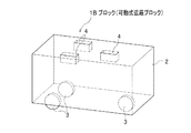
以下、図6〜図8を参照して、本実施形態2に係るブロック1Bの構成につき説明する。図6は、ブロック1Bの構成を示す図である。図7は、実施形態2に係るブロック1Bの主要部の配置例を示す図である。図8は、実施形態2に係るブロック1Bの設置例を示す図である。
Hereinafter, the configuration of the
図6に示すように、ブロック1Bは、3個の車輪3がブロック本体2の底面に設けられている。したがって、ブロック1Bは、3個の収容部5(図1参照)がブロック本体2の内部に設けられている。また、ブロック1Bは、3個の穴4がブロック本体2の内部に設けられている。このようなブロック1Bは、実施形態1に係るブロック1よりも、また、実施形態1の変形例に係るブロック1Aよりも、穴4及び収容部5の数が少ない。そのため、ブロック1Bは、ブロック1,1Aよりも、遮蔽体とみなせる領域が増加する。その結果、ブロック1Bは、ブロック1,1Aよりも、遮蔽欠損を減少させて、放射線遮蔽機能を向上させることができる。
As shown in FIG. 6, the
ただし、実施形態1に係るブロック1は、4個の車輪3を有している。また、実施形態1の変形例に係るブロック1Aは、6個の車輪3を有している。そのため、ブロック1,1Aは、3個の車輪3しか有していないブロック1Bよりも、安定した走行が可能となる。
However, the
図7は、ブロック1Bの主要部の配置例を示している。図7(a)は、ブロック本体2の底面側に設けられた車輪3の配置例を示しており、図7(b)は、ブロック本体2の上面側に設けられた穴4の配置例を示している。図7に示す例では、前記した通り、3個の車輪3がブロック本体2の底面に設けられおり、3個の穴4がブロック本体2の上面に設けられている。
FIG. 7 shows an arrangement example of the main part of the
図7(a)に示す例では、3個の車輪3が、ブロック本体2の底面の、ブロック本体2の横幅方向の中央でかつ縦幅方向の中央よりも上側の領域(以下、「中央上段の領域」と称する)、左下の領域、及び、右下の領域に、それぞれ1つずつ、配置されている。
In the example shown in FIG. 7A, the three
具体的には、中央上段の領域の車輪3は、その中心点C3が、中心線CL1の上で、かつ、中心線CL2から上方向に距離P1の位置になるように、配置されている。また、左下の領域の車輪3は、その中心点C3が、中心線CL1から左方向に距離T1の位置で、かつ、中心線CL2から下方向に距離P1の位置になるように、配置されている。また、右下の領域の車輪3は、その中心点C3が、中心線CL1から右方向に距離T1の位置で、かつ、中心線CL2から下方向に距離P1の位置になるように、配置されている。
Specifically, the
また、図7(b)に示す例では、3個の穴4が、ブロック本体2の上面の中央上段の領域、左下の領域、及び、右下の領域に、それぞれ1つずつ、配置されている。
In the example shown in FIG. 7B, three
具体的には、中央上段の領域の穴4は、その中心点C4が、中心線CL1の上で、かつ、中心線CL2から上方向に距離P2の位置になるように、配置されている。また、左下の領域の穴4は、その中心点C4が、中心線CL1から左方向に距離T1の位置で、かつ、中心線CL2から下方向に距離P2の位置になるように、配置されている。また、右下の領域の穴4は、その中心点C4が、中心線CL1から右方向に距離T1の位置で、かつ、中心線CL2から下方向に距離P2の位置になるように、配置されている。
Specifically, the
図8は、ブロック1Bの設置例を示している。図8(a)は、2個のブロック1Bがブロック1Gとして床面20の上に設置され、1個のブロック1Bがブロック1Uとしてそれらの2個のブロック1Gの上に集積配置される直前の状態を示している。また、図8(b)は、1個のブロック1Uが、2個のブロック1Gの上に集積配置された後の状態を示している。
FIG. 8 shows an installation example of the
図8に示すように、ブロック1Bは、下のブロック1B(図示例では、ブロック1G)と上のブロック1B(ブロック1U)とが、逆向きに配置される。すなわち、ブロック1Bは、上下方向の奇数列目のブロック1Bと上下方向の偶数列目のブロック1Bとが、逆向きに配置される。これにより、ブロック1Bは、上のブロック1Uの車輪3を下のブロック1Gの穴4に嵌め合わせることができる。
As shown in FIG. 8, in the
係る構成において、ブロック1Bは、前記した通り、ブロック1,1Aよりも、遮蔽欠損を減少させて、放射線遮蔽機能を向上させることができる。したがって、ブロック1Bは、ブロック1,1Aよりも、高い放射線の遮蔽効果を得ることができる。
ブロック1Bは、その他の効果については、ブロック1,1Aと同様である。
In such a configuration, as described above, the
The other effects of the
<変形例に係る可動式遮蔽ブロックの構成>
本実施形態2に係るブロック1Bは、穴4の配置位置を変更することができる。図9は、実施形態2の変形例に係るブロック1Cの構成を示している。図9(b)に示す例では、ブロック1Cは、実施形態2のブロック1B(図7(b)参照)と比較すると、穴4の配置位置が逆向きになっている。
<Configuration of movable shielding block according to modification>
In the
図9は、ブロック1Cの主要部の配置例を示している。図9(a)は、ブロック本体2の底面側に設けられた車輪3の配置例を示しており、図9(b)は、ブロック本体2の上面側に設けられた穴4の配置例を示している。図9に示す例では、ブロック1Cは、実施形態2のブロック1Bと同様に、3個の車輪3がブロック本体2の底面に設けられおり、3個の穴4がブロック本体2の上面に設けられている。
FIG. 9 shows an example of the arrangement of the main part of the
図9(a)に示すように、ブロック1Cは、車輪3が実施形態2のブロック1Bの車輪3と同じ位置に配置されている。
一方、図9(b)に示すように、ブロック1Cは、穴4が実施形態2のブロック1Bの穴4と長手方向の中心線CL2を中心にして逆の位置に配置されている。つまり、ブロック1Cは、ブロック本体2の上面の、左上の領域、右上の領域、及び、ブロック本体2の横幅方向の中央でかつ縦幅方向の中央よりも下側の領域(以下、「中央下段の領域」と称する)に、それぞれ1つずつ、配置されている。具体的には、左上の領域の穴4は、その中心点C4が、中心線CL1から左方向に距離T1の位置で、かつ、中心線CL2から上方向に距離P2の位置になるように、配置されている。また、右上の領域の穴4は、その中心点C4が、中心線CL1から右方向に距離T1の位置で、かつ、中心線CL2から上方向に距離P2の位置になるように、配置されている。また、中央下段の領域の穴4は、その中心点C4が、中心線CL1の上で、かつ、中心線CL2から下方向に距離P2の位置になるように、配置されている。
As shown to Fig.9 (a), as for the
On the other hand, as shown in FIG. 9B, in the
図10は、ブロック1Cの設置例を示している。図10(a)は、2個のブロック1Cがブロック1Gとして床面20の上に設置され、1個のブロック1Cがブロック1Uとしてそれらの2個のブロック1Gの上に集積配置される直前の状態を示している。また、図10(b)は、1個のブロック1Uが、2個のブロック1Gの上に集積配置された後の状態を示している。
FIG. 10 shows an installation example of the
図10に示すように、ブロック1Cは、下のブロック1B(図示例では、ブロック1G)と上のブロック1B(ブロック1U)とが、同じ向きに配置される。すなわち、ブロック1Cは、上下方向の奇数列目のブロック1Bと上下方向の偶数列目のブロック1Bとが、同じ向きに配置される。これにより、ブロック1Cは、上のブロック1Uの車輪3を下のブロック1Gの穴4に嵌め合わせることができる。
As shown in FIG. 10, in the
ブロック1Cは、ブロック1Bと比較すると、上のブロック1Uと下のブロック1Gとを一律に同じ向きで集積配置することができる。したがって、作業員は、ブロック本体2の上面に設けられた穴4のパターンに従って設置すればよい。そのため、ブロック1Cは、ブロック1Bよりも、容易に設置することができる。
In the
以上の通り、本実施形態2に係るブロック1B,1Cによれば、実施形態1に係るブロック1,1Aと同様に、作業員の負荷を軽減するとともに、短時間で遮蔽部材を搬送して設置することができる。
しかも、ブロック1B,1Cによれば、実施形態1に係るブロック1,1Aよりも、遮蔽欠損を減少させて、放射線遮蔽機能を向上させることができる。
As described above, according to the
In addition, according to the
[実施形態3]
本実施形態3では、ブロック1,1Aよりも、車輪3及び穴4の数を増加させたブロック1Dを提供する。
[Embodiment 3]
In the third embodiment, a
以下、図11及び図12を参照して、本実施形態3に係るブロック1Dの構成につき説明する。図11は、実施形態3に係る可動式遮蔽ブロック1Dの主要部の配置例を示す図である。図12は、実施形態3に係る可動式遮蔽ブロック1Dの設置例を示す図である。
The configuration of the
図11は、ブロック1Dの主要部の配置例を示している。図11(a)は、ブロック本体2の底面側に設けられた車輪3の配置例を示しており、図11(b)は、ブロック本体2の上面側に設けられた穴4の配置例を示している。
FIG. 11 shows an arrangement example of main parts of the
図11に示すように、ブロック1Dは、5個の車輪3がブロック本体2の底面に設けられており、5個の穴4がブロック本体2の上面に設けられている。
As shown in FIG. 11, in the
図11(a)に示す例では、5個の車輪3が、ブロック本体2の底面の、中央上段の領域、ブロック本体2の横幅方向の左側でかつ縦幅方向の中央の領域(以下、「左中段の領域」と称する)、ブロック本体2の横幅方向の右側でかつ縦幅方向の中央の領域(以下、「右中段の領域」と称する)、左下の領域、及び、右下の領域に、それぞれ1つずつ、配置されている。
In the example shown in FIG. 11 (a), five
具体的には、中央上段の領域の車輪3は、その中心点C3が、中心線CL1の上で、かつ、中心線CL2から上方向に距離P3の位置になるように、配置されている。また、左中段の領域の車輪3は、その中心点C3が、中心線CL1から左方向に距離T1の位置で、かつ、中心線CL2の上の位置になるように、配置されている。また、右中段の領域の車輪3は、その中心点C3が、中心線CL1から右方向に距離T1の位置で、かつ、中心線CL2の上の位置になるように、配置されている。また、左下の領域の車輪3は、その中心点C3が、中心線CL1から左方向に距離T1の位置で、かつ、中心線CL2から下方向に距離P3の位置になるように、配置されている。また、右下の領域の車輪3は、その中心点C3が、中心線CL1から右方向に距離T1の位置で、かつ、中心線CL2から下方向に距離P3の位置になるように、配置されている。
Specifically, the
なお、図11(a)に示す例では、「中心線CL2から上方向に距離P3の位置」は、ブロック本体2の前面(図11(a)中、上側の面)から距離P4の位置となっている。また、「中心線CL2から下方向に距離P3の位置」は、ブロック本体2の後面(図11(a)中、下側の面)から距離P4の位置となっている。距離P4の値は、距離P3の値の半分(すなわち、(1/2×P3))となっている。 In the example shown in FIG. 11A, the “position at a distance P3 upward from the center line CL2” is a position at a distance P4 from the front surface of the block body 2 (the upper surface in FIG. 11A). It has become. Further, “a position at a distance P3 downward from the center line CL2” is a position at a distance P4 from the rear surface of the block body 2 (the lower surface in FIG. 11A). The value of the distance P4 is half of the value of the distance P3 (that is, (1/2 × P3)).
また、図11(b)に示す例では、5個の穴4が、ブロック本体2の上面の、中央上段の領域、左中段の領域、右中段の領域、左下の領域、及び、右下の領域に、それぞれ1つずつ、配置されている。
Further, in the example shown in FIG. 11B, the five
具体的には、中央上段の領域の穴4は、その中心点C4が、中心線CL1の上で、かつ、中心線CL2から上方向に距離P3の位置になるように、配置されている。また、左中段の領域の穴4は、その中心点C4が、中心線CL1から左方向に距離T1の位置で、かつ、中心線CL2の上の位置になるように、配置されている。また、右中段の領域、の穴4は、その中心点C4が、中心線CL1から右方向に距離T1の位置で、かつ、中心線CL2の上の位置になるように、配置されている。また、左下の領域の穴4は、その中心点C4が、中心線CL1から左方向に距離T1の位置で、かつ、中心線CL2から下方向に距離P3の位置になるように、配置されている。また、右下の領域の穴4は、その中心点C4が、中心線CL1から右方向に距離T1の位置で、かつ、中心線CL2から下方向に距離P3の位置になるように、配置されている。
Specifically, the
図12は、ブロック1Dの設置例を示している。図12(a)は、2個のブロック1Dがブロック1Gとして床面20の上に設置され、1個のブロック1Dがブロック1Uとしてそれらの2個のブロック1Gの上に集積配置される直前の状態を示している。また、図12(b)は、1個のブロック1Uが、2個のブロック1Gの上に集積配置された後の状態を示している。
FIG. 12 shows an installation example of the
図12に示すように、ブロック1Dは、下のブロック1D(図示例では、ブロック1G)と上のブロック1D(ブロック1U)とが、逆向きに配置される。すなわち、ブロック1Dは、上下方向の奇数列目のブロック1Dと上下方向の偶数列目のブロック1Dとが、逆向きに配置される。そして、ブロック1Dは、上のブロック1Uの中央上段の車輪3が下のブロック1Gの中央上段の穴4に一致するように配置される。これにより、ブロック1Dは、上のブロック1Uの車輪3を下のブロック1Gの穴4に嵌め合わせることができる。
As shown in FIG. 12, in the
係る構成において、ブロック1Dは、車輪3の数が、実施形態1に係るブロック1,1Aよりも増加されている。そのため、ブロック1Dは、1個当たりの車輪3にかかる負荷を減少させることができる。その結果、ブロック1Dは、ブロック1,1Aよりも、車輪3の摩耗を抑制することができ、車輪3の寿命を延ばすことができる。
In such a configuration, in the
以上の通り、本実施形態3に係るブロック1Dによれば、実施形態1に係るブロック1,1Aと同様に、作業員の負荷を軽減するとともに、短時間で遮蔽部材を搬送して設置することができる。
しかも、ブロック1Dによれば、実施形態1に係るブロック1,1Aよりも、車輪3の寿命を延ばすことができる。
As described above, according to the
Moreover, according to the
[実施形態4(参考例)]
本実施形態4では、実施形態1〜3に係るブロック1,1A,1B,1C,1Dの下に敷設可能な床材30を提供する。ここでは、床材30の上にブロック1が設置される場合を想定して説明する。なお、本実施形態4は、参考例である。
[Embodiment 4 (reference example) ]
In the fourth embodiment, a
以下、図13を参照して、本実施形態4に係る床材30の構成につき説明する。図13は、実施形態4に係る床材を用いた場合の、可動式遮蔽ブロックの設置例を示す図である。図13(a)は、床材30が床面20の上に設置され、1個のブロック1が床材30の上に設置される直前の状態を示している。また、図8(b)は、3個のブロック1がブロック1Gとして床材30の上に設置された後の状態を示している。
Hereinafter, the configuration of the
図13(a)に示すように、床材30は、床面20上に敷設が可能なプレート状に形成されている。そして、床材30は、ブロック1の車輪3が嵌め込まれる穴31が、その上面に設けられている。穴31は、ブロック1に設けられた穴4(図3(b)参照)と同様の寸法に形成されている。また、穴31の深さは、車輪3のブロック本体2の底面からの突出量よりも若干大きな値に設定されている。したがって、床材30は、その穴31の深さよりも十分に厚くなるように形成されている。なお、床材30は、上に集積配置される多数のブロック1の荷重に耐えることが可能な強度を有する部材であることが好ましい。
As shown in FIG. 13A, the
図13(b)に示すように、ブロック1は、ブロック1Gとして床材30の上に設置される。このとき、ブロック1Gは、ブロック本体2の底面が床材30の上面に当接するため、安定した状態となる。したがって、床材30は、ブロック1を安定した状態で設置することができる。また、床材30は、地震の発生時に、ブロック1が振動によって移動するのを防止することができ、高い耐震性を得ることができる。
As shown in FIG.13 (b), the
なお、本実施形態4では、ブロック1Gは、車輪3が床材30の穴31に嵌め込まれる。そのため、床材30を用いる場合は、ブロック1からダンパー8等の付勢部材を削除することも可能である。
In the fourth embodiment, in the
以上の通り、本実施形態4に係る床材30によれば、実施形態1〜3に係るブロック1,1A,1B,1C,1Dを安定した状態で設置することができる。また、床材30によれば、地震の発生時に、実施形態1〜3に係るブロック1,1A,1B,1C,1Dが振動によって移動するのを防止することができ、高い耐震性を得ることができる。
As described above, according to the
本発明は、前記した実施形態に限定されるものではなく、様々な変形例が含まれる。例えば、前記した実施形態は、本発明を分かり易く説明するために詳細に説明したものであり、必ずしも説明した全ての構成を備えるものに限定されるものではない。また、ある実施形態の構成の一部を他の実施形態の構成に置き換えることが可能であり、また、ある実施形態の構成に他の実施形態の構成を加えることも可能である。また、各実施形態の構成の一部について、他の構成の追加・削除・置換をすることが可能である。 The present invention is not limited to the above-described embodiment, and includes various modifications. For example, the above-described embodiment has been described in detail for easy understanding of the present invention, and is not necessarily limited to one having all the configurations described. Further, a part of the configuration of an embodiment can be replaced with the configuration of another embodiment, and the configuration of another embodiment can be added to the configuration of an embodiment. In addition, it is possible to add, delete, and replace other configurations for a part of the configuration of each embodiment.
例えば、本発明は、原子力発電所に限らず、原子核や素粒子の実験に用いる加速器等の実験施設、医療施設等の、放射線に関連する様々な施設に用いることができる。
また、例えば、車輪3や穴4の数や位置は、任意に変更することができる。
また、例えば、実施形態1〜3に係るブロック1,1A,1B,1C,1Dは、環状のベルトを複数の車輪に張架させて、ベルトを無限軌道(クローラ)として用いることにより、移動する構成にしてもよい。このような無限軌道(クローラ)は、車輪に含まれるものである。また、本発明は、このような無限軌道(クローラ)を車輪の一例として含むものである。
また、例えば、実施形態4のように、ブロック1を、上面に穴31が設けられた床材30の上に積層配置する場合に、車輪3を押圧するダンパー8等の付勢部材を削除することができる。
For example, the present invention can be used not only in a nuclear power plant but also in various facilities related to radiation, such as an experimental facility such as an accelerator used for experiments of atomic nuclei and elementary particles, and a medical facility.
Further, for example, the number and positions of the
In addition, for example, the
Further, for example, as in the fourth embodiment, when the
なお、本発明に係るブロックは、前記した実施形態1に係るブロック1や実施形態1の変形例に係る1Aのように、偶数個の車輪3がブロック本体2の底面に設けられているとともに、偶数個の穴4がブロック本体2の上面に設けられている場合に、車輪3及び穴4が以下のように設けられているとよい。すなわち、車輪3は、それぞれ、ブロックの長手方向に所定のピッチで設けられているとともに、ブロックの短手方向に、短手方向の中心線CL1を中心にして線対称な位置に設けられているとよい。また、穴4は、上に積層配置される他のブロック1Uの車輪3と対向する位置に設けられているとよい。
In addition, the block according to the present invention is provided with an even number of
なお、本発明に係るブロックは、前記した実施形態2に係るブロック1Bや実施形態2の変形例に係るブロック1C、実施形態3に係るブロック1Dのように、奇数個の車輪3がブロック本体2の底面に設けられているとともに、奇数個の穴4がブロック本体2の上面に設けられている場合に、車輪3及び穴4が以下のように設けられているとよい。すなわち、車輪3は、それぞれ、ブロックの長手方向に所定のピッチで設けられているとともに、ブロックの短手方向に、短手方向の中心線CL1を中心にして線対称な位置に設けられているとよい。また、穴4は、上に積層配置される他のブロック1Uの車輪3と対向する位置に設けられているとよい。
The block according to the present invention includes an odd number of
この構成の場合に、本発明に係るブロックは、前記した実施形態2に係るブロック1Bや実施形態3に係るブロック1Dのように、車輪3の配置パターン及び穴4の配置パターンを設定してもよい。すなわち、車輪3の配置パターンは、短手方向の中心線CL1の上に設けられた1個の車輪3が他の車輪3よりも長手方向の端部に位置するパターンとなっており、また、穴4の配置パターンは、車輪3の配置パターンと同じ向きのパターンになっているようにしてもよい。
In the case of this configuration, the block according to the present invention can set the arrangement pattern of the
又は、この構成の場合に、本発明に係るブロックは、前記した実施形態2の変形例に係るブロック1Cのように、車輪3の配置パターン及び穴4の配置パターンを設定してもよい。すなわち、車輪3の配置パターンは、短手方向の中心線CL1の上に設けられた1個の車輪3が他の車輪3よりも長手方向の端部に位置するパターンとなっており、また、穴4の配置パターンは、車輪3の配置パターンと逆向きのパターンになっているようにしてもよい。
Alternatively, in the case of this configuration, the block according to the present invention may set the arrangement pattern of the
1(1G,1U),1A,1B,1C,1D ブロック(可動式遮蔽ブロック)
2 ブロック本体
3 車輪
4 穴
5 収容部
6 支持機構
7 車軸
8 バンパー(付勢部材)
20 床面
30 床材
31 穴
1 (1G, 1U), 1A, 1B, 1C, 1D block (movable shielding block)
2
20
Claims (9)
前記ブロック本体の底面に設けられ、前記ブロック本体を移動させる1乃至複数の車輪とを有し、
上に積層配置される他の可動式遮蔽ブロックの前記車輪が嵌め込まれる穴が、前記ブロック本体の上面に設けられている
ことを特徴とする可動式遮蔽ブロック。 A block main body having a radiation shielding function for shielding radiation and capable of stacking a plurality of layers vertically;
One or more wheels provided on the bottom surface of the block body and moving the block body;
A movable shielding block, wherein a hole into which the wheel of another movable shielding block arranged in a stack is fitted is provided on the upper surface of the block body.
前記収容部の内部に設けられ、前記車輪を回転自在な状態で上下方向に摺動可能に支持する支持機構とを有しており、
前記支持機構は、前記収容部に収容された前記車輪を、前記ブロック本体の前記底面よりも下側に押し出す付勢部材を備えており、
1個の前記付勢部材が1個の前記車輪を下側に押し出す押圧の値は、(1個の当該可動式遮蔽ブロックの荷重/前記車輪の数)よりも大きく、かつ、(1個の当該可動式遮蔽ブロックの荷重×1.5/前記車輪の数)未満に設定されている
ことを特徴とする請求項1に記載の可動式遮蔽ブロック。 An accommodation portion that is provided inside the block main body from the bottom toward the upper side, and accommodates the wheel;
A support mechanism that is provided inside the accommodating portion and supports the wheel so as to be slidable in a vertical direction in a rotatable state;
The support mechanism includes an urging member that pushes the wheel housed in the housing portion downward from the bottom surface of the block body,
The value of the pressing force by which one urging member pushes one wheel downward is larger than (the load of one movable shielding block / the number of the wheels) and (one 2. The movable shielding block according to claim 1, wherein the movable shielding block is set to be less than the load of the movable shielding block × 1.5 / the number of the wheels.
偶数個の前記穴が前記ブロック本体の前記上面に設けられており、
前記車輪は、それぞれ、当該可動式遮蔽ブロックの長手方向に所定のピッチで設けられているとともに、当該可動式遮蔽ブロックの短手方向に、短手方向の中心線を中心にして線対称な位置に設けられており、
前記穴は、上に積層配置される他の可動式遮蔽ブロックの前記車輪と対向する位置に設けられている
ことを特徴とする請求項1又は請求項2に記載の可動式遮蔽ブロック。 An even number of the wheels are provided on the bottom surface of the block body,
An even number of holes are provided in the top surface of the block body;
Each of the wheels is provided at a predetermined pitch in the longitudinal direction of the movable shielding block, and is symmetrical with respect to the short direction of the movable shielding block about the center line in the short direction. It is provided in
3. The movable shielding block according to claim 1, wherein the hole is provided at a position facing the wheel of another movable shielding block arranged in a stacked manner on the hole.
奇数個の前記穴が前記ブロック本体の前記上面に設けられており、
前記車輪は、それぞれ、当該可動式遮蔽ブロックの長手方向に所定のピッチで設けられているとともに、偶数個が当該可動式遮蔽ブロックの短手方向に短手方向の中心線を中心にして線対称な位置に設けられ、1個が短手方向の中心線の上に設けられており、
前記穴は、上に積層配置される他の可動式遮蔽ブロックの前記車輪と対向する位置に設けられている
ことを特徴とする請求項1又は請求項2に記載の可動式遮蔽ブロック。 An odd number of wheels are provided on the bottom surface of the block body,
An odd number of holes are provided in the upper surface of the block body;
Each of the wheels is provided at a predetermined pitch in the longitudinal direction of the movable shielding block, and an even number is symmetrical about the center line in the short direction in the short direction of the movable shielding block. Provided on the center line in the short direction,
3. The movable shielding block according to claim 1, wherein the hole is provided at a position facing the wheel of another movable shielding block arranged in a stacked manner on the hole.
前記穴の配置パターンは、前記車輪の配置パターンと同じ向きのパターンになっていることを特徴とする請求項4に記載の可動式遮蔽ブロック。 The arrangement pattern of the wheels is a pattern in which one of the wheels provided on the center line in the short direction is located at the end in the longitudinal direction than the other wheels,
The movable shielding block according to claim 4, wherein the hole arrangement pattern is a pattern in the same direction as the wheel arrangement pattern.
前記穴の配置パターンは、前記車輪の配置パターンと逆向きのパターンになっている
ことを特徴とする請求項4に記載の可動式遮蔽ブロック。 The arrangement pattern of the wheels is a pattern in which one of the wheels provided on the center line in the short direction is located at the end in the longitudinal direction than the other wheels,
The movable shielding block according to claim 4, wherein the arrangement pattern of the holes is a pattern opposite to the arrangement pattern of the wheels.
ことを特徴とする可動式遮蔽ブロックの積層構造。 The plurality of movable shielding blocks according to any one of claims 1 to 4 are stacked in a vertical direction in a state in which the positions are shifted in the longitudinal direction in each vertical row. A laminated structure of movable shielding blocks characterized by the above.
前記車輪は、それぞれ、当該可動式遮蔽ブロックの長手方向に所定のピッチで設けられているとともに、偶数個が当該可動式遮蔽ブロックの短手方向に短手方向の中心線を中心にして線対称な位置に設けられ、1個が短手方向の中心線の上に設けられており、
前記穴は、上に積層配置される他の可動式遮蔽ブロックの前記車輪と対向する位置に設けられており、
前記車輪の配置パターンは、短手方向の中心線の上に設けられた1個の前記車輪が他の車輪よりも長手方向の端部に位置するパターンとなっており、
前記穴の配置パターンは、前記車輪の配置パターンと同じ向きのパターンになっており、
複数個の当該可動式遮蔽ブロックが上下方向に積層配置される場合に、上下方向の奇数列目の可動式遮蔽ブロックと上下方向の偶数列目の可動式遮蔽ブロックとが、逆向きに配置される
ことを特徴とする請求項7に記載の可動式遮蔽ブロックの積層構造。 The movable shielding block has an odd number of wheels provided on the bottom surface of the block body and an odd number of holes provided on the top surface of the block body.
Each of the wheels is provided at a predetermined pitch in the longitudinal direction of the movable shielding block, and an even number is symmetrical about the center line in the short direction in the short direction of the movable shielding block. Provided on the center line in the short direction,
The hole is provided at a position facing the wheel of another movable shielding block that is stacked on the top,
The arrangement pattern of the wheels is a pattern in which one of the wheels provided on the center line in the short direction is located at the end in the longitudinal direction than the other wheels,
The hole arrangement pattern is a pattern in the same direction as the wheel arrangement pattern,
When a plurality of movable shielding blocks are stacked in the vertical direction, the movable shielding blocks in the odd-numbered rows in the vertical direction and the movable shielding blocks in the even-numbered rows in the vertical direction are arranged in opposite directions. The laminated structure of the movable shielding block according to claim 7.
前記車輪は、それぞれ、当該可動式遮蔽ブロックの長手方向に所定のピッチで設けられているとともに、偶数個が当該可動式遮蔽ブロックの短手方向に短手方向の中心線を中心にして線対称な位置に設けられ、1個が短手方向の中心線の上に設けられており、
前記穴は、上に積層配置される他の可動式遮蔽ブロックの前記車輪と対向する位置に設けられており、
前記車輪の配置パターンは、短手方向の中心線の上に設けられた1個の前記車輪が他の車輪よりも長手方向の端部に位置するパターンとなっており、
前記穴の配置パターンは、前記車輪の配置パターンと逆向きのパターンになっており、
複数個の当該可動式遮蔽ブロックが上下方向に積層配置される場合に、上下方向の奇数列目の可動式遮蔽ブロックと上下方向の偶数列目の可動式遮蔽ブロックとが、同じ向きに配置される
ことを特徴とする請求項7に記載の可動式遮蔽ブロックの積層構造。 The movable shielding block has an odd number of wheels provided on the bottom surface of the block body and an odd number of holes provided on the top surface of the block body.
Each of the wheels is provided at a predetermined pitch in the longitudinal direction of the movable shielding block, and an even number is symmetrical about the center line in the short direction in the short direction of the movable shielding block. Provided on the center line in the short direction,
The hole is provided at a position facing the wheel of another movable shielding block that is stacked on the top,
The arrangement pattern of the wheels is a pattern in which one of the wheels provided on the center line in the short direction is located at the end in the longitudinal direction than the other wheels,
The hole arrangement pattern is a pattern opposite to the wheel arrangement pattern,
When a plurality of movable shielding blocks are stacked in the vertical direction, the odd-numbered movable shielding blocks in the vertical direction and the movable shielding blocks in the even-numbered rows in the vertical direction are arranged in the same direction. The laminated structure of the movable shielding block according to claim 7.
Priority Applications (1)
| Application Number | Priority Date | Filing Date | Title |
|---|---|---|---|
| JP2013086745A JP6085214B2 (en) | 2013-04-17 | 2013-04-17 | Movable shielding block and laminated structure of movable shielding block |
Applications Claiming Priority (1)
| Application Number | Priority Date | Filing Date | Title |
|---|---|---|---|
| JP2013086745A JP6085214B2 (en) | 2013-04-17 | 2013-04-17 | Movable shielding block and laminated structure of movable shielding block |
Publications (3)
| Publication Number | Publication Date |
|---|---|
| JP2014211329A JP2014211329A (en) | 2014-11-13 |
| JP2014211329A5 JP2014211329A5 (en) | 2016-05-12 |
| JP6085214B2 true JP6085214B2 (en) | 2017-02-22 |
Family
ID=51931196
Family Applications (1)
| Application Number | Title | Priority Date | Filing Date |
|---|---|---|---|
| JP2013086745A Active JP6085214B2 (en) | 2013-04-17 | 2013-04-17 | Movable shielding block and laminated structure of movable shielding block |
Country Status (1)
| Country | Link |
|---|---|
| JP (1) | JP6085214B2 (en) |
Family Cites Families (6)
| Publication number | Priority date | Publication date | Assignee | Title |
|---|---|---|---|---|
| JPS55121816U (en) * | 1979-02-21 | 1980-08-29 | ||
| JPH0610897U (en) * | 1991-04-26 | 1994-02-10 | 三菱電機株式会社 | Radiation shielding structure |
| JP2807978B2 (en) * | 1995-04-28 | 1998-10-08 | 株式会社朝日コーポレーション | Traveling block and block toy using the same |
| JP3121265B2 (en) * | 1996-05-07 | 2000-12-25 | 株式会社日立製作所 | Radiation shield |
| JP2002214387A (en) * | 2001-01-18 | 2002-07-31 | Ishikawajima Harima Heavy Ind Co Ltd | Opening/closing structure of opening in nuclear energy facility |
| JP4600782B2 (en) * | 2007-10-26 | 2010-12-15 | Necアクセステクニカ株式会社 | Robot anti-theft system |
-
2013
- 2013-04-17 JP JP2013086745A patent/JP6085214B2/en active Active
Also Published As
| Publication number | Publication date |
|---|---|
| JP2014211329A (en) | 2014-11-13 |
Similar Documents
| Publication | Publication Date | Title |
|---|---|---|
| US20170152105A1 (en) | Horizontal storage module, carriage assembly, and canister transfer assemblies | |
| TW201311526A (en) | Automatic warehouse rack apparatus | |
| JP2013007640A (en) | Assembly radioactive ray shield and radioactive ray shielding method by using the same | |
| JP6085214B2 (en) | Movable shielding block and laminated structure of movable shielding block | |
| JP2015206200A (en) | Construction method and construction device of shield tunnel | |
| JP2014031820A (en) | Pipe introduction device and pipe introduction method | |
| JP6484443B2 (en) | Heavy goods transportation and lifting system | |
| JP3181434U (en) | Fence-shaped radiation shielding sheet mounting jig and fence-shaped radiation shielding sheet mounting jig equipped with radiation shielding sheet | |
| JP6008176B2 (en) | Radioactive waste storage structure and storage method thereof | |
| CN107433822A (en) | A kind of unmanned truck damping device | |
| JP2021025246A (en) | Planer-type main rope support | |
| US9211666B2 (en) | Injection molding machine containing transformer | |
| JP5940404B2 (en) | Construction method of beam members | |
| JP2008233176A (en) | Seismic isolation experiencing equipment | |
| JP6691632B1 (en) | Landfill landfill system and landfill method | |
| JP5832484B2 (en) | Storage rack | |
| JP6467951B2 (en) | Seismic isolation system | |
| JP6053388B2 (en) | Radiation shielding material storage container and radiation shielding system | |
| JP2014227767A (en) | Rockfall prevention fence | |
| JP6302252B2 (en) | Building equipment mounting method and building manufacturing method | |
| JP2016139638A (en) | Transformer | |
| JP2014181979A (en) | Suspension/storage tool for radioactive contaminant solidified body | |
| JP6296498B2 (en) | Seismic isolation method for automatic warehouse racks | |
| JP6399868B2 (en) | Seismic isolation system for automatic warehouse racks | |
| JP6668117B2 (en) | Shelf equipment |
Legal Events
| Date | Code | Title | Description |
|---|---|---|---|
| A521 | Written amendment |
Free format text: JAPANESE INTERMEDIATE CODE: A523 Effective date: 20160318 |
|
| A621 | Written request for application examination |
Free format text: JAPANESE INTERMEDIATE CODE: A621 Effective date: 20160318 |
|
| RD02 | Notification of acceptance of power of attorney |
Free format text: JAPANESE INTERMEDIATE CODE: A7422 Effective date: 20160622 |
|
| A131 | Notification of reasons for refusal |
Free format text: JAPANESE INTERMEDIATE CODE: A131 Effective date: 20161101 |
|
| A521 | Written amendment |
Free format text: JAPANESE INTERMEDIATE CODE: A523 Effective date: 20161125 |
|
| A131 | Notification of reasons for refusal |
Free format text: JAPANESE INTERMEDIATE CODE: A131 Effective date: 20161213 |
|
| A521 | Written amendment |
Free format text: JAPANESE INTERMEDIATE CODE: A523 Effective date: 20170116 |
|
| TRDD | Decision of grant or rejection written | ||
| A01 | Written decision to grant a patent or to grant a registration (utility model) |
Free format text: JAPANESE INTERMEDIATE CODE: A01 Effective date: 20170124 |
|
| A61 | First payment of annual fees (during grant procedure) |
Free format text: JAPANESE INTERMEDIATE CODE: A61 Effective date: 20170127 |
|
| R150 | Certificate of patent or registration of utility model |
Ref document number: 6085214 Country of ref document: JP Free format text: JAPANESE INTERMEDIATE CODE: R150 |