JP6084635B2 - Water treatment system - Google Patents
Water treatment system Download PDFInfo
- Publication number
- JP6084635B2 JP6084635B2 JP2014554240A JP2014554240A JP6084635B2 JP 6084635 B2 JP6084635 B2 JP 6084635B2 JP 2014554240 A JP2014554240 A JP 2014554240A JP 2014554240 A JP2014554240 A JP 2014554240A JP 6084635 B2 JP6084635 B2 JP 6084635B2
- Authority
- JP
- Japan
- Prior art keywords
- raw water
- pressure resistance
- membrane module
- membrane
- tubular
- Prior art date
- Legal status (The legal status is an assumption and is not a legal conclusion. Google has not performed a legal analysis and makes no representation as to the accuracy of the status listed.)
- Active
Links
- XLYOFNOQVPJJNP-UHFFFAOYSA-N water Substances O XLYOFNOQVPJJNP-UHFFFAOYSA-N 0.000 title claims description 287
- 239000012528 membrane Substances 0.000 claims description 348
- 239000007788 liquid Substances 0.000 claims description 50
- 238000001914 filtration Methods 0.000 claims description 28
- 238000001514 detection method Methods 0.000 claims description 13
- 238000011144 upstream manufacturing Methods 0.000 claims description 11
- 239000008239 natural water Substances 0.000 claims description 8
- 230000008859 change Effects 0.000 claims description 5
- 239000002893 slag Substances 0.000 description 15
- 238000004140 cleaning Methods 0.000 description 14
- 238000012360 testing method Methods 0.000 description 13
- 230000000694 effects Effects 0.000 description 9
- 238000010586 diagram Methods 0.000 description 8
- 238000000034 method Methods 0.000 description 7
- 239000006185 dispersion Substances 0.000 description 6
- 230000000052 comparative effect Effects 0.000 description 5
- 239000011800 void material Substances 0.000 description 4
- 230000001133 acceleration Effects 0.000 description 3
- 238000005452 bending Methods 0.000 description 3
- 238000002347 injection Methods 0.000 description 3
- 239000007924 injection Substances 0.000 description 3
- 241000220317 Rosa Species 0.000 description 2
- 230000003247 decreasing effect Effects 0.000 description 2
- 230000004907 flux Effects 0.000 description 2
- 230000014509 gene expression Effects 0.000 description 2
- 238000004519 manufacturing process Methods 0.000 description 2
- 239000000463 material Substances 0.000 description 2
- 238000011160 research Methods 0.000 description 2
- 238000000926 separation method Methods 0.000 description 2
- 239000007787 solid Substances 0.000 description 2
- 239000002033 PVDF binder Substances 0.000 description 1
- 238000011001 backwashing Methods 0.000 description 1
- 230000008901 benefit Effects 0.000 description 1
- 230000007423 decrease Effects 0.000 description 1
- 238000011156 evaluation Methods 0.000 description 1
- 230000004048 modification Effects 0.000 description 1
- 238000012986 modification Methods 0.000 description 1
- 229920002981 polyvinylidene fluoride Polymers 0.000 description 1
- 230000009467 reduction Effects 0.000 description 1
- 239000010802 sludge Substances 0.000 description 1
- 238000003860 storage Methods 0.000 description 1
- 238000000967 suction filtration Methods 0.000 description 1
- 238000005406 washing Methods 0.000 description 1
- 238000004804 winding Methods 0.000 description 1
Images


Classifications
-
- B—PERFORMING OPERATIONS; TRANSPORTING
- B01—PHYSICAL OR CHEMICAL PROCESSES OR APPARATUS IN GENERAL
- B01D—SEPARATION
- B01D63/00—Apparatus in general for separation processes using semi-permeable membranes
- B01D63/06—Tubular membrane modules
- B01D63/066—Tubular membrane modules with a porous block having membrane coated passages
-
- B—PERFORMING OPERATIONS; TRANSPORTING
- B01—PHYSICAL OR CHEMICAL PROCESSES OR APPARATUS IN GENERAL
- B01D—SEPARATION
- B01D65/00—Accessories or auxiliary operations, in general, for separation processes or apparatus using semi-permeable membranes
- B01D65/02—Membrane cleaning or sterilisation ; Membrane regeneration
-
- C—CHEMISTRY; METALLURGY
- C02—TREATMENT OF WATER, WASTE WATER, SEWAGE, OR SLUDGE
- C02F—TREATMENT OF WATER, WASTE WATER, SEWAGE, OR SLUDGE
- C02F1/00—Treatment of water, waste water, or sewage
- C02F1/001—Processes for the treatment of water whereby the filtration technique is of importance
-
- B—PERFORMING OPERATIONS; TRANSPORTING
- B01—PHYSICAL OR CHEMICAL PROCESSES OR APPARATUS IN GENERAL
- B01D—SEPARATION
- B01D2313/00—Details relating to membrane modules or apparatus
- B01D2313/24—Specific pressurizing or depressurizing means
-
- B—PERFORMING OPERATIONS; TRANSPORTING
- B01—PHYSICAL OR CHEMICAL PROCESSES OR APPARATUS IN GENERAL
- B01D—SEPARATION
- B01D2313/00—Details relating to membrane modules or apparatus
- B01D2313/26—Specific gas distributors or gas intakes
-
- C—CHEMISTRY; METALLURGY
- C02—TREATMENT OF WATER, WASTE WATER, SEWAGE, OR SLUDGE
- C02F—TREATMENT OF WATER, WASTE WATER, SEWAGE, OR SLUDGE
- C02F1/00—Treatment of water, waste water, or sewage
- C02F1/44—Treatment of water, waste water, or sewage by dialysis, osmosis or reverse osmosis
-
- C—CHEMISTRY; METALLURGY
- C02—TREATMENT OF WATER, WASTE WATER, SEWAGE, OR SLUDGE
- C02F—TREATMENT OF WATER, WASTE WATER, SEWAGE, OR SLUDGE
- C02F2209/00—Controlling or monitoring parameters in water treatment
- C02F2209/03—Pressure
-
- C—CHEMISTRY; METALLURGY
- C02—TREATMENT OF WATER, WASTE WATER, SEWAGE, OR SLUDGE
- C02F—TREATMENT OF WATER, WASTE WATER, SEWAGE, OR SLUDGE
- C02F2209/00—Controlling or monitoring parameters in water treatment
- C02F2209/40—Liquid flow rate
-
- C—CHEMISTRY; METALLURGY
- C02—TREATMENT OF WATER, WASTE WATER, SEWAGE, OR SLUDGE
- C02F—TREATMENT OF WATER, WASTE WATER, SEWAGE, OR SLUDGE
- C02F2303/00—Specific treatment goals
- C02F2303/16—Regeneration of sorbents, filters
Landscapes
- Chemical & Material Sciences (AREA)
- Chemical Kinetics & Catalysis (AREA)
- Life Sciences & Earth Sciences (AREA)
- Hydrology & Water Resources (AREA)
- Engineering & Computer Science (AREA)
- Environmental & Geological Engineering (AREA)
- Water Supply & Treatment (AREA)
- Organic Chemistry (AREA)
- Separation Using Semi-Permeable Membranes (AREA)
Description
本発明は、水処理システムに関する。 The present invention relates to a water treatment system.
膜モジュールを用いて原水の水処理を行う水処理システムとして、様々なものが知られている。例えば、膜モジュールとして複数の管状膜を有するものを用い、原水を膜モジュールで吸引濾過して固液分離を行うものが知られている。膜モジュールの管状膜によって濾過された処理水は貯留槽に回収され、膜モジュールで濾過されずに通過した原水は水源に戻される。また、例えば、特許文献1に示すように、原水に空気を混合し、気液混相流とした原水を膜モジュールに流して水処理を行っている。
Various water treatment systems that perform raw water treatment using membrane modules are known. For example, a membrane module having a plurality of tubular membranes and performing solid-liquid separation by suction filtration of raw water through the membrane module is known. The treated water filtered by the tubular membrane of the membrane module is collected in a storage tank, and the raw water that has passed without being filtered by the membrane module is returned to the water source. For example, as shown in
ここで、上述のような水処理システムで用いられる膜モジュールは、数十本から数百本の管状膜で構成されている。そのような膜モジュールに対して、原水に空気を混合した気液混相流を流す場合、膜モジュール内の多数の管状膜に均一に原水と空気が流れず、中には管状膜に空気が詰まることにより原水が全く流れないものも発生する。このように、原水が流れない管状膜が発生すると、実質的に濾過に寄与する管状膜の本数が減ることによって濾過効率が低下することに加え、吸引圧力によって付着した固体が乾燥することにより、管状膜の寿命が縮まるという問題が発生する。 Here, the membrane module used in the water treatment system as described above is composed of tens to hundreds of tubular membranes. When a gas-liquid mixed phase flow in which air is mixed with raw water flows through such a membrane module, the raw water and air do not flow uniformly through a number of tubular membranes in the membrane module, and the tubular membrane is clogged with air. In some cases, raw water does not flow at all. Thus, when a tubular membrane in which raw water does not flow is generated, the filtration efficiency is lowered by reducing the number of tubular membranes that substantially contribute to filtration, and the solid adhered by the suction pressure is dried, There arises a problem that the lifetime of the tubular membrane is shortened.
このような問題は、膜洗浄効果の高い気泡投入比率を保ちながら、動力削減のために原水の流速を小さくした場合に発生し易い。従って、空気量を少なくすると共に所定速度以上の流速で運転することによって、流速の勢いで気泡が管状膜中に詰まらないようにする方法が考えられる。しかしながら、当該方法を採用したとしても、複数の管状膜に均一に流すことができない場合がある。また、当該方法では、膜洗浄効果を高めることが出来ず、高い動力が必要となるという問題がある。 Such a problem is likely to occur when the flow rate of the raw water is reduced in order to reduce power while maintaining the bubble injection ratio with a high membrane cleaning effect. Therefore, it is conceivable to reduce the amount of air and operate at a flow rate equal to or higher than a predetermined speed so that bubbles are not clogged in the tubular membrane due to the momentum of the flow rate. However, even if this method is adopted, it may not be possible to uniformly flow through the plurality of tubular membranes. Further, this method has a problem that the film cleaning effect cannot be enhanced and high power is required.
本発明は、このような課題を解決するためになされたものであり、高い膜洗浄効率を保ちつつ、低い動力にて、複数の管状膜に均一に気液混相流の原水を流すことのできる水処理システムを提供することを目的とする。 The present invention has been made in order to solve such a problem, and can uniformly feed raw water of a gas-liquid mixed phase flow to a plurality of tubular membranes with low power while maintaining high membrane cleaning efficiency. The object is to provide a water treatment system.
ここで、本発明者らは、鋭意研究の結果、次の知見を見出すに至った。すなわち、本発明者らは、原水が通過するライン上の圧力抵抗を適切に高めることによって、膜モジュールの複数の管状膜に均一に気液混相流の原水を流すことができることを見出した。また、本発明者らは、当該方法によって、原水の循環速度を高くすることなく、且つ、空気量を少なくすることなく、複数の管状膜に原水を均一に流すことができることを見出した。 Here, as a result of intensive studies, the present inventors have found the following knowledge. That is, the present inventors have found that by appropriately increasing the pressure resistance on the line through which the raw water passes, the raw water in a gas-liquid mixed phase flow can be flowed uniformly through the plurality of tubular membranes of the membrane module. In addition, the present inventors have found that the raw water can be made to uniformly flow through a plurality of tubular membranes without increasing the circulation rate of the raw water and reducing the amount of air.
そこで、本発明の一形態に係る水処理システムは、複数の管状膜を有し、管状膜の内部に原水を流して原水を濾過する膜モジュールと、原水の水源から膜モジュールへ原水を供給する原水供給部と、原水に気体を供給し、膜モジュールに供給される原水を気液混相流とする気体供給部と、少なくとも膜モジュールで濾過を行っているときに、原水に対する圧力抵抗が高められる圧力抵抗調整部と、を備え、圧力抵抗調整部は、原水供給部の下流側、又は原水供給部の上流側に設けられる。 Therefore, a water treatment system according to one embodiment of the present invention has a plurality of tubular membranes, a membrane module that flows raw water through the tubular membrane and filters the raw water, and supplies raw water from the raw water source to the membrane module. When the raw water supply unit, the gas supply unit that supplies gas to the raw water and uses the raw water supplied to the membrane module as a gas-liquid mixed phase flow, and at least the membrane module performs filtration, the pressure resistance to the raw water is increased. A pressure resistance adjusting unit, and the pressure resistance adjusting unit is provided downstream of the raw water supply unit or upstream of the raw water supply unit.
本発明の一形態に係る水処理システムは、少なくとも膜モジュールで濾過を行っているときに、原水に対する圧力抵抗が高められる圧力抵抗調整部を備えている。複数の管状膜の内部を気液混相流の原水が流れる時に管状膜間で圧力変動のばらつきが生じるとしても、当該圧力変動のばらつきの影響を無視できるように圧力抵抗調整部で圧力抵抗を高めることによって、圧力変動のばらつきに起因する不安定な原水の流れを抑制することができる。従って、膜モジュールが多数の管状膜を有している場合であっても、気液混相流の原水は各管状膜を均一に流れることができる。更に、膜洗浄効率を高くするために空気量を多くし、且つ、動力削減のために流速を小さくした場合であっても、気液混相流の原水は、各管状膜を均一に流れることができる。以上によって、水処理システムは、高い膜洗浄効率を保ちつつ、低い動力にて、複数の管状膜に均一に気液混相流の原水を流すことができる。 The water treatment system according to an aspect of the present invention includes a pressure resistance adjusting unit that can increase the pressure resistance with respect to raw water when at least the membrane module performs filtration. Even if there is a variation in pressure fluctuation between the tubular membranes when the raw water of gas-liquid mixed phase flows through the inside of multiple tubular membranes, the pressure resistance adjustment unit increases the pressure resistance so that the influence of the variation in the pressure fluctuation can be ignored By this, the unstable raw | natural water flow resulting from the dispersion | variation in a pressure fluctuation can be suppressed. Therefore, even when the membrane module has a large number of tubular membranes, the raw water of the gas-liquid mixed phase flow can flow uniformly through each tubular membrane. Furthermore, even when the amount of air is increased to increase the membrane cleaning efficiency and the flow rate is decreased to reduce power, the raw water of the gas-liquid mixed phase flow can flow uniformly through each tubular membrane. it can. As described above, the water treatment system can flow the gas-liquid mixed phase raw water uniformly to the plurality of tubular membranes with low power while maintaining high membrane cleaning efficiency.
圧力抵抗調整部は、膜モジュールの複数の管状膜のそれぞれに対して設けられてよい。これによって、気液混相流の原水は、より確実に各管状膜を均一に流れることができる。 The pressure resistance adjusting unit may be provided for each of the plurality of tubular membranes of the membrane module. Thereby, the raw water of the gas-liquid mixed phase flow can flow through each tubular membrane more reliably.
原水供給部は、少なくとも膜モジュールにおける原水の流速が0.05〜0.25m/sとなるように、原水を供給してよい。このように流速を小さくすることによって動力を削減することができる。 The raw water supply unit may supply the raw water so that at least the flow rate of the raw water in the membrane module is 0.05 to 0.25 m / s. Thus, power can be reduced by reducing the flow velocity.
水処理システムは、少なくとも、膜モジュールの入口側の圧力を検出する圧力検出部と、原水供給部、気体供給部、及び圧力抵抗調整部を制御する制御部と、を更に備え、圧力抵抗調整部は、弁の開閉によって圧力抵抗を変更可能であり、制御部は、圧力検出部の検出値に基づいて、原水供給部及び気体供給部を制御すると共に、圧力抵抗調整部で圧力抵抗を設定してよい。これによって、制御部は、圧力検出部の検出値を取得することで、膜モジュールの入口側の圧力に基づいて、圧力抵抗調整部の圧力抵抗を設定することができる。従って、制御部は、気液混相流の原水が複数の管状膜を均一に流れ易い条件となるように、圧力抵抗を設定することが可能となる。 The water treatment system further includes at least a pressure detection unit that detects the pressure on the inlet side of the membrane module, and a control unit that controls the raw water supply unit, the gas supply unit, and the pressure resistance adjustment unit, and the pressure resistance adjustment unit The pressure resistance can be changed by opening and closing the valve, and the control unit controls the raw water supply unit and the gas supply unit based on the detection value of the pressure detection unit, and sets the pressure resistance with the pressure resistance adjustment unit. It's okay. Thereby, the control unit can set the pressure resistance of the pressure resistance adjusting unit based on the pressure on the inlet side of the membrane module by acquiring the detection value of the pressure detecting unit. Therefore, the control unit can set the pressure resistance so that the raw water of the gas-liquid mixed phase flow can easily flow through the plurality of tubular membranes.
本発明の一形態に係る水処理システムは、複数の管状膜を有し、管状膜の内部に原水を流して原水を濾過する膜モジュールと、原水の水源から膜モジュールへ原水を供給する原水供給部と、原水に気体を供給し、膜モジュールに供給される原水を気液混相流とする気体供給部と、少なくとも膜モジュールで濾過を行っているときに、原水に対する圧力抵抗が高められる圧力抵抗調整部と、を備え、圧力抵抗調整部は、原水供給部の下流側、又は原水供給部の上流側に設けられ、原水供給部は、少なくとも膜モジュールにおける原水の流速が0.05〜0.25m/sとなるように、原水を供給し、圧力抵抗調整部は、膜モジュールでの圧力損失が100mmAq以上となるように設定される。 A water treatment system according to an aspect of the present invention includes a membrane module that has a plurality of tubular membranes, and flows raw water through the tubular membrane to filter the raw water, and raw water supply that supplies raw water from the raw water source to the membrane module A gas supply unit that supplies gas to the raw water and uses the raw water supplied to the membrane module as a gas-liquid mixed phase flow, and a pressure resistance that increases the pressure resistance against the raw water when filtering at least with the membrane module The pressure resistance adjustment unit is provided on the downstream side of the raw water supply unit or on the upstream side of the raw water supply unit, and the raw water supply unit has a raw water flow rate of at least 0.05 to 0.00 in the membrane module. The raw water is supplied so as to be 25 m / s, and the pressure resistance adjusting unit is set so that the pressure loss in the membrane module is 100 mmAq or more.
本発明の一形態に係る水処理システムは、少なくとも膜モジュールで濾過を行っているときに、原水に対する圧力抵抗が高められる圧力抵抗調整部を備えている。複数の管状膜の内部を気液混相流の原水が流れる時に管状膜間で圧力変動のばらつきが生じるとしても、当該圧力変動のばらつきの影響を無視できるように圧力抵抗調整部が、膜モジュールでの圧力損失が100mmAq以上となるように設定されることによって、圧力変動のばらつきに起因する不安定な原水の流れを抑制することができる。従って、膜モジュールが多数の管状膜を有している場合であっても、気液混相流の原水は各管状膜を均一に流れることができる。更に、膜洗浄効率を高くするために空気量を多くし、且つ、動力削減のために流速を小さくした場合(少なくとも膜モジュールにおける原水の流速が0.05〜0.25m/s)であっても、気液混相流の原水は、各管状膜を均一に流れることができる。以上によって、水処理システムは、高い膜洗浄効率を保ちつつ、低い動力にて、複数の管状膜に均一に気液混相流の原水を流すことができる。 The water treatment system according to an aspect of the present invention includes a pressure resistance adjusting unit that can increase the pressure resistance with respect to raw water when at least the membrane module performs filtration. Even if pressure fluctuation variability occurs between the tubular membranes when the raw water of gas-liquid mixed phase flows through the inside of the plurality of tubular membranes, the pressure resistance adjustment unit is installed in the membrane module so that the influence of the pressure fluctuation variability can be ignored. By setting the pressure loss to be 100 mmAq or more, it is possible to suppress an unstable flow of raw water due to variations in pressure fluctuation. Therefore, even when the membrane module has a large number of tubular membranes, the raw water of the gas-liquid mixed phase flow can flow uniformly through each tubular membrane. Furthermore, when the amount of air is increased to increase the membrane cleaning efficiency and the flow rate is reduced to reduce power (at least the flow rate of raw water in the membrane module is 0.05 to 0.25 m / s) However, the raw water of the gas-liquid mixed phase flow can flow uniformly through each tubular membrane. As described above, the water treatment system can flow the gas-liquid mixed phase raw water uniformly to the plurality of tubular membranes with low power while maintaining high membrane cleaning efficiency.
本発明によれば、高い膜洗浄効率を保ちつつ、低い動力にて、複数の管状膜に均一に気液混相流を流すことができる。 ADVANTAGE OF THE INVENTION According to this invention, a gas-liquid mixed phase flow can be uniformly flowed through several tubular membranes with low motive power, maintaining a high membrane washing | cleaning efficiency.
以下、添付図面を参照しながら本発明による水処理システムの一実施形態を詳細に説明する。なお、図面の説明において同一の要素には同一の符号を付し、重複する説明を省略する。 Hereinafter, an embodiment of a water treatment system according to the present invention will be described in detail with reference to the accompanying drawings. In the description of the drawings, the same elements are denoted by the same reference numerals, and redundant description is omitted.
[第1実施形態]
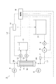
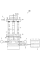
図1は、第1実施形態に係る水処理システム1を示す概略構成図である。図1に示すように、水処理システム1は、膜モジュール2と、原水槽(原水の水源)3と、原水ポンプ(原水供給部)4と、流量計6と、空気ブロワ(気体供給部)7と、圧力計(圧力検出部)8,9と、濾過水槽11と、濾過ポンプ12と、逆洗ポンプ13と、圧力抵抗調整部14と、制御部16と、を備えている。膜モジュール2よりも上流側では、原水槽3と膜モジュール2とは、ラインL1で接続されている。膜モジュール2よりも下流側では、原水槽3と膜モジュール2とは、ラインL2で接続されている。[First Embodiment]
膜モジュール2は、原水を濾過して固液分離するためのモジュールである。膜モジュール2は、複数のチューブラー膜(管状膜)5を有している。膜モジュール2は、複数のチューブラー膜5を束ねた状態で円筒状のケース10に収容することによって構成されている。膜モジュール2は、チューブラー膜5の内部に原水を流して当該原水を濾過する。チューブラー膜5は、内径が3〜20mm程度で、長さが50〜300cm程度のストロー状の膜であり、材質として、例えば、PVDF、PEなどが挙げられる。一つ当りの膜モジュール2は、50〜1000本のチューブラー膜5を有している。ただし、これらの内径、長さ、本数は一例であって、この数値に限定されるものではなく、当該範囲より小さくてもよく、大きくてもよい。また、材質も一例であって、限定されない。
The
原水槽3は、水処理システム1で処理される原水を貯留する槽である。なお、原水の水源は、原水槽3に代えて、河川などであってもよい。この場合、ラインL1は、河川から直接原水を吸い上げ、ラインL2は、膜モジュール2を通過した原水を河川へ排出する。原水ポンプ4は、ラインL1に設けられており、原水槽3から原水を吸引し、膜モジュール2に供給する。なお、原水ポンプ4の配置は特に限定されず、ラインL1,L2の何れかの位置に設けられている。流量計6は、ラインL1上に設けられ、原水ポンプ4で圧送される原水の流量を測定する。
The
空気ブロワ7は、原水に空気を供給し、膜モジュール2に供給される原水を気液混相流とする。空気ブロワ7は、ラインL1上であって、原水ポンプ4と膜モジュール2との間に設けられているが、膜モジュール2より上流側であれば、特に位置は限定されない。圧力計8は、膜モジュール2の上流側の圧力、具体的には、膜モジュール2の入口の直前の圧力を検出する。圧力計9は、膜モジュール2の下流側の圧力、具体的には、膜モジュール2の出口の直後の圧力を検出する。例えば、原水の流れがスラグ流である場合の空気の供給量は、0.05〜0.5m/sとすることができる。ただし、当該範囲で運転すれば、本システムのメリットが特に大きくなるものであるため、当該範囲に限定されるものではなく、例えば、1.0m/sや2.0m/sやそれ以上の供給量で運転してもよい。なお、ボイド率が0.1〜0.7程度(後述の試験においては0.4)でスラグ流になるため、空気の供給量を算出するためには、「ボイド率≒空気流速/(空気流速+水流速)」という式を用い、その領域になるように空気流速(空気の供給量)を設定してよい。例えば、水流速を動力削減のために、0.1m/sとする場合、ボイド率を0.4にするには空気の供給量を約0.065m/sとする。
The
膜モジュール2のチューブラー膜5を流れる原水の流れは、小さな気泡が上昇していくバブル流であってもよく、潰れたような状態の縦長で弾丸状の気泡が形成されるスラグ流であってもよく、スラグ流から大小様々な気泡が混在するチャーン流であってもよい。
The flow of raw water flowing through the
濾過水槽11は、膜モジュール2のチューブラー膜5によって固液分離された処理水を貯留する槽である。濾過ポンプ12は、ケース10に接続されており、チューブラー膜5の外側から原水を吸引するためのポンプである。これによって、濾過ポンプ12は、チューブラー膜5で固液分離されてケース10内に流出する処理水を濾過水槽11へ供給する。逆洗ポンプ13は、ケース10に接続されており、濾過水槽11に貯留された濾過水を膜モジュール2へ逆流させることによって、チューブラー膜5の内部の洗浄を行う。濾過によって、膜モジュール2のチューブラー膜5の内部には原水中の汚泥が蓄積していくため、一定時間濾過した後、逆洗ポンプを駆動させることによって、チューブラー膜5の洗浄を行うことができる。
The filtered
圧力抵抗調整部14は、少なくとも膜モジュール2で濾過を行うときに、原水に対する圧力抵抗が高められる部分である。第1実施形態では、圧力抵抗調整部14は、圧力抵抗を高めることにより、膜モジュール2の入口部2Aでの気液混相流である原水の圧力を高めることができる。これによって、圧力抵抗調整部14は、膜モジュール2の入口部2Aの圧力を大きくすることができる。
The pressure
圧力抵抗調整部14は、少なくともチューブラー膜5の入口5aから、ラインL2の下流側の端部(原水が大気開放される位置)までの合計の圧力損失を大きくする。すなわち、圧力抵抗調整部14は、例えば、チューブラー膜5の入口5aと出口5bとの間の圧力損失、ラインL2の屈曲や継手等による圧力損失、及び圧力抵抗調整部14での圧力損失の合計が、所定値以上となるように設定される。この合計の圧力損失は、各チューブラー膜5での圧力変動のばらつきを無視できる程度(圧力変動のばらつきの詳細については後述する)の値に設定される。具体的に、チューブラー膜5の入口5aから圧力抵抗調整部14へ至る合計の圧力損失が100mmAqとなるように、圧力抵抗調整部14を設定してよい。
The pressure
図1に示す実施形態では、圧力抵抗調整部14は、膜モジュール2の下流側のラインL2に設けられている。ただし、圧力抵抗調整部14は、膜モジュール2の入口部2Aの圧力を高めることができる位置であれば特に限定はされず、ラインL2のどの位置であってもよい。また、図1の例では、圧力抵抗調整部14は、一箇所のみに設けられているが、ライン上の複数カ所に設けてもよい。
In the embodiment shown in FIG. 1, the pressure
第1実施形態においては、圧力抵抗調整部14は、少なくとも膜モジュール2で濾過を行っているときに、水処理システム1の原水のライン中で、最も圧力抵抗が高くなるように調整された部分である。例えば、ラインL1,L2中で配管が屈曲する部分や、管の径が細くなる部分や、膜モジュール2の入口部2Aや出口部2Bや、継手部分では、真っ直ぐな配管部分に比して圧力抵抗が高くなるが、圧力抵抗調整部14は、それらの部分に比して圧力抵抗が高い。
In the first embodiment, the pressure
圧力抵抗調整部14は、圧力抵抗を変更可能に構成されていてもよく、製造時に圧力抵抗を調整されたら、その後は変更不可能に構成されていてもよい。すなわち、圧力抵抗調整部14は、少なくとも膜モジュール2で濾過を行っているとき、圧力抵抗が高められている状態に調整がなされていればよい。従って、圧力抵抗調整部14は、圧力抵抗を変更可能な場合は、膜モジュール2での濾過を行っていないとき、圧力抵抗を下げた状態としておいてもよい。
The pressure
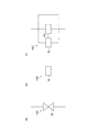
圧力抵抗調整部14は、圧力抵抗を高めることができる構造であればどのような構造を採用してもよく、例えば、図2に示すような構造を採用してよい。具体的には、図2(a)に示すように、電磁弁などの開閉弁19で構成される圧力抵抗調整部14Aを採用してよい。圧力抵抗調整部14Aは、開閉弁19の開度を変更することによって、圧力抵抗を変更可能である。すなわち、圧力抵抗調整部14Aは、圧力抵抗を高めるときは開閉弁19の開度を下げ、圧力抵抗を戻す場合は開閉弁19の開度を上げる。
The pressure
あるいは、図2(b),(c)に示すように、圧力抵抗を変更不可能な高圧力抵抗部材18を用いた圧力抵抗調整部14B,14Cを採用してもよい。圧力抵抗調整部14Bでは、ライン上に高圧力抵抗部材18が設けられており、製造時に圧力抵抗を調整されたら、当該圧力抵抗で固定される。圧力抵抗調整部14Cは、高圧力抵抗部材18が設けられる一以上のラインと、高圧力抵抗部材18が設けられないラインとを、並列に有している。並列に設けられた高圧力抵抗部材18は各々異なる圧力抵抗に設定されており、圧力抵抗調整部14Cでは、弁の切り替えなどによって、最適な圧力抵抗に設定できるように、高圧力抵抗部材18を選択することができる。あるいは、圧力抵抗調整部14Cでは、膜モジュール2で濾過を行っていないときは、高圧力抵抗部材18が設けられていないラインを選択してよい。
Alternatively, as shown in FIGS. 2B and 2C, pressure
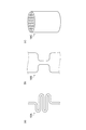
高圧力抵抗部材18は、ライン中の通常の配管に比して圧力抵抗を高められるものであればどのような構造を採用してもよく、例えば、図3に示すような部材を採用してよい。図3(a)に示す高圧力抵抗部材18Aは、配管を複数回屈曲させることによって圧力抵抗が高められている。あるいは、配管を螺旋状に巻くことによって圧力抵抗を高めてもよい。図3(b)に示す高圧力抵抗部材18Bは、配管径を局所的に細くすることによって圧力抵抗が高められている。図3(c)に示す高圧力抵抗部材18Cは、オリフィス構造となっており、配管中に一つもしくは複数の貫通孔を設けることによって圧力抵抗が高められている。
The high
制御部16は、水処理システム1全体の運転制御を行う。制御部16は、原水ポンプ4、流量計6、空気ブロワ7、圧力計8,9、濾過ポンプ12、逆洗ポンプ13、及び圧力抵抗調整部14と電気的に接続されている。ただし、圧力抵抗調整部14が圧力抵抗を変更不可能な場合は、電気的に接続されていなくともよい。制御部16は、膜モジュール2で濾過を行うときは、圧力計8,9の検出値に基づいて、原水ポンプ4、空気ブロワ7、濾過ポンプ12を制御すると共に、圧力抵抗調整部14で圧力抵抗を設定する。制御部16は、膜モジュールの逆洗を行うときは、逆洗ポンプ13を制御する。
The
次に、水処理システム1が原水の水処理を行うときの動作手順の一例について説明する。
Next, an example of an operation procedure when the
まず、制御部16は、原水ポンプ4及び空気ブロワ7を起動させる。原水ポンプ4は、原水槽3から原水を吸引すると共にラインL1を介して膜モジュール2へ原水を供給する。空気ブロワ7は、原水に空気を供給することで原水を気液混相流とする。このとき、原水循環速度は、低い速度に設定することができる。具体的には、原水ポンプ4は、少なくともチューブラー膜5における原水の流速が0.05m/s以上となるように原水を供給してよく、0.1m/s以上となるように原水を供給してよい。また、原水ポンプ4は、少なくともチューブラー膜5における原水の流速が0.25m/s以下となるように原水を供給してよく、0.3m/s以下、0.5m/s以下となるように原水を供給してよい。また、空気ブロワ7による気泡投入比率(ボイド率)を高くすることができ、0.1〜0.7程度、より好ましくは0.3〜0.5程度に設定することができる。また、制御部16は、濾過ポンプ12を起動させる。濾過ポンプ12のフラックスは、0.5〜3.0m/d程度に設定される。ただし、原水循環速度、気泡投入比率、フラックスは上述の数値範囲に限定されるものではなく、当該数値範囲より小さくともよく、大きくともよい。
First, the
制御部16は、膜モジュール2の入口側の圧力計8による検出値及び出口側の圧力計9の検出値を取得する。制御部16は、これらの検出結果に基づいて、圧力抵抗調整部14の圧力抵抗を設定する。すなわち、制御部16は、入口側の圧力と出口側の圧力の圧力差が所定の目標値に達していないときは、圧力抵抗調整部14の圧力抵抗を高める。あるいは、制御部16は、運転開始の時点で圧力抵抗調整部14を所定の圧力抵抗となるように設定しておき、運転中に圧力計8,9の検出値を監視しながら、圧力抵抗の微調整を行ってもよい。
The
膜モジュール2の各チューブラー膜5に均一に原水を流すことができるときの入口側及び出口側の好適な圧力は、水処理システム1のライン中の配管の径や屈曲具合や継手の数などによって異なるが、膜モジュール2の入口部2A付近の圧力は、第1実施形態においては、10〜20kPa程度であることが好ましく、出口部2B付近の圧力は、0〜10kPa程度であることが好ましい。ただし、これらの数値はシステムの各種条件によって変動するものであるため、当該数値範囲に限定されるものではない。なお、膜モジュール2の入口側と出口側の圧力差に基づいて圧力抵抗調整部14を制御することがより好ましいが、入口側の圧力、すなわち圧力計8の検出値のみに基づいて制御してもよい。
Suitable pressures on the inlet side and outlet side when raw water can flow uniformly through the
次に、本実施形態に係る水処理システム1の作用・効果について説明する。
Next, the operation and effect of the
まず、従来の水処理システムについて説明する。従来の水処理システムは、図1に示す水処理システム1から圧力抵抗調整部14を除いた構成を有する。
First, a conventional water treatment system will be described. The conventional water treatment system has a configuration in which the pressure
上述のように、膜モジュール2は、数十本から数百本の管状膜で構成されている。従来の水処理システムにおいて、そのような膜モジュール2に対して、原水に空気を混合した気液混相流を流す場合、図4(a)に示すように、膜モジュール2内の多数のチューブラー膜5に均一に原水と空気が流れず、中にはチューブラー膜5に空気が詰まることにより原水が全く流れないものも発生する。このように、原水が流れないチューブラー膜5が発生すると、実質的に濾過に寄与するチューブラー膜5の本数が減ることによって濾過効率が低下することに加え、吸引圧力によって付着した固体が乾燥することにより、チューブラー膜5の寿命が縮まるという問題が発生する。
As described above, the
このような問題は、膜洗浄効果の高い気泡投入比率を保ちながら、動力削減のために原水の流速を小さくした場合に発生し易い。従って、空気量を少なくすると共に所定速度以上の流速で運転することによって、流速の勢いで気泡が管状膜中に詰まらないようにする方法が考えられる。しかしながら、当該方法を採用したとしても、複数のチューブラー膜5に均一に流すことができない場合がある。また、当該方法では、空気量が少ないために膜洗浄効果を高めることが出来ず、高い動力が必要となるため、原水ポンプ4を大きくしなければならないという問題がある。
Such a problem is likely to occur when the flow rate of the raw water is reduced in order to reduce power while maintaining the bubble injection ratio with a high membrane cleaning effect. Therefore, it is conceivable to reduce the amount of air and operate at a flow rate equal to or higher than a predetermined speed so that bubbles are not clogged in the tubular membrane due to the momentum of the flow rate. However, even if this method is adopted, it may not be possible to flow uniformly through the plurality of
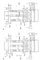
ここで、気液混相流の原水を複数のチューブラー膜5に均一に流すことができないことを確認するための試験について、図5を参照して説明する。図5(a)及び図5(b)に示すように、複数のチューブラー膜5は、入口5a側で上流側の接続部21に接続され、出口5b側で下流側の接続部22に接続されている。接続部21に流れ込んだ原水は、分岐されて各チューブラー膜5の入口5aから内部へ流れる。また、各チューブラー膜5の内部を流れた原水は、出口5bから排出されて接続部22で合流する。なお、図5に示す例では、チューブラー膜5は、入口5aが下側に配置され、出口5bが上側に配置されるように上下方向に延びている。
Here, a test for confirming that the raw water of the gas-liquid mixed phase flow cannot be uniformly fed to the plurality of
まず、第1の試験では、図5(a)に示すように、原水が流れていない状態のチューブラー膜5に対して、気液混相流の原水を供給した。このとき、チューブラー膜5での流速が0.1m/sとなるように原水を供給した。このとき、原水は各チューブラー膜5に均一な気液混相流として流れ、原水の水面は各チューブラー膜5の内部を上昇した。図5(b)に示すように、原水の水面がチューブラー膜5の出口5bに達すると、一部のチューブラー膜5(図ではチューブラー膜5B)において、エアリフト効果により気泡の急激な加速が発生した。また、一部のチューブラー膜5で気泡の急激な加速が発生することにより、圧力のバランスが崩れ、他のチューブラー膜5では上下振動や逆流が発生した。
First, in the first test, as shown in FIG. 5A, gas-liquid mixed phase raw water was supplied to the
また、第2の試験では、図5(a),(b)に示す膜モジュール2から、上流側の接続部22を除き、各チューブラー膜5の出口5bを開放させたものを準備した。このような膜モジュール2について、原水が流れていない状態のチューブラー膜5に対して、気液混相流の原水を供給した。このとき、原水は各チューブラー膜5に入り込み、原水の水面は各チューブラー膜5の内部を上昇した。第2の試験においても、エアリフト効果により一部のチューブラー膜5で気泡の急激な加速が発生することにより、圧力のバランスが崩れ、他のチューブラー膜5では上下振動や逆流が発生した。
In the second test, the
また、第3の試験では、図5(a),(b)に示す膜モジュール2を用いた。原水が流れていない状態のチューブラー膜5に対して、微小な流速またはほぼ流速0m/sにて気液混相流の原水を供給した。このとき、原水は各チューブラー膜5に均一な気液混相流として流れた。第3の試験においても、エアリフト効果により一部のチューブラー膜5で気泡の急激な加速が発生することにより、圧力のバランスが崩れ、他のチューブラー膜5では上下振動や逆流が発生した。
In the third test, the
また、第4の試験では、図5(a),(b)に示す膜モジュール2を用いた。少なくともチューブラー膜5での流速を0.1m/sにして原水を膜モジュール2に供給した。膜モジュール2に原水が満たされた状態で、空気ブロワ7で空気を供給した。気泡は各チューブラー膜5へ入りこんだ。しかしながら、第4の試験においても、気泡がチューブラー膜5の出口5bに達すると、エアリフト効果により一部のチューブラー膜5で気泡の急激な加速が発生することにより、圧力のバランスが崩れ、他のチューブラー膜5では上下振動や逆流が発生した。
In the fourth test, the
また、第5の試験では、図5(a),(b)に示す膜モジュール2を用いた。少なくともチューブラー膜5での流速を0.5m/sにして十分な流速で原水を膜モジュール2に供給した。膜モジュール2に原水が満たされた状態で、空気ブロワ7で空気を供給した。気泡は各チューブラー膜5へ入りこみ、気泡がチューブラー膜5の出口5bに達しても、一部のチューブラー膜5で上下振動や逆流が発生することなく、各チューブラー膜5に気液混相流が均一に流れた。
In the fifth test, the
なお、上述の試験では、マノメータを用いて各チューブラー膜5での圧力を観察した。例えば、図5(a)及び図5(b)に示すように、複数のチューブラー膜5のうち一部のチューブラー膜5Aの入口5a側にマノメータML1を取り付けると共に、出口5b側にマノメータML2を取り付けた。マノメータML1,ML2の水面高さは、当該マノメータML1,ML2が取り付けられた位置での圧力を示している。例えば、気液混相流がチューブラー膜5Aの出口5bに達してエアリフトが発生して圧力のバランスが崩れると、チューブラー膜5BのマノメータML1,ML2の水面が上下に大きく振動する。
In the above test, the pressure at each
以上の試験より、各チューブラー膜5の圧力にばらつきが生じていることが理解された。これらのばらつきは、各チューブラー膜5の製品規格(厚さ、長さ、たわみなど)の誤差によるものではなく、気泡が各チューブラー膜5にランダムに入り込むことによって生じる各チューブラー膜5の圧力変動のばらつきと考えられ得る。
From the above test, it was understood that the pressure of each
ここで、本発明者らは、鋭意研究の結果、次の知見を見出すに至った。すなわち、本発明者らは、原水が通過するライン上の圧力抵抗を適切に高めることによって、膜モジュール2の複数のチューブラー膜に均一に気液混相流の原水を流すことができることを見出した。また、本発明者らは、当該方法によって、原水の循環速度を高くすることなく、且つ、空気量を少なくすることなく、複数のチューブラー膜5に原水を均一に流すことができることを見出した。すなわち、各チューブラー膜5での圧力変動のばらつきを無視できる程度にまで圧力抵抗を高めることで、圧力変動のばらつきに起因する不安定な原水の流れを抑制し、気液混相流の原水を各チューブラー膜5に対して均一に流すことが出来る点を見出した。
Here, as a result of intensive studies, the present inventors have found the following knowledge. That is, the present inventors have found that by appropriately increasing the pressure resistance on the line through which the raw water passes, the raw water of the gas-liquid mixed phase flow can be made to flow uniformly to the plurality of tubular membranes of the
そこで、本実施形態に係る水処理システム1は、少なくとも膜モジュール2で濾過を行っているときに、原水に対する圧力抵抗が高められる圧力抵抗調整部14を備えている。複数のチューブラー膜5の内部を気液混相流の原水が流れる時にチューブラー膜5間で圧力変動のばらつきが生じるとしても、当該圧力変動のばらつきの影響を無視できるように圧力抵抗調整部14で圧力抵抗を高めることによって、圧力変動のばらつきに起因する不安定な原水の流れを抑制することができる。例えば、圧力抵抗調整部14で圧力抵抗が高められていることで、膜モジュール2内にある個々のチューブラー膜5の圧力変動のばらつきが無視され、エアリフトの発生が抑えられ、気泡が膜モジュール2内を均一に流れる。従って、膜モジュール2が多数のチューブラー膜5を有している場合であっても、気液混相流の原水は各チューブラー膜5を均一に流れることができる。更に、膜洗浄効率を高くするために空気量を多くし、且つ、動力削減のために流速を小さくした場合(例えば、少なくとも膜モジュールにおける原水の流速が0.05〜0.25m/s)であっても、気液混相流の原水は、各チューブラー膜5を均一に流れることができる。以上によって、水処理システム1は、高い膜洗浄効率を保ちつつ、低い動力にて、複数のチューブラー膜5に均一に気液混相流の原水を流すことができる。
Therefore, the
また、本実施形態に係る水処理システムに1おいて、少なくとも、膜モジュール2の入口側及び出口側の圧力を検出する圧力計8,9と、原水ポンプ4、空気ブロワ7、及び圧力抵抗調整部14を制御する制御部16と、を備えている。また、圧力抵抗調整部14は、弁の開閉によって圧力抵抗を変更可能であり、制御部16は、圧力計8,9の検出値に基づいて、原水ポンプ4及び空気ブロワ7を制御すると共に、圧力抵抗調整部14で圧力抵抗を設定してよい。これによって、制御部16は、圧力計8,9の検出値を取得することで、膜モジュール2の入口側の圧力に基づいて、圧力抵抗調整部14の圧力抵抗を設定することができる。従って、制御部16は、気液混相流の原水が複数の管状膜を均一に流れ易い条件となるように、圧力抵抗を設定することが可能となる。
Further, in the
[第2実施形態]
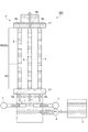
図6を参照して、第2実施形態に係る水処理システム100について説明する。第2実施形態に係る水処理システム100は、圧力抵抗調整部50が複数のチューブラー膜5のそれぞれに対して設けられる点で、第1実施形態に係る水処理システム1と主に相違する。圧力抵抗調整部50は、少なくともチューブラー膜5の入口5aから、ラインL2の下流側の端部(原水が大気開放される位置)までの合計の圧力損失を大きくする。第1実施形態に係る水処理システム1では、各チューブラー膜5へ分岐した原水が再び合流するラインL2での圧力損失を大きくするものあったが、第2実施形態に係る水処理システム100の圧力抵抗調整部50は、複数のチューブラー膜5の一つ一つでの圧力損失を大きくしている。なお、水処理システム100は、第1実施形態の圧力抵抗調整部14がラインL2に設けられておらず、チューブラー膜5に圧力抵抗調整部50が設けられている点以外は、図1に示す第1実施形態の水処理システム1と同様な構成を有している。[Second Embodiment]
With reference to FIG. 6, the
図6に示すように、複数のチューブラー膜5は、入口5a側で上流側の接続部21に接続され、出口5b側で下流側の接続部22に接続されている。接続部21に流れ込んだ原水は、分岐されて各チューブラー膜5の入口5aから内部へ流れる。また、各チューブラー膜5の内部を流れた原水は、出口5bから排出されて接続部22で合流する。このような膜モジュール2の各チューブラー膜5に対して、圧力抵抗調整部50としてオリフィス51が設けられる。オリフィス51は、チューブラー膜5の下流側の端部、すなわち出口5bに設けられている。ただし、オリフィス51は、1本当たりのチューブラー膜5の合計の圧力損失を大きくすることができればどの位置に設けられていてもよく、出口5bと入口5aとの間の領域のいずれの位置に設けられてもよい。また、一本当たりのチューブラー膜5に対して設けられるオリフィス51の数も限定されず、複数設けてもよい。なお、原水ポンプ4がラインL1に設けられる場合は、圧力抵抗調整部50は原水ポンプ4の下流側に設けられることとなり、原水ポンプ4がラインL2に設けられる場合は、圧力抵抗調整部50は原水ポンプ4の上流側に設けられることとなる。
As shown in FIG. 6, the plurality of
オリフィス51は、チューブラー膜5の内径よりも小さい内径を有しており、このように部分的に内径を小さくすることによって圧力損失を大きくする。チューブラー膜5での圧力損失は、本研究条件では、流速0.1m/sのときに約20mmAqである。ただし、このような数値に限定されるものではない。
The
圧力抵抗調整部50は、膜モジュール2のチューブラー膜5での圧力損失が100mmAq以上となるように設定されてよい。このような数値範囲とすることによって、気液混相流の原水を各チューブラー膜5に均一に流すことができる。ただし、このような数値に限定されるものではない。また、膜モジュール2のチューブラー膜5での圧力損失の上限値は、使用する装置の条件によって変化するものであるが、例えば4000mmAq以下となるように圧力抵抗調整部50が設定されてよい。ただし、このような数値に限定されるものではない。このような数値範囲とすることによって、原水ポンプ4の動力を必要以上に高めることなく所望の流速で原水を供給することができる。
The pressure
オリフィス51のように内径を小さくすることによる圧力損失(Δh)は、例えば、以下の式(1)及び式(2)から導き出される式(3)によって演算することができる。なお、式において、v0はオリフィス51での原水の流速、d0はオリフィス51の内径、vはチューブラー膜5での原水の流速、dはチューブラー膜5の内径である。
Δh=ζ0・v0 2/2g=ζ・v2/2g …(1)
ζ=ζ0(d/d0)4 …(2)
Δh=ζ0・(d/d0)4・v2/2g …(3)
The pressure loss (Δh) by reducing the inner diameter like the
Δh = ζ 0 · v 0 2 / 2g = ζ · v 2 / 2g (1)
ζ = ζ 0 (d / d 0 ) 4 (2)
Δh = ζ 0 · (d / d 0 ) 4 · v 2 / 2g (3)
以上のように、本実施形態に係る水処理システム100は、膜モジュール2において原水に対する圧力抵抗が高められる圧力抵抗調整部50を備えている。複数のチューブラー膜5の内部を気液混相流の原水が流れる時にチューブラー膜5間で圧力変動のばらつきが生じるとしても、当該圧力変動のばらつきの影響を無視できるように圧力抵抗調整部50で圧力抵抗を高めることによって、圧力変動のばらつきに起因する不安定な原水の流れを抑制することができる。具体的には、圧力抵抗調整部50が、膜モジュール2での圧力損失が100mmAq以上となるように設定されることによって、圧力変動のばらつきに起因する不安定な原水の流れを抑制することができる。従って、膜モジュール2が多数のチューブラー膜5を有している場合であっても、気液混相流の原水は各チューブラー膜5を均一に流れることができる。更に、膜洗浄効率を高くするために空気量を多くし、且つ、動力削減のために流速を小さくした場合(例えば、少なくとも膜モジュール2における原水の流速が0.05〜0.25m/s)であっても、気液混相流の原水は、各チューブラー膜5を均一に流れることができる。以上によって、水処理システム1は、高い膜洗浄効率を保ちつつ、低い動力にて、複数のチューブラー膜5に均一に気液混相流の原水を流すことができる。
As described above, the
また、圧力抵抗調整部50は、膜モジュール2の複数のチューブラー膜5のそれぞれに対して設けられている。これによって、気液混相流の原水は、より確実に各チューブラー膜5を均一に流れることができる。
In addition, the pressure
なお、内径を小さくすることによって圧力損失を大きくするための圧力抵抗調整部50としてオリフィス51を例示した。しかし、圧力抵抗調整部50は、オリフィス51に限定されず、図7に示す水処理システム200のように、チューブラー膜5自体の内径を部分的に小さくした小径部54であってもよい。小径部54の内径は、チューブラー膜5の基本部53(図6の形態でのチューブラー膜5に相当する圧力損失を有する部分であり、小径部54と区別するために便宜的に「基本部」と称する)の内径よりも小さい。図7では、小径部54はチューブラー膜5の出口5bに設けられている。ただし、小径部54は、1本当たりのチューブラー膜5の合計の圧力損失を大きくすることができればどの位置に設けられていてもよく、出口5bと入口5aとの間の領域のいずれの位置に設けられてもよい。また、一本当たりのチューブラー膜5に対して設けられる小径部54の数も限定されず、複数設けてもよい。また、小径部54の長さは特に限定されない。例えば、チューブラー膜5全体を小径部54としてもよい。また、オリフィス51と小径部54を組み合わせてもよい。
In addition, the
[第3実施形態]
図8を参照して、第3実施形態に係る水処理システム300について説明する。第3実施形態に係る水処理システム300は、圧力抵抗調整部50としてチューブラー膜5を長くした延長部56を採用した点で、第2実施形態に係る水処理システム100と相違する。延長部56は、基本部53のみによって構成されるチューブラー膜に比して、チューブラー膜5全体を長くすることによって設けられる。なお、基本部53とは、図6の形態でのチューブラー膜5に相当する長さ(圧力損失)を有する部分である。基本部53での圧力損失は、本研究条件では、流速0.1m/sのときに約20mmAqである。延長部56は、摩擦によって圧力損失を大きくするものである。本実施形態の圧力抵抗調整部50の圧力損失の数値範囲は、第2実施形態に係る圧力抵抗調整部50による圧力損失の数値範囲と同様である。[Third Embodiment]
With reference to FIG. 8, the
具体的に、延長部56を有するチューブラー膜5のように摩擦によって得られる圧力損失(Δh)は、以下の式(4)によって演算することができる。なお、式において、fはチューブラー膜5の摩擦係数であり、lはチューブラー膜5の長さである。
Δh=f・(l/d)・v2/2g …(4)
Specifically, the pressure loss (Δh) obtained by friction as in the
Δh = f · (l / d) · v 2 / 2g (4)
本発明は、上述の実施形態に限定されるものではない。例えば、図1は水処理システムのシステム構成の一例に過ぎず、異なるシステム構成を採用してもよい。また、圧力抵抗調整部14の圧力抵抗は、圧力計8,9の検出値に基づいて設定しなくともよく、運転開始時に所定の圧力抵抗に設定した後に濾過を開始してもよい。
The present invention is not limited to the embodiment described above. For example, FIG. 1 is only an example of the system configuration of the water treatment system, and a different system configuration may be adopted. Further, the pressure resistance of the pressure
また、圧力抵抗調整部は、第2実施形態で例示したように径を小さくすることで圧力損失を大きくする方法と、第3実施形態で例示したように摩擦によって圧力抵抗を大きくする方法とを組み合わせてもよい。 In addition, the pressure resistance adjusting unit includes a method of increasing the pressure loss by reducing the diameter as exemplified in the second embodiment, and a method of increasing the pressure resistance by friction as exemplified in the third embodiment. You may combine.
[実施例]
以下、実施例により本発明を詳細に説明するが、本発明はこれらの実施例に限定されるものではない。[Example]
EXAMPLES Hereinafter, although an Example demonstrates this invention in detail, this invention is not limited to these Examples.
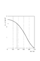
まず、圧力損失の演算の具体的な例について説明する。まず、チューブラー膜の内径(d)を4mmとし、チューブラー膜の長さを1mとし、圧力抵抗調整部として絞り比(d0/d)を0.35としたオリフィスを用いる。この場合、図9のグラフを用いてζ0=2.3という値が得られる。これらの値を式(3)へ代入することで、圧力抵抗調整部の圧力損失が、Δh=78mmAq(約80mmAq)と算出される。First, a specific example of calculation of pressure loss will be described. First, an orifice in which the inner diameter (d) of the tubular membrane is 4 mm, the length of the tubular membrane is 1 m, and the restriction ratio (d 0 / d) is 0.35 is used as the pressure resistance adjusting unit. In this case, a value of ζ 0 = 2.3 is obtained using the graph of FIG. By substituting these values into Equation (3), the pressure loss of the pressure resistance adjusting unit is calculated as Δh = 78 mmAq (about 80 mmAq).
次に、摩擦による圧力損失が上述のオリフィスの78mmAq(約80mmAq)に等しくなるような延長部の長さを算出する。本研究での運転条件においては、式(4)に対して、摩擦係数f=(Re/84=)0.16、チューブラー膜5の内径d=4mm、圧力損失Δh=78×10−3mAq(78mmAq)を代入することで、l≒3.8(約4m)という値が得られる。すなわち、約4mの延長部によって約80mmAqの圧力損失を得られるため、チューブラー膜は1m当り約20mmAqの圧力損失に対応する。このとき、チューブラー膜のうち基本部に対応する部分の長さは1mであるため、基本部での圧力損失は約20mmAqとなる。従って、オリフィスを設けた1mのチューブラー膜と、1mの基本部に4mの延長部を設けたチューブラー膜(合計5mのチューブラー膜)は、いずれも圧力損失が100mmAqとなる。以下の実施例及び比較例では、それぞれ延長部の条件またはオリフィスの条件が異なっているが、式(3)または式(4)を用いることで圧力損失を算出することができる。Next, the length of the extension is calculated so that the pressure loss due to friction becomes equal to 78 mmAq (about 80 mmAq) of the orifice. Under the operating conditions in this study, the friction coefficient f = (Re / 84 =) 0.16, the inner diameter d = 4 mm of the
[実施例1]
基本部の内径(d)を4mmとし、基本部の長さを1mとし、摩擦係数(f)を0.16とし、延長部の長さを4m(内径は4mm)とし、出口に内径が4mm(すなわち絞り比=1)のオリフィスを設けたチューブラー膜を準備した。このときの、摩擦による圧力損失(延長部と基本部の合計の圧力損失)は100mmAqであり、オリフィスによる圧力損失は0mmAqであった。従って、チューブラー膜の合計の圧力損失、すなわち基本部及び圧力抵抗調整部の合計の圧力損失は100mmAqであった。また、膜モジュールのチューブラー膜の本数を29とした。また、空気を約0.065m/sで供給してスラグ流とし、チューブラー膜での流速が0.1m/sとなるように設定した。このような条件下で運転を行った結果、29本のチューブラー膜のうち、28本のチューブラー膜にスラグ流が流れていることを確認した。全体のチューブラー膜の本数に対する、スラグ流が流れているチューブラー膜の本数の割合を「スラグ流分散率」として算出し、図10に示すグラフにプロットした。なお、このときのスラグ流分散率は96.6%と算出された。[Example 1]
The inner diameter (d) of the basic part is 4 mm, the length of the basic part is 1 m, the friction coefficient (f) is 0.16, the length of the extension part is 4 m (inner diameter is 4 mm), and the inner diameter is 4 mm at the outlet. A tubular membrane provided with an orifice having a squeezing ratio of 1 was prepared. At this time, the pressure loss due to friction (total pressure loss of the extension portion and the basic portion) was 100 mmAq, and the pressure loss due to the orifice was 0 mmAq. Therefore, the total pressure loss of the tubular membrane, that is, the total pressure loss of the basic portion and the pressure resistance adjusting portion was 100 mmAq. The number of tubular membranes in the membrane module was 29. In addition, air was supplied at about 0.065 m / s to form a slag flow, and the flow rate at the tubular membrane was set to 0.1 m / s. As a result of operating under such conditions, it was confirmed that slag flow was flowing in 28 tubular membranes out of 29 tubular membranes. The ratio of the number of tubular membranes in which the slag flow is flowing to the total number of tubular membranes was calculated as “slag flow dispersion ratio” and plotted in the graph shown in FIG. In addition, the slag flow dispersion rate at this time was calculated as 96.6%.
[実施例2]
基本部の内径(d)を4mmとし、基本部の長さを1mとし、摩擦係数(f)を0.16とし、延長部の長さを0mとし、出口に内径が1mm(すなわち絞り比=0.25)のオリフィスを設けたチューブラー膜を準備した。このときの、摩擦による圧力損失(基本部の圧力損失)は20mmAqとなり、オリフィスによる圧力損失は327mmAqとなった。従って、チューブラー膜の合計の圧力損失、すなわち基本部及び圧力抵抗調整部の合計の圧力損失は347mmAqであった。また、膜モジュールのチューブラー膜の本数を30とし、当該膜モジュールを4個準備した。空気を約0.065m/sで供給してスラグ流とし、チューブラー膜での流速が0.1m/sとなるように設定した。4個の膜モジュールについての結果を図10に示すグラフ上にプロットして示す。[Example 2]
The inner diameter (d) of the basic part is 4 mm, the length of the basic part is 1 m, the friction coefficient (f) is 0.16, the length of the extension part is 0 m, and the inner diameter is 1 mm at the outlet (that is, the drawing ratio = A tubular membrane provided with an orifice of 0.25) was prepared. At this time, the pressure loss due to friction (pressure loss at the basic portion) was 20 mmAq, and the pressure loss due to the orifice was 327 mmAq. Therefore, the total pressure loss of the tubular membrane, that is, the total pressure loss of the basic portion and the pressure resistance adjusting portion was 347 mmAq. Further, the number of tubular membranes in the membrane module was set to 30, and four membrane modules were prepared. Air was supplied at about 0.065 m / s to form a slag flow, and the flow rate at the tubular membrane was set to 0.1 m / s. The results for the four membrane modules are plotted on the graph shown in FIG.
[実施例3]
基本部の長さを0.6mとした点以外、実施例2と同様の条件とした。このときの、摩擦による圧力損失(基本部の圧力損失)は12mmAqとなり、オリフィスによる圧力損失は327mmAqとなった。従って、チューブラー膜の合計の圧力損失、すなわち基本部及び圧力抵抗調整部の合計の圧力損失は339mmAqであった。このような4個の膜モジュールについての結果を図10に示すグラフ上にプロットして示す。[Example 3]
The conditions were the same as in Example 2 except that the length of the basic part was 0.6 m. At this time, the pressure loss due to friction (pressure loss at the basic portion) was 12 mmAq, and the pressure loss due to the orifice was 327 mmAq. Therefore, the total pressure loss of the tubular membrane, that is, the total pressure loss of the basic portion and the pressure resistance adjusting portion was 339 mmAq. The results for such four membrane modules are plotted on the graph shown in FIG.
[実施例4]
基本部の内径を8mmとし、オリフィスの内径を2mm(すなわち絞り比=0.25)とした点以外、実施例2と同様の条件とした。このときの、摩擦による圧力損失(基本部の圧力損失)は10mmAqとなり、オリフィスによる圧力損失は327mmAqとなった。従って、チューブラー膜の合計の圧力損失、すなわち基本部及び圧力抵抗調整部の合計の圧力損失は337mmAqであった。このような4個の膜モジュールについての結果を図10に示すグラフ上にプロットして示す。[Example 4]
The conditions were the same as in Example 2 except that the inner diameter of the basic part was 8 mm and the inner diameter of the orifice was 2 mm (ie, the reduction ratio = 0.25). At this time, the pressure loss due to friction (pressure loss in the basic portion) was 10 mmAq, and the pressure loss due to the orifice was 327 mmAq. Therefore, the total pressure loss of the tubular membrane, that is, the total pressure loss of the basic portion and the pressure resistance adjusting portion was 337 mmAq. The results for such four membrane modules are plotted on the graph shown in FIG.
[実施例5]
オリフィスの内径を2mm(すなわち絞り比=0.5)とした点以外、実施例2と同様の条件とした。このときの、摩擦による圧力損失(基本部の圧力損失)は20mmAqとなり、オリフィスによる圧力損失は15mmAqとなった。従って、チューブラー膜の合計の圧力損失、すなわち基本部及び圧力抵抗調整部の合計の圧力損失は35mmAqであった。このような4個の膜モジュールについての結果を図10に示すグラフ上にプロットして示す。[Example 5]
The conditions were the same as in Example 2, except that the inner diameter of the orifice was 2 mm (ie, the restriction ratio = 0.5). At this time, the pressure loss due to friction (pressure loss in the basic portion) was 20 mmAq, and the pressure loss due to the orifice was 15 mmAq. Therefore, the total pressure loss of the tubular membrane, that is, the total pressure loss of the basic portion and the pressure resistance adjusting portion was 35 mmAq. The results for such four membrane modules are plotted on the graph shown in FIG.
[実施例6]
基本部の長さを0.6mとし、オリフィスの内径を2mm(すなわち絞り比=0.5)とした点以外、実施例2と同様の条件とした。このときの、摩擦による圧力損失(基本部の圧力損失)は12mmAqとなり、オリフィスによる圧力損失は15mmAqとなった。従って、チューブラー膜の合計の圧力損失、すなわち基本部及び圧力抵抗調整部の合計の圧力損失は27mmAqであった。このような4個の膜モジュールについての結果を図10に示すグラフ上にプロットして示す。[Example 6]
The conditions were the same as in Example 2 except that the length of the basic portion was 0.6 m and the inner diameter of the orifice was 2 mm (ie, the drawing ratio = 0.5). At this time, the pressure loss due to friction (pressure loss in the basic portion) was 12 mmAq, and the pressure loss due to the orifice was 15 mmAq. Therefore, the total pressure loss of the tubular membrane, that is, the total pressure loss of the basic portion and the pressure resistance adjusting portion was 27 mmAq. The results for such four membrane modules are plotted on the graph shown in FIG.
[実施例7]
基本部の内径を8mmとし、オリフィスの内径を4mm(すなわち絞り比=0.5)とした点以外、実施例2と同様の条件とした。このときの、摩擦による圧力損失(延長部と基本部の合計の圧力損失)は10mmAqとなり、オリフィスによる圧力損失は15mmAqとなった。従って、チューブラー膜の合計の圧力損失、すなわち基本部及び圧力抵抗調整部の合計の圧力損失は25mmAqであった。このような4個の膜モジュールについての結果を図10に示すグラフ上にプロットして示す。[Example 7]
The conditions were the same as in Example 2, except that the inner diameter of the basic portion was 8 mm and the inner diameter of the orifice was 4 mm (that is, the aperture ratio = 0.5). At this time, the pressure loss due to friction (the total pressure loss of the extension portion and the basic portion) was 10 mmAq, and the pressure loss due to the orifice was 15 mmAq. Therefore, the total pressure loss of the tubular membrane, that is, the total pressure loss of the basic portion and the pressure resistance adjusting portion was 25 mmAq. The results for such four membrane modules are plotted on the graph shown in FIG.
[比較例]
オリフィスの内径を4mm、すなわち絞り比=1であり実質的に圧力抵抗の調整を行っていない構成とした点以外、実施例2と同様の条件とした。このときの、摩擦による圧力損失(基本部の圧力損失)は20mmAqとなり、オリフィスによる圧力損失は0mmAqとなった。従って、チューブラー膜の合計の圧力損失、すなわち基本部の圧力損失は20mmAqであった。このような4個の膜モジュールについての結果を図10に示すグラフ上にプロットして示す。[Comparative example]
The conditions were the same as in Example 2, except that the inner diameter of the orifice was 4 mm, that is, the restriction ratio = 1 and the pressure resistance was not substantially adjusted. At this time, the pressure loss due to friction (pressure loss at the basic portion) was 20 mmAq, and the pressure loss due to the orifice was 0 mmAq. Therefore, the total pressure loss of the tubular membrane, that is, the pressure loss of the basic part was 20 mmAq. The results for such four membrane modules are plotted on the graph shown in FIG.
(評価)
図10のグラフに示すように、比較例に比して、チューブラー膜において圧力抵抗調整部で圧力損失を大きくした各実施例の方が、スラグ流分散率が高い。従って、実施例では、比較例に比してスラグ流を各チューブラー膜に均一に流すことができる点が理解される。また、実施例1〜実施例4の結果より、チューブラー膜での圧力損失が100mmAq以上となるように圧力抵抗調整部を設定した場合、スラグ流分散率を90%以上とすることができ、スラグ流を各チューブラー膜に均一に流すことができる点が理解される。(Evaluation)
As shown in the graph of FIG. 10, the slag flow dispersion ratio is higher in each of the examples in which the pressure loss is increased by the pressure resistance adjusting unit in the tubular membrane as compared with the comparative example. Therefore, in an Example, it is understood that a slag flow can be made to flow uniformly to each tubular membrane compared with a comparative example. Moreover, from the results of Examples 1 to 4, when the pressure resistance adjustment unit is set so that the pressure loss in the tubular membrane is 100 mmAq or more, the slag flow dispersion ratio can be 90% or more, It is understood that a slag flow can be made to flow uniformly through each tubular membrane.
本発明は、複数の管状膜を有する膜モジュールを用いた水処理システムに利用可能である。 The present invention can be used in a water treatment system using a membrane module having a plurality of tubular membranes.
1,100,200,300…水処理システム、2…膜モジュール、4…原水ポンプ(原水供給部)、5…チューブラー膜(管状膜)、7…空気ブロワ(空気供給部)、8,9…圧力計(圧力検出部)、14,50…圧力抵抗調整部、16…制御部。 DESCRIPTION OF SYMBOLS 1,100,200,300 ... Water treatment system, 2 ... Membrane module, 4 ... Raw water pump (raw water supply part), 5 ... Tubular membrane (tubular membrane), 7 ... Air blower (air supply part), 8, 9 ... pressure gauge (pressure detection unit), 14, 50 ... pressure resistance adjustment unit, 16 ... control unit.
Claims (5)
前記原水の水源から前記膜モジュールへ前記原水を供給する原水供給部と、
前記原水に気体を供給し、前記膜モジュールに供給される前記原水を気液混相流とする気体供給部と、
少なくとも前記膜モジュールで濾過を行っているときに、前記原水に対する圧力抵抗が高められる圧力抵抗調整部と、
少なくとも、前記膜モジュールの入口側の圧力を検出する圧力検出部と、
前記原水供給部、前記気体供給部、及び前記圧力抵抗調整部を制御する制御部と、を備え、
前記圧力抵抗調整部は、前記原水供給部の下流側、又は前記原水供給部の上流側に設けられ、
前記圧力抵抗調整部は、弁の開度の変更によって前記圧力抵抗を変更可能であり、
前記制御部は、前記圧力検出部の検出値に基づいて、前記原水供給部及び前記気体供給部を制御すると共に、前記圧力抵抗調整部で前記圧力抵抗を設定する、水処理システム。 A membrane module that has a plurality of tubular membranes and flows raw water through the tubular membrane to filter the raw water;
A raw water supply unit for supplying the raw water from the raw water source to the membrane module;
A gas supply unit configured to supply a gas to the raw water and use the raw water supplied to the membrane module as a gas-liquid mixed phase flow;
A pressure resistance adjusting unit capable of increasing the pressure resistance with respect to the raw water when filtering at least with the membrane module;
At least a pressure detector for detecting the pressure on the inlet side of the membrane module;
A control unit for controlling the raw water supply unit, the gas supply unit, and the pressure resistance adjustment unit,
The pressure resistance adjustment unit is provided on the downstream side of the raw water supply unit or on the upstream side of the raw water supply unit,
The pressure resistance adjustment unit can change the pressure resistance by changing the opening of a valve,
The said control part is a water treatment system which sets the said pressure resistance with the said pressure resistance adjustment part while controlling the said raw | natural water supply part and the said gas supply part based on the detected value of the said pressure detection part.
前記原水の水源から前記膜モジュールへ前記原水を供給する原水供給部と、
前記原水に気体を供給し、前記膜モジュールに供給される前記原水を気液混相流とする気体供給部と、
少なくとも前記膜モジュールで濾過を行っているときに、前記原水に対する圧力抵抗が高められる圧力抵抗調整部と、
前記水源と前記膜モジュールを接続し、前記原水を流通させるラインと、を備え、
前記圧力抵抗調整部は、前記ライン上に設けられ、
前記圧力抵抗調整部は、前記ラインの構成部材に比して前記圧力抵抗が高い高圧力抵抗部材を有する、水処理システム。 A membrane module that has a plurality of tubular membranes and flows raw water through the tubular membrane to filter the raw water;
A raw water supply unit for supplying the raw water from the raw water source to the membrane module;
A gas supply unit configured to supply a gas to the raw water and use the raw water supplied to the membrane module as a gas-liquid mixed phase flow;
A pressure resistance adjusting unit capable of increasing the pressure resistance with respect to the raw water when filtering at least with the membrane module;
A line for connecting the water source and the membrane module and circulating the raw water,
The pressure resistance adjusting unit is provided on the line,
The said pressure resistance adjustment part is a water treatment system which has a high pressure resistance member whose said pressure resistance is high compared with the structural member of the said line.
前記原水の水源から前記膜モジュールへ前記原水を供給する原水供給部と、
前記原水に気体を供給し、前記膜モジュールに供給される前記原水を気液混相流とする気体供給部と、
少なくとも前記膜モジュールで濾過を行っているときに、前記原水に対する圧力抵抗が高められる圧力抵抗調整部と、を備え、
前記圧力抵抗調整部は、前記膜モジュールの複数の前記管状膜のそれぞれに対して設けられ、
前記圧力抵抗調整部は、前記管状膜の内径よりも小さい内径を有する、水処理システム。 A membrane module that has a plurality of tubular membranes and flows raw water through the tubular membrane to filter the raw water;
A raw water supply unit for supplying the raw water from the raw water source to the membrane module;
A gas supply unit configured to supply a gas to the raw water and use the raw water supplied to the membrane module as a gas-liquid mixed phase flow;
A pressure resistance adjusting unit capable of increasing the pressure resistance against the raw water when filtering at least with the membrane module;
The pressure resistance adjusting portion is provided for each of the plurality of tubular membranes of the membrane module,
The pressure resistance adjusting unit is a water treatment system having an inner diameter smaller than an inner diameter of the tubular membrane.
前記原水の水源から前記膜モジュールへ前記原水を供給する原水供給部と、
前記原水に気体を供給し、前記膜モジュールに供給される前記原水を気液混相流とする気体供給部と、
少なくとも前記膜モジュールで濾過を行っているときに、前記原水に対する圧力抵抗が高められる圧力抵抗調整部と、を備え、
前記圧力抵抗調整部は、前記原水供給部の下流側、又は前記原水供給部の上流側に設けられ、
前記原水供給部は、少なくとも前記膜モジュールにおける前記原水の流速が0.05〜0.25m/sとなるように、前記原水を供給し、
前記圧力抵抗調整部は、前記膜モジュールの前記管状膜での圧力損失が100mmAq以上となるように設定される、水処理システム。 A membrane module that has a plurality of tubular membranes and flows raw water through the tubular membrane to filter the raw water;
A raw water supply unit for supplying the raw water from the raw water source to the membrane module;
A gas supply unit configured to supply a gas to the raw water and use the raw water supplied to the membrane module as a gas-liquid mixed phase flow;
A pressure resistance adjusting unit capable of increasing the pressure resistance against the raw water when filtering at least with the membrane module;
The pressure resistance adjustment unit is provided on the downstream side of the raw water supply unit or on the upstream side of the raw water supply unit,
The raw water supply unit supplies the raw water so that at least a flow rate of the raw water in the membrane module is 0.05 to 0.25 m / s,
The said pressure resistance adjustment part is a water treatment system set so that the pressure loss in the said tubular membrane of the said membrane module may be 100 mmAq or more.
Applications Claiming Priority (3)
| Application Number | Priority Date | Filing Date | Title |
|---|---|---|---|
| JP2012288093 | 2012-12-28 | ||
| JP2012288093 | 2012-12-28 | ||
| PCT/JP2013/081195 WO2014103565A1 (en) | 2012-12-28 | 2013-11-19 | Water treatment system |
Publications (2)
| Publication Number | Publication Date |
|---|---|
| JPWO2014103565A1 JPWO2014103565A1 (en) | 2017-01-12 |
| JP6084635B2 true JP6084635B2 (en) | 2017-02-22 |
Family
ID=51020659
Family Applications (1)
| Application Number | Title | Priority Date | Filing Date |
|---|---|---|---|
| JP2014554240A Active JP6084635B2 (en) | 2012-12-28 | 2013-11-19 | Water treatment system |
Country Status (2)
| Country | Link |
|---|---|
| JP (1) | JP6084635B2 (en) |
| WO (1) | WO2014103565A1 (en) |
Families Citing this family (3)
| Publication number | Priority date | Publication date | Assignee | Title |
|---|---|---|---|---|
| HK1218151A1 (en) | 2013-01-25 | 2017-02-03 | Bio-Rad Laboratories, Inc. | System and method for performing droplet inflation |
| HUE059189T2 (en) | 2014-10-22 | 2022-10-28 | Koch Separation Solutions Inc | Membrane module system with bundle enclosures and pulsed aeration |
| USD779632S1 (en) | 2015-08-10 | 2017-02-21 | Koch Membrane Systems, Inc. | Bundle body |
Family Cites Families (4)
| Publication number | Priority date | Publication date | Assignee | Title |
|---|---|---|---|---|
| JP3562066B2 (en) * | 1995-10-05 | 2004-09-08 | 栗田工業株式会社 | Membrane separation device with hollow tubular membrane |
| JPH11309349A (en) * | 1998-04-28 | 1999-11-09 | Asahi Chem Ind Co Ltd | Washing of piping of filter membrane module |
| JP5230071B2 (en) * | 2006-03-17 | 2013-07-10 | メタウォーター株式会社 | Water treatment method and water treatment apparatus by membrane filtration |
| JP5269749B2 (en) * | 2009-11-13 | 2013-08-21 | セントラルフィルター工業株式会社 | Filtration device cleaning method |
-
2013
- 2013-11-19 JP JP2014554240A patent/JP6084635B2/en active Active
- 2013-11-19 WO PCT/JP2013/081195 patent/WO2014103565A1/en not_active Ceased
Also Published As
| Publication number | Publication date |
|---|---|
| WO2014103565A1 (en) | 2014-07-03 |
| JPWO2014103565A1 (en) | 2017-01-12 |
Similar Documents
| Publication | Publication Date | Title |
|---|---|---|
| US8658031B2 (en) | Method and apparatus for treating liquid containing impurities | |
| KR102115106B1 (en) | Hollow fiber membrane module and cleaning method | |
| JP2018108585A (en) | Air diffuser, air diffuser, and water treatment device | |
| US20120125846A1 (en) | Filtering method, and membrane-filtering apparatus | |
| JP6104399B2 (en) | Contaminated water purification system provided with fine bubble generating device and fine bubble generating device | |
| JP6084635B2 (en) | Water treatment system | |
| JP2012250169A (en) | Air diffuser | |
| JP6033118B2 (en) | Reverse osmosis membrane device | |
| JP5845673B2 (en) | Air diffuser | |
| KR20130082363A (en) | Membrane module using hallow fiber | |
| JP2013248607A (en) | Membrane separator apparatus and membrane separation method | |
| JP5632779B2 (en) | Backwash type filtration device | |
| WO2015156118A1 (en) | Oil-water separation treatment system and oil-water separation treatment method | |
| JP6664673B1 (en) | Filtration system | |
| JP6243778B2 (en) | Microbubble generator | |
| JP2014188453A (en) | Water treatment system and water treatment method | |
| JP2010194383A (en) | Screen device | |
| JP5273935B2 (en) | Water collector | |
| JP5388968B2 (en) | Membrane separation device cleaning method and membrane separation device | |
| JP2013158764A (en) | Membrane separator | |
| CN102725044B (en) | Filtration apparatus and filtration method | |
| JP2017209618A (en) | Air diffuser and air diffuser | |
| JP2015073933A (en) | Filtration apparatus | |
| KR101572491B1 (en) | Filtering system for automatic cleansing type by ozone | |
| JP2013056298A (en) | Filtering apparatus and method for operating the apparatus |
Legal Events
| Date | Code | Title | Description |
|---|---|---|---|
| A131 | Notification of reasons for refusal |
Free format text: JAPANESE INTERMEDIATE CODE: A131 Effective date: 20161108 |
|
| A521 | Request for written amendment filed |
Free format text: JAPANESE INTERMEDIATE CODE: A523 Effective date: 20161221 |
|
| TRDD | Decision of grant or rejection written | ||
| A01 | Written decision to grant a patent or to grant a registration (utility model) |
Free format text: JAPANESE INTERMEDIATE CODE: A01 Effective date: 20170124 |
|
| A61 | First payment of annual fees (during grant procedure) |
Free format text: JAPANESE INTERMEDIATE CODE: A61 Effective date: 20170125 |
|
| R150 | Certificate of patent or registration of utility model |
Ref document number: 6084635 Country of ref document: JP Free format text: JAPANESE INTERMEDIATE CODE: R150 |