JP6078523B2 - Touch sensor integrated display device - Google Patents
Touch sensor integrated display device Download PDFInfo
- Publication number
- JP6078523B2 JP6078523B2 JP2014255045A JP2014255045A JP6078523B2 JP 6078523 B2 JP6078523 B2 JP 6078523B2 JP 2014255045 A JP2014255045 A JP 2014255045A JP 2014255045 A JP2014255045 A JP 2014255045A JP 6078523 B2 JP6078523 B2 JP 6078523B2
- Authority
- JP
- Japan
- Prior art keywords
- electrode
- touch
- electrodes
- touch sensing
- display device
- Prior art date
- Legal status (The legal status is an assumption and is not a legal conclusion. Google has not performed a legal analysis and makes no representation as to the accuracy of the status listed.)
- Expired - Fee Related
Links
Images


Classifications
-
- G—PHYSICS
- G06—COMPUTING; CALCULATING OR COUNTING
- G06F—ELECTRIC DIGITAL DATA PROCESSING
- G06F3/00—Input arrangements for transferring data to be processed into a form capable of being handled by the computer; Output arrangements for transferring data from processing unit to output unit, e.g. interface arrangements
- G06F3/01—Input arrangements or combined input and output arrangements for interaction between user and computer
- G06F3/03—Arrangements for converting the position or the displacement of a member into a coded form
- G06F3/041—Digitisers, e.g. for touch screens or touch pads, characterised by the transducing means
- G06F3/044—Digitisers, e.g. for touch screens or touch pads, characterised by the transducing means by capacitive means
- G06F3/0445—Digitisers, e.g. for touch screens or touch pads, characterised by the transducing means by capacitive means using two or more layers of sensing electrodes, e.g. using two layers of electrodes separated by a dielectric layer
-
- G—PHYSICS
- G06—COMPUTING; CALCULATING OR COUNTING
- G06F—ELECTRIC DIGITAL DATA PROCESSING
- G06F3/00—Input arrangements for transferring data to be processed into a form capable of being handled by the computer; Output arrangements for transferring data from processing unit to output unit, e.g. interface arrangements
- G06F3/01—Input arrangements or combined input and output arrangements for interaction between user and computer
- G06F3/03—Arrangements for converting the position or the displacement of a member into a coded form
- G06F3/041—Digitisers, e.g. for touch screens or touch pads, characterised by the transducing means
- G06F3/0412—Digitisers structurally integrated in a display
-
- G—PHYSICS
- G06—COMPUTING; CALCULATING OR COUNTING
- G06F—ELECTRIC DIGITAL DATA PROCESSING
- G06F3/00—Input arrangements for transferring data to be processed into a form capable of being handled by the computer; Output arrangements for transferring data from processing unit to output unit, e.g. interface arrangements
- G06F3/01—Input arrangements or combined input and output arrangements for interaction between user and computer
- G06F3/03—Arrangements for converting the position or the displacement of a member into a coded form
- G06F3/041—Digitisers, e.g. for touch screens or touch pads, characterised by the transducing means
- G06F3/044—Digitisers, e.g. for touch screens or touch pads, characterised by the transducing means by capacitive means
- G06F3/0446—Digitisers, e.g. for touch screens or touch pads, characterised by the transducing means by capacitive means using a grid-like structure of electrodes in at least two directions, e.g. using row and column electrodes
-
- G—PHYSICS
- G06—COMPUTING; CALCULATING OR COUNTING
- G06F—ELECTRIC DIGITAL DATA PROCESSING
- G06F2203/00—Indexing scheme relating to G06F3/00 - G06F3/048
- G06F2203/041—Indexing scheme relating to G06F3/041 - G06F3/045
- G06F2203/04111—Cross over in capacitive digitiser, i.e. details of structures for connecting electrodes of the sensing pattern where the connections cross each other, e.g. bridge structures comprising an insulating layer, or vias through substrate
Description
本発明は、ユーザのタッチを認識することができるタッチセンサ一体型表示装置に関する。 The present invention relates to a touch sensor integrated display device capable of recognizing a user's touch.
最近、キーボード、マウス、トラックボール、ジョイスティック(Joystick)、デジタイザ(digitizer)などの様々な入力装置(input device)がユーザと家電機器または各種情報通信機器との間のインターフェースを構成するために使用される。しかし、前述のような入力装置を使用するために使い方を学ぶことを要し、また設置のための空間を要する、などの問題点があった。したがって、便利ながらも、簡単で誤作動を減らすことができる入力装置に対する要求が日々増加している。このような要求に応じて、ユーザが指やペンなどで画面に直接接触して情報を入力するタッチセンサ(touch sensor)が提案された。 Recently, various input devices such as keyboards, mice, trackballs, joysticks, digitizers, etc. are used to configure the interface between users and home appliances or various information communication devices. The However, in order to use the input device as described above, it is necessary to learn how to use it, and there is a problem that a space for installation is required. Accordingly, there is an increasing demand for an input device that is convenient but simple and can reduce malfunctions. In response to such a request, a touch sensor has been proposed in which a user directly inputs information by touching a screen with a finger or a pen.
タッチセンサは操作が簡単であり、誤作動が少なく、別の入力機器を使用しなくても入力が可能なだけでなく、ユーザが画面上に表示される内容を介して迅速かつ容易に操作することができる利便性のために様々な表示装置に適用される。 The touch sensor is easy to operate, has few malfunctions, can be input without using another input device, and can be operated quickly and easily by the user through the contents displayed on the screen. It can be applied to various display devices for convenience.
タッチセンサは、構造に応じて、上板取付型(add-on type:アドオンタイプ)と、上板一体型(on-cell type:オンセルタイプ)とに分けることができる。上板取付型は、表示装置とタッチセンサが形成されたタッチパネルを個別に製造した後に、表示装置の上板にタッチパネルを取り付けする方式である。上板一体型は、表示装置の上部ガラス基板の表面にタッチセンサを直接形成する方式である。 The touch sensor can be divided into an upper plate mounting type (add-on type) and an upper plate integrated type (on-cell type) depending on the structure. The upper plate attachment type is a method in which a touch panel on which a display device and a touch sensor are formed is manufactured individually, and then the touch panel is attached to the upper plate of the display device. The upper plate integrated type is a method in which a touch sensor is directly formed on the surface of the upper glass substrate of the display device.
上板取付型は、表示装置の上板に完成されたタッチパネルが装着される構造を有するため、厚さが大きくなってしまい、表示装置の明るさが暗くなり視認性が低下する問題がある。 Since the upper plate mounting type has a structure in which the completed touch panel is mounted on the upper plate of the display device, there is a problem that the thickness becomes large, the brightness of the display device becomes dark, and the visibility is lowered.
一方、上板一体型の場合、表示装置の上面に別のタッチセンサが形成された構造を有するため、上板取付型より厚さを小さくすることができるが、それでもタッチセンサを構成する駆動電極層とセンシング電極層およびこれらを絶縁させるための絶縁層のために全体の厚さが増加し、工程数が増加して製造コストが増加する問題点があった。 On the other hand, the upper plate integrated type has a structure in which another touch sensor is formed on the upper surface of the display device, so that the thickness can be made smaller than that of the upper plate mounting type. As a result, the total thickness increases due to the layer, the sensing electrode layer, and the insulating layer for insulating them, which increases the number of processes and increases the manufacturing cost.
したがって、このような従来技術による問題点を解消したタッチセンサ一体型表示装置の必要性が増加しており、例えば特許文献1のようなタッチセンサ一体型表示装置が知られている。
Therefore, the need for a touch sensor-integrated display device that solves the problems associated with the prior art is increasing. For example, a touch sensor-integrated display device as disclosed in
特許文献1に開示されたタッチセンサ一体型表示装置は、ディスプレイ用の共通電極を分割して、タッチ駆動のためのタッチ駆動電極とタッチセンシングのためのタッチセンシング電極とを兼用にすることで、タッチ時に発生する相互静電容量の変化量を測定して、タッチの有無及びタッチ位置を認識している。
The touch sensor integrated display device disclosed in
前記の構成において、タッチ駆動電極とタッチセンシング電極は、同じ層に形成されるため、異なる種類の電極と接触しないように、同じ機能を実行する電極同士が配線によって互いに接続される。すなわち、タッチ駆動電極は、コンタクトホールを介してタッチ駆動電極配線に接続され、タッチセンシング電極は、コンタクトホールを介してタッチセンシング電極配線に接続されることにより、タッチ駆動電極とタッチセンシング電極は、電気的に互いに接触しなくなる。 In the above configuration, since the touch drive electrode and the touch sensing electrode are formed in the same layer, the electrodes that perform the same function are connected to each other by wiring so as not to contact different types of electrodes. That is, the touch drive electrode is connected to the touch drive electrode wiring through the contact hole, and the touch sensing electrode is connected to the touch sensing electrode wiring through the contact hole, so that the touch drive electrode and the touch sensing electrode are They will not be in electrical contact with each other.
しかし、特許文献1に記載されたタッチセンサ一体型表示装置では、ディスプレイの単一層からなる共通電極上に、タッチ駆動電極とタッチセンシング電極とを共に形成しなければならないだけでなく、分離された駆動電極を接続するために別途の配線が必要であり、且つ、これらの配線を接続するためのコンタクトホールも必要とするなど、複雑な構造を有する。
However, in the touch sensor integrated display device described in
このように、従来のタッチセンサ一体型表示装置は、単位タッチ電極の内部に様々な形のディスプレイの画素が複雑に構成されており、設計が複雑になり表示特性を低下させる、という問題があった。 As described above, the conventional touch sensor-integrated display device has a problem in that the pixels of various types of displays are complicatedly configured inside the unit touch electrode, which complicates the design and deteriorates the display characteristics. It was.
本発明の目的は、タッチ駆動電極とタッチセンシング電極のため、複雑な配線を簡単かつ効率的に形成することにより、表示特性を低下させないタッチセンサ一体型表示装置を提供することにある。 SUMMARY OF THE INVENTION An object of the present invention is to provide a touch sensor integrated display device that does not deteriorate display characteristics by forming complicated wiring simply and efficiently because of a touch drive electrode and a touch sensing electrode.
本発明の他の目的は、タッチ駆動電極とタッチセンシング電極の接続配線の接続のためのコンタクトホールを排除し、開口率を向上させることができるタッチセンサ一体型表示装置を提供することにある。 Another object of the present invention is to provide a touch sensor integrated display device that can improve the aperture ratio by eliminating a contact hole for connecting a connection wiring of a touch drive electrode and a touch sensing electrode.
本発明のまた他の目的は、タッチ駆動電極とタッチセンシング電極との間の初期の相互静電容量の大きさを減少させると共に、信号配線とタッチ電極との間の寄生容量(capacitance)を減縮させることにより、タッチ性能を向上させることができるタッチセンサ一体型表示装置を提供することである。 Another object of the present invention is to reduce the initial mutual capacitance between the touch driving electrode and the touch sensing electrode, and reduce the parasitic capacitance between the signal wiring and the touch electrode. It is to provide a touch sensor integrated display device capable of improving the touch performance.
本発明のまた他の目的は、外部から流入される静電気を遮断して安定性を高めることができるタッチセンサ一体型表示装置を提供することである。 Another object of the present invention is to provide a touch sensor integrated display device capable of improving the stability by blocking static electricity flowing from the outside.
前記目的を達成するために、本発明に係るタッチセンサ一体型表示装置は、複数の第1電極がそれぞれ配置される複数の第1領域、及び複数の第2電極と複数の第3電極が互いに接触しないように、第1方向に沿って交互に配置される複数の第2領域と、を含み、前記第1領域のそれぞれに配置された複数の第1電極は、前記第1方向に沿って互いに接続され、前記第2領域のそれぞれに配置された複数の第2電極は、前記第1方向に沿って互いに接続され、前記第2領域のそれぞれに配置されたそれぞれの第3電極は、前記第1方向と交差する第2方向に配列されることを特徴とする。 In order to achieve the above object, a touch sensor integrated display device according to the present invention includes a plurality of first regions in which a plurality of first electrodes are respectively disposed, and a plurality of second electrodes and a plurality of third electrodes. A plurality of second regions alternately arranged along the first direction so as not to contact, and the plurality of first electrodes arranged in each of the first regions are arranged along the first direction. A plurality of second electrodes connected to each other and disposed in each of the second regions are connected to each other along the first direction, and each third electrode disposed in each of the second regions is Arranged in a second direction intersecting the first direction.
前記構成において、前記第1領域と前記第2領域とが、同じサイズを有することを特徴とする。 The said structure WHEREIN: The said 1st area | region and the said 2nd area | region have the same size, It is characterized by the above-mentioned.
前記第2領域の間には、2つの第1領域が配置され、前記第1領域に配置される第1電極は、互いに接続されてタッチルーティング配線に接続され、前記それぞれの第2領域に配置される第2電極は、互いに接続されて接地されることを特徴とする。 Two first regions are disposed between the second regions, and the first electrodes disposed in the first region are connected to each other and connected to the touch routing wiring, and are disposed in the respective second regions. The second electrodes are connected to each other and grounded.
また、前記第1領域のそれぞれに配置される第1電極は、それらと接触するように配列された複数の第1接続配線によって互いに接続され、前記第2領域のそれぞれに配置される第2電極は、それらと接触するように配列された複数の第2接続配線によって互いに接続されることを特徴とする。 In addition, the first electrodes arranged in each of the first regions are connected to each other by a plurality of first connection wirings arranged so as to be in contact with them, and the second electrodes are arranged in each of the second regions. Are connected to each other by a plurality of second connection wirings arranged so as to be in contact with them.
また、前記第2領域のそれぞれに配置される第3電極は、電気的に分離された少なくとも2つのグループになるように、前記第3電極と接触するように配列された複数の第3接続配線によって互いに接続さされ、前記第3接続配線は、前記第1及び第2接続配線と交差するように配列されることを特徴とする。 In addition, a plurality of third connection wirings arranged so as to be in contact with the third electrode so that the third electrodes arranged in each of the second regions are in at least two groups which are electrically separated. And the third connection line is arranged so as to intersect the first and second connection lines.
また、前記第1領域と前記第2領域は交互に配置され、前記第1領域は、前記第2領域より大きいことを特徴とする。 The first region and the second region are alternately arranged, and the first region is larger than the second region.
また、前記各々の第1領域に配置される第1電極は、互いに接続されてタッチルーティング配線に接続され、前記それぞれの第2領域に配置される第2電極は、互いに接続されて接地されることを特徴とする。 The first electrodes arranged in the first regions are connected to each other and connected to the touch routing wiring, and the second electrodes arranged in the respective second regions are connected to each other and grounded. It is characterized by that.
また、前記第2領域を挟んで配置される2つの第1領域のそれぞれに配置された第1電極に接続された第1接続配線は、第4接続配線によって互いに接続され、前記第2領域のそれぞれに配置される第2電極に接続された第2接続配線は、第5接続配線によって互いに接続されることを特徴とする。 In addition, the first connection wiring connected to the first electrode disposed in each of the two first regions disposed across the second region is connected to each other by the fourth connection wiring, and the second region The second connection wirings connected to the second electrodes arranged in each are connected to each other by a fifth connection wiring.
また、前記第2領域のそれぞれに配置される第3電極に接続された第2接続配線に接続された第3接続配線は、電気的に分離された少なくとも2つのグループになるように、第6接続配線によって互いに接続され、前記第6接続配線は、前記第4及び第5接続配線と交差するように配列されることを特徴とする。 The third connection wiring connected to the second connection wiring connected to the third electrode arranged in each of the second regions may be at least two groups that are electrically separated. The sixth connection lines are connected to each other by connection lines, and the sixth connection lines are arranged to intersect the fourth and fifth connection lines.
また、前記第1電極は、共通電極の機能を兼ねるタッチ駆動電極であり、前記第2電極は、共通電極の機能を兼ねる非タッチセンシング電極であり、前記第3電極は、タッチセンシング電極であることを特徴とする。 Further, the first electrode is a touch drive electrode that also functions as a common electrode, the second electrode is a non-touch sensing electrode that also functions as a common electrode, and the third electrode is a touch sensing electrode. It is characterized by that.
また、前記第1電極は、共通電極の機能を兼ねるタッチセンシング電極であり、前記第2電極は、共通電極の機能を兼ねる非タッチ駆動電極であり、前記第3電極は、タッチ駆動電極であることを特徴とする。 The first electrode is a touch sensing electrode that also functions as a common electrode, the second electrode is a non-touch driving electrode that also functions as a common electrode, and the third electrode is a touch driving electrode. It is characterized by that.
また、前記第1及び第2電極のそれぞれと重畳されるように配置される少なくとも一つの単位画素電極をさらに含み、前記単位画素電極は、色を実現する複数のサブ画素電極からなることを特徴とする。 The image display apparatus may further include at least one unit pixel electrode disposed so as to overlap with each of the first and second electrodes, and the unit pixel electrode includes a plurality of subpixel electrodes that realize color. And
本発明に係るタッチセンサ一体型表示装置に係ると、表示装置の単位画素電極、ゲートライン、及びデータラインの設計に応じて、タッチセンサを構成するタッチ駆動電極、タッチセンシング電極、及び配線関係を容易に設計することができる、という技術的に有利な効果を得ることができる。 According to the touch sensor integrated display device according to the present invention, the touch drive electrode, the touch sensing electrode, and the wiring relationship that constitute the touch sensor are configured according to the design of the unit pixel electrode, the gate line, and the data line of the display device. A technically advantageous effect that it can be easily designed can be obtained.
また、タッチ駆動電極とタッチセンシング電極との間の接続配線の接続のためのコンタクトホールが不要なため、開口率を向上させることができ、高解像度の画像表示製品および大面積の画像表示製品に対して、技術的に有利な効果を提供できる。 In addition, since a contact hole for connecting the connection wiring between the touch drive electrode and the touch sensing electrode is not required, the aperture ratio can be improved, and it can be applied to a high resolution image display product and a large area image display product. On the other hand, a technically advantageous effect can be provided.
また、タッチ駆動領域にはタッチセンシング電極が配置されないようにすることにより、タッチセンシング電極数の減少による相互静電容量及び寄生静電容量の大きさを減らすことができ、タッチ性能を向上させることができる、という技術的に有利な効果を得ることができる。 Also, by preventing touch sensing electrodes from being placed in the touch drive area, the mutual capacitance and parasitic capacitance due to a decrease in the number of touch sensing electrodes can be reduced, and touch performance can be improved. It is possible to obtain a technically advantageous effect.
また、タッチ駆動電極とタッチセンシング電極とが静電気防止回路に接続されるので、外部から流入される静電気を遮断することができ、装置の安定性を高めることができる、という技術的に有利な効果を得ることができる。 In addition, since the touch drive electrode and the touch sensing electrode are connected to the antistatic circuit, it is possible to cut off the static electricity flowing from the outside, and the technically advantageous effect that the stability of the device can be improved. Can be obtained.
以下、添付図面を参照しながら、本発明の好適な実施の形態について詳細に説明する。明細書全体にかけて同一の参照番号は同一の構成要素を意味する。 Hereinafter, preferred embodiments of the present invention will be described in detail with reference to the accompanying drawings. Like reference numerals refer to like elements throughout the specification.
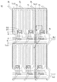
まず、図1及び図2を参照して本発明の実施の形態に係るタッチセンサ一体型表示装置について説明する。図1は、本発明の実施の形態に係るタッチセンサ一体型表示装置を概略的に示す一部分解斜視図であり、図2は、本発明の第1実施の形態に係るタッチセンサ一体型表示装置の共通電極兼用タッチ駆動電極と、非タッチ駆動電極及びタッチセンシング電極との関係を概略的に示す平面図である。 First, a touch sensor integrated display device according to an embodiment of the present invention will be described with reference to FIGS. 1 and 2. FIG. 1 is a partially exploded perspective view schematically showing a touch sensor integrated display device according to an embodiment of the present invention, and FIG. 2 is a touch sensor integrated display device according to the first embodiment of the present invention. It is a top view which shows roughly the relationship between the touch drive electrode which also serves as a common electrode, a non-touch drive electrode, and a touch sensing electrode.
図1を参照すると、本発明の実施の形態に係るタッチセンサ一体型表示装置は、液晶層(図示せず)を挟んで形成される薄膜トランジスタアレイTFTAとカラーフィルタアレイCFAとを備える液晶表示パネルLCPを含む。 Referring to FIG. 1, a touch sensor integrated display device according to an embodiment of the present invention includes a liquid crystal display panel LCP including a thin film transistor array TFTA and a color filter array CFA formed with a liquid crystal layer (not shown) interposed therebetween. including.
薄膜トランジスタアレイTFTAは、第1基板SUB1上に第1方向(例えば、x方向)に並行するように形成された複数のゲートラインG1、G2と、前記複数のゲートラインG1、G2と互いに交差するように第2方向(例えば、y方向)に並行するように形成されたデータラインD1、D2と、ゲートラインG1、G2及びデータラインD1、D2が交差によって定義される領域に位置する液晶セルと、ゲートラインG1、G2及びデータラインD1、D2が交差する領域に形成される薄膜トランジスタTFTと、液晶セルにデータ電圧を充電させるための複数の画素電極Pxと、前記複数の画素電極Pxと共に電界を形成するように配置された共通電極(図示せず)と、を含む。 The thin film transistor array TFTA has a plurality of gate lines G1 and G2 formed on the first substrate SUB1 so as to be parallel to the first direction (for example, the x direction), and intersects the plurality of gate lines G1 and G2. Data lines D1 and D2 formed to be parallel to the second direction (for example, the y direction), and liquid crystal cells located in a region defined by the intersection of the gate lines G1 and G2 and the data lines D1 and D2, A thin film transistor TFT formed in a region where the gate lines G1 and G2 and the data lines D1 and D2 intersect, a plurality of pixel electrodes Px for charging a liquid crystal cell with a data voltage, and an electric field together with the plurality of pixel electrodes Px And a common electrode (not shown) arranged to be.
カラーフィルタアレイCFAは、第2基板SUB2上に形成されるブラックマトリックス及びカラーフィルタ(図示せず)を含む。液晶表示パネルLCPの第1基板SUB1及び第2基板SUB2の外面には、それぞれ偏光板POL1、POL2が付着され、液晶と接する第1及び第2基板SUB1、SUB2の内面には、液晶のプレチルト角を設定するための配向膜(図示せず)がそれぞれ形成される。液晶表示パネルLCPのカラーフィルタアレイCFAと薄膜トランジスタアレイTFTAとの間には、液晶セルのセルギャップ(cell gap)を維持するためのカラムスペーサー(column spacer)が形成されることができる。 The color filter array CFA includes a black matrix and a color filter (not shown) formed on the second substrate SUB2. Polarizing plates POL1 and POL2 are attached to the outer surfaces of the first substrate SUB1 and the second substrate SUB2 of the liquid crystal display panel LCP, respectively. Alignment films (not shown) for setting are respectively formed. A column spacer for maintaining a cell gap of the liquid crystal cell may be formed between the color filter array CFA and the thin film transistor array TFTA of the liquid crystal display panel LCP.
一方、共通電極は、TN(Twisted Nematic)モードとVA(Vertical Alignment)モードのような垂直電界駆動方式においては、第2基板SUB2に形成され、IPS(In Plane Switching)モードとFFS(Fringe Field Switching)モードのような水平電界駆動方式では、画素電極Pxと共に、第1基板SUB1上に形成される。以下の本発明の実施の形態においては、水平電界駆動方式を例に挙げて説明する。 On the other hand, the common electrode is formed on the second substrate SUB2 in the vertical electric field driving method such as the TN (Twisted Nematic) mode and the VA (Vertical Alignment) mode, and the IPS (In Plane Switching) mode and the FFS (Fringe Field Switching). In the horizontal electric field driving method such as the) mode, the pixel electrode Px is formed on the first substrate SUB1. In the following embodiments of the present invention, a horizontal electric field driving method will be described as an example.
図2を参照すると、本発明の第1実施の形態に係るタッチセンサ一体型表示装置の共通電極COMは、第1方向(例えば、x軸方向)と第2方向(例えば、y軸方向)に分割される複数の電極Tx11、Tx12、Tx21、Tx22、S1、S2からなる。図2の実施の形態で、分割された共通電極は、4つのグループ、すなわち、第1〜第4グループのタッチ駆動電極Tx11、Tx12、Tx21、TRx22と、2つのグループ、すなわち、第1及び第2グループの非タッチセンシング電極S1、S2と、を含む。第1〜第4グループのタッチ駆動電極Tx11、Tx12、Tx21、Tx22は、4つの第1乃至第4タッチ駆動領域TA1〜TA4にそれぞれ配置され、第1及び第2グループの非タッチセンシング電極S1、S2は、第1及び第2タッチセンシング領域SA1、SA2にそれぞれ配置される。第1タッチセンシング領域SA1は、第1及び第2タッチ駆動領域TA1、TA2との間に配置され、第2タッチセンシング領域SA2は、第3及び第4タッチ駆動領域TA3、TA4との間に配置される。第2タッチ駆動領域TA2と第3タッチ駆動領域TA3は、互いに隣接するように配置される。前記構成に応じて、第1及び第2タッチセンシング領域SA1、SA2との間には、第2及び第3タッチ駆動領域TA2、TA3が配置される。 Referring to FIG. 2, the common electrode COM of the touch sensor integrated display device according to the first embodiment of the present invention is arranged in a first direction (for example, x-axis direction) and a second direction (for example, y-axis direction). It consists of a plurality of divided electrodes Tx11, Tx12, Tx21, Tx22, S1, and S2. In the embodiment of FIG. 2, the divided common electrodes have four groups, that is, the first to fourth groups of touch drive electrodes Tx11, Tx12, Tx21, and TRx22, and two groups, that is, the first and first groups. Two groups of non-touch sensing electrodes S1, S2 are included. The first to fourth groups of touch drive electrodes Tx11, Tx12, Tx21, and Tx22 are disposed in the four first to fourth touch drive regions TA1 to TA4, respectively, and the first and second groups of non-touch sensing electrodes S1, S2 is disposed in each of the first and second touch sensing areas SA1 and SA2. The first touch sensing area SA1 is disposed between the first and second touch drive areas TA1, TA2, and the second touch sensing area SA2 is disposed between the third and fourth touch drive areas TA3, TA4. Is done. The second touch drive area TA2 and the third touch drive area TA3 are disposed adjacent to each other. Depending on the configuration, the second and third touch drive areas TA2 and TA3 are disposed between the first and second touch sensing areas SA1 and SA2.
第1タッチ駆動領域TA1には、10行3列の第1−1タッチ駆動電極Tx11が配置され、第1グループのタッチ駆動電極Tx11が形成される。また、第1タッチ駆動領域TA1には、3列に配置された第1−1タッチ駆動電極Tx11と接触するタッチセンシング電極の接続配線がy軸方向に沿って配列される。すなわち、3列の第1−1タッチ駆動電極Tx11とそれぞれ接触する3列の第1−1タッチ駆動電極の接続配線Tc11がy軸方向に配列される。 In the first touch drive area TA1, 10 rows and 3 columns of 1-1 touch drive electrodes Tx11 are arranged to form a first group of touch drive electrodes Tx11. In the first touch drive area TA1, connection wirings of touch sensing electrodes that are in contact with the first to first touch drive electrodes Tx11 arranged in three columns are arranged along the y-axis direction. That is, the connection wiring Tc11 of the three columns of the 1-1 touch drive electrodes that are in contact with the three columns of the 1-1 touch drive electrodes Tx11 are arranged in the y-axis direction.
第2タッチ駆動領域TA2には、10行3列の第1−2タッチ駆動電極Tx12が配置され、第2グループのタッチ駆動電極Tx12を形成する。また、第2タッチ駆動領域TA2には、3列に配置された第1−2タッチ駆動電極Tx12と接触するタッチ駆動電極の接続配線がy軸方向に沿って配列される。すなわち、3列の第1−2タッチ駆動電極Tx12とそれぞれ接触する3列の第1−2タッチ駆動電極の接続配線Tc12がy軸方向に配列される。 In the second touch drive area TA2, the first and second touch drive electrodes Tx12 of 10 rows and 3 columns are arranged to form the second group of touch drive electrodes Tx12. Further, in the second touch drive area TA2, connection wirings of the touch drive electrodes that are in contact with the 1-2 touch drive electrodes Tx12 arranged in three rows are arranged along the y-axis direction. That is, the connection wiring Tc12 of the first and second touch drive electrodes in three rows that are in contact with the first and second touch drive electrodes Tx12 in the three rows are arranged in the y-axis direction.
第3タッチ駆動領域TA3には、10行3列の第2−1タッチ駆動電極Tx21が配置され、第3グループのタッチ駆動電極Tx21を形成する。また、第3タッチ駆動領域TA3には、3列に配置された第2−1タッチ駆動電極Tx21と接触するタッチ駆動電極の接続配線がy軸方向に沿って配列される。すなわち、3列の第2−1タッチ駆動電極Tx21とそれぞれ接触する3列の第2−1タッチ駆動電極の接続配線Tc21がy軸方向に配列される。 In the third touch drive area TA3, 2-1 touch drive electrodes Tx21 of 10 rows and 3 columns are arranged to form a third group of touch drive electrodes Tx21. Further, in the third touch drive area TA3, the connection wirings of the touch drive electrodes that are in contact with the 2-1 touch drive electrodes Tx21 arranged in three rows are arranged along the y-axis direction. That is, the connection lines Tc21 of the three rows of the 2-1 touch drive electrodes that are in contact with the three rows of the 2-1 touch drive electrodes Tx21 are arranged in the y-axis direction.
第4タッチ駆動領域TA4には、10行3列の第2−2タッチ駆動電極Tx22が配置され、第4グループのタッチ駆動電極Tx22を形成する。また、第4タッチ駆動領域TA4には、3列に配置された第2−2タッチ駆動電極Tx22と接触するタッチ駆動電極の接続配線がy軸方向に沿って配列される。すなわち、3列の第2−2タッチ駆動電極Tx22とそれぞれ接触する3列の第2−2タッチ駆動電極の接続配線Tc22がy軸方向に配列される。 In the fourth touch drive area TA4, 2-2 touch drive electrodes Tx22 of 10 rows and 3 columns are arranged to form a fourth group of touch drive electrodes Tx22. In the fourth touch drive area TA4, touch drive electrode connection wires that contact the 2-2 touch drive electrodes Tx22 arranged in three rows are arranged along the y-axis direction. That is, the connection lines Tc22 of the three rows of the 2-2 touch drive electrodes that are in contact with the three rows of the 2-2 touch drive electrodes Tx22 are arranged in the y-axis direction.
第1タッチセンシング領域SA1には、10行3列の第1非タッチセンシング電極S1が配置され、第1グループの非タッチセンシング電極S1が形成される。また、第1タッチセンシング領域SA1には、3列に配置された第1非タッチセンシング電極S1と接触する第1非タッチセンシング電極の接続配線がy軸方向に沿って配列される。すなわち、3列の第1非タッチセンシング電極S1とそれぞれ接触する3列の第1非タッチセンシング電極の接続配線Sc1がy軸方向に配列される。また、第1タッチセンシング領域SA1には、10行の第1非タッチセンシング電極S1と交互に10行の第1タッチセンシング電極Rx11、R21、Rx31、Rx32、... Rx101が配置され、10行の第1タッチセンシング電極Rx11、R21、Rx31、Rx32、... Rx101とそれぞれ接触する第1乃至第10のタッチセンシング電極の接続配線Rc1〜Rc10がx軸方向に配列される。 In the first touch sensing area SA1, 10 rows and 3 columns of first non-touch sensing electrodes S1 are arranged to form a first group of non-touch sensing electrodes S1. In the first touch sensing area SA1, the connection wires of the first non-touch sensing electrodes that are in contact with the first non-touch sensing electrodes S1 arranged in three rows are arranged along the y-axis direction. That is, the connection lines Sc1 of the three rows of first non-touch sensing electrodes that are in contact with the three rows of first non-touch sensing electrodes S1 are arranged in the y-axis direction. The first touch sensing area SA1 includes 10 rows of first non-touch sensing electrodes S1 and 10 rows of first touch sensing electrodes Rx11, R21, Rx31, Rx32,. The first to tenth touch sensing electrode connection wires Rc1 to Rc10 that are in contact with the first touch sensing electrodes Rx11, R21, Rx31, Rx32,... Rx101 are arranged in the x-axis direction.
第2タッチセンシング領域SA2には、10行3列の第2非タッチセンシング電極S2が配置され、第2グループの非タッチセンシング電極S2が形成される。また、第2タッチセンシング領域SA2には、3列に配置された第2非タッチセンシング電極S2と接触する第2非タッチセンシング電極の接続配線がy軸方向に沿って配列される。すなわち、3列の第2非タッチセンシング電極S2と、それぞれ接触する3列の第2非タッチセンシング電極の接続配線Sc2がy軸方向に配列される。そして、第2タッチセンシング領域SA2には、10行の第2非タッチセンシング電極S1と交互に10行のタッチセンシング電極Rx12、Rx22、Rx32、… Rx102が配置され、10行の第2タッチセンシング電極Rx12、Rx22、Rx32、... Rx102とそれぞれ接触する第1乃至第10のタッチセンシング電極の接続配線Rc1〜Rc10がx軸方向に配列される。 In the second touch sensing area SA2, 10 rows and 3 columns of second non-touch sensing electrodes S2 are arranged, and a second group of non-touch sensing electrodes S2 is formed. Further, in the second touch sensing area SA2, connection wirings of the second non-touch sensing electrodes that are in contact with the second non-touch sensing electrodes S2 arranged in three rows are arranged along the y-axis direction. That is, three rows of second non-touch sensing electrodes S2 and connection wires Sc2 of the three rows of second non-touch sensing electrodes that are in contact with each other are arranged in the y-axis direction. In the second touch sensing area SA2, 10 rows of second non-touch sensing electrodes S1 and 10 rows of touch sensing electrodes Rx12, Rx22, Rx32,... Rx102 are arranged, and 10 rows of second touch sensing electrodes. Rx12, Rx22, Rx32,... Rx102 contact wirings Rc1 to Rc10 that are in contact with Rx102 are arranged in the x-axis direction.
第1乃至第10タッチセンシング電極の接続配線Rc1〜Rc10は、図2に示すように、第1及び第2タッチセンシング領域SA1、SA2から延長され、第1乃至第4タッチ駆動領域TA1〜TA4まで配列され、第1乃至第4のタッチ駆動領域TA1〜TA4内で、第1−1、第1−2、第2−1及び第2−2タッチ駆動電極の接続配線Tc11、Tc12、Tc21、Tc22と交差するように配置される。 As shown in FIG. 2, the connection wires Rc1 to Rc10 of the first to tenth touch sensing electrodes are extended from the first and second touch sensing areas SA1 and SA2 to the first to fourth touch driving areas TA1 to TA4. Within the first to fourth touch drive areas TA1 to TA4, the connection wirings Tc11, Tc12, Tc21, Tc22 of the 1-1, 1-2, 2-1 and 2-2 touch drive electrodes are arranged. Arranged so as to intersect.
このような構成において、第1タッチ駆動領域TA1に配置された第1−1タッチ駆動電極Tx11と第2タッチ駆動領域TA2に配置された第1−2タッチ駆動電極Tx12は、それらと接触する第1−1タッチ駆動電極の接続配線Tc11の一端部と第1−2タッチ駆動電極の接続配線Tc12の一端部とを接続する接続配線を介して、第1タッチ駆動ルーティング配線TW1に接続される。第1−1タッチ駆動電極の接続配線Tc11と第1−2タッチ駆動電極の接続配線Tc12の他端部は、互いに接続された後、静電気放電回路ESDを介して接地配線GWに接続される。 In such a configuration, the first-first touch drive electrode Tx11 arranged in the first touch drive area TA1 and the first-2 touch drive electrode Tx12 arranged in the second touch drive area TA2 are in contact with them. The 1-1 touch drive electrode connection wiring Tc11 is connected to the first touch drive routing wiring TW1 via a connection wiring that connects one end of the first touch drive electrode connection wiring Tc12 and one end of the 1-2 touch drive electrode connection wiring Tc12. The other ends of the first-first touch drive electrode connection wiring Tc11 and the first-second touch drive electrode connection wiring Tc12 are connected to each other and then connected to the ground wiring GW via the electrostatic discharge circuit ESD.
また、第3タッチ駆動領域TA3に配置された第2−1タッチ駆動電極Tx21と第4タッチ駆動領域TA4に配置された第2−2タッチ駆動電極Tx22は、それらと接触する第2−1タッチ駆動電極の接続配線Tc21の一端部と第2−2タッチ駆動電極の接続配線Tc22の一端部とを接続する接続配線を介して、第2タッチ駆動ルーティング配線TW2に接続される。第2−1タッチ駆動電極の接続配線Tc21と第2−2タッチ駆動電極の接続配線Tc22の他端部は、互いに接続された後、他の静電気放電回路ESDを介して接地配線GWに接続される。 The 2-1 touch drive electrode Tx21 arranged in the third touch drive area TA3 and the 2-2 touch drive electrode Tx22 arranged in the fourth touch drive area TA4 are in contact with the 2-1 touch. The drive electrode connection line Tc21 is connected to the second touch drive routing line TW2 via a connection line that connects one end of the drive line connection line Tc21 and one end of the 2-2 touch drive electrode connection line Tc22. The other ends of the connection wiring Tc21 of the 2-1 touch drive electrode and the connection wiring Tc22 of the 2-2 touch drive electrode are connected to each other and then connected to the ground wiring GW through another electrostatic discharge circuit ESD. The
第1及び第2タッチ駆動ルーティング配線TW1、TW2は、第1及び第2タッチ駆動ルーティングパッドTP1、TP2にそれぞれ接続され、第1−1及び第1−2タッチ駆動電極Tx11、Tx12と第2−1及び第2−2タッチ駆動電極Tx21、Tx22にタッチ駆動のためのタッチ駆動電圧を供給する。 The first and second touch drive routing lines TW1 and TW2 are connected to the first and second touch drive routing pads TP1 and TP2, respectively, and the first and second touch drive electrodes Tx11 and Tx12 are connected to the second and second touch drive routing lines TP1 and TP2, respectively. A touch driving voltage for touch driving is supplied to the first and second-2 touch driving electrodes Tx21 and Tx22.
図2に示された実施の形態では、タッチ駆動電極が、第1−1及び第1−2タッチ駆動電極Tx11、TRx12と、第1−1及び第1−2タッチ駆動電極の接続配線Tc11、Tc12と、からなる第1タッチ駆動ラインと、第2−1及び第2−2タッチ駆動電極Tx21、Tx22と、第2−1及び第2−2タッチ駆動電極の接続配線Tc21、Tc22と、からなる第2タッチ駆動ラインの例を示している。しかし、図2の実施の形態は、単に例示的なものに過ぎず、必要に応じて接続部により接続されるタッチ駆動電極の接続配線の数を調整して、タッチ駆動ラインの数を決定することができる。 In the embodiment shown in FIG. 2, the touch drive electrodes include the 1-1 and 1-2 touch drive electrodes Tx11 and TRx12, and the connection wiring Tc11 of the 1-1 and 1-2 touch drive electrodes. A first touch drive line composed of Tc12, 2-1 and 2-2 touch drive electrodes Tx21 and Tx22, and connection wirings Tc21 and Tc22 of the 2-1 and 2-2 touch drive electrodes. An example of the second touch drive line is shown. However, the embodiment of FIG. 2 is merely an example, and the number of touch drive lines is determined by adjusting the number of connection wirings of the touch drive electrodes connected by the connection unit as necessary. be able to.
一方、第1タッチセンシング領域SA1に配置された第1非タッチセンシング電極S1は、それらと接触する第1非タッチセンシング電極の接続配線Sc1の一端部に接続する接続部によって接地配線GWに接続される。また、第2タッチセンシング領域SA2に配置された第2非タッチセンシング電極S2は、それらと接触する第2非タッチセンシング電極の接続配線Sc2の一端部が相互接続された後、接地配線GWに接続される。 On the other hand, the first non-touch sensing electrode S1 disposed in the first touch sensing area SA1 is connected to the ground wiring GW by a connection portion connected to one end portion of the connection wiring Sc1 of the first non-touch sensing electrode in contact therewith. The In addition, the second non-touch sensing electrode S2 disposed in the second touch sensing area SA2 is connected to the ground wiring GW after one end of the connection wiring Sc2 of the second non-touch sensing electrode in contact with the second non-touch sensing electrode SA2 is interconnected. Is done.
第1乃至第5タッチセンシング電極Rx11、Rx12;Rx21、Rx22;Rx31、Rx32;Rx41、Rx42;Rx51、Rx52は、それらと接触する第1乃至第5タッチセンシング電極の接続配線Rc1〜Rc5の一端部に接続する接続部によって第1タッチセンシングルーティング配線RW1に接続される。第1〜第5タッチセンシング電極の接続配線Rc1〜Rc5の他端部は、互いに接続された後、他の静電気放電回路ESDを介して接地配線GWに接続される。 The first to fifth touch sensing electrodes Rx11, Rx12; Rx21, Rx22; Rx31, Rx32; Rx41, Rx42; Rx51, Rx52 are one end portions of the connection wirings Rc1 to Rc5 of the first to fifth touch sensing electrodes in contact with them. Is connected to the first touch sensing routing wiring RW1 by a connecting portion connected to The other ends of the connection wirings Rc1 to Rc5 of the first to fifth touch sensing electrodes are connected to each other and then connected to the ground wiring GW through another electrostatic discharge circuit ESD.
第6乃至第10タッチセンシング電極Rx61、Rx62;Rx71、Rx72;Rx81、Rx82;Rx91、Rx92;Rx101、Rx102は、それらと接触する第6乃至第10タッチセンシング電極の接続配線Rc6〜Rc10の一端部を位置1つに接続する接続配線により、第2タッチセンシングルーティング配線RW2に接続される。第6乃至第10タッチセンシング電極の接続配線R6〜Rc10の他端部は、互いに接続された後、他の静電気放電回路ESDを介して接地配線GWに接続される。 Sixth to tenth touch sensing electrodes Rx61, Rx62; Rx71, Rx72; Rx81, Rx82; Rx91, Rx92; Rx101, Rx102 are one end portions of connection wirings Rc6 to Rc10 of the sixth to tenth touch sensing electrodes in contact with them. Is connected to the second touch sensing routing wiring RW2 by a connection wiring that connects to one position. The other ends of the connection wirings R6 to Rc10 of the sixth to tenth touch sensing electrodes are connected to each other and then connected to the ground wiring GW through another electrostatic discharge circuit ESD.
第1及び第2タッチセンシングルーティング配線RW1、RW2は、第1及び第2タッチセンシングルーティングパッドRP1、RP2にそれぞれ接続されて、第1〜第5のタッチセンシング電極Rx11、Rx12;Rx21、Rx22;Rx31、Rx32;Rx41、Rx42;Rx51、Rx52と第6乃至第10タッチセンシング電極Rx61、Rx62;Rx71、Rx72;Rx81、Rx82;Rx91、Rx92;Rx101、Rx102からセンシングされたセンシング電圧を、第1乃至第10タッチセンシング電極の接続配線Rc1〜Rc5、Rc6〜Rc10を介して、タッチプロセッサ(図示せず)に供給する。 The first and second touch sensing routing lines RW1 and RW2 are connected to the first and second touch sensing routing pads RP1 and RP2, respectively, and the first to fifth touch sensing electrodes Rx11, Rx12; Rx21, Rx22; Rx31 , Rx32; Rx41, Rx42; Rx51, Rx52 and the sixth to tenth touch sensing electrodes Rx61, Rx62; Rx71, Rx72; Rx81, Rx82; Rx91, Rx92; 10 touch sensing electrodes are connected to a touch processor (not shown) via connection wirings Rc1 to Rc5 and Rc6 to Rc10.
図2に示された実施の形態においては、タッチセンシング電極が2つのタッチセンシングラインからなる構成の例、すなわち、第1〜第5のタッチセンシング電極Rx11、Rx12;Rx21、Rx22;Rx31、Rx32;Rx41、Rx42;Rx51、Rx52及び第1〜第5のタッチセンシング電極の接続配線Rc1〜Rc5からなる、第1タッチセンシングラインと、第6乃至第10タッチセンシング電極Rx61、Rx62;Rx71、Rx72;Rx81、Rx82;Rx91、Rx92;Rx101、Rx102及び第6乃至第10タッチセンシング電極の接続配線Rc6〜Rc10からなる第2タッチセンシングラインの例を示している。しかし、図2の実施の形態は、単に例示的なものに過ぎず、必要に応じて接続部により接続されたタッチセンシング電極の接続配線の数を調整して、タッチセンシングラインの数を決定することができる。 In the embodiment shown in FIG. 2, an example of a configuration in which the touch sensing electrode includes two touch sensing lines, that is, first to fifth touch sensing electrodes Rx11, Rx12; Rx21, Rx22; Rx31, Rx32; Rx41, Rx42; Rx51, Rx52 and first to fifth touch sensing electrode connection wirings Rc1 to Rc5, a first touch sensing line and sixth to tenth touch sensing electrodes Rx61, Rx62; Rx71, Rx72; Rx81 , Rx82; Rx91, Rx92; Rx101, Rx102 and an example of the second touch sensing line including the connection wirings Rc6 to Rc10 of the sixth to tenth touch sensing electrodes. However, the embodiment of FIG. 2 is merely illustrative, and the number of touch sensing lines is determined by adjusting the number of connection wires of the touch sensing electrodes connected by the connection unit as necessary. be able to.
以上説明したタッチ駆動電極Tx11、Tx12;Tx21、Tx22及び非タッチセンシング電極S1、S2は全て共通電極COMとしての機能を兼ねており、水平電界方式の表示装置において、これらは画素電極Pxと共に薄膜トランジスタアレイTFTAの第1基板SUB1に形成され、画素電極Pxは、ゲートラインとデータラインの交差によって定義される領域に形成される。 The touch drive electrodes Tx11, Tx12; Tx21, Tx22 and the non-touch sensing electrodes S1, S2 described above all function as a common electrode COM. In the horizontal electric field type display device, these are the thin film transistor array together with the pixel electrode Px. Formed on the first substrate SUB1 of the TFTA, the pixel electrode Px is formed in a region defined by the intersection of the gate line and the data line.
一方、共通電極COMとしての機能を兼ねるタッチ駆動電極Tx11、Tx12;Tx21、Tx22と非タッチセンシング電極S1、S2のそれぞれは、単位画素電極(色を表示するために、必要な複数のサブ画素で、本発明の実施の形態では、3つのサブ画素からなる単位画素電極である)に対応するように形成することができる。 On the other hand, each of the touch drive electrodes Tx11, Tx12; Tx21, Tx22 and the non-touch sensing electrodes S1, S2 that also function as the common electrode COM is a unit pixel electrode (a plurality of sub-pixels necessary for displaying colors). In the embodiment of the present invention, the unit pixel electrode is formed of three subpixels).
次に、図3A及び図3Bを参照して、タッチセンシング領域SA1、SA2で共通電極(非タッチセンシング電極)が画素電極の上層に形成される場合の本発明の第1実施の形態に係るタッチセンサ一体型表示装置について説明する。図3Aは、図2に示された領域R1において共通電極(非タッチセンシング電極)が画素電極上層に形成される場合の例を示す平面図であり、図3Bは、図3AのI−I’ラインに沿って取った断面図である。 Next, referring to FIGS. 3A and 3B, the touch according to the first embodiment of the present invention in the case where a common electrode (non-touch sensing electrode) is formed on the upper layer of the pixel electrode in the touch sensing areas SA1 and SA2. A sensor-integrated display device will be described. 3A is a plan view illustrating an example in which a common electrode (non-touch sensing electrode) is formed on the upper layer of the pixel electrode in the region R1 illustrated in FIG. 2, and FIG. 3B is a cross-sectional view taken along line II ′ of FIG. 3A. It is sectional drawing taken along the line.
以下の説明では、説明の簡略化のために、2つの非タッチセンシング電極S1、S1の一部領域とそれに隣接する2つのタッチセンシング電極Rx11、Rx21の一部領域を含む領域R1に配置される画素電極Pxを中心に説明する。本実施の形態の図面でPxは、色を表示するために必要なサブ画素として、3つのサブ画素が一つの単位画素電極を形成する場合を例に挙げた。以下の説明では、単位画素電極を構成する各サブ画素電極を単純に画素電極と称する。 In the following description, for simplification of description, it is arranged in a region R1 including a partial region of the two non-touch sensing electrodes S1 and S1 and a partial region of the two touch sensing electrodes Rx11 and Rx21 adjacent thereto. The description will focus on the pixel electrode Px. In the drawings of this embodiment, Px is given as an example in which three subpixels form one unit pixel electrode as a subpixel necessary for displaying a color. In the following description, each sub pixel electrode constituting the unit pixel electrode is simply referred to as a pixel electrode.
図2、図3A及び図3Bを参照すると、本発明の第1実施の形態に係るタッチセンサ一体型表示装置は、薄膜トランジスタアレイTFTAの基板SUB1上に互いに交差するように形成されるゲートラインGL及びデータラインDLと、前記ゲートラインGLとデータラインDLの交差領域に形成される薄膜トランジスタTFTと、ゲートラインGLとデータラインDLの交差によって定義される領域に形成される画素電極Pxと、前記画素電極Pxと対向する共通電極COMと、を含む。本発明の第1実施の形態では、共通電極COMが非タッチセンシング電極S1の機能を兼ねるので、以下の説明では、必要に応じて、「共通電極COM」、「非タッチセンシング電極S1」「共通電極兼用非タッチセンシング電極S1」、または「非タッチセンシング電極兼用共通電極COM」と称する。 Referring to FIGS. 2, 3A, and 3B, the touch sensor integrated display device according to the first embodiment of the present invention includes gate lines GL formed on the substrate SUB1 of the thin film transistor array TFTA so as to intersect with each other. A data line DL, a thin film transistor TFT formed in an intersection region of the gate line GL and the data line DL, a pixel electrode Px formed in a region defined by the intersection of the gate line GL and the data line DL, and the pixel electrode A common electrode COM facing Px. In the first embodiment of the present invention, since the common electrode COM also functions as the non-touch sensing electrode S1, in the following description, “common electrode COM”, “non-touch sensing electrode S1”, “common” are used as necessary. It is referred to as “non-touch sensing electrode S1 serving as electrode” or “common electrode COM serving as non-touch sensing electrode”.
前記構成において、基板SUB上には、ゲートラインGLが形成され、その上部には、ゲート絶縁膜GIが形成される。ゲート絶縁膜GI上では、薄膜トランジスタTFTを構成する活性層A、ソース電極S及びドレイン電極Dが形成される。 In the above configuration, the gate line GL is formed on the substrate SUB, and the gate insulating film GI is formed on the gate line GL. On the gate insulating film GI, an active layer A, a source electrode S, and a drain electrode D constituting the thin film transistor TFT are formed.
薄膜トランジスタTFTは、基板SUB上に形成されるゲートラインGLから延長されるゲート電極Gと、ゲートラインGL及びゲート電極Gをカバーするゲート絶縁膜GI上でゲート電極Gと対応する領域に形成される活性層Aと、活性層Aの一部を露出させるようにゲート絶縁膜GI上に分離されて形成されるデータラインDLから延長されるソース電極S及びドレイン電極Dと、を含む。 The thin film transistor TFT is formed in a region corresponding to the gate electrode G on the gate electrode G extending from the gate line GL formed on the substrate SUB and the gate insulating film GI covering the gate line GL and the gate electrode G. The active layer A includes a source electrode S and a drain electrode D extended from the data line DL formed on the gate insulating film GI so as to expose a part of the active layer A.
前記実施の形態において、薄膜トランジスタは、ゲート電極がソース/ドレイン電極の下層に形成されるボトムゲート構造(gate bottom structure)の薄膜トランジスタを例に挙げて説明したが、本発明はこれに限定されるものではなく、ゲート電極がソース/ドレイン領域の上部に形成されるトップゲート構造(gate top structure)の薄膜トランジスタも含むものと理解しなければならない。トップゲート構造の薄膜トランジスタは、公知の構成なので、それに対する詳細な説明は省略する。 In the above embodiment, the thin film transistor has been described by taking a thin film transistor having a gate bottom structure in which a gate electrode is formed below a source / drain electrode, but the present invention is not limited thereto. Instead, it should be understood to include a gate top structure thin film transistor in which the gate electrode is formed on top of the source / drain regions. Since the top gate thin film transistor has a known structure, a detailed description thereof will be omitted.
薄膜トランジスタTFTとデータラインDLが形成されたゲート絶縁膜GI上に、薄膜トランジスタTFTとデータラインDLをカバーする第1保護膜PAS1が形成され、第1保護膜PAS上に、平坦化のためのフォトアクリルなどの有機絶縁膜INSが形成される。有機絶縁膜INSと、第1保護膜PAS1とには、ドレイン電極Dの一部を露出させるコンタクトホールCHが形成される。 A first protective film PAS1 that covers the thin film transistor TFT and the data line DL is formed on the gate insulating film GI on which the thin film transistor TFT and the data line DL are formed, and a photoacrylic for planarization is formed on the first protective film PAS. An organic insulating film INS such as is formed. A contact hole CH exposing a part of the drain electrode D is formed in the organic insulating film INS and the first protective film PAS1.
有機絶縁膜INS上には、データラインDLとゲートラインGLの交差によって定義される画素領域内にそれぞれ画素電極Pxが形成される。画素電極Pxは、有機絶縁膜INS及び第1保護膜PAS1を貫通するコンタクトホールCHを通じて、薄膜トランジスタTFTのドレイン電極Dと接触するように形成される。また、有機絶縁膜INS上には、y軸方向に配列された隣接する画素電極Pxとの間に配置され、ゲートラインGLと並行するタッチセンシング電極Rx11が形成される。タッチセンシング電極Rx11は、後述する非タッチセンシング電極S1のボトルネック部Sbと交差する領域の幅が狭く形成されたボトルネック部Rbを含む。タッチセンシング電極Rx11上には、ゲートラインGLと並行するようにタッチセンシング電極の接続配線Rc1が形成される。 On the organic insulating film INS, pixel electrodes Px are formed in pixel regions defined by the intersections of the data lines DL and the gate lines GL, respectively. The pixel electrode Px is formed so as to be in contact with the drain electrode D of the thin film transistor TFT through the contact hole CH that penetrates the organic insulating film INS and the first protective film PAS1. Further, on the organic insulating film INS, a touch sensing electrode Rx11 that is disposed between the adjacent pixel electrodes Px arranged in the y-axis direction and parallel to the gate line GL is formed. The touch sensing electrode Rx11 includes a bottleneck portion Rb formed with a narrow width in a region intersecting with a bottleneck portion Sb of the non-touch sensing electrode S1 described later. On the touch sensing electrode Rx11, a connection wiring Rc1 for the touch sensing electrode is formed in parallel with the gate line GL.
画素電極Pxと、タッチセンシング電極Rx11及びタッチセンシング電極の接続配線Rc1が形成された有機絶縁膜INS上には、第2保護膜PAS2が形成される。 A second protective film PAS2 is formed on the organic insulating film INS on which the pixel electrode Px, the touch sensing electrode Rx11, and the connection wiring Rc1 for the touch sensing electrode are formed.
第2保護膜PAS2上に、データラインDLと重ねるように、非タッチセンシング電極の接続配線Sc1が形成される。非タッチセンシング電極の接続配線Sc1は、タッチセンシング電極Rx11のボトルネック部Rbを経由するように配置される。 A non-touch sensing electrode connection line Sc1 is formed on the second protective film PAS2 so as to overlap the data line DL. The connection wiring Sc1 for the non-touch sensing electrode is arranged so as to pass through the bottleneck portion Rb of the touch sensing electrode Rx11.
非タッチセンシング電極の接続配線Sc1が形成された第2保護膜PAS2上には、非タッチセンシング電極の接続配線Sc1をカバーするように共通電極兼用の非タッチセンシング電極S1が形成される。非タッチセンシング電極S1は、画素電極Pxと重畳されるように形成される。ディスプレイ駆動時の共通電圧が供給される非タッチセンシング電極S1は、画素電極Pxとの間に水平電界が形成されやすいように、複数のスリットSLを含む。したがって、有機絶縁層INS上に形成される画素電極Pxは、スリットを有しないように形成され、第2保護層PAS2上に形成される非タッチセンシング電極S1は、スリットSLを有するように形成される。 On the second protective film PAS2 on which the connection wiring Sc1 for the non-touch sensing electrode is formed, the non-touch sensing electrode S1 also serving as a common electrode is formed so as to cover the connection wiring Sc1 for the non-touch sensing electrode. The non-touch sensing electrode S1 is formed so as to overlap with the pixel electrode Px. The non-touch sensing electrode S1 to which a common voltage for driving the display is supplied includes a plurality of slits SL so that a horizontal electric field is easily formed between the non-touch sensing electrode S1 and the pixel electrode Px. Accordingly, the pixel electrode Px formed on the organic insulating layer INS is formed so as not to have a slit, and the non-touch sensing electrode S1 formed on the second protective layer PAS2 is formed so as to have a slit SL. The
次に、図4Aおよび図4Bを参照して、タッチセンシング領域SA1、SA2で画素電極が共通電極(非タッチセンシング電極)の上層に形成される場合の本発明の第1実施の形態の変形例に従うタッチセンサ一体型表示装置について説明する。図4Aは、図2に示された領域R1で画素電極が共通電極の上層に形成される場合の例を示す平面図であり、図4Bは、図4AのII−II’ラインに沿って取った断面図である。 Next, referring to FIGS. 4A and 4B, a modification of the first embodiment of the present invention in the case where the pixel electrode is formed in the upper layer of the common electrode (non-touch sensing electrode) in the touch sensing regions SA1 and SA2. Will be described. 4A is a plan view showing an example in which the pixel electrode is formed in the upper layer of the common electrode in the region R1 shown in FIG. 2, and FIG. 4B is taken along the line II-II ′ in FIG. 4A. FIG.
図2、図4A及び図4Bを参照すると、本発明の第1実施の形態の変形例に係るタッチセンサ一体型表示装置は、薄膜トランジスタアレイTFTAの基板SUB1上に互いに交差するように形成されるゲートラインGL及びデータラインDLと、前記ゲートラインGLとデータラインDLの交差領域に形成される薄膜トランジスタTFTと、ゲートラインGL及びデータラインDLの交差によって定義される領域に形成される画素電極Pxと、前記画素電極Pxと対向する共通電極COMと、を含む。本発明の第1実施の形態の変形例においても、本発明の第1実施の形態と同様に、共通電極COMが非タッチセンシング電極S1の機能を兼ねるので、以下の説明では、必要に応じて、「共通電極COM」、「非タッチセンシング電極S1」、「共通電極兼用非タッチセンシング電極S1」、または「非タッチセンシング電極兼用共通電極COM」と称する。 Referring to FIGS. 2, 4A and 4B, the touch sensor integrated display device according to the modification of the first embodiment of the present invention includes gates formed on the substrate SUB1 of the thin film transistor array TFTA so as to cross each other. A line GL and a data line DL, a thin film transistor TFT formed in an intersection region of the gate line GL and the data line DL, a pixel electrode Px formed in a region defined by the intersection of the gate line GL and the data line DL, A common electrode COM facing the pixel electrode Px. Also in the modification of the first embodiment of the present invention, the common electrode COM also serves as the function of the non-touch sensing electrode S1 as in the first embodiment of the present invention. , “Common electrode COM”, “non-touch sensing electrode S1”, “common electrode non-touch sensing electrode S1”, or “non-touch sensing electrode common electrode COM”.
前記構成において、基板SUB上には、ゲートラインGLが形成され、その上部には、ゲート絶縁膜GIが形成される。ゲート絶縁膜GI上では、薄膜トランジスタTFTを構成する活性層A、ソース電極Sおよびドレイン電極Dが形成される。 In the above configuration, the gate line GL is formed on the substrate SUB, and the gate insulating film GI is formed on the gate line GL. On the gate insulating film GI, an active layer A, a source electrode S, and a drain electrode D constituting the thin film transistor TFT are formed.
薄膜トランジスタTFTは、基板SUB上に形成されたゲートラインGLから延長されたゲート電極Gと、ゲートラインGL及びゲート電極Gをカバーするゲート絶縁膜GI上でゲート電極Gと対応する領域に形成される活性層Aと、活性層Aの一部を露出させるようにゲート絶縁膜GI上に分離されて形成されるデータラインDLから延長されるソース電極S及びドレイン電極Dと、を含む。 The thin film transistor TFT is formed in a region corresponding to the gate electrode G on the gate electrode G extending from the gate line GL formed on the substrate SUB and on the gate insulating film GI covering the gate line GL and the gate electrode G. The active layer A includes a source electrode S and a drain electrode D extended from the data line DL formed on the gate insulating film GI so as to expose a part of the active layer A.
前記実施の形態において、薄膜トランジスタは、ゲート電極がソース/ドレイン電極の下層に形成されるボトムゲート構造の薄膜トランジスタを例に挙げて説明したが、本発明はこれに限定されるものではなく、ゲート電極がソース/ドレイン領域の上部に形成されるトップゲート構造の薄膜トランジスタも含むものと理解しなければならない。トップゲート構造の薄膜トランジスタは、公知の構成なので、それに対する詳細な説明は省略する。 In the above-described embodiment, the thin film transistor has been described using the example of the bottom gate thin film transistor in which the gate electrode is formed below the source / drain electrode, but the present invention is not limited thereto, and the gate electrode Should be understood to include a thin film transistor having a top gate structure formed above the source / drain region. Since the top gate thin film transistor has a known structure, a detailed description thereof will be omitted.
薄膜トランジスタTFTとデータラインDLが形成されたゲート絶縁膜GI上には、薄膜トランジスタTFTとデータラインDLをカバーする第1保護膜PAS1が形成され、第1保護膜PAS1上には、平坦化のためのフォトアクリルなどの有機絶縁膜INSが形成される。有機絶縁膜INSには、ドレイン電極Dの一部と対応する位置の第1保護膜PAS1を露出させる第1コンタクトホールCH1が形成される。 A first protective film PAS1 that covers the thin film transistor TFT and the data line DL is formed on the gate insulating film GI on which the thin film transistor TFT and the data line DL are formed. On the first protective film PAS1, a planarization film is formed. An organic insulating film INS such as photoacryl is formed. In the organic insulating film INS, a first contact hole CH1 that exposes the first protective film PAS1 at a position corresponding to a part of the drain electrode D is formed.
第1コンタクトホールCH1が形成された有機絶縁膜INS上には、ボトルネック部Sbによって互いに接続される共通電極COM兼用の非タッチセンシング電極S1が形成される。すなわち、2つの非タッチセンシング電極S1がデータラインDLと並行し、少なくとも一つのボトルネック部Sbにより接続されるように、有機絶縁膜INS上に形成される。非タッチセンシング電極S1上には、データラインDLと重畳される非タッチセンシング電極の接続配線Sc1が形成される。非タッチセンシング電極の接続配線Sc1は、ボトルネック部Sbを経由するように配置される。 On the organic insulating film INS in which the first contact hole CH1 is formed, the non-touch sensing electrode S1 that is also used as the common electrode COM and is connected to each other by the bottleneck portion Sb is formed. That is, the two non-touch sensing electrodes S1 are formed on the organic insulating film INS so as to be connected to at least one bottleneck portion Sb in parallel with the data line DL. On the non-touch sensing electrode S1, a connection wiring Sc1 of the non-touch sensing electrode that is overlapped with the data line DL is formed. The connection wiring Sc1 of the non-touch sensing electrode is arranged so as to pass through the bottleneck portion Sb.
非タッチセンシング電極S1と非タッチセンシング電極の接続配線Sc1が形成された有機絶縁膜INS上に、第2保護膜PAS2が形成される。有機絶縁膜INSの第1コンタクトホールCH1を介して露出される第1保護膜PAS1、及び第2保護膜PAS2には、薄膜トランジスタTFTのドレイン電極Dの一部を露出させる第2コンタクトホールCH2が形成される。 A second protective film PAS2 is formed on the organic insulating film INS on which the connection wiring Sc1 between the non-touch sensing electrode S1 and the non-touch sensing electrode is formed. A second contact hole CH2 exposing a part of the drain electrode D of the thin film transistor TFT is formed in the first protective film PAS1 and the second protective film PAS2 exposed through the first contact hole CH1 of the organic insulating film INS. Is done.
第2コンタクトホールCH2が形成された第2保護膜PAS2上には、データラインDLとゲートラインGLの交差によって定義される画素領域内にそれぞれ画素電極Pxが形成される。また、第2保護膜PAS2上には、データラインDLの方向、すなわち、y軸方向に隣接する2つの画素電極Pxとの間で、ゲートラインGLと並行する方向(x軸方向)にタッチセンシング電極の接続配線Rc1が形成される。タッチセンシング電極の接続配線Rc1が形成された第2保護膜PAS2上には、タッチセンシング電極の接続配線Rc1をカバーするように、ゲートラインGLと平行にタッチセンシング電極Rx11が形成される。タッチセンシング電極Rx11は、隣接する非タッチセンシング電極S1を接続するボトルネック部Sbと交差する領域でボトルネック部Rbを有するように形成される。 On the second protective film PAS2 in which the second contact hole CH2 is formed, pixel electrodes Px are respectively formed in the pixel regions defined by the intersections of the data lines DL and the gate lines GL. On the second protective film PAS2, touch sensing is performed in the direction of the data line DL, that is, in the direction parallel to the gate line GL (x-axis direction) between two pixel electrodes Px adjacent in the y-axis direction. An electrode connection wiring Rc1 is formed. On the second protective film PAS2 on which the touch sensing electrode connection wiring Rc1 is formed, the touch sensing electrode Rx11 is formed in parallel with the gate line GL so as to cover the touch sensing electrode connection wiring Rc1. The touch sensing electrode Rx11 is formed so as to have a bottleneck portion Rb in a region intersecting with the bottleneck portion Sb connecting the adjacent non-touch sensing electrodes S1.
画素電極Pxは、非タッチセンシング電極S1と重畳されるように形成される。画素電極Pxのそれぞれは、ディスプレイ駆動時共通電圧が供給される非タッチセンシング電極S1との間に水平電界が形成されやすいように複数のスリットSLを含む。したがって、有機絶縁層INS上に形成される非タッチセンシング電極S1は、スリットを有しないように形成され、第2保護層PAS2上に形成される画素電極Pxは、スリットSLを有するように形成される。 The pixel electrode Px is formed so as to overlap with the non-touch sensing electrode S1. Each of the pixel electrodes Px includes a plurality of slits SL so that a horizontal electric field is easily formed between the pixel electrode Px and the non-touch sensing electrode S1 to which a common voltage is supplied during display driving. Accordingly, the non-touch sensing electrode S1 formed on the organic insulating layer INS is formed so as not to have a slit, and the pixel electrode Px formed on the second protective layer PAS2 is formed so as to have a slit SL. The
次に、図5Aおよび図5Bを参照して、タッチ駆動領域TA1〜TA4で共通電極(タッチ駆動電極)が画素電極の上層に形成される場合の本発明の第1実施の形態に係るタッチセンサ一体型表示装置について説明する。図5Aは、図2に示された領域R2に共通電極(タッチ駆動電極)が画素電極上層に形成される場合の例を示す平面図であり、図5Bは、図5AのIII−III’ラインに沿って取る断面図である。 Next, with reference to FIGS. 5A and 5B, the touch sensor according to the first embodiment of the present invention in the case where the common electrode (touch drive electrode) is formed in the upper layer of the pixel electrode in the touch drive regions TA1 to TA4. The integrated display device will be described. FIG. 5A is a plan view showing an example in which a common electrode (touch drive electrode) is formed in the upper layer of the pixel electrode in the region R2 shown in FIG. 2, and FIG. 5B is a III-III ′ line in FIG. 5A. FIG.
図2、図5A及び図5Bを参照すると、本発明の第1実施の形態に係るタッチセンサ一体型表示装置は、薄膜トランジスタアレイTFTAの基板SUB1上に互いに交差するように形成されるゲートラインGL及びデータラインDLと、前記ゲートラインGLとデータラインDLとの交差領域に形成される薄膜トランジスタTFTと、ゲートラインGLとデータラインDLとの交差によって定義される領域に形成される画素電極Pxと、前記画素電極Pxと対向する共通電極COMと、を含む。本発明の第1実施の形態では、共通電極COMが非タッチ駆動電極Tx12の機能を兼ねるので、以下の説明では、必要に応じて、「共通電極COM」、「タッチ駆動電極Tx12」、「共通電極兼用タッチ駆動電極Tx12」、または「非タッチ駆動電極兼用共通電極COM」と称する。 Referring to FIGS. 2, 5A and 5B, the touch sensor integrated display device according to the first embodiment of the present invention includes gate lines GL formed to intersect each other on the substrate SUB1 of the thin film transistor array TFTA. A data line DL, a thin film transistor TFT formed in a crossing region of the gate line GL and the data line DL, a pixel electrode Px formed in a region defined by a crossing of the gate line GL and the data line DL, A common electrode COM facing the pixel electrode Px. In the first embodiment of the present invention, the common electrode COM also functions as the non-touch drive electrode Tx12. Therefore, in the following description, “common electrode COM”, “touch drive electrode Tx12”, “common” are used as necessary. This is referred to as “electrode drive touch electrode Tx12” or “non-touch drive electrode common electrode COM”.
前記構成において、基板SUB上には、ゲートラインGLが形成され、その上部には、ゲート絶縁膜GIが形成される。ゲート絶縁膜GI上では、薄膜トランジスタTFTを構成する活性層A、ソース電極Sおよびドレイン電極Dが形成される。 In the above configuration, the gate line GL is formed on the substrate SUB, and the gate insulating film GI is formed on the gate line GL. On the gate insulating film GI, an active layer A, a source electrode S, and a drain electrode D constituting the thin film transistor TFT are formed.
薄膜トランジスタTFTは、基板SUB上に形成されるゲートラインGLから延長されるゲート電極Gと、ゲートラインGL及びゲート電極Gをカバーするゲート絶縁膜GI上でゲート電極Gと対応する領域に形成される活性層Aと、活性層Aの一部を露出させるようにゲート絶縁膜GI上に分離されて形成されるデータラインDLから延長されるソース電極S及びドレイン電極Dと、を含む。 The thin film transistor TFT is formed in a region corresponding to the gate electrode G on the gate electrode G extending from the gate line GL formed on the substrate SUB and the gate insulating film GI covering the gate line GL and the gate electrode G. The active layer A includes a source electrode S and a drain electrode D extended from the data line DL formed on the gate insulating film GI so as to expose a part of the active layer A.
前記実施の形態において、薄膜トランジスタは、ゲート電極がソース/ドレイン電極の下層に形成されるボトムゲート構造(gate bottom structure)の薄膜トランジスタを例に挙げて説明したが、本発明はこれに限定されるものではなく、ゲート電極がソース/ドレイン領域の上部に形成されるトップゲート構造(gate top structure)の薄膜トランジスタも含むものと理解しなければならない。トップゲート構造の薄膜トランジスタは、公知の構成であるから、それに対する詳細な説明は省略する。 In the above embodiment, the thin film transistor has been described by taking a thin film transistor having a gate bottom structure in which a gate electrode is formed below a source / drain electrode, but the present invention is not limited thereto. Instead, it should be understood to include a gate top structure thin film transistor in which the gate electrode is formed on top of the source / drain regions. Since the thin film transistor having a top gate structure has a known configuration, detailed description thereof is omitted.
薄膜トランジスタTFTとデータラインDLが形成されたゲート絶縁膜GI上には、薄膜トランジスタTFT及びデータラインDLをカバーする第1保護膜PAS1が形成され、第1保護膜PAS1上に、平坦化のためのフォトアクリルなどの有機絶縁膜INSが形成される。有機絶縁膜INSと、第1保護膜PAS1には、ドレイン電極Dの一部を露出させるコンタクトホールCHが形成される。 A first protective film PAS1 that covers the thin film transistor TFT and the data line DL is formed on the gate insulating film GI on which the thin film transistor TFT and the data line DL are formed. A planarization photo film is formed on the first protective film PAS1. An organic insulating film INS such as acrylic is formed. A contact hole CH exposing a part of the drain electrode D is formed in the organic insulating film INS and the first protective film PAS1.
有機絶縁膜INS上には、データラインDLとゲートラインGLとの交差によって定義される画素領域内に、それぞれ画素電極Pxが形成される。画素電極Pxは、有機絶縁膜INS及び第1保護膜PAS1を貫通するコンタクトホールCHを通じて、薄膜トランジスタTFTのドレイン電極Dと接触するように形成される。有機絶縁膜INS上には、データラインの方向(すなわち、y軸方向)に沿って互いに隣接する画素電極Pxとの間で画素電極Pxと分離して配置されるタッチセンシング電極の接続配線Rc1の第1層Rc1aが形成される。タッチセンシング電極の接続配線Rc1の第1層Rc1a上には、タッチセンシング電極の接続配線Rc1bの第2層が形成されて2重層構造のタッチセンシング電極の接続配線Rc1が形成される。 On the organic insulating film INS, pixel electrodes Px are formed in the pixel regions defined by the intersections of the data lines DL and the gate lines GL, respectively. The pixel electrode Px is formed so as to be in contact with the drain electrode D of the thin film transistor TFT through the contact hole CH that penetrates the organic insulating film INS and the first protective film PAS1. On the organic insulating film INS, the connection wiring Rc1 of the touch sensing electrode arranged separately from the pixel electrode Px between the pixel electrodes Px adjacent to each other along the data line direction (that is, the y-axis direction). A first layer Rc1a is formed. A second layer of the touch sensing electrode connection wiring Rc1b is formed on the first layer Rc1a of the touch sensing electrode connection wiring Rc1 to form a double-layered touch sensing electrode connection wiring Rc1.
画素電極Pxとタッチセンシング電極の接続配線Rc1が形成された有機絶縁膜INS上には、第2保護膜PAS2が形成される。 A second protective film PAS2 is formed on the organic insulating film INS on which the connection wiring Rc1 between the pixel electrode Px and the touch sensing electrode is formed.
第2保護膜PAS2上には、データラインDLと重畳されるようタッチ駆動電極の接続配線Tc12が形成される。タッチ駆動電極の接続配線Tc12は、ゲートラインGLと交差するように形成される。 On the second protective film PAS2, the connection wiring Tc12 for the touch drive electrode is formed so as to overlap the data line DL. The connection wiring Tc12 for the touch drive electrode is formed so as to intersect the gate line GL.
タッチ駆動電極の接続配線Tc12が形成された第2保護膜PAS2上には、共通電極兼用のタッチ駆動電極Tx12が形成される。タッチ駆動電極Tx12は、画素電極Pxと重畳されるように形成される。タッチ駆動電極Tx12は、ディスプレイ駆動時の画素電極Pxとの間に水平電界が形成されやすいように複数のスリットSLを含む。したがって、有機絶縁層INS上に形成される画素電極Pxは、スリットを有しないように形成され、第2保護層PAS2上に形成されるタッチ駆動電極Tx12は、スリットSLを有するように形成される。 On the second protective film PAS2 on which the connection wiring Tc12 for the touch drive electrode is formed, the touch drive electrode Tx12 also serving as a common electrode is formed. The touch drive electrode Tx12 is formed so as to overlap with the pixel electrode Px. The touch drive electrode Tx12 includes a plurality of slits SL so that a horizontal electric field is easily formed between the touch drive electrode Tx12 and the pixel electrode Px during display drive. Accordingly, the pixel electrode Px formed on the organic insulating layer INS is formed so as not to have a slit, and the touch drive electrode Tx12 formed on the second protective layer PAS2 is formed so as to have a slit SL. .
次に、図6A及び図6Bを参照して、タッチ駆動領域TA1〜TA4で画素電極が共通電極(タッチ駆動電極)の上層に形成される場合の本発明の第1実施の形態の変形例に係るタッチセンサ一体型表示装置について説明する。図6Aは、図2に示された領域R2で画素電極が共通電極の上層に形成される場合の例を示す平面図であり、図6Bは、図6AのIV−IV’ラインに沿って取った断面図である。 Next, referring to FIG. 6A and FIG. 6B, a modification of the first embodiment of the present invention in the case where the pixel electrode is formed in the upper layer of the common electrode (touch drive electrode) in the touch drive regions TA1 to TA4. The touch sensor integrated display device will be described. 6A is a plan view showing an example in which the pixel electrode is formed in the upper layer of the common electrode in the region R2 shown in FIG. 2, and FIG. 6B is taken along the line IV-IV ′ in FIG. 6A. FIG.
図2、図6A及び図6Bを参照すると、本発明の第1実施の形態の変形例に係るタッチセンサ一体型表示装置は、薄膜トランジスタアレイTFTAの基板SUB1上に互いに交差するように形成されるゲートラインGL及びデータラインDLと、前記ゲートラインGLとデータラインDLとの交差領域に形成される薄膜トランジスタTFTと、ゲートラインGLとデータラインDLとの交差によって定義される領域に形成される画素電極Pxと、前記画素電極Pxと対向する共通電極COMと、を含む。本発明の第1実施の形態の変形例でも、本発明の第1実施の形態と同様に、共通電極COMがタッチ駆動電極Tx12の機能を兼ねるので、以下の説明では、必要に応じて、「共通電極COM」、「タッチ駆動電極Tx12」、「共通電極兼用タッチ駆動電極Tx12」、または「タッチ駆動電極兼用共通電極COM」と称する。 Referring to FIG. 2, FIG. 6A and FIG. 6B, the touch sensor integrated display device according to the modification of the first embodiment of the present invention includes gates formed on the substrate SUB1 of the thin film transistor array TFTA so as to cross each other. The line GL and the data line DL, the thin film transistor TFT formed in the intersection region of the gate line GL and the data line DL, and the pixel electrode Px formed in the region defined by the intersection of the gate line GL and the data line DL And a common electrode COM facing the pixel electrode Px. Also in the modification of the first embodiment of the present invention, the common electrode COM also functions as the touch drive electrode Tx12 as in the first embodiment of the present invention. It is referred to as “common electrode COM”, “touch drive electrode Tx12”, “common electrode / touch drive electrode Tx12”, or “touch drive electrode / common electrode COM”.
前記構成において、基板SUB上には、ゲートラインGLが形成され、その上部には、ゲート絶縁膜GIが形成される。ゲート絶縁膜GI上では、薄膜トランジスタTFTを構成する活性層A、ソース電極Sおよびドレイン電極Dが形成される。 In the above configuration, the gate line GL is formed on the substrate SUB, and the gate insulating film GI is formed on the gate line GL. On the gate insulating film GI, an active layer A, a source electrode S, and a drain electrode D constituting the thin film transistor TFT are formed.
薄膜トランジスタTFTは、基板SUB上に形成されるゲートラインGLから延長されるゲート電極Gと、ゲートラインGL及びゲート電極Gをカバーするゲート絶縁膜GI上でゲート電極Gと対応する領域に形成される活性層Aと、活性層Aの一部を露出させるようにゲート絶縁膜GI上に分離されて形成されるデータラインDLから延長されるソース電極Sおよびドレイン電極Dと、を含む。 The thin film transistor TFT is formed in a region corresponding to the gate electrode G on the gate electrode G extending from the gate line GL formed on the substrate SUB and the gate insulating film GI covering the gate line GL and the gate electrode G. The active layer A includes a source electrode S and a drain electrode D extending from the data line DL formed separately on the gate insulating film GI so as to expose a part of the active layer A.
前記実施の形態において、薄膜トランジスタは、ゲート電極がソース/ドレイン電極の下層に形成されるボトムゲート構造の薄膜トランジスタを例に挙げて説明したが、本発明はこれに限定されるものではなく、ゲート電極がソース/ドレイン領域の上部に形成されたトップゲート構造の薄膜トランジスタも含むものと理解しなければならない。トップゲート構造の薄膜トランジスタは、公知の構成なので、それに対する詳細な説明は省略する。 In the above-described embodiment, the thin film transistor has been described using the example of the bottom gate thin film transistor in which the gate electrode is formed below the source / drain electrode, but the present invention is not limited thereto, and the gate electrode Should be understood to include a thin film transistor having a top gate structure formed on the source / drain region. Since the top gate thin film transistor has a known structure, a detailed description thereof will be omitted.
薄膜トランジスタTFTとデータラインDLが形成されたゲート絶縁膜GI上には、薄膜トランジスタTFTとデータラインDLをカバーする第1保護膜PAS1が形成され、第1保護膜PAS1上には、平坦化のためのフォトアクリルなどの有機絶縁膜INSが形成される。有機絶縁膜INSには、ドレイン電極Dの一部と対応する位置の第1保護膜PAS1を露出させる第1コンタクトホールCH1が形成される。 A first protective film PAS1 that covers the thin film transistor TFT and the data line DL is formed on the gate insulating film GI on which the thin film transistor TFT and the data line DL are formed. On the first protective film PAS1, a planarization film is formed. An organic insulating film INS such as photoacryl is formed. In the organic insulating film INS, a first contact hole CH1 that exposes the first protective film PAS1 at a position corresponding to a part of the drain electrode D is formed.
第1コンタクトホールCH1が形成された有機絶縁膜INS上には、ボトルネック部Tbによって互いに接続される共通電極COM兼用のタッチ駆動電極Tx12が形成される。すなわち、2つのタッチ駆動電極Tx12、Tx12がデータラインDLと並行し、少なくとも一つのボトルネック部Tbによって接続されるように、有機絶縁膜INS上に形成される。タッチ駆動電極Tx12上には、データラインDLと重畳されるタッチ駆動電極の接続配線Tc12が形成される。タッチ駆動電極の接続配線Tc12は、ボトルネック部Tbを経由するように配置される。 On the organic insulating film INS in which the first contact hole CH1 is formed, the touch drive electrode Tx12 that is also used as the common electrode COM and is connected to each other by the bottleneck portion Tb is formed. That is, the two touch drive electrodes Tx12 and Tx12 are formed on the organic insulating film INS so as to be connected to at least one bottleneck portion Tb in parallel with the data line DL. On the touch drive electrode Tx12, a connection line Tc12 for the touch drive electrode that overlaps the data line DL is formed. The touch drive electrode connection wiring Tc12 is disposed so as to pass through the bottleneck portion Tb.
タッチ駆動電極Tx12とタッチ駆動電極の接続配線Tc11が形成された有機絶縁膜INS上には、第2保護膜PAS2が形成される。有機絶縁膜INSの第1コンタクトホールCH1を介して露出される第1保護膜PAS1、及び第2保護膜PAS2には、薄膜トランジスタTFTのドレイン電極Dの一部を露出させる第2コンタクトホールCH2が形成される。 A second protective film PAS2 is formed on the organic insulating film INS on which the touch drive electrode Tx12 and the connection wiring Tc11 for the touch drive electrode are formed. A second contact hole CH2 exposing a part of the drain electrode D of the thin film transistor TFT is formed in the first protective film PAS1 and the second protective film PAS2 exposed through the first contact hole CH1 of the organic insulating film INS. Is done.
第2コンタクトホールCH2が形成された第2保護膜PAS2上には、データラインDLとゲートラインGLとの交差によって定義される画素領域内に、それぞれの画素電極Pxが形成さされる。 On the second protective film PAS2 in which the second contact hole CH2 is formed, each pixel electrode Px is formed in a pixel region defined by the intersection of the data line DL and the gate line GL.
また、第2保護膜PAS2上には、データラインDLの方向、すなわち、y軸方向に隣接する2つの画素電極Pxとの間で、ゲートラインGLと並行する方向(x軸方向)にタッチセンシング電極の接続配線Rc1が形成される。 On the second protective film PAS2, touch sensing is performed in the direction of the data line DL, that is, in the direction parallel to the gate line GL (x-axis direction) between two pixel electrodes Px adjacent in the y-axis direction. An electrode connection wiring Rc1 is formed.
画素電極Pxは、タッチ駆動電極Tx12と重畳されるように形成される。画素電極Pxのそれぞれは、ディスプレイ駆動時に、第1及び第2タッチ駆動電極Tx12との間に水平電界が形成されやすいように、複数のスリットSLを含む。したがって、有機絶縁層INS上に形成されるタッチ駆動電極Tx12は、スリットを有しないように形成され、第2保護層PAS2上に形成される画素電極Pxは、スリットSLを有するように形成される。 The pixel electrode Px is formed so as to overlap with the touch drive electrode Tx12. Each of the pixel electrodes Px includes a plurality of slits SL so that a horizontal electric field is easily formed between the first and second touch drive electrodes Tx12 during display driving. Accordingly, the touch drive electrode Tx12 formed on the organic insulating layer INS is formed so as not to have a slit, and the pixel electrode Px formed on the second protective layer PAS2 is formed so as to have a slit SL. .
次に、図7を参照して本発明の第2実施の形態に係るタッチセンサ一体型表示装置について説明する。図7は、本発明の第2実施の形態に係るタッチセンサ一体型表示装置を概略的に示す平面図である。 Next, a touch sensor integrated display device according to a second embodiment of the present invention will be described with reference to FIG. FIG. 7 is a plan view schematically showing a touch sensor integrated display device according to the second embodiment of the present invention.
本発明の第2実施の形態に係るタッチセンサ一体型表示装置は、タッチセンシング領域とタッチ駆動領域の配列が異なる点を除いては同一であるため、異なる点についてのみ説明する。 Since the touch sensor integrated display device according to the second embodiment of the present invention is the same except that the arrangement of the touch sensing area and the touch drive area is different, only the different points will be described.
図7を参照すると、本発明の第2実施の形態に係るタッチセンサ一体型表示装置の共通電極COMは、第1方向(例えば、x軸方向)と第2方向(例えば、y軸方向)に分割される複数の電極Tx1、Tx2、S1、S2からなる。図7の実施の形態で、分割された共通電極は、2つのグループ、すなわち、第1及び第2グループのタッチ駆動電極Tx1、Tx2と、2つのグループ、すなわち、第1及び第2グループの非タッチセンシング電極S1、S2を含む。第1及び第2グループのタッチ駆動電極Tx1、Tx2は、2つの第1及び第2タッチ駆動領域TA1、TA2にそれぞれ配置され、第1及び第2グループの非タッチセンシング電極S1、S2は、第1及び第2タッチセンシング領域SA1、SA2にそれぞれ配置される。 Referring to FIG. 7, the common electrode COM of the touch sensor integrated display device according to the second embodiment of the present invention is in a first direction (for example, x-axis direction) and a second direction (for example, y-axis direction). It consists of a plurality of divided electrodes Tx1, Tx2, S1, and S2. In the embodiment of FIG. 7, the divided common electrodes are divided into two groups, ie, first and second groups of touch drive electrodes Tx1, Tx2, and two groups, ie, first and second groups. Touch sensing electrodes S1 and S2 are included. The first and second groups of touch drive electrodes Tx1 and Tx2 are disposed in the two first and second touch drive regions TA1 and TA2, respectively. The first and second groups of non-touch sensing electrodes S1 and S2 The first and second touch sensing areas SA1 and SA2 are disposed, respectively.
第1タッチ駆動領域TA1と第2タッチ駆動領域TA2は、同じ大きさを有し、第1タッチセンシング領域SA1と第2タッチセンシング領域SA2は、同じ大きさを有する。第1及び第2タッチ駆動領域TA1、TA2のそれぞれは、第1タッチセンシング領域SA1または第2タッチセンシング領域SA2の2倍の大きさに形成される。しかし、本発明がこれに限定されるものではなく、第1及び第2タッチ駆動領域TA1、TA2のそれぞれは、第1タッチセンシング領域SA1または第2タッチセンシング領域SA2のn(nは2以上の自然数)倍の大きさに形成することができる。 The first touch drive area TA1 and the second touch drive area TA2 have the same size, and the first touch sensing area SA1 and the second touch sensing area SA2 have the same size. Each of the first and second touch drive areas TA1, TA2 is formed to be twice as large as the first touch sensing area SA1 or the second touch sensing area SA2. However, the present invention is not limited to this, and each of the first and second touch drive areas TA1 and TA2 includes n (n is 2 or more) of the first touch sensing area SA1 or the second touch sensing area SA2. It can be formed in the size of a natural number) times.
また、第1タッチ駆動領域TA1及び第2タッチ駆動領域TA2は、第1タッチセンシング領域SA1と第2タッチセンシング領域SA2とに交互に配置される。例えば、第1タッチセンシング領域SA1と第2タッチセンシング領域SA2との間には、第1タッチ駆動領域TA1が配置され、第1タッチ駆動領域TA1と第2タッチ駆動領域TA2との間には、第2タッチセンシング領域SA2が配置される。 Also, the first touch drive area TA1 and the second touch drive area TA2 are alternately arranged in the first touch sensing area SA1 and the second touch sensing area SA2. For example, a first touch drive area TA1 is disposed between the first touch sensing area SA1 and the second touch sensing area SA2, and between the first touch drive area TA1 and the second touch drive area TA2, A second touch sensing area SA2 is arranged.
このような構成に応じて、第1タッチ駆動領域TA1には、10行6列の第1タッチセ駆動電極Tx1が配置され、第1グループのタッチ駆動電極Tx1が形成される。また、第1タッチ駆動領域TA1には、6列に配置された第1タッチ駆動電極Tx1と接触するタッチ駆動電極の接続配線がy軸方向に沿って配列される。すなわち、6列の第1タッチ駆動電極Tx1とそれぞれ接触する6列の第1タッチ駆動電極の接続配線Tc1とがy軸方向に配列される。 According to such a configuration, the first touch drive area T1 includes 10 rows and 6 columns of first touch cell drive electrodes Tx1, and the first group of touch drive electrodes Tx1 is formed. In the first touch drive area TA1, connection wirings of touch drive electrodes that are in contact with the first touch drive electrodes Tx1 arranged in six rows are arranged along the y-axis direction. That is, the six rows of first touch drive electrodes Tx1 in contact with the six rows of first touch drive electrodes Tx1 are arranged in the y-axis direction.
第2タッチ駆動領域TA2には、10行6列の第2タッチ駆動電極Tx2が配置され、第2グループのタッチ駆動電極Tx2を形成する。また、第2タッチ駆動領域TA2には、6列に配置された第2タッチ駆動電極Tx2と接触するタッチ駆動電極の接続配線がy軸方向に沿って配列される。すなわち、6列の第2タッチ駆動電極Tx2とそれぞれ接触する6列の第2タッチ駆動電極の接続配線Tc2とがy軸方向に配列される。 In the second touch drive area TA2, 10 rows and 6 columns of second touch drive electrodes Tx2 are arranged to form a second group of touch drive electrodes Tx2. Further, in the second touch drive area TA2, connection wirings of touch drive electrodes that are in contact with the second touch drive electrodes Tx2 arranged in six rows are arranged along the y-axis direction. That is, the connection wires Tc2 of the six rows of second touch drive electrodes that are in contact with the six rows of second touch drive electrodes Tx2 are arranged in the y-axis direction.
第1タッチセンシング領域SA1には、10行3列の第1非タッチセンシング電極S1が配置され、第1グループの非タッチセンシング電極S1が形成される。また、第1タッチセンシング領域SA1には、3列に配置された第1非タッチセンシング電極S1と接触する第1非タッチセンシング電極の接続配線がy軸方向に沿って配列される。すなわち、3列の第1非タッチセンシング電極S1とそれぞれ接触する3列の第1非タッチセンシング電極の接続配線Sc1とがy軸方向に配列される。そして、第1タッチセンシング領域SA1には、10行の第1非タッチセンシング電極S1と交互に10行の第1タッチセンシング電極Rx11、Rx21、Rx31、...Rx101が配置され、10行の第1タッチセンシング電極Rx11、Rx21、Rx31、...Rx101とそれぞれ接触する第1乃至第10タッチセンシング電極の接続配線Rc1〜Rc10がx軸方向に配列される。 In the first touch sensing area SA1, 10 rows and 3 columns of first non-touch sensing electrodes S1 are arranged to form a first group of non-touch sensing electrodes S1. In the first touch sensing area SA1, the connection wires of the first non-touch sensing electrodes that are in contact with the first non-touch sensing electrodes S1 arranged in three rows are arranged along the y-axis direction. In other words, the three rows of first non-touch sensing electrodes S1 that are in contact with the three rows of first non-touch sensing electrodes S1 are arranged in the y-axis direction. In the first touch sensing area SA1, 10 rows of first non-touch sensing electrodes S1 and 10 rows of first touch sensing electrodes Rx11, Rx21, Rx31,... Rx101 are alternately arranged. Connection wires Rc1 to Rc10 of the first to tenth touch sensing electrodes that are in contact with the one touch sensing electrodes Rx11, Rx21, Rx31,... Rx101 are arranged in the x-axis direction.
第2タッチセンシング領域SA2には、10行3列の第2非タッチセンシング電極S2が配置され、第2グループの非タッチセンシング電極S2が形成される。また、第2タッチセンシング領域SA2には、3列に配置された第2非タッチセンシング電極S2と接触する3列の第2非タッチセンシング電極の接続配線がy軸方向に沿って配列される。すなわち、3列の第2非タッチセンシング電極S2と、それぞれ接触する第2非タッチセンシング電極の接続配線Sc2とがy軸方向に配列される。そして、第2タッチセンシング領域SA2には、10行の第2非タッチセンシング電極S1と交互に10行の第2タッチセンシング電極Rx12、Rx22、Rx32、...Rx102が配置され、10行の第2タッチセンシング電極Rx12、Rx22、Rx32、...Rx102とそれぞれ接触し、第1タッチセンシング領域SA1から延長された第1乃至第10タッチセンシング電極の接続配線Rc1〜Rc10がx軸方向に配列される。 In the second touch sensing area SA2, 10 rows and 3 columns of second non-touch sensing electrodes S2 are arranged, and a second group of non-touch sensing electrodes S2 is formed. In addition, in the second touch sensing area SA2, connection wirings of the three rows of second non-touch sensing electrodes that are in contact with the second non-touch sensing electrodes S2 arranged in three rows are arranged along the y-axis direction. That is, three rows of second non-touch sensing electrodes S2 and connection wirings Sc2 of the second non-touch sensing electrodes that are in contact with each other are arranged in the y-axis direction. In the second touch sensing area SA2, 10 rows of second non-touch sensing electrodes S1 and 10 rows of second touch sensing electrodes Rx12, Rx22, Rx32,... Rx102 are arranged alternately. The two touch sensing electrodes Rx12, Rx22, Rx32,... Rx102 are in contact with each other, and the connection wires Rc1 to Rc10 of the first to tenth touch sensing electrodes extended from the first touch sensing area SA1 are arranged in the x-axis direction. The
第1乃至第10タッチセンシング電極の接続配線Rc1〜Rc10は、図7に示すように、第1及び第2タッチセンシング領域SA1、SA2から延長され、第1及び第2タッチ駆動領域TA1、TA2まで配列される。 As shown in FIG. 7, the connection wires Rc1 to Rc10 of the first to tenth touch sensing electrodes are extended from the first and second touch sensing areas SA1 and SA2 to the first and second touch driving areas TA1 and TA2. Arranged.
このような構成において、第1タッチ駆動領域TA1に配置された6列の第1タッチ駆
動電極Tx1は、それらと接触する6列の第1タッチ駆動電極の接続配線Tc1の一端部に接続する接続部によって第1タッチ駆動ルーティング配線TW1に接続される。第1タッチ駆動電極の接続配線Tc1の他端部は、互いに接続された後、静電気放電回路ESDを介して接地配線GWに接続される。
In such a configuration, the six rows of first touch drive electrodes Tx1 arranged in the first touch drive area TA1 are connected to one end portion of the connection wiring Tc1 of the six rows of first touch drive electrodes in contact therewith. Is connected to the first touch drive routing wiring TW1. The other end portions of the connection wiring Tc1 of the first touch drive electrode are connected to each other and then connected to the ground wiring GW via the electrostatic discharge circuit ESD.
また、第2タッチ駆動領域TA2に配置された6列の第2タッチ駆動電極Tx2は、それらと接触する6列の第2タッチ駆動電極の接続配線Tc2の一端部に接続する接続部により、第2タッチ駆動ルーティング配線TW2に接続される。第2タッチ駆動電極の接続配線Tc2の他端部は、互いに接続された後、他の静電気放電回路ESDを介して接地配線GWに接続される。 The six rows of second touch drive electrodes Tx2 arranged in the second touch drive area TA2 are connected to one end of the connection wires Tc2 of the six rows of second touch drive electrodes in contact with the second touch drive electrodes Tx2. It is connected to the 2-touch drive routing wiring TW2. The other end portions of the connection wiring Tc2 of the second touch drive electrode are connected to each other and then connected to the ground wiring GW via another electrostatic discharge circuit ESD.
第1及び第2タッチ駆動ルーティング配線TW1、TW2は、第1及び第2タッチ駆動ルーティングパッドTP1、TP2にそれぞれ接続されて、タッチ駆動のためのタッチ駆動電圧を第1及び第2タッチ駆動電極Tx1、Tx2に供給する。 The first and second touch drive routing lines TW1 and TW2 are respectively connected to the first and second touch drive routing pads TP1 and TP2, and the touch drive voltage for touch drive is applied to the first and second touch drive electrodes Tx1. , Tx2.
図7に示された実施の形態では、タッチ駆動電極が第1タッチ駆動電極Tx1と第1タッチ駆動電極の接続配線Tc1とからなる第1タッチ駆動ラインと、第2タッチ駆動電極Tx2と第2タッチ駆動電極の接続配線Tc2とからなる第2タッチ駆動ラインの例を示している。しかし、図7の実施の形態は、単に例示的なものに過ぎず、必要に応じて接続部により接続されるタッチ駆動電極の接続配線の数を調整して、タッチ駆動ラインの数を決定することができる。 In the embodiment shown in FIG. 7, the first touch drive line is composed of the first touch drive electrode Tx1 and the first touch drive electrode connection wiring Tc1, the second touch drive electrode Tx2 and the second touch drive electrode. The example of the 2nd touch drive line which consists of connection wiring Tc2 of a touch drive electrode is shown. However, the embodiment of FIG. 7 is merely illustrative, and the number of touch drive lines is determined by adjusting the number of connection wirings of the touch drive electrodes connected by the connection unit as necessary. be able to.
一方、第1タッチセンシング領域SA1に配置された第1非タッチセンシング電極S1は、それらと接触する第1非タッチセンシング電極の接続配線Sc1の一端部に接続する接続配線により接地配線GWに接続される。また、第2タッチセンシング領域SA2に配置された第2非タッチセンシング電極S2は、それらと接触する第2非タッチセンシング電極の接続配線Sc2の一端部に接続された後、接地配線GWに接続される。 On the other hand, the first non-touch sensing electrode S1 disposed in the first touch sensing area SA1 is connected to the ground wiring GW by a connection wiring connected to one end of the connection wiring Sc1 of the first non-touch sensing electrode in contact therewith. The In addition, the second non-touch sensing electrode S2 disposed in the second touch sensing area SA2 is connected to one end of the connection wiring Sc2 of the second non-touch sensing electrode in contact therewith, and then connected to the ground wiring GW. The
第1乃至第5タッチセンシング電極Rx11、Rx12;Rx21、Rx22;Rx31、Rx32;Rx41、Rx42;Rx51、Rx52は、それらと接触する第1〜第5タッチセンシング電極の接続配線Rc1〜Rc5の一端部に接続する接続部によって第1タッチセンシングルーティング配線RW1に接続される。第1〜第5のタッチセンシング電極の接続配線Rc1〜Rc5の他端部は、互いに接続された後、他の静電気放電回路ESDを介して接地配線GWに接続される。 The first to fifth touch sensing electrodes Rx11, Rx12; Rx21, Rx22; Rx31, Rx32; Rx41, Rx42; Rx51, Rx52 are one ends of the connection wires Rc1 to Rc5 of the first to fifth touch sensing electrodes that are in contact with them. Is connected to the first touch sensing routing wiring RW1 by a connecting portion connected to The other ends of the connection wirings Rc1 to Rc5 of the first to fifth touch sensing electrodes are connected to each other and then connected to the ground wiring GW through another electrostatic discharge circuit ESD.
第6乃至第10タッチセンシング電極Rx61、Rx62;Rx71、Rx72;Rx81、Rx82;Rx91、Rx92;Rx101、Rx102は、それらと接触する第6乃至第10タッチセンシング電極の接続配線Rc6〜Rc10の一端部に接続する接続部によって第2タッチセンシングルーティング配線RW2に接続される。第6乃至第10タッチセンシング電極の接続配線Rc6〜Rc10の他端部は、互いに接続された後、他の静電気放電回路ESDを介して接地配線GWに接続される。 Sixth to tenth touch sensing electrodes Rx61, Rx62; Rx71, Rx72; Rx81, Rx82; Rx91, Rx92; Rx101, Rx102 are one end portions of connection wirings Rc6 to Rc10 of the sixth to tenth touch sensing electrodes in contact with them. The second touch sensing routing line RW2 is connected to the second touch sensing routing line RW2. The other ends of the connection wirings Rc6 to Rc10 of the sixth to tenth touch sensing electrodes are connected to each other and then connected to the ground wiring GW via another electrostatic discharge circuit ESD.
第1及び第2タッチセンシングルーティング配線RW1、RW2は、第1及び第2タッチセンシングルーティングパッドRP1、RP2にそれぞれ接続されて、第1〜第5タッチセンシング電極Rx11、Rx12;Rx21、Rx22;Rx31、Rx32;Rx41、Rx42;Rx51、Rx52と第6乃至第10タッチセンシング電極Rx61、Rx62;Rx71、Rx72;Rx81、Rx82;Rx91、Rx92;Rx101、Rx102からセンシングされたセンシング電圧を、第1乃至第10タッチセンシング電極の接続配線Rc1〜Rc5、Rc6〜Rc10を介して、タッチプロセッサ(図示せず)に供給する。 The first and second touch sensing routing wires RW1 and RW2 are connected to the first and second touch sensing routing pads RP1 and RP2, respectively, and the first to fifth touch sensing electrodes Rx11, Rx12; Rx21, Rx22; Rx31, Rx32; Rx41, Rx42; Rx51, Rx52 and the sixth to tenth touch sensing electrodes Rx61, Rx62; Rx71, Rx72; Rx81, Rx82; Rx91, Rx92; Rx101, Rx102, The touch sensing electrodes are supplied to a touch processor (not shown) via connection wirings Rc1 to Rc5 and Rc6 to Rc10.
図7に示された実施の形態では、タッチセンシング電極が2つのタッチセンシングラインからなる構成の例、すなわち、第1〜第5タッチセンシング電極Rx11、Rx12;Rx21、Rx22;Rx31、Rx32;Rx41、Rx42;Rx51、Rx52と第1〜第5タッチセンシング電極の接続配線Rc1〜Rc5とからなる第1タッチセンシングラインと、第6乃至第10タッチセンシング電極Rx61、Rx62;Rx71、Rx72;Rx81、Rx82;Rx91、Rx92;Rx101、Rx102と第6乃至第10タッチセンシング電極の接続配線Rc6〜Rc10からなる第2タッチセンシングラインの例を示している。しかし、図7の実施の形態は、単に例示的なものに過ぎず、必要に応じて接続部により接続されるタッチセンシング電極の接続配線の数を調整して、タッチセンシングラインの数を決定することができる。 In the embodiment shown in FIG. 7, an example of a configuration in which the touch sensing electrode includes two touch sensing lines, that is, first to fifth touch sensing electrodes Rx11, Rx12; Rx21, Rx22; Rx31, Rx32; Rx41, Rx42; Rx51, Rx52 and first to fifth touch sensing electrode connection wires Rc1 to Rc5, first to sixth touch sensing electrodes Rx61, Rx62; Rx71, Rx72; Rx81, Rx82; The example of the 2nd touch sensing line which consists of Rx91, Rx92; Rx101, Rx102 and the connection wiring Rc6-Rc10 of the 6th thru | or 10th touch sensing electrode is shown. However, the embodiment of FIG. 7 is merely an example, and the number of touch sensing lines is determined by adjusting the number of connection wires of the touch sensing electrodes connected by the connection unit as necessary. be able to.
以上説明したタッチ駆動電極Tx1、Tx2と非タッチセンシング電極S1、S2は全て共通電極COMとしての機能を兼ねており、水平電界方式の表示装置において、これらは画素電極Pxと共に薄膜トランジスタアレイTFTAの第1基板SUB1に形成され、画素電極Pxは、ゲートラインとデータラインの交差によって定義される領域に形成される。 The touch drive electrodes Tx1 and Tx2 and the non-touch sensing electrodes S1 and S2 described above all function as the common electrode COM. In the horizontal electric field type display device, these are the first electrode of the thin film transistor array TFTA together with the pixel electrode Px. The pixel electrode Px formed on the substrate SUB1 is formed in a region defined by the intersection of the gate line and the data line.
一方、共通電極COMとしての機能を兼ねるタッチ駆動電極Tx1、Tx2と非タッチセンシング電極S1、S2のそれぞれは、単位画素電極(色を表示するために必要な複数のサブ画素で、本発明の実施の形態では、3つのサブ画素からなる単位画素電極である)に対応するように形成することができる。 On the other hand, each of the touch drive electrodes Tx1 and Tx2 and the non-touch sensing electrodes S1 and S2 that also function as the common electrode COM is a unit pixel electrode (a plurality of sub-pixels necessary for displaying a color). In this embodiment, the pixel electrode can be formed so as to correspond to a unit pixel electrode including three subpixels.
第2実施の形態のタッチセンシング領域とタッチ駆動領域における非タッチセンシング電極と、タッチ駆動電極及び画素電極の関係は、第1実施の形態のものと実質的に同一であるからこれ以上の説明は省略する。 Since the relationship between the touch sensing region and the non-touch sensing electrode in the touch driving region, the touch driving electrode, and the pixel electrode in the second embodiment is substantially the same as that in the first embodiment, further explanation will be given. Omitted.
以上説明した内容を通じて、当業者であれば本発明の技術思想を逸脱しない範囲で様々な変更及び修正が可能であることが分かる。 From the above description, it will be understood by those skilled in the art that various changes and modifications can be made without departing from the technical idea of the present invention.
例えば、タッチセンシング電極と非タッチセンシング電極上に配置される画素電極が1つの単位画素電極で説明されてあるが、本発明はこれに限定されるものではなく、複数の単位画素電極が配置されるよう変形実施することもできる。 For example, although the pixel electrode disposed on the touch sensing electrode and the non-touch sensing electrode is described as one unit pixel electrode, the present invention is not limited to this, and a plurality of unit pixel electrodes are disposed. It is also possible to carry out such modifications.
また、前述した本発明の実施の形態で説明したタッチ駆動電極は、タッチセンシング電極として、タッチセンシング電極は、タッチ駆動電極として変形実施することもできる。 Further, the touch drive electrode described in the above-described embodiment of the present invention can be modified as a touch sensing electrode, and the touch sensing electrode can be modified as a touch drive electrode.
また、本発明の実施の形態の説明では、薄膜トランジスタの保護のための第1保護膜と平坦化のための有機絶縁膜とを別々に形成するものとして説明したが、第1保護膜または有機絶縁膜のいずれか一つの膜で二つの機能を実現することもできる。 In the description of the embodiment of the present invention, the first protective film for protecting the thin film transistor and the organic insulating film for planarization are separately formed. However, the first protective film or the organic insulating film is formed separately. Two functions can be realized by any one of the membranes.
また、第2実施の形態の説明において、タッチ駆動領域は、タッチ駆動領域の大きさの2倍の大きさであるものとして説明したが、本発明はこれに限定されるものではなくn(nは2以上の自然数)倍の大きさで形成されることも可能である。したがって、本発明の技術的範囲は、発明の詳細な説明に記載された内容に限定されるものではなく、特許請求範囲によって決めなければならない。 In the description of the second embodiment, the touch drive area has been described as being twice the size of the touch drive area. However, the present invention is not limited to this, and n (n Can be formed with a natural number of 2 or more times. Therefore, the technical scope of the present invention is not limited to the contents described in the detailed description of the invention, and must be determined by the claims.
Claims (12)
前記第1絶縁層上に配置される複数の第2電極及び第2絶縁層上に配置される複数の第3電極を有し、該複数の第2電極と該複数の第3電極とが互いに接触しないように、第1方向に沿って交互に配置される複数の第2領域と、
を含み、
前記第1領域のそれぞれに配置された複数の第1電極は、前記第1方向に沿って互いに接続され、
前記第2領域のそれぞれに配置された複数の第2電極は、前記第1方向に沿って互いに接続され、前記第2領域のそれぞれに配置されたそれぞれの第3電極は、前記第1方向と交差する第2方向に配列されることを特徴とする、タッチセンサ一体型表示装置。 A plurality of first regions each having a plurality of first electrodes disposed on the first insulating layer;
A plurality of third electrodes disposed on the first plurality of second electrodes disposed on the insulating layer and the second insulating layer, said plurality of second electrodes and said plurality of third electrodes from each other A plurality of second regions arranged alternately along the first direction so as not to contact;
Including
A plurality of first electrodes disposed in each of the first regions are connected to each other along the first direction;
A plurality of second electrodes disposed in each of the second regions are connected to each other along the first direction, and each third electrode disposed in each of the second regions is connected to the first direction. A display device integrated with a touch sensor, which is arranged in a second direction that intersects.
前記第2領域のそれぞれに配置される第2電極は、それらと接触するように配列された複数の第2接続配線によって互いに接続されることを特徴とする、請求項3に記載のタッチセンサ一体型表示装置。 The first electrodes disposed in each of the first regions are connected to each other by a plurality of first connection wires arranged so as to be in contact with them,
The touch sensor according to claim 3, wherein the second electrodes arranged in each of the second regions are connected to each other by a plurality of second connection wirings arranged so as to be in contact with them. Body display device.
前記複数の第2電極を互いに接続する複数の前記第2接続配線は、第5接続配線によって互いに接続されることを特徴とする、請求項7に記載のタッチセンサ一体型表示装置。 A plurality of the first connection line which connects the plurality of first electrodes disposed on each of the two first region arranged the second region interposed useless each other are connected to each other by the fourth connecting wirings ,
The plurality of the second connection wiring for connecting a plurality of the second electrodes to each other, and being connected to each other by a fifth connecting wire, the touch sensor integrated type display device according to claim 7.
Applications Claiming Priority (2)
| Application Number | Priority Date | Filing Date | Title |
|---|---|---|---|
| KR10-2013-0164611 | 2013-12-26 | ||
| KR1020130164611A KR102124970B1 (en) | 2013-12-26 | 2013-12-26 | Touch sensor integrated type display device |
Publications (2)
| Publication Number | Publication Date |
|---|---|
| JP2015125776A JP2015125776A (en) | 2015-07-06 |
| JP6078523B2 true JP6078523B2 (en) | 2017-02-08 |
Family
ID=52130135
Family Applications (1)
| Application Number | Title | Priority Date | Filing Date |
|---|---|---|---|
| JP2014255045A Expired - Fee Related JP6078523B2 (en) | 2013-12-26 | 2014-12-17 | Touch sensor integrated display device |
Country Status (6)
| Country | Link |
|---|---|
| US (1) | US10101832B2 (en) |
| EP (1) | EP2889735B1 (en) |
| JP (1) | JP6078523B2 (en) |
| KR (1) | KR102124970B1 (en) |
| CN (1) | CN104750337B (en) |
| TW (1) | TWI556151B (en) |
Families Citing this family (14)
| Publication number | Priority date | Publication date | Assignee | Title |
|---|---|---|---|---|
| TWI559185B (en) * | 2014-10-03 | 2016-11-21 | 速博思股份有限公司 | Display device with fingerprint recognition and touch detection |
| US11710748B2 (en) * | 2015-01-27 | 2023-07-25 | Beijing Boe Optoelectronics Technology Co., Ltd. | Array substrate and touch panel and manufacturing method of array substrate |
| KR102417266B1 (en) * | 2015-01-27 | 2022-07-05 | 삼성디스플레이 주식회사 | Display device and touch sensing method thereof |
| US20160253024A1 (en) * | 2015-02-27 | 2016-09-01 | Panasonic Liquid Crystal Display Co., Ltd. | Display panel with touch detection function |
| US9910530B2 (en) * | 2015-02-27 | 2018-03-06 | Panasonic Liquid Crystal Display Co., Ltd. | Display panel with touch detection function |
| KR102378293B1 (en) * | 2015-09-30 | 2022-03-28 | 엘지디스플레이 주식회사 | Methoid of manufacturing touch sensor integrated type display device |
| CN109313371B (en) | 2016-06-09 | 2021-09-14 | 夏普株式会社 | Display device and method for manufacturing the same |
| CN109313517B (en) | 2016-06-09 | 2021-11-23 | 夏普株式会社 | Display device having touch panel and method of manufacturing the same |
| TWI669640B (en) | 2016-11-03 | 2019-08-21 | 禾瑞亞科技股份有限公司 | Touch panel, touch screen and electronic system |
| CN109558036A (en) * | 2017-09-25 | 2019-04-02 | 华为终端(东莞)有限公司 | A kind of array substrate and display panel |
| KR102483235B1 (en) * | 2017-10-17 | 2023-01-02 | 삼성디스플레이 주식회사 | Sensing unit and display device including the same |
| KR102382639B1 (en) | 2017-10-31 | 2022-04-05 | 엘지디스플레이 주식회사 | Display device with touch sensor and manufacturing method for the same |
| KR102461365B1 (en) * | 2018-04-04 | 2022-10-31 | 엘지디스플레이 주식회사 | Touch display panel and touch display device |
| KR20210076232A (en) * | 2019-12-13 | 2021-06-24 | 삼성디스플레이 주식회사 | Touch sensor, display device, and method of driving a touch sensor |
Family Cites Families (19)
| Publication number | Priority date | Publication date | Assignee | Title |
|---|---|---|---|---|
| CN101393502B (en) * | 2008-10-31 | 2012-03-07 | 敦泰科技有限公司 | Mutual capacitance touch screen and combined mutual capacitance touch screen |
| US8217913B2 (en) | 2009-02-02 | 2012-07-10 | Apple Inc. | Integrated touch screen |
| US8507811B2 (en) | 2009-02-02 | 2013-08-13 | Apple Inc. | Touch sensor panels with reduced static capacitance |
| US7995041B2 (en) * | 2009-02-02 | 2011-08-09 | Apple Inc. | Integrated touch screen |
| US8922521B2 (en) * | 2009-02-02 | 2014-12-30 | Apple Inc. | Switching circuitry for touch sensitive display |
| JP2011128896A (en) * | 2009-12-17 | 2011-06-30 | Smk Corp | Electrostatic capacitance touch panel and method of manufacturing the same |
| TWI441119B (en) * | 2010-04-02 | 2014-06-11 | Arolltech Co Ltd | Display with in-cell touch sensor |
| CN102338945B (en) | 2010-07-19 | 2015-02-18 | 上海天马微电子有限公司 | Touch liquid crystal display and color filter substrate |
| KR101230196B1 (en) | 2010-10-29 | 2013-02-06 | 삼성디스플레이 주식회사 | Liquid Crystal Display having a Touch Screen Panel |
| US20130265282A1 (en) | 2010-12-08 | 2013-10-10 | Sharp Kabushiki Kaisha | Touch panel and display device with touch panel |
| US20120274602A1 (en) | 2011-04-29 | 2012-11-01 | Qualcomm Mems Technologies, Inc. | Wiring and periphery for integrated capacitive touch devices |
| US9470941B2 (en) | 2011-08-19 | 2016-10-18 | Apple Inc. | In-cell or on-cell touch sensor with color filter on array |
| US20130100038A1 (en) | 2011-10-20 | 2013-04-25 | Atmel Technologies U.K. Limited | Single-Layer Touch Sensor |
| KR101893111B1 (en) | 2012-01-04 | 2018-08-31 | 삼성디스플레이 주식회사 | Display device including sensor |
| KR102040654B1 (en) * | 2012-06-11 | 2019-11-06 | 엘지디스플레이 주식회사 | Touch sensor integrated type display device and method of fabricating the same |
| CN103488327B (en) | 2012-06-11 | 2016-08-17 | 乐金显示有限公司 | Touch sensor integrated type display device and manufacture method thereof |
| KR101318448B1 (en) * | 2012-12-11 | 2013-10-16 | 엘지디스플레이 주식회사 | Touch sensor integrated type display device and method of fabricating the same |
| CN103049155A (en) | 2012-12-13 | 2013-04-17 | 北京京东方光电科技有限公司 | Embedded touch screen and display device |
| CN103226412A (en) * | 2013-04-10 | 2013-07-31 | 北京京东方光电科技有限公司 | In-cell touch panel and display device |
-
2013
- 2013-12-26 KR KR1020130164611A patent/KR102124970B1/en active IP Right Grant
-
2014
- 2014-11-19 US US14/547,783 patent/US10101832B2/en active Active
- 2014-12-17 JP JP2014255045A patent/JP6078523B2/en not_active Expired - Fee Related
- 2014-12-19 CN CN201410799017.8A patent/CN104750337B/en not_active Expired - Fee Related
- 2014-12-19 TW TW103144603A patent/TWI556151B/en not_active IP Right Cessation
- 2014-12-22 EP EP14199693.4A patent/EP2889735B1/en not_active Not-in-force
Also Published As
| Publication number | Publication date |
|---|---|
| US10101832B2 (en) | 2018-10-16 |
| TWI556151B (en) | 2016-11-01 |
| EP2889735A3 (en) | 2015-08-19 |
| CN104750337A (en) | 2015-07-01 |
| KR102124970B1 (en) | 2020-06-19 |
| CN104750337B (en) | 2018-09-14 |
| EP2889735B1 (en) | 2019-04-03 |
| JP2015125776A (en) | 2015-07-06 |
| TW201525829A (en) | 2015-07-01 |
| US20150185938A1 (en) | 2015-07-02 |
| KR20150076025A (en) | 2015-07-06 |
| EP2889735A2 (en) | 2015-07-01 |
Similar Documents
| Publication | Publication Date | Title |
|---|---|---|
| JP6078523B2 (en) | Touch sensor integrated display device | |
| JP5934330B2 (en) | Touch sensor integrated display device | |
| JP6005121B2 (en) | Touch sensor integrated display device | |
| US9619066B2 (en) | Touch sensor integrated type display device | |
| JP5947360B2 (en) | Touch sensor integrated display device | |
| EP2750002B1 (en) | Touch sensor integrated type display device | |
| TWI543043B (en) | Touch sensor integrated type display device | |
| KR102189620B1 (en) | Touch sensor integrated display device | |
| KR102090601B1 (en) | Display device having touch sensors |
Legal Events
| Date | Code | Title | Description |
|---|---|---|---|
| A977 | Report on retrieval |
Free format text: JAPANESE INTERMEDIATE CODE: A971007 Effective date: 20160129 |
|
| A131 | Notification of reasons for refusal |
Free format text: JAPANESE INTERMEDIATE CODE: A131 Effective date: 20160225 |
|
| A601 | Written request for extension of time |
Free format text: JAPANESE INTERMEDIATE CODE: A601 Effective date: 20160525 |
|
| A521 | Written amendment |
Free format text: JAPANESE INTERMEDIATE CODE: A523 Effective date: 20160824 |
|
| TRDD | Decision of grant or rejection written | ||
| A01 | Written decision to grant a patent or to grant a registration (utility model) |
Free format text: JAPANESE INTERMEDIATE CODE: A01 Effective date: 20161220 |
|
| A61 | First payment of annual fees (during grant procedure) |
Free format text: JAPANESE INTERMEDIATE CODE: A61 Effective date: 20170116 |
|
| R150 | Certificate of patent or registration of utility model |
Ref document number: 6078523 Country of ref document: JP Free format text: JAPANESE INTERMEDIATE CODE: R150 |
|
| LAPS | Cancellation because of no payment of annual fees |