JP6077422B2 - Wear-resistant material and method for manufacturing the same, puffer cylinder, method for manufacturing the same and puffer-type gas circuit breaker - Google Patents
Wear-resistant material and method for manufacturing the same, puffer cylinder, method for manufacturing the same and puffer-type gas circuit breaker Download PDFInfo
- Publication number
- JP6077422B2 JP6077422B2 JP2013178973A JP2013178973A JP6077422B2 JP 6077422 B2 JP6077422 B2 JP 6077422B2 JP 2013178973 A JP2013178973 A JP 2013178973A JP 2013178973 A JP2013178973 A JP 2013178973A JP 6077422 B2 JP6077422 B2 JP 6077422B2
- Authority
- JP
- Japan
- Prior art keywords
- aluminum
- alloy
- puffer cylinder
- puffer
- oxide film
- Prior art date
- Legal status (The legal status is an assumption and is not a legal conclusion. Google has not performed a legal analysis and makes no representation as to the accuracy of the status listed.)
- Active
Links
Images


Classifications
-
- H—ELECTRICITY
- H01—ELECTRIC ELEMENTS
- H01H—ELECTRIC SWITCHES; RELAYS; SELECTORS; EMERGENCY PROTECTIVE DEVICES
- H01H33/00—High-tension or heavy-current switches with arc-extinguishing or arc-preventing means
- H01H33/70—Switches with separate means for directing, obtaining, or increasing flow of arc-extinguishing fluid
- H01H33/88—Switches with separate means for directing, obtaining, or increasing flow of arc-extinguishing fluid the flow of arc-extinguishing fluid being produced or increased by movement of pistons or other pressure-producing parts
- H01H33/90—Switches with separate means for directing, obtaining, or increasing flow of arc-extinguishing fluid the flow of arc-extinguishing fluid being produced or increased by movement of pistons or other pressure-producing parts this movement being effected by or in conjunction with the contact-operating mechanism
- H01H33/91—Switches with separate means for directing, obtaining, or increasing flow of arc-extinguishing fluid the flow of arc-extinguishing fluid being produced or increased by movement of pistons or other pressure-producing parts this movement being effected by or in conjunction with the contact-operating mechanism the arc-extinguishing fluid being air or gas
-
- C—CHEMISTRY; METALLURGY
- C23—COATING METALLIC MATERIAL; COATING MATERIAL WITH METALLIC MATERIAL; CHEMICAL SURFACE TREATMENT; DIFFUSION TREATMENT OF METALLIC MATERIAL; COATING BY VACUUM EVAPORATION, BY SPUTTERING, BY ION IMPLANTATION OR BY CHEMICAL VAPOUR DEPOSITION, IN GENERAL; INHIBITING CORROSION OF METALLIC MATERIAL OR INCRUSTATION IN GENERAL
- C23C—COATING METALLIC MATERIAL; COATING MATERIAL WITH METALLIC MATERIAL; SURFACE TREATMENT OF METALLIC MATERIAL BY DIFFUSION INTO THE SURFACE, BY CHEMICAL CONVERSION OR SUBSTITUTION; COATING BY VACUUM EVAPORATION, BY SPUTTERING, BY ION IMPLANTATION OR BY CHEMICAL VAPOUR DEPOSITION, IN GENERAL
- C23C22/00—Chemical surface treatment of metallic material by reaction of the surface with a reactive liquid, leaving reaction products of surface material in the coating, e.g. conversion coatings, passivation of metals
- C23C22/05—Chemical surface treatment of metallic material by reaction of the surface with a reactive liquid, leaving reaction products of surface material in the coating, e.g. conversion coatings, passivation of metals using aqueous solutions
- C23C22/60—Chemical surface treatment of metallic material by reaction of the surface with a reactive liquid, leaving reaction products of surface material in the coating, e.g. conversion coatings, passivation of metals using aqueous solutions using alkaline aqueous solutions with pH greater than 8
- C23C22/66—Treatment of aluminium or alloys based thereon
-
- H—ELECTRICITY
- H01—ELECTRIC ELEMENTS
- H01H—ELECTRIC SWITCHES; RELAYS; SELECTORS; EMERGENCY PROTECTIVE DEVICES
- H01H11/00—Apparatus or processes specially adapted for the manufacture of electric switches
-
- Y—GENERAL TAGGING OF NEW TECHNOLOGICAL DEVELOPMENTS; GENERAL TAGGING OF CROSS-SECTIONAL TECHNOLOGIES SPANNING OVER SEVERAL SECTIONS OF THE IPC; TECHNICAL SUBJECTS COVERED BY FORMER USPC CROSS-REFERENCE ART COLLECTIONS [XRACs] AND DIGESTS
- Y10—TECHNICAL SUBJECTS COVERED BY FORMER USPC
- Y10T—TECHNICAL SUBJECTS COVERED BY FORMER US CLASSIFICATION
- Y10T428/00—Stock material or miscellaneous articles
- Y10T428/24—Structurally defined web or sheet [e.g., overall dimension, etc.]
- Y10T428/24355—Continuous and nonuniform or irregular surface on layer or component [e.g., roofing, etc.]
-
- Y—GENERAL TAGGING OF NEW TECHNOLOGICAL DEVELOPMENTS; GENERAL TAGGING OF CROSS-SECTIONAL TECHNOLOGIES SPANNING OVER SEVERAL SECTIONS OF THE IPC; TECHNICAL SUBJECTS COVERED BY FORMER USPC CROSS-REFERENCE ART COLLECTIONS [XRACs] AND DIGESTS
- Y10—TECHNICAL SUBJECTS COVERED BY FORMER USPC
- Y10T—TECHNICAL SUBJECTS COVERED BY FORMER US CLASSIFICATION
- Y10T428/00—Stock material or miscellaneous articles
- Y10T428/24—Structurally defined web or sheet [e.g., overall dimension, etc.]
- Y10T428/24479—Structurally defined web or sheet [e.g., overall dimension, etc.] including variation in thickness
- Y10T428/24612—Composite web or sheet
Description
本発明は耐摩耗材及びその製作方法並びにパッファシリンダ及びその製作方法とパッファ型ガス遮断器に係り、特に、アルミニウム又はその合金で形成されるものに好適な耐摩耗材及びその製作方法並びにパッファシリンダ及びその製作方法とパッファ型ガス遮断器に関する。 TECHNICAL FIELD The present invention relates to a wear-resistant material, a manufacturing method thereof, a puffer cylinder, a manufacturing method thereof, and a puffer-type gas circuit breaker, and more particularly to a wear-resistant material suitable for those formed of aluminum or an alloy thereof, a manufacturing method thereof, The present invention relates to a manufacturing method and a puffer type gas circuit breaker.
一般に、摺動部材として用いられるアルミニウム又はその合金は、摺動により摩耗しやすい材料のため、アルマイト処理、めっき処理或いは各種コーティングを行うことが知られている。 In general, aluminum or an alloy thereof used as a sliding member is known to be anodized, plated, or various types of coating because it is a material that is easily worn by sliding.
アルミニウム又はその合金を摺動部材として使用している機器の一例として電力用のパッファ型ガス遮断器がある。電力用のパッファ型ガス遮断器は、消弧性気体を充填した容器内に、固定接触子と、これに接離する可動接触子と、該可動側接触子に連結されたパッファシリンダと、該パッファシリンダの内壁面と相対的に運動するピストンと、前記消弧性気体を吸引するための吸引孔及び前記接触子方向に噴出するための噴出孔を有するパッファ室と、前記ピストンの外周部に前記パッファシリンダの内壁面と摺動するウェアリングとを備え、前記噴出孔より噴出する前記消弧性気体を、前記固定及び可動接触子の開離によって発生するアークに吹き付けて消滅させるように構成されている。 An example of a device that uses aluminum or an alloy thereof as a sliding member is a puffer type gas circuit breaker for electric power. A puffer-type gas circuit breaker for electric power includes a stationary contact, a movable contact contacting and separating from the stationary contact, a puffer cylinder coupled to the movable contact, and a container filled with an arc extinguishing gas. A piston that moves relative to the inner wall surface of the puffer cylinder, a puffer chamber that has a suction hole for sucking the arc-extinguishing gas and a jet hole for jetting in the contactor direction, and an outer peripheral portion of the piston An inner wall surface of the puffer cylinder and a wear ring that slides are provided, and the arc extinguishing gas ejected from the ejection hole is blown to an arc generated by the separation of the fixed and movable contacts to be extinguished. Has been.
このように構成されるパッファ型ガス遮断器は、パッファシリンダに軽量化のためアルミニウム又はその合金が用いられることが多い。しかし、アルミニウム又はその合金は、前述のように摩耗しやすい材料であり、摺動部の摩耗を防ぐために各種表面処理が施されることがある。 In the puffer type gas circuit breaker configured as described above, aluminum or an alloy thereof is often used for the puffer cylinder in order to reduce the weight. However, aluminum or an alloy thereof is a material that easily wears as described above, and may be subjected to various surface treatments to prevent wear of the sliding portion.
アルミニウム又はその合金の耐摩耗性を高める技術として、例えば、特許文献1に記載されたものがある。この特許文献1には、パッファシリンダと操作ロッド及び押え板をアルミニウム又はその合金で形成し、これらの部品が相接する部分にアルマイト処理による酸化アルミニウムの被膜を形成することが記載されている。
As a technique for improving the wear resistance of aluminum or an alloy thereof, for example, there is one described in
また、特許文献2には、ガス容器の貫通部でシールロッドを摺動可能に支持し、ガス容器内の消弧ガスが操作機構側に流出するのを防止するための合成ゴム又はフッ素樹脂から成るシール部材のシールロッドと摺動する摺動面に、耐摩耗で、かつ、低摩擦の材料である非晶質炭素又はダイヤモンドライクカーボンのコーティング層を形成することが記載されている。
Further, in
更に、特許文献3には、固定アーク接触子と可動アーク接触子を開離動作する際に摺動するシリンダの外周面に、摩擦を低減するために潤滑性のシリコーングリスを塗布することが記載されている。
Further,
しかしながら、上述した特許文献1に記載された技術では、アルミニウム又はその合金の耐摩耗性を高めるためにパッファシリンダと操作ロッド及び押え板が相接する部分にアルマイト処理が行われているが、アルマイト処理により形成されるアルマイト被膜は、耐食性や耐摩耗性に優れているものの、アルマイト処理に陽極酸化を必要とするため、設備に掛る電力が嵩み、また、硫酸を使用する場合は排水処理の設備が必要であり、コスト的課題がある。
However, in the technique described in
また、特許文献2に記載された技術では、非晶質炭素又はダイヤモンドライクカーボン等の低摩擦材料のコーティングにより、摺動部材の耐摩耗性を高めているが、これらは高周波プラズマCVD法によるコーティングであるため、パッファシリンダに適用しようとした場合、パッファシリンダを処理できるだけの大きさを有する真空装置が必要となる。
In the technique described in
更に、特許文献3に記載された技術では、摺動部であるシリンダの外周面に潤滑性のシリコーングリスを使用しているため、長期間の使用になるとシリコーングリスの劣化を考慮しなければならないため、周期的なメンテナンスが必要である。
Furthermore, in the technique described in
本発明は上述の点に鑑みなされたもので、その目的とするところは、低コストで、かつ、耐摩耗性に優れた耐摩耗材及びその製作方法並びにパッファシリンダ及びその製作方法とパッファ型ガス遮断器を提供することにある。 SUMMARY OF THE INVENTION The present invention has been made in view of the above-mentioned points, and an object of the present invention is to provide a wear-resistant material that is low in cost and excellent in wear resistance, a manufacturing method thereof, a puffer cylinder, a manufacturing method thereof, and a puffer type gas barrier. Is to provide a vessel.
本発明の耐摩耗部材は、上記目的を達成するために、アルミニウム又はその合金から成る耐摩耗材であって、前記アルミニウム又はその合金の表面に化成処理によって形成されるアルミニウム又はその合金の水和酸化物被膜に、その表面に凸部を有し、かつ、ピット状の凹部が形成されていると共に、前記アルミニウム又はその合金の表面に形成される前記水和酸化物被膜の水和物の水分が除去され、前記アルミニウム又はその合金は、該アルミニウム又はその合金の表面にひずみ度の値が負であり、かつ、ピット状の凹部の深さが1μm以上である化成処理が施された前記アルミニウム又はその合金の表面粗さを有することを特徴とする。本発明の耐摩耗材の摺動形態としては、アルミニウム又はその合金と相手材とが回転、揺動又は往復運動する関係のいずれでもよく、これらを複合した関係でもよい。 In order to achieve the above object, the wear-resistant member of the present invention is a wear-resistant material made of aluminum or an alloy thereof, which is formed by chemical conversion treatment on the surface of the aluminum or an alloy thereof. The surface of the hydrated oxide film formed on the surface of the aluminum or alloy thereof has a convex portion on the surface thereof and a pit-shaped concave portion formed on the surface of the physical film. The aluminum or the alloy thereof is removed , and the aluminum or the alloy thereof is subjected to a chemical conversion treatment in which the surface of the aluminum or the alloy has a negative strain value and the depth of the pit-shaped recess is 1 μm or more. It has the surface roughness of the alloy . The sliding form of the wear-resistant material of the present invention may be any relationship in which aluminum or its alloy and the counterpart material rotate, swing or reciprocate, or may be a combination of these.
また、本発明のパッファシリンダは、上記目的を達成するために、固定側アーク接触子と接離する可動側アーク接触子に連結されると共に、内部にはピストンが嵌合され、該ピストンが消弧性気体を吸引又は噴出するために内壁面を摺動しながら移動するアルミニウム又はその合金製のパッファシリンダであって、前記アルミニウム又はその合金製のパッファシリンダの少なくとも前記ピストンが摺動する内壁の表面に化成処理によって形成されるアルミニウム又はその合金の水和酸化物被膜に、その表面に凸部を有し、かつ、ピット状の凹部が形成されていると共に、前記アルミニウム又はその合金の表面に形成される前記水和酸化物被膜の水和物の水分が除去されていることを特徴とする。 In order to achieve the above object, the puffer cylinder of the present invention is connected to a movable side arc contact that contacts and separates from the fixed side arc contact, and a piston is fitted inside, and the piston is turned off. A puffer cylinder made of aluminum or an alloy thereof that moves while sliding on an inner wall surface for sucking or ejecting arcuate gas, wherein at least the piston of the puffer cylinder made of aluminum or an alloy thereof slides A hydrated oxide film of aluminum or an alloy thereof formed by chemical conversion treatment on the surface has a convex portion on the surface and a pit-shaped concave portion is formed, and on the surface of the aluminum or the alloy thereof. The moisture of the hydrated oxide film formed is removed.
更に、本発明のパッファ型ガス遮断器は、上記目的を達成するために、消弧性気体を充填した容器内に、固定接触子と、該固定接触子に接離する可動接触子と、該可動側接触子に連結されたアルミニウム又はその合金製のパッファシリンダと、該パッファシリンダの内壁面と相対的に移動すると共に、前記消弧性気体を吸引又は噴出するピストンとを備え、前記ピストンが移動することに伴い噴出する前記消弧性気体を、前記固定接触子と可動接触子の開離によって発生するアークに吹き付けて消滅させるようにしたパッファ型ガス遮断器であって、前記パッファシリンダは、上記構成のパッファシリンダであることを特徴とする。 Furthermore, in order to achieve the above object, the puffer type gas circuit breaker of the present invention includes a stationary contact, a movable contact contacting and separating from the stationary contact, and a container filled with an arc extinguishing gas, A puffer cylinder made of aluminum or an alloy thereof connected to the movable contact, and a piston that moves relative to the inner wall surface of the puffer cylinder and sucks or jets the arc-extinguishing gas. A puffer-type gas circuit breaker configured to blow and extinguish the arc extinguishing gas that is ejected as it moves due to an arc generated by the separation of the stationary contact and the movable contact. The puffer cylinder is configured as described above.
また、本発明の耐摩耗部材の製作方法は、上記目的を達成するために、アルミニウム又はその合金から成る耐摩耗材を製作するに当たり、前記アルミニウム又はその合金の表面に化成処理によって形成されるアルミニウム又はその合金の水和酸化物被膜に、その表面に凸部を有し、かつ、ピット状の凹部が形成され、その後、前記アルミニウム又はその合金の表面に形成される水和酸化物被膜を加熱して該水和酸化物被膜から水和物の水分を除去することを特徴とする。 In order to achieve the above object, the method for producing a wear-resistant member according to the present invention includes the formation of an aluminum or aluminum alloy formed by chemical conversion treatment on the surface of the aluminum or its alloy. hydrated oxide coating of the alloy, has a convex portion on the surface thereof, and pits shaped recess is formed, then heated hydrated oxide film formed on the aluminum or the surface of the alloy And removing moisture from the hydrated oxide film.
また、本発明のパッファシリンダの製作方法は、上記目的を達成するために、固定側アーク接触子と接離する可動側アーク接触子に連結されると共に、内部にはピストンが嵌合され、該ピストンが消弧性気体を吸引又は噴出するために内壁面を摺動しながら移動するアルミニウム又はその合金製のパッファシリンダを製作するに当たって、前記アルミニウム又はその合金製のパッファシリンダの少なくとも前記ピストンが摺動する内壁の表面に化成処理によって形成されるアルミニウム又はその合金の水和酸化物被膜に、その表面に凸部を有し、かつ、ピット状の凹部が形成され、その後、前記アルミニウム又はその合金の表面に形成される前記水和酸化物被膜を加熱して該水和酸化物被膜から水和物の水分を除去することを特徴とする。 Further, in order to achieve the above object, the puffer cylinder manufacturing method of the present invention is connected to a movable side arc contact that contacts and separates from a fixed side arc contact, and a piston is fitted inside, In manufacturing a puffer cylinder made of aluminum or an alloy thereof that moves while sliding on the inner wall surface in order for the piston to suck or blow off the arc extinguishing gas, at least the piston of the puffer cylinder made of aluminum or an alloy thereof slides. A hydrated oxide film of aluminum or an alloy thereof formed by chemical conversion treatment on the surface of the moving inner wall has a convex portion on the surface and a pit-shaped concave portion is formed, and then the aluminum or the alloy thereof The hydrated oxide film formed on the surface is heated to remove moisture from the hydrated oxide film.
本発明によれば、低コストで、かつ、耐摩耗性に優れアルミニウム又はその合金の摩耗粉を抑制できる効果がある。 According to the present invention, there is an effect that wear powder of aluminum or an alloy thereof can be suppressed at low cost and excellent in wear resistance.
以下、図示した実施例に基づいて本発明の耐摩耗材及びその製作方法並びにパッファシリンダ及びその製作方法とパッファ型ガス遮断器を説明する。
[実施例1]
まず、図1を用いて、本発明の基本的な構成(実施例1)について説明する。図1には、ジャーナル型試験機の試験部を示す。
The wear-resistant material and the manufacturing method thereof, the puffer cylinder and the manufacturing method thereof, and the puffer type gas circuit breaker according to the present invention will be described below based on the illustrated embodiments.
[Example 1]
First, a basic configuration (Example 1) of the present invention will be described with reference to FIG. FIG. 1 shows a test section of a journal type testing machine.
該図に示すジャーナル型試験機の試験部は、PTFEを主成分とする樹脂材から成るが円筒形の軸受60としてケーシング61に圧入され、軸62を回転自在に支持している。ケーシング61は、軸受60へ荷重を加えられる構造になっている。軸62の両側には、転がり軸受(図示せず)により軸62を回転自在に支持している。また、一方端には、回転駆動用のモータ(図示せず)が接続され、試験部は、保護カバー63で覆われている。
The test section of the journal type testing machine shown in the figure is made of a resin material mainly composed of PTFE, but is press-fitted into a
軸62にはアルミニウムを用いて、沸騰させたアンモニアを少量含む水溶液内に所定時間浸漬して水和アルミニウム被膜を表面に形成した。
The
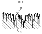
この処理時間を適正化することにより、図7に示すように、アルミニウム製の軸62の表面には、1μm以下の微細な針状或いは花弁状の凸部20が形成され、1μm以上、望ましくは約5μmのピット状の凹部21が形成された。
By optimizing this processing time, as shown in FIG. 7, a fine needle-like or petal-like
このとき、ひずみ度Skは−1.2であった。この表面をX線回折装置により分析すると、水和アルミニウムであるベーマイト(Al2O3・H2O)やバイヤライトが形成されていた。また、図8に示すように、ピット状の凹部21の周囲にも水和アルミニウム被膜22が形成されていた。ひずみ度が負の場合、表面粗さが平滑であることを示している。ひずみ度Skが正であると表面が粗く、相手材を摩耗させやすくなる。
At this time, the degree of distortion Sk was -1.2. When this surface was analyzed by an X-ray diffractometer, boehmite (Al 2 O 3 .H 2 O) and bayerite, which are hydrated aluminum, were formed. Further, as shown in FIG. 8, a
この水和アルミニウム22を形成したアルミニウム製の軸62を加熱炉(図示せず)内に入れ、450℃に加熱した。加熱後もひずみ度に変化はなく、針状あるいは花弁状の微細な凸部20やピット状の凹部21も形成されたままであるが、表面の結晶状態は、X線回折装置による分析ではAl2O3であり、水和物の水分がなくなっていた。
The
この時の加熱温度は、水和物の水分がなくなる温度にすればよく、水の沸点である100℃以上であればよい(加熱温度の上限は、アルミニウムの融点が660℃であることから、600℃が望ましい)。望ましくは熱重量分析装置等で、水和物の水分がなくなる温度を測定し、その温度以上にすればよい。 The heating temperature at this time may be a temperature at which the water content of the hydrate disappears, and may be 100 ° C. or higher which is the boiling point of water (the upper limit of the heating temperature is that the melting point of aluminum is 660 ° C. 600 ° C. is desirable). Desirably, the temperature at which the water content of the hydrate disappears is measured with a thermogravimetric analyzer or the like, and the temperature may be raised to that temperature or higher.
図1には、試験部の周囲に保護カバー63を貫通した連通穴64を設け、それより吐出される気体の流れ65を示す。
In FIG. 1, a
該図に示すように、摺動部付近に向けて連通穴64から窒素ガスを10L/min供給した。軸の回転速度は1〜3mm/sとした。その結果、軸62の表面に軸受60のPTFEが一様に移着しており、面圧5MPaの不活性ガス中でも摺動部に異常摩耗は見られなかった。
As shown in the figure, nitrogen gas was supplied at 10 L / min from the
即ち、水和アルミニウム皮膜22から水和物の水分をなくした酸化アルミニウム被膜を形成したアルミニウムは、耐摩耗材としても効果があると言える。
That is, it can be said that the aluminum in which the aluminum oxide film from which the hydrated water has been removed is formed from the
なお、上述した例は、軸62にアルミニウムを用いて説明したが、アルミニウム合金であっても同様である。
[実施例2]
次に、図2示すピンオンディスク型の試験部を用いて実施例2を説明する。
In the example described above, aluminum is used for the
[Example 2]
Next, Example 2 will be described using a pin-on-disk type test section shown in FIG.
該図に示す如く、実施例1と同様にして水和アルミニウム皮膜を形成したアルミニウムを加熱炉(図示せず)により450℃で加熱した後冷却し、ディスク状のディスク試験片33とし、また、PTFEを主成分とするウェアリング材を、直径8mmのピン状試験片31として試験装置30に設置した。ディスク試験片33のひずみ度は−1.3であった。試験条件は、ディスクの回転速度を1m/sとして、摺動部にカバー32を介して押し付け荷重34を加えた。
As shown in the figure, aluminum having a hydrated aluminum film formed in the same manner as in Example 1 was heated at 450 ° C. in a heating furnace (not shown) and then cooled to form a disk-shaped
その結果、面圧が9MPaにおいても,ディスク試験片33及びピン試験片31とも異常摩耗は見られなかった。即ち、水和アルミニウム皮膜から水和物の水分をなくした酸化アルミニウム被膜を形成したアルミニウムは、このような摺動形態でも耐摩耗材としても効果があると言える。なお、上述した例は、アルミニウム合金であっても同様である。
[実施例3]
次に、実施例3について説明する。本実施例では、図3に示すように、実施例2の装置を用いて摺動部付近に連通穴36を設け、そこから窒素ガス37を10L/min供給した。その他は先の実施例2と同様である。
As a result, even when the surface pressure was 9 MPa, neither the
[Example 3]
Next, Example 3 will be described. In this example, as shown in FIG. 3, the
その結果、面圧が9MPaの不活性ガス中においてもディスク試験片33及びピン試験片31とも異常摩耗が見られなかった。
As a result, neither the
このようにアルミニウムに水和アルミニウム皮膜を形成後加熱すると、空気中だけでなく窒素ガス中でも耐摩耗性に優れることがわかる。
[実施例4]
本実施例は、実施例2のアルミニウム製のディスク試験片33に、実施例1と同様の方法で水和アルミニウムを処理して加熱を行い、ピン試験片31にPEEK樹脂を用いたものである。この組合せで摺動試験を行っても、摺動部に顕著な摩耗は見られなかった。
[実施例5]
本実施例は、実施例2のアルミニウム製のディスク試験片33に実施例1と同様の方法で水和アルミニウムを処理して加熱を行い、ピン試験片31にポリアセタール樹脂を用いた。この組合せで摺動試験を行っても、摺動部に顕著な摩耗は見られなかった。
[実施例6]
次に、本発明の実施例6として、アルミニウムの耐摩耗材をパッファ型ガス遮断器に適用した例を、図4及び図5を用いて説明する。
Thus, when it heats after forming a hydrated aluminum film in aluminum, it turns out that it is excellent in abrasion resistance not only in air but in nitrogen gas.
[Example 4]
In this example, the aluminum
[Example 5]
In this example, the aluminum
[Example 6]
Next, as Example 6 of the present invention, an example in which an aluminum wear-resistant material is applied to a puffer type gas circuit breaker will be described with reference to FIGS.
図4は、本発明の実施例6を示すパッファ型ガス遮断器であり、電流投入状態を示すものである。
FIG. 4 is a puffer type gas circuit
該図に示す如く、本実施例のパッファ型ガス遮断器は、固定側アーク接触子1と、この固定側アーク接触子1の外部に配置された固定側主接触子2とにより固定側通電部を構成し、この固定側通電部と接する可動側通電部は、可動側アーク接触子5と、その可動側アーク接触子5の外側に配置された可動側主接触子4で構成され、パッファシリンダ6に固定されている。
As shown in the figure, the puffer type gas circuit breaker of the present embodiment includes a fixed-side energization section by a fixed-
パッファシリンダ6の中央部にはシリンダシャフト7が設置され、このシリンダシャフト7は、リンク18を介して絶縁操作ロッド14に接続され、この絶縁操作ロッド14を操作器(図示せず)により駆動することで、固定側通電部と可動側通電部との閉極又は開極の動作を行う。また、パッファシリンダ6の外周部には外部集電子8が配置され、この外部集電子8は、絶縁筒(図示せず)により支持される可動側主回路導体(図示せず)に接続される。
A
一方、パッファシリンダ6の内部にはピストン10が嵌合されており、パッファシリンダ6の内面とシリンダシャフト7の外面及びピストン10で囲まれて、消弧性気体を圧縮するためのパッファ室13が形成されている。パッファシリンダ6はアルミニウム製であり、ピストン10の外周部には、径の異なるウェアリング11及び12がそれぞれ設けられており、ピストン10の移動に伴い、ウェアリング11及び12を介して、ピストン10とパッファシリンダ6の内面及びピストン10とシリンダシャフト7の内面が摺動する。
On the other hand, a
図5は、図4の電流投入状態から電流遮断動作を行った時の状態を示している。図5に示す電流遮断動作の際には、パッファシリンダ6が図5の右方向に移動し、それに伴い、固定側アーク接触子1と可動側アーク接触子5が離れると共に、ピストン10が移動してパッファ室13の容積が小さくなるように圧縮されることで、絶縁ノズル3から消弧性気体が、固定側アーク接触子1と可動側アーク接触子5間に発生するアークに吹付けられるため、アークが消滅するものである。
FIG. 5 shows a state when the current cut-off operation is performed from the current input state of FIG. In the current interruption operation shown in FIG. 5, the
このように構成される本実施例のパッファ型ガス遮断器では、パッファシリンダ6のウェアリング11及び12と摺動する部分よりも広い範囲(符号15で示す)に、水和アルミニウムを形成する処理を行った。即ち、アルミニウム製のパッファシリンダ6のピストン10が摺動する内壁面である表面に化成処理によって水和酸化物被膜である水和アルミニウムを形成し、その水和アルミニウム表面に凸部20を有し、かつ、ピット状の凹部21を形成する処理を行った。
In the puffer type gas circuit breaker of the present embodiment configured as described above, a process of forming hydrated aluminum in a wider range (shown by reference numeral 15) than a portion sliding with the wear rings 11 and 12 of the
この水和アルミニウムを形成する処理(化成処理)方法として、機械加工後、脱脂洗浄を行ったパッファシリンダ6を、95℃以上に加熱した純水に所定の時間浸漬した。
As a treatment (chemical conversion treatment) method for forming this hydrated aluminum, the
この水和アルミニウムを形成したパッファシリンダ6を乾燥機(図示せず)に入れ、450℃に加熱し、水和アルミニウムから水和物である水和物の水分を除去した。加熱後のパッファシリンダ6の内壁面である表面は、加熱前と同様に1μm以下の微細な針状あるいは花弁状の凸部20が形成され、1μm以上、望ましくは約5μmのピット状の凹部21が確認された。この表面をX線回折装置により分析すると、酸化アルミニウム(Al2O3)となっていた。
The
図9に、水和アルミニウムを形成したパッファシリンダ6を450℃に加熱することで、水和アルミニウムから水和物に水分が除去されることを説明するための実験結果を示す。図9は、横軸に温度(℃)を、縦軸に重量(%)を取り、アルミニウム製のパッファシリンダ6に化成処理を行って水和アルミニウムを形成し、その後、加熱しつつ重量変化(%)を測定したものである。
FIG. 9 shows experimental results for explaining that moisture is removed from hydrated aluminum to hydrate by heating
該図に示す如く、450℃付近で重量変化がなくなっているため、水和アルミニウムから水和物の水分がなくなっていることが理解される。 As shown in the figure, it is understood that the water content of the hydrate is lost from the hydrated aluminum because there is no weight change at around 450 ° C.
なお、本実施例では、アルミニウム製のパッファシリンダ6を450℃で加熱した例について説明したが、実施例1で説明したように、加熱温度は、100〜600℃であれば良いことは言うまでもない。
In the present embodiment, the example in which the
このような本実施例によれば、低コストで、かつ、アルミニウム製のパッファシリンダ6に微細な凹凸或いは微細な凹凸と、それよりも大きい凹凸から成る被膜を形成することで、ウェアリング材11及び12の移着を促進させ、アルミニウムの摩耗粉を抑制できるので、耐摩耗性が向上する。
According to the present embodiment, the
なお、上述した例は、パッファシリンダ6にアルミニウムを用いて説明したが、アルミニウム合金であっても同様な効果を得ることができる(以下の実施例でも同様である)。
[実施例7]
図6に、本発明のパッファ型ガス遮断器の実施例7を示す。該図に示す本実施例では、パッファシリンダ6の全体17に水和アルミニウムを形成し、その後、加熱を行ったものである。処理条件は実施例6と同様である。
In the example described above, aluminum is used for the
[Example 7]
FIG. 6 shows a seventh embodiment of the puffer-type gas circuit breaker according to the present invention. In this embodiment shown in the figure, hydrated aluminum is formed on the
このような本実施例によれば、実施例6と同様な効果を得ることができる。
[実施例8]
本実施例では、実施例6の純水に少量のエタノールアミンを加えた水溶液を用いて、パッファシリンダ6に水和アルミニウムを形成したものである。
According to such a present Example, the effect similar to Example 6 can be acquired.
[Example 8]
In this embodiment, hydrated aluminum is formed on the
このような本実施例によれば、実施例6と同様な効果を得ることができることは勿論、本実施例の水溶液を使うことで、パッファシリンダ6を95℃以上にした水溶液中に浸漬する時間を短縮することができる。水和アルミニウム被膜形成後、実施例6と同様に、パッファシリンダ6を加熱して水和物の水分を除去している。
According to the present embodiment, the same effect as that of the sixth embodiment can be obtained. Of course, by using the aqueous solution of the present embodiment, the time for immersing the
なお、本実施例ではアンモニアを使用したが、この他に水溶液をアルカリ性にする液体や固体を使用しても構わない。
[実施例9]
本実施例では、実施例6と同様に、パッファシリンダ6に水和アルミニウムを形成する処理を行い、実施例6よりも処理時間を長くしたものである。この時のひずみ度Skは−0.3、ピット状の凹部21は2〜5μmであり、実施例6と同様にベーマイトやバイヤライトが形成されていた。このパッファシリンダを、実施例6と同様に、加熱して水和物の水分を除去している。加熱後のパッファシリンダ6の内壁面の表面には、加熱前と同様に微細な針状あるいは花弁状の凹凸や、ピット状の凹部21が形成されていた。
In this embodiment, ammonia is used, but in addition to this, a liquid or solid that makes the aqueous solution alkaline may be used.
[Example 9]
In the present embodiment, similarly to the sixth embodiment, a process for forming hydrated aluminum in the
このような本実施例によれば、実施例6と同様な効果を得ることができる。
[比較例1]
比較例1として、実施例6よりも95℃以上に加熱した純水への侵漬処理時間を短くして、水和アルミニウムを形成したパッファシリンダを450℃で加熱したものとした。この時のひずみ度Skは−0.9である。
[比較例2]
比較例2として、未処理のアルミニウムを用いたものとした。この時のひずみ度Skは−0.03である。
According to such a present Example, the effect similar to Example 6 can be acquired.
[Comparative Example 1]
As Comparative Example 1, the puffer cylinder formed with hydrated aluminum was heated at 450 ° C. with a shorter immersion time in pure water heated to 95 ° C. or higher than that in Example 6. The degree of distortion Sk at this time is −0.9.
[Comparative Example 2]
As Comparative Example 2, untreated aluminum was used. The degree of distortion Sk at this time is -0.03.
実施例6乃至9及び比較例1及び2を、それぞれガス遮断器に組み込み摺動試験を行った。相手材はPTFEを主成分とし、ガラス等の充填材を含まないウェアリングを用いた。この結果を表1に示す。 Examples 6 to 9 and Comparative Examples 1 and 2 were each incorporated in a gas circuit breaker and subjected to a sliding test. The mating material used was a wear ring containing PTFE as a main component and containing no filler such as glass. The results are shown in Table 1.

表1から明らかな如く、実施例6乃至8では、パッファシリンダ6とウェアリング11及び12には、共に異常摩耗は見られなかった。実施例9では、パッファシリンダ6に異常摩耗はないが、ウェアリング11及び12が実施例6に比べやや摩耗していた。これは、ひずみ度が小さくなったことで、表面の平滑性が実施例6よりも粗くなっているためである。
As is apparent from Table 1, in Examples 6 to 8, neither the
各実施例とも、摺動部を観察すると、表面の微細な凹凸やピット状の深い凹み内にPTFEが移着していることが確認された。水滴を滴下してみると接触角は100〜110度を示したことからも、PTFEの移着が確認できる。表面の微細な凹凸やピット状の凹みがウェアリング11及び12を初期に摩耗させ、その摩耗粉を保持することで、アルミニウム製のパッファシリンダ6の耐摩耗性を高めている。
In each example, when the sliding portion was observed, it was confirmed that PTFE had been transferred into the fine irregularities on the surface and deep pits. When a drop of water was dropped, the contact angle showed 100 to 110 degrees, so that the transfer of PTFE could be confirmed. Fine wear on the surface and pit-shaped dents wear the wear rings 11 and 12 in the initial stage and retain the wear powder, thereby improving the wear resistance of the
比較例1では処理時間が短く、十分な水和アルミニウムの被膜が形成されなかったため、加熱後の表面も酸化アルミニウムの被膜が不十分であり、パッファシリンダが摩耗し、アルミニウムの摩耗粉によりウェアリングも摩耗していた。 In Comparative Example 1, the treatment time was short and sufficient hydrated aluminum coating was not formed. Therefore, the surface after heating was insufficient with aluminum oxide coating, the puffer cylinder was worn, and the wear ring was worn by aluminum wear powder. Was also worn.
比較例2の未処理のアルミニウムも、比較例1以上に摩耗していた。ウェアリングも摩耗していた。 The untreated aluminum of Comparative Example 2 was also worn more than Comparative Example 1. The wear ring was also worn.
このように、アルミニウムの表面に水和アルミニウムを形成し加熱して、表面の微細な凹凸やピット状の凹部形状は水和アルミニウムのそのままに、水和物の水分のみをなくすと、未処理に比べパッファシリンダ6の耐摩耗性が向上し、本発明のパッファ型ガス遮断器の動作条件では、アルマイトや無電解Ni−Pめっきと同等の耐摩耗性を示しており、アルマイト等に比べ簡易な設備で被膜の形成処理や廃液処理ができる。
In this way, when hydrated aluminum is formed on the surface of aluminum and heated, the fine irregularities on the surface and the pit-like concave shape remain in the hydrated aluminum, and only the water of the hydrate is removed. The wear resistance of the
なお、本発明は上記した実施例に限定されるものではなく、様々な変形例が含まれる。例えば、上記した実施例は本発明を分かり易く説明するために詳細に説明したものであり、必ずしも説明した全ての構成を備えるものに限定されるものではない。また、ある実施例の構成の一部を他の実施例の構成に置き換えることが可能であり、また、ある実施例の構成に他の実施例の構成を加えることも可能である。また、各実施例の構成の一部について、他の構成の追加・削除・置換をすることが可能である。 In addition, this invention is not limited to an above-described Example, Various modifications are included. For example, the above-described embodiments have been described in detail for easy understanding of the present invention, and are not necessarily limited to those having all the configurations described. Further, a part of the configuration of one embodiment can be replaced with the configuration of another embodiment, and the configuration of another embodiment can be added to the configuration of one embodiment. Further, it is possible to add, delete, and replace other configurations for a part of the configuration of each embodiment.
1…固定側アーク接触子、2…固定側主接触子、3…絶縁ノズル、4…可動側主接触子、5…可動側アーク接触子、6…パッファシリンダ、7…シリンダシャフト、8…外部集電子、10…ピストン、11、12…ウェアリング、13…パッファ室、14…絶縁操作ロッド、17…パッファシリンダの全体、18…リンク、20…凸部、21…凹部、22…水和アルミニウム被膜、30…試験装置、31…ピン状試験片、32…カバー、33…ディスク試験片、34…押し付け荷重、36、64…連通穴、37…窒素ガス、60…軸受、61…ケーシング、62…軸、63…保護カバー、65…気体の流れ。
DESCRIPTION OF
Claims (10)
前記アルミニウム又はその合金の表面に化成処理によって形成されるアルミニウム又はその合金の水和酸化物被膜に、その表面に凸部を有し、かつ、ピット状の凹部が形成されていると共に、前記アルミニウム又はその合金の表面に形成される前記水和酸化物被膜の水和物の水分が除去され、
前記アルミニウム又はその合金は、該アルミニウム又はその合金の表面にひずみ度の値が負であり、かつ、ピット状の凹部の深さが1μm以上である化成処理が施された前記アルミニウム又はその合金の表面粗さを有することを特徴とする耐摩耗材。 A wear-resistant material made of aluminum or an alloy thereof,
The aluminum or its alloy hydrated oxide film formed on the surface of the aluminum or its alloy has a convex portion on its surface and a pit-shaped concave portion, and the aluminum Or the moisture of the hydrated oxide film formed on the surface of the alloy is removed ,
The aluminum or its alloy has a negative value of the degree of strain on the surface of the aluminum or its alloy, and the aluminum or its alloy subjected to a chemical conversion treatment in which the depth of the pit-shaped recess is 1 μm or more. A wear-resistant material characterized by having a surface roughness .
前記アルミニウム又はその合金製のパッファシリンダの少なくとも前記ピストンが摺動する内壁の表面に化成処理によって形成されるアルミニウム又はその合金の水和酸化物被膜に、その表面に凸部を有し、かつ、ピット状の凹部が形成されていると共に、前記アルミニウム又はその合金の表面に形成される前記水和酸化物被膜の水和物の水分が除去されていることを特徴とするパッファシリンダ。 It is connected to a movable side arc contact that contacts and separates from the fixed side arc contact, and a piston is fitted inside, while the piston slides on the inner wall surface to suck or blow off the arc extinguishing gas. A moving puffer cylinder made of aluminum or its alloy,
The aluminum or its alloy hydrated oxide film formed by chemical conversion treatment on the surface of the inner wall on which at least the piston slides of the aluminum or alloy puffer cylinder has a convex portion on its surface, and A puffer cylinder characterized in that a pit-shaped recess is formed and moisture of the hydrated oxide film formed on the surface of the aluminum or its alloy is removed.
前記パッファシリンダは、該パッファシリンダの内壁面にひずみ度の値が負であり、かつ、ピット状の凹部深さが1μm以上である化成処理が施された前記アルミニウム又はその合金の表面粗さを有することを特徴とするパッファシリンダ。 The puffer cylinder according to claim 2 ,
The puffer cylinder has a surface roughness of the aluminum or an alloy thereof subjected to a chemical conversion treatment in which the inner wall surface of the puffer cylinder has a negative strain value and a pit-like recess depth is 1 μm or more. A puffer cylinder characterized by comprising:
前記ピストンの外周部にウェアリングが設置され、該ウェアリングが前記パッファシリンダの内壁面を摺動することを特徴とするパッファシリンダ。 The puffer cylinder according to claim 2 or 3 ,
A puffer cylinder, characterized in that a wear ring is installed on an outer peripheral portion of the piston, and the wear ring slides on an inner wall surface of the puffer cylinder.
前記パッファシリンダの全体に、前記化成処理によって形成されるアルミニウム又はその合金の表面の前記水和酸化物被膜から水和物の水分が除去された酸化物被膜が形成されていることを特徴とするパッファシリンダ。 The puffer cylinder according to any one of claims 2 to 4 ,
An oxide film in which moisture of hydrate is removed from the hydrated oxide film on the surface of aluminum or an alloy thereof formed by the chemical conversion treatment is formed on the entire puffer cylinder. Puffer cylinder.
前記パッファシリンダは、請求項2乃至5のいずれか1項に記載のパッファシリンダであることを特徴とするパッフア型ガス遮断器。 In a container filled with arc extinguishing gas, a stationary contact, a movable contact contacting and separating from the stationary contact, a puffer cylinder made of aluminum or its alloy connected to the movable contact, and the puffer cylinder A piston that sucks or ejects the arc-extinguishing gas, and moves the arc-extinguishing gas ejected as the piston moves with the fixed contact. A puffer type gas circuit breaker that blows off the arc generated by the separation of the child and extinguishes,
The puffer type gas circuit breaker according to any one of claims 2 to 5 , wherein the puffer cylinder is the puffer cylinder according to any one of claims 2 to 5 .
前記アルミニウム又はその合金の表面に化成処理によって形成されるアルミニウム又はその合金の水和酸化物被膜に、その表面に凸部を有し、かつ、ピット状の凹部が形成され、その後、前記アルミニウム又はその合金の表面に形成される水和酸化物被膜を加熱して該水和酸化物被膜から水和物の水分を除去することを特徴とする耐摩耗材の製作方法。 In producing a wear-resistant material made of aluminum or an alloy thereof,
The aluminum or aluminum or hydrated oxide coating of the alloy is formed by chemical conversion treatment on the surface of the alloy, has a convex portion on the surface thereof, and pits shaped recess is formed, then the aluminum or A method for producing a wear-resistant material, comprising heating a hydrated oxide film formed on the surface of the alloy to remove hydrated water from the hydrated oxide film.
前記アルミニウム又はその合金の表面に形成される前記水和酸化物被膜を加熱する温度は、100〜600℃であることを特徴とする耐摩耗材の製作方法。 In the manufacturing method of the wear-resistant material according to claim 7 ,
A method for producing a wear-resistant material, wherein a temperature for heating the hydrated oxide film formed on the surface of the aluminum or an alloy thereof is 100 to 600 ° C.
前記アルミニウム又はその合金製のパッファシリンダの少なくとも前記ピストンが摺動する内壁の表面に化成処理によって形成されるアルミニウム又はその合金の水和酸化物被膜に、その表面に凸部を有し、かつ、ピット状の凹部が形成され、その後、前記アルミニウム又はその合金の表面に形成される前記水和酸化物被膜を加熱して該水和酸化物被膜から水和物の水分を除去することを特徴とするパッファシリンダの製作方法。 It is connected to the movable arc contact that is in contact with and away from the fixed arc contact, and the piston is fitted inside, while the piston slides on the inner wall surface to suck or jet arc extinguishing gas. In making a moving puffer cylinder made of aluminum or its alloy,
The aluminum or its alloy hydrated oxide film formed by chemical conversion treatment on the surface of the inner wall on which at least the piston slides of the aluminum or alloy puffer cylinder has a convex portion on its surface, and A pit-shaped recess is formed, and then the hydrated oxide film formed on the surface of the aluminum or its alloy is heated to remove moisture from the hydrated oxide film. How to make a puffer cylinder.
前記アルミニウム又はその合金の表面に形成される前記水和酸化物被膜を加熱する温度は、100〜600℃であることを特徴とするパッファシリンダの製作方法。 In the manufacturing method of the puffer cylinder according to claim 9 ,
A method for manufacturing a puffer cylinder, wherein a temperature for heating the hydrated oxide film formed on a surface of the aluminum or an alloy thereof is 100 to 600 ° C.
Priority Applications (3)
| Application Number | Priority Date | Filing Date | Title |
|---|---|---|---|
| JP2013178973A JP6077422B2 (en) | 2013-08-30 | 2013-08-30 | Wear-resistant material and method for manufacturing the same, puffer cylinder, method for manufacturing the same and puffer-type gas circuit breaker |
| CN201410336198.0A CN104425179A (en) | 2013-08-30 | 2014-07-15 | Wear-Resistant Material, Method for Producing the Same, Puffer Cylinder and Puffer-Type Gas Circuit Breaker |
| US14/335,465 US9653239B2 (en) | 2013-08-30 | 2014-07-18 | Wear-resistant material, method for producing the same, puffer cylinder and puffer-type gas circuit breaker |
Applications Claiming Priority (1)
| Application Number | Priority Date | Filing Date | Title |
|---|---|---|---|
| JP2013178973A JP6077422B2 (en) | 2013-08-30 | 2013-08-30 | Wear-resistant material and method for manufacturing the same, puffer cylinder, method for manufacturing the same and puffer-type gas circuit breaker |
Publications (3)
| Publication Number | Publication Date |
|---|---|
| JP2015048489A JP2015048489A (en) | 2015-03-16 |
| JP2015048489A5 JP2015048489A5 (en) | 2016-02-25 |
| JP6077422B2 true JP6077422B2 (en) | 2017-02-08 |
Family
ID=52581686
Family Applications (1)
| Application Number | Title | Priority Date | Filing Date |
|---|---|---|---|
| JP2013178973A Active JP6077422B2 (en) | 2013-08-30 | 2013-08-30 | Wear-resistant material and method for manufacturing the same, puffer cylinder, method for manufacturing the same and puffer-type gas circuit breaker |
Country Status (3)
| Country | Link |
|---|---|
| US (1) | US9653239B2 (en) |
| JP (1) | JP6077422B2 (en) |
| CN (1) | CN104425179A (en) |
Families Citing this family (3)
| Publication number | Priority date | Publication date | Assignee | Title |
|---|---|---|---|---|
| FR3001575B1 (en) * | 2013-01-29 | 2015-03-20 | Alstom Technology Ltd | CIRCUIT BREAKER WITH MEANS REDUCING THE ARC SWITCH BETWEEN PERMANENT CONTACTS |
| JP6053162B2 (en) | 2013-06-18 | 2017-01-18 | 株式会社日立製作所 | Manufacturing method of puffer cylinder |
| WO2019150550A1 (en) * | 2018-02-02 | 2019-08-08 | 株式会社東芝 | Gas circuit breaker |
Family Cites Families (16)
| Publication number | Priority date | Publication date | Assignee | Title |
|---|---|---|---|---|
| US3704176A (en) * | 1965-10-09 | 1972-11-28 | Sumitomo Electric Industries | Method of resin coating a metal and resin-coated metal product thereof |
| US3506799A (en) * | 1967-06-23 | 1970-04-14 | Westinghouse Electric Corp | Circuit breaker with improved venting means and arc extinguishing structure |
| JPS51106646A (en) * | 1975-03-17 | 1976-09-21 | Matsushita Electric Ind Co Ltd | ARUMAITOHIMAKUNIOKERU HASONBUNOSHUFUKUHOHO |
| JPS5834925B2 (en) * | 1976-04-02 | 1983-07-29 | 昭和アルミニウム株式会社 | Manufacturing method of aluminum foil for electrolytic capacitors |
| JPS5834926B2 (en) * | 1976-07-30 | 1983-07-29 | 昭和アルミニウム株式会社 | Manufacturing method of aluminum foil for electrolytic capacitors |
| JPS63184223A (en) * | 1987-01-26 | 1988-07-29 | 三菱電機株式会社 | Breaker |
| JPH0299172A (en) * | 1988-10-05 | 1990-04-11 | Mitsubishi Heavy Ind Ltd | Coating method of fluororesin |
| JP2003013253A (en) * | 2001-07-04 | 2003-01-15 | Kobe Steel Ltd | Aluminum-alloy structural material superior in adhesiveness to coating and method for evaluating adhesiveness to coating of aluminum-alloy structural material |
| JP2004277784A (en) * | 2003-03-14 | 2004-10-07 | Hitachi Ltd | Aluminum of high corrosion resistance and wear resistance, and surface treatment method therefor |
| JP5201787B2 (en) * | 2005-10-07 | 2013-06-05 | 住友軽金属工業株式会社 | Aluminum alloy plate for forming, method for producing the same, and method for processing aluminum alloy plate for forming |
| JP4660407B2 (en) | 2006-03-27 | 2011-03-30 | 株式会社東芝 | Gas insulated switch |
| JP4960139B2 (en) * | 2007-04-26 | 2012-06-27 | 株式会社東芝 | Gas circuit breaker and manufacturing method thereof |
| JP4902439B2 (en) | 2007-06-25 | 2012-03-21 | 株式会社日本Aeパワーシステムズ | Puffer type gas circuit breaker |
| US20090311577A1 (en) * | 2008-06-12 | 2009-12-17 | Hitachi Cable, Ltd. | Corrosion-resistant material and manufacturing method of the same |
| JP2011052292A (en) * | 2009-09-03 | 2011-03-17 | Shingijutsu Kenkyusho:Kk | Aluminum alloy article, aluminum alloy member, and method for producing the same |
| JP6053162B2 (en) * | 2013-06-18 | 2017-01-18 | 株式会社日立製作所 | Manufacturing method of puffer cylinder |
-
2013
- 2013-08-30 JP JP2013178973A patent/JP6077422B2/en active Active
-
2014
- 2014-07-15 CN CN201410336198.0A patent/CN104425179A/en active Pending
- 2014-07-18 US US14/335,465 patent/US9653239B2/en active Active
Also Published As
| Publication number | Publication date |
|---|---|
| US9653239B2 (en) | 2017-05-16 |
| JP2015048489A (en) | 2015-03-16 |
| US20150060408A1 (en) | 2015-03-05 |
| CN104425179A (en) | 2015-03-18 |
Similar Documents
| Publication | Publication Date | Title |
|---|---|---|
| JP6077422B2 (en) | Wear-resistant material and method for manufacturing the same, puffer cylinder, method for manufacturing the same and puffer-type gas circuit breaker | |
| JP6053162B2 (en) | Manufacturing method of puffer cylinder | |
| CN101048837A (en) | Switching chamber and heavy-duty circuit breaker | |
| JP2013503764A (en) | Method of forming an article from a non-melt processable polymer and article formed thereby | |
| CN108220908A (en) | A kind of method that frictional interface is formed in situ graphene and onion realizes superslide | |
| US10128071B2 (en) | Abrasion resistant material, puffer cylinder, and puffer type gas circuit breaker | |
| JP6310906B2 (en) | Carbon material for bearing and sliding member made of carbon material for bearing | |
| JP5393967B2 (en) | Sliding material and fluid compression machine | |
| CN207489746U (en) | Vacuum interrupter | |
| Ravikiran et al. | Water-lubricated sliding of Al2O3 against steel | |
| JP2020068080A (en) | Puffer cylinder and puffer gas breaker | |
| CN105470019B (en) | A kind of high-voltage circuitbreaker quenching nozzle densification sintering method and high-voltage circuitbreaker quenching nozzle | |
| JP6523595B2 (en) | Dry gas compressor | |
| JP2017136639A (en) | Electrode for electric resistance-welding | |
| JP4429209B2 (en) | Gas insulated switchgear | |
| CN106402217A (en) | Nanoscale compound wear-resisting brake pad | |
| JP5275421B2 (en) | Reciprocating compressor | |
| JP5683986B2 (en) | Gas circuit breaker | |
| CN107502939B (en) | Wear-resistant bearing rolling body | |
| CN105221572A (en) | Sintered metal bearing and linear actuators | |
| WO2019130566A1 (en) | Sintered bearing and manufacturing method therefor | |
| JP2009085233A (en) | Method for manufacturing plain bearing | |
| JP2016145602A (en) | Hydrogen feed system | |
| CN205503769U (en) | Bearing body that high pressure column type circuit breaker was used | |
| CN104806316A (en) | Wear-resistant valve rocker arm |
Legal Events
| Date | Code | Title | Description |
|---|---|---|---|
| A521 | Written amendment |
Free format text: JAPANESE INTERMEDIATE CODE: A523 Effective date: 20160107 |
|
| A621 | Written request for application examination |
Free format text: JAPANESE INTERMEDIATE CODE: A621 Effective date: 20160107 |
|
| A977 | Report on retrieval |
Free format text: JAPANESE INTERMEDIATE CODE: A971007 Effective date: 20161111 |
|
| A131 | Notification of reasons for refusal |
Free format text: JAPANESE INTERMEDIATE CODE: A131 Effective date: 20161122 |
|
| A521 | Written amendment |
Free format text: JAPANESE INTERMEDIATE CODE: A523 Effective date: 20161202 |
|
| TRDD | Decision of grant or rejection written | ||
| A01 | Written decision to grant a patent or to grant a registration (utility model) |
Free format text: JAPANESE INTERMEDIATE CODE: A01 Effective date: 20170110 |
|
| A61 | First payment of annual fees (during grant procedure) |
Free format text: JAPANESE INTERMEDIATE CODE: A61 Effective date: 20170112 |
|
| R150 | Certificate of patent or registration of utility model |
Ref document number: 6077422 Country of ref document: JP Free format text: JAPANESE INTERMEDIATE CODE: R150 |