JP6076852B2 - Camera system, control method thereof and control program thereof - Google Patents

Camera system, control method thereof and control program thereof Download PDF

Info

Publication number
JP6076852B2
JP6076852B2 JP2013145584A JP2013145584A JP6076852B2 JP 6076852 B2 JP6076852 B2 JP 6076852B2 JP 2013145584 A JP2013145584 A JP 2013145584A JP 2013145584 A JP2013145584 A JP 2013145584A JP 6076852 B2 JP6076852 B2 JP 6076852B2
Authority
JP
Japan
Prior art keywords
map
unit
area
camera system
image
Prior art date
Legal status (The legal status is an assumption and is not a legal conclusion. Google has not performed a legal analysis and makes no representation as to the accuracy of the status listed.)
Active
Application number
JP2013145584A
Other languages
Japanese (ja)
Other versions
JP2015019270A (en
JP2015019270A5 (en
Inventor
宣隆 木村
宣隆 木村
吉田 明
明 吉田
俊宏 鯨井
俊宏 鯨井
Current Assignee (The listed assignees may be inaccurate. Google has not performed a legal analysis and makes no representation or warranty as to the accuracy of the list.)
Hitachi Industry and Control Solutions Co Ltd
Original Assignee
Hitachi Industry and Control Solutions Co Ltd
Priority date (The priority date is an assumption and is not a legal conclusion. Google has not performed a legal analysis and makes no representation as to the accuracy of the date listed.)
Filing date
Publication date
Application filed by Hitachi Industry and Control Solutions Co Ltd filed Critical Hitachi Industry and Control Solutions Co Ltd
Priority to JP2013145584A priority Critical patent/JP6076852B2/en
Publication of JP2015019270A publication Critical patent/JP2015019270A/en
Publication of JP2015019270A5 publication Critical patent/JP2015019270A5/ja
Application granted granted Critical
Publication of JP6076852B2 publication Critical patent/JP6076852B2/en
Active legal-status Critical Current
Anticipated expiration legal-status Critical

Links

Images

Description

本発明は、対象物を漏れなく撮影するためのカメラシステム、その制御方法およびその制御プログラムに関するものである。   The present invention relates to a camera system for photographing an object without omission, a control method thereof, and a control program thereof.

従来から、住宅、プラント、トンネル、橋梁などの構造物は、時間の経過と共に亀裂や腐食などが発生することから、定期的な点検が広く行われている。最も基本的な点検は構造物の表面を目視確認することであるが、現場点検作業後のデスクワーク等で現場の状態を再確認したいというニーズもあることから、点検対象をカメラで撮影し画像を保存しておくのが一般的である。また、作業員自らが現場を巡回することはコストがかかり、特に、住宅の床下や天井裏、原子力プラントなどの極限環境下、橋梁の裏側などを点検する際に、その空間に入る、あるいは点検可能な位置まで移動することは作業者へ大きな負担をかけることになる。このことから、点検対象を撮影可能な位置へカメラを運び入れ、作業者がそのカメラを遠隔操作することで点検対象を撮影し、その画像を作業者が確認することで点検を行うシステムもある。   Conventionally, periodic inspections have been widely performed on structures such as houses, plants, tunnels, and bridges because cracks and corrosion occur over time. The most basic inspection is to visually check the surface of the structure, but there is also a need to reconfirm the state of the work site by desk work after the work site inspection work. It is common to save. In addition, it is costly for the workers themselves to go around the site, especially when they check the underfloor and ceiling of a house, the extreme environment such as a nuclear power plant, the back side of a bridge, etc. Moving to a possible position places a heavy burden on the operator. For this reason, there is also a system in which the camera is brought to a position where the inspection object can be photographed, the operator remotely operates the camera to photograph the inspection object, and the operator confirms the image. .

例えば、特許文献1には、天井裏を走行可能なロボットにカメラを搭載し、天井裏の画像を居室内で視認することが可能なシステムが記載されている。また、特許文献2には、カメラを搭載したロボットを用い、作業者の操作に加えてロボット位置姿勢あるいはカメラ姿勢を順次変更することにより、壁など点検対象の被写部位を連続的に移動して構造物の床下や天井裏の撮影漏れの防止する方法が記載されている。   For example, Patent Document 1 describes a system in which a camera is mounted on a robot that can run behind a ceiling, and an image of the ceiling can be viewed in a room. Further, in Patent Document 2, a robot equipped with a camera is used, and in addition to the operator's operation, the robot position and camera posture are sequentially changed to continuously move the object to be inspected such as a wall. The method of preventing the omission of shooting under the floor of the structure or behind the ceiling is described.

特開2011−136380号公報JP 2011-136380 A 特開2008−055569号公報JP 2008-055569 A

特許文献1や特許文献2に記載のシステムや方法では、作業員の入りにくい場所においても点検対象を撮影することにより点検できると共に画像を残しておくことにより再確認が可能である。   With the systems and methods described in Patent Document 1 and Patent Document 2, inspection can be performed by photographing an inspection object even in a place where it is difficult for an operator to enter, and reconfirmation can be performed by leaving an image.

ところが、カメラを利用した点検では、点検対象となる部位を漏らすことなく撮影することが重要である。これに対して、特許文献1に記載のシステムでは撮影が作業者の遠隔操縦に任されており、撮影漏れが発生するか否かは作業者の個人的技量に依存してしまう。   However, in an inspection using a camera, it is important to take an image without leaking a part to be inspected. On the other hand, in the system described in Patent Document 1, shooting is left to the operator's remote control, and whether or not shooting failure occurs depends on the operator's personal skill.

また、特許文献2に記載の方法では予め設定された点検シーケンスにしたがって単に連続的に画像を撮影するだけであるので、点検シーケンスの設定時点の想定とズレ等が発生すると点検を必要とする全ての個所を撮影できる保証は無く、作業者が遠隔操縦する場合であっても撮影漏れが発生するか否かは作業者の個人的技量に依存してしまう。   Further, in the method described in Patent Document 2, since images are simply taken continuously in accordance with a preset inspection sequence, all inspections that require inspection should be performed when an assumption, a deviation, or the like at the time of setting the inspection sequence occurs. There is no guarantee that this part can be photographed, and whether or not a photographing omission will occur depends on the operator's personal skill even when the worker is remotely controlled.

そこで、本発明は、対象となる部位を漏らすことなく撮影するよう作業者を誘導するカメラシステム、その制御方法およびその制御プログラムを提供することを目的とする。   Accordingly, an object of the present invention is to provide a camera system that guides an operator to take an image without leaking a target part, a control method thereof, and a control program thereof.

本発明は、対象物を撮影し画像を取得するカメラシステムであって、好ましくは、撮影位置と撮影姿勢を変更可能であり、前記対象物を撮影して画像へ変換する撮影部と、前記対象物を表す地図を記憶する記憶部と、前記撮影部の位置姿勢を推定し、前記撮影部の位置姿勢と前記地図とに基づき前記地図上の複数の点の中から前記撮影部に最も近い点を含む領域を被撮影領域として特定し、前記地図において前記被撮影領域に対応する箇所を図示する撮影情報含有地図を作成する演算部と、前記撮影情報含有地図を表示する表示部と、を備えたことを特徴とする。
また、本発明は、対象物を撮影し画像を取得するカメラシステムの制御方法であって、好ましくは、記憶部が前記対象物を表す地図を記憶し、撮影位置と撮影姿勢を変更可能な撮影部が前記対象物を撮影して画像へ変換し、演算部が前記撮影部の位置姿勢を推定し、前記撮影部の位置姿勢と前記地図とに基づき前記地図上の複数の点の中から前記撮影部に最も近い点を含む領域を被撮影領域として特定し、前記地図において前記被撮影領域に対応する箇所を図示する撮影情報含有地図を作成し、表示部が前記撮影情報含有地図を表示すること、を特徴とする。
また、本発明は、対象物を撮影し画像を取得するカメラシステムの制御プログラムであって、好ましくは、前記対象物を表す地図を記憶し、撮影位置と撮影姿勢に基づいて前記対象物を撮影して画像へ変換し、前記撮影部の位置姿勢を推定し、前記撮影部の位置姿勢と前記地図とに基づき前記地図上の複数の点の中から前記撮影部に最も近い点を含む領域を被撮影領域として特定し、前記地図において前記被撮影領域に対応する箇所を図示する撮影情報含有地図を作成し、前記撮影情報含有地図を表示すること、を特徴とする。
The present invention is a camera system that captures an image of an object and acquires an image, and preferably, an image capturing unit that can change an image capturing position and an image capturing posture and captures the object and converts the image into an image; A storage unit for storing a map representing an object, a position and orientation of the photographing unit, and a point closest to the photographing unit among a plurality of points on the map based on the position and orientation of the photographing unit and the map Including a calculation unit that creates a shooting information-containing map that illustrates a location corresponding to the shooting region in the map, and a display unit that displays the shooting information-containing map. It is characterized by that.
The present invention is also a control method for a camera system that captures an image of an object and acquires an image. Preferably, the storage unit stores a map representing the object, and the imaging position and orientation can be changed. The unit shoots the object and converts it into an image, the calculation unit estimates the position and orientation of the photographing unit, and based on the position and orientation of the photographing unit and the map, the plurality of points on the map A region including a point closest to the photographing unit is specified as a photographing region, a photographing information-containing map illustrating a portion corresponding to the photographing region in the map is created, and a display unit displays the photographing information-containing map It is characterized by this.
In addition, the present invention is a control program for a camera system that captures an image of an object and acquires an image, and preferably stores a map representing the object and captures the object based on an imaging position and an imaging posture. To convert the image into an image, estimate the position and orientation of the photographing unit, and based on the position and orientation of the photographing unit and the map, a region including a point closest to the photographing unit from among a plurality of points on the map It is specified as an area to be imaged, an imaging information-containing map that illustrates a location corresponding to the imaging area in the map is created, and the imaging information-containing map is displayed.

本発明によれば、被写体対象物の表面のうち画像として撮影済みの箇所を被撮影領域として正確に特定でき、作業者に伝えることができるため、個人的技量とは関係なく作業者が次に撮影すべき個所を容易に判断でき、撮影漏れを少なく抑えることが可能になるとともに、作業者は撮影状態を表す撮影情報含有地図を見ながら判断できるため、事前の想定とズレ等が発生しても撮影状態に応じて撮影し直すことも可能なカメラシステム、その制御方法およびその制御プログラムを提供することができる。   According to the present invention, it is possible to accurately specify the portion of the surface of the subject object that has been photographed as an imaged region as an imaged region, and to convey it to the worker. It is possible to easily determine where to shoot and reduce omissions, and the operator can make a decision while looking at the shooting information containing map that shows the shooting status. In addition, it is possible to provide a camera system, a control method thereof, and a control program thereof that can re-shoot according to the shooting state.

実際に撮影された領域と撮影されなかった領域を表した図である。It is a figure showing the area | region actually image | photographed and the area | region which was not image | photographed. 第1の実施の形態における点検カメラシステムの構成例を表す図である。It is a figure showing the example of a structure of the inspection camera system in 1st Embodiment. 第1の実施の形態における演算部のRAMで保持される主要な情報の構成例を表す図である。It is a figure showing the structural example of the main information hold | maintained by RAM of the calculating part in 1st Embodiment. 第1の実施の形態における記憶部に格納される情報の構成例を表す図である。It is a figure showing the example of a structure of the information stored in the memory | storage part in 1st Embodiment. 記憶部が格納する共通プログラムの構成例を表す図である。It is a figure showing the structural example of the common program which a memory | storage part stores. 記憶部が格納する共通パラメータの構成例を表す図である。It is a figure showing the structural example of the common parameter which a memory | storage part stores. 地図の例を視覚的に表す図である。It is a figure which represents the example of a map visually. 撮影情報含有地図の例を視覚的に表す図である。It is a figure which represents visually the example of a photography information containing map. 画面データの例を表す図である。It is a figure showing the example of screen data. 第1の実施の形態における演算部の処理例を表すフローチャートである。It is a flowchart showing the example of a process of the calculating part in 1st Embodiment. 第2の実施の形態における点検カメラシステムの構成例を表す図である。It is a figure showing the structural example of the inspection camera system in 2nd Embodiment. 第2の実施の形態における演算部のRAMで保持される主要な情報の構成例を表す図である。It is a figure showing the structural example of the main information hold | maintained by RAM of the calculating part in 2nd Embodiment. 第2の実施の形態における記憶部に格納される情報の構成例を表す図である。It is a figure showing the structural example of the information stored in the memory | storage part in 2nd Embodiment. 第2の実施の形態における演算部の処理例を表すフローチャートである。It is a flowchart showing the example of a process of the calculating part in 2nd Embodiment.

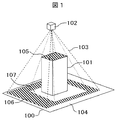
先ず、図1を参照して好ましい例を説明する。図1は実際に撮影された領域と撮影されなかった領域を表した模式図である。図1において被写体となる構造物として板状の部材100と直方体の部材101から構成され、地図を成す。102はカメラであり、103はカメラ102の視界を表す四角錐状の領域である。104は視界103内に入らない未撮影領域、105と106は被撮影領域、107は視界103の範囲には入るものの構造物101の陰となり撮影されない領域を表す。単にカメラの位置と方向に基づいて視界103に入る全ての領域を撮影済みと判断すると、地図上における領域104は未撮影領域として正しく判断され、領域105と領域106は被撮影領域として正しく判断されるが、視界103内の領域107については誤って撮影済み領域と判断されてしまう。   First, a preferred example will be described with reference to FIG. FIG. 1 is a schematic diagram showing a region actually captured and a region not captured. In FIG. 1, the structure as a subject is composed of a plate-like member 100 and a rectangular parallelepiped member 101, and forms a map. Reference numeral 102 denotes a camera, and reference numeral 103 denotes a quadrangular pyramid area representing the field of view of the camera 102. Reference numeral 104 denotes an unphotographed area that does not fall within the field of view 103, 105 and 106 denote areas to be photographed, and 107 denotes an area that falls within the range of the field of view 103 but is behind the structure 101 and is not photographed. If it is determined that all areas that fall within the field of view 103 have been photographed simply based on the position and direction of the camera, the area 104 on the map is correctly determined as an unphotographed area, and the areas 105 and 106 are correctly determined as areas to be imaged. However, the area 107 in the field of view 103 is erroneously determined as a photographed area.

そこで、カメラ102の位置から視界103の範囲内へ色を投影し、領域104、107が未撮影領域であることを作業者が容易に確認できるように被撮影領域である領域105、106とは異なる色の地図として作業者へ表示する。ここで、直方体の部材101の側面も未撮影領域となり、板状の部材100と直方体の部材101とが離れている場合は、2つの部材の間も未撮影領域となることは言うまでもない。
(第1の実施の形態)
以下、さらに具体的に構造物を点検するための画像を取得する点検カメラシステム200を例として説明する。
Therefore, the regions 105 and 106 that are the imaged regions are projected so that the operator can easily confirm that the regions 104 and 107 are unphotographed regions by projecting colors from the position of the camera 102 into the field of view 103. Display to the worker as a different color map. Here, it goes without saying that the side surface of the rectangular parallelepiped member 101 is also an unphotographed area, and when the plate-like member 100 and the rectangular parallelepiped member 101 are separated, the area between the two members is also an unphotographed area.
(First embodiment)
Hereinafter, the inspection camera system 200 that acquires an image for inspecting a structure will be described more specifically as an example.

図2は、第1の実施の形態における点検カメラシステム200の構成例を示す図である。点検カメラシステム200は、撮影部201、演算部202、記憶部203、表示部204、入力部205を備え、演算部202は、入力部205を通じて与えられる作業者の指示に基づき、撮影部201により点検対象の構造物を撮影し、記憶部203に保存している地図に対し撮影済み箇所を算出し、その結果を表示部204により表示する。   FIG. 2 is a diagram illustrating a configuration example of the inspection camera system 200 according to the first embodiment. The inspection camera system 200 includes an imaging unit 201, a calculation unit 202, a storage unit 203, a display unit 204, and an input unit 205. The calculation unit 202 is operated by the imaging unit 201 based on an operator instruction given through the input unit 205. A structure to be inspected is photographed, a photographed location is calculated for a map stored in the storage unit 203, and the result is displayed on the display unit 204.

撮影部201は自身の視界内に存在する点検対象の構造物を撮影する機器であり、モノクロームカメラ、カラーカメラなどとして実装される。なお、撮影部201が1台の例を示しているが、複数台でも良い。   The photographing unit 201 is a device that photographs a structure to be inspected that exists within its own field of view, and is implemented as a monochrome camera, a color camera, or the like. In addition, although the example of the imaging | photography part 201 is shown, multiple units | sets may be sufficient.

演算部202は、入力部205を通じての作業者からの指示の認識、撮影部201の制御、記憶部203の制御、表示部204の制御、撮影部201の位置姿勢推定、被撮影領域の特定、撮影情報含有地図の作成、表示画面の生成を行い、CPU206とRAM207の組合せとして実装される。演算部202は汎用のコンピュータであっても良い。演算部202は役割毎に分けられた複数のCPU206及びRAM207で構成されていても良い。CPU206は、記憶部203に記録されている各種プログラムをRAM207に読み出して実行することにより、後で説明する各種機能を実現する。   The calculation unit 202 recognizes an instruction from the operator through the input unit 205, controls the photographing unit 201, controls the storage unit 203, controls the display unit 204, estimates the position and orientation of the photographing unit 201, specifies a region to be photographed, A shooting information-containing map is generated and a display screen is generated, which is implemented as a combination of the CPU 206 and the RAM 207. The calculation unit 202 may be a general-purpose computer. The calculation unit 202 may be composed of a plurality of CPUs 206 and a RAM 207 divided for each role. The CPU 206 implements various functions described later by reading out various programs recorded in the storage unit 203 to the RAM 207 and executing them.

記憶部203は外部記憶装置であり、例えばハードディスク、フロッピー(登録商標)ディスク、USBメモリなどとして実装され、演算部202からの制御に基づき、情報の読み出し、変更、追加、削除を行う。   The storage unit 203 is an external storage device, which is mounted as, for example, a hard disk, a floppy (registered trademark) disk, or a USB memory, and reads, changes, adds, and deletes information based on the control from the calculation unit 202.

表示部204は例えばカラー表示可能なディスプレイやモニタなどとして実装され、演算部202から図5に示す表示部通信プログラム502に基づき送られる画像情報を表示する。   The display unit 204 is mounted as a display or monitor capable of color display, for example, and displays image information sent from the calculation unit 202 based on the display unit communication program 502 shown in FIG.

入力部205はマウス、キーボード、タッチパネル、テレビゲーム用コントローラなどの組合せとして実装され、作業者の意思を演算部202に伝えるものである。演算部202は、入力部205から送られた入力信号を図5に示す入力部通信プログラム503に基づき指示として認識し、その指示に応じた各種機能を実行する。   The input unit 205 is implemented as a combination of a mouse, a keyboard, a touch panel, a video game controller, and the like, and transmits the operator's intention to the calculation unit 202. The computing unit 202 recognizes the input signal sent from the input unit 205 as an instruction based on the input unit communication program 503 shown in FIG. 5, and executes various functions according to the instruction.

点検カメラシステム200は、その撮影部201を、作業者が保持する、あるいは車両など駆動機構を持つ装置に搭載するなどして、撮影部201が移動しながら、点検対象構造物を連続撮影するように運用される。表示部204並びに入力部205は作業者が保持するが、撮影部201、演算部202、表示部204並びに入力部205について、それぞれの間の物理的距離は問わない。また、演算部202は、機能に応じて二つ以上に分割されていても良く、撮影部201側、表示部204並びに入力部205側などに分かれていても良い。その場合、分割された演算部202の間を有線あるいは無線の通信により繋ぎ、互いの情報を交換することで各要素機能を連続的に動作させることで実現される。   The inspection camera system 200 continuously photographs the inspection target structure while the photographing unit 201 moves, for example, by mounting the photographing unit 201 on an apparatus held by an operator or mounted on a device having a driving mechanism such as a vehicle. To be used. The display unit 204 and the input unit 205 are held by an operator, but the physical distance between the imaging unit 201, the calculation unit 202, the display unit 204, and the input unit 205 is not limited. In addition, the calculation unit 202 may be divided into two or more according to functions, and may be divided into the photographing unit 201 side, the display unit 204, the input unit 205 side, and the like. In that case, the divided arithmetic units 202 are connected by wired or wireless communication, and each element function is continuously operated by exchanging information with each other.

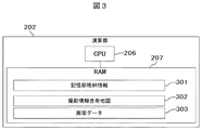
図3は、演算部202のRAM207で保持される主要な情報の構成例を表す図である。演算部202のRAM207では、記憶部格納情報301の他、撮影情報含有地図302、画面データ303を保持する。記憶部格納情報301は、点検カメラシステム200の起動時に、演算部202が記憶部203に格納されている情報を読み込むことでRAM207上に生成される。RAM207上の記憶部格納情報301は点検カメラシステム200の動作中に更新されていくが、演算部202は記憶部203に格納している情報を必ずしも連動して更新しなくとも良い。ただし、点検カメラシステム200の動作を終了するときに、演算部202は、記憶部格納情報301に基づき、記憶部203に格納している情報を更新する。撮影情報含有地図302、画面データ303に関しては図4〜6を用いて記憶部203を説明した後で記憶部203に格納される情報に基づいて説明する。   FIG. 3 is a diagram illustrating a configuration example of main information held in the RAM 207 of the calculation unit 202. The RAM 207 of the calculation unit 202 holds the shooting information containing map 302 and the screen data 303 in addition to the storage unit storage information 301. The storage unit storage information 301 is generated on the RAM 207 when the operation unit 202 reads information stored in the storage unit 203 when the inspection camera system 200 is activated. The storage unit storage information 301 on the RAM 207 is updated during the operation of the inspection camera system 200, but the calculation unit 202 does not necessarily update the information stored in the storage unit 203 in conjunction with it. However, when the operation of the inspection camera system 200 ends, the calculation unit 202 updates the information stored in the storage unit 203 based on the storage unit storage information 301. The imaging information containing map 302 and the screen data 303 will be described based on information stored in the storage unit 203 after the storage unit 203 has been described with reference to FIGS.

図4は、記憶部203に格納される情報の構成例を表す図である。記憶部203には、共通プログラム401、共通パラメータ402、撮影部位置姿勢推定プログラム403が格納される。   FIG. 4 is a diagram illustrating a configuration example of information stored in the storage unit 203. The storage unit 203 stores a common program 401, a common parameter 402, and an imaging unit position / orientation estimation program 403.

図5は記憶部203に格納される共通プログラム401の構成例を表す図である。共通プログラム401は、撮影部201、表示部204、入力部205と所定の通信プロトコルによりそれぞれ通信を実現する通信プログラム501〜503、撮影部201と表示部205のそれぞれの制御プログラム504、505、被撮影領域を特定するプログラム506、撮影情報含有地図302を作成するプログラム507、表示部204に表示する画面データ303を作成するプログラム508、地図表示のために仮想空間上に設置されるカメラのパラメータを変更するプログラム509、510を含む。プログラムの具体的な処理内容に関しては図10を用いて後で説明する。   FIG. 5 is a diagram illustrating a configuration example of the common program 401 stored in the storage unit 203. The common program 401 includes communication programs 501 to 503 for realizing communication with the photographing unit 201, the display unit 204, and the input unit 205 using a predetermined communication protocol, control programs 504 and 505 for the photographing unit 201 and the display unit 205, A program 506 for specifying a shooting area, a program 507 for creating a shooting information-containing map 302, a program 508 for creating screen data 303 to be displayed on the display unit 204, and parameters of a camera installed in a virtual space for map display It includes programs 509 and 510 to be changed. The specific processing contents of the program will be described later with reference to FIG.

図6は記憶部203に格納される共通パラメータ402の構成例を表す図である。共通パラメータ402は、画面中の地図、撮影画像、撮影ON/OFFボタンを表示するエリア601〜603、入力部205からの信号と連動して表示部204の画面上を移動するカーソルの位置604、撮影中か否かを表すパラメータ605、表示部204に表示するユーザインターフェースの画像606、地図に対し撮影済み領域を図示する際に用いる色情報607、撮影部201の撮影パラメータ608、609、微小領域の組合せで表現される地図610、撮影済みの画像群611、地図内の微小領域に対する撮影情報を表すデータ612、前回推定した撮影部201の位置姿勢613、地図表示のために仮想空間上に設置されるカメラのパラメータ614、615を含む。   FIG. 6 is a diagram illustrating a configuration example of the common parameter 402 stored in the storage unit 203. The common parameter 402 includes areas 601 to 603 for displaying a map, a photographed image, a photographing ON / OFF button on the screen, a cursor position 604 that moves on the screen of the display unit 204 in conjunction with a signal from the input unit 205, A parameter 605 indicating whether or not shooting is in progress, a user interface image 606 to be displayed on the display unit 204, color information 607 used for illustrating a shot area on a map, shooting parameters 608 and 609 of the shooting unit 201, and a minute area A map 610 expressed by a combination of the above, a group of captured images 611, data 612 representing shooting information for a small area in the map, a previously estimated position and orientation 613 of the shooting unit 201, and installed in a virtual space for map display Camera parameters 614, 615.

ここで、画面中の地図、撮影画像、撮影ON/OFFボタンを表示するエリア601〜603は表示部204の画面中における各エリアの左上の頂点の2次元的位置、エリアの幅、エリアの高さの情報がそれぞれ格納されており、各エリアは全て矩形状である。   Here, the areas 601 to 603 for displaying the map, the photographed image, and the photographing ON / OFF button on the screen are the two-dimensional position of the upper left vertex of each area on the screen of the display unit 204, the width of the area, and the height of the area. Each information is stored, and each area is rectangular.

カーソル位置604は、表示部204の画面中に表示されるカーソルの2自由度位置を表している。入力部205を介して作業者がその位置の変更を伝えることができ、演算部202は、入力部205からの信号に基づきカーソル位置604の値を変更し、作業者による入力部205を介した入力と表示部204に表示されるカーソルの動きが連動する。   A cursor position 604 represents a two-degree-of-freedom position of the cursor displayed on the screen of the display unit 204. The operator can notify the change of the position via the input unit 205, and the calculation unit 202 changes the value of the cursor position 604 based on the signal from the input unit 205, and the operator inputs the change via the input unit 205. The input and the movement of the cursor displayed on the display unit 204 are linked.

撮影ON/OFF605は、点検カメラシステム200が撮影中か否かの状態を表す情報である。点検カメラシステム200の起動時に演算部202が撮影ON/OFF605を読み出し、その情報に基づき撮影のスタートを決定する。また、点検カメラシステム200の動作中では、表示部204の画面内にてカーソルが画面中撮影ON/OFFボタンエリア内にある状態で、作業者が入力部205を通じて予め定められた信号を送ることにより、演算部202は入力部通信プログラム503に基づきその信号を撮影ON/OFF605の切り替え指示として認識し、撮影ON/OFF605の情報を反転させ、撮影中へと変更になる場合は撮影部201を起動して画像取得を開始し、停止中へと変更になる場合は撮影部201を停止して画像取得を終了する。   The shooting ON / OFF 605 is information indicating a state of whether or not the inspection camera system 200 is shooting. When the inspection camera system 200 is activated, the calculation unit 202 reads the shooting ON / OFF 605 and determines the start of shooting based on the information. Further, during the operation of the inspection camera system 200, the operator sends a predetermined signal through the input unit 205 in a state where the cursor is in the on-screen shooting ON / OFF button area on the screen of the display unit 204. Thus, the calculation unit 202 recognizes the signal as an instruction to switch the shooting ON / OFF 605 based on the input unit communication program 503, inverts the information of the shooting ON / OFF 605, and if the shooting unit 201 is changed to during shooting, The image acquisition is started and image acquisition is started. When the image acquisition is changed to stop, the photographing unit 201 is stopped and the image acquisition is ended.

ユーザインターフェース画像群606は、表示部204に表示される複数のユーザインターフェースのための画像を格納しており、カーソルの画像と撮影ON/OFFボタンの画像を含む。撮影ON/OFFボタンは、点検カメラシステム200が撮影中か否かの状態を作業員に伝える機能も同時に有していても良く、その場合、その画像は撮影中の状態を表すものと、停止中の状態とを表すものの2種類が含まれる。   The user interface image group 606 stores images for a plurality of user interfaces displayed on the display unit 204, and includes a cursor image and a shooting ON / OFF button image. The shooting ON / OFF button may also have a function of notifying the worker whether or not the inspection camera system 200 is shooting, and in that case, the image indicates the shooting state and the stop. There are two types, one representing the inside state.

撮影済み領域図示用色情報607は、地図に対し撮影済み領域を示すための色を表す。撮影済み領域を示すための色のみならず、複数の被撮影領域の中で最新の被撮影領域を示すための色、重要点検エリアを示すための色など複数存在していても良い。   The photographed area indicating color information 607 represents a color for indicating the photographed area on the map. There may be a plurality of colors such as a color for indicating the latest imaged area, a color for indicating an important inspection area, in addition to a color for indicating the imaged area.

撮影部画像サイズ608は、画像の幅wと高さhを画素数で表現したものである。また、撮影部201内部パラメータ307は、幅方向焦点距離α、高さ方向焦点距離β、画像中心幅方向座標ξ、画像中心高さ方向座標η、歪み補正用パラメータk1A、k2A、p1A、p2Aが含まれる。 The imaging unit image size 608 represents the width w A and the height h A of the image by the number of pixels. The photographing unit 201 internal parameters 307 include a width direction focal length α A , a height direction focal length β A , an image center width direction coordinate ξ A , an image center height direction coordinate η A , and distortion correction parameters k 1A , k. 2A , p 1A , p 2A are included.

地図610は、点検対象構造物の表面の色と形状を3次元的に表現する情報であり、複数の微小領域で構成される。図7は、地図610の例を視覚的に表現した図である。地図610は、点検対象構造物の表面を微小な平面の集合体として表現する。図7では、その平面の形状は四角形となっているが、3点以上の頂点を持つ多角形であれば良く、円や楕円であっても良い。各微小領域の情報は、微小領域のID番号、囲みの3次元座標、色、法線方向である。囲みの3次元座標は、多角形であればその頂点の3次元座標であり、円であれば中心及び半径、楕円であれば中心及び長半径、短半径、長軸方向である。色は単色、微小領域に貼付するテクスチャ画像などで表現される。法線方向については、多角形であれば、頂点の3次元座標の記述順によりその情報が付加され、円や楕円であれば、3自由度の法線ベクトルにより表現される。地図610は、点検対象構造物の設計データに基づき作成されても良いし、カメラやレーザ距離センサなどにより予め得られた計測結果に基づき作成されても良い。   The map 610 is information that three-dimensionally expresses the surface color and shape of the structure to be inspected, and is composed of a plurality of minute regions. FIG. 7 is a diagram visually representing an example of the map 610. The map 610 represents the surface of the inspection target structure as a collection of minute planes. In FIG. 7, the shape of the plane is a rectangle, but it may be a polygon having three or more vertices, and may be a circle or an ellipse. The information of each minute area includes the ID number of the minute area, the three-dimensional coordinates of the box, the color, and the normal direction. The three-dimensional coordinates of the box are the three-dimensional coordinates of the apex of the polygon, the center and radius of the circle, and the center, major radius, minor radius, and major axis direction of the ellipse. The color is expressed by a single color, a texture image to be attached to a minute area, or the like. As for the normal direction, if it is a polygon, the information is added according to the description order of the three-dimensional coordinates of the vertex, and if it is a circle or an ellipse, it is expressed by a normal vector of three degrees of freedom. The map 610 may be created based on the design data of the inspection target structure, or may be created based on a measurement result obtained in advance by a camera, a laser distance sensor, or the like.

撮影済み画像群611は、点検カメラシステム200の起動時から終了時までに撮影した画像の列であり、そのID番号と共に画像ファイルとして保存される。   The photographed image group 611 is a sequence of images photographed from the start to the end of the inspection camera system 200, and is stored as an image file together with its ID number.

撮影情報群612は、地図610の各微小領域に対して与えられる撮影に関する情報を格納する。その情報には、少なくとも、その微小領域が撮影済みか否かを表す情報が含まれる。撮影情報群612は、その微小領域が最新フレームの被撮影領域か否かを表す情報、その微小領域が重要点検エリアに含まれるか否かを表す情報を有していても良い。また、撮影済みの場合に、その微小領域が撮影されている撮影済み画像群611の画像のID番号を一つ以上格納可能としても良い。   The shooting information group 612 stores information related to shooting given to each minute area of the map 610. The information includes at least information indicating whether or not the minute area has been photographed. The imaging information group 612 may include information indicating whether or not the micro area is the imaging area of the latest frame, and information indicating whether or not the micro area is included in the important inspection area. Further, when the image has been captured, it is possible to store one or more ID numbers of images of the captured image group 611 in which the minute area is captured.

前回推定した撮影部の位置姿勢613は、撮影部201が1フレーム前の画像を撮影した際に、演算部202が、撮像部201位置姿勢推定プログラム403に基づき撮像部201の位置姿勢を推定した結果である。撮像部201の位置姿勢は、地図610の座標系を基準とし、3×3の回転行列Rと3自由度の並進ベクトルtとして表現される。   The position / orientation 613 of the imaging unit estimated last time is calculated by the calculation unit 202 based on the imaging / unit 201 position / orientation estimation program 403 when the imaging unit 201 captures an image of the previous frame. It is a result. The position and orientation of the imaging unit 201 are expressed as a 3 × 3 rotation matrix R and a translation vector t with 3 degrees of freedom with reference to the coordinate system of the map 610.

地図表示用仮想カメラ焦点距離614と地図表示用仮想カメラ位置姿勢615は表示部204へ被撮影領域などを表示する際の表示の視点を表す仮想カメラに関する情報を格納する。地図表示用仮想カメラ位置姿勢615は、地図610の座標系を基準とし、3×3の回転行列Rと3自由度の並進ベクトルtとして表現される。 The map display virtual camera focal length 614 and the map display virtual camera position / posture 615 store information related to the virtual camera that represents the viewpoint of display when displaying the imaged region or the like on the display unit 204. The map display virtual camera position / orientation 615 is expressed as a 3 × 3 rotation matrix R V and a translation vector t V of 3 degrees of freedom with reference to the coordinate system of the map 610.

記憶部203に格納される情報のうち、撮影済み画像群611以外は全て予め初期値が入力されている。前回推定した撮影部位置姿勢613の初期値には、撮影開始時における撮影部201の位置姿勢のおおよその値を入力しておく。その際に、撮影開始時における撮影部201の位置姿勢からも、前回推定した撮影部位置姿勢613の初期値として与えられた位置姿勢からも見える被写体構造物の部位が、多数存在する位置姿勢とする。   Of the information stored in the storage unit 203, initial values are input in advance except for the photographed image group 611. As an initial value of the imaging unit position and orientation 613 estimated last time, an approximate value of the position and orientation of the imaging unit 201 at the start of imaging is input. At that time, a position and orientation in which there are a large number of parts of the subject structure that can be seen from the position and orientation of the imaging unit 201 at the start of imaging as well as the position and orientation given as the initial values of the imaging unit position and orientation 613 estimated last time. To do.

以上の記憶部203に格納される情報に対して、RAM207の撮影情報含有地図302は、演算部202が、撮影情報含有地図作成プログラム507、地図610、撮影済み領域図示用色情報607、撮影情報群612に基づき作成される。図8は、撮影情報含有地図302の例を視覚的に表す図である。撮影情報含有地図302は、地図610の各微小領域に対し、撮影済み領域図示用色情報607と撮影情報群612に基づき色付けされたものである。   In contrast to the information stored in the storage unit 203 described above, the calculation information 202 of the shooting information-containing map 302 in the RAM 207 is calculated by the calculation unit 202, the map 610, the color information 607 for displaying the shot area, the shooting information. Created based on group 612. FIG. 8 is a diagram visually representing an example of the shooting information containing map 302. The shooting information containing map 302 is obtained by coloring each minute area of the map 610 based on the shooting area indicating color information 607 and the shooting information group 612.

また、RAM207の画面データ303は、演算部202が、画面データ作成プログラム508、撮影情報含有地図302、撮影済み画像群611の内の一枚の画像、カーソル位置604、撮影ON/OFF605、画面中における地図、撮影画像、撮影ON/OFFボタンの表示用エリア601〜603、ユーザインターフェース画像群606、地図表示用仮想カメラのパラメータ614、615に基づき作成される。図9は、画面データ303の例を表す図である。演算部202は、表示部通信プログラム502に基づき、画面データ303を表示部204へ送り、表示部204は画面データ303にしたがって画面を表示する。   Further, the screen data 303 of the RAM 207 is calculated by the calculation unit 202 when the screen data creation program 508, the shooting information containing map 302, one image in the shot image group 611, the cursor position 604, shooting ON / OFF 605, Are created based on parameters 614 and 615 of a map, a photographed image, display areas 601 to 603 for photographing ON / OFF buttons, a user interface image group 606, and a map display virtual camera. FIG. 9 is a diagram illustrating an example of the screen data 303. The computing unit 202 sends screen data 303 to the display unit 204 based on the display unit communication program 502, and the display unit 204 displays a screen according to the screen data 303.

画面データ303のうち画面中地図表示用エリア601に表示する画像は、3次元的な情報を持つ撮影情報含有地図302をその空間内に仮想的に設置した地図表示用仮想カメラから見た画像である。地図表示用仮想カメラは、画面中地図表示用エリア601をその画像サイズとし、撮影地図表示用仮想カメラ焦点距離614、表示用仮想カメラ位置姿勢615によって地図表示用仮想カメラの状態が定義される。地図表示用仮想カメラ焦点距離変更プログラム509は、入力部205からの入力信号に対し、地図表示用仮想カメラ焦点距離614の変更処理を行うプログラムである。また、地図表示用仮想カメラ位置姿勢変更プログラム510は、入力部205からの入力信号に対し、地図表示用仮想カメラ位置姿勢615の変更処理を行うプログラムである。この二つのプログラムにより、画面データ152内の画面中地図表示用エリア601に表示される撮影情報含有地図302の見え方を変更することができる。   The image displayed in the on-screen map display area 601 in the screen data 303 is an image viewed from a map display virtual camera in which a shooting information containing map 302 having three-dimensional information is virtually installed in the space. is there. The map display virtual camera has an on-screen map display area 601 as its image size, and the state of the map display virtual camera is defined by the shooting map display virtual camera focal length 614 and the display virtual camera position and orientation 615. The map display virtual camera focal length change program 509 is a program for changing the map display virtual camera focal length 614 in response to an input signal from the input unit 205. The map display virtual camera position / orientation change program 510 is a program for changing the map display virtual camera position / orientation 615 in response to an input signal from the input unit 205. With these two programs, it is possible to change the appearance of the shooting information containing map 302 displayed in the on-screen map display area 601 in the screen data 152.

図10は、演算部202の処理例を説明するフローチャートである。先ず、点検カメラシステム200が起動し、演算部202が、記憶部203に格納されている全てのデータを、RAM207内の記憶部格納情報301へと読み込み、前回推定した撮影部の位置姿勢613の初期値付近に実際の撮影部201が存在している状態で、撮影ON/OFF605がONに変更になったところでスタートする。   FIG. 10 is a flowchart for explaining a processing example of the calculation unit 202. First, the inspection camera system 200 is activated, and the calculation unit 202 reads all the data stored in the storage unit 203 into the storage unit storage information 301 in the RAM 207 to determine the position and orientation 613 of the imaging unit estimated last time. The process is started when the photographing ON / OFF 605 is changed to ON while the actual photographing unit 201 exists near the initial value.

スタートすると、演算部202は、撮影部通信プログラム501と撮影部制御プログラム504に基づき、撮影部201に構造物を撮影させ、画像を取得する(S100)。続いて、演算部202は、得られた画像にID番号を付加し、RAM207内の記憶部格納情報301における撮影済み画像群611に最新画像としてID番号と共に格納する(S101)。さらに、1フレーム前の画像をRAM207内に格納している場合に、演算部202はその画像をそのID番号と共に記憶部203内の撮影済み画像群611へと格納し、その画像およびID番号をRAMから削除する(S102)。演算部202が、定期的にRAM内に確保される画像を削除することにより、RAM内のデータ量が積算されることを防ぐことができる。   When started, the calculation unit 202 causes the photographing unit 201 to photograph the structure based on the photographing unit communication program 501 and the photographing unit control program 504, and acquires an image (S100). Subsequently, the calculation unit 202 adds an ID number to the obtained image, and stores it as the latest image in the captured image group 611 in the storage unit storage information 301 in the RAM 207 together with the ID number (S101). Further, when the image of the previous frame is stored in the RAM 207, the calculation unit 202 stores the image together with the ID number in the captured image group 611 in the storage unit 203, and the image and the ID number are stored. Delete from the RAM (S102). It is possible to prevent the amount of data in the RAM from being accumulated by the calculation unit 202 deleting the images secured in the RAM periodically.

続いて、演算部202は、RAM207内の記憶部格納情報301における撮影部位置姿勢推定プログラム403に基づき、前回推定した撮影部の位置姿勢613から撮影する画像を予測して予測画像をRAM207内に作成し、その予測画像と最新画像とを照合し、現在の撮影部201の位置姿勢を推定する(S103)。予測画像の作成には、撮影部画像サイズ608、撮影部内部パラメータ609、地図610、前回推定した撮影部の位置姿勢613を利用する。   Subsequently, the arithmetic unit 202 predicts an image to be captured from the previously estimated position / orientation 613 of the imaging unit based on the imaging unit position / orientation estimation program 403 in the storage unit storage information 301 in the RAM 207 and stores the predicted image in the RAM 207. The predicted image and the latest image are collated, and the current position and orientation of the photographing unit 201 are estimated (S103). For creating the predicted image, the imaging unit image size 608, the imaging unit internal parameter 609, the map 610, and the previously estimated imaging unit position and orientation 613 are used.

作成する予測画像の各画素に対し、前回推定した撮影部201の3次元位置からその画素に対応する方向に延びる半直線を定義し、地図610内の全微小領域のうちその半直線と交わるものを算出し、半直線と微小領域との交点までの距離が前回推定した撮影部201の3次元位置に最も近い点が撮影されるとみなし、その点に対応する色をその画素に色付けする。これにより、予測画像を作成することができる。   For each pixel of the predicted image to be created, a half line extending in the direction corresponding to the pixel from the previously estimated three-dimensional position of the photographing unit 201 is defined, and intersects with the half line of all minute regions in the map 610 And the point closest to the three-dimensional position of the photographing unit 201 estimated last time is estimated as the distance to the intersection of the half line and the minute area, and the pixel is colored with a color corresponding to the point. Thereby, a predicted image can be created.

予測画像の作成後、最新画像と撮影部画像サイズ608、撮影部内部パラメータ609に基づいてレンズ歪みを補正した補正画像を作成する。さらに、予測画像から構造物の頂点などの特徴点を抽出し、各特徴点を中心に10画素×10画素程度の領域を切り出し、その領域を補正画像上で探索することにより、予測画像−補正画像間の対応点を複数個取得する。全ての対応点がエピポーラ幾何拘束を満たすように、前回推定した撮影部201位置姿勢と現在の位置姿勢との相対関係を求め、その後、現在の撮影部201の位置姿勢の推定値を決定することができる。   After creating the predicted image, a corrected image is created by correcting the lens distortion based on the latest image, the photographing unit image size 608, and the photographing unit internal parameter 609. Further, by extracting feature points such as vertices of the structure from the predicted image, cutting out an area of about 10 pixels × 10 pixels around each feature point, and searching the area on the corrected image, the predicted image-correction Get multiple corresponding points between images. Obtaining the relative relationship between the previously estimated position and orientation of the imaging unit 201 and the current position and orientation so that all corresponding points satisfy the epipolar geometric constraint, and then determining the estimated position and orientation of the current imaging unit 201 Can do.

続いて、演算部202はRAM207内の記憶部格納情報301における被撮影微小領域特定プログラム506に基づき、本フレームにおける被撮影微小領域を特定し、RAM207内に格納する(S104)。その際に、現在の位置姿勢の推定値、撮影部画像サイズ608、撮影部内部パラメータ609、地図610を使用する。   Subsequently, the calculation unit 202 specifies the to-be-photographed micro area in the main frame based on the to-be-photographed micro area specifying program 506 in the storage unit storage information 301 in the RAM 207, and stores it in the RAM 207 (S104). At that time, the estimated value of the current position and orientation, the imaging unit image size 608, the imaging unit internal parameter 609, and the map 610 are used.

予測画像作成と同様に、推定した現在の撮影部201の3次元位置から地図610内の各微小領域への方向に延びる半直線を視界の範囲内で定義し、地図610内の全微小領域のうちその半直線と交わるものを算出し、複数の交わるものの中で半直線と微小領域との交点までの距離が推定した現在の撮影部201の3次元位置に最も近い点が撮影されるとみなし、その微小領域を被撮影微小領域として特定することができる。最も近い点の算出には、撮影部201の3次元位置から複数の交点までの距離を計算しソートしても良いし、撮影部201の3次元位置を原点として複数の交点のx座標あるいはy座標のいずれかを比較するなどしても良い。一つしか交わるものがない場合はその交点が最も近い点となることは言うまでもないが、交わるものの数を判定して一つしか交わるものがない場合にその交点を最も近い点としても良いし、複数の交わるものに対応できる処理の結果として一つしか交わるものがない場合にその交点を最も近い点とするなどしても良い。   Similarly to the prediction image creation, a half line extending in the direction from the estimated current three-dimensional position of the imaging unit 201 to each minute area in the map 610 is defined within the field of view, and all the minute areas in the map 610 are defined. Of these, a point intersecting with the half line is calculated, and a point closest to the current three-dimensional position of the photographing unit 201 estimated from the distance between the half line and the minute region is assumed to be photographed. The micro area can be specified as the micro area to be imaged. For calculating the closest point, the distance from the three-dimensional position of the photographing unit 201 to a plurality of intersections may be calculated and sorted, or the x-coordinates or y of the plurality of intersections with the three-dimensional position of the photographing unit 201 as the origin. Any of the coordinates may be compared. It goes without saying that if there is only one intersection, the intersection will be the closest point, but if the number of intersections is determined and there is only one intersection, that intersection may be the closest point, If there is only one intersection as a result of processing that can handle a plurality of intersections, the intersection may be set as the closest point.

ここで、特定した微小領域の構造物の内側から外側へ向かう法線方向と半直線の方向との成す角が90度以下の場合すなわち直方体の部材101などの構造物の内側から外側へ向けて撮影した状態となる場合、実際にはその微小領域は撮影されない。このようなケースは地図が不完全であり、撮影部201へさらに近い微小領域が地図から欠損している場合に発生するため、この成す角の大きさが90度より大きい場合にその微小領域を被撮影微小領域として特定することがより望ましい。   Here, when the angle formed between the normal direction from the inside to the outside of the structure of the specified minute region and the direction of the half line is 90 degrees or less, that is, from the inside to the outside of the structure such as the rectangular parallelepiped member 101. When the photographed state is obtained, the minute area is not actually photographed. Such a case occurs when the map is incomplete and a minute region closer to the photographing unit 201 is missing from the map. Therefore, if the angle formed is larger than 90 degrees, the minute region is not displayed. It is more desirable to specify as a micro area to be photographed.

続いて、演算部202は、特定した被撮影微小領域に対し、RAM207内の記憶部格納情報301における撮影情報群612のうち撮影済みか否かを表す情報を撮影済みとして更新する(S105)。その後、演算部202は、RAM207内の撮影情報含有地図作成プログラム507に基づき、撮影情報含有地図302を作成する(S106)。   Subsequently, the computing unit 202 updates the information indicating whether or not the shooting has been performed in the shooting information group 612 in the storage unit storage information 301 in the RAM 207 with respect to the specified minute area to be shot as being shot (S105). Thereafter, the calculation unit 202 creates the shooting information containing map 302 based on the shooting information containing map creation program 507 in the RAM 207 (S106).

撮影情報群612に微小領域が撮影されている画像のID番号を入力可能としている場合、そこに最新画像のID番号を入力しても良い。   When the ID number of the image in which the minute area is captured can be input to the imaging information group 612, the ID number of the latest image may be input there.

撮影情報含有地図302の作成には、撮影済み領域図示用色情報607、地図610、撮影情報群612を用いる。具体的には、地図610をRAM207上でコピーし、撮影情報群612の撮影済みか否かを表す情報が撮影済みとなっている微小領域に対し、その色情報を撮影済み領域図示用色情報607に基づき変更する。その際に、撮影済み領域図示用色情報607をそのまま利用しても良いが、地図610に記されているその微小領域の色情報と撮影済み領域図示用色情報607とを一定の割合で混ぜ合わせて作成した色を利用すると、作業者が点検対象構造物のどの部位が計測済みであるかを視認し易くなる。   For the creation of the photographing information-containing map 302, the photographed area indicating color information 607, the map 610, and the photographing information group 612 are used. Specifically, the map 610 is copied on the RAM 207, and the color information is displayed on the micro area where the information indicating whether or not the shooting information group 612 has been shot is taken. Change based on 607. At that time, the photographed area indicating color information 607 may be used as it is, but the color information of the minute area indicated on the map 610 and the photographed area indicating color information 607 are mixed at a certain ratio. When the color created in combination is used, the operator can easily visually recognize which part of the inspection target structure has been measured.

また、撮影情報群612及び撮影済み領域図示用色情報607の中に、重点点検領域か否かを表す情報及びそれに対応する色を含めておき、重点点検領域のうち未撮影の微小領域を重点点検領域の色とすることで、今後どの領域を撮影すれば良いか作業者が視認しやすくなる。さらに、撮影済み領域図示用色情報305の中に最新フレームの被撮影領域を表すための色を保持しておき、S104で特定した被撮影微小領域をその色とすることで、現在の撮影部201がどの領域を撮影しているのか、撮影部201を今後どの方向に移動すれば良いかを作業者が視認しやすくなる。最新フレームの被撮影領域が移動した場合は、一つ前のフレームの被撮影領域の色を最新フレームの被撮影領域を表すための色以外の色へ変更しても良いし、一つ前のフレームの被撮影領域の色は残して最新フレームの被撮影領域を表すための色を常に変更し、作業者へは最新フレームの被撮影領域を表すための色が何色であるかを表示するなどしても良い。   Further, information indicating whether or not it is a priority inspection region and the corresponding color are included in the photographing information group 612 and the photographed region indicating color information 607, and an unphotographed minute region is emphasized in the priority inspection region. By using the color of the inspection area, it becomes easier for the operator to visually recognize which area should be photographed in the future. Furthermore, a color for representing the imaged area of the latest frame is held in the imaged area indicating color information 305, and the current imaged unit is obtained by setting the imaged minute area specified in S104 as the color. It becomes easier for the operator to visually recognize which area 201 is photographing and in which direction the photographing unit 201 should be moved in the future. When the shooting area of the latest frame has moved, the color of the shooting area of the previous frame may be changed to a color other than the color used to represent the shooting area of the latest frame. The color of the imaged area of the latest frame is always changed, and the color for representing the imaged area of the latest frame is always changed, and the operator is informed of the color used to represent the imaged area of the latest frame. You may do it.

続いて、演算部202は、RAM207内の記憶部格納情報301における画面データ作成プログラム508により、画面データを作成し(S107)、表示部通信プログラム502と表示部制御プログラム505により、表示部204に画面データ303を表示させる(S108)。   Subsequently, the calculation unit 202 creates screen data by the screen data creation program 508 in the storage unit storage information 301 in the RAM 207 (S107), and the display unit 204 creates the screen data by the display unit communication program 502 and the display unit control program 505. The screen data 303 is displayed (S108).

画面データ303の作成には、撮影情報含有地図302、画面中の地図、画像、撮影ON/OFFボタンのエリア601〜603、カーソル位置604、撮影ON/OFF605、ユーザインターフェース画像群606、撮影済み画像群611に格納されている最新画像、地図表示用仮想カメラの焦点距離及び位置姿勢614、615を用いる。   To create the screen data 303, the shooting information containing map 302, the map on the screen, the image, the shooting ON / OFF button areas 601 to 603, the cursor position 604, the shooting ON / OFF 605, the user interface image group 606, and the shot image The latest image stored in the group 611, the focal length and the position and orientation 614, 615 of the map display virtual camera are used.

まず、画面中地図表示用エリア601に表示する画像を作成する。撮影情報含有地図302に対し、画面中地図表示用エリア601を画像サイズとし、地図表示用仮想カメラ焦点距離614を焦点距離とする仮想カメラを、地図表示用仮想カメラ位置姿勢615に仮想的に出現させて表示の視点とし、その仮想カメラによる仮想的な撮影結果を表示画像とする。地図表示用仮想カメラ位置姿勢615に記された3次元位置に表示画面の各画素を置き、その各画素から撮影方向に延びる半直線を定義し、撮影情報含有地図302内の全微小領域のうちその半直線と交わるものを算出し、半直線と微小領域との交点までの距離が地図表示用仮想カメラ位置姿勢615に記された3次元位置に最も近い点が撮影されるとみなし、撮影情報含有地図302のその最も近い点の色を表示画像のその画素に色付けする。これにより、撮影情報含有地図302に対する表示画像を作成することができる。   First, an image to be displayed in the on-screen map display area 601 is created. A virtual camera having an on-screen map display area 601 as an image size and a map display virtual camera focal length 614 as a focal length appears virtually in the map display virtual camera position and orientation 615 with respect to the shooting information-containing map 302. Thus, the display viewpoint is used, and the virtual imaging result of the virtual camera is used as the display image. Each pixel of the display screen is placed at the three-dimensional position described in the map display virtual camera position and orientation 615, and a half line extending in the shooting direction from each pixel is defined. The intersection with the half line is calculated, and it is assumed that the point closest to the three-dimensional position recorded in the map display virtual camera position and orientation 615 is the distance to the intersection between the half line and the minute area. The color of the closest point of the contained map 302 is colored to that pixel of the display image. Thereby, the display image with respect to the imaging | photography information containing map 302 can be produced.

図9における画面中の地図、画像、撮影ON/OFFボタンを表示するためのエリア601〜603を包含する表示ウィンドウ904に対応する画面データ303をRAM207上に作成するため、エリア901に対応する画面中地図表示用エリア601に作成した表示画像を、エリア902に対応する画面中画像表示用エリア602に撮影済み画像群611に格納されている最新画像あるいは所定の条件を満たす画像を、エリア903に対応する画面中撮影ON/OFFボタンエリア603にユーザインターフェース画像群606に格納されている撮影ON/OFFボタン画像907のうち撮影ON/OFF605に対応する画像を、それぞれ表示ウィンドウに対応するデータへ合成する。その上から、ユーザインターフェース画像群606に格納されているカーソル画像905をカーソル位置604に基づきエリア906へ合成する。この結果が画面データ303となる。   Since the screen data 303 corresponding to the display window 904 including the areas 601 to 603 for displaying the map, the image, and the shooting ON / OFF button on the screen in FIG. 9 is created on the RAM 207, the screen corresponding to the area 901 is displayed. A display image created in the middle map display area 601 is displayed in the area 903 as a latest image stored in the captured image group 611 or an image satisfying a predetermined condition in the on-screen image display area 602 corresponding to the area 902. Of the shooting ON / OFF button images 907 stored in the user interface image group 606 in the corresponding on-screen shooting ON / OFF button area 603, the image corresponding to the shooting ON / OFF 605 is combined with the data corresponding to the display window. To do. Then, the cursor image 905 stored in the user interface image group 606 is combined with the area 906 based on the cursor position 604. The result is screen data 303.

演算部202は、入力部通信プログラム503に基づき入力部205からの入力信号を指示として認識し、その指示に対応する動作を実行する(S109)。その指示には、少なくとも、撮影ON/OFF605の切り替え、カーソル位置604の移動、地図表示用仮想カメラ焦点距離614の変更、地図表示用仮想カメラ位置姿勢615の変更が含まれる。そして、演算部202は、撮影ON/OFF605の値に応じて、S100からの一連の動作を再度繰り返すか、点検カメラシステム200を終了するかを選択する(S110)。終了する際には、RAM207内の記憶部格納情報301を記憶部203にコピーする。ただし、撮影済み画像群611については、既にコピーした画像へ上書きするのではなく、最新画像をそのID番号と共に追加保存しても良い。   The calculation unit 202 recognizes an input signal from the input unit 205 as an instruction based on the input unit communication program 503, and executes an operation corresponding to the instruction (S109). The instruction includes at least switching of shooting ON / OFF 605, movement of the cursor position 604, change of the map display virtual camera focal length 614, and change of the map display virtual camera position and orientation 615. Then, the calculation unit 202 selects whether to repeat the series of operations from S100 again or to end the inspection camera system 200 according to the value of the shooting ON / OFF 605 (S110). When the process ends, the storage unit storage information 301 in the RAM 207 is copied to the storage unit 203. However, for the captured image group 611, the latest image may be additionally stored together with its ID number instead of overwriting the already copied image.

また、撮影情報群612に、撮影済みの微小領域に対しその微小領域が撮影されている画像のID番号を付加されている場合、撮影ON/OFF605が停止中を表す際に、作業者がカーソル905を撮影済み微小領域に重ね合わせて予め定義した信号を送ることで、その微小領域を撮影した画像が画面中画像表示用エリア602に表示されるようにしても良い。これにより、作業者が撮影後にカーソル905のみによる仮想カメラなどの操作だけで撮影結果の再確認を容易に行うことができるようになる。   In addition, when an ID number of an image in which the minute area is photographed is added to the photographed minute area in the photographing information group 612, the operator moves the cursor when the photographing ON / OFF 605 indicates that it is stopped. An image obtained by photographing the minute area may be displayed in the on-screen image display area 602 by superimposing 905 on the photographed minute area and sending a predefined signal. As a result, the operator can easily reconfirm the shooting result only by operating the virtual camera or the like using only the cursor 905 after shooting.

画像撮影は亀裂などの発見を目的としていることから、点検対象構造物の表面は可能な限り垂直に撮影されることが望ましく、平行に近づくにつれて点検用途に利用不可能な画像となる。そこで、被撮影微小領域を特定する際に(S104)、最も近いという条件に加えて、その画像を撮影したときの撮影部201の位置姿勢と地図610から、微小領域の法線方向と撮影部201の3次元位置からその微小領域が写し出されている画素への方向の半直線との成す角を算出し、その成す角と予め与えられた閾値とを比較して平行に近くない場合にその微小領域が撮影されたとすることが望ましい。   Since the imaging is aimed at finding cracks and the like, it is desirable that the surface of the structure to be inspected be photographed as vertically as possible, and as it approaches parallel, the image becomes unusable for inspection purposes. Therefore, when specifying the micro area to be imaged (S104), in addition to the closest condition, the normal direction of the micro area and the imaging section are determined from the position and orientation of the imaging section 201 when the image is captured and the map 610. The angle formed by the half line in the direction from the three-dimensional position of 201 to the pixel in which the minute region is projected is calculated, and when the formed angle is compared with a predetermined threshold value, the angle is not nearly parallel. It is desirable that a minute area has been photographed.

点検対象構造物の表面は可能な限り拡大して撮影されていることが望ましく、1画素に対応する面積が亀裂の太さに対して大き過ぎる場合は点検用途に利用不可能な画像となる。そこで、被撮影微小領域を特定する際に(S104)、最も近いという条件や平行に近くないという条件に加えて、その画像を撮影したときの撮影部201の位置姿勢と撮影部201の撮影に関するサイズやパラメータ608、609、地図610から、その微小領域が写し出されている画素数を算出し、微小領域の面積をその画素数で割った1画素当たりの面積の値が予め与えられた閾値よりも小さい場合にその微小領域が撮影されたと見なすことが望ましい。   The surface of the structure to be inspected is desirably enlarged as much as possible, and if the area corresponding to one pixel is too large for the thickness of the crack, the image cannot be used for inspection purposes. Therefore, when specifying the micro area to be imaged (S104), in addition to the condition of being closest or not being parallel, the position and orientation of the imaging unit 201 when the image is captured and the imaging of the imaging unit 201 are related. From the size, parameters 608 and 609, and the map 610, the number of pixels in which the minute area is projected is calculated, and the area value per pixel obtained by dividing the area of the minute area by the number of pixels is calculated based on a predetermined threshold value. If it is small, it is desirable that the minute area is taken.

撮影対象群612について、撮影済みの微小領域に対しその微小領域が撮影されている画像のID番号を付加している場合、さらに、上記の成す角や1画素当たりの面積あるいはそれらの組み合わせから算出される評価値を画像に与えて、その微小領域を撮影している画像が複数存在する際にはそれらの値に基づき優先順位付けを行い、優先順位の高い順に表示できるようにその画像のID番号を保存しても良い。これにより、撮影後に画像を再点検する際に、条件の良い画像のみを確認することができ、再点検の時間を短縮することができる。なお、一つの画像を構成する複数の微小領域で上記の成す角や1画素当たりの面積の異なる場合は最低値を画像の評価値としても良い。   In the case where the ID number of the image in which the minute area is photographed is added to the photographed minute area with respect to the photographing target group 612, the calculation is further performed from the angle formed above, the area per pixel, or a combination thereof. When there are a plurality of images capturing the minute area, prioritization is performed based on those values, and the IDs of the images are displayed so that they can be displayed in descending order of priority. You may save the number. As a result, when re-inspecting the image after shooting, only images with good conditions can be confirmed, and the time for re-inspection can be shortened. In addition, when the angle | corner and said area per pixel differ in several micro area | regions which comprise one image, it is good also considering the minimum value as an evaluation value of an image.

画面中地図表示用エリア601に関しても、上記の成す角や1画素当たりの面積あるいはそれらの組み合わせから算出される評価値に応じて撮影済み領域図示用色情報607の複数の色から特定の色を選択して撮影情報含有地図へ色付けし、作業者へどのような状態で撮影したかを認識させることにより、同じ領域を再度撮影し直すかの判断をさせても良い。   Also for the map display area 601 in the screen, a specific color is selected from a plurality of colors of the photographed area indicating color information 607 in accordance with the evaluation value calculated from the angle formed above, the area per pixel, or a combination thereof. It may be determined whether to re-shoot the same region by selecting and coloring the shooting information-containing map and allowing the operator to recognize in what state the shooting was performed.

さらに、現在の撮影部201の位置姿勢推定(S103)には、誤差の生じる場合がある。その誤差により半直線により構成された視界と実際に撮影された画像とにズレが生じ、被撮影微小領域の特定(S104)にも誤りが生じて、それが点検用画像の取得漏れにつながる場合もある。そこで、撮影した画像のうち予め定められた画素数の幅を持った外枠よりも内側の領域のみを被撮影微小領域として、ズレが生じても確実に撮影された領域のみを被撮影微小領域とすることにより点検用画像の取得漏れを抑えることもできる。ここで、外枠も被撮影微小領域として外枠と外枠よりも内側の領域との撮影済み領域図示用色情報の色を異なる色として、外枠であって点検用画像の取得漏れの可能性のあることを作業者へ認識させても良い。
(第2の実施の形態)
第2の実施の形態では、構造物を点検するための画像を取得する点検カメラシステムの他の例を説明する。
Furthermore, an error may occur in the current position / orientation estimation (S103) of the photographing unit 201. When the field of view constituted by the half line and the actually photographed image are shifted due to the error, an error occurs in the specification of the micro area to be photographed (S104), which leads to omission of acquisition of the inspection image. There is also. Therefore, only the area inside the outer frame having a predetermined number of pixels in the photographed image is taken as a micro area to be photographed, and only the area that is reliably photographed even if a deviation occurs is taken. By doing so, it is possible to suppress the omission of obtaining the inspection image. Here, the outer frame is also a minute area to be photographed, and the photographed area of the outer frame and the area inside the outer frame are displayed in different colors in the color information for displaying the image. The operator may be made aware of this.
(Second Embodiment)
In the second embodiment, another example of an inspection camera system that acquires an image for inspecting a structure will be described.

図11は、点検カメラシステム1100の構成例を示す図であり、点検カメラシステム1100は図2における点検カメラシステム200に対して距離計測部1101を加えたものであって、記憶部1103の記憶内容が異なり、RAM1104の記憶内容が異なることにおいて演算部1102が異なる。ここで、距離計測部1101と撮影部201との相対位置姿勢関係は固定されているものとする。距離計測部1101はある方向に存在する物体までの距離を計測し、瞬間的に複数の方向の距離を取得できるセンサであり、レーザ距離センサ、距離画像センサなどとして実装される。距離計測部1101による計測結果の1フレーム分は、複数方向の距離計測結果を統合して得られ、それは空間の部分的な形状を表すものとなり、地図610の微小領域の形状及び法線方向と同様な形式に変換可能である。このことから、図2における点検カメラシステム200に対して距離計測部1101のみにより撮影部201の位置姿勢を特定でき、さらに地図610を予め用意しておかなくても良い。ここで、距離計測部1101の計測結果の1フレーム分を部分地図と呼ぶこととする。距離計測部1101がレーザの反射強度を計測する機能を持つ、あるいは、色を計測するセンサを含めたデバイスとなっている場合、この部分地図には色情報も付加される。   FIG. 11 is a diagram illustrating a configuration example of the inspection camera system 1100. The inspection camera system 1100 is obtained by adding a distance measurement unit 1101 to the inspection camera system 200 in FIG. Are different, and the operation unit 1102 is different in that the storage contents of the RAM 1104 are different. Here, it is assumed that the relative position and orientation relationship between the distance measuring unit 1101 and the photographing unit 201 is fixed. The distance measuring unit 1101 is a sensor that can measure a distance to an object existing in a certain direction and instantaneously acquire distances in a plurality of directions, and is implemented as a laser distance sensor, a distance image sensor, or the like. One frame of the measurement result by the distance measurement unit 1101 is obtained by integrating the distance measurement results in a plurality of directions, which represents a partial shape of the space, and the shape and normal direction of the minute region of the map 610 It can be converted into a similar format. Accordingly, the position and orientation of the photographing unit 201 can be specified only by the distance measuring unit 1101 with respect to the inspection camera system 200 in FIG. 2, and the map 610 may not be prepared in advance. Here, one frame of the measurement result of the distance measurement unit 1101 is referred to as a partial map. When the distance measuring unit 1101 has a function of measuring the reflection intensity of the laser or is a device including a sensor for measuring the color, color information is also added to this partial map.

図12は、演算部1102がRAM1104で保持される主要な情報の構成例を表す図であり、その構成は図2における演算部202のRAM207で保持する情報に対して最新部分地図1202が追加されており、記憶部格納情報1201に格納される情報が記憶部1103に格納される情報に応じて異なる。   FIG. 12 is a diagram illustrating a configuration example of main information held by the calculation unit 1102 in the RAM 1104. The configuration is such that the latest partial map 1202 is added to the information held in the RAM 207 of the calculation unit 202 in FIG. The information stored in the storage unit storage information 1201 differs depending on the information stored in the storage unit 1103.

図13は、記憶部1103に格納される情報の構成例を示す図である。図4における記憶部203と同じく共通プログラム401、共通パラメータ402を格納するが、撮影部位置姿勢推定プログラム1303については記憶部203に格納される撮影部位置姿勢推定プログラム403とは異なるものとなっている。それ以外に、距離計測部1101の通信プログラム1301、距離計測部1101の制御プログラム1302、地図610を追記及び更新するプログラム1304、撮影部201と距離計測部1101との相対位置姿勢1305、時系列的に推定した撮影部201の位置姿勢群1306を新たに格納している。   FIG. 13 is a diagram illustrating a configuration example of information stored in the storage unit 1103. Similar to the storage unit 203 in FIG. 4, the common program 401 and the common parameter 402 are stored, but the imaging unit position / orientation estimation program 1303 is different from the imaging unit position / orientation estimation program 403 stored in the storage unit 203. Yes. In addition, the communication program 1301 of the distance measuring unit 1101, the control program 1302 of the distance measuring unit 1101, the program 1304 for adding and updating the map 610, the relative position and orientation 1305 between the imaging unit 201 and the distance measuring unit 1101, time series The position / posture group 1306 of the photographing unit 201 estimated in the above is newly stored.

図14は、演算部1102の処理例を説明するフローチャートである。まず、演算部1102は、図10におけるS100〜S102を実行する(S200)。続いて、演算部1102は、距離計測部通信プログラム1301及び距離計測部制御プログラム1302により、距離計測部1101を制御し、瞬間的に複数の方向の距離を計測して点検対象構造物の部分地図を取得し、RAM1102内の最新部分地図1202にコピーする(S201)。   FIG. 14 is a flowchart for explaining a processing example of the calculation unit 1102. First, the calculation unit 1102 executes S100 to S102 in FIG. 10 (S200). Subsequently, the calculation unit 1102 controls the distance measurement unit 1101 by the distance measurement unit communication program 1301 and the distance measurement unit control program 1302, and instantaneously measures the distances in a plurality of directions, thereby partially mapping the inspection target structure. Is copied to the latest partial map 1202 in the RAM 1102 (S201).

続いて、演算部1102は、RAM1104内の撮影部位置姿勢推定プログラム1303により、現在の撮影部201の位置姿勢を推定する(S202)。その際に、最新部分地図1202、地図610、前回推定した撮影部の位置姿勢613、撮影部201と距離計測部1101との相対位置姿勢1305を用いて、距離計測部1101の位置姿勢を推定することにより、相対位置姿勢関係が固定されている撮影部201の位置姿勢を推定する。なお、撮影部201の位置姿勢を推定する際に、地図610の各微小領域が保持する情報のうち、色情報については無くとも良い。   Subsequently, the calculation unit 1102 estimates the current position and orientation of the photographing unit 201 by using the photographing unit position and orientation estimation program 1303 in the RAM 1104 (S202). At this time, the position and orientation of the distance measuring unit 1101 are estimated using the latest partial map 1202, the map 610, the previously estimated position and orientation 613 of the imaging unit, and the relative position and orientation 1305 between the imaging unit 201 and the distance measuring unit 1101. Thus, the position and orientation of the photographing unit 201 whose relative position and orientation relationship is fixed is estimated. Note that, when estimating the position and orientation of the photographing unit 201, the color information may not be included in the information held in each minute area of the map 610.

すなわち、前回推定した撮影部の位置姿勢613及び撮影部201と距離計測部1101との相対位置姿勢1305から、前回推定した距離計測部1101の位置姿勢を算出する。この値を地図610が存在する空間に最新部分画像1202を設置する初期値とし、iterative closest pointアルゴリズムを用いて、地図610と最新部分地図1202を照合することで、その結果として現在の距離計測部1101の位置姿勢が得られる。さらに、撮影部201と距離計測部1101との相対位置姿勢1305に基づき、現在の撮影部201の位置姿勢が推定される。この撮影部201の位置姿勢推定は、図10の処理と比較し、距離を測定して奥行き情報を利用しているため、推定精度が高くなるという長所がある。   That is, the previously estimated position / posture of the distance measuring unit 1101 is calculated from the previously estimated position / posture 613 of the photographing unit and the relative position / posture 1305 between the photographing unit 201 and the distance measuring unit 1101. This value is used as an initial value for installing the latest partial image 1202 in the space where the map 610 exists, and the map 610 and the latest partial map 1202 are collated using the iterative closest point algorithm. A position and orientation 1101 is obtained. Further, based on the relative position and orientation 1305 between the imaging unit 201 and the distance measurement unit 1101, the current position and orientation of the imaging unit 201 are estimated. The position / orientation estimation of the photographing unit 201 has an advantage that the estimation accuracy is high because the depth information is used by measuring the distance as compared with the processing of FIG.

演算部1102は、得られた現在の撮影部201の位置姿勢を撮影部位置姿勢群に画像ID番号と共に保存し、前回推定した撮影部の位置姿勢613を更新する(S203)。さらに、演算部1102は、RAM1104内の地図更新プログラム1304により、地図を更新する(S204)。地図の更新には、現在の距離計測部1101の位置姿勢に基づき、最新部分地図1202を座標変換し、座標変換結果を地図610に加えることで地図の更新を実現する。これにより、予め地図610が無い環境においても、地図610を拡張しながら、拡張した地図に対し、被撮影微小領域を図示することが可能となる。その後の演算部1102の処理は図10のS104以降の処理と同一である。   The calculation unit 1102 stores the obtained current position and orientation of the image capturing unit 201 in the image capturing unit position and orientation group together with the image ID number, and updates the previously estimated position and orientation 613 of the image capturing unit (S203). Further, the calculation unit 1102 updates the map by the map update program 1304 in the RAM 1104 (S204). For updating the map, the latest partial map 1202 is coordinate-converted based on the current position / orientation of the distance measuring unit 1101, and the map update is realized by adding the coordinate conversion result to the map 610. As a result, even in an environment without the map 610 in advance, it is possible to illustrate the micro area to be photographed for the expanded map while expanding the map 610. The subsequent processing of the calculation unit 1102 is the same as the processing after S104 in FIG.

距離計測部1101が距離計測の方向を2自由度に変更可能な場合は、周囲空間を3次元的に計測可能となり、地図610も3次元的な微小形状を構成要素とすれば、距離計測部1101の位置姿勢を3次元的に推定することができ、その結果撮影部201は3次元的な移動が許容される。逆に、2次元平面上を移動する車両などに撮像部201が搭載される場合、距離計測部1101は距離計測の方向の変更を水平面上の1自由度のみに限定し、地図610も間取り図のような水平面上の断面図とすることができる。   If the distance measurement unit 1101 can change the direction of distance measurement to two degrees of freedom, the surrounding space can be measured three-dimensionally. If the map 610 also has a three-dimensional minute shape as a component, the distance measurement unit The position and orientation of 1101 can be estimated three-dimensionally, and as a result, the photographing unit 201 is allowed to move three-dimensionally. Conversely, when the imaging unit 201 is mounted on a vehicle moving on a two-dimensional plane, the distance measurement unit 1101 limits the change of the direction of distance measurement to only one degree of freedom on the horizontal plane, and the map 610 is also a floor plan. It can be set as a sectional view on a horizontal plane.

図14の処理では、地図610を拡張して作成された部分地図について、その部分地図が作成される前にその部分地図に該当する領域を撮影した画像が撮影情報群612に反映されない。そこで、撮影ON/OFF605が停止中を表す際などに、作業者が予め定められた信号を用いて入力部205を介して演算部1102に撮影情報群612の再計算を指示した場合は、撮影部201の位置姿勢群1306、撮影部201の撮影パラメータ608、609、撮影済み画像群611に基づき、撮影済み画像群611の全画像に対し順に撮影情報群612を更新しても良い。これにより、地図610を拡張していく場合においても、撮影の無駄な重複を抑制することが可能になる。
なお、上記実施の形態では構造物の点検を例に説明したが、撮影部で撮影できるものであれば構造物以外の対象物であっても良く、撮影した画像の利用目的は点検以外であっても良い。また、プログラムそれぞれの代わりに回路で機能を実現しても良い。
In the processing of FIG. 14, for a partial map created by expanding the map 610, an image obtained by photographing an area corresponding to the partial map before the partial map is created is not reflected in the photographing information group 612. Therefore, when the shooting ON / OFF 605 indicates that the shooting is stopped, the operator instructs the calculation unit 1102 to recalculate the shooting information group 612 via the input unit 205 using a predetermined signal. Based on the position / orientation group 1306 of the unit 201, the imaging parameters 608 and 609 of the imaging unit 201, and the captured image group 611, the imaging information group 612 may be updated in order for all images in the captured image group 611. Thereby, even when the map 610 is expanded, useless duplication of photographing can be suppressed.
In the above embodiment, the inspection of the structure is described as an example. However, any object other than the structure may be used as long as it can be imaged by the imaging unit, and the purpose of using the captured image is other than the inspection. May be. Further, the function may be realized by a circuit instead of each program.

100 板状の部材
101 直方体の部材
102 カメラ
103 視界
104 未撮影領域
105 被撮影領域
106 被撮影領域
107 未撮影領域
200 点検カメラシステム
201 撮影部
202 演算部
203 記憶部
204 表示部
205 入力部
206 CPU
207 RAM
301 記憶部格納情報
302 撮影情報含有地図
303 画面データ
401 共通プログラム
402 共通パラメータ
403 撮影部位置姿勢推定プログラム
501 撮影部通信プログラム
502 表示部通信プログラム
503 入力部通信プログラム
504 撮影部制御プログラム
505 表示部制御プログラム
506 被撮影微小領域特定プログラム
507 撮影情報含有地図作成プログラム
508 画面データ作成プログラム
509 地図表示用仮想カメラ焦点距離変更プログラム
510 地図表示用仮想カメラ位置姿勢変更プログラム
601 画面中地図表示用エリア
602 画面中画像表示用エリア
603 画面中撮影ON/OFFボタンエリア
604 カーソル位置
605 撮影ON/OFF
606 ユーザインターフェース画像群
607 撮影済み領域図示用色情報
608 撮影部画像サイズ
609 撮影部内部パラメータ
610 地図
611 撮影済み画像群
612 撮影情報群
613 前回推定した撮影部の位置姿勢
614 地図表示用仮想カメラ焦点距離
615 地図表示用仮想カメラ位置姿勢
901 表示部の画面上のエリア
902 表示部の画面上のエリア
903 表示部の画面上のエリア
904 表示部の画面上の表示ウィンドウ
905 カーソル画像
906 表示部の画面上のエリア
907 撮影ON/OFFボタン画像
1100 点検カメラシステム
1101 距離計測部
1102 演算部
1103 記憶部
1104 RAM
1201 記憶部格納情報
1202 最新部分地図
1301 距離計測部通信プログラム
1302 距離計測部制御プログラム
1303 撮影部位置姿勢推定プログラム
1304 地図更新プログラム
1305 撮影部と距離計測部との相対位置姿勢
1306 撮影部位置姿勢群
DESCRIPTION OF SYMBOLS 100 Plate-shaped member 101 Cuboid member 102 Camera 103 Field of view 104 Unphotographed area 105 Imaged area 106 Imaged area 107 Unphotographed area 200 Inspection camera system 201 Imaging part 202 Operation part 203 Storage part 204 Display part 205 Input part 206 CPU
207 RAM
301 Storage Unit Storage Information 302 Imaging Information Containing Map 303 Screen Data 401 Common Program 402 Common Parameter 403 Imaging Unit Position / Orientation Estimation Program 501 Imaging Unit Communication Program 502 Display Unit Communication Program 503 Input Unit Communication Program 504 Imaging Unit Control Program 505 Display Unit Control Program 506 Imaged area specifying program 507 Imaging information-containing map creation program 508 Screen data creation program 509 Map display virtual camera focal length change program 510 Map display virtual camera position and orientation change program 601 On-screen map display area 602 On-screen Image display area 603 On-screen shooting ON / OFF button area 604 Cursor position 605 Shooting ON / OFF
606 User interface image group 607 Color information for displaying captured area 608 Image capturing unit image size 609 Image capturing unit internal parameter 610 Map 611 Captured image group 612 Image capturing information group 613 Location and orientation of image capturing unit estimated last time 614 Map display virtual camera focus Distance 615 Map display virtual camera position and orientation 901 Area on display screen 902 Area on display screen 903 Area on display screen 904 Display window on display screen 905 Cursor image 906 Screen on display Upper area 907 Shooting ON / OFF button image 1100 Inspection camera system 1101 Distance measurement unit 1102 Calculation unit 1103 Storage unit 1104 RAM
1201 Storage unit storage information 1202 Latest partial map 1301 Distance measurement unit communication program 1302 Distance measurement unit control program 1303 Imaging unit position and orientation estimation program 1304 Map update program 1305 Relative position and orientation 1306 between the imaging unit and the distance measurement unit

Claims (14)

対象物を撮影し画像を取得するカメラシステムであって、
撮影位置と撮影姿勢を変更可能であり、前記対象物を撮影して画像へ変換する撮影部と、
前記対象物を表す地図を記憶する記憶部と、
前記撮影部の位置姿勢を推定し、前記撮影部の位置姿勢と前記地図とに基づき前記地図上の複数の点の中から前記撮影部に最も近い点を含む領域を被撮影領域として特定し、前記地図において前記被撮影領域に対応する箇所を図示する撮影情報含有地図を作成する演算部と、
前記撮影情報含有地図を表示する表示部と、
を備えたことを特徴とするカメラシステム。
A camera system for photographing an object and acquiring an image,
A shooting position and a shooting posture can be changed, and a shooting unit for shooting the object and converting it into an image;
A storage unit for storing a map representing the object;
Estimating the position and orientation of the photographing unit, and specifying a region including a point closest to the photographing unit from among a plurality of points on the map based on the position and orientation of the photographing unit and the map, A calculation unit for creating a shooting information-containing map illustrating a location corresponding to the shooting area in the map;
A display unit for displaying the photographing information-containing map;
A camera system comprising:
請求項1に記載のカメラシステムであって、
3次元的な領域で構成された前記地図を記憶する前記記憶部と、
前記撮影部から前記地図への半直線を定義し、前記半直線と前記地図の複数の前記領域との交点を前記地図上の複数の点とする前記演算部と、
を備えたことを特徴とするカメラシステム。
The camera system according to claim 1,
The storage unit for storing the map composed of a three-dimensional area;
Defining a half-line from the imaging unit to the map, and calculating the intersections of the half-line and the plurality of regions of the map as a plurality of points on the map;
A camera system comprising:
請求項1または2に記載のカメラシステムであって、
前記撮影部が前記対象物を撮影した複数の画像に対し個別に前記被撮影領域を特定し、前記地図に対し全ての前記被撮影領域に対応する箇所を図示する撮影情報含有地図を作成する前記演算部
を備えたことを特徴とするカメラシステム。
The camera system according to claim 1 or 2,
The imaging unit individually identifies the imaging area for a plurality of images obtained by imaging the object, and creates an imaging information-containing map that illustrates locations corresponding to all the imaging areas on the map A camera system comprising an arithmetic unit.
請求項3に記載のカメラシステムであって、
前記複数の画像の前記撮影の時刻に応じて個別に前記被撮影領域を特定し、前記時刻に応じて少なくとも一つの前記被撮影領域を他の前記被撮影領域とは異なる図示とする撮影情報含有地図を作成する前記演算部
を備えたことを特徴とするカメラシステム。
The camera system according to claim 3,
According to the present invention, the imaged areas are individually specified according to the shooting times of the plurality of images, and at least one of the imaged areas is different from the other imaged areas according to the time. A camera system comprising the calculation unit for creating a map.
請求項3または4に記載のカメラシステムであって、
前記表示部に表示された前記撮影情報含有地図の前記被撮影領域を指示されると、前記指示された前記被撮影領域に対応する前記撮影した画像を前記複数の画像の中から特定する前記演算部と、
前記撮影情報含有地図と共に前記撮影した画像を表示する前記表示部と、
を備えたことを特徴とするカメラシステム。
The camera system according to claim 3 or 4,
When the imaged area of the imaging information-containing map displayed on the display unit is instructed, the calculation for specifying the captured image corresponding to the instructed imaged area from the plurality of images And
The display unit for displaying the photographed image together with the photographing information-containing map;
A camera system comprising:
請求項1〜5のいずれか1項に記載のカメラシステムであって、
重点エリアを記憶する記憶部と、
前記重点エリアに対応する箇所を、前記被撮影領域とは異なる図示とする撮影情報含有地図を作成する前記演算部と、
を備えたことを特徴とするカメラシステム。
The camera system according to any one of claims 1 to 5,
A storage unit for storing the priority area;
The calculation unit for creating a shooting information-containing map having a location corresponding to the priority area, which is different from the shooting area,
A camera system comprising:
請求項2に記載のカメラシステムであって、
前記画像のうち予め定められた幅の外枠部分を前記被撮影領域とは異なる図示とする撮影情報含有地図を作成する、あるいは前記領域の法線と前記撮影部から前記領域へ向かう前記半直線の方向との成す角に基づき前記被撮影領域としての異なる図示とする撮影情報含有地図を作成する、あるいは前記領域の面積を前記領域に対応する前記画像の画素数で除算した画素当たりの面積に基づき前記被撮影領域としての異なる図示とする撮影情報含有地図を作成する前記演算部
を備えたことを特徴とするカメラシステム。
The camera system according to claim 2 ,
A photographing information-containing map having an outer frame portion having a predetermined width in the image, which is different from the photographed region, is created, or a normal line of the region and the half line from the photographing unit toward the region Based on the angle formed with the direction of the image, a different photographic information containing map as shown in the figure as the photographic region is created, or the area of the region is divided by the number of pixels of the image corresponding to the region. A camera system comprising: the calculation unit that creates a shooting information-containing map having a different illustration as the shooting area.
請求項2に記載のカメラシステムであって、
前記画像のうち予め定められた幅の外枠部分を未撮影とみなして前記被撮影領域を特定する、あるいは前記領域の法線と前記撮影部から前記領域へ向かう前記半直線の方向との成す角に基づき未撮影とみなして前記被撮影領域を特定する、あるいは前記領域の面積を前記領域に対応する前記画像の画素数で除算した画素当たりの面積に基づき未撮影とみなして前記被撮影領域を特定する前記演算部
を備えたことを特徴とするカメラシステム。
The camera system according to claim 2 ,
The outer frame portion having a predetermined width in the image is regarded as unphotographed, and the imaged region is specified, or the normal of the region and the direction of the half line from the photographing unit toward the region are formed. The area to be imaged is determined based on an angle, and the area to be imaged is specified. Alternatively, the area to be imaged is determined to be unimaged based on the area per pixel obtained by dividing the area of the area by the number of pixels of the image corresponding to the area. A camera system comprising the arithmetic unit for identifying a camera.
請求項2に記載のカメラシステムであって、
前記領域の法線と前記撮影部から前記領域へ向かう前記半直線の方向との成す角あるいは前記領域の面積を前記領域に対応する前記画像の画素数で除算した画素当たりの面積に基づき前記領域を含む前記画像の評価値を算出する前記演算部と、
前記評価値の高い順に前記画像を表示する前記表示部と、
を備えたことを特徴とするカメラシステム。
The camera system according to claim 2 ,
The region based on the angle formed by the normal of the region and the direction of the half line from the imaging unit toward the region or the area of the region divided by the number of pixels of the image corresponding to the region Calculating the evaluation value of the image including:
The display unit displaying the images in descending order of the evaluation value;
A camera system comprising:
請求項1〜9のいずれか1項に記載のカメラシステムであって、
前記画像と前記地図とを照合することで前記撮影部の位置姿勢を推定する前記演算部
を備えたことを特徴とするカメラシステム。
The camera system according to any one of claims 1 to 9,
A camera system comprising the arithmetic unit that estimates the position and orientation of the photographing unit by comparing the image with the map.
請求項1〜9のいずれか1項に記載のカメラシステムであって、
前記撮影部の周りの空間の部分的な形状を取得する距離計測部をさらに備え
前記距離計測部の計測結果と前記地図とを照合することで前記距離計測部の位置姿勢を推定する前記演算部と、
を備えたことを特徴とするカメラシステム。
The camera system according to any one of claims 1 to 9,
The calculation unit that further includes a distance measurement unit that acquires a partial shape of the space around the photographing unit, and that estimates the position and orientation of the distance measurement unit by comparing the measurement result of the distance measurement unit with the map When,
A camera system comprising:
請求項11に記載のカメラシステムであって、
前記距離計測部の計測結果に基づき前記地図を更新する前記演算部
を備えたことを特徴とするカメラシステム。
The camera system according to claim 11,
A camera system comprising the arithmetic unit that updates the map based on a measurement result of the distance measuring unit.
対象物を撮影し画像を取得するカメラシステムの制御方法であって、
記憶部は前記対象物を表す地図を記憶し、
撮影位置と撮影姿勢を変更可能な撮影部は前記対象物を撮影して画像へ変換し、
演算部は前記撮影部の位置姿勢を推定し、前記撮影部の位置姿勢と前記地図とに基づき前記地図上の複数の点の中から前記撮影部に最も近い点を含む領域を被撮影領域として特定し、前記地図において前記被撮影領域に対応する箇所を図示する撮影情報含有地図を作成し、
表示部は前記撮影情報含有地図を表示すること
を特徴とするカメラシステムの制御方法。
A method of controlling a camera system that captures an image of an object and acquires an image,
The storage unit stores a map representing the object,
The photographing unit capable of changing the photographing position and the photographing posture photographs the object and converts it into an image,
The calculation unit estimates the position and orientation of the photographing unit, and based on the position and orientation of the photographing unit and the map, an area including a point closest to the photographing unit among a plurality of points on the map is set as a photographing region. Identify and create a photographic information containing map illustrating the location corresponding to the area to be imaged in the map,
A display part displays the said photography information content map, The control method of the camera system characterized by the above-mentioned.
撮影位置と撮影姿勢を変更可能であり、対象物を撮影し画像へ変換する撮影部を備えたカメラシステムで実行可能な制御プログラムであって、
前記対象物を表す地図を記憶し、
撮影位置と撮影姿勢に基づいて前記対象物を撮影して画像へ変換し、
前記撮影部の位置姿勢を推定し、前記撮影部の位置姿勢と前記地図とに基づき前記地図上の複数の点の中から前記撮影部に最も近い点を含む領域を被撮影領域として特定し、前記地図において前記被撮影領域に対応する箇所を図示する撮影情報含有地図を作成し、
前記撮影情報含有地図を表示すること
を特徴とするカメラシステムの制御プログラム。
A control program that can be executed by a camera system that can change a shooting position and a shooting posture, and that has a shooting unit that takes an object and converts it into an image,
Storing a map representing the object;
Shoot the object based on the shooting position and shooting posture and convert it to an image,
Estimating the position and orientation of the photographing unit, and specifying a region including a point closest to the photographing unit from among a plurality of points on the map based on the position and orientation of the photographing unit and the map, Create a shooting information containing map illustrating the location corresponding to the shooting area in the map,
A control program for a camera system, which displays the shooting information-containing map.
JP2013145584A 2013-07-11 2013-07-11 Camera system, control method thereof and control program thereof Active JP6076852B2 (en)

Priority Applications (1)

Application Number Priority Date Filing Date Title
JP2013145584A JP6076852B2 (en) 2013-07-11 2013-07-11 Camera system, control method thereof and control program thereof

Applications Claiming Priority (1)

Application Number Priority Date Filing Date Title
JP2013145584A JP6076852B2 (en) 2013-07-11 2013-07-11 Camera system, control method thereof and control program thereof

Publications (3)

Publication Number Publication Date
JP2015019270A JP2015019270A (en) 2015-01-29
JP2015019270A5 JP2015019270A5 (en) 2016-03-10
JP6076852B2 true JP6076852B2 (en) 2017-02-08

Family

ID=52439878

Family Applications (1)

Application Number Title Priority Date Filing Date
JP2013145584A Active JP6076852B2 (en) 2013-07-11 2013-07-11 Camera system, control method thereof and control program thereof

Country Status (1)

Country Link
JP (1) JP6076852B2 (en)

Families Citing this family (3)

* Cited by examiner, † Cited by third party
Publication number Priority date Publication date Assignee Title
JP6623568B2 (en) * 2015-06-05 2019-12-25 カシオ計算機株式会社 Imaging device, imaging control method, and program
WO2017051735A1 (en) * 2015-09-25 2017-03-30 富士フイルム株式会社 Image capture support system, device and method, and image capturing terminal
TWI634403B (en) * 2017-01-26 2018-09-01 好樣科技有限公司 An automatic cleaning robot and a controlling method of the same

Family Cites Families (4)

* Cited by examiner, † Cited by third party
Publication number Priority date Publication date Assignee Title
JP2007266667A (en) * 2006-03-27 2007-10-11 Nec Electronics Corp Camera-equipped mobile apparatus, control method thereof, and photographing support method thereof
JP4960659B2 (en) * 2006-06-20 2012-06-27 クボテック株式会社 Video camera shooting control apparatus and video camera shooting control method using three-dimensional virtual space
JP5091099B2 (en) * 2008-12-12 2012-12-05 株式会社キーエンス Imaging device
JP2010256253A (en) * 2009-04-27 2010-11-11 Topcon Corp Image capturing device for three-dimensional measurement and method therefor

Also Published As

Publication number Publication date
JP2015019270A (en) 2015-01-29

Similar Documents

Publication Publication Date Title
JP6642968B2 (en) Information processing apparatus, information processing method, and program
CN108090959B (en) Indoor and outdoor integrated modeling method and device
JP5586765B2 (en) Camera calibration result verification apparatus and method
JP6489566B2 (en) Three-dimensional measuring apparatus and measurement support processing method thereof
US11783580B2 (en) Input apparatus, input method of input apparatus, and output apparatus
KR102029895B1 (en) Method for Generating 3D Structure Model Mapped with Damage Information, and Media Being Recorded with Program Executing the Method
CN109840950B (en) Method for obtaining real-size 3D model and surveying device
JP6094240B2 (en) Component installation judgment system
JP6310149B2 (en) Image generation apparatus, image generation system, and image generation method
CN104802186A (en) Robot programming apparatus for creating robot program for capturing image of workpiece
JP6174968B2 (en) Imaging simulation device
JP2018048839A (en) Three-dimensional data generator, three-dimensional data generation method, and monitoring system equipped with three-dimensional data generator
JP6076852B2 (en) Camera system, control method thereof and control program thereof
JP2017151026A (en) Three-dimensional information acquiring device, three-dimensional information acquiring method, and program
JP2009175012A (en) Measurement device and measurement method
JP2019027817A (en) Construction completion degree data acquisition system
JP2013069177A (en) Composite image display device and composite image display program
JP2013092888A (en) Data processor
JP6770826B2 (en) Automatic collimation method and automatic collimation device for measuring the placement position of structures
JP2020060907A (en) Lightning protection range generation system and program
JP7044331B2 (en) Image processing systems, image processing methods and programs for efficiently inspecting structures such as bridges
JP6389120B2 (en) Data processing apparatus, data processing method, and program
JP6861592B2 (en) Data thinning device, surveying device, surveying system and data thinning method
JP6230923B2 (en) Position detecting device and position detecting method for underwater moving body
CN113297952B (en) Measuring method and system for rope-driven flexible robot in complex environment

Legal Events

Date Code Title Description
A521 Request for written amendment filed

Free format text: JAPANESE INTERMEDIATE CODE: A523

Effective date: 20160122

A621 Written request for application examination

Free format text: JAPANESE INTERMEDIATE CODE: A621

Effective date: 20160122

A977 Report on retrieval

Free format text: JAPANESE INTERMEDIATE CODE: A971007

Effective date: 20161012

A131 Notification of reasons for refusal

Free format text: JAPANESE INTERMEDIATE CODE: A131

Effective date: 20161025

A521 Request for written amendment filed

Free format text: JAPANESE INTERMEDIATE CODE: A523

Effective date: 20161118

TRDD Decision of grant or rejection written
A01 Written decision to grant a patent or to grant a registration (utility model)

Free format text: JAPANESE INTERMEDIATE CODE: A01

Effective date: 20161220

A61 First payment of annual fees (during grant procedure)

Free format text: JAPANESE INTERMEDIATE CODE: A61

Effective date: 20170111

R150 Certificate of patent or registration of utility model

Ref document number: 6076852

Country of ref document: JP

Free format text: JAPANESE INTERMEDIATE CODE: R150