JP6076366B2 - Method and apparatus for detecting lightning strikes - Google Patents
Method and apparatus for detecting lightning strikes Download PDFInfo
- Publication number
- JP6076366B2 JP6076366B2 JP2014538800A JP2014538800A JP6076366B2 JP 6076366 B2 JP6076366 B2 JP 6076366B2 JP 2014538800 A JP2014538800 A JP 2014538800A JP 2014538800 A JP2014538800 A JP 2014538800A JP 6076366 B2 JP6076366 B2 JP 6076366B2
- Authority
- JP
- Japan
- Prior art keywords
- current
- transistor
- return network
- circuit
- current return
- Prior art date
- Legal status (The legal status is an assumption and is not a legal conclusion. Google has not performed a legal analysis and makes no representation as to the accuracy of the status listed.)
- Active
Links
Images

Classifications
-
- G—PHYSICS
- G01—MEASURING; TESTING
- G01R—MEASURING ELECTRIC VARIABLES; MEASURING MAGNETIC VARIABLES
- G01R15/00—Details of measuring arrangements of the types provided for in groups G01R17/00 - G01R29/00, G01R33/00 - G01R33/26 or G01R35/00
- G01R15/14—Adaptations providing voltage or current isolation, e.g. for high-voltage or high-current networks
- G01R15/18—Adaptations providing voltage or current isolation, e.g. for high-voltage or high-current networks using inductive devices, e.g. transformers
- G01R15/183—Adaptations providing voltage or current isolation, e.g. for high-voltage or high-current networks using inductive devices, e.g. transformers using transformers with a magnetic core
-
- B—PERFORMING OPERATIONS; TRANSPORTING
- B64—AIRCRAFT; AVIATION; COSMONAUTICS
- B64D—EQUIPMENT FOR FITTING IN OR TO AIRCRAFT; FLIGHT SUITS; PARACHUTES; ARRANGEMENT OR MOUNTING OF POWER PLANTS OR PROPULSION TRANSMISSIONS IN AIRCRAFT
- B64D45/00—Aircraft indicators or protectors not otherwise provided for
- B64D45/02—Lightning protectors; Static dischargers
-
- G—PHYSICS
- G01—MEASURING; TESTING
- G01R—MEASURING ELECTRIC VARIABLES; MEASURING MAGNETIC VARIABLES
- G01R19/00—Arrangements for measuring currents or voltages or for indicating presence or sign thereof
- G01R19/165—Indicating that current or voltage is either above or below a predetermined value or within or outside a predetermined range of values
- G01R19/16504—Indicating that current or voltage is either above or below a predetermined value or within or outside a predetermined range of values characterised by the components employed
- G01R19/16519—Indicating that current or voltage is either above or below a predetermined value or within or outside a predetermined range of values characterised by the components employed using FET's
-
- G—PHYSICS
- G01—MEASURING; TESTING
- G01R—MEASURING ELECTRIC VARIABLES; MEASURING MAGNETIC VARIABLES
- G01R31/00—Arrangements for testing electric properties; Arrangements for locating electric faults; Arrangements for electrical testing characterised by what is being tested not provided for elsewhere
- G01R31/005—Testing of electric installations on transport means
- G01R31/008—Testing of electric installations on transport means on air- or spacecraft, railway rolling stock or sea-going vessels
-
- H—ELECTRICITY
- H02—GENERATION; CONVERSION OR DISTRIBUTION OF ELECTRIC POWER
- H02G—INSTALLATION OF ELECTRIC CABLES OR LINES, OR OF COMBINED OPTICAL AND ELECTRIC CABLES OR LINES
- H02G13/00—Installations of lightning conductors; Fastening thereof to supporting structure
-
- H—ELECTRICITY
- H02—GENERATION; CONVERSION OR DISTRIBUTION OF ELECTRIC POWER
- H02H—EMERGENCY PROTECTIVE CIRCUIT ARRANGEMENTS
- H02H3/00—Emergency protective circuit arrangements for automatic disconnection directly responsive to an undesired change from normal electric working condition with or without subsequent reconnection ; integrated protection
- H02H3/20—Emergency protective circuit arrangements for automatic disconnection directly responsive to an undesired change from normal electric working condition with or without subsequent reconnection ; integrated protection responsive to excess voltage
- H02H3/22—Emergency protective circuit arrangements for automatic disconnection directly responsive to an undesired change from normal electric working condition with or without subsequent reconnection ; integrated protection responsive to excess voltage of short duration, e.g. lightning
-
- G—PHYSICS
- G01—MEASURING; TESTING
- G01R—MEASURING ELECTRIC VARIABLES; MEASURING MAGNETIC VARIABLES
- G01R29/00—Arrangements for measuring or indicating electric quantities not covered by groups G01R19/00 - G01R27/00
- G01R29/08—Measuring electromagnetic field characteristics
- G01R29/0807—Measuring electromagnetic field characteristics characterised by the application
- G01R29/0814—Field measurements related to measuring influence on or from apparatus, components or humans, e.g. in ESD, EMI, EMC, EMP testing, measuring radiation leakage; detecting presence of micro- or radiowave emitters; dosimetry; testing shielding; measurements related to lightning
- G01R29/0842—Measurements related to lightning, e.g. measuring electric disturbances, warning systems
-
- Y—GENERAL TAGGING OF NEW TECHNOLOGICAL DEVELOPMENTS; GENERAL TAGGING OF CROSS-SECTIONAL TECHNOLOGIES SPANNING OVER SEVERAL SECTIONS OF THE IPC; TECHNICAL SUBJECTS COVERED BY FORMER USPC CROSS-REFERENCE ART COLLECTIONS [XRACs] AND DIGESTS
- Y02—TECHNOLOGIES OR APPLICATIONS FOR MITIGATION OR ADAPTATION AGAINST CLIMATE CHANGE
- Y02T—CLIMATE CHANGE MITIGATION TECHNOLOGIES RELATED TO TRANSPORTATION
- Y02T50/00—Aeronautics or air transport
- Y02T50/50—On board measures aiming to increase energy efficiency
Landscapes
- Engineering & Computer Science (AREA)
- Physics & Mathematics (AREA)
- General Physics & Mathematics (AREA)
- Power Engineering (AREA)
- Aviation & Aerospace Engineering (AREA)
- Emergency Protection Circuit Devices (AREA)
- Measurement Of Current Or Voltage (AREA)
Description
本開示は、電流スパイク検出器、またより具体的には、航空機における落雷を検出するための電子回路に関する。 The present disclosure relates to current spike detectors, and more particularly to electronic circuitry for detecting lightning strikes in aircraft.
航空機への落雷は比較的まれな出来事であるが、十分な頻度で発生し、かつ、落雷は機械システムおよび電気システムを相当程度損傷するものであり、落雷の防止および軽減は航空機内部の重要な構成要素である。 Lightning strikes on aircraft are relatively rare, but occur frequently enough, and lightning strikes cause significant damage to mechanical and electrical systems. It is a component.
落雷やその位置、強度および影響を報告することは、現在、航空機乗務員および地上勤務員によって取り扱われている。航空機乗務員は、航空機が落雷を受けたか否かを、一般的に目視による確認、または器具類あるいは照明装置の一過性電気的干渉を通じて、判断する責任を負う。地上整備員はその後、落雷の重大性、位置、および航空機の安全飛行適合性への影響を判断するというタスクを与えられる。しかしながら、この仕組みは航空機乗務員による最初の判断に基づくものであるため、この報告の仕組みは、落雷の過大報告または過少報告という結果になることがある。 Reporting lightning strikes and their location, intensity and impact is currently handled by aircraft crew and ground workers. Aircraft crews are responsible for determining whether an aircraft has received a lightning strike, generally through visual confirmation or transient electrical interference with fixtures or lighting equipment. Ground maintenance personnel are then given the task of determining the severity of the lightning strike, its location, and its impact on the aircraft's safe flight suitability. However, because this mechanism is based on initial judgment by the aircraft crew, this reporting mechanism can result in overreporting or underreporting of lightning strikes.
航空機が落雷を受けたとき、大量の電流が航空機を通り抜ける。金属で覆われた航空機において、この電流は大部分、航空機の外部表面上を流れる。しかしながら、複合構造を使用する航空機は、多くの場合、落雷から生じる大電流を流すため、航空機内部に取り付けられた電気コネクタによる、雷すなわち電流のリターンネットワークを内蔵している。このような複合航空機においては、この電流は、電気システムが電流スパイクによって損傷を受ける可能性を低減する電流リターンネットワークを通るよう方向付けられることがある。しかしながら、いくつかの一時的な電気システムの不具合は、依然として発生することがある。これらのシステムが回復すると、システムは一般的にコクピットに向けて警告を発するが、警告は別の場所で記録された可能性があるため、航空機の次の着陸時には、整備員はその警告を確認しなければならない。 When an aircraft receives a lightning strike, a large amount of current passes through the aircraft. In metal-covered aircraft, this current mostly flows on the outer surface of the aircraft. However, aircraft using composite structures often incorporate a lightning or current return network with electrical connectors attached to the interior of the aircraft to carry high currents resulting from lightning strikes. In such a composite aircraft, this current may be directed through a current return network that reduces the likelihood that the electrical system will be damaged by current spikes. However, some temporary electrical system failures may still occur. When these systems recover, the system will generally warn the cockpit, but the warning may have been recorded elsewhere, so the mechanic confirms the warning at the next landing of the aircraft Must.
これらの電気システム警告の一部は、システム関連の問題というよりはむしろ落雷によるシステムリセットによって発生する、いわゆる「誤警告(nuisance warnings)」であることもある。しかしながら、これらのシステムでは、警告をリセットし、また、障害が落雷事象によるものかそれとも影響を受けたシステムにおける問題によるものかを判断するため、整備担当者による手動リセットが依然として必要となる。 Some of these electrical system warnings may be so-called “nuisance warnings” caused by a system reset due to lightning rather than a system related problem. However, these systems still require a manual reset by maintenance personnel to reset the warning and determine whether the failure is due to a lightning event or a problem in the affected system.
したがって、本発明の属する分野において、雷検出システムの必要性は認識されている。 Therefore, the need for a lightning detection system is recognized in the field to which the present invention belongs.
本発明の一態様によれば、落雷を受けそれを消散させる電流リターンネットワークを含む、落雷を検出する電源内蔵型システムと、電流リターンネットワークと通信する変圧器を有し、かつ交流電気出力を提供する共振回路と、交流電気出力を直流電気出力へと整流する整流器と、直流電気出力を受け取ると電圧閾値まで昇圧する低速積分器と、また、障害監視ソフトウェアと信号をやりとりする低速積分器によって発動する出力トランジスタと、が提供される。有利には、電流リターンネットワークは航空機内部の導電性経路を含む。共振回路はインダクタとコンデンサとを含むことが好ましい。積分器はコンデンサを含むことが好ましい。コンデンサは完全に充電されていることが好ましい。 According to one aspect of the present invention, a power supply built-in system for detecting a lightning strike, including a current return network for receiving a lightning strike and dissipating it, a transformer communicating with the current return network, and providing an AC electrical output Activated by a resonant circuit that rectifies the AC electrical output into a DC electrical output, a low-speed integrator that boosts the voltage to a voltage threshold when the DC electrical output is received, and a low-speed integrator that exchanges signals with fault monitoring software An output transistor is provided. Advantageously, the current return network includes a conductive path inside the aircraft. The resonant circuit preferably includes an inductor and a capacitor. The integrator preferably includes a capacitor. The capacitor is preferably fully charged.
本発明のさらなる態様によれば、電流リターンネットワーク内の電圧スパイクを検出する方法が提供され、前記方法は、電流リターンネットワークと誘導通信を行うフェライトコアを提供するステップと、フェライトコア、積分回路およびトランジスタと誘導通信を行う共振回路を有する検出回路を提供するステップと、電流スパイクを電流リターンネットワークを通じて提供するステップと、共振回路を誘導的に通電することで交流電流を提供するステップと、電流を整流するステップと、積分回路内のコンデンサを閾値電圧レベルまで充電するステップと、閾値電圧レベルに達したときにトランジスタの状態を変えるステップと、また、この状態の変化を電圧スパイクの表示として検出するステップと、を含む。有利には、整流は半波整流器によるものである。有利には、共振回路はインダクタと第1コンデンサとを含む。電流リターンネットワーク、インダクタ、およびフェライトコアは変圧器を含むことが好ましい。フェライトコアは、電流リターンネットワークから選択的に取り外し可能であることが好ましい。方法はさらに、フェライトコアを電流リターンネットワークに取り付けるステップを含むことが好ましい。有利には、トランジスタは通常開放n型金属酸化物半導体電界効果トランジスタ(n−MOSFET)である。方法はさらに、遠隔障害モニタを提供するステップを含むことが好ましい。遠隔障害モニタからトランジスタを通る電流の流れが、状態の変化を検出するために使用されることが好ましい。方法はさらに、状態の変化が一旦検出されたときに閾値電圧をブリードオフするためのレジスタを含むことが好ましい。 According to a further aspect of the present invention, there is provided a method for detecting a voltage spike in a current return network, the method comprising providing a ferrite core in inductive communication with the current return network, a ferrite core, an integrating circuit, and Providing a detection circuit having a resonant circuit for inductive communication with a transistor, providing a current spike through a current return network, providing an alternating current by inductively energizing the resonant circuit, and Rectifying, charging a capacitor in the integrating circuit to a threshold voltage level, changing the state of the transistor when the threshold voltage level is reached, and detecting a change in this state as an indication of a voltage spike Steps. Advantageously, the rectification is by a half wave rectifier. Advantageously, the resonant circuit includes an inductor and a first capacitor. The current return network, inductor and ferrite core preferably include a transformer. The ferrite core is preferably selectively removable from the current return network. Preferably, the method further comprises the step of attaching a ferrite core to the current return network. Advantageously, the transistor is usually an open n-type metal oxide semiconductor field effect transistor (n-MOSFET). Preferably, the method further includes providing a remote fault monitor. The current flow through the transistor from the remote fault monitor is preferably used to detect a change in state. Preferably, the method further includes a register for bleeding off the threshold voltage once a change in state is detected.
本発明のまたさらなる態様によれば、航空機に落雷が発生したか否かを判断する方法が提供され、前記方法は、航空機全体に及ぶ電流リターンネットワークを提供するステップと、透磁性コアによって電流リターンネットワークと誘導通信を行う受動電気回路を提供するステップと、を含み、受動電流回路は電圧制御トランジスタを含み、電流スパイクが落雷から電流リターンネットワークを通るよう方向付けるステップと、電流スパイクを電流リターンネットワークを通じて電気回路における電流源へと変換するステップと、トランジスタ全体の閾値電圧レベルを提供してトランジスタを通常状態から活性化状態へと変えるステップと、また、この変化を測定することで落雷を判断するステップと、を含む。有利には、閾値電圧レベルに達したときに、トランジスタは通常開放状態から閉鎖状態へと変化する。この変化は、トランジスタを通る電流の流れによって測定されることが好ましい。有利には、閾値電圧レベルに達したときに、トランジスタは通常閉鎖状態から開放状態へと変化する。この変化は、トランジスタを通って流れる電流の停止によって測定されることが好ましい。 In accordance with yet a further aspect of the present invention, there is provided a method for determining whether a lightning strike has occurred in an aircraft, the method comprising providing a current return network across the aircraft and current return by a permeable core. Providing a passive electrical circuit in inductive communication with the network, the passive current circuit including a voltage control transistor, directing the current spike from the lightning strike through the current return network, and the current spike in the current return network. Through to a current source in the electrical circuit, providing a threshold voltage level for the entire transistor to change the transistor from the normal state to the activated state, and measuring this change to determine a lightning strike Steps. Advantageously, when the threshold voltage level is reached, the transistor changes from a normally open state to a closed state. This change is preferably measured by the current flow through the transistor. Advantageously, the transistor changes from a normally closed state to an open state when the threshold voltage level is reached. This change is preferably measured by the cessation of current flowing through the transistor.
前述の特徴、機能および利点は、本発明の様々な実施形態で独立に実現可能であるか、あるいは、さらなる別の実施形態で組み合わせることが可能であり、さらなる別の実施形態の詳細は、以下の説明および図面を参照することで理解が可能である。 The foregoing features, functions and advantages can be realized independently in various embodiments of the present invention or may be combined in yet another embodiment, the details of which are further described below. Can be understood with reference to the description and drawings.
図1は、航空機100のかなりの部分に沿って延在する縦方向の導電性要素104および横方向の導電性要素106を含むことがある電流リターンネットワーク102を示す、航空機100の切取形状の斜視図を示す。電流リターンネットワーク102は、航空機100の翼部および尾部を通って延びる通電経路108をも含む。通電経路108に加え、縦方向の要素104および横方向の要素106も、低抵抗電線、または、航空機構造要素、油圧管路、あるいは専用の電流リターン構成要素を含むがこれらに限定されるわけではない他の導電材料であることもある。電流リターンネットワーク102のこれらの要素104、106、108は、障害電流を流すように構成されることがあるいくつかの冗長電気経路を提供し、接地を提供し、雷電流を流し、電磁遮蔽を提供し、抵抗差動および電圧差動を最小化し、また、静電荷のブリード路を提供するため、互いに接続されることがある。
FIG. 1 is a cutaway perspective view of an
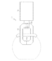
図2に示すように、落雷検出機器112は、電流リターンネットワーク102の一部の周囲に固定された巻線を備えたクランプオン型透磁性コア114と、フェライトコア114と通信する落雷検出回路116と、を含むことがある。クランプオン型フェライトコア114は、鉄、酸化第一鉄被覆セラミックまたはその他の材料のような、高透磁性材料の閉ループである。フェライトコア114は、取り外し可能であっても、または、電流リターンネットワーク102に取り付けられた常置機器であってもよい。
As shown in FIG. 2, the lightning
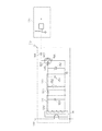
図3Aは、落雷検出回路116をさらに詳しく図解したものである。この図で示すように、回路116は、共振回路118、積分回路120、および、外部監視装置124に接続されたトランジスタ122とを含むことがある。共振回路118は、インダクタ126と、それと並列接続され、整流ダイオード130によって積分回路120と並列式に接続された第1コンデンサ128とを含むことがある。積分回路120は、並列接続されたレジスタ132と第2コンデンサ134とを含む。積分回路120は、トランジスタ122のゲート136に結合され、トランジスタソース138は接地へとつながる。トランジスタそれ自体122は、外部監視装置124と接地の間に電圧調整電流源を提供する、通常開放エンハンスメントモードn型金属酸化物半導体電界効果トランジスタ(n−MOSFET)として示されている。電磁干渉(EMI)低減要素は、回路116を損傷することがある電流帰還または電圧スパイクの可能性を低減させる、ツェナーダイオード142およびドレインダイオード144の形態で提供される。
FIG. 3A illustrates the lightning
一実施形態によれば、いくつかの落雷検出機器112は、落雷事象を捉えるよう、電流リターンネットワーク102の周囲に配置される。図2を参照すると、機器112は、ゾーン3領域内に配置されることが好ましいと思われるが、エンジンナセルの上面またはその近辺に、あるいは、航空機胴体に沿ってというように、ゾーン1または2領域内に配置されてもよい。
According to one embodiment, several
図2を参照して、落雷機器112の動作をさらに詳しく説明する。理解されるように、落雷事象がないとき、雷検出回路116は非通電状態のままとなる。しかしながら、落雷事象があるとき、回路は通電し、この事象を示す。この事象が示された後、回路は非通電状態にリセットされる。
The operation of the
航空機が落雷を受けたとき、1から50μs持続する電流スパイクが、電流リターンネットワーク102に運ばれる。電流リターンネットワーク102は、フェライトコア114の周囲に少なくとも1つのループを形成し、インダクタ126はいくつかのループをフェライトコア114の周囲に形成し、その結果、電流パルスが電流リターンネットワーク102を通り抜けるときにインダクタ126が補電流を発生させるよう、変圧器を形成する。
When the aircraft receives a lightning strike, a current spike lasting 1 to 50 μs is carried to the
共振回路118を形成するインダクタ126と第1コンデンサ128は、回路116を通電させる交流電流出力を作成することになる。共振回路118からの電流出力は、積分回路120に運ばれる前に、整流ダイオード130によって半波出力へと整流される。
The
積分回路120は、コンデンサが完全に充電されるよう、コンデンサ全体の電圧差を数秒間閾値レベルに維持することが好ましい第2コンデンサ134に、低速の充電および放電を提供する。積分回路は、外部監視装置124それ自体が事象によって乱された場合であっても、保持時間および雷表示が動作し続けるための自動リセットを提供する。
The integrating
第2コンデンサ134が、トランジスタ122のゲート閾値によって測定された閾値レベルであるとき、ソース138とドレイン140の間の回路は閉鎖され、電流は、外部監視装置124から接地へと、トランジスタを通って流れることが可能になる。外部監視装置124は、航空機内に取り付けられることがあり、また、回路116によって発生した電気的開放/接地ディスクリート信号を感知しその後これを障害または保守の表示ロジックに使用する開放/接地ディスクリートのような、標準的な航空機装置インターフェースであることもある、外部監視機器である。
When the
ツェナーダイオード142により、電圧が、トランジスタゲートからソースまで、トランジスタ122または他の構成部品を損傷しかねないレベルに達しないことが保証される。
ドレインダイオード144は、外部監視装置124とトランジスタ122の間に配置され、これにより電流が外部監視装置124からトランジスタを通って流れることが可能となる。この配置により、電流がトランジスタ122から外部監視装置124へと流れることは不可能となり、電流スパイクが接地する場合でも損傷を引き起こさないことが保証される。
The
上述の電気回路へのその他の改良も考慮される。図示されている実施形態によれば、回路は、通常は開放しており、ゲート136に正電圧が印加されたときに閉鎖して電流がソース138とドレイン140との間を流れることを可能にする、n−MOSFETトランジスタ122を含む。しかしながら、通常閉鎖デプレッションモードMOSFETは、通常開放エンハンスメントモードトランジスタ122を代替できると考慮される。
Other improvements to the electrical circuit described above are also contemplated. According to the illustrated embodiment, the circuit is normally open and closes when a positive voltage is applied to
整流ダイオード130は、タンク回路と積分回路との間に直列接続された単一ダイオードとして示される。この半波整流器は、共振回路118によって生成された共振波形の半分しか通過させず、したがって、通過するエネルギーの量は低減する。しかしながら、このダイオードは、追加エネルギーが必要な場合は、ダイオードブリッジまたは他の形式の整流器のような全波整流器と置換できる。
The rectifying
回路116は、ツェナーダイオード142およびドレインダイオード144のようなEMI防護要素を含むとも、すでに説明されている。これらの要素は、トランジスタ122(ツェナーダイオード142)の電圧過負荷、または、外部監視装置124への電流帰還に対する防護を提供するために含まれるものである。しかしながら、これらの要素は回路の動作のために必要なものではなく、省略されてもよい。これらの防護要素の代わりに、またはこれらの防護要素に加えて、代替防護要素が含まれることもある。
共振回路118は落雷波形に基づいて交流電流を提供するが、積分回路120に電圧差動を提供することは必ずしも必要ではない。電流リターンネットワーク102内の電流スパイクは、トランジスタ122を駆動するのに使用される可能性があるインダクタ126において、対応する電圧スパイクを発生させると考えられる。しかしながら、共振回路118は、例えば降水空電ノイズや他の無線周波数(RF)ノイズのようなRFノイズに対する回路の感度を低減させる、帯域制限関数を提供するという、さらなる利点を提供する。
Although the
単一の有線接続を備えた受動素子(電流リターンネットワーク112)として、検出回路116に関して組み込み試験を追加することは、適切でないことがある。この試験機能は、落雷をシミュレーションするために回路116にパルスを提供することができる、フェライトコア114上の第2の巻線の組を追加することによって、達成することが可能である。これは、システムが正しく機能していると判断するための、効果的な試験としての役割を果たすと考えられる。
Adding a built-in test for the
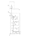
図1を参照して説明されたように、電流リターンネットワーク102は、航空機の電気的構成要素のための接地としての役割を果たすことがある。しかしながら、落雷から電流リターンネットワーク102を通るサージは、多くの場合、航空機の様々なシステムに電気的不具合をもたらすものとなる。したがって、電流リターンネットワーク102を落雷検出回路116の接地として使用することは、望ましくないかもしれない。図3Aに示される一実施形態によれば、外部監視装置124は電流リターンネットワーク102のような接地に接続され、また、落雷検出回路116は1つの独立した接地に接続される。図3Bは、落雷検出回路116と外部監視装置が、1つの独立した接地であることもある共通の接地146を共有する、代替的な配置構成を示す。
As described with reference to FIG. 1, the
ここで開示される方法および装置の形態が、開示された落雷検出装置および方法の好ましい態様を構成する一方で、本発明の範囲から逸脱せずに、その他の方法および装置の形態を用いることができる。
また、本願は以下に記載する態様を含む。
(態様1)
落雷を検出するための電源内蔵型システムであって、
落雷を受けかつ消散させる電流リターンネットワークと、
前記電流リターンネットワークと通信する変圧器を有しかつ交流電気出力を提供する共振回路と、
前記交流電気出力を直流電気出力へと整流するための整流器と、
前記直流電気出力を受け取ると電圧閾値まで昇圧する低速積分器と、また、
障害監視ソフトウェアと信号をやりとりするための前記低速積分器よって発動する出力トランジスタと、を備えるシステム。
(態様2)
前記電流リターンネットワークは航空機内部の導電性経路を備える、態様1に記載のシステム。
(態様3)
前記共振回路はインダクタとコンデンサとを含む、態様2に記載のシステム。
(態様4)
前記積分器はコンデンサを備える、態様3に記載のシステム。
(態様5)
前記コンデンサは完全に充電されている、態様4に記載のシステム。
(態様6)
電流リターンネットワーク内の電圧スパイクを検出する方法であって、前記方法は、
前記電流リターンネットワークとの誘導通信におけるフェライトコアを提供するステップと、
前記フェライトコア、積分回路およびトランジスタとの誘導通信における共振回路を有する検出回路を提供するステップと、
電流スパイクを前記電流リターンネットワークを通じて提供するステップと、
前記共振回路を誘導的に通電することで交流電流を提供するステップと、
前記電流を整流するステップと、
前記積分回路内のコンデンサを閾値電圧レベルまで充電するステップと、
前記閾値電圧レベルに達したときに前記トランジスタの状態を変えるステップと、また、
前記状態の変化を前記電圧スパイクの表示として検出するステップと、を備える、方法。
(態様7)
前記整流は半波整流器によるものである、態様6に記載の方法。
(態様8)
前記共振回路はインダクタと第1コンデンサとを備える、態様6に記載の方法。
(態様9)
前記電流リターンネットワーク、前記インダクタ、および前記フェライトコアは変圧器を備える、態様8に記載の方法。
(態様10)
前記フェライトコアは、前記電流リターンネットワークから選択的に取り外し可能である、態様9に記載の方法。
(態様11)
前記フェライトコアを前記電流リターンネットワークに取り付けるステップをさらに備える、態様10に記載の方法。
(態様12)
前記トランジスタは通常開放n型金属酸化物半導体電界効果トランジスタ(n−MOSFET)である、態様6に記載の方法。
(態様13)
遠隔障害モニタを提供するステップをさらに含む、態様12に記載の方法。
(態様14)
前記遠隔障害モニタからトランジスタを通る電流の流れが、状態の変化を検出するために使用される、態様13に記載の方法。
(態様15)
前記状態の変化が一旦検出されたときに前記閾値電圧をブリードオフするためのレジスタをさらに備える、態様14に記載の方法。
While the method and apparatus forms disclosed herein constitute preferred embodiments of the disclosed lightning strike detection apparatus and method, other method and apparatus forms may be used without departing from the scope of the present invention. it can.
Moreover, this application contains the aspect described below.
(Aspect 1)
A system with a built-in power supply for detecting lightning strikes,
A current return network that receives and dissipates lightning, and
A resonant circuit having a transformer in communication with the current return network and providing an alternating electrical output;
A rectifier for rectifying the AC electrical output to a DC electrical output;
A slow integrator that boosts to a voltage threshold upon receipt of the DC electrical output; and
An output transistor that is activated by the low-speed integrator for exchanging signals with fault monitoring software.
(Aspect 2)
The system of aspect 1, wherein the current return network comprises a conductive path inside an aircraft.
(Aspect 3)
The system of aspect 2, wherein the resonant circuit includes an inductor and a capacitor.
(Aspect 4)
The system of aspect 3, wherein the integrator comprises a capacitor.
(Aspect 5)
The system of embodiment 4, wherein the capacitor is fully charged.
(Aspect 6)
A method for detecting voltage spikes in a current return network, the method comprising:
Providing a ferrite core in inductive communication with the current return network;
Providing a detection circuit having a resonant circuit in inductive communication with the ferrite core, an integrating circuit and a transistor;
Providing a current spike through the current return network;
Providing an alternating current by inductively energizing the resonant circuit;
Rectifying the current;
Charging a capacitor in the integrating circuit to a threshold voltage level;
Changing the state of the transistor when the threshold voltage level is reached;
Detecting the change in state as an indication of the voltage spike.
(Aspect 7)
The method of aspect 6, wherein the rectification is by a half-wave rectifier.
(Aspect 8)
The method of aspect 6, wherein the resonant circuit comprises an inductor and a first capacitor.
(Aspect 9)
9. The method of aspect 8, wherein the current return network, the inductor, and the ferrite core comprise a transformer.
(Aspect 10)
The method of aspect 9, wherein the ferrite core is selectively removable from the current return network.
(Aspect 11)
The method of aspect 10, further comprising attaching the ferrite core to the current return network.
(Aspect 12)
The method according to aspect 6, wherein the transistor is a normally open n-type metal oxide semiconductor field effect transistor (n-MOSFET).
(Aspect 13)
The method of aspect 12, further comprising providing a remote fault monitor.
(Aspect 14)
A method according to aspect 13, wherein the flow of current through a transistor from the remote fault monitor is used to detect a change in state.
(Aspect 15)
15. The method of aspect 14, further comprising a register for bleed-off the threshold voltage once the change in state is detected.
100 航空機
102 電流リターンネットワーク
104 縦方向の導電性要素
106 横方向の導電性要素
108 通電経路
112 落雷検出機器
114 クランプオン型透磁性コア(フェライトコア)
116 落雷検出回路
118 共振回路
120 積分回路
122 トランジスタ
124 外部監視装置
126 インダクタ
128 第1コンデンサ
130 整流ダイオード
132 レジスタ
134 第2コンデンサ
136 ゲート
138 トランジスタソース
140 ドレイン
142 ツェナーダイオード
144 ドレインダイオード
146 接地
DESCRIPTION OF
116 Lightning
Claims (7)
落雷を受けかつ消散させる電流リターンネットワーク(102)と、
前記電流リターンネットワーク(102)と通信する変圧器を有しかつ交流電気出力を提供する共振回路(118)と、
前記交流電気出力を直流電気出力へと整流するための整流器(130)と、
第2のコンデンサ(134)を含み、前記直流電気出力を受け取ると電圧閾値まで昇圧する積分回路(120)と、
前記電圧閾値に達したときに前記積分回路(120)よって状態を変えるようになっており、障害監視ソフトウェアと信号をやりとりする出力トランジスタ(122)と、
外部監視装置(124)であって、ダイオード(144)により前記出力トランジスタ(122)に接続されることで、当該外部監視装置(124)から前記出力トランジスタ(122)に電流が流れる外部監視装置(124)と、を備えるシステム。 A system with a built-in power supply for detecting lightning strikes,
A current return network (102) that receives and dissipates lightning strikes;
A resonant circuit (118) having a transformer in communication with the current return network (102) and providing an alternating electrical output;
A rectifier (130) for rectifying the AC electrical output to a DC electrical output;
An integrating circuit (120) including a second capacitor (134) and boosting to a voltage threshold upon receipt of the DC electrical output ;
Being adapted to vary the integration circuit (120) Thus state when reaching the voltage threshold, and you exchanging fault monitoring software and the signal output transistors (122),
An external monitoring device (124), which is connected to the output transistor (122) by a diode (144) so that current flows from the external monitoring device (124) to the output transistor (122). 124) .
前記電流リターンネットワーク(102)と誘導通信するフェライトコア(114)を提供するステップと、
前記フェライトコア(114)、積分回路(120)およびトランジスタ(122)と誘導通信する共振回路(118)を有する検出回路(116)を提供するステップと、
外部監視装置(124)であって、ダイオード(144)により前記トランジスタ(122)に接続されることで、当該外部監視装置(124)から前記トランジスタ(122)に電流が流れる外部監視装置(124)を提供するステップと、
前記電流リターンネットワーク(102)内の電流スパイクにより前記共振回路(118)を誘導的に通電することで交流電流を提供するステップと、
整流器(130)により前記交流電流を整流するステップと、
前記整流された電流により前記積分回路(120)内の第2のコンデンサ(134)を閾値電圧レベルまで充電するステップと、
前記閾値電圧レベルに達したときに前記トランジスタの状態を変えるステップと、また、
前記状態の変化を前記落雷の表示として検出するステップと、を備える、方法。 A method of detecting lightning strikes in an aircraft current return network (102) comprising:
Providing a ferrite core (114) for inductive communication with said current return network (102),
Providing said ferrite cores (114), an integration circuit (120) and the transistor (122) and inductive detection circuit having a resonant circuit (118) for communicating (116),
An external monitoring device (124), which is connected to the transistor (122) by a diode (144), whereby a current flows from the external monitoring device (124) to the transistor (122). Providing steps, and
Providing an alternating current by inductively energizing the resonant circuit (118) with a current spike in the current return network (102) ;
Rectifying the alternating current with a rectifier (130) ;
Charging the second capacitor ( 134 ) in the integrator circuit (120) with the rectified current to a threshold voltage level;
Changing the state of the transistor when the threshold voltage level is reached;
Detecting the change in state as an indication of the lightning strike .
Applications Claiming Priority (3)
| Application Number | Priority Date | Filing Date | Title |
|---|---|---|---|
| US13/280,915 | 2011-10-25 | ||
| US13/280,915 US8841898B2 (en) | 2011-10-25 | 2011-10-25 | Method and apparatus for detecting a lightning strike |
| PCT/US2012/057151 WO2013062706A1 (en) | 2011-10-25 | 2012-09-25 | Method and apparatus for detecting a lightning strike |
Publications (3)
| Publication Number | Publication Date |
|---|---|
| JP2014534437A JP2014534437A (en) | 2014-12-18 |
| JP2014534437A5 JP2014534437A5 (en) | 2015-08-27 |
| JP6076366B2 true JP6076366B2 (en) | 2017-02-08 |
Family
ID=47215717
Family Applications (1)
| Application Number | Title | Priority Date | Filing Date |
|---|---|---|---|
| JP2014538800A Active JP6076366B2 (en) | 2011-10-25 | 2012-09-25 | Method and apparatus for detecting lightning strikes |
Country Status (7)
| Country | Link |
|---|---|
| US (1) | US8841898B2 (en) |
| EP (2) | EP2771702B1 (en) |
| JP (1) | JP6076366B2 (en) |
| BR (1) | BR112014008987B1 (en) |
| CA (1) | CA2844412C (en) |
| RU (1) | RU2611109C2 (en) |
| WO (1) | WO2013062706A1 (en) |
Families Citing this family (16)
| Publication number | Priority date | Publication date | Assignee | Title |
|---|---|---|---|---|
| US20170307672A9 (en) * | 2013-01-29 | 2017-10-26 | Smart Drilling And Completion, Inc. | Stable grounding system to avoid catastrophic electrical failures in fiber-reinforced composite aircraft |
| US9488609B2 (en) * | 2014-02-06 | 2016-11-08 | The Boeing Company | Determination of anisotropic conduction characteristics |
| US9748759B1 (en) | 2014-05-09 | 2017-08-29 | Donald J. Bergeron | Lightning electromagnetic pulse (LEMP) detector and isolation device |
| DE102016000930B4 (en) * | 2015-09-04 | 2024-07-18 | Dehn Se | Method for recording lightning current parameters at wind turbines |
| JP6562354B2 (en) * | 2015-11-25 | 2019-08-21 | パナソニックIpマネジメント株式会社 | Power supply device and lighting fixture |
| CN105527515A (en) * | 2015-12-02 | 2016-04-27 | 无锡拓能自动化科技有限公司 | Mutual inductance self-powered monitoring device for high voltage switch cabinet |
| CN108205076A (en) * | 2018-03-06 | 2018-06-26 | 苏宇宁 | Lightning protection potential difference test method |
| DE102018114356B4 (en) * | 2018-06-15 | 2024-04-04 | Airbus Operations Gmbh | Aircraft with a fuselage, a wing and a tail unit as well as a surface structure containing a lightning protection device |
| RU2714526C1 (en) * | 2019-06-19 | 2020-02-18 | Общество с ограниченной ответственностью "Челэнергоприбор" | Current pulse counter through overvoltage limiter |
| US11420765B2 (en) * | 2020-03-26 | 2022-08-23 | Aerion Intellectual Property Management Corporation | Aircraft fuselage with internal current return network |
| TWI758831B (en) * | 2020-08-21 | 2022-03-21 | 安雷科技股份有限公司 | Lightning strike counter and lightning strike counting method |
| WO2022176138A1 (en) * | 2021-02-19 | 2022-08-25 | 三菱電機株式会社 | Lightning strike determination control device, power supply system, and lightning strike determination control method |
| US11879931B2 (en) * | 2021-08-25 | 2024-01-23 | Hamilton Sundstrand Corporation | Circuit testing and diagnosis |
| JP2024134821A (en) * | 2023-03-22 | 2024-10-04 | エイブリック株式会社 | Current sensing circuit. |
| US20250314685A1 (en) * | 2024-04-05 | 2025-10-09 | Honeywell International Inc. | Detector and method for non-intrusively detecting electromagnetic interference |
| CN118312932B (en) * | 2024-06-11 | 2024-08-23 | 华南理工大学 | Analysis method and system for association relation between waveform parameters of back-striking current and injection energy difference |
Family Cites Families (32)
| Publication number | Priority date | Publication date | Assignee | Title |
|---|---|---|---|---|
| US2114865A (en) * | 1937-02-06 | 1938-04-19 | Gen Electric | Peak alternating current measuring apparatus |
| US3889185A (en) | 1974-04-15 | 1975-06-10 | Nasa | Lightning current measuring systems |
| JPS6146613A (en) | 1984-08-10 | 1986-03-06 | Nec Corp | Level detecting circuit |
| FR2624319B1 (en) | 1987-12-07 | 1990-05-04 | Lewiner Jacques | ION EMISSION LIGHTNING PROTECTION DEVICES |
| FR2685532B1 (en) | 1991-12-20 | 1994-12-30 | Soule Sa | SURGE PROTECTOR WITH IMPROVED MECHANICAL PROPERTIES. |
| JPH06281688A (en) * | 1993-03-26 | 1994-10-07 | Ngk Insulators Ltd | Displaying device for accident of transmission and distribution cable way |
| FR2713345B1 (en) | 1993-12-03 | 1996-01-05 | Alcatel Cable | Impulse energy measurement device. |
| FR2718898B1 (en) | 1994-04-18 | 1996-06-28 | Jacques Lewiner | Method and device for monitoring lightning protection equipment. |
| US5446431A (en) * | 1994-04-28 | 1995-08-29 | Square D Company | Ground fault module conductors and base therefor |
| NL1001035C2 (en) | 1995-08-23 | 1997-02-25 | Heide Beheer B V V D | Device for recording lightning strikes. |
| US6114814A (en) * | 1998-12-11 | 2000-09-05 | Monolithic Power Systems, Inc. | Apparatus for controlling a discharge lamp in a backlighted display |
| JP3266884B2 (en) * | 1999-10-15 | 2002-03-18 | 義宏 平川 | Lightning detector |
| JP4748404B2 (en) * | 2000-07-31 | 2011-08-17 | 中部電力株式会社 | Current detection device and ground fault display device |
| US6924566B2 (en) * | 2001-08-08 | 2005-08-02 | Adtran, Inc. | Method for assuring start-up of span-powered telecommunication systems |
| JP2003059614A (en) | 2001-08-10 | 2003-02-28 | Mitsubishi Electric Corp | Lightning arrester operation detector |
| US7245511B2 (en) * | 2004-08-25 | 2007-07-17 | Itron, Inc. | Resistor dropper power supply with surge protection |
| US7890891B2 (en) * | 2005-07-11 | 2011-02-15 | Peregrine Semiconductor Corporation | Method and apparatus improving gate oxide reliability by controlling accumulated charge |
| US7193428B1 (en) * | 2006-01-19 | 2007-03-20 | Veris Industries, Llc | Low threshold current switch |
| US7525785B2 (en) * | 2006-12-14 | 2009-04-28 | The Boeing Company | Lightning strike protection method and apparatus |
| FR2911440B1 (en) * | 2007-01-12 | 2009-04-10 | Abb France | DEVICE AND METHOD FOR MEASURING LIGHTNING CURRENT |
| RU2339547C9 (en) * | 2007-03-27 | 2009-01-20 | Федеральное государственное унитарное предприятие "Летно-исследовательский институт имени М.М. Громова" | Automated high-intelligent system for aircraft flight safety providing |
| US7417843B1 (en) * | 2007-03-28 | 2008-08-26 | Benjamin P. Fowler | System and method of protecting metallic structures from lightning strikes |
| CA2609611A1 (en) * | 2007-09-10 | 2009-03-10 | Veris Industries, Llc | Split core status indicator |
| US7714743B1 (en) | 2007-09-14 | 2010-05-11 | Rockwell Collins, Inc. | Aircraft lightning strike detector |
| GB2458152B (en) * | 2008-03-07 | 2010-09-29 | Insensys Ltd | Lightning detection |
| US8179653B2 (en) * | 2008-07-17 | 2012-05-15 | Advanced Protection Technologies, Inc. | Multiple operating voltage electrical surge protection apparatus |
| RU2395434C2 (en) * | 2008-08-06 | 2010-07-27 | Федеральное государственное унитарное предприятие "Лётно-исследовательский институт имени М.М. Громова" | Aircraft lightning protection device |
| FR2936063B1 (en) | 2008-09-17 | 2010-12-10 | Indelec | DEVICE FOR DETECTING PHYSICAL EVENTS IN AN ELECTRICAL CONDUCTOR. |
| US8031458B2 (en) | 2008-11-24 | 2011-10-04 | The Boeing Company | Current return network |
| US8005617B2 (en) * | 2010-11-29 | 2011-08-23 | General Electric Company | System and method for detecting lightning strikes likely to affect a condition of a structure |
| US20120154021A1 (en) * | 2010-12-20 | 2012-06-21 | Amita Chandrakant Patil | Integrated circuit and method of fabricating same |
| TWI440394B (en) * | 2011-04-20 | 2014-06-01 | Univ Nat Chi Nan | Optical power compensation circuit and device, detection module |
-
2011
- 2011-10-25 US US13/280,915 patent/US8841898B2/en active Active
-
2012
- 2012-09-25 EP EP12788323.9A patent/EP2771702B1/en active Active
- 2012-09-25 WO PCT/US2012/057151 patent/WO2013062706A1/en not_active Ceased
- 2012-09-25 JP JP2014538800A patent/JP6076366B2/en active Active
- 2012-09-25 EP EP18199445.0A patent/EP3444621B1/en active Active
- 2012-09-25 BR BR112014008987-6A patent/BR112014008987B1/en active IP Right Grant
- 2012-09-25 CA CA2844412A patent/CA2844412C/en active Active
- 2012-09-25 RU RU2014116073A patent/RU2611109C2/en active
Also Published As
| Publication number | Publication date |
|---|---|
| CA2844412C (en) | 2017-10-24 |
| EP2771702A1 (en) | 2014-09-03 |
| BR112014008987B1 (en) | 2021-01-19 |
| EP3444621B1 (en) | 2020-03-18 |
| EP2771702B1 (en) | 2018-11-21 |
| RU2611109C2 (en) | 2017-02-21 |
| RU2014116073A (en) | 2015-12-10 |
| CA2844412A1 (en) | 2013-05-02 |
| US8841898B2 (en) | 2014-09-23 |
| JP2014534437A (en) | 2014-12-18 |
| WO2013062706A1 (en) | 2013-05-02 |
| EP3444621A1 (en) | 2019-02-20 |
| US20130099772A1 (en) | 2013-04-25 |
| BR112014008987A2 (en) | 2017-05-02 |
Similar Documents
| Publication | Publication Date | Title |
|---|---|---|
| JP6076366B2 (en) | Method and apparatus for detecting lightning strikes | |
| US20120019962A1 (en) | Sensing and Control Electronics for a Power Grid Protection System | |
| JP2014534437A5 (en) | ||
| KR101535950B1 (en) | Contact failure detection device by counting pulses | |
| CN105591366A (en) | Frequency converter and method for identifying and blocking a fault current in a frequency converter | |
| CN108292838B (en) | Type B or B+ differential protection device including two parallel and competing modules | |
| JP2023522276A (en) | Non-isolated drivers for LED lighting | |
| JP2010042784A (en) | Direct current high-voltage grounding relay and circuit for preventing malfunction of relay | |
| CN101404453A (en) | Anti-interference switch stabilized voltage supply | |
| CN106019194A (en) | Test method for electric leakage detection circuit | |
| KR101033699B1 (en) | High frequency malfunction prevention circuit of earth leakage breaker | |
| JP7142921B2 (en) | Surge current measuring device | |
| CN207381953U (en) | Arc, earth leakage | |
| CN112398105A (en) | Back-up protector control system of surge protector and operation method thereof | |
| CN104767190B (en) | Monitor the warning circuit of arrester deterioration | |
| KR20160061565A (en) | Limiter device capable of contact failure detection having delay circuit | |
| CN104297587B (en) | A kind of direct-current transmission converter valve lightning arrester monitoring device and monitoring method | |
| JP5744602B2 (en) | Current transformer protection device | |
| CN106849044B (en) | A kind of invariable power overvoltage intelligence short-circuit protector | |
| CN102881437A (en) | Current transformer for detecting aftercurrent, and aftercurrent protection device | |
| JP5851207B2 (en) | Ground fault detection device | |
| JP6784541B2 (en) | Ground fault detector | |
| CN204258281U (en) | Overvoltage bypass checkout gear | |
| AU2010355287B2 (en) | Foreign track current suppression system and method | |
| CN204243377U (en) | A kind of novel light-emitting earth connection |
Legal Events
| Date | Code | Title | Description |
|---|---|---|---|
| A711 | Notification of change in applicant |
Free format text: JAPANESE INTERMEDIATE CODE: A711 Effective date: 20141010 |
|
| A521 | Request for written amendment filed |
Free format text: JAPANESE INTERMEDIATE CODE: A821 Effective date: 20141010 |
|
| A521 | Request for written amendment filed |
Free format text: JAPANESE INTERMEDIATE CODE: A523 Effective date: 20150707 |
|
| A621 | Written request for application examination |
Free format text: JAPANESE INTERMEDIATE CODE: A621 Effective date: 20150707 |
|
| A977 | Report on retrieval |
Free format text: JAPANESE INTERMEDIATE CODE: A971007 Effective date: 20160519 |
|
| A131 | Notification of reasons for refusal |
Free format text: JAPANESE INTERMEDIATE CODE: A131 Effective date: 20160531 |
|
| A521 | Request for written amendment filed |
Free format text: JAPANESE INTERMEDIATE CODE: A523 Effective date: 20160830 |
|
| TRDD | Decision of grant or rejection written | ||
| A01 | Written decision to grant a patent or to grant a registration (utility model) |
Free format text: JAPANESE INTERMEDIATE CODE: A01 Effective date: 20161213 |
|
| A61 | First payment of annual fees (during grant procedure) |
Free format text: JAPANESE INTERMEDIATE CODE: A61 Effective date: 20170110 |
|
| R150 | Certificate of patent or registration of utility model |
Ref document number: 6076366 Country of ref document: JP Free format text: JAPANESE INTERMEDIATE CODE: R150 |
|
| R250 | Receipt of annual fees |
Free format text: JAPANESE INTERMEDIATE CODE: R250 |
|
| R250 | Receipt of annual fees |
Free format text: JAPANESE INTERMEDIATE CODE: R250 |
|
| R250 | Receipt of annual fees |
Free format text: JAPANESE INTERMEDIATE CODE: R250 |
|
| R250 | Receipt of annual fees |
Free format text: JAPANESE INTERMEDIATE CODE: R250 |
|
| R250 | Receipt of annual fees |
Free format text: JAPANESE INTERMEDIATE CODE: R250 |
|
| R250 | Receipt of annual fees |
Free format text: JAPANESE INTERMEDIATE CODE: R250 |
|
| R250 | Receipt of annual fees |
Free format text: JAPANESE INTERMEDIATE CODE: R250 |