EP2771702B1 - Method and apparatus for detecting a lightning strike - Google Patents
Method and apparatus for detecting a lightning strike Download PDFInfo
- Publication number
- EP2771702B1 EP2771702B1 EP12788323.9A EP12788323A EP2771702B1 EP 2771702 B1 EP2771702 B1 EP 2771702B1 EP 12788323 A EP12788323 A EP 12788323A EP 2771702 B1 EP2771702 B1 EP 2771702B1
- Authority
- EP
- European Patent Office
- Prior art keywords
- current
- transistor
- return network
- current return
- circuit
- Prior art date
- Legal status (The legal status is an assumption and is not a legal conclusion. Google has not performed a legal analysis and makes no representation as to the accuracy of the status listed.)
- Active
Links
- 238000000034 method Methods 0.000 title claims description 15
- 238000012544 monitoring process Methods 0.000 claims description 19
- 239000003990 capacitor Substances 0.000 claims description 16
- 238000001514 detection method Methods 0.000 claims description 16
- 229910000859 α-Fe Inorganic materials 0.000 claims description 16
- 230000008859 change Effects 0.000 claims description 11
- 238000004891 communication Methods 0.000 claims description 8
- 230000001939 inductive effect Effects 0.000 claims description 5
- 230000001960 triggered effect Effects 0.000 claims description 2
- 239000002131 composite material Substances 0.000 description 3
- 230000006870 function Effects 0.000 description 3
- 238000012423 maintenance Methods 0.000 description 3
- 238000012360 testing method Methods 0.000 description 3
- 238000004804 winding Methods 0.000 description 3
- XEEYBQQBJWHFJM-UHFFFAOYSA-N Iron Chemical compound [Fe] XEEYBQQBJWHFJM-UHFFFAOYSA-N 0.000 description 2
- UQSXHKLRYXJYBZ-UHFFFAOYSA-N Iron oxide Chemical compound [Fe]=O UQSXHKLRYXJYBZ-UHFFFAOYSA-N 0.000 description 2
- 230000008901 benefit Effects 0.000 description 2
- 239000004020 conductor Substances 0.000 description 2
- 230000005669 field effect Effects 0.000 description 2
- 239000000463 material Substances 0.000 description 2
- 239000002184 metal Substances 0.000 description 2
- 229910052751 metal Inorganic materials 0.000 description 2
- 229910044991 metal oxide Inorganic materials 0.000 description 2
- 150000004706 metal oxides Chemical class 0.000 description 2
- 238000012545 processing Methods 0.000 description 2
- 230000001681 protective effect Effects 0.000 description 2
- 239000004065 semiconductor Substances 0.000 description 2
- 230000000740 bleeding effect Effects 0.000 description 1
- 239000000919 ceramic Substances 0.000 description 1
- 230000000295 complement effect Effects 0.000 description 1
- 238000012790 confirmation Methods 0.000 description 1
- 238000010276 construction Methods 0.000 description 1
- 230000000694 effects Effects 0.000 description 1
- 229910052742 iron Inorganic materials 0.000 description 1
- 230000002045 lasting effect Effects 0.000 description 1
- 230000000116 mitigating effect Effects 0.000 description 1
- 230000037361 pathway Effects 0.000 description 1
- 230000035699 permeability Effects 0.000 description 1
- 238000001556 precipitation Methods 0.000 description 1
- 230000002265 prevention Effects 0.000 description 1
- 238000011084 recovery Methods 0.000 description 1
- 230000009467 reduction Effects 0.000 description 1
- 230000035945 sensitivity Effects 0.000 description 1
- 230000011664 signaling Effects 0.000 description 1
- 230000003068 static effect Effects 0.000 description 1
- 230000001131 transforming effect Effects 0.000 description 1
- 230000000007 visual effect Effects 0.000 description 1
Images
Classifications
-
- G—PHYSICS
- G01—MEASURING; TESTING
- G01R—MEASURING ELECTRIC VARIABLES; MEASURING MAGNETIC VARIABLES
- G01R15/00—Details of measuring arrangements of the types provided for in groups G01R17/00 - G01R29/00, G01R33/00 - G01R33/26 or G01R35/00
- G01R15/14—Adaptations providing voltage or current isolation, e.g. for high-voltage or high-current networks
- G01R15/18—Adaptations providing voltage or current isolation, e.g. for high-voltage or high-current networks using inductive devices, e.g. transformers
- G01R15/183—Adaptations providing voltage or current isolation, e.g. for high-voltage or high-current networks using inductive devices, e.g. transformers using transformers with a magnetic core
-
- B—PERFORMING OPERATIONS; TRANSPORTING
- B64—AIRCRAFT; AVIATION; COSMONAUTICS
- B64D—EQUIPMENT FOR FITTING IN OR TO AIRCRAFT; FLIGHT SUITS; PARACHUTES; ARRANGEMENTS OR MOUNTING OF POWER PLANTS OR PROPULSION TRANSMISSIONS IN AIRCRAFT
- B64D45/00—Aircraft indicators or protectors not otherwise provided for
- B64D45/02—Lightning protectors; Static dischargers
-
- G—PHYSICS
- G01—MEASURING; TESTING
- G01R—MEASURING ELECTRIC VARIABLES; MEASURING MAGNETIC VARIABLES
- G01R19/00—Arrangements for measuring currents or voltages or for indicating presence or sign thereof
- G01R19/165—Indicating that current or voltage is either above or below a predetermined value or within or outside a predetermined range of values
- G01R19/16504—Indicating that current or voltage is either above or below a predetermined value or within or outside a predetermined range of values characterised by the components employed
- G01R19/16519—Indicating that current or voltage is either above or below a predetermined value or within or outside a predetermined range of values characterised by the components employed using FET's
-
- G—PHYSICS
- G01—MEASURING; TESTING
- G01R—MEASURING ELECTRIC VARIABLES; MEASURING MAGNETIC VARIABLES
- G01R31/00—Arrangements for testing electric properties; Arrangements for locating electric faults; Arrangements for electrical testing characterised by what is being tested not provided for elsewhere
- G01R31/005—Testing of electric installations on transport means
- G01R31/008—Testing of electric installations on transport means on air- or spacecraft, railway rolling stock or sea-going vessels
-
- H—ELECTRICITY
- H02—GENERATION; CONVERSION OR DISTRIBUTION OF ELECTRIC POWER
- H02G—INSTALLATION OF ELECTRIC CABLES OR LINES, OR OF COMBINED OPTICAL AND ELECTRIC CABLES OR LINES
- H02G13/00—Installations of lightning conductors; Fastening thereof to supporting structure
-
- H—ELECTRICITY
- H02—GENERATION; CONVERSION OR DISTRIBUTION OF ELECTRIC POWER
- H02H—EMERGENCY PROTECTIVE CIRCUIT ARRANGEMENTS
- H02H3/00—Emergency protective circuit arrangements for automatic disconnection directly responsive to an undesired change from normal electric working condition with or without subsequent reconnection ; integrated protection
- H02H3/20—Emergency protective circuit arrangements for automatic disconnection directly responsive to an undesired change from normal electric working condition with or without subsequent reconnection ; integrated protection responsive to excess voltage
- H02H3/22—Emergency protective circuit arrangements for automatic disconnection directly responsive to an undesired change from normal electric working condition with or without subsequent reconnection ; integrated protection responsive to excess voltage of short duration, e.g. lightning
-
- G—PHYSICS
- G01—MEASURING; TESTING
- G01R—MEASURING ELECTRIC VARIABLES; MEASURING MAGNETIC VARIABLES
- G01R29/00—Arrangements for measuring or indicating electric quantities not covered by groups G01R19/00 - G01R27/00
- G01R29/08—Measuring electromagnetic field characteristics
- G01R29/0807—Measuring electromagnetic field characteristics characterised by the application
- G01R29/0814—Field measurements related to measuring influence on or from apparatus, components or humans, e.g. in ESD, EMI, EMC, EMP testing, measuring radiation leakage; detecting presence of micro- or radiowave emitters; dosimetry; testing shielding; measurements related to lightning
- G01R29/0842—Measurements related to lightning, e.g. measuring electric disturbances, warning systems
-
- Y—GENERAL TAGGING OF NEW TECHNOLOGICAL DEVELOPMENTS; GENERAL TAGGING OF CROSS-SECTIONAL TECHNOLOGIES SPANNING OVER SEVERAL SECTIONS OF THE IPC; TECHNICAL SUBJECTS COVERED BY FORMER USPC CROSS-REFERENCE ART COLLECTIONS [XRACs] AND DIGESTS
- Y02—TECHNOLOGIES OR APPLICATIONS FOR MITIGATION OR ADAPTATION AGAINST CLIMATE CHANGE
- Y02T—CLIMATE CHANGE MITIGATION TECHNOLOGIES RELATED TO TRANSPORTATION
- Y02T50/00—Aeronautics or air transport
- Y02T50/50—On board measures aiming to increase energy efficiency
Definitions
- the current disclosure relates to a current spike detector and more specifically to an electrical circuit for detecting lightning strikes in aircraft.
- Lightning strikes on aircraft are relatively rare events, yet occur with sufficient frequency and are sufficiently damaging to mechanical and electrical systems that lightning strike prevention and mitigation are important components within an aircraft.
- Some of these electrical system warnings may be so-called "nuisance warnings" that occur due to the system resetting because of the lightning strike rather than any problem with the system.
- these systems will still require manual resetting by a maintenance worker to reset the warnings and determine if the fault was due to the li lightning strike event or a problem in the affected system.
- EP 0549432A discloses a surge arrester comprising: a varistor stack, two contact pieces made of an electrically conductive material and placed respectively on the ends of the varistor stack, and an envelope of composite material surrounding the varistor stack.
- the surge arrester further includes a fault signalling device to signal the passage of a leakage current through the surge arrester.
- FR 293063 discloses a device having a processing unit, including a counting unit for counting physical events detected by a sensor, and a storing module for storing the physical events in a memory.
- the sensor comprises a detection unit for detecting information relative to presence of electric current in an electric cable and transmitting the information to the processing unit.
- the sensor comprises a recovery unit e.g. winding, for recovering energy transmitted by the current detected in the cable and for supplying power to the modules.
- a self-powered system for detecting a lightning strike including a current return network receiving and dissipating the lightning strike, a resonant circuit having a transformer in communication with the current return network and providing an alternating electrical output, a rectifier for rectifying the alternating electrical output into a direct electrical output, an integrator circuit that builds to a voltage threshold when the direct electrical output is received, including a second capacitor; an output transistor triggered to change state by the integrator circuit when the voltage threshold is reached; and external monitoring equipment connected to the output transistor by a diode such that current flows from the external monitoring equipment to the output transistor.
- the current return network includes an electrically conductive path within an aircraft.
- the resonant circuit includes an inductor and a first capacitor. Preferably the capacitor is completely charged.
- a method of detecting a lightning strike in a current return network includes the steps of providing a ferrite core in inductive communication with the current return network, providing a detection circuit having a resonant circuit in inductive communication with the ferrite core, an integrator circuit, and a transistor, inductively energizing the resonant circuit by a current spike in the current return network to provide an alternating current, rectifying the alternating current by a rectifier, charging a second capacitor in the integrator circuit by the rectified current to a threshold voltage level, changing the transistor's state when the threshold voltage level is reached, and detecting the change in state as indicative of the lightning strike, wherein the resonant circuit comprises an inductor and a first capacitor.
- the rectification is by means of a half-wave rectifier.
- the current return network, the inductor, and the ferrite core form a transformer.
- the ferrite core is selectively removable from the current return network.
- the method further includes the step of attaching the ferrite core to the current return network.
- the transistor is a normally open n-type Metal Oxide Semiconductor Field Effect Transistor (n-MOSFET).
- the method further includes the step of providing a remote fault monitor.
- the current flow from the remote fault monitor through the transistor is used to detect the change in state.
- the method further includes a resistor for bleeding off the threshold voltage once the change in state is detected.
- a method for determining whether a lightning strike has occurred on an aircraft including the steps of providing a current return network throughout the aircraft, providing a passive electrical circuit in inductive communication with the current return network by means of a magnetically permeable core, the passive electrical circuit including a voltage controlled transistor, directing a current spike from a lightning strike through the current return network, transforming the current spike though the current return network into a current source in the electrical circuit, providing a threshold voltage level across the transistor to change the transistor from a normal state to an activated state, and determining the lightning strike by measuring the change.
- the transistor changes from a normally open state to a closed state when the threshold voltage level is reached.
- the change is measured by a current draw through the transistor.
- the transistor changes from a normally closed state to an open state when the threshold voltage level is reached.
- the change is measured by current ceasing to flow through the transistor.
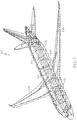
- Fig. 1 shows a perspective view of an aircraft 100 cutaway to show a current return network 102 that may include longitudinal 104 and lateral 106 electrically conductive elements extending along a substantial portion of the aircraft 100.
- the current return network 102 also includes current carrying paths 108 extending through the wings and tail of the aircraft 100.
- the longitudinal 104 and lateral 106 elements as well as the current carrying paths 108 may be low resistance electrical wires, metal, or other conductive material including but not limited to aircraft structural elements, hydraulic lines, or dedicated current return components.
- These elements 104, 106, 108 of the current return network 102 may be connected to one another to provide a number of redundant electrical pathways that may be adapted to carry fault current, provide grounding, carry lightning current, provide electromagnetic shielding, minimize resistance and voltage differentials and provide a bleed path for electrostatic charge.
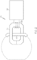
- a lightning strike detection device 112 may include a clamp-on magnetically permeable core with windings 114 that is secured about a portion of the current return network 102 and a lightning strike detection circuit 116 in communication with the ferrite core 114.
- the clamp-on ferrite core 114 is a closed loop of high-magnetic permeability material, such as iron, ferrous-oxide coated ceramics, or other material.
- the ferrite core 114 may be a removable or permanent device attached to the current return network.
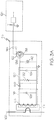
- Fig. 3A illustrates the lightning strike detection circuit 116 in further detail.
- the circuit 116 may include a resonant circuit 118, an integrator circuit 120, and a transistor 122 connected to external monitoring equipment 124.
- the resonant circuit 118 may include an inductor 126 and first capacitor 128 in parallel that is in parallel with and coupled to the integrator circuit 120 by a rectifying diode 130.
- the integrator circuit 120 includes a resistor 132 and second capacitor 134 in parallel.
- the integrator circuit 120 is tied to the gate 136 of the transistor 122 and the transistor source 138 goes to ground.
- the transistor itself 122 is shown as a normally-open enhancement-mode n-type Metal Oxide Semiconductor Field Effect Transistor (n-MOSFET) that provides a voltage controlled current source between the external monitoring equipment 124 and ground.
- Electromagnetic interference (EMI) reduction elements are provided in the form of a zener diode 142 and drain diode 144 that reduce the chance of current feedback or voltage spikes that may damage the circuit 116.
- a number of lightning strike detection devices 112 are positioned about the current return network 102 so as to capture a lightning strike event.
- the devices 112 would preferably be positioned in the Zone 3 areas and may be positioned in Zone 1 or 2 areas such as on or near the engine nacelles or along the aircraft fuselage.
- the lightning detection circuit 116 when there is no lightning strike event, the lightning detection circuit 116 will remain in an unpowered state. However, when there is a lightning strike event, the circuit will be energized to indicate the event. After the event has been indicated, the circuit will reset to an unpowered state.
- the current return network 102 forms at least one loop around the ferrite core 114 and the inductor 126 forms a number of loops about the ferrite core 114, thus forming a transformer so that when a current pulse passes through the current return network 102, the inductor 126 generates a complementary current.
- the inductor 126 and first capacitor 128 that form the resonant circuit 118 will create an alternating current output that energizes the circuit 116.
- the current output from the resonant circuit 118 is rectified by the rectifying diode 130 to a half-wave output before being transferred to the integrator circuit 120.
- the integrator circuit 120 provides a slow charge and discharge for the second capacitor 134, which preferably maintains the voltage difference across the capacitor at a threshold level for several seconds so the capacitor becomes completely charged.
- the integrator circuit provides hold time and automatic resetting for the lightning indication to remain active even if the external monitoring equipment 124 is itself upset by the event.
- the external monitoring equipment 124 is an external monitoring apparatus that may be installed in the aircraft, and may be a standard aircraft equipment interface, such as an open/ground discrete which senses the electrical open/ground discrete signal made by the circuit 116 and then uses this for fault or maintenance indication logic.
- the zener diode 142 ensures that the voltage from the transistor gate to source does not reach a level that might damage the transistor 122 or other components.
- the drain diode 144 is positioned between the external monitoring equipment 124 and transistor 122 and allows current to flow from the external monitoring equipment 124 through the transistor. This arrangement ensures that current cannot flow from the transistor 122 to the external monitoring equipment 124 and cause damage in case of a current spike in the ground.
- the circuit includes an n-MOSFET transistor 122 that is normally open and closes when a positive voltage is applied at the gate 136, allowing current to flow between the source 138 and drain 140.
- a normally closed depletion mode MOSFET may be substituted for the normally open enhancement mode transistor 122.
- the rectifying diode 130 is shown as a single diode in series between the tank circuit and integrator circuit. This half-wave rectifier only passes half of the resonant waveform generated by the resonant circuit 118 and therefore the amount of energy passed is reduced. However, this diode may be replaced with a full wave rectifier, such as a diode bridge, or other type of rectifier if additional energy is required.
- the circuit 116 has also been described as including EMI protection elements such as the zener diode 142 and drain diode 144. These elements are included to provide protection against voltage overload of the transistor 122 (zener diode 142) or current feedback to the external monitoring equipment 124. However, these elements are not necessary to operation of the circuit and may be omitted. Alternative protective elements may be included either in lieu of or in addition to these protective elements.
- the resonant circuit 118 provides an alternating current based on the lightning strike waveform, but is not necessary to provide a voltage differential to the integrator circuit 120. A current spike in the current return network 102 would produce a corresponding voltage spike in the inductor 126 that could be used to drive the transistor 122. However, the resonant circuit 118 provides the additional advantage of providing a bandlimit function to reduce the sensitivity of the circuit to radio frequency (RF) noise, for example from precipitation static or other RF noise.
- RF radio frequency
- the addition of a built in test for the detection circuit 116 may not be appropriate.
- the test function may be accomplished by the addition of a second set of windings on the ferrite core 114 that can provide a pulse to the circuit 116 to simulate a lightning strike. This would serve as an effective test to determine that the system is functioning properly.
- the current return network 102 may serve as a ground for the electrical components of the aircraft.
- the surge from a lightning strike through the current return network 102 is often what causes electrical failures in various systems of the aircraft. Therefore, it may be undesirable to use the current return network 102 as a ground for the lightning strike detection circuit 116.
- the external monitoring equipment 124 is connected to a ground, such as the current return network 102, and the lightning strike detection circuit 116 is connected to an independent ground.
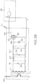
- Fig. 3B shows an alternative arrangement where the lightning strike detection circuit 116 and external monitoring equipment share a common ground 146, which may be an independent ground.
Description
- The current disclosure relates to a current spike detector and more specifically to an electrical circuit for detecting lightning strikes in aircraft.
- Lightning strikes on aircraft are relatively rare events, yet occur with sufficient frequency and are sufficiently damaging to mechanical and electrical systems that lightning strike prevention and mitigation are important components within an aircraft.
- Reporting of lightning strikes, their location, intensity, and effects are presently handled by the aircraft and ground crews. The aircraft crew is responsible for determining whether the aircraft has been struck, typically through visual confirmation or short-lived electrical interference of instrumentation or lighting. The ground crew is then tasked to determine the severity, location, and impact of the lightning strike on the flightworthiness of the aircraft. However, because this system is based on an initial determination by the aircraft crew, this system of reporting may result in over or under reporting of strikes.
- When lightning strikes an aircraft a large amount of current passes through the aircraft. In a metal skinned aircraft, this current is predominantly carried over the exterior surfaces of the aircraft. However, aircraft using composite construction often incorporate a lightning or current return network of electrical connectors, installed within the aircraft, to carry the large currents which result from lightning strikes, in such composite aircraft, this current may be directed through a current return network that reduces the chance of electrical systems being damaged by the current spike. However, some temporary electrical system failures may still occur. When these systems recover, they issue a warning, typically to the cockpit although they may be recorded elsewhere, that must be checked by a maintenance crew when the aircraft is next grounded.
- Some of these electrical system warnings may be so-called "nuisance warnings" that occur due to the system resetting because of the lightning strike rather than any problem with the system. However, these systems will still require manual resetting by a maintenance worker to reset the warnings and determine if the fault was due to the li lightning strike event or a problem in the affected system.
- Therefore, there is recognized a need in the art for a lightning detection system.
-
EP 0549432A discloses a surge arrester comprising: a varistor stack, two contact pieces made of an electrically conductive material and placed respectively on the ends of the varistor stack, and an envelope of composite material surrounding the varistor stack. The surge arrester further includes a fault signalling device to signal the passage of a leakage current through the surge arrester. -
FR 293063 - According to an aspect of the present invention there is provided a self-powered system for detecting a lightning strike including a current return network receiving and dissipating the lightning strike, a resonant circuit having a transformer in communication with the current return network and providing an alternating electrical output, a rectifier for rectifying the alternating electrical output into a direct electrical output, an integrator circuit that builds to a voltage threshold when the direct electrical output is received, including a second capacitor; an output transistor triggered to change state by the integrator circuit when the voltage threshold is reached; and external monitoring equipment connected to the output transistor by a diode such that current flows from the external monitoring equipment to the output transistor. Advantageously the current return network includes an electrically conductive path within an aircraft. The resonant circuit includes an inductor and a first capacitor. Preferably the capacitor is completely charged.
- According to a further aspect of the present invention there is provided a method of detecting a lightning strike in a current return network, the method includes the steps of providing a ferrite core in inductive communication with the current return network, providing a detection circuit having a resonant circuit in inductive communication with the ferrite core, an integrator circuit, and a transistor, inductively energizing the resonant circuit by a current spike in the current return network to provide an alternating current, rectifying the alternating current by a rectifier, charging a second capacitor in the integrator circuit by the rectified current to a threshold voltage level, changing the transistor's state when the threshold voltage level is reached, and detecting the change in state as indicative of the lightning strike, wherein the resonant circuit comprises an inductor and a first capacitor. Advantageously the rectification is by means of a half-wave rectifier. Preferably the current return network, the inductor, and the ferrite core form a transformer. Preferably the ferrite core is selectively removable from the current return network. Preferably the method further includes the step of attaching the ferrite core to the current return network. Advantageously the transistor is a normally open n-type Metal Oxide Semiconductor Field Effect Transistor (n-MOSFET). Preferably the method further includes the step of providing a remote fault monitor. Preferably the current flow from the remote fault monitor through the
transistor is used to detect the change in state. Preferably the method further includes a resistor for bleeding off the threshold voltage once the change in state is detected. As another example there is provided a method for determining whether a lightning strike has occurred on an aircraft, the method including the steps of providing a current return network throughout the aircraft, providing a passive electrical circuit in inductive communication with the current return network by means of a magnetically permeable core, the passive electrical circuit including a voltage controlled transistor, directing a current spike from a lightning strike through the current return network, transforming the current spike though the current return network into a current source in the electrical circuit, providing a threshold voltage level across the transistor to change the transistor from a normal state to an activated state, and determining the lightning strike by measuring the change. Advantageously the transistor changes from a normally open state to a closed state when the threshold voltage level is reached. Preferably the change is measured by a current draw through the transistor. Advantageously the transistor changes from a normally closed state to an open state when the threshold voltage level is reached. Preferably the change is measured by current ceasing to flow through the transistor. - The features, functions, and advantages that have been discussed can be achieved independently in various embodiments of the present invention or may be combined in yet other embodiments further details of which can be seen with reference to the following description and drawings.
-
-
Fig. 1 is a perspective view of an aircraft showing a current return network. -
Fig. 2 is a schematic view showing the attachment between the current return network and a detection circuit. -
Fig. 3A is a schematic view of the detection circuit. -
Fig. 3B is a schematic view of an alternative embodiment of the detection circuit. -
Fig. 1 shows a perspective view of anaircraft 100 cutaway to show acurrent return network 102 that may include longitudinal 104 and lateral 106 electrically conductive elements extending along a substantial portion of theaircraft 100. Thecurrent return network 102 also includescurrent carrying paths 108 extending through the wings and tail of theaircraft 100. The longitudinal 104 and lateral 106 elements as well as thecurrent carrying paths 108 may be low resistance electrical wires, metal, or other conductive material including but not limited to aircraft structural elements, hydraulic lines, or dedicated current return components. Theseelements current return network 102 may be connected to one another to provide a number of redundant electrical pathways that may be adapted to carry fault current, provide grounding, carry lightning current, provide electromagnetic shielding, minimize resistance and voltage differentials and provide a bleed path for electrostatic charge. - As shown in
Fig. 2 , a lightningstrike detection device 112 may include a clamp-on magnetically permeable core withwindings 114 that is secured about a portion of thecurrent return network 102 and a lightningstrike detection circuit 116 in communication with theferrite core 114. The clamp-onferrite core 114 is a closed loop of high-magnetic permeability material, such as iron, ferrous-oxide coated ceramics, or other material. Theferrite core 114 may be a removable or permanent device attached to the current return network. -
Fig. 3A illustrates the lightningstrike detection circuit 116 in further detail. As shown in this figure, thecircuit 116 may include aresonant circuit 118, anintegrator circuit 120, and atransistor 122 connected toexternal monitoring equipment 124. Theresonant circuit 118 may include aninductor 126 andfirst capacitor 128 in parallel that is in parallel with and coupled to theintegrator circuit 120 by a rectifyingdiode 130. Theintegrator circuit 120 includes aresistor 132 andsecond capacitor 134 in parallel. Theintegrator circuit 120 is tied to thegate 136 of thetransistor 122 and thetransistor source 138 goes to ground. The transistor itself 122 is shown as a normally-open enhancement-mode n-type Metal Oxide Semiconductor Field Effect Transistor (n-MOSFET) that provides a voltage controlled current source between theexternal monitoring equipment 124 and ground. Electromagnetic interference (EMI) reduction elements are provided in the form of azener diode 142 anddrain diode 144 that reduce the chance of current feedback or voltage spikes that may damage thecircuit 116. - According to one embodiment, a number of lightning
strike detection devices 112 are positioned about thecurrent return network 102 so as to capture a lightning strike event. With reference toFig. 2 , thedevices 112 would preferably be positioned in the Zone 3 areas and may be positioned in Zone 1 or 2 areas such as on or near the engine nacelles or along the aircraft fuselage. - With reference to
Fig. 2 , the operation of thelightning strike device 112 will be described in further detail. As will be appreciated, when there is no lightning strike event, thelightning detection circuit 116 will remain in an unpowered state. However, when there is a lightning strike event, the circuit will be energized to indicate the event. After the event has been indicated, the circuit will reset to an unpowered state. - When lightning strikes the aircraft, a current spike lasting from 1-50µs is transferred to the
current return network 102. Thecurrent return network 102 forms at least one loop around theferrite core 114 and theinductor 126 forms a number of loops about theferrite core 114, thus forming a transformer so that when a current pulse passes through thecurrent return network 102, theinductor 126 generates a complementary current. - The
inductor 126 andfirst capacitor 128 that form theresonant circuit 118 will create an alternating current output that energizes thecircuit 116. The current output from theresonant circuit 118 is rectified by the rectifyingdiode 130 to a half-wave output before being transferred to theintegrator circuit 120. - The
integrator circuit 120 provides a slow charge and discharge for thesecond capacitor 134, which preferably maintains the voltage difference across the capacitor at a threshold level for several seconds so the capacitor becomes completely charged. The integrator circuit provides hold time and automatic resetting for the lightning indication to remain active even if theexternal monitoring equipment 124 is itself upset by the event. - When the
second capacitor 134 is at a threshold level measured by the gate threshold of thetransistor 122, the circuit between thesource 138 and drain 140 is closed, allowing current to flow through the transistor from theexternal monitoring equipment 124 to ground. Theexternal monitoring equipment 124 is an external monitoring apparatus that may be installed in the aircraft, and may be a standard aircraft equipment interface, such as an open/ground discrete which senses the electrical open/ground discrete signal made by thecircuit 116 and then uses this for fault or maintenance indication logic. - The
zener diode 142 ensures that the voltage from the transistor gate to source does not reach a level that might damage thetransistor 122 or other components. - The
drain diode 144 is positioned between theexternal monitoring equipment 124 andtransistor 122 and allows current to flow from theexternal monitoring equipment 124 through the transistor. This arrangement ensures that current cannot flow from thetransistor 122 to theexternal monitoring equipment 124 and cause damage in case of a current spike in the ground. - Other improvements to the above-described electrical circuit are also contemplated. According to the embodiment illustrated, the circuit includes an n-
MOSFET transistor 122 that is normally open and closes when a positive voltage is applied at thegate 136, allowing current to flow between thesource 138 and drain 140. However, it is contemplated that a normally closed depletion mode MOSFET may be substituted for the normally openenhancement mode transistor 122. - The rectifying
diode 130 is shown as a single diode in series between the tank circuit and integrator circuit. This half-wave rectifier only passes half of the resonant waveform generated by theresonant circuit 118 and therefore the amount of energy passed is reduced. However, this diode may be replaced with a full wave rectifier, such as a diode bridge, or other type of rectifier if additional energy is required. - The
circuit 116 has also been described as including EMI protection elements such as thezener diode 142 anddrain diode 144. These elements are included to provide protection against voltage overload of the transistor 122 (zener diode 142) or current feedback to theexternal monitoring equipment 124. However, these elements are not necessary to operation of the circuit and may be omitted. Alternative protective elements may be included either in lieu of or in addition to these protective elements. - The
resonant circuit 118 provides an alternating current based on the lightning strike waveform, but is not necessary to provide a voltage differential to theintegrator circuit 120. A current spike in thecurrent return network 102 would produce a corresponding voltage spike in theinductor 126 that could be used to drive thetransistor 122. However, theresonant circuit 118 provides the additional advantage of providing a bandlimit function to reduce the sensitivity of the circuit to radio frequency (RF) noise, for example from precipitation static or other RF noise. - As a passive element with a single wire connection (current return network 112), the addition of a built in test for the
detection circuit 116 may not be appropriate. The test function may be accomplished by the addition of a second set of windings on theferrite core 114 that can provide a pulse to thecircuit 116 to simulate a lightning strike. This would serve as an effective test to determine that the system is functioning properly. - As described with reference to
Fig. 1 , thecurrent return network 102 may serve as a ground for the electrical components of the aircraft. However, the surge from a lightning strike through thecurrent return network 102 is often what causes electrical failures in various systems of the aircraft. Therefore, it may be undesirable to use thecurrent return network 102 as a ground for the lightningstrike detection circuit 116. According to one embodiment shown inFig. 3A theexternal monitoring equipment 124 is connected to a ground, such as thecurrent return network 102, and the lightningstrike detection circuit 116 is connected to an independent ground.Fig. 3B shows an alternative arrangement where the lightningstrike detection circuit 116 and external monitoring equipment share a common ground 146, which may be an independent ground.
Claims (9)
- A self-powered system for detecting a lightning strike comprising:a current return network (102) receiving and dissipating the lightning strike;a resonant circuit (118) having a transformer in communication with the current return network (102) and providing an alternating electrical output;a rectifier (130) for rectifying the alternating electrical output into a direct electrical output;an integrator circuit (120) that builds to a voltage threshold when the direct electrical output is received, including a second capacitor (134);an output transistor (122) triggered to change state by the integrator circuit (120) when the voltage threshold is reached; andexternal monitoring equipment (124) connected to the output transistor (122) by a diode (144) such that current flows from the external monitoring equipment (124) to the output transistor (122),wherein the resonant circuit (118) includes an inductor (126) and a first capacitor (128).
- The system of claim 1, wherein the current return network (102) comprises an electrically conductive path within an aircraft (100).
- A method of detecting a lightning strike in a current return network (102) of an aircraft, the method comprising the steps of:providing a ferrite core (114) in inductive communication with the current return network (102);providing a detection circuit (116) having a resonant circuit (118) in inductive communication with the ferrite core (114), an integrator circuit (120), and a transistor (122);providing external monitoring equipment (124) connected to the transistor (122) by a diode (144) such that current flows from the external monitoring equipment (124) to the transistor (122);inductively energizing the resonant circuit (118) by a current spike in the current return network (102) to provide an alternating current;rectifying the alternating current by a rectifier;charging a second capacitor (134) in the integrator circuit (120) by the rectified current to a threshold voltage level;changing the transistor's state when the threshold voltage level is reached; anddetecting the change in state as indicative of the lightning strike,wherein the resonant circuit (118) comprises an inductor (126) and a first capacitor (128).
- The method of claim 3, wherein the rectification is by means of a half-wave rectifier.
- The method of claim 3, wherein the current return network (102), the inductor (126), and the ferrite core (114) form a transformer.
- The method of any of claims 3 to 5, wherein the ferrite core (114) is selectively removable from the current return network (102).
- The method of claim 6, further comprising the step of attaching the ferrite core (114) to the current return network (102).
- The method of claim 3, wherein current flow from the external monitoring equipment (124) through the transistor (122) is used to detect the change in state.
- An aircraft comprising the assembly of any of claims 1 and 2.
Priority Applications (1)
| Application Number | Priority Date | Filing Date | Title |
|---|---|---|---|
| EP18199445.0A EP3444621B1 (en) | 2011-10-25 | 2012-09-25 | Method and apparatus for detecting a lightning strike |
Applications Claiming Priority (2)
| Application Number | Priority Date | Filing Date | Title |
|---|---|---|---|
| US13/280,915 US8841898B2 (en) | 2011-10-25 | 2011-10-25 | Method and apparatus for detecting a lightning strike |
| PCT/US2012/057151 WO2013062706A1 (en) | 2011-10-25 | 2012-09-25 | Method and apparatus for detecting a lightning strike |
Related Child Applications (2)
| Application Number | Title | Priority Date | Filing Date |
|---|---|---|---|
| EP18199445.0A Division EP3444621B1 (en) | 2011-10-25 | 2012-09-25 | Method and apparatus for detecting a lightning strike |
| EP18199445.0A Division-Into EP3444621B1 (en) | 2011-10-25 | 2012-09-25 | Method and apparatus for detecting a lightning strike |
Publications (2)
| Publication Number | Publication Date |
|---|---|
| EP2771702A1 EP2771702A1 (en) | 2014-09-03 |
| EP2771702B1 true EP2771702B1 (en) | 2018-11-21 |
Family
ID=47215717
Family Applications (2)
| Application Number | Title | Priority Date | Filing Date |
|---|---|---|---|
| EP18199445.0A Active EP3444621B1 (en) | 2011-10-25 | 2012-09-25 | Method and apparatus for detecting a lightning strike |
| EP12788323.9A Active EP2771702B1 (en) | 2011-10-25 | 2012-09-25 | Method and apparatus for detecting a lightning strike |
Family Applications Before (1)
| Application Number | Title | Priority Date | Filing Date |
|---|---|---|---|
| EP18199445.0A Active EP3444621B1 (en) | 2011-10-25 | 2012-09-25 | Method and apparatus for detecting a lightning strike |
Country Status (7)
| Country | Link |
|---|---|
| US (1) | US8841898B2 (en) |
| EP (2) | EP3444621B1 (en) |
| JP (1) | JP6076366B2 (en) |
| BR (1) | BR112014008987B1 (en) |
| CA (1) | CA2844412C (en) |
| RU (1) | RU2611109C2 (en) |
| WO (1) | WO2013062706A1 (en) |
Families Citing this family (13)
| Publication number | Priority date | Publication date | Assignee | Title |
|---|---|---|---|---|
| US20170307672A9 (en) * | 2013-01-29 | 2017-10-26 | Smart Drilling And Completion, Inc. | Stable grounding system to avoid catastrophic electrical failures in fiber-reinforced composite aircraft |
| US9488609B2 (en) * | 2014-02-06 | 2016-11-08 | The Boeing Company | Determination of anisotropic conduction characteristics |
| US9748759B1 (en) | 2014-05-09 | 2017-08-29 | Donald J. Bergeron | Lightning electromagnetic pulse (LEMP) detector and isolation device |
| DE102016000930A1 (en) * | 2015-09-04 | 2017-03-09 | DEHN + SÖHNE GmbH + Co. KG. | Method for detecting lightning current parameters on installations with one or more catching devices and lightning current discharge paths |
| JP6562354B2 (en) * | 2015-11-25 | 2019-08-21 | パナソニックIpマネジメント株式会社 | Power supply device and lighting fixture |
| CN105527515A (en) * | 2015-12-02 | 2016-04-27 | 无锡拓能自动化科技有限公司 | Mutual inductance self-powered monitoring device for high voltage switch cabinet |
| CN108205076A (en) * | 2018-03-06 | 2018-06-26 | 苏宇宁 | Lightning protection potential difference test method |
| DE102018114356B4 (en) * | 2018-06-15 | 2024-04-04 | Airbus Operations Gmbh | Aircraft with a fuselage, a wing and a tail unit as well as a surface structure containing a lightning protection device |
| RU2714526C1 (en) * | 2019-06-19 | 2020-02-18 | Общество с ограниченной ответственностью "Челэнергоприбор" | Current pulse counter through overvoltage limiter |
| US11420765B2 (en) * | 2020-03-26 | 2022-08-23 | Aerion Intellectual Property Management Corporation | Aircraft fuselage with internal current return network |
| TWI758831B (en) * | 2020-08-21 | 2022-03-21 | 安雷科技股份有限公司 | Lightning strike counter and lightning strike counting method |
| JP7204999B1 (en) * | 2021-02-19 | 2023-01-16 | 三菱電機株式会社 | Lightning Strike Determination Control Device, Power Supply System, and Lightning Strike Determination Control Method |
| US11879931B2 (en) * | 2021-08-25 | 2024-01-23 | Hamilton Sundstrand Corporation | Circuit testing and diagnosis |
Family Cites Families (32)
| Publication number | Priority date | Publication date | Assignee | Title |
|---|---|---|---|---|
| US2114865A (en) * | 1937-02-06 | 1938-04-19 | Gen Electric | Peak alternating current measuring apparatus |
| US3889185A (en) | 1974-04-15 | 1975-06-10 | Nasa | Lightning current measuring systems |
| JPS6146613A (en) * | 1984-08-10 | 1986-03-06 | Nec Corp | Level detecting circuit |
| FR2624319B1 (en) | 1987-12-07 | 1990-05-04 | Lewiner Jacques | ION EMISSION LIGHTNING PROTECTION DEVICES |
| FR2685532B1 (en) | 1991-12-20 | 1994-12-30 | Soule Sa | SURGE PROTECTOR WITH IMPROVED MECHANICAL PROPERTIES. |
| JPH06281688A (en) * | 1993-03-26 | 1994-10-07 | Ngk Insulators Ltd | Displaying device for accident of transmission and distribution cable way |
| FR2713345B1 (en) | 1993-12-03 | 1996-01-05 | Alcatel Cable | Impulse energy measurement device. |
| FR2718898B1 (en) | 1994-04-18 | 1996-06-28 | Jacques Lewiner | Method and device for monitoring lightning protection equipment. |
| US5446431A (en) * | 1994-04-28 | 1995-08-29 | Square D Company | Ground fault module conductors and base therefor |
| NL1001035C2 (en) | 1995-08-23 | 1997-02-25 | Heide Beheer B V V D | Device for recording lightning strikes. |
| US6114814A (en) * | 1998-12-11 | 2000-09-05 | Monolithic Power Systems, Inc. | Apparatus for controlling a discharge lamp in a backlighted display |
| JP3266884B2 (en) * | 1999-10-15 | 2002-03-18 | 義宏 平川 | Lightning detector |
| JP4748404B2 (en) * | 2000-07-31 | 2011-08-17 | 中部電力株式会社 | Current detection device and ground fault display device |
| US6924566B2 (en) * | 2001-08-08 | 2005-08-02 | Adtran, Inc. | Method for assuring start-up of span-powered telecommunication systems |
| JP2003059614A (en) | 2001-08-10 | 2003-02-28 | Mitsubishi Electric Corp | Lighting arrester operation detecting device |
| US7245511B2 (en) * | 2004-08-25 | 2007-07-17 | Itron, Inc. | Resistor dropper power supply with surge protection |
| US7890891B2 (en) * | 2005-07-11 | 2011-02-15 | Peregrine Semiconductor Corporation | Method and apparatus improving gate oxide reliability by controlling accumulated charge |
| US7193428B1 (en) * | 2006-01-19 | 2007-03-20 | Veris Industries, Llc | Low threshold current switch |
| US7525785B2 (en) * | 2006-12-14 | 2009-04-28 | The Boeing Company | Lightning strike protection method and apparatus |
| FR2911440B1 (en) * | 2007-01-12 | 2009-04-10 | Abb France | DEVICE AND METHOD FOR MEASURING LIGHTNING CURRENT |
| RU2339547C9 (en) * | 2007-03-27 | 2009-01-20 | Федеральное государственное унитарное предприятие "Летно-исследовательский институт имени М.М. Громова" | Automated high-intelligent system for aircraft flight safety providing |
| US7417843B1 (en) * | 2007-03-28 | 2008-08-26 | Benjamin P. Fowler | System and method of protecting metallic structures from lightning strikes |
| CA2609611A1 (en) * | 2007-09-10 | 2009-03-10 | Veris Industries, Llc | Split core status indicator |
| US7714743B1 (en) | 2007-09-14 | 2010-05-11 | Rockwell Collins, Inc. | Aircraft lightning strike detector |
| GB2458152B (en) * | 2008-03-07 | 2010-09-29 | Insensys Ltd | Lightning detection |
| US8179653B2 (en) * | 2008-07-17 | 2012-05-15 | Advanced Protection Technologies, Inc. | Multiple operating voltage electrical surge protection apparatus |
| RU2395434C2 (en) * | 2008-08-06 | 2010-07-27 | Федеральное государственное унитарное предприятие "Лётно-исследовательский институт имени М.М. Громова" | Aircraft lightning protection device |
| FR2936063B1 (en) | 2008-09-17 | 2010-12-10 | Indelec | DEVICE FOR DETECTING PHYSICAL EVENTS IN AN ELECTRICAL CONDUCTOR. |
| US8031458B2 (en) | 2008-11-24 | 2011-10-04 | The Boeing Company | Current return network |
| US8005617B2 (en) * | 2010-11-29 | 2011-08-23 | General Electric Company | System and method for detecting lightning strikes likely to affect a condition of a structure |
| US20120154021A1 (en) * | 2010-12-20 | 2012-06-21 | Amita Chandrakant Patil | Integrated circuit and method of fabricating same |
| TWI440394B (en) * | 2011-04-20 | 2014-06-01 | Univ Nat Chi Nan | Optical power compensation circuit and device, detection module |
-
2011
- 2011-10-25 US US13/280,915 patent/US8841898B2/en active Active
-
2012
- 2012-09-25 BR BR112014008987-6A patent/BR112014008987B1/en active IP Right Grant
- 2012-09-25 EP EP18199445.0A patent/EP3444621B1/en active Active
- 2012-09-25 CA CA2844412A patent/CA2844412C/en active Active
- 2012-09-25 EP EP12788323.9A patent/EP2771702B1/en active Active
- 2012-09-25 RU RU2014116073A patent/RU2611109C2/en active
- 2012-09-25 JP JP2014538800A patent/JP6076366B2/en active Active
- 2012-09-25 WO PCT/US2012/057151 patent/WO2013062706A1/en active Application Filing
Non-Patent Citations (1)
| Title |
|---|
| None * |
Also Published As
| Publication number | Publication date |
|---|---|
| CA2844412C (en) | 2017-10-24 |
| CA2844412A1 (en) | 2013-05-02 |
| EP3444621B1 (en) | 2020-03-18 |
| BR112014008987A2 (en) | 2017-05-02 |
| RU2611109C2 (en) | 2017-02-21 |
| BR112014008987B1 (en) | 2021-01-19 |
| EP2771702A1 (en) | 2014-09-03 |
| EP3444621A1 (en) | 2019-02-20 |
| WO2013062706A1 (en) | 2013-05-02 |
| JP2014534437A (en) | 2014-12-18 |
| US20130099772A1 (en) | 2013-04-25 |
| JP6076366B2 (en) | 2017-02-08 |
| US8841898B2 (en) | 2014-09-23 |
| RU2014116073A (en) | 2015-12-10 |
Similar Documents
| Publication | Publication Date | Title |
|---|---|---|
| EP2771702B1 (en) | Method and apparatus for detecting a lightning strike | |
| US10938204B1 (en) | System and method for detecting and isolating an electromagnetic pulse for protection of a monitored infrastructure | |
| CN110445109A (en) | A kind of quick removing method and device of Ferroresonance Overvoltage Caused by PT | |
| US20160025794A1 (en) | Apparatus and method for detecting leakage current | |
| KR101521134B1 (en) | System for warning thunderbolt and prevention | |
| CN111323680A (en) | Method and circuit for detecting arc faults | |
| US20150179363A1 (en) | Device for the safe switching of a photovoltaic system | |
| WO2018141259A1 (en) | Grounding monitoring system, method and device, and computer-readable storage medium | |
| AU2012355651B2 (en) | High speed signaling of power system conditions | |
| US5136456A (en) | Faulted current indicator with protection against temporary overloads and transients | |
| CN207007960U (en) | A kind of overhead transmission line Zinc oxide arrester monitoring device | |
| CN104977452A (en) | Failure protection mutual inductor tail current detection method | |
| US7714743B1 (en) | Aircraft lightning strike detector | |
| CN210327013U (en) | Back-up protector control system of surge protector | |
| CN106849044B (en) | A kind of invariable power overvoltage intelligence short-circuit protector | |
| CN112398105A (en) | Backup protector control system of surge protector and operation method thereof | |
| KR200465727Y1 (en) | Electric insulation monitoring system of ground feeding cable | |
| JP5744602B2 (en) | Current transformer protection device | |
| CN110829399A (en) | Lightning protection comprehensive management method and device | |
| EP3953956B1 (en) | Disconnector device with passive radio device, grid protection system having the disconnector device, and method for indicating a state of the disconnector device | |
| Okai et al. | Cable fault detection system employing remote terminals without DC power supply using digital communication over optical fibres | |
| Mikeš et al. | Highly Efficient Portable Lightning Strike Counter-Case Study of Its Implementation and Testing | |
| CN110364998A (en) | Electric system lightning stroke earth protective device | |
| CN102646956A (en) | Electric leakage protection device | |
| JPH0341002B2 (en) |
Legal Events
| Date | Code | Title | Description |
|---|---|---|---|
| PUAI | Public reference made under article 153(3) epc to a published international application that has entered the european phase |
Free format text: ORIGINAL CODE: 0009012 |
|
| 17P | Request for examination filed |
Effective date: 20140304 |
|
| AK | Designated contracting states |
Kind code of ref document: A1 Designated state(s): AL AT BE BG CH CY CZ DE DK EE ES FI FR GB GR HR HU IE IS IT LI LT LU LV MC MK MT NL NO PL PT RO RS SE SI SK SM TR |
|
| DAX | Request for extension of the european patent (deleted) | ||
| STAA | Information on the status of an ep patent application or granted ep patent |
Free format text: STATUS: EXAMINATION IS IN PROGRESS |
|
| 17Q | First examination report despatched |
Effective date: 20171222 |
|
| GRAP | Despatch of communication of intention to grant a patent |
Free format text: ORIGINAL CODE: EPIDOSNIGR1 |
|
| STAA | Information on the status of an ep patent application or granted ep patent |
Free format text: STATUS: GRANT OF PATENT IS INTENDED |
|
| INTG | Intention to grant announced |
Effective date: 20180607 |
|
| GRAS | Grant fee paid |
Free format text: ORIGINAL CODE: EPIDOSNIGR3 |
|
| GRAA | (expected) grant |
Free format text: ORIGINAL CODE: 0009210 |
|
| STAA | Information on the status of an ep patent application or granted ep patent |
Free format text: STATUS: THE PATENT HAS BEEN GRANTED |
|
| AK | Designated contracting states |
Kind code of ref document: B1 Designated state(s): AL AT BE BG CH CY CZ DE DK EE ES FI FR GB GR HR HU IE IS IT LI LT LU LV MC MK MT NL NO PL PT RO RS SE SI SK SM TR |
|
| REG | Reference to a national code |
Ref country code: CH Ref legal event code: EP |
|
| REG | Reference to a national code |
Ref country code: IE Ref legal event code: FG4D |
|
| REG | Reference to a national code |
Ref country code: DE Ref legal event code: R096 Ref document number: 602012053840 Country of ref document: DE |
|
| REG | Reference to a national code |
Ref country code: AT Ref legal event code: REF Ref document number: 1068164 Country of ref document: AT Kind code of ref document: T Effective date: 20181215 |
|
| REG | Reference to a national code |
Ref country code: NL Ref legal event code: MP Effective date: 20181121 |
|
| REG | Reference to a national code |
Ref country code: AT Ref legal event code: MK05 Ref document number: 1068164 Country of ref document: AT Kind code of ref document: T Effective date: 20181121 |
|
| PG25 | Lapsed in a contracting state [announced via postgrant information from national office to epo] |
Ref country code: ES Free format text: LAPSE BECAUSE OF FAILURE TO SUBMIT A TRANSLATION OF THE DESCRIPTION OR TO PAY THE FEE WITHIN THE PRESCRIBED TIME-LIMIT Effective date: 20181121 Ref country code: AT Free format text: LAPSE BECAUSE OF FAILURE TO SUBMIT A TRANSLATION OF THE DESCRIPTION OR TO PAY THE FEE WITHIN THE PRESCRIBED TIME-LIMIT Effective date: 20181121 Ref country code: NO Free format text: LAPSE BECAUSE OF FAILURE TO SUBMIT A TRANSLATION OF THE DESCRIPTION OR TO PAY THE FEE WITHIN THE PRESCRIBED TIME-LIMIT Effective date: 20190221 Ref country code: IS Free format text: LAPSE BECAUSE OF FAILURE TO SUBMIT A TRANSLATION OF THE DESCRIPTION OR TO PAY THE FEE WITHIN THE PRESCRIBED TIME-LIMIT Effective date: 20190321 Ref country code: FI Free format text: LAPSE BECAUSE OF FAILURE TO SUBMIT A TRANSLATION OF THE DESCRIPTION OR TO PAY THE FEE WITHIN THE PRESCRIBED TIME-LIMIT Effective date: 20181121 Ref country code: LT Free format text: LAPSE BECAUSE OF FAILURE TO SUBMIT A TRANSLATION OF THE DESCRIPTION OR TO PAY THE FEE WITHIN THE PRESCRIBED TIME-LIMIT Effective date: 20181121 Ref country code: HR Free format text: LAPSE BECAUSE OF FAILURE TO SUBMIT A TRANSLATION OF THE DESCRIPTION OR TO PAY THE FEE WITHIN THE PRESCRIBED TIME-LIMIT Effective date: 20181121 Ref country code: BG Free format text: LAPSE BECAUSE OF FAILURE TO SUBMIT A TRANSLATION OF THE DESCRIPTION OR TO PAY THE FEE WITHIN THE PRESCRIBED TIME-LIMIT Effective date: 20190221 Ref country code: LV Free format text: LAPSE BECAUSE OF FAILURE TO SUBMIT A TRANSLATION OF THE DESCRIPTION OR TO PAY THE FEE WITHIN THE PRESCRIBED TIME-LIMIT Effective date: 20181121 |
|
| PG25 | Lapsed in a contracting state [announced via postgrant information from national office to epo] |
Ref country code: NL Free format text: LAPSE BECAUSE OF FAILURE TO SUBMIT A TRANSLATION OF THE DESCRIPTION OR TO PAY THE FEE WITHIN THE PRESCRIBED TIME-LIMIT Effective date: 20181121 Ref country code: RS Free format text: LAPSE BECAUSE OF FAILURE TO SUBMIT A TRANSLATION OF THE DESCRIPTION OR TO PAY THE FEE WITHIN THE PRESCRIBED TIME-LIMIT Effective date: 20181121 Ref country code: AL Free format text: LAPSE BECAUSE OF FAILURE TO SUBMIT A TRANSLATION OF THE DESCRIPTION OR TO PAY THE FEE WITHIN THE PRESCRIBED TIME-LIMIT Effective date: 20181121 Ref country code: SE Free format text: LAPSE BECAUSE OF FAILURE TO SUBMIT A TRANSLATION OF THE DESCRIPTION OR TO PAY THE FEE WITHIN THE PRESCRIBED TIME-LIMIT Effective date: 20181121 Ref country code: GR Free format text: LAPSE BECAUSE OF FAILURE TO SUBMIT A TRANSLATION OF THE DESCRIPTION OR TO PAY THE FEE WITHIN THE PRESCRIBED TIME-LIMIT Effective date: 20190222 Ref country code: PT Free format text: LAPSE BECAUSE OF FAILURE TO SUBMIT A TRANSLATION OF THE DESCRIPTION OR TO PAY THE FEE WITHIN THE PRESCRIBED TIME-LIMIT Effective date: 20190321 |
|
| PG25 | Lapsed in a contracting state [announced via postgrant information from national office to epo] |
Ref country code: DK Free format text: LAPSE BECAUSE OF FAILURE TO SUBMIT A TRANSLATION OF THE DESCRIPTION OR TO PAY THE FEE WITHIN THE PRESCRIBED TIME-LIMIT Effective date: 20181121 Ref country code: PL Free format text: LAPSE BECAUSE OF FAILURE TO SUBMIT A TRANSLATION OF THE DESCRIPTION OR TO PAY THE FEE WITHIN THE PRESCRIBED TIME-LIMIT Effective date: 20181121 Ref country code: IT Free format text: LAPSE BECAUSE OF FAILURE TO SUBMIT A TRANSLATION OF THE DESCRIPTION OR TO PAY THE FEE WITHIN THE PRESCRIBED TIME-LIMIT Effective date: 20181121 Ref country code: CZ Free format text: LAPSE BECAUSE OF FAILURE TO SUBMIT A TRANSLATION OF THE DESCRIPTION OR TO PAY THE FEE WITHIN THE PRESCRIBED TIME-LIMIT Effective date: 20181121 |
|
| REG | Reference to a national code |
Ref country code: DE Ref legal event code: R097 Ref document number: 602012053840 Country of ref document: DE |
|
| PG25 | Lapsed in a contracting state [announced via postgrant information from national office to epo] |
Ref country code: SK Free format text: LAPSE BECAUSE OF FAILURE TO SUBMIT A TRANSLATION OF THE DESCRIPTION OR TO PAY THE FEE WITHIN THE PRESCRIBED TIME-LIMIT Effective date: 20181121 Ref country code: EE Free format text: LAPSE BECAUSE OF FAILURE TO SUBMIT A TRANSLATION OF THE DESCRIPTION OR TO PAY THE FEE WITHIN THE PRESCRIBED TIME-LIMIT Effective date: 20181121 Ref country code: SM Free format text: LAPSE BECAUSE OF FAILURE TO SUBMIT A TRANSLATION OF THE DESCRIPTION OR TO PAY THE FEE WITHIN THE PRESCRIBED TIME-LIMIT Effective date: 20181121 Ref country code: RO Free format text: LAPSE BECAUSE OF FAILURE TO SUBMIT A TRANSLATION OF THE DESCRIPTION OR TO PAY THE FEE WITHIN THE PRESCRIBED TIME-LIMIT Effective date: 20181121 |
|
| PLBE | No opposition filed within time limit |
Free format text: ORIGINAL CODE: 0009261 |
|
| STAA | Information on the status of an ep patent application or granted ep patent |
Free format text: STATUS: NO OPPOSITION FILED WITHIN TIME LIMIT |
|
| 26N | No opposition filed |
Effective date: 20190822 |
|
| PG25 | Lapsed in a contracting state [announced via postgrant information from national office to epo] |
Ref country code: SI Free format text: LAPSE BECAUSE OF FAILURE TO SUBMIT A TRANSLATION OF THE DESCRIPTION OR TO PAY THE FEE WITHIN THE PRESCRIBED TIME-LIMIT Effective date: 20181121 |
|
| PG25 | Lapsed in a contracting state [announced via postgrant information from national office to epo] |
Ref country code: TR Free format text: LAPSE BECAUSE OF FAILURE TO SUBMIT A TRANSLATION OF THE DESCRIPTION OR TO PAY THE FEE WITHIN THE PRESCRIBED TIME-LIMIT Effective date: 20181121 |
|
| PG25 | Lapsed in a contracting state [announced via postgrant information from national office to epo] |
Ref country code: MC Free format text: LAPSE BECAUSE OF FAILURE TO SUBMIT A TRANSLATION OF THE DESCRIPTION OR TO PAY THE FEE WITHIN THE PRESCRIBED TIME-LIMIT Effective date: 20181121 |
|
| REG | Reference to a national code |
Ref country code: CH Ref legal event code: PL |
|
| PG25 | Lapsed in a contracting state [announced via postgrant information from national office to epo] |
Ref country code: IE Free format text: LAPSE BECAUSE OF NON-PAYMENT OF DUE FEES Effective date: 20190925 Ref country code: LU Free format text: LAPSE BECAUSE OF NON-PAYMENT OF DUE FEES Effective date: 20190925 Ref country code: CH Free format text: LAPSE BECAUSE OF NON-PAYMENT OF DUE FEES Effective date: 20190930 Ref country code: LI Free format text: LAPSE BECAUSE OF NON-PAYMENT OF DUE FEES Effective date: 20190930 |
|
| REG | Reference to a national code |
Ref country code: BE Ref legal event code: MM Effective date: 20190930 |
|
| PG25 | Lapsed in a contracting state [announced via postgrant information from national office to epo] |
Ref country code: BE Free format text: LAPSE BECAUSE OF NON-PAYMENT OF DUE FEES Effective date: 20190930 |
|
| PG25 | Lapsed in a contracting state [announced via postgrant information from national office to epo] |
Ref country code: CY Free format text: LAPSE BECAUSE OF FAILURE TO SUBMIT A TRANSLATION OF THE DESCRIPTION OR TO PAY THE FEE WITHIN THE PRESCRIBED TIME-LIMIT Effective date: 20181121 |
|
| PG25 | Lapsed in a contracting state [announced via postgrant information from national office to epo] |
Ref country code: MT Free format text: LAPSE BECAUSE OF FAILURE TO SUBMIT A TRANSLATION OF THE DESCRIPTION OR TO PAY THE FEE WITHIN THE PRESCRIBED TIME-LIMIT Effective date: 20181121 Ref country code: HU Free format text: LAPSE BECAUSE OF FAILURE TO SUBMIT A TRANSLATION OF THE DESCRIPTION OR TO PAY THE FEE WITHIN THE PRESCRIBED TIME-LIMIT; INVALID AB INITIO Effective date: 20120925 |
|
| PG25 | Lapsed in a contracting state [announced via postgrant information from national office to epo] |
Ref country code: MK Free format text: LAPSE BECAUSE OF FAILURE TO SUBMIT A TRANSLATION OF THE DESCRIPTION OR TO PAY THE FEE WITHIN THE PRESCRIBED TIME-LIMIT Effective date: 20181121 |
|
| P01 | Opt-out of the competence of the unified patent court (upc) registered |
Effective date: 20230516 |
|
| PGFP | Annual fee paid to national office [announced via postgrant information from national office to epo] |
Ref country code: GB Payment date: 20230927 Year of fee payment: 12 |
|
| PGFP | Annual fee paid to national office [announced via postgrant information from national office to epo] |
Ref country code: FR Payment date: 20230925 Year of fee payment: 12 Ref country code: DE Payment date: 20230927 Year of fee payment: 12 |