JP6073214B2 - Method, apparatus and processor readable medium for processing parallax - Google Patents
Method, apparatus and processor readable medium for processing parallax Download PDFInfo
- Publication number
- JP6073214B2 JP6073214B2 JP2013501979A JP2013501979A JP6073214B2 JP 6073214 B2 JP6073214 B2 JP 6073214B2 JP 2013501979 A JP2013501979 A JP 2013501979A JP 2013501979 A JP2013501979 A JP 2013501979A JP 6073214 B2 JP6073214 B2 JP 6073214B2
- Authority
- JP
- Japan
- Prior art keywords
- parallax
- resolution
- image
- value
- disparity
- Prior art date
- Legal status (The legal status is an assumption and is not a legal conclusion. Google has not performed a legal analysis and makes no representation as to the accuracy of the status listed.)
- Active
Links
- 238000000034 method Methods 0.000 title claims description 67
- 238000012545 processing Methods 0.000 title description 55
- 238000012937 correction Methods 0.000 claims description 5
- 238000012986 modification Methods 0.000 claims description 4
- 230000004048 modification Effects 0.000 claims description 4
- 230000008569 process Effects 0.000 description 53
- 230000005540 biological transmission Effects 0.000 description 37
- 238000006243 chemical reaction Methods 0.000 description 22
- 238000001914 filtration Methods 0.000 description 14
- 238000005070 sampling Methods 0.000 description 13
- 230000000903 blocking effect Effects 0.000 description 12
- 230000006870 function Effects 0.000 description 12
- 230000000694 effects Effects 0.000 description 11
- 230000008901 benefit Effects 0.000 description 10
- 238000010586 diagram Methods 0.000 description 7
- 210000001747 pupil Anatomy 0.000 description 5
- 238000004891 communication Methods 0.000 description 3
- 238000004364 calculation method Methods 0.000 description 2
- 238000003780 insertion Methods 0.000 description 2
- 230000037431 insertion Effects 0.000 description 2
- 230000003287 optical effect Effects 0.000 description 2
- 230000008520 organization Effects 0.000 description 2
- 229920001690 polydopamine Polymers 0.000 description 2
- 230000002123 temporal effect Effects 0.000 description 2
- 230000000007 visual effect Effects 0.000 description 2
- 238000009825 accumulation Methods 0.000 description 1
- 210000004556 brain Anatomy 0.000 description 1
- 239000000969 carrier Substances 0.000 description 1
- 230000000295 complement effect Effects 0.000 description 1
- 230000007812 deficiency Effects 0.000 description 1
- 238000006073 displacement reaction Methods 0.000 description 1
- 238000013213 extrapolation Methods 0.000 description 1
- 230000014509 gene expression Effects 0.000 description 1
- 238000004519 manufacturing process Methods 0.000 description 1
- 238000005192 partition Methods 0.000 description 1
- 230000008447 perception Effects 0.000 description 1
- 238000009877 rendering Methods 0.000 description 1
- 230000035807 sensation Effects 0.000 description 1
- 239000007787 solid Substances 0.000 description 1
- 238000001228 spectrum Methods 0.000 description 1
- 230000026676 system process Effects 0.000 description 1
Images


Classifications
-
- H—ELECTRICITY
- H04—ELECTRIC COMMUNICATION TECHNIQUE
- H04N—PICTORIAL COMMUNICATION, e.g. TELEVISION
- H04N13/00—Stereoscopic video systems; Multi-view video systems; Details thereof
- H04N13/10—Processing, recording or transmission of stereoscopic or multi-view image signals
- H04N13/106—Processing image signals
- H04N13/128—Adjusting depth or disparity
Landscapes
- Engineering & Computer Science (AREA)
- Multimedia (AREA)
- Signal Processing (AREA)
- Testing, Inspecting, Measuring Of Stereoscopic Televisions And Televisions (AREA)
- Image Generation (AREA)
- Television Systems (AREA)
- Processing Or Creating Images (AREA)
Description
(関連出願のクロスリファレンス)
本出願は、以下に記す各米国仮出願の出願日の法的権利を主張し、これらの米国仮出願を事実上そのままここに参照用として組み込む。
(i)出願番号61/397418、提出日2010年6月11日、発明の名称「3D Disparity Maps(3D視差マップ)」
(ii)出願番号61/319566、提出日2010年3月31日、発明の名称「Dense Disparity Maps(高密度視差マップ)」
(Cross-reference of related applications)
This application claims the legal rights of the filing dates of each of the US provisional applications described below, and these US provisional applications are incorporated herein by reference in their entirety.
(I) Application number 61/396418, filing date June 11, 2010, title of invention “3D Disparity Maps”
(Ii) Application No. 61/319566, filing date March 31, 2010, title of invention “Dense Disparity Maps”
3Dに関連した各実施形態を説明する。ここに説明する種々の特定の実施形態は、ビデオ映像用の視差マップに関する。 Each embodiment related to 3D will be described. Various specific embodiments described herein relate to a parallax map for video footage.
立体映像のビデオは、左ビデオ映像と右ビデオ映像とを含む2つのビデオ映像を提供する。奥行き及び/又は視差の情報も、この2つのビデオ映像について、提供される。この奥行き及び/又は視差の情報は、この2つのビデオ映像に関する様々な処理作業について、使用されることがある。 The stereoscopic video provides two video images including a left video image and a right video image. Depth and / or parallax information is also provided for the two video images. This depth and / or parallax information may be used for various processing tasks related to the two video images.
概括的な様相に従えば、画像内の特定の箇所についての視差値にアクセスする。視差値は、特定の解像度についての視差を示す。アクセスした視差値を複数の解像度に基づいて修正して、修正視差値を生成する。 In accordance with the general aspect, the parallax value for a particular location in the image is accessed. The parallax value indicates the parallax for a specific resolution. The accessed parallax value is corrected based on a plurality of resolutions to generate a corrected parallax value.
別の概括的な様相に従えば、信号、或いは、構造体には、画像内の特定の箇所についての視差値を含む視差部分が含まれている。画像は、特定の解像度を有している。視差値は、その特定の解像度と異なり、且つ、複数の解像度に基づく別の解像度についての視差を示す。 According to another general aspect, the signal or structure includes a parallax portion that includes a parallax value for a particular location in the image. The image has a specific resolution. The parallax value is different from the specific resolution and indicates the parallax for another resolution based on a plurality of resolutions.
別の概括的な様相に従えば、画像内の特定の箇所についての視差値にアクセスする。画像は、特定の解像度を有している。視差値は、その特定の解像度と異なり、且つ、複数の解像度に基づく別の解像度についての視差を示す。アクセスした視差値を修正して、その特定の解像度についての視差を示す修正視差値を生成する。 According to another general aspect, the parallax value for a particular location in the image is accessed. The image has a specific resolution. The parallax value is different from the specific resolution and indicates the parallax for another resolution based on a plurality of resolutions. The accessed parallax value is corrected to generate a corrected parallax value indicating the parallax for the specific resolution.
1つ以上の実施形態の詳細を、添付図面と以下の説明に於いて、述べることにする。各実施形態が、たとえ、ある特定の態様で説明されたとしても、それらの実施形態が、様々な態様で構成、或いは、具現化できることは明らかである。例えば、ある実施形態は、方法として行うことができ、或いは、装置として、例えば、一組の処理を行うように構成された装置、或いは、一組の処理を行うための各命令を格納した装置として具現化でき、或いは、信号として具現化できる。その他の各様相と各特徴は、添付図面と特許請求の範囲の各請求項と共に検討されるべき以下の詳細な説明から明らかになるであろう。 The details of one or more embodiments will be set forth in the accompanying drawings and the description below. Even though each embodiment has been described in certain specific aspects, it is obvious that those embodiments can be configured or embodied in various aspects. For example, an embodiment may be performed as a method, or as an apparatus, for example, an apparatus configured to perform a set of processes, or an apparatus storing instructions for performing a set of processes. Or as a signal. Other aspects and features will become apparent from the following detailed description, which should be considered in conjunction with the accompanying drawings and the appended claims.
本願に於いて提示する各特徴の一部を事前に説明すると、少なくとも1つの実施形態では、任意の標準的なディスプレイの最大解像度よりも相当に大きな解像度に基づいた各視差値が使用される。本願に於いて、「解像度」という用語は、一般に水平方向解像度を意味し、例えば、ディスプレイの画素数、ディスプレイの画素のブロック数、或いは、デジタル画像の要素数で測定される。この非標準的な解像度は、1つ以上の標準的なディスプレイの解像度に容易に変換できる整数である。この特定の実施形態に於いて、有効なディスプレイの解像度は、幾つかの標準的なディスプレイの解像度の最小公倍数である。この有効なディスプレイの解像度についての各視差値は、整数のフォーマットで表される。これらの各視差値は、大きな非標準的な解像度に基づく結果として、潜在的に大きくなる。また、整数で表すことによって、各視差値を標準的なディスプレイの解像度に縮小変換(ダウン・コンバート)した場合に、画素より細かい正確度が得られるようにしている。 To explain in advance some of the features presented in this application, at least one embodiment uses each disparity value based on a resolution that is significantly greater than the maximum resolution of any standard display. In this application, the term “resolution” generally means horizontal resolution, and is measured, for example, by the number of pixels of a display, the number of blocks of pixels of a display, or the number of elements of a digital image. This non-standard resolution is an integer that can be easily converted to the resolution of one or more standard displays. In this particular embodiment, the effective display resolution is the least common multiple of the resolution of some standard displays. Each disparity value for this effective display resolution is represented in an integer format. Each of these parallax values is potentially large as a result of a large non-standard resolution. In addition, by expressing each parallax value as a standard display resolution (down-conversion), an accuracy smaller than that of a pixel can be obtained by expressing the parallax value with an integer.
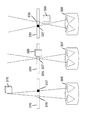
上述の事前説明から戻ると、図1には、ビデオ映像に於ける奥行きの概念が例示されている。図1には、センサ107を有する右カメラ105と、センサ112を有する左カメラ110とが示されている。両方のカメラ105及び110が、被写体115の映像を捕捉している。例示の目的で、被写体115は、物理的に十字形であり、その十字形の右側に位置する任意の細部116を有している(図2参照)。右カメラ105は捕捉角120を有し、左カメラ110は捕捉角125を有している。これらの2つの捕捉角120及び125は、3D立体領域130で、互いに重複している。
Returning to the previous description, FIG. 1 illustrates the concept of depth in a video image. FIG. 1 shows a
被写体115は、3D立体領域130に在るので、両方のカメラ105及び110に可視であり、従って、奥行きを有しているように知覚され得る。被写体115は、実際の奥行き135を有する。実際の奥行き135は、一般に、被写体115からカメラ105及び110までの距離と呼ばれている。更に具体的には、実際の奥行き135は、被写体115から立体カメラ基線140までの距離と呼んでもよく、この立体カメラ基線140は、両方のカメラ105及び110の入射ひとみ(絞り)面によって確定される面である。カメラの入射ひとみ面は、一般に、ズーム・レンズの内側にあり、従って、一般に、物理的にアクセスできない。
Since the
カメラ105及び110は、また、焦点距離145を有するように、示されている。焦点距離145は、射出ひとみ面からセンサ107及び112までの距離である。例示の目的で、入射ひとみ面と射出ひとみ面とは、一致している(同じ場所を占めている)が、殆どの場合、両者は、互いに、少し分離されている。更に、カメラ105及び110は、基線長150を有するように、示されている。基線長150は、カメラ105及び110の各入射ひとみの各中心相互間の距離であり、従って、立体カメラ基線140に於いて測定される。
被写体115は、カメラ105及び110の各々によって、センサ107及び112の各々に於ける実映像として、撮像される。これらの実映像には、センサ107上の細部116の実映像117と、センサ112上の細部116の実映像118とが含まれている。図1に示されているように、これらの実映像は、当業者に周知のように、左右が反転している。
The
奥行きは、視差に密接に関係している。図2には、カメラ110から捕捉した左映像205と、カメラ105から捕捉した右映像210とが示されている。映像205及び210の両方には、細部116を有する被写体115の像が含まれている。映像210には細部116の細部映像217が含まれており、映像205には細部116の細部映像218が含まれている。細部116のずっと右のポイントが、左映像205内の細部映像218内の画素220に捕捉されており、且つ、右映像210内の細部映像217内の画素225に捕捉されている。画素220の位置と画素225の位置との間の水平方向の差分が、視差230である。被写体映像217及び218は、細部116の各映像が映像205及び210の両方に於いて同じ垂直方向の位置を有するように、垂直方向に位置合わせされると仮定する。左右の各映像205及び210が、それぞれ、観察者の左右の眼によって観察された時に、視差230によって、被写体215に対する奥行きの知覚(感覚)が得られる。
Depth is closely related to parallax. FIG. 2 shows a
図3には、視差と知覚される奥行きとの間の関係が示されている。3人の観察者305、307及び309が、それぞれのスクリーン310、320及び330上の被写体についての立体映像の映像ペアを観察している所が示されている。
FIG. 3 shows the relationship between parallax and perceived depth. The three
第1の観察者305は、正の視差を有する、被写体の左ビュー315と被写体の右ビュー317とを観察している。正の視差は、スクリーン310上で、被写体の左ビュー315が被写体の右ビュー317の左に在ることを反映している。正の視差によって、知覚される、即ち、仮想(バーチャル)の被写体319がスクリーン310の面の後方に在るように見える結果となる。
The
第2の観察者307は、視差がゼロである、被写体の左ビュー325と被写体の右ビュー327とを観察している。ゼロの視差は、スクリーン320上で、被写体の左ビュー325が被写体の右ビュー327と同じ水平方向の位置に在ることを反映している。ゼロの視差によって、知覚される、即ち、仮想(バーチャル)の被写体329がスクリーン320と同じ奥行きに在るように見える結果となる。
The
第3の観察者309は、負の視差を有する、被写体の左ビュー335と被写体の右ビュー337とを観察している。負の視差は、スクリーン330上で、被写体の左ビュー335が被写体の右ビュー337の右側に在ることを反映している。負の視差によって、知覚される、即ち、仮想(バーチャル)の被写体339がスクリーン330の面の前方に在るように見える結果となる。
The
ここで注意すべき点は、特に反対の記載がない限り、各実施形態に於いて、視差と奥行きとを互に交換可能に使用できることである。等式1から、視差が場面の奥行きと反比例することが分かる。

上記の等式1は、焦点距離が同じである並列カメラについて有効である。これよりも複雑な数式をその他のシナリオについて定義できるが、殆どの場合、等式1を近似式として使用できる。しかしながら、当業者に周知のように、下記の等式2が、少なくとも、一点に向かう(集束する)各カメラの種々の構成について有効である。
図4には、図1の並列構成ではなく集束構成に配置されたカメラ105とカメラ110が示されている。角度410が、カメラ105及び110の各視線の集束を示しており、角度410は集束角度と呼んでもよい。
FIG. 4 shows the
視差マップを使用して、ビデオ映像についての視差情報を提供する。視差マップは、一般に、幾何学的形状が対応ビデオ映像内の各画素に対応している一組の視差値を意味する。 The disparity map is used to provide disparity information about the video image. A disparity map generally refers to a set of disparity values whose geometric shape corresponds to each pixel in the corresponding video image.
高密度視差マップは、一般に、対応ビデオ映像の解像度と通常同じである空間的及び時間的な解像度を有する視差マップを意味する。時間的な解像度は、例えば、フレーム・レートを意味し、例えば、50Hz又は60Hzであってよい。従って、高密度視差マップは、一般に、画素位置毎に1つの視差サンプルを有する。高密度視差マップの幾何学的形状は、一般的に、対応ビデオ映像の幾何学的形状と同じになり、例えば、下記の画素単位の水平方向及び垂直方向のサイズを有する矩形になる。
(i)1920×1080(又は1920×1200)、
(ii)1440×1080(又は1440×900)、
(iii)1280×720(又は1280×1024、1280×960、1280×900、1280×800)、
(iv)960×640(又は960×600、960×576、960×540)、
(v)2048×1536(又は2048×1152)、
(vi)4096×3072(又は4096×3112、4096×2304、4096×2400、4096×2160、4096×768)、或いは、
(vii)8192×4302(又は8192×8192、8192×4096、7680×4320)。
A high density parallax map generally refers to a parallax map having a spatial and temporal resolution that is usually the same as the resolution of the corresponding video image. The temporal resolution means, for example, a frame rate, and may be 50 Hz or 60 Hz, for example. Therefore, the high-density parallax map generally has one parallax sample for each pixel position. The geometric shape of the high-density parallax map is generally the same as the geometric shape of the corresponding video image. For example, the high-density parallax map has a rectangular shape having horizontal and vertical sizes in the following pixel units.
(I) 1920 × 1080 (or 1920 × 1200),
(Ii) 1440 × 1080 (or 1440 × 900),
(Iii) 1280 × 720 (or 1280 × 1024, 1280 × 960, 1280 × 900, 1280 × 800),
(Iv) 960x640 (or 960x600, 960x576, 960x540),
(V) 2048 × 1536 (or 2048 × 1152),
(Vi) 4096x3072 (or 4096x3112, 4096x2304, 4096x2400, 4096x2160, 4096x768), or
(Vii) 8192 × 4302 (or 8192 × 8192, 8192 × 4096, 7680 × 4320).
高密度視差マップの解像度が対応映像の解像度と実質的に同じではあるが異なることがあり得る。ある一実施形態に於いては、各映像境界に於ける視差情報は、取得するのが困難である。従って、その実施形態では、各境界画素に於ける視差値は視差マップに含まれておらず、その視差マップは、対応映像より小さい。 The resolution of the high density parallax map may be substantially the same as the resolution of the corresponding video but may be different. In one embodiment, the parallax information at each video boundary is difficult to obtain. Therefore, in the embodiment, the parallax value at each boundary pixel is not included in the parallax map, and the parallax map is smaller than the corresponding video.
ダウン・サンプリングされた視差マップは、一般に、ネイティブのビデオ解像度より小さい(例えば、係数4で割った)解像度を有する視差マップを意味する。ダウン・サンプリングされた視差マップは、例えば、画素ブロック毎に1つの視差値を有することになる。 A down-sampled disparity map generally refers to a disparity map having a resolution that is less than the native video resolution (eg, divided by a factor of 4). The down-sampled parallax map has, for example, one parallax value for each pixel block.
希薄視差マップは、一般に、対応ビデオ映像に於いて容易にトレース可能であると考えられる限定された画素数(例えば1000)に対応する一組の視差を意味する。選択される限定画素数は、一般に、コンテンツ自体に依存する。1つの映像には、しばしば、100万画素、或いは、200万画素を上回る画素(1280×720又は1920×1080)が含まれることがある。画素サブセット(部分集合)の選出は、各特徴点を検出できるトラッカ(追跡手段)ツールによって、一般に、自動的に、或いは、半自動的に行われる。トラッカ・ツールは、容易に利用可能である。各特徴点は、例えば、その他の各映像内で容易に追跡できる画像内の縁端点またはコーナー点であってもよい。被写体のハイ・コントラストの各縁端を表す各特徴は、一般に、画素サブセットについて好ましい。 A sparse disparity map generally refers to a set of disparities corresponding to a limited number of pixels (eg, 1000) that can be easily traced in a corresponding video image. The limited number of pixels selected generally depends on the content itself. An image often includes 1 million pixels or more than 2 million pixels (1280 × 720 or 1920 × 1080). Selection of a pixel subset (subset) is generally performed automatically or semi-automatically by a tracker (tracking means) tool that can detect each feature point. Tracker tools are readily available. Each feature point may be, for example, an edge point or a corner point in the image that can be easily tracked in each other video. Each feature representing each high contrast edge of the subject is generally preferred for a pixel subset.
視差マップ、更に一般に言えば、視差情報は、様々な処理作業に使用されることがある。そのような処理作業には、例えば、家庭用機器に於ける3D効果を調整するビュー補間(描画)、インテリジェントな字幕配置の提供、視覚効果、及び、グラフィック挿入が含まれる。 Disparity maps, and more generally, disparity information may be used for various processing tasks. Such processing tasks include, for example, view interpolation (rendering) to adjust 3D effects in home appliances, providing intelligent subtitle placement, visual effects, and graphic insertion.
特定の一実施形態に於いて、グラフィックが映像の背景に挿入される。この実施形態に於いて、3D表示には、前景にいるスポーツ・キャスターとフットボール選手との立体映像ビデオ・インタビューが含まれる。背景には、スタジアムのビューが含まれる。この例では、各対応視差値が所定値より小さい(即ち、より近い)場合、視差マップを使用して立体映像ビデオ・インタビューから各画素を選択する。これとは対照的に、各視差値が所定値より大きい(即ち、より遠い)場合、グラフィックから各画素を選択する。これによって、ディレクタは、インタビューの各参加者を実際のスタジアム背景の前ではなくグラフィック映像の前に見せること出来る。その他の変形実施形態では、背景を別の周囲状況に置き換える、例えば、選手が最近得点したプレーのリプレー中のプレーフィールド(競技場)に置き換える。 In one particular embodiment, graphics are inserted into the video background. In this embodiment, the 3D display includes a stereoscopic video interview between a sports caster and a football player in the foreground. The background includes a view of the stadium. In this example, if each corresponding parallax value is smaller than (ie closer to) a predetermined value, each pixel is selected from the stereoscopic video interview using the parallax map. In contrast, if each parallax value is greater than a predetermined value (ie, farther), each pixel is selected from the graphic. This allows the director to show each participant in the interview in front of the graphic image instead of in front of the actual stadium background. In other alternative embodiments, the background is replaced with another ambient situation, for example, a playing field (stadium) during the replay of the play that the player recently scored.
一実施形態に於いて、3D効果を、ユーザ選好(ユーザの好み)に基づいて、緩和(低減)する。3D効果を低減する(視差の絶対値を低減する)為に、視差と各ビデオ映像とを使用して新たなビューを補間する。例えば、新たなビューを、既存の左ビューと右ビューとの間のある箇所に配置して、その新たなビューが、その左ビューと右ビューの一方に取って代わる。従って、その新たな立体映像ペアは、より短い基線長を有し、低減された視差と、従って、低減された3D効果を有することになる。 In one embodiment, the 3D effect is mitigated (reduced) based on user preferences (user preferences). In order to reduce the 3D effect (reduce the absolute value of the parallax), a new view is interpolated using the parallax and each video image. For example, a new view is placed at a location between an existing left view and right view, and the new view replaces one of the left view and right view. Thus, the new stereoscopic video pair will have a shorter baseline length and will have reduced parallax and thus reduced 3D effect.
別の一実施形態に於いて、補間ではなく外挿(補外)(extrapolation)を行って、見かけ上の奥行きを誇張することによって、3D効果を増大する。この実施形態では、元の左右のビューの一方に対して基線長が増したバーチャルのカメラに対応する新たなビューを外挿する。 In another embodiment, the 3D effect is increased by exaggerating the apparent depth by performing extrapolation rather than interpolation. In this embodiment, a new view corresponding to a virtual camera having an increased baseline length with respect to one of the original left and right views is extrapolated.
更に別の一実施形態に於いて、視差マップを使用して、ビデオ映像内でインテリジェントな字幕配置を行うことによって、観察者の不快感を低減、或いは、回避する。例えば、一般に、字幕は、それが塞いでいる(遮断している)全てのオブジェクト(被写体)の前に在る知覚奥行き(知覚される奥行き)を有するべきである。しかしながら、その知覚奥行きは、一般に、観察対象領域と同等であり、且つ、観察対象領域内の各オブジェクトの前であまり遠すぎない奥行きを有するべきである。 In yet another embodiment, disparity maps are used to reduce or avoid observer discomfort by performing intelligent caption placement within the video image. For example, in general, a subtitle should have a perceived depth (perceived depth) that precedes all objects (subjects) that it is blocking (blocking). However, the perceived depth should generally be equal to the observation area and should not be too far in front of each object in the observation area.
多くの3D処理作業では、高密度視差マップが、ダウン・サンプリングされた視差マップ、即ち、希薄視差マップよりも好ましい。例えば、視差マップを使用してユーザが3D効果を制御できるようにする場合、画素毎に基づく視差情報が、一般に、好ましい。画素毎に基づく視差情報によって、一般に、より良い結果が得られる。その理由は、希薄な、即ち、ダウン・サンプリングされた視差マップは、合成された各ビューの品質を劣化させることがある為である。 For many 3D processing operations, a high density parallax map is preferred over a down-sampled parallax map, ie a sparse parallax map. For example, when allowing a user to control the 3D effect using a parallax map, parallax information based on each pixel is generally preferred. In general, better results are obtained with disparity information based on each pixel. The reason is that a sparse or down-sampled disparity map may degrade the quality of each synthesized view.
視差値は、様々なフォーマットで表すことが出来る。幾つかの実施形態では、下記のフォーマットを使用して視差値を表して記憶(格納)、或いは、送信する。
(i)正負の符号付き整数:2の補数
・(a)負の各視差値は、スクリーンの前に在る奥行きを示す。
・(b)スクリーン面内の各オブジェクトについての視差値については、ゼロを使用する。
(ii)ユニット(単位)は1/8画素
(iii)16ビットで視差値を表す
・(a)代表的な視差範囲は+80画素と−150画素の間で変化する。これは、一般に、1920又は2048の解像度を有する40インチのディスプレイについて、十分である。
・(b)1/8画素の精度で、当該範囲は+640ユニットと−1200ユニットとの間であり、これは、11ビット+正負の符号用の1ビット=12ビットによって表すことが出来る。
・(c)8kのディスプレイ(これは、幅が1920画素又は2048画素であるディスプレイの約4倍の水平方向解像度を有する)について同じ3D効果を維持するには、一般に、視差を符号化するために更に2ビット必要である、即ち、12+2=14ビット必要である。
・(d)将来の用途に対して2ビットを備える。
The parallax value can be expressed in various formats. In some embodiments, parallax values are represented and stored (stored) or transmitted using the following format:
(I) Positive / negative signed integer: 2's complement number (a) Each negative parallax value indicates a depth in front of the screen.
(B) Use zero for the parallax value for each object in the screen plane.
(Ii) Unit (unit) is 1/8 pixel (iii) 16 bits to represent the parallax value. (A) A typical parallax range varies between +80 pixels and -150 pixels. This is generally sufficient for a 40-inch display having a 1920 or 2048 resolution.
(B) With an accuracy of 1/8 pixel, the range is between +640 units and -1200 units, which can be represented by 11 bits + 1 bit for positive and negative signs = 12 bits.
(C) To maintain the same 3D effect for an 8k display (which has a horizontal resolution approximately four times that of a display that is 1920 or 2048 pixels wide), generally to encode the disparity Requires 2 more bits, i.e. 12 + 2 = 14 bits.
(D) Provide 2 bits for future use.
更に、上記のフォーマットを使用する種々の実施形態も高密度視差マップに対応している。従って、そのような各実施形態について高密度視差マップを完全なものにする為に、上記の16ビットのフォーマットを対応ビデオ映像内の各々の画素位置に適用する。 Further, various embodiments using the above format also support high density parallax maps. Therefore, in order to complete the high density parallax map for each such embodiment, the above 16 bit format is applied to each pixel location in the corresponding video image.
視差とそれに関連する奥行きの相違とによって、場面の相異なるビュー相互間で、オクルージョン(遮断)が生じる。図5には、左ビュー510と右ビュー520とが示されており、両者は、観察者の頭脳で結合して、3D場面530を生成する。左ビュー510、右ビュー520及び3D場面530の各々には、3つのオブジェクト、即ち、太い円柱532、長円形体534及び細い円柱536が含まれている。しかしながら、図5に示されているように、3つのオブジェクト532、534及び536のうちの2つは、各ビュー510と520及び3D場面530の各々に於いて、相異なる相対的位置に在る。その2つのオブジェクトは、太い円柱532と細い円柱536である。長円形体534は、各ビュー510と520及び3D場面530の各々に於いて、同じ相対的位置に在る。
Occlusion occurs between different views of the scene due to the parallax and the related depth differences. In FIG. 5, a
相異なる相対的位置によって、以下に簡単に説明するように、遮断が生じる。左ビュー510が左映像540内に示されており、また、この左映像540には、遮断領域545及び548も現れている。遮断領域545及び548は、左ビュー510に於いてのみ可視であり、右ビュー520に於いては可視ではない。その理由は、(i)遮断領域545に対応する右ビュー520内の領域が太い円柱532によって覆われており、(ii)遮断領域548に対応する右ビュー520内の領域が細い円柱536によって覆われているからである。
Different relative positions cause blockage, as briefly described below. The
同様に、右ビュー520が右映像550内に示されており、また、この右映像550には、2つの遮断領域555及び558も現れている。遮断領域555及び558は、右ビュー520に於いてのみ可視であり、左ビュー510に於いては可視ではない。その理由は、(i)遮断領域555に対応する左ビュー510内の領域が太い円柱532によって覆われており、(ii)遮断領域558に対応する左ビュー510内の領域が細い円柱536によって覆われているからである。
Similarly, the
立体映像ペアに遮断が存在する可能性があるので、立体映像ペアに2つの視差マップを提供することが有効である。そのような一実施形態に於いては、左視差マップが左ビデオ映像に提供され、右視差マップが右ビデオ映像に提供される。標準的な視差ベクトル方式を使用しても各視差値を決定できない各々の映像の各画素位置に対して、既知のアルゴリズムを使用して各視差値を割り当ててもよい。各遮蔽領域は、左右の各視差値を比較することによって、特定できる。 Since blockage may exist in the stereoscopic video pair, it is effective to provide two parallax maps for the stereoscopic video pair. In one such embodiment, a left parallax map is provided for the left video image and a right parallax map is provided for the right video image. Each parallax value may be assigned using a known algorithm to each pixel position of each video for which each parallax value cannot be determined using the standard parallax vector scheme. Each shielding area can be identified by comparing the left and right parallax values.
左右の各視差値を比較する例として、以下、左目映像と、それに対応する右目映像とを検討する。画素Lが、左目映像に於いて、行Nに位置しており、水平座標xLを有している。画素Lの視差値は、dLであると特定する。画素Rが、対応する右目映像の行Nに位置しており、xL+dLに最も近い水平座標を有する。画素Rの視差値dRは、約「−dL」であると特定する。その場合、高い信頼度で、L又はRに於いて遮断がない。その理由は、各視差が互いに対応しているからである。即ち、画素LとRの両者は、一般に、それらの特定された各視差について、お互いを示し合っている。 As an example for comparing the left and right parallax values, a left-eye image and a corresponding right-eye image are considered below. Pixel L is, in the left-eye image is located in row N, and a horizontal coordinate x L. Disparity value of the pixel L is identified as the d L. Pixel R is located in row N of the corresponding right-eye video and has a horizontal coordinate closest to x L + d L. The parallax value d R of the pixel R is specified to be about “−d L ”. In that case, there is no block in L or R with high reliability. The reason is that each parallax corresponds to each other. That is, both pixels L and R generally indicate each other for their specified parallax.
しかしながら、dRが−dLと実質的に同じでなければ、遮断が生じることがある。例えば、正負符号について説明した上で、これらの2つの視差値が実質的に相異なるならば、高い信頼度で、遮断が生じる。実質的な相違は、一実施形態に於いて、
|dL−dR| >1
によって示される。更に、一方の視差値(dR又はdL)が入手できない場合、高い信頼度で、遮断が生じる。例えば、視差値が特定できないという理由で、その視差値は入手できない。遮断は、一般に、2つの映像のうちの一方に関する。例えば、大きさが小さい方の視差に対応する画素によって示される、或いは、入手できない視差値に対応する画素によって示される場面の一部は、一般に、他方の映像内で遮断されると考えられる。
However, d R is not a -d L substantially the same, she may shut off occurs. For example, after describing the positive and negative signs, if these two parallax values are substantially different, the interruption occurs with high reliability. The substantial difference is that in one embodiment,
| d L -d R |> 1
Indicated by. Furthermore, when one of the parallax values (d R or d L ) is not available, blocking occurs with high reliability. For example, the parallax value cannot be obtained because the parallax value cannot be specified. Blocking generally relates to one of the two images. For example, it is generally considered that a part of the scene indicated by the pixel corresponding to the smaller parallax or indicated by the pixel corresponding to the parallax value that is not available is blocked in the other video.
視差値を表す1つの可能性は、整数を使用して、ビデオ映像内の所与の画素位置について視差の画素数を表すことである。視差値は、ビデオ映像の特定の水平方向解像度についての視差の画素数を表す。従って、視差値は、特定の水平方向解像度に依存している。そのような実施形態は、有用であり、そして効果的であり得る。 One possibility to represent the disparity value is to use an integer to represent the number of pixels of disparity for a given pixel position in the video image. The parallax value represents the number of pixels of parallax for a specific horizontal resolution of the video image. Thus, the parallax value depends on the specific horizontal resolution. Such embodiments are useful and can be effective.
しかしながら、その他の実施形態では、視差値に於いて、画素より細かい正確度を必要とする。そのような実施形態では、一般に、視差値を表す浮動小数点数が使用され、その結果、小数が視差値に含まれ得る。これらの実施形態のうちの幾つかに於いては、所与の水平方向解像度に固有の視差値が使用される。これらの実施形態も、有用であり、そして効果的であり得る。 However, in other embodiments, the disparity value requires a finer accuracy than the pixel. In such embodiments, generally a floating point number representing the disparity value is used, so that a decimal number can be included in the disparity value. In some of these embodiments, disparity values that are specific to a given horizontal resolution are used. These embodiments are also useful and can be effective.
その他の一部の実施形態では、視差値を、パーセント値として、表す。従って、視差を画素数で表す代わりに、視差を、水平方向解像度のパーセンテージ(百分率)として、表す。例えば、所与の画素位置についての視差が10画素であり、且つ、水平方向解像度が1920である場合、パーセンテージの視差値は、(10/1920)×100である。そのような実施形態でも、視差に於いて、画素より細かい正確度を使用できる。パーセント値表現は、一般的に、整数表現ではなく、浮動小数点表現である。例えば、1920の水平方向解像度を有するディスプレイに於ける1画素分の視差は、1/1920であり、これは、0.0005208、或いは、0.05208%である。 In some other embodiments, the parallax value is expressed as a percentage value. Therefore, instead of expressing the parallax in terms of the number of pixels, the parallax is expressed as a percentage (percentage) of the horizontal resolution. For example, if the parallax for a given pixel position is 10 pixels and the horizontal resolution is 1920, the percentage parallax value is (10/1920) × 100. Such an embodiment can also use a finer accuracy than the pixel in the parallax. The percent value representation is generally a floating point representation rather than an integer representation. For example, the parallax for one pixel in a display having a horizontal resolution of 1920 is 1/1920, which is 0.0005208 or 0.05208%.
更に、そのようなパーセンテージの視差値は、その他の水平方向解像度に直接適用できる。例えば、(i)ビデオ映像が1920の水平方向解像度を有し、(ii)ビデオ映像がユーザの家に送信され、そして(iii)ユーザのディスプレイ装置が1440の水平方向解像度を有すると仮定する。このケースでは、ユーザのディスプレイ装置(或いは、セットトップ・ボックス、或いは、その他のプロセッサ、即ち、処理装置)が、一般的に、ビデオ映像の水平方向解像度を1920から1440に変換し、また、視差値を、1440の水平方向解像度に対応するように、変換する。この変換は、例えば、パーセンテージの視差値に水平方向解像度を乗算することによって、行える。例えば、所与の画素位置についてのパーセンテージの視差が1/2%であり、且つ、水平方向解像度が1920であるならば、絶対視差値は、1/2×1920/100である。これらの実施形態の幾つかに於いては、ビデオ映像の水平方向解像度と視差マップに関わらず、視差値の送信及び記憶に於いて、パーセンテージの視差値である単一の視差値を使用する。これらの実施形態も、有用であり、そして効果的であり得る。 Furthermore, such percentage parallax values can be directly applied to other horizontal resolutions. For example, assume that (i) a video image has a horizontal resolution of 1920, (ii) the video image is transmitted to the user's home, and (iii) the user's display device has a horizontal resolution of 1440. In this case, the user's display device (or set-top box or other processor or processing device) typically converts the horizontal resolution of the video image from 1920 to 1440, and the parallax The value is converted to correspond to a horizontal resolution of 1440. This conversion can be done, for example, by multiplying the percentage parallax value by the horizontal resolution. For example, if the percentage parallax for a given pixel position is 1/2% and the horizontal resolution is 1920, then the absolute parallax value is 1/2 × 1920/100. In some of these embodiments, a single disparity value that is a percentage disparity value is used in the transmission and storage of disparity values, regardless of the horizontal resolution and disparity map of the video image. These embodiments are also useful and can be effective.
上述の如く、送信システムは、送信フォーマットに於いて、ビデオ映像の水平方向解像度とは異なる水平方向解像度を使用することがある。更に、受信システムは、異なる水平方向解像度を使用してビデオ映像を表示することがある。従って、ある水平方向解像度から別の水平方向解像度への変換が必要になることがある。そのような変換は、単にビデオ映像の解像度を変えるだけではなく、視差値の調整も必要になる。そのような変換は、一般に、絶対視差値について必要とされるが、パーセンテージの視差値については必要とされない。 As described above, the transmission system may use a horizontal resolution different from the horizontal resolution of the video image in the transmission format. Furthermore, the receiving system may display video images using different horizontal resolutions. Therefore, it may be necessary to convert from one horizontal resolution to another. Such conversion not only changes the resolution of the video image, but also requires adjustment of the parallax value. Such a conversion is generally required for absolute disparity values, but not for percentage disparity values.
次の例によって、種々の実施形態の相互間の各トレードオフの一部についての更なる詳細を説明する。
・(i)一実施形態に於いて、1画素の1/8の精度で、所与のビデオ解像度について、視差値を絶対値(画素数)としてフォーマットする。(例えば、あるオブジェクトが、1920個の水平方向の画素を有するビデオ・コンテンツ上で、10画素分の視差を有することが出来る。)
・(ii)このようなシステムには、処理の簡素化と容易さを含めて、多くの利点がある。
・(iii)そのような1つのシステムに於いて、11ビットが使用され、そのうちの8ビットが最高255画素分の視差を提供する整数部分に割り当てられ、残りの3ビットが(1/8の精度、即ち、正確度を得るために)小数部分に割り当てられる。尚、符号ビットも使用でき、或いは、このシステムは、±127画素の視差値を提供できる。
・(iv)送信の際に、ビデオ映像の再フォーマットの必要がある場合、視差マップも再フォーマットされるが、これによって情報損失の可能性が生じる。例えば、図6を参照すると、一実施形態に於いて、1920の水平方向解像度を有するネイティブのフォーマット610と、1280(或いは、別の一実施形態では1440)の水平方向解像度を有するようにダウン・サンプリングされた送信フォーマット620とが使用されている。ビデオ映像に伴う奥行き又は視差マップは、奥行きの詳細の損失を生じさせるサブ・サンプリングの前にフィルタ処理される。このフィルタ処理は、フィルタ処理及びサブ・サンプリング処理630に於いて、行われる。このフィルタ処理及びサブ・サンプリング処理は、各ビデオ映像と各視差映像とに適用される。
・(v)更に、新たな視差値が、変換されるが、一般的に破損してしまう。例えば、視差マップの解像度を低減する(即ち、視差値の数を低減する)ダウン・サンプリングの後に、各視差値が送信フォーマットの解像度に変換される。10画素の視差値は、1920から1280への移行の際に、6.6666になる。この値は、結果的に、例えば、6.625に丸められる。その理由は、小数部分が0.125(1/8)の倍数にしか成り得ないからである。
・(vi)送信後に、ディスプレイの幅が1920画素であるならば、最終的な視差値は、6.625×1920/1280=9.9375になる。この9.9375の値は、元の値10に比べると、ある程度の歪みを表している。この9.9375の値は、その端数の切り捨て、或いは、切り上げによって、例えば、最隣接の整数、或いは、最隣接の1/8に丸められるが、その結果、情報損失が生じる可能性がある。この損失は、当該値が端数の切り捨てによって丸められる場合、重大となる。
The following example illustrates further details about some of each trade-off between the various embodiments.
(I) In one embodiment, the parallax value is formatted as an absolute value (number of pixels) for a given video resolution with an accuracy of 1/8 pixel. (For example, an object can have a 10-pixel parallax on video content with 1920 horizontal pixels.)
(Ii) Such a system has many advantages, including simplification and ease of processing.
(Iii) In one such system, 11 bits are used, of which 8 bits are assigned to an integer part providing a disparity of up to 255 pixels and the remaining 3 bits are (1/8 of Assigned to the fractional part (to obtain accuracy, ie accuracy). Note that sign bits can also be used, or the system can provide a disparity value of ± 127 pixels.
(Iv) When the video image needs to be reformatted during transmission, the disparity map is also reformatted, which may cause information loss. For example, referring to FIG. 6, in one embodiment, a
(V) Furthermore, a new parallax value is converted, but is generally damaged. For example, after down-sampling to reduce the resolution of the disparity map (ie, reduce the number of disparity values), each disparity value is converted to the transmission format resolution. The 10-pixel disparity value becomes 6.6666 when transitioning from 1920 to 1280. This value is consequently rounded to, for example, 6.625. The reason is that the decimal part can only be a multiple of 0.125 (1/8).
(Vi) After transmission, if the display width is 1920 pixels, the final parallax value is 6.625 × 1920/1280 = 9.9375. This value of 9.9375 represents a certain degree of distortion compared to the original value of 10. The value of 9.9375 is rounded to the nearest integer or the nearest 1/8, for example, by rounding down or rounding up, but as a result, information loss may occur. This loss becomes significant if the value is rounded off by rounding down.
1つの解決策は、全ての水平方向解像度に共通するであろうパーセンテージ視差を使用することである。上述のような一実施形態には、利点と欠点がある。パーセンテージ視差値の使用によって、送信前の変換処理を省略できる。 One solution is to use a percentage parallax that would be common to all horizontal resolutions. One embodiment as described above has advantages and disadvantages. By using the percentage parallax value, the conversion process before transmission can be omitted.
もう1つの解決策は、どのような共通解像度にも限定されない整数値を使用することである。(尚、各画像は、一般に、その他の処理を受けるとともに、垂直方向に修正されていると考えられている。従って、一般的、水平方向の変位の観点から、視差を検討すれば十分である。)この解決手段は、11520画素の参照解像度(即ち、バーチャルな解像度)を規定することを提案する。これを、本願では、幾つかの標準的なTV水平方向解像度(720、960、1280、1440、1920)の最小公倍数(smallest common multiple)(「SCM」)という。尚、SCMは、種々の文献では、「lowest common multiple」或いは「least common multiple」とも呼ばれている。 Another solution is to use integer values that are not limited to any common resolution. (Note that each image is generally considered to have undergone other processing and has been corrected in the vertical direction. Therefore, it is sufficient to examine the parallax from the perspective of general, horizontal displacement. .) This solution proposes to define a reference resolution (ie virtual resolution) of 11520 pixels. This is referred to herein as the smallest common multiple (“SCM”) of several standard TV horizontal resolutions (720, 960, 1280, 1440, 1920). The SCM is also called “lowest common multiple” or “least common multiple” in various documents.
このSCM解決策の少なくとも1つの実施形態には、下記の利点を含む幾つかの利点がある。(尚、その他の実施形態が、これら全ての利点を備えている必要はない。)
・(i)視差値が整数であるので、視差値を特定して記憶(格納)することは簡単であり、視差値を操作して処理することは、容易である。
・(ii)視差値は、厳密に絶対的ではなく、相対的な様相を有しており、従って、ネイティブのビデオ解像度に依存しない。
・(iii)小数部分は、必要ない。
・(iv)視差値は、相対的であり、且つ、ネイティブのビデオ解像度に依存しないので、パーセンテージに似ている。しかしながら、視差値が整数であるので、最小視差値を表現するために、0.00868%のような複雑な数を符号化する明らかな必要性はない。最小視差値は、1画素であり、1/11520は、0.00868%である。
・(v)視差値が11520を基準としているので、送信の際に、視差値をコード変換する明らかな必要性はない。
・(vi)SCMベースの(SCMに基づく)視差値が、例えば、セットトップ・ボックス(「STB」)に到来すると、STBは、例えば、下記のような非常に簡単な処理を行うことによって、所与のビデオ解像度についての実際の絶対視差値を計算する。
○(a)1920の解像度について、視差/6
○(b)1440の解像度について、視差/8
○(c)1280の解像度について、視差/9
○(d)960の解像度について、視差/12
・(vii)視差情報は、どのチャンネルが使用されるかに関わらず、コード変換が無い限り、送信の際に、劣化することはない。
・(viii)2k、4k、8kのような比較的新しい家庭用(民生用)の解像度についても、処理が簡単に実施でき、STB処理装置に於いて容易に実施できる。尚、2kは、一般に2048の水平方向画素解像度を有する映像を意味し、4kは、一般に4096を意味し、そして8kは、一般に8192を意味する。各処理は、例えば、下記の通りである。
○(a)2048の解像度について、視差×8/45
○(b)4096の解像度について、視差×16/45
○(c)8192の解像度について、視差×32/45
At least one embodiment of this SCM solution has several advantages, including the following advantages. (Note that other embodiments need not have all of these advantages.)
(I) Since the parallax value is an integer, it is easy to specify and store (store) the parallax value, and it is easy to manipulate and process the parallax value.
(Ii) The disparity value is not strictly absolute and has a relative aspect and therefore does not depend on the native video resolution.
(Iii) The decimal part is not necessary.
(Iv) Parallax values are similar to percentages because they are relative and do not depend on the native video resolution. However, since the parallax value is an integer, there is no obvious need to encode a complex number such as 0.00088% to represent the minimum parallax value. The minimum parallax value is 1 pixel, and 1/111520 is 0.00088%.
(V) Since the disparity value is based on 11520, there is no obvious need to code convert the disparity value during transmission.
(Vi) When an SCM-based (SCM-based) disparity value arrives at, for example, a set-top box (“STB”), the STB performs, for example, a very simple process as follows: Calculate the actual absolute disparity value for a given video resolution.
○ (a) Parallax / 6 for 1920 resolution
○ (b) Parallax / 8 for the resolution of 1440
(C) Parallax / 9 for 1280 resolution
○ (d) Parallax / 12 for 960 resolution
(Vii) The disparity information does not deteriorate during transmission as long as there is no code conversion, regardless of which channel is used.
(Viii) With regard to relatively new home (consumer) resolutions such as 2k, 4k, and 8k, the processing can be easily performed and can be easily performed in the STB processing apparatus. Note that 2k generally means an image having a horizontal pixel resolution of 2048, 4k generally means 4096, and 8k generally means 8192. Each process is as follows, for example.
○ (a) For 2048 resolution, parallax x 8/45
○ (b) Parallax × 16/45 for 4096 resolution
○ (c) parallax x 32/45 for 8192 resolution
実際には、1つ以上のSCMの実施形態では、(1)対応するビデオ・コンテンツの現行の水平方向解像度についての各視差値を特定し、(2)それらの視差値を簡単な乗算及び/又は除算によって11520のスケールに変換してSCM視差値を作成し、(3)それらのSCM視差値を、コード変換せずに、記憶して送信し、そして(4)受信された各SCM視差値を、簡単な乗算及び/又は除算によって、出力ディスプレイの解像度に変換する。この解決対策は、コード変換が無いので、一般に、コード変換に因る情報損失(例えば、丸め損失)を被ることがない。尚、視差マップの解像度は、上述のプロセスによって、変更されることはない。寧ろ、(現行の解像度についての)現行の各視差値が、実際の解像度とは異なる参照解像度(即ち、バーチャルな解像度)に基づくように、或いは、この参照解像度(即ち、バーチャルな解像度)を反映するように、スケール変更される。 In practice, in one or more SCM embodiments, (1) identify each disparity value for the current horizontal resolution of the corresponding video content, and (2) perform a simple multiplication and / or Or by converting to a scale of 11520 by division to create SCM parallax values, (3) storing and sending those SCM parallax values without transcoding, and (4) each received SCM parallax value Is converted to the output display resolution by simple multiplication and / or division. This solution does not suffer from information loss (for example, rounding loss) due to code conversion because there is no code conversion. Note that the resolution of the parallax map is not changed by the above-described process. Rather, each current disparity value (for the current resolution) is based on or reflects this reference resolution (ie, virtual resolution) that is different from the actual resolution. To be scaled.
種々の実施形態に於いて、上述の数学的処理と逆の簡単な数学的処理を行なうことによって、各視差値が作成される。例えば、SCM視差値を作成する為に、下記の如く、受信絶対視差値を1つ又は2つの整数によって乗算及び/又は除算する。
(i)1920の視差×6=SCM視差
(ii)1440の視差×8=SCM視差
(iii)1280の視差×9=SCM視差
(iv)960の視差×12=SCM視差
(v)2048の視差×45/8=SCM視差
(vi)4096の視差×45/16=SCM視差
(vii)8192の視差×45/32=SCM視差
In various embodiments, each parallax value is created by performing a simple mathematical process opposite to the mathematical process described above. For example, to create an SCM parallax value, the received absolute parallax value is multiplied and / or divided by one or two integers as follows.
(I) 1920 parallax × 6 = SCM parallax (ii) 1440 parallax × 8 = SCM parallax (iii) 1280 parallax × 9 = SCM parallax (iv) 960 parallax × 12 = SCM parallax (v) 2048 parallax X45 / 8 = SCM parallax (vi) 4096 parallax x45 / 16 = SCM parallax (vii) 8192 parallax x45 / 32 = SCM parallax
図7に於いて、種々の相異なる水平方向解像度についての各最小公倍数を特定するプロセスを更に詳しく説明する。欄710には、相異なる水平方向解像度が列挙されている。欄720には、水平方向解像度の最小因数が列挙されている。例えば、960は、26×3×5(ここで、26は2の6乗である)に因数分解されている。従って、960=64×3×5である。尚、1280の水平方向解像度について、30は1である。
In FIG. 7, the process of identifying each least common multiple for various different horizontal resolutions is described in further detail. A
最初の4つの解像度である960、1280、1440及び1920の最小公倍数は、28×32×5、即ち、11520である。2k、4k及び8kの解像度について、この11520の解像度は、2の適切な累乗により乗算し、次に、2k、4k及び8kに無い因数である32と5とにより除算することによって、使用される。尚、2の累乗による乗算は、種々の実施形態に於いて、実際の乗算処理ではなく、ビット単位の左シフト処理を使用して、行われる。図7には、11520と欄710内に示される種々の解像度との間の変換を行うための変換等式を示す欄730が含まれている。
The least common multiple of the first four resolutions, 960, 1280, 1440 and 1920, is 2 8 × 3 2 × 5, or 11520. For 2k, 4k and 8k resolutions, this 11520 resolution is used by multiplying by an appropriate power of 2 and then dividing by 3 2 and 5 which are not in 2k, 4k and 8k. The Note that multiplication by a power of 2 is performed using bit shift left shift processing instead of actual multiplication processing in various embodiments. FIG. 7 includes a
欄730の各変換等式は、多数の共通のディスプレイ・サイズ(このディスプレイ・サイズは、例えば、インチ又はセンチメートルで実測されるディスプレイの物理的なサイズを意味する)によってサポートされる各解像度に基づいて、各視差値をスケール変更する(拡大・縮小する)のに使用できる。図6の例に於いては、例えば、1920の水平方向解像度に基づく入力視差値が、6の係数によってスケール変更されて、11520の水平方向解像度に基づく新たな視差値に変換される。この新たな視差値は、960、1280及び1440の水平方向解像度にも基づいている。その理由は、これらの水平方向解像度が、11520の解像度に適応しており、且つ、11520の解像度を特定するのに使用されるからである。
Each conversion equation in
代替実施形態では、単に、11520×25=368640の視差解像度が使用される。この代替実施形態では、この368640を元の解像度に戻す変換を行うための乗算を必要としない。 In an alternative embodiment, simply a parallax resolution of 11520 × 25 = 368640 is used. In this alternative embodiment, no multiplication is required to convert this 368640 back to its original resolution.
11520の値は、種々の実施形態に使用される。しかしながら、その他の実施形態では、その他の値が使用される。一実施形態に於いて、11520の値は、23040に倍増される。別の一実施形態に於いては、368640の値は、737280に倍増される。 The value of 11520 is used in various embodiments. However, other values are used in other embodiments. In one embodiment, the value of 11520 is doubled to 23040. In another embodiment, the value of 368640 is doubled to 737280.
或いは、種々の実施形態に於いては、別の一組の水平方向解像度を使用し、その結果、別のSCMを使用する。例えば、別の一実施形態に於いて、1920と1440の出力解像度のみを対象として、従って、5760のSCMが使用される。次に、各SCM視差値を生成する為に、1920解像度から得られる各視差値は、3の係数によって乗算され、1440の解像度から得られる各視差値は、4の係数によって乗算される。 Alternatively, in various embodiments, another set of horizontal resolutions is used, resulting in the use of another SCM. For example, in another embodiment, only output resolutions of 1920 and 1440 are targeted, and therefore 5760 SCM is used. Next, to generate each SCM parallax value, each parallax value obtained from 1920 resolution is multiplied by a coefficient of 3, and each parallax value obtained from 1440 resolution is multiplied by a coefficient of 4.
尚、種々の実施形態が、SCMの実施形態ではない。例えば、11520の値でさえも、欄710に列挙された全7つの解像度のSCMではない。寧ろ、368640の値が、SCMである。そうであっても、本願明細書に記載の各実施形態は、たとえ視差値が全水平方向解像度の最小公倍数でなくても、概ね、SCM実施形態と呼ぶことにする。
Note that the various embodiments are not SCM embodiments. For example, even a value of 11520 is not an SCM with all seven resolutions listed in
尚、各SCM実施形態では、画素より細かい正確度が得られる。例えば、1920の解像度について、各視差値を、6の係数によって、11520の解像度に変換し、或いは、11520の解像度から変換し、これによって1/6画素の正確度が得られる。更に具体的に述べると、11520に基づく視差値が83であるならば、1920に基づく視差値は13+(5/6)である。これによって1/6画素の正確度が得られることは、明らかである。これによって、将来のニーズに備えるマージン(ゆとり)と品質との観点で、種々の利点が得られる。例えば、1920の解像度を2kの解像度にする場合、11520に基づく視差値については、まだ、8/45画素の正確度である、画素より細かい正確度が得られるが、これは、1/6画素(7.5/45画素)の正確度に比べて若干劣るものの、1/5画素(9/45画素)の正確度に比べてはまだ優れている。 In each SCM embodiment, a finer accuracy than the pixel can be obtained. For example, for a resolution of 1920, each parallax value is converted to a resolution of 11520 by a coefficient of 6, or converted from a resolution of 11520, thereby obtaining an accuracy of 1/6 pixel. More specifically, if the parallax value based on 11520 is 83, the parallax value based on 1920 is 13+ (5/6). Obviously, this provides an accuracy of 1/6 pixel. As a result, various advantages can be obtained from the viewpoint of margin and quality for future needs. For example, if the resolution of 1920 is set to 2k, the disparity value based on 11520 can still be more accurate than the pixel, which is the accuracy of 8/45 pixels, but this is 1/6 pixel. Although it is slightly inferior to the accuracy of (7.5 / 45 pixels), it is still superior to the accuracy of 1/5 pixel (9/45 pixels).
11520のSCM解像度を使用する少なくとも1つの実施形態は、2バイト(16ビット)のフォーマットで機能する。代表的な視差の範囲は、1920×1080のディスプレイ(解像度)上で、+80と−150との間で変動することが多い。それらの数を6により乗算すると、11520の参照解像度上で、+480から−900までの範囲が得られる。この1380の範囲は、11ビット(211=2048)によって表すことが出来る。代替の実施形態では、10ビットで視差の絶対値(視差の最大絶対値は900である)を表し、別の1ビットで正負符号を表す。 At least one embodiment using an SCM resolution of 11520 functions in a 2 byte (16 bit) format. The typical parallax range often varies between +80 and −150 on a 1920 × 1080 display (resolution). Multiplying those numbers by 6 gives a range from +480 to -900 on a reference resolution of 11520. This 1380 range can be represented by 11 bits (2 11 = 2048). In an alternative embodiment, 10 bits represent the absolute value of the parallax (the maximum absolute value of the parallax is 900), and another 1 bit represents the sign.
更に別の一実施形態に於いては、視差の正負符号が暗黙的(暗示的)であると考えることによって、1ビットを温存する。例えば、左ビュー内の各画素の視差を、その視差の正負符号と共に、符号化する。しかしながら、対応する右ビュー内の対応する各画素の視差は、反対の正負符号を有するものとする。 In yet another embodiment, one bit is preserved by considering that the sign of the disparity is implicit (implicit). For example, the parallax of each pixel in the left view is encoded together with the sign of the parallax. However, the parallax of each corresponding pixel in the corresponding right view shall have the opposite sign.
更に別の一実施形態では、ビュー(左ビューと右ビュー)毎に1つの高密度視差マップを提供し、それによって各遮断に因る各問題を低減する為に、高密度視差マップが対応するビューを示す為の1ビットを割り当てる。更に別の一実施形態では、一つの映像(左映像又は右映像)と、これに対応する高密度視差マップとの間に暗示的な関連付けを行い、従って、この情報に1ビットを充てる必要がない。これらの実施形態についての変形例に於いては、1つ以上の追加のビットを使用して、その他のタイプのマップ又は映像を導入する。そのような一実施形態では、2ビットを使用して、当該マップが(i)左映像視差マップ、(ii)右映像視差マップ、(iii)遮断マップ、或いは、(iv)透明性マップであるかを示している。一実施形態は、16ビットのフォーマットを有し、−900から+480の範囲を示す為に11ビットを使用し、マップのタイプを示す為に2ビットを使用し、3ビットを未使用にする。 In yet another embodiment, the high density parallax map corresponds to provide one high density parallax map per view (left view and right view), thereby reducing each problem due to each blockage. Allocate 1 bit to indicate the view. In yet another embodiment, an implicit association is made between one video (left or right video) and the corresponding high-density parallax map, so it is necessary to fill this information with 1 bit. Absent. In variations on these embodiments, one or more additional bits are used to introduce other types of maps or videos. In one such embodiment, using 2 bits, the map is (i) a left video parallax map, (ii) a right video parallax map, (iii) a block map, or (iv) a transparency map. It shows. One embodiment has a 16-bit format, uses 11 bits to indicate a range of -900 to +480, uses 2 bits to indicate the type of map, and leaves 3 bits unused.
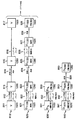
図8は、1つ以上の実施形態の処理を例示したブロック/流れ図である。また、図8には、相異なる実施形態相互間のトレードオフの一部が例示されている。 FIG. 8 is a block / flow diagram illustrating the processing of one or more embodiments. FIG. 8 illustrates some of the trade-offs between different embodiments.
図8には、ビデオを処理する処理系統810が含まれている。ビデオ映像(Video image)811は、1920の水平方向解像度を有している。しかしながら、処理系統810の送信フォーマットは、1280の水平方向解像度を有している。従って、ビデオ映像811は、処理812に於いて、フィルタ処理され、ダウン・サンプリングされて、1280の水平方向解像度を有するビデオ映像813が生成される。このフィルタ処理とダウン・サンプリングとは、処理系統810に於いて、一緒に行なわれる。しかしながら、別の実施形態では、このフィルタ処理とダウン・サンプリングとは、別々に行われる。フィルタ処理は、例えば、ビデオ映像811を低域濾波する為に行われるが、その目的は、ビデオ映像811をダウン・サンプリングする際のエイリアシングを防ぐ為である。ビデオ映像813は、送信及び/又は記憶(格納)処理814に送られる。
FIG. 8 includes a
系統810の受信側が、受信されたビデオ映像815にアクセスするが、この受信ビデオ映像815は、ビデオ映像813と同じであるか、類似しているか、或いは、異なることがあり得る。例えば、一実施形態に於いて、ビデオ映像815は、ビデオ映像813の記憶されたバージョンである。更に、別の一実施形態では、ビデオ映像815は、ソースの符号化処理と復号化処理(図示せず)後のビデオ映像813の再構成されたバージョンを表している。また、更に別の一実施形態では、ビデオ映像815は、チャンネルの符号化処理と復号化処理(誤り訂正を含む)(図示せず)後のビデオ映像813の誤り訂正されたバージョンを表している。ビデオ映像815はアップ・サンプリング処理816に於いて処理されて、元のビデオ映像811のように1920の水平方向解像度を有するビデオ映像817が生成される。
The receiving side of the
図8には、系統810に於いて処理される各ビデオ映像に対応する視差映像を処理する処理系統820も含まれている。視差映像(Disparity image)821が、1920の水平方向解像度を有しており、11520の解像度に基づく、整数値の視差値を含んでいる。尚、視差映像は、一般に、例えば、高密度視差マップ、ダウン・サンプリングされた視差マップ、或いは、希薄視差マップのような、視差情報の任意の集積を意味している。更に、視差マップは、例えば、画像、フレーム、フィールド、スライス、マクロブロック、パーティション、或いは、その他の視差情報の集合に対応することもある。
FIG. 8 also includes a
しかしながら、処理系統820の送信フォーマットは、1280の水平方向解像度を有している。従って、視差映像821は処理822に於いてフィルタ処理され、ダウン・サンプリングされて、1280の水平方向解像度を有する視差映像823が生成される。このフィルタ処理とダウン・サンプリングとは、処理系統820に於いて、一緒に行なわれる。しかしながら、別の実施形態では、このフィルタ処理とダウン・サンプリングとは、別々に行われる。フィルタ処理は、例えば、視差映像821の視差値を低域濾波する為に行われるが、その目的は、視差映像821をダウン・サンプリングする際のエイリアシングを防ぐ為である。
However, the transmission format of the
視差映像823の各視差値は、整数値である。これは、様々な方法で実現できる。一実施形態に於いて、フィルタ処理とダウン・サンプリングの各処理の結果は、最も近い整数に丸められる。別の一実施形態に於いて、あらゆる小数部分が、単純に、切り捨てられる。更に別の実施形態では、視差映像823の各視差値について浮動小数点表示を使用する。尚、フィルタ処理とダウン・サンプリングによって、視差映像823について1280の解像度が生成された後でも、各視差値は、まだ、11520の解像度に基づいている。
Each parallax value of the
視差映像823は、送信及び/又は記憶(格納)処理824に送られる。系統820の受信側が、受信された視差映像825にアクセスする。この視差映像825は、視差映像823と同じであるか、類似しているか、或いは、異なることがあり得る。例えば、一実施形態に於いて、視差映像825は、視差映像823の記憶されたバージョンである。更に、別の一実施形態では、視差映像825は、ソースの符号化処理と復号化処理(図示せず)後の視差映像823の再構成されたバージョンを表している。また、更に別の一実施形態では、視差映像825は、チャンネルの符号化処理と復号化処理(誤り訂正を含む)(図示せず)後の視差映像823の誤り訂正されたバージョンを表している。しかしながら、視差映像825に於ける各視差値は、必要ならば、例えば、丸め処理の使用によって、整数として残る。
The
視差映像825は、アップ・サンプリング処理826に於いて処理されて、元の視差映像821のように1920の水平方向解像度を有する視差映像827が生成される。処理826は、例えば、丸め処理または切り捨て処理によって、視差映像827についての整数値を生成する。
The
視差映像827の各視差値は、変換処理828に於いて、11520の解像度に基づくものから1920の解像度に基づくものに変換される。変換処理828は、前述の如く、各々の視差値を6により除算する。変換処理828によって、視差映像829が生成される。視差映像829の各視差値は、画素より細かい正確度を維持する為に、浮動小数点数として表される。
Each parallax value of the
処理系統820には少なくとも重要な利点が含まれていることは、明らかである。先ず第一に、各視差値は、最終的な視差映像829が得られるまで、系統820全体に亘って整数である。第二に、送信フォーマットの水平方向解像度が、ネイティブの視差マップ821の水平方向解像度と異なるにも拘わらず、実際の各視差値は、コード変換されない。従って、各視差値は、様々な相異なる水平方向解像度に適用できる。
It is clear that the
受信システムが、視差映像829を使用して、ビデオ映像817を処理する。この処理には、前述の如く、3D効果の調整、字幕の配置、グラフィックの挿入、或いは、視覚効果の提供が含まれることがある。
The receiving system processes the
図8には、比較の目的で、処理系統830も示されている。処理系統830も、系統810に於いて処理される各ビデオ映像に対応する各視差映像を処理する。処理系統830は、処理系統820の代わりと成り得るものである。以下に説明する如く、系統830の全体は、図8を簡略化する為に、示されていない。
FIG. 8 also shows a
視差映像831が1920の水平方向解像度を有し、そして、この視差映像831には、パーセンテージに基づく、浮動小数点表示を有する各視差値が含まれている。しかしながら、処理系統830の送信フォーマットは、1280の水平方向解像度を有している。従って、視差映像831は処理832に於いてフィルタ処理され、ダウン・サンプリングされて、1280の水平方向解像度を有する視差映像833が生成される。この処理832は、例えば、フィルタ処理及びダウン・サンプリングの処理812又は822と類似することがある。視差映像833の、パーセンテージに基づく各視差値は、引き続き、浮動小数点フォーマットで表される。
The
処理系統830の残りの部分(図示せず)は、処理系統820のそれと全く同じである。視差映像833は、送信及び/又は記憶(格納)処理に送られる。系統830の受信側が、受信された視差映像にアクセスする。この受信視差映像は、1920の水平方向解像度にアップ・サンプリングされ、そして次に、各視差値が、パーセンテージに基づくものから1920の解像度に基づくものに変換される。しかしながら、この変換処理は、前述の如く、1920×パーセンテージという乗算である。処理系統820とは対照的に、処理系統830に於ける各視差映像の各視差値は、常に、浮動小数点フォーマットで表される。
The rest of the processing system 830 (not shown) is exactly the same as that of the
図8には、比較の目的で、処理系統840も示されている。処理系統840も、系統810に於いて処理される各ビデオ映像に対応する各視差映像を処理する。処理系統840は、処理系統820の代わりと成り得るものである。以下に説明する如く、系統840の全体は、図8を簡略化する為に、示されていない。
FIG. 8 also shows a
視差映像841が1920の水平方向解像度を有し、そして、この視差映像841には、1920の解像度に基づく、浮動小数点表示を有する各視差値が含まれている。しかしながら、処理系統840の送信フォーマットは、1280の水平方向解像度を有している。従って、視差映像841は処理842に於いてフィルタ処理され、ダウン・サンプリングされて、1280の水平方向解像度を有する視差映像843が生成される。この処理842は、例えば、フィルタ処理及びダウン・サンプリングの処理812、822又は823と類似することがある。視差映像843の各視差値は、引き続き、浮動小数点フォーマットで表される。
The
次に、視差映像843の各視差値は変換処理850に於いて変換されて、視差映像860が生成される。この変換処理850は、各視差値を、1920の水平方向解像度に基づくものから1280の水平方向解像度に基づくものに変換する。視差映像860の各視差値は、引き続き、浮動小数点フォーマットで表される。
Next, each parallax value of the
処理系統840の残りの部分(図示せず)は、処理系統820のそれと全く同じである。視差映像860は、送信及び/又は記憶(格納)処理に送られる。系統840の受信側が、受信された視差映像にアクセスする。この受信視差映像は、1920の水平方向解像度にアップ・サンプリングされ、そして次に、各視差値が、1280の解像度に基づくものから1920の解像度に基づくものに変換される。この変換処理は、各視差値を1920/1280により乗算することを含む。処理系統830と同様に、また、処理系統820とは対照的に、処理系統840に於ける各視差映像の各視差値は、常に、浮動小数点フォーマットで表される。
The rest of the processing system 840 (not shown) is exactly the same as that of the
処理系統840の別の一実施形態に於いては、変換処理850は行われない。従って、視差映像843の各視差値は、1920の水平方向解像度に基づく視差値として残る。しかしながら、視差映像843の水平方向解像度は、1280として残る。従って、この実施形態では、送信の前の当該変換を回避して、受信後又は読み出し後の再変換を、何とかして、回避している。変換及び再変換を回避することによって、少なくとも一部の実施形態に於ける丸め誤差も回避される。この実施形態は、全てのその他の実施形態と同様に、各利点を有しており、そして有用であり得る。しかしながら、各視差値は、この実施形態全体を通じて、浮動小数点数で表される。
In another embodiment of the
次に、図9を参照すると、これまでに説明した各特徴と各原理とを適用できるビデオ送信システム又は装置900が示されている。ビデオ送信システム又は装置900は、例えば、衛星放送、ケーブル放送、電話回線放送、或いは、地上波放送のような種々の媒体のうちの任意のものを使用して信号を送信する、例えば、ヘッドエンド又は送信システムであってもよい。それに加えて、或いは、その代わりに、ビデオ送信システム又は装置900は、例えば、信号を供給して記憶する為に使用してもよい。当該送信は、インターネット、或いは、その他の何らかのネットワークを介して、行える。ビデオ送信システム又は装置900は、例えば、ビデオ・コンテンツと、例えば、各奥行き及び/又は各視差値を含む、例えば、奥行きの各インジケータのようなその他のコンテンツとを生成して配信できる。尚、図9の各ブロックが、ビデオ送信システム又は装置のブロック図を表していることに加えて、ビデオ送信処理の流れ図も表していることは、明らかである。
Referring now to FIG. 9, there is shown a video transmission system or
ビデオ送信システム又は装置900は、プロセッサ901から入力ビデオを受信する。一実施形態に於いて、プロセッサ901は、視差映像821、831、841及び/又はビデオ映像811のようなオリジナルの解像度の各映像をビデオ送信システム又は装置900に供給する。しかしながら、別の一実施形態に於いては、プロセッサ901は、例えば、処理812、822、832及び842について説明したように、フィルタ処理とダウン・サンプリングとを行い、ビデオ映像813及び/又は視差映像823、833、843のような各映像を生成するように構成されたプロセッサである。更に別の一実施形態に於いては、プロセッサ901は、例えば、処理850のような視差変換を行って、例えば、視差映像860のような、変換された各視差値を有する視差映像を生成するように構成されたプロセッサである。プロセッサ901は、例えば、入力映像の水平方向解像度と、各視差値が基づいている水平方向解像度と、各視差値がパーセンテージに基づいているのか、或いは、公倍数に基づいているのかと、1つ以上の入力映像についてのその他の情報とを示すメタデータも供給してもよい。
Video transmission system or
ビデオ送信システム又は装置900には、符号器902と、符号化信号を送信できる送信器904とが含まれている。符号器902は、プロセッサ901からビデオ情報を受信する。このビデオ情報には、例えば、ビデオ映像、及び/又は、視差(或いは、奥行き)映像が含まれていてもよい。符号器902は、ビデオ及び/又は視差の情報に基づいて、符号化信号を生成する。符号器902は、例えば、AVC符号器であってもよい。AVC符号器は、ビデオ情報と視差情報の両方に適用できる。AVCは、現在の国際標準化機構/国際電気標準機関(ISO/IEC)のムービング・ピクチャ・エキスパート・グループ―4(MPEG−4)第10部門のアドバンスト・ビデオ・コーディング(AVC)規格/国際電気通信連合、電気通信部門(ITU−T)のH.264の勧告(以下、「H.264/MPEG−4AVC規格」、或いは、その各変形である、例えば、「AVC規格」、「H.264規格」、或いは、単に、「AVC」又は「H.264」という)を意味する。
Video transmission system or
符号器902には、例えば、種々の情報を受信して、記憶処理または送信処理用に体系化されたフォーマットに組み立てる組み立て部を含む各サブ・モジュールが含まれている。この種々の情報には、例えば、符号化された、或いは、符号化されていないビデオと、符号化された、或いは、符号化されていない各視差(或いは、各奥行き)値と、例えば、各動きベクトル、各符号化方式インジケータ、及び、各シンタックス要素のような符号化された、或いは、符号化されていない各要素とが含まれることがある。幾つかの実施形態では、符号器902は、プロセッサ901を含み、従って、プロセッサ901の各処理を行なう。
送信器904は、符号器902から符号化信号を受信し、該符号化信号を1つ以上の出力信号に入れて送信する。送信器904は、例えば、符号化画像、及び/又は、それに関する情報を表す1つ以上のビットストリームを有するプログラム信号を送信するように構成されていてもよい。代表的な送信器は、例えば、誤り訂正符号化を行う機能、データを信号にインタリーブする機能、信号内でエネルギーをランダム化する機能、及び、変調器906を使用して信号を1つ以上の搬送波上に変調する機能のうちの1つ以上の機能を実行する。送信器904は、アンテナ(図示せず)を内蔵するか、或いは、アンテナに接続されていてもよい。更に、送信器904の実施形態は、変調器906に限定してもよい。
The
ビデオ送信システム又は装置900は、また、記憶部908にも通信可能に接続されている。一実施形態に於いて、記憶部908は、符号器902に接続されており、符号器902からの符号化ビットストリームを記憶(格納)する。別の一実施形態に於いては、記憶部908は、送信器904に接続されており、送信器904からのビットストリームを記憶(格納)する。送信器904からのビットストリームには、例えば、送信器904によって更に処理されている1つ以上の符号化ビットストリームが含まれていてもよい。記憶部908は、相異なる実施形態に於いて、標準的なDVD、ブルーレイ・ディスク、ハード・ドライブ、及び、その他の何らかの記憶装置のうちの1つ以上のものである。
The video transmission system or
次に、図10を参照すると、これまでに説明した各特徴と各原理とを適用できるビデオ受信システム又は装置1000が示されている。ビデオ受信システム又は装置1000は、例えば、衛星放送、ケーブル放送、電話回線放送、或いは、地上波放送のような種々の媒体を介して各信号を受信するように構成されていてもよい。これらの信号は、インターネット、或いは、その他の何らかのネットワークを介して受信されてもよい。尚、図10の各ブロックが、ビデオ受信システム又は装置のブロック図を提供していることに加えて、ビデオ受信処理の流れ図も提供していることは、明らかである。
Referring now to FIG. 10, there is shown a video receiving system or
ビデオ受信システム又は装置1000は、符号化ビデオを受信して、表示(例えばユーザへの表示)用、処理用、或いは、記憶用に、例えば、復号化ビデオ信号を提供する、例えば、セルホーン(携帯電話機)、コンピュータ、セットトップ・ボックス、テレビジョン、或いは、その他の装置であってよい。従って、ビデオ受信システム又は装置1000は、自己の出力を、例えば、テレビジョンのスクリーン、コンピュータのモニタ、コンピュータ(記憶、処理または表示用)、或いは、その他の何らかの記憶用、処理用または表示用の装置に提供してもよい。
A video receiving system or
ビデオ受信システム又は装置1000は、ビデオ情報を受信して処理することが出来、このビデオ情報には、例えば、各ビデオ映像、及び/又は、各視差(或いは、各奥行き)映像が含まれていてもよい。ビデオ受信システム又は装置1000には、例えば、本願の各実施形態に於いて説明した各信号のような符号化信号を受信する受信器1002が含まれている。受信器1002は、例えば、ビデオ映像815及び/又は視差映像825のうちの1つ以上のものを提供する信号、或いは、図9のビデオ送信システム900から出力された信号を受信してもよい。
The video receiving system or
受信器1002は、例えば、各符号化画像を表す複数のビットストリームを有するプログラム信号を受信するように構成されていてもよい。代表的な受信器は、例えば、変調符号化データ信号を受信する機能、復調器1004を使用して1つ以上の搬送波からデータ信号を復調する機能、信号内でエネルギーをデランダム化する機能、信号内でデータをデインタリーブする機能、及び、信号を誤り訂正復号化する機能のうちの1つ以上の機能を実行する。受信器1002は、アンテナ(図示せず)を内蔵するか、或いは、アンテナに接続されていてもよい。受信器1002の実施形態は、復調器1004に限定してもよい。
The
ビデオ受信システム又は装置1000には、復号器1006が含まれている。受信器1002は、復号器1006に受信信号を供給する。受信器1002が復号器1006に供給した信号には、1つ以上の符号化ビットストリームが含まれていてもよい。復号器1006は、例えば、ビデオ情報を含む各復号化ビデオ信号のような復号化信号を出力する。復号器1006は、例えば、AVC復号器であってもよい。
The video receiving system or
ビデオ受信システム又は装置1000は、また、記憶部1007にも通信可能に接続されている。一実施形態に於いて、記憶部1007は受信器1002に接続されており、受信器1002は、記憶部1007からビットストリームにアクセスする。別の一実施形態に於いては、記憶部1007は復号器1006に接続されており、復号器1006は、記憶部1007からビットストリームにアクセスする。記憶部1007からアクセスされたビットストリームには、相異なる実施形態に於いて、1つ以上の符号化ビットストリームが含まれている。記憶部1007は、相異なる実施形態に於いて、標準的なDVD、ブルーレイ・ディスク、ハード・ドライブ、及び、その他の何らかの記憶装置のうちの1つ以上のものである。
The video receiving system or
復号器1006からの出力ビデオは、一実施形態に於いて、プロセッサ1008に供給される。プロセッサ1008は、一実施形態に於いて、例えば、アップ・サンプリング処理816及び/又は826について説明したようなアップ・サンプリングを行うように構成されたプロセッサである。幾つかの実施形態に於いては、復号器1006が、プロセッサ1008を含み、従って、プロセッサ1008の処理を行なう。その他の各実施形態に於いては、プロセッサ1008は、例えば、セットトップ・ボックス、或いは、テレビジョンのようなダウンストリームの(下流の)装置の一部である。
The output video from
尚、少なくとも一実施形態に於いて、2つの視差マップの生成用に特別にもう1ビットが使用される。第1の視差マップは「左」ビューに関して算出され、第2の視差マップは「右」ビューに関して算出される。各オブジェクトが遮断される可能性がある場合、2つの視差マップを有することによって、各遮断に対する対処が改善される。例えば、対応する各視差値を比較することによって、当該システムは、遮断が存在するか否かを判定し、遮断が存在する場合、その不具合を解消する措置を講ずることが出来る。更に別の実施形態では、視差マップの数を増やし、その数の視差マップに適切な数のビットを割り当てる。例えば、MVC(MVC機能拡張を備えたAVCを意味する(属性G))のようなマルチ・ビューの場合では、あらゆるビューからその他のあらゆるビューに対する計算された視差を示す一組の視差マップを送ることが望ましい。或いは、一実施形態に於いては、一部のビューについて視差マップを送ればよい。 Note that in at least one embodiment, one extra bit is used specifically for the generation of two disparity maps. The first disparity map is calculated for the “left” view, and the second disparity map is calculated for the “right” view. If each object can be blocked, having two disparity maps improves handling for each block. For example, by comparing each corresponding disparity value, the system can determine whether there is a blockade, and if there is a blockage, can take measures to eliminate the deficiency. In yet another embodiment, the number of parallax maps is increased and an appropriate number of bits is assigned to that number of parallax maps. For example, in the case of multi-views such as MVC (meaning AVC with MVC extension (attribute G)), send a set of disparity maps indicating the calculated disparity from every view to every other view. It is desirable. Alternatively, in one embodiment, a disparity map may be sent for some views.
視差の計算は、例えば、動きベクトルの計算と同様に行うことが出来る。或いは、視差は、周知の如く、以下に説明するように、奥行き値からも計算できる。 The calculation of the parallax can be performed, for example, similarly to the calculation of the motion vector. Alternatively, as is well known, the parallax can also be calculated from the depth value, as will be described below.
種々の実施形態では、奥行き値の代わりに視差値を使用することによる利点がある。そのような利点には、(1)奥行き値が、無限になる可能性があり、従って、表現したり符号化したりすることが、より難しい一方、視差値は有界であること、及び、(2)潜在的に非常に大きい奥行き値は、それを表すのに対数のスケール変更が必要になる場合が多い一方、視差値は直接表すことが出来ることが含まれる。また、視差から奥行きを特定することは、一般に、簡単である。種々の実施形態に於いては、メタデータを使用して、焦点距離、基線距離(長)、及び、集束面距離のような情報を提供する。集束面距離は、各カメラが集束している時に、各カメラ軸が互いに交差する距離である。各カメラ軸が互いに交差する点は、図4に於いて、角度410の頂点(角頂)として示されている。各カメラが互いに平行である時、集束面距離は、無限大の距離である。
Various embodiments benefit from using disparity values instead of depth values. Such advantages include: (1) the depth value can be infinite and therefore more difficult to represent and encode, while the disparity value is bounded, and ( 2) Potentially very large depth values often require logarithmic scaling to represent it, while disparity values can be represented directly. Also, it is generally easy to specify the depth from the parallax. In various embodiments, metadata is used to provide information such as focal length, baseline distance (long), and focal plane distance. The focusing plane distance is a distance at which the camera axes intersect each other when the cameras are focused. The point where each camera axis intersects with each other is shown as the apex (angle apex) of the
上述の如く、特定の各特徴と各様相とを有する1つ以上の実施形態が提供される。特に、高密度の視差マップに関連した幾つかの実施形態が提供される。高密度の視差マップによって、例えば、家庭用機器での比較的複雑な3D効果の調整、及び、ポスト・プロダクション段階に於ける比較的簡単な字幕配置のような様々な応用例が可能になる。しかしながら、これらの実施形態の変形例と別の応用例が考えられ、そして、以上説明した各実施形態の各特徴と各様相は、各開示事項の範囲内で、その他の実施形態にも転用できる。 As described above, one or more embodiments are provided having specific features and aspects. In particular, several embodiments relating to high density parallax maps are provided. A high density parallax map allows for various applications such as, for example, adjusting relatively complex 3D effects in home appliances and relatively simple subtitle placement in the post-production stage. However, modifications and other application examples of these embodiments are conceivable, and each feature and aspect of each embodiment described above can be diverted to other embodiments within the scope of each disclosure. .
尚、1つ以上の特定のディスプレイ・サイズについての+80画素から−150画素の範囲は、上述の各実施形態のうちの少なくとも1つの実施形態に使用される。しかしながら、その他の実施形態では、それらの特定のディスプレイ・サイズについてさえも、範囲の両端、及び/又は、範囲の自体のサイズが変わった別の視差範囲が使用される。一実施形態に於いて、テーマ・パークでの提示では、より劇的な効果を得る為に、(例えば、スクリーンから飛び出して今にも近づいて来そうなオブジェクトを表現する為に)より厳格な負の視差が使用される。別の一実施形態では、営業用機器が、家庭用機器よりも広い視差範囲をサポートする。 Note that a range of +80 pixels to −150 pixels for one or more specific display sizes is used for at least one of the embodiments described above. However, in other embodiments, even for those particular display sizes, different parallax ranges are used that vary at either end of the range and / or the size of the range itself. In one embodiment, the presentation at the theme park has a more stringent negative (for example, to represent an object that is about to jump out of the screen and come closer) to have a more dramatic effect. Parallax is used. In another embodiment, the business device supports a wider parallax range than the home device.
本願明細書に記載の各実施形態及び各特徴の幾つかのものは、AVC規格、及び/又は、MVC機能拡張(属性H)を備えたAVC、及び/又は、SVC機能拡張(属性G)を備えたAVCの場合にも使用できる。更に、これらの各実施形態と各特徴は、その他の(既存の、又は、将来の)規格の場合にも、或いは、所定の規格を伴わない場合にも使用できる。 Each of the embodiments and features described herein includes an AVC standard and / or an AVC with an MVC extension (attribute H) and / or an SVC function extension (attribute G). It can also be used in the case of the provided AVC. Furthermore, each of these embodiments and features can be used in the case of other (existing or future) standards or in the case where no predetermined standard is involved.
本願発明の各原理の「一実施例」、「ある実施例」、「一実施形態」、或いは、「ある実施形態」、また、それらの異形に対する言及は、その実施例(実施形態)について説明した特定の特徴、構成、特性等が本原理の少なくとも1つの実施例(実施形態)に含まれていることを意味する。従って、本願明細書全体を通して様々な箇所に記載された「一実施例に於いて」、「ある実施例に於いて」、「一実施形態に於いて」、或いは、「ある実施形態に於いて」なる表現、また、それらの異形の表現は、必ずしも、全てが、同一の実施例(実施形態)を示している訳ではない。 Reference to “one example”, “one example”, “one embodiment”, or “one embodiment” of each principle of the invention of the present application, and variants thereof, describes the example (embodiment). It is meant that the specific features, configurations, characteristics, etc., are included in at least one example (embodiment) of the present principles. Thus, in various places throughout this application, “in an embodiment”, “in an embodiment”, “in an embodiment”, or “in an embodiment” The expressions "" and their variants are not necessarily all referring to the same example (embodiment).
更に、本願に於いて、或いは、本願の特許請求の範囲に於いて、種々の情報を「特定する」という場合がある。情報を特定することには、例えば、情報を推定すること、情報を算出すること、情報を予測すること、及び、メモリから情報を検索すること、のうちの1つ以上のことが含まれる。 Furthermore, in the present application or in the claims of the present application, various information may be “specified”. Identifying information includes, for example, one or more of estimating information, calculating information, predicting information, and retrieving information from memory.
所与の一つのディスプレイが複数の相異なる解像度をサポートしている場合がある。その所与のディスプレイは、例えば、1280、1440、或いは、1920の解像度を有するビデオ・コンテンツを表示できる場合がある。それにも拘わらず、その所与のディスプレイは、サポートする最高解像度が1920であるから、1920ディスプレイと呼ばれることが多い。大きなディスプレイが小さな解像度の映像を表示している時、映像の個別の構成要素が複数の画素で構成されている場合がある。例えば、ディスプレイが800と1920の水平方向解像度をサポートできるならば、そのディスプレイの幅は、一般に、少なくとも1920画素ある。そのディスプレイが800の解像度の映像を表示している時、そのディスプレイが、映像の各々の構成要素に対して、少なくとも、3つ以上の画素から成る部分を割り当てている可能性がある。 A given display may support multiple different resolutions. The given display may be able to display video content having a resolution of, for example, 1280, 1440, or 1920. Nevertheless, the given display is often referred to as a 1920 display because the highest resolution it supports is 1920. When a large display is displaying a video with a small resolution, individual components of the video may be composed of a plurality of pixels. For example, if a display can support 800 and 1920 horizontal resolutions, the width of the display is typically at least 1920 pixels. When the display is displaying an 800 resolution video, the display may assign at least a portion of three or more pixels to each component of the video.
種々の実施形態では、各視差値の浮動小数点表示が使用される。それらの実施形態の特定の変形例では、各視差値の固定小数点表示が、浮動小数点表示の代わりに、使用される。 In various embodiments, a floating point representation of each disparity value is used. In certain variations of those embodiments, a fixed point representation of each disparity value is used instead of a floating point representation.
例えば、「A/B」、「A及び/又はB」、及び、「AとBの少なくとも1つ」の場合の「/」、「及び/又は」、及び、「・・・の少なくとも1つ」の何れかの使用は、1番目に記載のオプション(A)のみの選択、2番目に記載のオプション(B)のみの選択、或いは、両方のオプション(AとB)の選択を包含することを意図している。更なる例として、「A、B、及び/又は、C」と「A、B、及び、Cの少なくとも1つ」と「A、B、或いは、Cの少なくとも1つ」の場合、そのような記載は、1番目に記載のオプション(A)のみの選択、2番目に記載のオプション(B)のみの選択、3番目に記載のオプション(C)のみの選択、1番目と2番目に記載のオプション(AとB)のみの選択、1番目と3番目に記載のオプション(AとC)のみの選択、2番目と3番目に記載のオプション(BとC)のみの選択、或いは、3つのオプション(AとBとC)の選択を包含することを意図している。このことは、当業者に直ちに明らかなように、多数の項目が記載される場合にも拡張できる。 For example, in the case of “A / B”, “A and / or B”, and “at least one of A and B”, at least one of “/”, “and / or”, and “. Use of the first option (A) only includes selection of the second option (B) only, or includes both options (A and B). Is intended. As a further example, in the case of “A, B, and / or C” and “at least one of A, B, and C” and “at least one of A, B, or C”, such as The description is the selection of only the first option (A), the selection of the second option (B) only, the selection of the third option (C) only, the first and second descriptions Select only options (A and B), select only the first and third options (A and C), select only the second and third options (B and C), or select three It is intended to encompass the selection of options (A, B and C). This can be extended to many items as will be readily apparent to those skilled in the art.
更に、多くの実施形態が、符号器(例えば、符号器902)、復号器(例えば、復号器1006)、復号器からの出力を処理するポストプロセッサ(例えば、プロセッサ1008)、及び、符号器に入力を供給するプリプロセッサ(例えば、プロセッサ901)のうちの1つ以上のもので、実施され得る。更に、その他の実施形態も、この開示事項によって、考えられる。 Further, many embodiments include an encoder (eg, encoder 902), a decoder (eg, decoder 1006), a post processor (eg, processor 1008) that processes the output from the decoder, and an encoder. It can be implemented with one or more of the preprocessors (eg, processor 901) that provide the input. Still other embodiments are contemplated by this disclosure.
ここに記載した各実施形態は、例えば、方法またはプロセス、装置、ソフトウェア・プログラム、データ・ストリーム、或いは、信号に於いて、実施し得る。各特徴の実施形態は、たとえ信号の実施形態の文脈で説明されていても(例えば、方法としてのみ説明されていても)、その他の形態(例えば、装置またはプログラム)に於いても実施し得る。装置は、例えば、適切なハードウェア、ソフトウェア、及び、ファームウェアに於いて、実施し得る。方法は、例えば、コンピュータ、マイクロプロセッサ、集積回路、或いは、プログラム可能論理デバイスを含む、一般に処理装置を意味する、例えば、プロセッサのような、例えば、装置に於いて、実施し得る。プロセッサには、例えば、コンピュータ、携帯電話(セル・ホーン)、ポータブル/パーソナル・ディジタル・アシスタント(「PDA」)、及び、エンド・ユーザ相互間の情報通信を容易にするその他の装置のような通信装置も含まれる。 Each of the embodiments described herein may be implemented, for example, in a method or process, an apparatus, a software program, a data stream, or a signal. Each feature embodiment may be implemented in the context of a signal embodiment (e.g., described only as a method) or in other forms (e.g., an apparatus or program). . The device can be implemented, for example, in suitable hardware, software, and firmware. The method may be implemented in, for example, an apparatus, eg, a processor, typically meaning a processing unit, including, for example, a computer, a microprocessor, an integrated circuit, or a programmable logic device. Processors include communications such as computers, cell phones (cell horns), portable / personal digital assistants ("PDAs"), and other devices that facilitate information communication between end users. A device is also included.
ここに記載した種々の処理と特徴の実施は、様々な相異なる機器、或いは、アプリケーションに於いて具現化し得、特に、例えば、データ符号化、データ復号化、ビュー生成、奥行き又は視差処理、及び、各映像とそれに関する奥行き及び/又は視差マップとのその他の処理に関連する機器、或いは、アプリケーションに於いて具現化し得る。そのような機器の例には、符号器、復号器、復号器からの出力を処理するポストプロセッサ、符号器に入力を供給するプリプロセッサ、ビデオ符号器、ビデオ復号器、ビデオ・コーデック、ウェブ・サーバ、セットトップ・ボックス、ラップトップ、パーソナル・コンピュータ、携帯電話(セル・ホーン)、PDA、及び、その他の通信デバイスが含まれる。当該機器が、モバイルでもよく、また、移動車両に装備されてもよいことは明らかである。 The implementation of the various processes and features described herein may be implemented in a variety of different devices or applications, in particular, for example, data encoding, data decoding, view generation, depth or disparity processing, and It can be embodied in a device or application related to other processing of each image and its related depth and / or disparity map. Examples of such equipment include encoders, decoders, postprocessors that process the output from the decoders, preprocessors that provide input to the encoders, video encoders, video decoders, video codecs, web servers , Set-top boxes, laptops, personal computers, cell phones (cell horns), PDAs, and other communication devices. Obviously, the device may be mobile or equipped on a moving vehicle.
更に、方法は、プロセッサによって実行される各命令によって実施し得、そのような各命令(及び/又は、一実施形態によって生成される各データ値)はプロセッサ読み取り可能媒体上に格納でき、そのようなプロセッサ読み取り可能媒体は、例えば、集積回路、ソフトウェア搬送デバイス、或いは、その他の記憶デバイスであり、そのようなデバイスは、例えば、ハードディスク、コンパクト・ディスケット(「CD」)、光ディスク(例えば、しばしば、デジタル多用途ディスク又はデジタル・ビデオ・ディスクと呼ばれるDVDのような光ディスク)、ランダム・アクセス・メモリ(「RAM」)、或いは、リード・オンリー・メモリ(「ROM」)である。各命令は、プロセッサ読み取り可能媒体に具体的に実施されるアプリケーション・プログラムを構成してもよい。各命令は、例えば、ハードウェア、ファームウェア、ソフトウェア、或いは、それらの組み合わせに於いて、存在してもよい。各命令は、例えば、オペレーティング・システム、別個のアプリケーション、或いは、両者の組み合わせに於いて、存在してもよい。従って、プロセッサは、例えば、処理を実行するように構成された装置と、処理を実行する為の各命令を含むプロセッサ読み取り可能媒体を備えた装置(例えば、記憶装置)の両方として、特徴付けてもよい。更に、プロセッサ読み取り可能媒体は、各命令に加えて、或いは、各命令に代えて、一実施形態によって生成される各データ値を格納してもよい。 Further, the method may be implemented by instructions executed by a processor, and each such instruction (and / or each data value generated by one embodiment) may be stored on a processor readable medium, and so on. Such processor readable media are, for example, integrated circuits, software transport devices, or other storage devices, such as hard disks, compact diskettes ("CDs"), optical disks (eg, often A digital versatile disc or an optical disc such as a DVD called a digital video disc), a random access memory (“RAM”), or a read only memory (“ROM”). Each instruction may constitute an application program that is specifically implemented on a processor-readable medium. Each instruction may be present, for example, in hardware, firmware, software, or a combination thereof. Each instruction may be present, for example, in the operating system, a separate application, or a combination of both. Thus, a processor can be characterized, for example, as both a device configured to perform processing and a device (eg, a storage device) with a processor-readable medium that includes instructions for performing the processing. Also good. Further, a processor-readable medium may store each data value generated by an embodiment in addition to or instead of each instruction.
当業者には明白であるが、各実施形態によって、例えば、記憶されるか、或いは、送信されるであろう情報を伝達するようにフォーマット化された様々な信号が生成され得る。その情報には、例えば、方法を実施する為の各命令、或いは、既に説明した各実施形態のうちの1つによって生成されたデータが含まれ得る。例えば、信号は、既に説明した実施例のシンタックスを書くか、或いは、読む為の各規則をデータとして搬送するようにフォーマット化されてもよいし、或いは、既に説明した実施例によって書かれた実際のシンタックス値をデータとして搬送するようにフォーマット化されてもよい。そのような信号は、例えば、電磁波として(例えば、スペクトルの無線周波数部分を使用して)、或いは、ベースバンド信号としてフォーマット化されてもよい。そのフォーマット化には、例えば、データ・ストリームを符号化すること、及び、搬送波を符号化データ・ストリームで変調することが含まれてもよい。信号が搬送する情報は、例えば、アナログ情報であっても、或いは、デジタル情報であってもよい。その信号は、周知の如く、様々な相異なる有線、或いは、無線のリンクを介して、送信されてもよい。その信号は、プロセッサ読み取り可能媒体上に格納されてもよい。 As will be apparent to those skilled in the art, each embodiment may generate a variety of signals formatted to convey information that may be stored or transmitted, for example. The information may include, for example, each instruction for performing the method, or data generated by one of the previously described embodiments. For example, the signal may be formatted to carry the syntax of the previously described embodiment, or to carry each rule for reading as data, or written by the previously described embodiment. It may be formatted to carry actual syntax values as data. Such a signal may be formatted, for example, as an electromagnetic wave (eg, using the radio frequency portion of the spectrum) or as a baseband signal. The formatting may include, for example, encoding the data stream and modulating the carrier with the encoded data stream. The information carried by the signal may be analog information or digital information, for example. The signal may be transmitted over a variety of different wired or wireless links, as is well known. The signal may be stored on a processor readable medium.
以上、多数の実施形態を説明した。しかしながら、種々の修正を行うことが出来る。例えば、相異なる実施形態の各構成要素を組み合わせて、或いは、補足して、或いは、修正して、或いは、取り除いて、別の実施形態を提供してもよい。更に、当業者であれば理解できることであるが、その他の構造と処理を上述のものに代えることが出来、その結果得られる各実施形態は、上述の各実施形態と少なくとも実質的に同じ態様で、少なくとも実質的に同じ機能を果たして、少なくとも実質的に同じ効果を達成するであろう。従って、上述の各実施形態、及び、その他の各実施形態が本願発明によって考えられる。 A number of embodiments have been described above. However, various modifications can be made. For example, each component of different embodiments may be combined, supplemented, modified, or removed to provide another embodiment. Further, those skilled in the art will appreciate that other structures and processes can be substituted for those described above, and that the resulting embodiments are at least substantially the same as the above-described embodiments. Will perform at least substantially the same function and achieve at least substantially the same effect. Therefore, the above-described embodiments and other embodiments are conceivable by the present invention.
Claims (9)
画像内の特定の箇所についての視差値であり、前記画像の水平方向解像度に対する視差を示す前記視差値にアクセスするステップと、
前記画像の前記水平方向解像度に対する参照解像度の比により、前記アクセスした視差値をスケール変更することで、修正視差値を生成するステップと、
を含み、
前記修正視差値は、前記参照解像度に対する視差を示し、
前記参照解像度は、前記画像の前記水平方向解像度および前記画像が表示される解像度よりも高く、前記参照解像度は複数の解像度の最小公倍数に対応する、前記方法。 A method,
Accessing the parallax value for a particular location in the image and indicating the parallax for the horizontal resolution of the image;
More specific reference resolution for the horizontal resolution of the image, the disparity value the access by scaling, and generating a modified disparity value,
Including
The modified parallax value indicates parallax with respect to the reference resolution;
The reference resolution, wherein the horizontal resolution and the image is rather higher than the resolution displayed image, the reference resolution corresponding to a plurality of resolutions least common multiple, said method.
画像内の特定の箇所についての視差値であり、前記画像の水平方向解像度に対する視差を示す前記視差値にアクセスする手段と、
前記画像の前記水平方向解像度に対する参照解像度の比により、前記アクセスした視差値をスケール変更することで、修正視差値を生成する手段と、
を備え、
前記修正視差値は、前記参照解像度に対する視差を示し、
前記参照解像度は、前記画像の前記水平方向解像度および前記画像が表示される解像度よりも高く、前記参照解像度は複数の解像度の最小公倍数に対応する、前記装置。 A device,
Means for accessing the parallax value for a specific location in the image and indicating the parallax with respect to a horizontal resolution of the image;
More reference resolution ratio with respect to the horizontal resolution of the image, the disparity value the access by scaling means for generating a modified disparity value,
With
The modified parallax value indicates parallax with respect to the reference resolution;
The reference resolution, wherein the horizontal resolution and the image is rather higher than the resolution displayed image, the reference resolution corresponding to a plurality of resolutions least common multiple, the device.
前記命令によって、1つ以上のプロセッサが、
画像内の特定の箇所についての視差値であり、前記画像の水平方向解像度に対する視差を示す前記視差値にアクセスするステップと、
前記画像の前記水平方向解像度に対する参照解像度の比により、前記アクセスした視差値をスケール変更することで、修正視差値を生成するステップと、
を集合的に行い、
前記修正視差値は、前記参照解像度に対する視差を示し、
前記参照解像度は、前記画像の前記水平方向解像度および前記画像が表示される解像度よりも高く、前記参照解像度は複数の解像度の最小公倍数に対応する、前記プロセッサ読み取り可能媒体。 A processor readable medium having instructions stored thereon,
The instructions cause one or more processors to
Accessing the parallax value for a particular location in the image and indicating the parallax for the horizontal resolution of the image;
More specific reference resolution for the horizontal resolution of the image, the disparity value the access by scaling, and generating a modified disparity value,
Is performed collectively,
The modified parallax value indicates parallax with respect to the reference resolution;
The reference resolution, wherein the horizontal resolution and the image is rather higher than the resolution displayed image, the reference resolution corresponding to a plurality of resolutions least common multiple, the processor-readable medium.
第1の解像度を有する画像内の特定の箇所についての視差値であり、前記第1の解像度よりも高い参照解像度に対する視差を示す前記視差値にアクセスするステップと、
前記参照解像度に対する前記第1の解像度の比により、前記アクセスした視差値をスケール変更することで、前記第1の解像度に対する視差を示す修正視差値を生成するステップと、
を含み、前記参照解像度は複数の解像度の最小公倍数に対応する、前記方法。 A method,
Accessing the disparity value that is a disparity value for a specific location in an image having a first resolution and that indicates a disparity with respect to a reference resolution higher than the first resolution;
And generating the more the ratio of the first resolution, a disparity value the access by scaling, modifications disparity value indicating disparity with respect to the first resolution for the reference resolution,
Only including, the reference resolution corresponding to a plurality of resolutions least common multiple, said method.
第1の解像度を有する画像内の特定の箇所についての視差値であり、前記第1の解像度よりも高い参照解像度に対する視差を示す前記視差値にアクセスする手段と、
前記参照解像度に対する前記第1の解像度の比により、前記アクセスした視差値をスケール変更することで、前記第1の解像度に対する視差を示す修正視差値を生成する手段と、
を備え、前記参照解像度は複数の解像度の最小公倍数に対応する、前記装置。 A device,
Means for accessing the parallax value indicating a parallax value for a specific location in an image having a first resolution and indicating a parallax with respect to a reference resolution higher than the first resolution;
More to the ratio of said first resolution to said reference resolution, a disparity value the access by scaling means for generating a correction parallax value indicating a parallax with respect to said first resolution,
The reference resolution corresponds to a least common multiple of a plurality of resolutions .
前記命令によって、1つ以上のプロセッサが、
第1の解像度を有する画像内の特定の箇所についての視差値であり、前記第1の解像度よりも高い参照解像度に対する視差を示す前記視差値にアクセスするステップと、
前記参照解像度に対する前記第1の解像度の比により、前記アクセスした視差値をスケール変更することで、前記第1の解像度に対する視差を示す修正視差値を生成するステップと、
を集合的に行い、前記参照解像度は複数の解像度の最小公倍数に対応する、前記プロセッサ読み取り可能媒体。 A processor readable medium having instructions stored thereon,
The instructions cause one or more processors to
Accessing the disparity value that is a disparity value for a specific location in an image having a first resolution and that indicates a disparity with respect to a reference resolution higher than the first resolution;
And generating the more the ratio of the first resolution, a disparity value the access by scaling, modifications disparity value indicating disparity with respect to the first resolution for the reference resolution,
Collectively they have rows, the reference resolution corresponding to a plurality of resolutions least common multiple, the processor-readable medium.
Applications Claiming Priority (5)
| Application Number | Priority Date | Filing Date | Title |
|---|---|---|---|
| US31956610P | 2010-03-31 | 2010-03-31 | |
| US61/319,566 | 2010-03-31 | ||
| US39741810P | 2010-06-11 | 2010-06-11 | |
| US61/397,418 | 2010-06-11 | ||
| PCT/IB2011/000708 WO2011121437A1 (en) | 2010-03-31 | 2011-03-31 | 3d disparity maps |
Publications (3)
| Publication Number | Publication Date |
|---|---|
| JP2013524608A JP2013524608A (en) | 2013-06-17 |
| JP2013524608A5 JP2013524608A5 (en) | 2014-05-08 |
| JP6073214B2 true JP6073214B2 (en) | 2017-02-01 |
Family
ID=44246501
Family Applications (1)
| Application Number | Title | Priority Date | Filing Date |
|---|---|---|---|
| JP2013501979A Active JP6073214B2 (en) | 2010-03-31 | 2011-03-31 | Method, apparatus and processor readable medium for processing parallax |
Country Status (10)
| Country | Link |
|---|---|
| US (1) | US10791314B2 (en) |
| EP (1) | EP2553933B1 (en) |
| JP (1) | JP6073214B2 (en) |
| KR (1) | KR101825761B1 (en) |
| CN (2) | CN102934451B (en) |
| AU (1) | AU2011234163B2 (en) |
| CA (1) | CA2795021C (en) |
| HK (1) | HK1182245A1 (en) |
| MX (1) | MX340111B (en) |
| WO (1) | WO2011121437A1 (en) |
Families Citing this family (24)
| Publication number | Priority date | Publication date | Assignee | Title |
|---|---|---|---|---|
| CA2795021C (en) * | 2010-03-31 | 2020-06-16 | Thomson Licensing | 3d disparity maps |
| US20130128003A1 (en) * | 2010-08-19 | 2013-05-23 | Yuki Kishida | Stereoscopic image capturing device, and stereoscopic image capturing method |
| TWI475515B (en) * | 2011-04-13 | 2015-03-01 | Univ Nat Taiwan | Method for generating disparity map of stereo video |
| KR101810845B1 (en) | 2011-05-26 | 2017-12-22 | 톰슨 라이센싱 | Scale-independent maps |
| KR20140120000A (en) * | 2013-04-01 | 2014-10-13 | 한국전자통신연구원 | Device and method for producing stereoscopic subtitles by analysing three-dimensional space |
| US9460855B2 (en) * | 2013-10-01 | 2016-10-04 | Samsung Electro-Mechanics Co., Ltd. | Multilayer ceramic capacitor and board having the same |
| US10244223B2 (en) | 2014-01-10 | 2019-03-26 | Ostendo Technologies, Inc. | Methods for full parallax compressed light field 3D imaging systems |
| KR101882931B1 (en) | 2014-07-10 | 2018-07-30 | 삼성전자주식회사 | Multi view image display apparatus and disparity estimation method of thereof |
| CN105323573B (en) * | 2014-07-16 | 2019-02-05 | 北京三星通信技术研究有限公司 | 3-D image display device and method |
| TWI556624B (en) * | 2014-07-18 | 2016-11-01 | 友達光電股份有限公司 | Image displaying method and image dispaly device |
| CN105491277B (en) * | 2014-09-15 | 2018-08-31 | 联想(北京)有限公司 | Image processing method and electronic equipment |
| JP6205069B2 (en) * | 2014-12-04 | 2017-09-27 | エスゼット ディージェイアイ テクノロジー カンパニー リミテッドSz Dji Technology Co.,Ltd | Imaging system and method |
| JP6866299B2 (en) | 2015-04-23 | 2021-04-28 | オステンド・テクノロジーズ・インコーポレーテッド | Methods and equipment for omnidirectional parallax light field display systems |
| WO2016172385A1 (en) | 2015-04-23 | 2016-10-27 | Ostendo Technologies, Inc. | Methods for full parallax compressed light field synthesis utilizing depth information |
| US10448030B2 (en) | 2015-11-16 | 2019-10-15 | Ostendo Technologies, Inc. | Content adaptive light field compression |
| US10453431B2 (en) | 2016-04-28 | 2019-10-22 | Ostendo Technologies, Inc. | Integrated near-far light field display systems |
| US11051039B2 (en) | 2017-06-02 | 2021-06-29 | Ostendo Technologies, Inc. | Methods for full parallax light field compression |
| US20180350038A1 (en) | 2017-06-02 | 2018-12-06 | Ostendo Technologies, Inc. | Methods and Systems for Light Field Compression With Residuals |
| US10432944B2 (en) | 2017-08-23 | 2019-10-01 | Avalon Holographics Inc. | Layered scene decomposition CODEC system and methods |
| CN107436500B (en) * | 2017-08-25 | 2020-04-24 | 京东方科技集团股份有限公司 | Grating, preparation method, driving method and naked eye three-dimensional display system |
| US10931956B2 (en) * | 2018-04-12 | 2021-02-23 | Ostendo Technologies, Inc. | Methods for MR-DIBR disparity map merging and disparity threshold determination |
| US11172222B2 (en) | 2018-06-26 | 2021-11-09 | Ostendo Technologies, Inc. | Random access in encoded full parallax light field images |
| US11182630B2 (en) | 2019-03-29 | 2021-11-23 | Advanced New Technologies Co., Ltd. | Using an illumination sequence pattern for biometric authentication |
| US20200314411A1 (en) * | 2019-03-29 | 2020-10-01 | Alibaba Group Holding Limited | Synchronizing an illumination sequence of illumination sources with image capture in rolling shutter mode |
Family Cites Families (56)
| Publication number | Priority date | Publication date | Assignee | Title |
|---|---|---|---|---|
| US5025325A (en) * | 1989-10-13 | 1991-06-18 | Hewlett-Packard Company | Graphics scaling method for high resolution printers |
| JPH0818954A (en) * | 1994-06-24 | 1996-01-19 | Sharp Corp | Image transmitter |
| US5926567A (en) * | 1995-03-01 | 1999-07-20 | Compaq Computer Corporation | Method and apparatus for storing and rapidly displaying graphic data |
| CN1132123A (en) | 1995-03-25 | 1996-10-02 | 国营无锡市新峰石化管件厂 | Processing tech for short radius elbow |
| US6384859B1 (en) * | 1995-03-29 | 2002-05-07 | Sanyo Electric Co., Ltd. | Methods for creating an image for a three-dimensional display, for calculating depth information and for image processing using the depth information |
| JPH11127339A (en) * | 1997-10-23 | 1999-05-11 | Fuji Xerox Co Ltd | Image processor |
| US7092003B1 (en) | 1999-01-21 | 2006-08-15 | Mel Siegel | 3-D imaging arrangements |
| TW421969B (en) | 1999-03-19 | 2001-02-11 | Asustek Comp Inc | 3D image processing device and method |
| JP2000321050A (en) | 1999-05-14 | 2000-11-24 | Minolta Co Ltd | Method and apparatus for acquiring three-dimensional data |
| US20020145610A1 (en) | 1999-07-16 | 2002-10-10 | Steve Barilovits | Video processing engine overlay filter scaler |
| TW452757B (en) | 1999-08-17 | 2001-09-01 | Trumpion Microelectronics Inc | Image processing device in accordance with the resolution adjustment of flat panel display |
| JP2001306287A (en) * | 2000-04-25 | 2001-11-02 | Ricoh Co Ltd | Substitute printing system between printers different in machine kind |
| JP3736379B2 (en) * | 2001-04-19 | 2006-01-18 | ソニー株式会社 | Digital watermark embedding processing device, digital watermark detection processing device, digital watermark embedding processing method, digital watermark detection processing method, program storage medium, and program |
| US6873717B2 (en) * | 2002-07-09 | 2005-03-29 | Riverain Medical Group, Llc | Input/output interface for computer aided diagnosis (CAD) system |
| KR100439341B1 (en) | 2002-08-27 | 2004-07-07 | 한국전자통신연구원 | Depth of field adjustment apparatus and method of stereo image for reduction of visual fatigue |
| KR100768837B1 (en) | 2003-04-17 | 2007-10-19 | 샤프 가부시키가이샤 | 3-dimensional image creating apparatus, 3-dimensional image reproducing apparatus, 3-dimensional image processing apparatus, and recording medium recorded with 3-dimensional image processing program |
| JP4251907B2 (en) | 2003-04-17 | 2009-04-08 | シャープ株式会社 | Image data creation device |
| JP2005073049A (en) * | 2003-08-26 | 2005-03-17 | Sharp Corp | Device and method for reproducing stereoscopic image |
| US20050132191A1 (en) | 2003-12-16 | 2005-06-16 | Joshi Ajit P. | Method for authenticating different rendering devices with different service providers |
| DE602005027379D1 (en) | 2004-10-26 | 2011-05-19 | Koninkl Philips Electronics Nv | disparity |
| KR100636221B1 (en) | 2005-01-29 | 2006-10-19 | 삼성전자주식회사 | Method of selecting a content and reproducing/recording the same and an apparatus thereof |
| KR100727940B1 (en) | 2005-06-22 | 2007-06-14 | 삼성전자주식회사 | Method for adjusting quality of 3D stereo image using communication channel |
| KR100667810B1 (en) | 2005-08-31 | 2007-01-11 | 삼성전자주식회사 | Apparatus for controlling depth of 3d picture and method therefor |
| EP1952199B1 (en) | 2005-11-17 | 2012-10-03 | Nokia Corporation | Method and devices for generating, transferring and processing three-dimensional image data |
| US7738712B2 (en) | 2006-01-04 | 2010-06-15 | Aten International Co., Ltd. | Mixing 2-D gradient-difference and interpolation/decimation method and device for scaling a digital image |
| US8044994B2 (en) | 2006-04-04 | 2011-10-25 | Mitsubishi Electric Research Laboratories, Inc. | Method and system for decoding and displaying 3D light fields |
| US7609906B2 (en) | 2006-04-04 | 2009-10-27 | Mitsubishi Electric Research Laboratories, Inc. | Method and system for acquiring and displaying 3D light fields |
| US7916934B2 (en) | 2006-04-04 | 2011-03-29 | Mitsubishi Electric Research Laboratories, Inc. | Method and system for acquiring, encoding, decoding and displaying 3D light fields |
| JP4875162B2 (en) | 2006-10-04 | 2012-02-15 | コーニンクレッカ フィリップス エレクトロニクス エヌ ヴィ | Image enhancement |
| KR101311896B1 (en) | 2006-11-14 | 2013-10-14 | 삼성전자주식회사 | Method for shifting disparity of three dimentions and the three dimentions image apparatus thereof |
| US20080136819A1 (en) * | 2006-12-11 | 2008-06-12 | Michael Shivas | Apparatus and method for screen scaling displays on communication devices |
| JP4936869B2 (en) * | 2006-12-12 | 2012-05-23 | 株式会社東芝 | Image processing apparatus and image processing method |
| JP4909063B2 (en) | 2006-12-28 | 2012-04-04 | キヤノン株式会社 | Imaging apparatus and image recording method |
| KR20080076628A (en) | 2007-02-16 | 2008-08-20 | 삼성전자주식회사 | Image display device for improving three-dimensional effect of stereo-scopic image and method thereof |
| KR100778085B1 (en) | 2007-03-14 | 2007-11-22 | 주식회사 이시티 | Signal processing method and equipment of stereoscopic images for controlling convergence of stereoscopic camera |
| KR101345303B1 (en) * | 2007-03-29 | 2013-12-27 | 삼성전자주식회사 | Dynamic depth control method or apparatus in stereo-view or multiview sequence images |
| JP5299734B2 (en) * | 2007-07-30 | 2013-09-25 | Nltテクノロジー株式会社 | Image processing method, image display apparatus and timing controller thereof |
| US8390674B2 (en) | 2007-10-10 | 2013-03-05 | Samsung Electronics Co., Ltd. | Method and apparatus for reducing fatigue resulting from viewing three-dimensional image display, and method and apparatus for generating data stream of low visual fatigue three-dimensional image |
| WO2009083863A1 (en) | 2007-12-20 | 2009-07-09 | Koninklijke Philips Electronics N.V. | Playback and overlay of 3d graphics onto 3d video |
| KR101510099B1 (en) | 2008-01-11 | 2015-04-08 | 삼성전자주식회사 | Method for displaying three dimension menu haiving multiple layer in digital image processing apparatus |
| CN101680756B (en) | 2008-02-12 | 2012-09-05 | 松下电器产业株式会社 | Compound eye imaging device, distance measurement device, parallax calculation method and distance measurement method |
| JP2009238117A (en) | 2008-03-28 | 2009-10-15 | Toshiba Corp | Multi-parallax image generation device and method |
| JP4870120B2 (en) | 2008-05-16 | 2012-02-08 | 株式会社Jvcケンウッド | Moving picture hierarchy coding apparatus, moving picture hierarchy coding method, moving picture hierarchy coding program, moving picture hierarchy decoding apparatus, moving picture hierarchy decoding method, and moving picture hierarchy decoding program |
| JP2012503817A (en) | 2008-09-25 | 2012-02-09 | テレ アトラス ベスローテン フエンノートシャップ | Method and composition for blurring an image |
| JP2010098479A (en) * | 2008-10-15 | 2010-04-30 | Sony Corp | Display apparatus, display method, and display system |
| JP5235604B2 (en) | 2008-10-20 | 2013-07-10 | キヤノン株式会社 | Image processing apparatus and image processing method |
| WO2010064118A1 (en) | 2008-12-01 | 2010-06-10 | Imax Corporation | Methods and systems for presenting three-dimensional motion pictures with content adaptive information |
| CA2745021C (en) | 2008-12-02 | 2014-10-28 | Lg Electronics Inc. | Method for displaying 3d caption and 3d display apparatus for implementing the same |
| TW201101839A (en) | 2009-06-26 | 2011-01-01 | Liao Li Shi | System for encoding video and method, system for decoding video and method, system for displaying video and method |
| KR101678968B1 (en) | 2009-08-21 | 2016-11-25 | 에스케이텔레콤 주식회사 | Reference Picture Interpolation Method and Apparatus and Video Coding Method and Apparatus Using Same |
| US8374463B1 (en) * | 2010-01-06 | 2013-02-12 | Marseille Networks, Inc. | Method for partitioning a digital image using two or more defined regions |
| CA2795021C (en) * | 2010-03-31 | 2020-06-16 | Thomson Licensing | 3d disparity maps |
| GB2479784B (en) | 2010-04-23 | 2012-11-07 | Nds Ltd | Image scaling |
| US9035939B2 (en) | 2010-10-04 | 2015-05-19 | Qualcomm Incorporated | 3D video control system to adjust 3D video rendering based on user preferences |
| KR101810845B1 (en) | 2011-05-26 | 2017-12-22 | 톰슨 라이센싱 | Scale-independent maps |
| MX2014007041A (en) | 2011-12-15 | 2014-09-16 | Thomson Licensing | Method and apparatus for video quality measurement. |
-
2011
- 2011-03-31 CA CA2795021A patent/CA2795021C/en active Active
- 2011-03-31 JP JP2013501979A patent/JP6073214B2/en active Active
- 2011-03-31 CN CN201180027121.XA patent/CN102934451B/en active Active
- 2011-03-31 KR KR1020127028237A patent/KR101825761B1/en active IP Right Grant
- 2011-03-31 MX MX2012011134A patent/MX340111B/en active IP Right Grant
- 2011-03-31 AU AU2011234163A patent/AU2011234163B2/en active Active
- 2011-03-31 WO PCT/IB2011/000708 patent/WO2011121437A1/en active Application Filing
- 2011-03-31 EP EP11726942.3A patent/EP2553933B1/en active Active
- 2011-03-31 CN CN201610806820.9A patent/CN106131531B/en active Active
- 2011-03-31 US US13/637,961 patent/US10791314B2/en active Active
-
2013
- 2013-08-09 HK HK13109319.0A patent/HK1182245A1/en unknown
Also Published As
| Publication number | Publication date |
|---|---|
| CN102934451A (en) | 2013-02-13 |
| US10791314B2 (en) | 2020-09-29 |
| CN106131531A (en) | 2016-11-16 |
| CA2795021C (en) | 2020-06-16 |
| HK1182245A1 (en) | 2013-11-22 |
| CN106131531B (en) | 2019-04-26 |
| US20130010057A1 (en) | 2013-01-10 |
| KR20130088012A (en) | 2013-08-07 |
| BR112012024955A2 (en) | 2016-07-12 |
| EP2553933A1 (en) | 2013-02-06 |
| MX2012011134A (en) | 2012-11-12 |
| CN102934451B (en) | 2016-10-05 |
| AU2011234163B2 (en) | 2015-10-29 |
| JP2013524608A (en) | 2013-06-17 |
| KR101825761B1 (en) | 2018-03-22 |
| WO2011121437A1 (en) | 2011-10-06 |
| CA2795021A1 (en) | 2011-10-06 |
| EP2553933B1 (en) | 2018-10-24 |
| MX340111B (en) | 2016-06-27 |
| AU2011234163A1 (en) | 2012-10-11 |
Similar Documents
| Publication | Publication Date | Title |
|---|---|---|
| JP6073214B2 (en) | Method, apparatus and processor readable medium for processing parallax | |
| JP6005731B2 (en) | Scale independent map | |
| US10055814B2 (en) | Image processing device and image processing method | |
| US9148646B2 (en) | Apparatus and method for processing video content | |
| EP2553932B1 (en) | Disparity value indications | |
| US10122986B2 (en) | Image processing device and image processing method | |
| US20130322544A1 (en) | Apparatus and method for generating a disparity map in a receiving device | |
| US20150062296A1 (en) | Depth signaling data | |
| BR112012024955B1 (en) | METHOD, DEVICE AND PROCESSOR-READable MEDIA FOR 3D DISPARITY MAPS |
Legal Events
| Date | Code | Title | Description |
|---|---|---|---|
| A521 | Request for written amendment filed |
Free format text: JAPANESE INTERMEDIATE CODE: A523 Effective date: 20140318 |
|
| A621 | Written request for application examination |
Free format text: JAPANESE INTERMEDIATE CODE: A621 Effective date: 20140318 |
|
| RD04 | Notification of resignation of power of attorney |
Free format text: JAPANESE INTERMEDIATE CODE: A7424 Effective date: 20150226 |
|
| A977 | Report on retrieval |
Free format text: JAPANESE INTERMEDIATE CODE: A971007 Effective date: 20150529 |
|
| A131 | Notification of reasons for refusal |
Free format text: JAPANESE INTERMEDIATE CODE: A131 Effective date: 20150630 |
|
| A601 | Written request for extension of time |
Free format text: JAPANESE INTERMEDIATE CODE: A601 Effective date: 20150924 |
|
| RD02 | Notification of acceptance of power of attorney |
Free format text: JAPANESE INTERMEDIATE CODE: A7422 Effective date: 20151021 |
|
| A521 | Request for written amendment filed |
Free format text: JAPANESE INTERMEDIATE CODE: A523 Effective date: 20151222 |
|
| A131 | Notification of reasons for refusal |
Free format text: JAPANESE INTERMEDIATE CODE: A131 Effective date: 20160406 |
|
| RD03 | Notification of appointment of power of attorney |
Free format text: JAPANESE INTERMEDIATE CODE: A7423 Effective date: 20160603 |
|
| RD04 | Notification of resignation of power of attorney |
Free format text: JAPANESE INTERMEDIATE CODE: A7424 Effective date: 20160610 |
|
| A521 | Request for written amendment filed |
Free format text: JAPANESE INTERMEDIATE CODE: A523 Effective date: 20160704 |
|
| TRDD | Decision of grant or rejection written | ||
| A01 | Written decision to grant a patent or to grant a registration (utility model) |
Free format text: JAPANESE INTERMEDIATE CODE: A01 Effective date: 20161206 |
|
| A61 | First payment of annual fees (during grant procedure) |
Free format text: JAPANESE INTERMEDIATE CODE: A61 Effective date: 20170104 |
|
| R150 | Certificate of patent or registration of utility model |
Ref document number: 6073214 Country of ref document: JP Free format text: JAPANESE INTERMEDIATE CODE: R150 |
|
| S111 | Request for change of ownership or part of ownership |
Free format text: JAPANESE INTERMEDIATE CODE: R313113 |
|
| S531 | Written request for registration of change of domicile |
Free format text: JAPANESE INTERMEDIATE CODE: R313531 |
|
| R350 | Written notification of registration of transfer |
Free format text: JAPANESE INTERMEDIATE CODE: R350 |
|
| R250 | Receipt of annual fees |
Free format text: JAPANESE INTERMEDIATE CODE: R250 |
|
| R250 | Receipt of annual fees |
Free format text: JAPANESE INTERMEDIATE CODE: R250 |
|
| R250 | Receipt of annual fees |
Free format text: JAPANESE INTERMEDIATE CODE: R250 |
|
| R250 | Receipt of annual fees |
Free format text: JAPANESE INTERMEDIATE CODE: R250 |
|
| R250 | Receipt of annual fees |
Free format text: JAPANESE INTERMEDIATE CODE: R250 |