JP6005731B2 - Scale independent map - Google Patents
Scale independent map Download PDFInfo
- Publication number
- JP6005731B2 JP6005731B2 JP2014512827A JP2014512827A JP6005731B2 JP 6005731 B2 JP6005731 B2 JP 6005731B2 JP 2014512827 A JP2014512827 A JP 2014512827A JP 2014512827 A JP2014512827 A JP 2014512827A JP 6005731 B2 JP6005731 B2 JP 6005731B2
- Authority
- JP
- Japan
- Prior art keywords
- resolution
- region
- pixel
- disparity
- parallax
- Prior art date
- Legal status (The legal status is an assumption and is not a legal conclusion. Google has not performed a legal analysis and makes no representation as to the accuracy of the status listed.)
- Active
Links
- 238000000034 method Methods 0.000 claims description 95
- 230000008569 process Effects 0.000 claims description 57
- 230000005540 biological transmission Effects 0.000 claims description 41
- 208000031339 Split cord malformation Diseases 0.000 description 67
- 238000004645 scanning capacitance microscopy Methods 0.000 description 67
- 238000013068 supply chain management Methods 0.000 description 67
- 238000012545 processing Methods 0.000 description 55
- 101100400452 Caenorhabditis elegans map-2 gene Proteins 0.000 description 30
- 101150064138 MAP1 gene Proteins 0.000 description 30
- 238000006243 chemical reaction Methods 0.000 description 28
- 230000006870 function Effects 0.000 description 21
- 230000008901 benefit Effects 0.000 description 20
- 238000010586 diagram Methods 0.000 description 20
- 238000001914 filtration Methods 0.000 description 17
- 238000004364 calculation method Methods 0.000 description 13
- 230000000694 effects Effects 0.000 description 11
- 230000009466 transformation Effects 0.000 description 11
- 210000001747 pupil Anatomy 0.000 description 5
- 238000000844 transformation Methods 0.000 description 5
- 230000008859 change Effects 0.000 description 4
- 238000004891 communication Methods 0.000 description 3
- 238000012937 correction Methods 0.000 description 3
- 238000012986 modification Methods 0.000 description 3
- 230000004048 modification Effects 0.000 description 3
- 239000013598 vector Substances 0.000 description 3
- 230000001419 dependent effect Effects 0.000 description 2
- 230000014509 gene expression Effects 0.000 description 2
- 238000003780 insertion Methods 0.000 description 2
- 230000037431 insertion Effects 0.000 description 2
- 229920001690 polydopamine Polymers 0.000 description 2
- 238000012805 post-processing Methods 0.000 description 2
- 238000005070 sampling Methods 0.000 description 2
- 230000002123 temporal effect Effects 0.000 description 2
- 238000012546 transfer Methods 0.000 description 2
- 210000004556 brain Anatomy 0.000 description 1
- 239000000969 carrier Substances 0.000 description 1
- 230000000295 complement effect Effects 0.000 description 1
- 238000012790 confirmation Methods 0.000 description 1
- 238000006073 displacement reaction Methods 0.000 description 1
- 238000013213 extrapolation Methods 0.000 description 1
- 238000007689 inspection Methods 0.000 description 1
- 238000004519 manufacturing process Methods 0.000 description 1
- 230000003287 optical effect Effects 0.000 description 1
- 230000008520 organization Effects 0.000 description 1
- 239000002245 particle Substances 0.000 description 1
- 238000005192 partition Methods 0.000 description 1
- 230000008447 perception Effects 0.000 description 1
- 238000009877 rendering Methods 0.000 description 1
- 230000003252 repetitive effect Effects 0.000 description 1
- 238000012552 review Methods 0.000 description 1
- 238000001228 spectrum Methods 0.000 description 1
Images


Classifications
-
- G—PHYSICS
- G06—COMPUTING; CALCULATING OR COUNTING
- G06T—IMAGE DATA PROCESSING OR GENERATION, IN GENERAL
- G06T15/00—3D [Three Dimensional] image rendering
- G06T15/04—Texture mapping
-
- H—ELECTRICITY
- H04—ELECTRIC COMMUNICATION TECHNIQUE
- H04N—PICTORIAL COMMUNICATION, e.g. TELEVISION
- H04N13/00—Stereoscopic video systems; Multi-view video systems; Details thereof
-
- G—PHYSICS
- G06—COMPUTING; CALCULATING OR COUNTING
- G06T—IMAGE DATA PROCESSING OR GENERATION, IN GENERAL
- G06T3/00—Geometric image transformations in the plane of the image
- G06T3/40—Scaling of whole images or parts thereof, e.g. expanding or contracting
-
- H—ELECTRICITY
- H04—ELECTRIC COMMUNICATION TECHNIQUE
- H04N—PICTORIAL COMMUNICATION, e.g. TELEVISION
- H04N13/00—Stereoscopic video systems; Multi-view video systems; Details thereof
- H04N13/10—Processing, recording or transmission of stereoscopic or multi-view image signals
- H04N13/106—Processing image signals
- H04N13/128—Adjusting depth or disparity
-
- H—ELECTRICITY
- H04—ELECTRIC COMMUNICATION TECHNIQUE
- H04N—PICTORIAL COMMUNICATION, e.g. TELEVISION
- H04N13/00—Stereoscopic video systems; Multi-view video systems; Details thereof
- H04N13/10—Processing, recording or transmission of stereoscopic or multi-view image signals
- H04N13/106—Processing image signals
- H04N13/139—Format conversion, e.g. of frame-rate or size
Landscapes
- Engineering & Computer Science (AREA)
- Multimedia (AREA)
- Signal Processing (AREA)
- Physics & Mathematics (AREA)
- General Physics & Mathematics (AREA)
- Theoretical Computer Science (AREA)
- Computer Graphics (AREA)
- Testing, Inspecting, Measuring Of Stereoscopic Televisions And Televisions (AREA)
- Television Systems (AREA)
- Controls And Circuits For Display Device (AREA)
- User Interface Of Digital Computer (AREA)
- Image Processing (AREA)
Description
ディジタルピクチャに関する情報を提供することに関連する実装(implementation)が、説明される。さまざまな特定の実装は、ビデオ画像に関する視差(disparity)マップに関する。 An implementation related to providing information about a digital picture is described. Various specific implementations relate to a disparity map for video images.
関連出願の相互参照
本出願(application)は、以下の米国特許仮出願、すなわち、(i)2011年5月26日に出願された「Scale Independent Disparity Map」と題された第61/490,179号明細書、および(ii)2011年9月27日に出願された「Scale−Independent Maps」と題された第61/626,496号明細書の出願日の利益を主張するものであり、これらの両方は、あらゆる目的でそれらの全体が参照により本明細書に組み込まれている。
Cross-reference to related applications This application is a provisional application for the following US patent application: (i) 61 / 490,179 entitled “Scale Independent Disparity Map” filed May 26, 2011. And (ii) claims the benefit of the filing date of 61 / 626,496 entitled “Scale-Independent Maps” filed on September 27, 2011, these Both of which are hereby incorporated by reference in their entirety for all purposes.
2眼式立体ビデオは、左ビデオ画像および右ビデオ画像を含む2つのビデオ画像を提供する。これら2つのビデオ画像に関して、デプスおよび/または視差情報も提供され得る。デプスおよび/または視差情報は、2つのビデオ画像に対するさまざまな処理動作のために使用される可能性がある。 Binocular stereo video provides two video images including a left video image and a right video image. Depth and / or disparity information may also be provided for these two video images. Depth and / or disparity information may be used for various processing operations on two video images.
包括的な態様によると、ピクチャの領域に対して属性が決定される。ピクチャは、特定の解像度を有し、属性は、特定の解像度および領域に固有である。ピクチャの領域は、特定の解像度において第1の整数個のピクセルと同一の広がりを持ち、第2の解像度において第2の整数個のピクセルと同一の広がりを持つ。属性は、領域に固有であり、特定の解像度と第2の解像度との組み合わせとして決定される組み合わせ解像度(combination resolution)に固有である属性をもたらすように変換される。 According to a generic aspect, attributes are determined for a region of a picture. A picture has a specific resolution, and attributes are specific to a specific resolution and region. The region of the picture has the same extent as the first integer number of pixels at a particular resolution and the same extent as the second integer number of pixels at the second resolution. The attributes are specific to the region and are converted to yield attributes that are specific to the combination resolution determined as a combination of the specific resolution and the second resolution.
別の包括的な態様によると、信号または構造が属性部分を含む。属性部分は、ピクチャの領域に関する属性を示すデータを含む。属性は、領域および組み合わせ解像度に固有である。組み合わせ解像度は、特定の解像度と第2の解像度との組み合わせとして決定される。ピクチャの領域は、特定の解像度において第1の整数個のピクセルと同一の広がりを持ち、第2の解像度において第2の整数個のピクセルと同一の広がりを持つ。 According to another general aspect, the signal or structure includes an attribute portion. The attribute part includes data indicating an attribute relating to a picture area. Attributes are specific to the region and the combined resolution. The combination resolution is determined as a combination of the specific resolution and the second resolution. The region of the picture has the same extent as the first integer number of pixels at a particular resolution and the same extent as the second integer number of pixels at the second resolution.
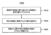
別の包括的な態様によると、ピクチャの領域に関して、属性がアクセスされる。ピクチャの領域は、特定の解像度において第1の整数個のピクセルと同一の広がりを持ち、第2の解像度において第2の整数個のピクセルと同一の広がりを持つ。属性は、領域に固有であり、特定の解像度と第2の解像度との組み合わせとして決定される組み合わせ解像度に固有である。属性は、領域および特定の解像度に固有の属性をもたらすように変換される。変換された属性は、特定の解像度の第1の整数個のピクセルに関連付けられる。 According to another generic aspect, attributes are accessed with respect to a region of a picture. The region of the picture has the same extent as the first integer number of pixels at a particular resolution and the same extent as the second integer number of pixels at the second resolution. The attribute is specific to the region, and is specific to the combination resolution determined as a combination of the specific resolution and the second resolution. The attributes are converted to provide attributes that are specific to the region and the particular resolution. The transformed attribute is associated with a first integer number of pixels of a particular resolution.
1または複数の実装の詳細が、添付の図面、および以下の説明で示される。1つの特定の方法で示されたとしても、実装がさまざまな方法で構成または具現化され得ることは明らかであるに違いない。例えば、実装は、方法として実行されるか、または、例えば、一組の動作を実行するように構成された装置、もしくは一組の動作を実行するための命令を記憶する装置などの装置として具現化されるか、または信号で具現化される可能性がある。その他の態様および特徴は、以下の詳細な説明を添付の図面および請求項とあわせて考察することから明らかとなるであろう。 The details of one or more implementations are set forth in the accompanying drawings and the description below. It should be apparent that even though shown in one particular way, implementations may be configured or embodied in various ways. For example, an implementation may be implemented as a method or embodied as a device, such as, for example, a device configured to perform a set of operations or a device that stores instructions for performing a set of operations. Or may be embodied as a signal. Other aspects and features will become apparent from the following detailed description considered in conjunction with the accompanying drawings and claims.
本出願で示される特徴の一部の事前確認として、少なくとも1つの実装が、対応するセル(複数のピクセル)にそれぞれが当てはまる(apply)1または複数の視差値を与える視差マップの使用を説明する。実際の視差値は、任意の標準的なディスプレイの最大の解像度よりもずっと大きく、非標準解像度と呼ばれる解像度に基づく。本出願において、用語「解像度」は、概して水平解像度を指すが、垂直解像度および/または水平解像度と垂直解像度との両方を指すためにも使用され、例えば、ディスプレイのピクセル数、またはディスプレイのピクセルのブロック数、またはディジタル画像の要素数で計測される。非標準解像度は、いくつかの標準的なディスプレイ解像度のうちの1つまたは複数に容易に変換される整数である。この特定の実装において、有効ディスプレイ解像度は、いくつかの標準的なディスプレイ解像度の最小公倍数である。有効ディスプレイ解像度に対する視差値は、整数フォーマットで表される。視差値は、大きな非ディスプレイ解像度(non−display resolution)に基づいている結果として、潜在的に大きい。さらに、整数表現は、視差値が標準的なディスプレイ解像度にダウンコンバートされるときにサブピクセルの精度をもたらす。加えて、セルのサイズおよび位置は、2つ以上の解像度の整数個のピクセルと同一の広がりを持つ。実際の整数は、異なる解像度において異なる。このサイズおよび位置、ならびにセル全体に対する単一の視差値の使用は、解像度が変更されるときにセルの視差値が同じままであることを可能にする。しかし、視差値は、異なる解像度においてはさまざまな数のピクセルに関連付けられる。 As a preconfirmation of some of the features presented in this application, at least one implementation describes the use of a disparity map that provides one or more disparity values each applicable to a corresponding cell (multiple pixels). . The actual disparity value is much larger than the maximum resolution of any standard display and is based on a resolution called non-standard resolution. In this application, the term “resolution” generally refers to horizontal resolution, but is also used to refer to vertical resolution and / or both horizontal and vertical resolution, eg, the number of pixels in a display, or the number of pixels in a display. It is measured by the number of blocks or the number of elements of a digital image. A non-standard resolution is an integer that is easily converted to one or more of several standard display resolutions. In this particular implementation, the effective display resolution is the least common multiple of some standard display resolutions. The disparity value for the effective display resolution is expressed in an integer format. The disparity value is potentially large as a result of being based on a large non-display resolution. Furthermore, the integer representation provides sub-pixel accuracy when the disparity value is downconverted to standard display resolution. In addition, the size and position of the cell is coextensive with an integer number of pixels of two or more resolutions. The actual integer will be different at different resolutions. This size and position, and the use of a single disparity value for the entire cell, allows the cell disparity value to remain the same when the resolution is changed. However, disparity values are associated with different numbers of pixels at different resolutions.
上記事前確認から離れて、図1は、ビデオ画像におけるデプスの概念を示す。図1は、センサー107を有する右カメラ105と、センサー112を有する左カメラ110とを示す。両方のカメラ105、110は、物体115の画像を撮影している。例示を目的として、物体115は物理的な十字であり、十字の右側に位置する任意の詳細116を有する(図2参照)。右カメラ105は、撮影角120を有し、左カメラ110は、撮影角125を有する。2つの撮影角120、125は、3Dステレオ領域(3D stereo area)130において重なる。
Apart from the prior confirmation, FIG. 1 shows the concept of depth in a video image. FIG. 1 shows a
物体115は、3Dステレオ領域130内にあるので、両方のカメラ105、110に見えており、したがって、デプスを有すると知覚され得る。物体115は、実際のデプス135を有する。実際のデプス135は、概して、物体115からカメラ105、110までの距離と呼ばれる。より詳細には、実際のデプス135は、物体115から、両方のカメラ105、110の入射瞳平面によって画定される平面であるステレオカメラベースライン(stereo camera baseline)140までの距離と呼ばれる可能性がある。カメラの入射瞳平面は、通常、ズームレンズの中にあり、したがって、通常、物理的にアクセスできない。
Since the
また、カメラ105、110は、焦点距離145を有するように示されている。焦点距離145は、射出瞳平面からセンサー107、112までの距離である。例示を目的として、ほとんどの場合、入射瞳平面および射出瞳平面がわずかに離れているとき、それらは一致するものとして示されている。加えて、カメラ105、110は、ベースライン長(baseline length)150を有するものとして示されている。ベースライン長150は、カメラ105、110の入射瞳の中心の間の距離であり、したがって、ステレオカメラベースライン140において計測される。
The
物体115は、カメラ105および110のそれぞれによって、センサー107および112のそれぞれの上の実像(real image)として撮像される。これらの実像は、センサー107上の詳細116の実像117と、センサー112上の詳細116の実像118とを含む。図1に示されるように、実像は、当技術分野で知られているように反転されている。
The
デプスは、視差と緊密に関連している。図2は、カメラ110から撮影された左画像205と、カメラ105から撮影された右画像210とを示す。両方の画像205、210は、詳細116を有する物体115の表現を含む。画像210は、詳細116の詳細画像217を含み、画像205は、詳細116の詳細画像218を含む。詳細116の一番右の点は、左画像205の詳細画像218のピクセル220で撮影される、右画像210の詳細画像217のピクセル225で撮影される。ピクセル220およびピクセル225の位置の間の水平の差が、視差230である。物体の画像217、218は、垂直方向に位置合わせされており、したがって、詳細116の画像は両方の画像205、210において垂直方向に同じ位置取りを有すると仮定される。視差230は、左画像205および右画像210がそれぞれ視聴者の左目および右目によって見られるとき、物体215までのデプスの知覚をもたらす。
Depth is closely related to parallax. FIG. 2 shows a
図3は、視差と知覚されるデプスとの間の関係を示す。3人の観察者305、307、309がそれぞれのスクリーン310、320、330上の物体の2眼式立体映像のペアを見ているところが示されている。
FIG. 3 shows the relationship between parallax and perceived depth. Shown are three
第1の観察者305は、正の視差を有する物体の左の像315および物体の右の像317を見る。正の視差は、物体の左の像315がスクリーン310上で物体の右の像317の左にあるという事実を反映する。正の視差は、知覚されるまたは仮想的な物体319がスクリーン310の平面の後ろにあるように見える結果をもたらす。
The
第2の観察者307は、視差がゼロである物体の左の像325および物体の右の像327を見る。視差がゼロであることは、物体の左の像325がスクリーン320上で物体の右の像327と同じ水平位置にあるという事実を反映する。視差がゼロであることは、知覚されるまたは仮想的な物体329がスクリーン320と同じデプスにあるように見える結果をもたらす。
The
第3の観察者309は、負の視差を有する物体の左の像335および物体の右の像337を見る。負の視差は、物体の左の像335がスクリーン330上で物体の右の像337の右にあるという事実を反映する。負の視差は、知覚されるまたは仮想的な物体339がスクリーン330の平面の前にあるように見える結果をもたらす。
The
ここで、視差およびデプスは、文脈によってそうでないことが示されるかまたは要求されない限り、実装において交換可能なように使用される可能性があることに留意されたい。式1を用いて、我々は、視差がシーンのデプスに反比例することを知る。
It should be noted here that disparity and depth may be used interchangeably in an implementation unless otherwise indicated or required by the context. Using

ここで、「D」はデプス(図1の135)を示し、「b」は2つのステレオ画像カメラの間のベースライン長(図1の150)であり、「f」は各カメラの焦点距離(図1の145)であり、「d」は2つの対応する特徴点に関する視差(図2の230)である。 Here, “D” indicates depth (135 in FIG. 1), “b” is the baseline length between two stereo image cameras (150 in FIG. 1), and “f” is the focal length of each camera. (145 in FIG. 1), and “d” is the parallax (230 in FIG. 2) regarding two corresponding feature points.
上記の式1は、同じ焦点距離を有する平行なカメラに対して有効である。より複雑な式がその他のシナリオに関して定義され得るが、ほとんどの場合、式1が近似として使用され得る。しかし、さらに、当業者に知られているように、以下の式2が、少なくとも、輻湊するカメラのさまざまな構成に対して有効である。
d∞は、無限遠の物体に関する視差の値である。d∞は、輻湊角および焦点距離に依存し、ピクセル数ではなく(例えば)メートルで表される。焦点距離は、図1および焦点距離145に関連して既に検討された。輻湊角は、図4に示されている。
d ∞ is a parallax value for an object at infinity. d ∞ is convergence angle and depends on the focal length is expressed by not the number of pixels (for example) meters. Focal length has already been discussed in connection with FIG. 1 and
図4は、図1の平行な構成ではなく輻湊する構成で配置されたカメラ105およびカメラ110を含む。角410は、輻湊するカメラ105、110の視線を示し、角410は、輻湊角と呼ばれる可能性がある。
FIG. 4 includes
視差マップが、ビデオ画像に関する視差情報を提供するために使用される。視差マップは、概して、関連するビデオ画像内のピクセルに対応する幾何学図形的配列を有する一組の視差値を指す。 A disparity map is used to provide disparity information about the video image. A disparity map generally refers to a set of disparity values having a geometrical arrangement corresponding to pixels in the associated video image.
概して、密な視差マップは、通常、関連するビデオ画像の解像度と同一である空間および時間解像度の視差マップを指す。時間解像度は、例えば、フレームレートを指し、例えば、50Hzまたは60Hzのどちらかである可能性がある。したがって、密な視差マップは、概して、ピクセル位置ごとに1つの視差サンプルを有する。通常、密な視差マップの幾何学図形的配列は、対応するビデオ画像の幾何学図形的配列、例えば、以下のピクセル数の水平および垂直サイズを有する長方形と同じである。
(i)1920×1080(もしくは1920×1200)、
(ii)1440×1080(もしくは1440×900)、
(iii)1280×720(もしくは1280×1024、1280×960、1280×900、1280×800)、
(iv)960×640(もしくは960×600、960×576、960×540)、
(v)2048×1536(もしくは2048×1152)、
(vi)4096×3072(もしくは4096×3112、4096×2304、4096×2400、4096×2160、4096×768)、または
(vii)8192×4302(もしくは8192×8192、8192×4096、7680×4320)。
In general, a dense disparity map typically refers to a disparity map of spatial and temporal resolution that is the same as the resolution of the associated video image. Temporal resolution refers to, for example, the frame rate and can be either 50 Hz or 60 Hz, for example. Thus, a dense disparity map generally has one disparity sample per pixel location. Typically, the dense parallax map geometry is the same as the corresponding video image geometry, eg, a rectangle with the following number of pixels in horizontal and vertical sizes.
(I) 1920 × 1080 (or 1920 × 1200),
(Ii) 1440 × 1080 (or 1440 × 900),
(Iii) 1280 × 720 (or 1280 × 1024, 1280 × 960, 1280 × 900, 1280 × 800),
(Iv) 960 × 640 (or 960 × 600, 960 × 576, 960 × 540),
(V) 2048 × 1536 (or 2048 × 1152),
(Vi) 4096 × 3072 (or 4096 × 3112, 4096 × 2304, 4096 × 2400, 4096 × 2160, 4096 × 768), or (vii) 8192 × 4302 (or 8192 × 8192, 8192 × 4096, 7680 × 4320) .
密な視差マップの解像度は、関連する画像の解像度とほぼ同じであるが、異なる可能性がある。1つの実装において、画像の境界の視差情報は、取得するのが難しい。したがって、その実装において、境界ピクセルにおける視差値は、視差マップに含められず、視差マップは、関連する画像よりも小さい。 The resolution of the dense parallax map is approximately the same as the resolution of the associated image, but can be different. In one implementation, the parallax information at the image boundaries is difficult to obtain. Thus, in that implementation, the disparity values at the boundary pixels are not included in the disparity map, and the disparity map is smaller than the associated image.
概して、ダウンサンプリングされた視差マップは、ネイティブのビデオ解像度よりも小さい(例えば、4分の1の)解像度の視差マップを指す。ダウンサンプリングされた視差マップは、例えば、ピクセルのブロックごとに1つの視差値を有する。ブロックは、どちらの方向についても必ずしも整数のピクセル数ではない。1つの実装において、ダウンサンプリングされた視差マップは、水平方向に2.5ピクセルおよび垂直方向に2.5ピクセルであるブロックに関する視差値を提供する。 In general, a downsampled disparity map refers to a disparity map with a resolution (eg, a quarter) smaller than the native video resolution. The downsampled disparity map has, for example, one disparity value for each block of pixels. A block is not necessarily an integer number of pixels in either direction. In one implementation, the downsampled disparity map provides disparity values for blocks that are 2.5 pixels horizontally and 2.5 pixels vertically.
概して、疎な視差マップは、密でない視差マップを指す。したがって、疎な視差マップは、ダウンサンプリングされた視差マップを含む。多くのアプリケーションにおいて、疎な視差マップは、対応するビデオ画像内で容易に追跡可能と見なされる画像の特徴点に対応する制限された数の(例えば、1000個の)ピクセルに対応する一組の視差を含む。選択される制限された数のピクセルは、概して、内容(content)自体に依存する。しばしば、画像には1または2百万ピクセル以上(1280×720または1920×1080)が存在する。概して、ピクセルのサブセットの選択は、特徴点を検出することができるトラッカーツールによって自動的または準自動的に行われる。トラッカーツールは、容易に入手可能である。特徴点は、例えば、その他の画像において容易に追従され得るピクチャ内のエッジまたはコーナーの点である可能性がある。概して、物体の高コントラストのエッジを表す特徴が、ピクセルのサブセットのために好ましい。 In general, a sparse disparity map refers to a disparity disparity map. Accordingly, the sparse disparity map includes a downsampled disparity map. In many applications, a sparse disparity map is a set of corresponding to a limited number (eg, 1000) of pixels corresponding to image feature points that are considered easily trackable within the corresponding video image. Includes parallax. The limited number of pixels selected generally depends on the content itself. Often there are 1 or 2 million pixels or more (1280 × 720 or 1920 × 1080) in an image. In general, the selection of a subset of pixels is done automatically or semi-automatically by a tracker tool that can detect feature points. Tracker tools are readily available. A feature point can be, for example, an edge or corner point in a picture that can be easily followed in other images. In general, features that represent the high contrast edges of an object are preferred for a subset of pixels.
視差マップ、またはより広く、視差情報は、さまざまな処理動作のために使用され得る。そのような動作は、例えば、コンシューマデバイス上の3Dエフェクトの調整、インテリジェントな字幕の配置、VFX、およびグラフィックスの挿入のための像の内挿(interpolation)(レンダリング)を含む。 The disparity map, or more broadly, disparity information can be used for various processing operations. Such operations include, for example, adjustment of 3D effects on consumer devices, intelligent subtitle placement, VFX, and image interpolation (rendering) for graphics insertion.
1つの特定の実装においては、グラフィックスが画像の背景に挿入される。この実装においては、3D表示が、スポーツキャスターとフットボール選手との間の2眼式立体ビデオインタビューを含み、それらの両方は前景にある。背景は、スタジアムの像を含む。この例において、視差マップは、対応する視差値が所定値よりも小さい(つまり、より近い)ときに、2眼式立体ビデオインタビューからのピクセルを選択するために使用される。対照的に、視差値が所定値よりも大きい(つまり、より遠い)場合、ピクセルはグラフィックから選択される。これは、例えば、ディレクターが、実際のスタジアムの背景の前ではなくグラフィック画像の前にインタビューの関係者を示すことを可能にする。その他の変更形態においては、背景が、選手の最も新しい得点を決めたプレーのリプレー中、例えば、競技場などの別の環境で置き換えられる。 In one particular implementation, graphics are inserted into the background of the image. In this implementation, the 3D display includes a binocular stereoscopic video interview between a sports caster and a football player, both of which are in the foreground. The background includes a stadium statue. In this example, the disparity map is used to select pixels from the binocular stereoscopic video interview when the corresponding disparity value is less than (ie, closer to) a predetermined value. In contrast, if the parallax value is greater (ie, farther) than the predetermined value, the pixel is selected from the graphic. This allows, for example, the director to show the interviewers in front of the graphic image rather than in front of the actual stadium background. In other variations, the background is replaced with another environment, such as a stadium, during replay of the play that scored the player's newest score.
1つの実装においては、3Dエフェクトが、ユーザのプリファレンスに基づいて和らげられる(減らされる)。3Dエフェクトを減らす(視差の絶対値を減らす)ために、新しい像が、視差およびビデオ画像を用いて内挿される。例えば、新しい像は、既存の左の像と右の像との間の位置に位置を定められ、左の像および右の像のうちの一方を置き換える。したがって、新しい2眼式立体映像のペアは、より小さなベースライン長を有し、削減された視差を有し、したがって、削減された3Dエフェクトを有する。 In one implementation, 3D effects are softened (reduced) based on user preferences. To reduce the 3D effect (decrease the absolute value of the parallax), a new image is interpolated using the parallax and the video image. For example, the new image is positioned at a position between the existing left and right images and replaces one of the left and right images. Thus, the new binocular stereo image pair has a smaller baseline length, reduced parallax, and thus reduced 3D effects.
別の実装においては、内挿ではなく外挿が、見かけのデプスを強調し、それによって3Dエフェクトを強めるために実行される。この実装においては、元の左の像および右の像のうちの一方に対する延長されたベースライン長を有する仮想カメラに対応する新しい像が、外挿される。 In another implementation, extrapolation rather than interpolation is performed to emphasize the apparent depth and thereby enhance the 3D effect. In this implementation, a new image corresponding to a virtual camera having an extended baseline length for one of the original left and right images is extrapolated.
別の例において、視差マップは、視聴者の不快感を和らげるかまたはなくすために、ビデオ画像内の字幕をインテリジェントに配置するために使用される。例えば、字幕は、概して、字幕が隠蔽しているあらゆる物体の前にある知覚されるデプスを有するべきである。しかし、知覚されるデプスは、概して、対象の領域と同程度であり、対象の領域内にある物体から前に離れ過ぎないデプスを有するべきである。 In another example, a parallax map is used to intelligently place subtitles in a video image to relieve or eliminate viewer discomfort. For example, subtitles should generally have a perceived depth in front of any object that the subtitles are hiding. However, the perceived depth should generally be comparable to the area of interest and have a depth that is not too far away from objects within the area of interest.
多くの3D処理動作に関して、ダウンサンプリングされた視差マップまたはその他の疎な視差マップよりも密な視差マップが好ましい。例えば、ユーザが制御可能な3Dエフェクトを可能にする(enable)ために視差マップが使用されるときは、概して、ピクセルごとの視差情報が好ましい。疎な視差マップ(例えば、ダウンサンプリングされた視差マップ)を使用することは合成された像の品質を劣化させる可能性があるので、ピクセルごとの視差情報は、概して、より良い結果が実現されることを可能にする。 For many 3D processing operations, a denser disparity map is preferred over a downsampled disparity map or other sparse disparity map. For example, per-pixel disparity information is generally preferred when disparity maps are used to enable user-controllable 3D effects. Since using a sparse disparity map (eg, a downsampled disparity map) can degrade the quality of the synthesized image, per-pixel disparity information generally provides better results. Make it possible.
視差値は、さまざまなフォーマットで表され得る。いくつかの実装は、記憶または送信のために以下のフォーマットを使用して視差値を表現する。
(i)符号付き整数:2の補数
・(a)負の視差値はスクリーンの前のデプスを示す。
・(b)ゼロは、スクリーン平面内の物体に関する視差値のために使用される。
(ii)1/8ピクセル単位
(iii)視差値を表す16ビット
・(a)典型的な視差の範囲は+80ピクセルと−150ピクセルとの間で変わる。これは、概して、1920または2048の解像度を有する40インチ(101.6センチメートル)ディスプレイに対して十分である。
・(b)1/8ピクセルの精度で、範囲は+640単位と−1200単位との間であり、これは、11ビット+符号のための1ビット=12ビットで表され得る。
・(c)(1920または2048ピクセル幅であるディスプレイの水平解像度の約4倍を有する)8kディスプレイで同じ3Dエフェクトを維持するために、我々は、通常、視差を符号化するための2つの追加のビット:12+2=14ビットを必要とする
・(d)これは将来使用するための2ビットを提供する
さらに、上記のフォーマットを使用するさまざまな実装は、密な視差マップも提供する。したがって、そのような実装のための密な視差マップを完成させるために、上記の16ビットのフォーマットが、対応するビデオ画像内のあらゆるピクセル位置に対して与えられる。
The disparity value can be expressed in various formats. Some implementations express disparity values using the following format for storage or transmission.
(I) Signed integer: 2's complement number (a) A negative parallax value indicates the depth before the screen.
(B) Zero is used for disparity values for objects in the screen plane.
(Ii) 1/8 pixel unit (iii) 16 bits representing a disparity value (a) A typical disparity range varies between +80 pixels and −150 pixels. This is generally sufficient for a 40 inch display having a resolution of 1920 or 2048.
(B) With an accuracy of 1/8 pixel, the range is between +640 units and -1200 units, which can be expressed as 11 bits + 1 bit for code = 12 bits.
(C) In order to maintain the same 3D effect on an 8k display (having about 4 times the horizontal resolution of a display that is 1920 or 2048 pixels wide), we typically add two additional to encode the disparity Bits: 12 + 2 = 14 bits required (d) This provides 2 bits for future use In addition, various implementations using the above format also provide a dense disparity map. Thus, to complete a dense disparity map for such an implementation, the above 16-bit format is provided for every pixel location in the corresponding video image.
視差と、関連するデプスの変化とは、シーンの異なる像の間の隠蔽をもたらす。図5は、視聴者の脳内で組み合わさって3Dシーン530を生じる左の像510および右の像520を示す。左の像510、右の像520、および3Dシーン530は、それぞれ、太い円柱532、楕円534、および細い円柱536を含む3つの物体を含む。しかし、図5に示されるように、3つの物体532、534、536のうちの2つは、像510、520および3Dシーン530のそれぞれで異なる相対位置にある。それらの2つの物体は、太い円柱532および細い円柱536である。楕円534は、像510、520、および3Dシーン530のそれぞれで同じ相対位置にある。
The parallax and associated depth changes result in concealment between different images of the scene. FIG. 5 shows a
異なる相対位置は、以下の簡潔な検討によって説明されるように隠蔽を生じる。左の像510は、隠蔽された領域545および548も見せる左画像540に示される。隠蔽された領域545および548は、左の像510でのみ可視であり、右の像520では不可視である。これは、(i)隠蔽された領域545に対応する右の像520内の領域が太い円柱532によって覆われており、(ii)隠蔽された領域548に対応する右の像520内の領域が細い円柱536によって覆われているためである。
The different relative positions result in concealment as explained by the following brief discussion. The
同様に、右の像520は、2つの隠蔽された領域555および558も見せる右画像550に示される。隠蔽された領域555、558は、右の像520でのみ可視であり、左の像510では不可視である。これは、(i)隠蔽された領域555に対応する左の像510内の領域が太い円柱532によって覆われており、(ii)隠蔽された領域558に対応する左の像510内の領域が細い円柱536によって覆われているためである。
Similarly, the
隠蔽が2眼式立体映像のペアに存在する可能性があるとすると、2眼式立体映像のペアに関する2つの視差マップを提供することが有用である。1つのそのような実装においては、左の視差マップが左のビデオ画像に対して与えられ、右の視差マップが右のビデオ画像に対して与えられる。知られているアルゴリズムが、標準的な視差ベクトルの方法を使用して視差値が決定され得ない各画像のピクセル位置に視差値を割当てるために使用される可能性がある。そのとき、隠蔽領域は、左の視差値と右の視差値とを比較することによって判定され得る。 Given that concealment may exist in a pair of binocular stereoscopic images, it is useful to provide two parallax maps for the pair of binocular stereoscopic images. In one such implementation, a left disparity map is provided for the left video image and a right disparity map is provided for the right video image. Known algorithms may be used to assign disparity values to pixel positions in each image for which disparity values cannot be determined using standard disparity vector methods. Then, the concealment region can be determined by comparing the left parallax value with the right parallax value.
左の視差値と右の視差値とを比較する例として、左目画像および対応する右目画像を考える。ピクセルLは、行Nにあり、左目画像において水平座標xLを有する。ピクセルLは、視差値dLを有すると判定される。ピクセルRは、対応する右目画像の行Nにあり、xL+dLに最も近い水平座標を有する。ピクセルRは、約「−dL」の視差値dRを有すると判定される。そのときは、視差が互いに対応するので、高い信頼度で、LまたはRに隠蔽は存在しない。つまり、ピクセルLおよびRは、両方とも、それらの判定された視差でおおむね互いを指す。 As an example of comparing the left parallax value with the right parallax value, consider a left eye image and a corresponding right eye image. Pixel L is in row N and has a horizontal coordinate x L in the left eye image. Pixel L is determined to have a disparity value d L. Pixel R is in row N of the corresponding right eye image and has a horizontal coordinate closest to x L + d L. Pixel R is determined to have a parallax value d R of about “−d L ”. At that time, since the parallaxes correspond to each other, there is no concealment in L or R with high reliability. That is, the pixels L and R both generally point to each other with their determined parallax.
しかし、dRが−dLとほぼ同じではない場合、隠蔽が存在する可能性がある。例えば、符号を考慮に入れた後、2つの視差値が実質的に異なる場合、概して、隠蔽が存在する高い信頼度が存在する。1つの実装においては、実質的な違いは、|dL−dR|>1によって示される。加えて、視差値のうちの一方(dRまたはdLのどちらか)が利用できない場合、概して、隠蔽が存在する高い信頼度が存在する。視差値は、例えば、視差値が決定され得ないために利用できない可能性がある。隠蔽は、概して、2つの画像のうちの一方に関する。例えば、より小さい大きさを有する視差に関連するピクセルによって示されるか、または利用できない視差値に対応するピクセルによって示されるシーンの一部は、概して、他方の画像において隠蔽されていると見なされる。 However, if d R is not substantially the same as -d L, there is a possibility that the concealed is present. For example, after taking into account the sign, if the two disparity values are substantially different, there is generally a high confidence that concealment exists. In one implementation, the substantial difference is indicated by | d L −d R |> 1. In addition, if one of the disparity values (either dR or dL) is not available, there is generally a high confidence that concealment exists. The parallax value may not be used because the parallax value cannot be determined, for example. Concealment generally relates to one of the two images. For example, a portion of the scene indicated by pixels associated with disparity having a smaller magnitude or indicated by pixels corresponding to disparity values that are not available is generally considered to be hidden in the other image.
視差値を表現するための1つのあり得る方法は、ビデオ画像の所与のピクセル位置に関する視差のピクセル数を表現するために整数を使用することである。視差値は、ビデオ画像の特定の水平解像度に対する視差のピクセル数を表す。したがって、視差値は、特定の水平解像度に応じて決まる。そのような実装は、有用であり、効果的である可能性がある。 One possible way to represent the disparity value is to use an integer to represent the number of pixels of disparity for a given pixel location in the video image. The parallax value represents the number of pixels of parallax for a specific horizontal resolution of the video image. Therefore, the parallax value is determined according to a specific horizontal resolution. Such an implementation can be useful and effective.
しかし、その他の実装は、視差値にサブピクセルの精度を必要とする。概して、そのような実装は、視差値を表現するために浮動小数点数を使用し、したがって、小数部が視差値に含められ得る。これらの実装のうちのいくつかは、所与の水平解像度に固有の視差値を提供する。これらの実装も、有用であり、効果的である可能性がある。 However, other implementations require subpixel accuracy in the disparity value. In general, such implementations use floating point numbers to represent disparity values, so fractions can be included in the disparity values. Some of these implementations provide disparity values that are specific to a given horizontal resolution. These implementations can also be useful and effective.
他の一部の実装は、視差値を百分率の値として表現する。したがって、視差をピクセル数として表現する代わりに、視差は、水平解像度の百分率として表現される。例えば、所与のピクセル位置の視差が10ピクセルであり、水平解像度が1920である場合、百分率の視差値は、(10/1920)*100である。そのような実装は、やはり、視差にサブピクセルの精度を与えることができる。百分率の値の表現は、通常、整数表現ではなく浮動小数点表現である。例えば、水平解像度1920を有するディスプレイの1ピクセルの視差は、1/1920であり、これは0.0005208または.05208%である。
Some other implementations express the parallax value as a percentage value. Therefore, instead of expressing the parallax as the number of pixels, the parallax is expressed as a percentage of the horizontal resolution. For example, if the parallax at a given pixel location is 10 pixels and the horizontal resolution is 1920, the percentage parallax value is (10/1920) * 100. Such an implementation can still give sub-pixel accuracy to the parallax. The representation of percentage values is usually a floating point representation rather than an integer representation. For example, the 1-pixel parallax for a display with
さらに、そのような百分率の視差値は、その他の水平解像度に直接適用(apply)され得る。例えば、(i)ビデオ画像が水平解像度1920を有し、(ii)ビデオ画像がユーザの家に送信され、(iii)ユーザのディスプレイ装置が水平解像度1440を有すると仮定する。このシナリオにおいては、通常、ユーザのディスプレイ装置(またはセットトップボックス、またはルータ、または何らかのその他のプロセッサーもしくは処理デバイス)が、ビデオ画像の水平解像度を1920から1440に変換し、さらに、視差値が水平解像度1440に対応するように視差値を変換する。変換は、例えば、百分率の視差値に水平解像度を掛けることによって実行され得る。例えば、所与のピクセル位置に関する百分率の視差が1/2%であり、水平解像度が1920である場合、絶対的な視差値は1/2*1920/100である。これらの実装のうちのいくつかは、ビデオ画像および視差マップの水平解像度に関係なく、視差値の送信および記憶に、百分率の視差値である単一の視差値を使用する。そのような実装も、有用であり、効果的である可能性がある。
Furthermore, such percentage disparity values can be directly applied to other horizontal resolutions. For example, assume that (i) the video image has a
上述のように、送信システムが、ビデオ画像の水平解像度とは異なる送信フォーマットの水平解像度を使用する可能性がある。加えて、受信システムが、ビデオ画像を表示するために異なる水平解像度を使用する可能性がある。したがって、1つの水平解像度から別の水平解像度への変換が、必要とされる可能性がある。そのような変換は、ビデオ画像の解像度を変更するだけではなく、視差値が調整されることも必要とする。概して、そのような変換は、絶対的な視差値に対して必要とされるが、百分率の視差値に対しては必要とされない。 As mentioned above, the transmission system may use a horizontal resolution of the transmission format that is different from the horizontal resolution of the video image. In addition, the receiving system may use different horizontal resolutions for displaying video images. Thus, conversion from one horizontal resolution to another may be required. Such a conversion requires not only changing the resolution of the video image, but also adjusting the parallax value. Generally, such a transformation is required for absolute disparity values, but not for percentage disparity values.
以下の例は、さまざまな実装の間のトレードオフの一部についてのさらなる詳細を示す。 The following examples provide further details about some of the trade-offs between various implementations.
・(i)1つの実装は、視差値を、所与のビデオ解像度に対して、ピクセルの1/8の正確性で、絶対値(ピクセル数)としてフォーマットする(例えば、物体が、1920水平ピクセルを有するビデオコンテンツで10ピクセルの視差を有する可能性がある)。 (I) One implementation formats the disparity value as an absolute value (number of pixels) with 1/8 pixel accuracy for a given video resolution (eg, object is 1920 horizontal pixels) May have 10 pixel parallax in video content with
・(ii)操作の簡潔さおよび容易さを含め、そのようなシステムの多くの利点が存在する。 (Ii) There are many advantages of such a system, including simplicity and ease of operation.
・(iii)1つのそのようなシステムにおいては、最大で255ピクセルの視差を提供するための整数部分に関する8ビットと、(1/8の正確性または精度を得るための)小数部分に関する3ビットとの11ビットが使用される。符号ビットも使用されるか、またはシステムが+/−127ピクセルの視差値を提供する可能性があることに留意されたい。 (Iii) In one such system, 8 bits for the integer part to provide a disparity of up to 255 pixels and 3 bits for the fractional part (to obtain 1/8 accuracy or precision) 11 bits are used. Note that the sign bit may also be used or the system may provide a +/- 127 pixel disparity value.
・(iv)ビデオ画像が送信中に再フォーマットされる必要がある場合、視差マップも再フォーマットされ、情報の損失につながる可能性がある。例えば、図6を参照すると、実装が、水平解像度1920を有するネイティブのフォーマット610と、水平解像度1280(または別の実装においては1440)を有するようにダウンサンプリングされている送信フォーマット620とを使用する。ビデオ画像と同様に、デプスまたは視差マップが、概して、デプスの詳細の損失につながるサブサンプリングの前に濾波される。濾波は、濾波およびサブサンプリング動作630で行われる。濾波およびサブサンプリング動作は、ビデオ画像および視差画像に適用される。
(Iv) If the video image needs to be reformatted during transmission, the disparity map may also be reformatted, leading to loss of information. For example, referring to FIG. 6, an implementation uses a
・(v)さらに、新しい視差値が変換され、概して損なわれる。例えば、視差マップの解像度を下げる(つまり、視差値の数を少なくする)ダウンサンプリングの後、視差値は、送信フォーマットの解像度に変換される。1920から1280になるとき、10ピクセルの視差値は6.6666になる。これは、例えば、小数部分が0.125(1/8)の倍数にしかなれないために、6.625への値の切り下げを引き起こす。 (V) Furthermore, new parallax values are transformed and are generally lost. For example, after downsampling that lowers the resolution of the parallax map (that is, reduces the number of parallax values), the parallax values are converted to the resolution of the transmission format. When going from 1920 to 1280, the 10-pixel disparity value becomes 6.6666. This causes the value to be rounded down to 6.625, for example, because the fractional part can only be a multiple of 0.125 (1/8).
・(vi)送信の後、ディスプレイが1920ピクセルの幅である場合、最終的な視差値は、6.625×1920/1280=9.9375になる。値9.9375は、元の値10と比較して、何らかの歪みを表す。値9.9375は、例えば、切り上げられるか、切り下げられるか、または最も近い整数に丸められるか、または最も近い1/8に丸められる可能性があり、おそらくは情報の損失を生じる。値が切り下げられるとした場合、損失は大きい。 (Vi) After transmission, if the display is 1920 pixels wide, the final disparity value is 6.625 × 1920/1280 = 9.9375. A value of 9.9375 represents some distortion compared to the original value of 10. The value 9.9375 can be rounded up, rounded down, rounded to the nearest integer, or rounded to the nearest 1/8, possibly resulting in a loss of information. If the value is rounded down, the loss is significant.
1つの解決策は、すべての水平解像度に共通であることができる百分率の視差を使用することである。上述のそのような実装は、利点および欠点を有する。百分率の視差値の使用は、送信前の変換動作が省略されることを可能にする。 One solution is to use a percentage parallax that can be common to all horizontal resolutions. Such an implementation as described above has advantages and disadvantages. The use of a percentage disparity value allows the conversion operation before transmission to be omitted.
別の解決策は、いずれか1つのよくある解像度に固有ではない整数値を使用することである。(ピクチャは、通常、垂直方向に修正されたと想定され、その他の処理を受けていることに留意されたい。したがって、通常、水平方向の変位の観点で視差について検討すれば十分である。)この解決策は、本出願においてはいくつかの標準的なTVの水平解像度(720、960、1280、1440、1920)の最小公倍数(smallest common multiple)(「SCM」)と呼ばれる11,520ピクセルの基準解像度(reference resolution)(または仮想解像度(virtual resolution))を定義することを提案する。SCMは、さまざまな参考文献において「最小公倍数(lowest common multiple)」または「最小公倍数(least common multiple)」とも呼ばれ、これらは両方ともLCMと略される可能性があることに留意されたい。 Another solution is to use integer values that are not specific to any one common resolution. (Note that a picture is usually assumed to have been modified in the vertical direction and has undergone other processing. Therefore, it is usually sufficient to consider parallax in terms of horizontal displacement.) The solution is a standard of 11,520 pixels, referred to in this application as the least common multiple (“SCM”) of several standard TV horizontal resolutions (720, 960, 1280, 1440, 1920). It is proposed to define a resolution (or virtual resolution). Note that SCM is also referred to as “lowest common multiple” or “least common multiple” in various references, both of which may be abbreviated as LCM.
このSCMの解決策の少なくとも1つの実装は、以下を含むいくつかの利点を有する(その他の実装がこれらの利点のすべてを有するとは限らない)。 At least one implementation of this SCM solution has several advantages, including the following (other implementations may not have all of these advantages):
・(i)視差値が整数であるので、視差値の判定および記憶が簡単であり、視差値は操作および処理が容易である。 (I) Since the parallax value is an integer, it is easy to determine and store the parallax value, and the parallax value is easy to manipulate and process.
・(ii)視差値が、もはや完全に絶対的ではなく、相対的な特徴を有し、したがって、ネイティブのビデオ解像度に依存しない。 (Ii) The disparity value is no longer completely absolute and has relative characteristics and is therefore independent of the native video resolution.
・(iii)小数部分が必要とされない。 (Iii) No decimal part is required.
・(iv)視差値が、相対的であり、ネイティブのビデオ解像度に依存しないので、百分率に似ている。しかし、視差値は整数であり、したがって、最小の視差値を示すために0.00868%のような複雑な数を符号化する明確な必要性がない。最小の視差値は1ピクセルであり、1/11,520は0.00868%である。 (Iv) Similar to percentage because the disparity value is relative and does not depend on the native video resolution. However, the disparity value is an integer, so there is no clear need to encode a complex number such as 0.00868% to indicate the minimum disparity value. The minimum parallax value is 1 pixel, and 1 / 11,520 is 0.00868%.
・(v)視差値が11,520に依拠するので、転送中に視差値をコード変換する明確な必要性が存在しない。 (V) Since the disparity value depends on 11,520, there is no clear need to transcode the disparity value during transfer.
・(vi)SCMに基づく視差値が例えばセットトップボックス(STB)に到着するとき、STBが、例えば、
○(a)解像度1920に関して視差/6
○(b)解像度1440に関して視差/8
○(c)解像度1280に関して視差/9
○(d)解像度960に関して視差/12
などの非常に単純な演算(operation)を実行することによって所与のビデオ解像度に対する真の絶対的な視差を計算する。
(Vi) When a disparity value based on SCM arrives at a set top box (STB), for example, the STB
○ (a) Parallax for
○ (b) Parallax / 8 with respect to
○ (c) Parallax / 9 for
○ (d) Parallax / 12 with respect to
Calculate the true absolute disparity for a given video resolution by performing a very simple operation such as
・(vii)どのチャネルが使用されるかに関係なく、コード変換がない限り、視差情報が転送中に劣化しない。 (Vii) Regardless of which channel is used, as long as there is no code conversion, disparity information does not deteriorate during transfer.
・(viii)2k、4k、8kのような比較的新しいコンシューマ解像度に関しても、演算は実施するのが簡単であり、それはSTBの処理ユニットで容易に実施可能である。概して、2kは水平ピクセル解像度2048を有する画像を指し、概して、4kは4096を指し、概して、8kは8192を指すことに留意されたい。演算は、例えば、
○(a)解像度2048に関して視差×8/45
○(b)解像度4096に関して視差×16/45
○(c)解像度8192に関して視差×32/45
である。
(Viii) For relatively new consumer resolutions such as 2k, 4k, 8k, the operation is simple to implement, which can be easily implemented in the STB processing unit. Note that generally 2k refers to an image having a
○ (a) Parallax x 8/45 with respect to
○ (b) Parallax x 16/45 for resolution 4096
○ (c) Parallax x 32/45 with respect to resolution 8192
It is.
実際には、1または複数のSCMの実装は、(1)対応するビデオコンテンツの既存の水平解像度に対する視差値を判定し、(2)単純な乗算および/または除算によってそれらの視差値を11,520のスケールに変換してSCM視差値(SCM disparity value)を生成し、(3)コード変換なしにSCM視差値を記憶し、送信し、(4)単純な乗算および/または除算を用いて、受信されたSCM視差値を出力ディスプレイの解像度に変換する。コード変換が存在しないので、この解決策は、概して、コード変換による情報の損失(例えば、丸めの損失)を被らない。視差マップの解像度は上記プロセスによって変更されないことに留意されたい。むしろ、(既存の解像度に関する)既存の視差値が、実際の解像度とは異なる基準解像度(または仮想解像度)に基づくか、または基準解像度(または仮想解像度)を反映するようにスケール化される。 In practice, one or more SCM implementations (1) determine the disparity values for the existing horizontal resolution of the corresponding video content, and (2) reduce the disparity values to 11, 11 by simple multiplication and / or division. Convert to 520 scale to generate SCM disparity value, (3) store and transmit SCM disparity value without transcoding, and (4) use simple multiplication and / or division, The received SCM parallax value is converted to the resolution of the output display. Since no code conversion exists, this solution generally does not suffer from loss of information (eg, rounding loss) due to code conversion. Note that the resolution of the disparity map is not changed by the above process. Rather, the existing disparity value (with respect to the existing resolution) is based on a reference resolution (or virtual resolution) that is different from the actual resolution or scaled to reflect the reference resolution (or virtual resolution).
さまざまな実装は、上述の演算の逆である単純な数学的演算を実行することによって視差値を生成する。例えば、SCM視差値を生成するために、受信された絶対的な視差値に、以下のように、1つまたは2つの整数が乗算および/または除算される。
○(i)1920視差*6=SCM視差
○(ii)1440視差*8=SCM視差
○(iii)1280視差*9=SCM視差
○(iv)960視差*12=SCM視差
○(v)2048視差*45/8=SCM視差
○(vi)4096視差*45/16=SCM視差
○(vii)8192視差*45/32=SCM視差
Various implementations generate disparity values by performing simple mathematical operations that are the inverse of the operations described above. For example, to generate an SCM disparity value, the received absolute disparity value is multiplied and / or divided by one or two integers as follows.
○ (i) 1920 parallax * 6 = SCM parallax ○ (ii) 1440 parallax * 8 = SCM parallax ○ (iii) 1280 parallax * 9 = SCM parallax ○ (iv) 960 parallax * 12 = SCM parallax ○ (v) 2048 parallax * 45/8 = SCM parallax ○ (vi) 4096 parallax * 45/16 = SCM parallax ○ (vii) 8192 parallax * 45/32 = SCM parallax
図7は、さまざまな異なる水平解像度に関する最小公倍数を決定するプロセスのさらなる詳細を示す。列710は、異なる水平解像度を列挙する。列720は、水平解像度の最小の因数を列挙する。例えば、960は、26*3*5と因数分解され、ここで、26は2の6乗である。したがって、960=64*3*5である。水平解像度1280に関して、30は1に等しいことも留意される。
FIG. 7 shows further details of the process of determining the least common multiple for a variety of different horizontal resolutions.
最初の4つの解像度960、1280、1440、および1920の最小公倍数は、28*32*5であり、これは11,520である。解像度11,520は、2の適切な累乗を乗算し、次に、2k、4k、および8kに存在しない因数32および5で除算することによって2k、4k、および8kの解像度で使用される。2の累乗の乗算は、さまざまな実装において、実際の乗算の演算ではなくビット単位の左シフト演算を用いて実行されることに留意されたい。図7は、11,520と列610に示されたさまざまな解像度との間の変換を行うための変換式を与える列730を含む。
The least common multiple of the first four
列630の変換式は、複数のよくあるディスプレイサイズ(例えば、インチまたはセンチメートルで計測されるディスプレイの物理的なサイズを指すディスプレイサイズ)によってサポートされる解像度に基づいて視差値をスケール化するために使用され得る。図6の例においては、例えば、水平解像度1920に基づく入力視差値が、視差値を水平解像度11,520に基づく新しい視差値に変換するために、因数6によってスケール化される。新しい視差値は、水平解像度960、1280、および1440が解像度11,520によって考慮され、解像度11,520を決定する際に使用されるので、それらにも基づく。
The transformation formula in
代替的な実装は、単純に、視差の解像度11,520*25=368,640を使用する。この代替的な実装においては、368,640を元の解像度に変換して戻すために乗算が必要とされない。 An alternative implementation simply uses a parallax resolution of 11,520 * 2 5 = 368,640. In this alternative implementation, multiplication is not required to convert 368,640 back to the original resolution.
値11,520が、さまざまな実装のために使用される。しかし、その他の実装においてはその他の値が使用される。1つの実装においては、値11,520が2倍にされて23,040になる。第2の実装においては、値368,640が2倍にされて737,280になる。 The values 11,520 are used for various implementations. However, other values are used in other implementations. In one implementation, the values 11,520 are doubled to 23,040. In the second implementation, the values 368 and 640 are doubled to 737 and 280.
代替的に、水平解像度の異なる組が、さまざまな実装で使用され、異なるSCMをもたらす。例えば、別の実装においては、出力解像度1920および1440だけが対象であり、したがって、実装はSCM5,760を使用する。そのとき、SCM視差値を生成するために、解像度1920からの視差値は、因数3を乗算され、解像度1440からの視差値は、因数4を乗算される。
Alternatively, different sets of horizontal resolution are used in various implementations, resulting in different SCMs. For example, in another implementation,
さまざまな実装はSCMの実装ではないことは明らかであるに違いない。例えば、値11,520でさえも、列710に列挙された7つすべての解像度のSCMではない。正しくは、値368,640がSCMである。それでもなお、本出願に記載の実装は、概して、たとえ視差値が水平解像度のすべての最小公倍数ではないとしてもSCMの実装と呼ばれる。
It should be clear that the various implementations are not SCM implementations. For example, even the value 11,520 is not an SCM of all seven resolutions listed in
SCMの実装はサブピクセルの精度を提供することに留意されたい。例えば、解像度1920に関して、視差値は、解像度11,520への/からの変換を行うために因数6を使用し、これは1/6ピクセルの精度を提供する。より詳細には、11,520に基づく視差値が83である場合、1920に基づく視差値は13と5/6である。これは、明らかに1/6ピクセルの精度を提供する。これは、品質と、将来のニーズのための余裕との点でさまざまな利点をもたらす。例えば、解像度1920が解像度2kによって置き換えられる場合、11,520に基づく視差値は、それでも、8/45ピクセルの精度のサブピクセルの精度を提供し、これは、1/6(7.5/45)ピクセルよりも若干低い精度であるが、1/5(9/45)ピクセルよりはまだ高い精度である。
Note that the SCM implementation provides sub-pixel accuracy. For example, for
SCM解像度(SCM resolution)11,520を使用する少なくとも1つの実装は、2バイト(16ビット)フォーマットで動作する。多くの場合、典型的な視差の範囲は、1920×1080のディスプレイ(解像度)において+80ピクセルと−150ピクセルとの間で変わる。それらの数に6を掛けることは、基準解像度11,520において+480から−900までの範囲をもたらす。1380のこの範囲は、11ビット(211=2048)によって表され得る。代替的な実装は、視差の絶対値を表すための10ビット(視差の最大の絶対値は900である)と、符号を表すための追加のビットとを使用する。 At least one implementation that uses SCM resolution 11,520 operates in a 2 byte (16 bit) format. In many cases, the typical parallax range varies between +80 pixels and −150 pixels in a 1920 × 1080 display (resolution). Multiplying those numbers by 6 results in a range from +480 to -900 at a reference resolution of 11,520. This range of 1380 may be represented by 11 bits (2 11 = 2048). An alternative implementation uses 10 bits to represent the absolute value of the parallax (the maximum absolute value of the parallax is 900) and an additional bit to represent the sign.
さらに別の実装は、視差の符号が暗黙的であると見なすことによって1ビットを節約する。例えば、左の像のピクセルの視差が、視差の符号とともに符号化される。しかし、対応する右の像の対応するピクセルの視差は、反対の符号を有すると見なされる。 Yet another implementation saves one bit by considering the disparity code to be implicit. For example, the parallax of the pixel in the left image is encoded together with the parallax code. However, the parallax of the corresponding pixel in the corresponding right image is considered to have the opposite sign.
別の実装は、像(左の像と右の像との両方)ごとに1つの密な視差マップを提供し、それにより、隠蔽によって引き起こされる問題を減らすことができるように、密な視差マップが対応する像を示すためのビットを割当てる。別の実装は、画像(左の画像かまたは右の画像かのどちらか)と対応する密な視差マップとの間の暗黙的な関連付けを提供し、したがって、この情報に1ビットを充てる必要がない。これらの実装の変更形態は、その他の種類のマップまたは画像を導入するために1または複数の追加のビットを使用する。1つのそのような実装は、マップが(i)左画像の視差マップであるか、(ii)右画像の視差マップであるか、(iii)隠蔽マップ(occlusion map)であるか、または(iv)透過マップ(transparency map)であるかを示すために2ビットを使用する。1つの実装は、16ビットフォーマットを有し、−900から+480までの範囲を示すための11ビットを使用し、マップの種類を示すために2ビットを使用し、未使用の3ビットを有する。 Another implementation provides a dense disparity map for each image (both left and right images), thereby reducing the problems caused by concealment. Assign bits to indicate the corresponding image. Another implementation provides an implicit association between the image (either the left image or the right image) and the corresponding dense disparity map, so this information needs to be devoted to 1 bit. Absent. These implementation variations use one or more additional bits to introduce other types of maps or images. One such implementation is that the map is (i) a parallax map of the left image, (ii) a parallax map of the right image, (iii) an occlusion map, or (iv) ) 2 bits are used to indicate whether it is a transparency map. One implementation has a 16-bit format, uses 11 bits to indicate a range from -900 to +480, uses 2 bits to indicate the map type, and has 3 unused bits.
図8は、1または複数の実装の動作を示すブロック/フロー図を与える。図8は、異なる実装の間のトレードオフの一部も示す。 FIG. 8 provides a block / flow diagram illustrating the operation of one or more implementations. FIG. 8 also shows some of the trade-offs between different implementations.
図8は、ビデオを処理する処理チェーン810を含む。ビデオ画像811は、水平解像度1920を有する。しかし、処理チェーン810の送信フォーマットは、水平解像度1280を有する。したがって、ビデオ画像811は、水平解像度1280を有するビデオ画像813を生成するために動作812において濾波され、ダウンサンプリングされる。濾波およびダウンサンプリングは、処理チェーン810において一緒に実行される。しかし、その他の実装は、濾波およびダウンサンプリングを別々に実行する。濾波は、例えば、ビデオ画像811がダウンサンプリングされるときに折り返しひずみを防止する目的でビデオ画像811を低域通過濾波するために使用される。ビデオ画像813は、送信および/または記憶動作814で搬送される。
FIG. 8 includes a
チェーン810の受信側は、ビデオ画像813と同じであるか、同様であるか、または異なる可能性がある受信されたビデオ画像815にアクセスする。例えば、1つの実装において、ビデオ画像815は、ビデオ画像813の記憶されたバージョンである。加えて、別の実装においては、ビデオ画像815は、情報源符号化および復号動作(図示せず)の後のビデオ画像813の再構成されたバージョンを表す。さらに、別の実装においては、ビデオ画像815は、(誤り訂正を含む)チャネルの符号化および復号動作(図示せず)の後のビデオ画像813の誤り訂正されたバージョンを表す。ビデオ画像815は、元のビデオ画像811におけるように水平解像度1920を有するビデオ画像817を生成するために、アップサンプリング動作816で処理される。
The receiving side of
図8は、チェーン810で処理されるビデオ画像に対応する視差画像を処理する処理チェーン820も含む。視差画像821は、水平解像度1920を有し、解像度11,520に基づく整数値の視差値を含む。概して、視差画像は、例えば、密な視差マップ、ダウンサンプリングされた(疎な)視差マップ、または別の疎な視差マップなどの視差情報の任意の集積を指すことに留意されたい。さらに、視差マップは、例えば、ピクチャ、フレーム、フィールド、スライス、マクロブロック、パーティション、または視差情報の何らかのその他の集まりに対応する可能性がある。
FIG. 8 also includes a
しかし、処理チェーン820の送信フォーマットは、水平解像度1280を有する。したがって、視差画像821は、水平解像度1280を有する視差画像823を生成するために動作822において濾波され、ダウンサンプリングされる。濾波およびダウンサンプリングは、処理チェーン820において一緒に実行される。しかし、その他の実装は、濾波およびダウンサンプリングを別々に実行する。濾波は、例えば、視差画像821がダウンサンプリングされるときに折り返しひずみを防止する目的で視差画像821の視差値を低域通過濾波するために使用される。
However, the transmission format of the
視差画像823の視差値は、整数値である。これは、さまざまな手段で実現され得る。1つの実装において、濾波およびダウンサンプリング動作の結果は、最も近い整数に丸められる。別の実装においては、すべての小数部分が単純に切り捨てられる。さらに別の実装は、視差画像823の視差値に浮動小数点表現を使用する。視差値は、濾波およびダウンサンプリングが視差画像823の解像度1280を生成した後でさえも、引き続き解像度11,520に基づくことに留意されたい。
The parallax value of the
視差画像823は、送信および/または記憶動作824で搬送される。チェーン820の受信側は、受信された視差画像825にアクセスする。視差画像825は、視差画像823と同じであるか、同様であるか、または異なる可能性がある。例えば、1つの実装において、視差画像825は、視差画像823の記憶されたバージョンである。さらに、別の実装においては、視差画像825は、情報源符号化および復号動作(図示せず)の後の視差画像823の再構成されたバージョンを表す。さらに、別の実装においては、視差画像825は、(誤り訂正を含む)チャネルの符号化および復号動作(図示せず)の後の視差画像823の誤り訂正されたバージョンを表す。しかし、視差画像825の視差値は、例えば、必要に応じて丸めを使用することによって整数のままである。
The
視差画像825は、元の視差画像821におけるように水平解像度1920を有する視差画像827を生成するために、アップサンプリング動作826で処理される。動作826は、例えば、丸めまたは切り捨てを使用して、視差画像827の整数値を生成する。
The
視差画像827の視差値は、変換動作828で、解像度11,520に基づく状態から、解像度1920に基づく状態に変換される。変換動作828は、上で説明されたように、それぞれの視差値を6で割る。変換動作828は、視差画像829を生成する。視差画像829の視差値は、サブピクセルの精度を保つために浮動小数点数として表される。
The parallax value of the
処理チェーン820が大きな利点を含むことは明らかであるに違いない。第1に、視差値は、最終的な視差画像829がもたらされるまで、チェーン820全体を通じて整数である。第2に、実際の視差値は、送信フォーマットの水平解像度がネイティブの視差マップ821の水平解像度と異なるという事実にもかかわらず、コード変換されない。したがって、視差値は、さまざまな異なる水平解像度に適用可能である。
It should be clear that the
そして、受信システムが、視差画像829を使用してビデオ画像817を処理する。処理は、既に説明されたように、3Dエフェクトの調整、字幕の配置、グラフィックスの挿入、またはVFXの実行を含み得る。
The receiving system then processes the
図8は、比較を目的として、処理チェーン830も示す。処理チェーン830は、チェーン810で処理されるビデオ画像に対応する視差画像をやはり処理する。処理チェーン830は、処理チェーン820の代わりである。以下で説明されるように、チェーン830全体は、図8を簡潔にするために示されていないことは明らかであるに違いない。
FIG. 8 also shows a
視差画像831は、水平解像度1920を有し、浮動小数点表現を有する百分率に基づく視差値を含む。しかし、処理チェーン830の送信フォーマットは、水平解像度1280を有する。したがって、視差画像831は、水平解像度1280を有する視差画像833を生成するために動作832において濾波され、ダウンサンプリングされる。動作832は、例えば、濾波およびダウンサンプリング動作812または822と類似している可能性がある。視差画像833の百分率に基づく視差値は、引き続き浮動小数点フォーマットで表される。
The
処理チェーン830の残り(図示せず)は、処理チェーン820の残りと同じである。視差画像833は、送信および/または記憶動作で搬送される。チェーン830の受信側は、受信された視差画像にアクセスする。受信された視差画像が、水平解像度1920にアップサンプリングされ、次に、視差値が、百分率に基づく状態から解像度1920に基づく状態に変換される。変換動作は、上で説明されたように、百分率掛ける1920の操作である。しかし、処理チェーン820とは対照的に、処理チェーン830の視差画像の視差値は、常に浮動小数点フォーマットで表される。
The rest of the processing chain 830 (not shown) is the same as the rest of the
図8は、比較を目的として、処理チェーン840も示す。処理チェーン840は、チェーン810で処理されるビデオ画像に対応する視差画像をやはり処理する。処理チェーン840は、処理チェーン820の代わりである。以下で説明されるように、チェーン840全体は、図8を簡潔にするために示されていないことは明らかであるに違いない。
FIG. 8 also shows a
視差画像841は、水平解像度1920を有し、解像度1920に基づき、浮動小数点表現を有する視差値を含む。しかし、処理チェーン840の送信フォーマットは、水平解像度1280を有する。したがって、視差画像841は、水平解像度1280を有する視差画像843を生成するために動作842において濾波され、ダウンサンプリングされる。動作842は、例えば、濾波およびダウンサンプリング動作812、822、または823と類似している可能性がある。視差画像843の視差値は、引き続き浮動小数点フォーマットで表される。
The parallax image 841 has a
次に、視差画像843の視差値は、視差画像860を生成するために、変換動作850で変換される。変換動作850は、視差値を、水平解像度1920に基づく状態から水平解像度1280に基づく状態に変換する。視差画像860の視差値は、引き続き浮動小数点フォーマットで表される。
Next, the parallax value of the
処理チェーン840の残り(図示せず)は、処理チェーン820の残りと同じである。視差画像860は、送信および/または記憶動作で搬送される。チェーン840の受信側は、受信された視差画像にアクセスする。受信された視差画像が、水平解像度1920にアップサンプリングされ、次に、視差値が、解像度1280に基づく状態から解像度1920に基づく状態に変換される。変換動作は、視差値に1920/1280を乗算することをともなう。処理チェーン830と同様に、処理チェーン820とは対照的に、処理チェーン840の視差画像の視差値は、常に浮動小数点フォーマットで表される。
The rest of the processing chain 840 (not shown) is the same as the rest of the
処理チェーン840の別の実装においては、変換動作850が実行されない。したがって、視差画像843の視差値は、水平解像度1920に基づく視差値のままである。しかし、視差画像843の水平解像度は、1280のままである。したがって、この実装は、送信の前の変換を避け、おそらくは、受信または取得後の再変換を避ける。変換および再変換を避けることは、少なくとも一部の実装において、丸め誤差も避ける。この実装は、本出願のすべてのその他の実装と同様に、利点を有し、有用である可能性がある。しかし、視差値は、実装全体を通じて浮動小数点数で表される。
In another implementation of the
我々は、例えば、解像度11,520が使用されるSCMの実装に再び言及する。幅11,520は、既に説明されたように、一揃いの所定の画像解像度(例えば、960、1280、1440、および1920)の幅(水平軸)の最小公倍数と呼ばれる。11,520は、1280、1440、および1920の最小公倍数でもあることに留意されたい。 We refer again to an SCM implementation, for example, where a resolution of 11,520 is used. The widths 11,520 are referred to as the least common multiple of the width (horizontal axis) of a set of predetermined image resolutions (eg, 960, 1280, 1440, and 1920), as already described. Note that 11,520 is also the least common multiple of 1280, 1440, and 1920.
SCMを用いる水平視差の1つの計数は、「視差単位(disparity unit)」(DU)、または「水平単位(horizontal unit)」(HU)、または「水平視差単位(horizontal disparity unit)」(HDU)と呼ばれる可能性がある。DUによって視差を表すことは、選択された画像の幅の最小公倍数に関連して視差を効果的に表す。DUによって視差を表すことは、利点を有する。DUによって視差を表す1つのそのような利点は、選択された解像度のうちの1つのステレオ画像のペア内の物体に関して計算された視差が、選択された解像度のうちの異なる1つにスケール化された同じステレオ画像のペアのバージョン内の同じ物体に関して実質的に同じであることである。 One count of horizontal parallax using SCM is “disparity unit” (DU), or “horizontal unit” (HU), or “horizontal disparity unit” (HDU). May be called. Representing parallax by DU effectively represents parallax in relation to the least common multiple of the width of the selected image. Representing parallax by DU has advantages. One such advantage of representing disparity by DU is that the disparity calculated for objects in one stereo image pair of the selected resolution is scaled to a different one of the selected resolutions. It is substantially the same for the same object in a version of the same stereo image pair.
例えば、図9を参照すると、同じ領域を表すが、3つの異なる解像度の画像のピクセルの3つの行910、920、および930が示されている。加えて、SCM解像度11,520からの視差単位を示す第4の行940が存在する。
For example, referring to FIG. 9, three
一番上の行910は、1280ピクセル幅であるピクチャからのピクセルの領域を含む。一番上の行910は、示されるように8ピクセルを含む。実際、一番上の行910は、通常、アスペクト比1:1を有するピクセルに対応する画像アスペクト比16:9を有する解像度1280×720である。したがって、一番上の行910のピクセルは、正方形として示される。
The
第2の行920は、行910と同じピクチャからのピクセルの領域を含む。しかし、行920は、通常、同じ画像アスペクト比16:9を有するが、画素アスペクト比が4:3である解像度1440×1080を有する画像全体をもたらすようにピクチャが1440ピクセル幅になるようにリサイズされた後のピクチャから抜き出される。したがって、行920は、単純に行910のように8ピクセルを含むのではなく、示されるように9ピクセルを含む。
第3の行930は、行910および行920と同じピクチャからのピクセルの領域を含む。しかし、行930は、ピクチャが全体の画像解像度1920×1080の1920ピクセル幅になるようにリサイズされた後のピクチャから抜き出される。ピクチャは、検討されるその他の解像度と同様にアスペクト比16:9を有するが、行910と同じように画素アスペクト比1:1(正方形のピクセル)を有する。したがって、行930は、単純に行910のように8ピクセルを含むか、行920のように9ピクセルを含むのではなく、示されるように12ピクセルを含む。行910、行920、および行930は、すべて、ピクチャの対応する領域を表示し、同じコンテンツを含むことは明らかであるに違いない。
我々は、これらの4つの異なる解像度における視差の違いを示すための一例を与える。1つの実装において、物体は、丁度、ステレオ画像のペアのうちの一方の画像の1280ピクセル幅のバージョンの一番上の行910の一番左のピクセル912に現れ、丁度、ステレオ画像のペアのうちの対応する他方の目の画像の第5のピクセル914に現れる。視差は、一番上の行910の半分ほど、または(ピクセルで表すと)(5−1と計算される)丁度4である。
We give an example to show the difference in parallax at these four different resolutions. In one implementation, the object appears in the
しかし、第3の行930の再スケール化(rescale)された画像で計測されるとき、物体は、ステレオ画像のペアのうちの一方の画像の一番左のピクセル932に現れ、丁度、ステレオ画像のペアのうちの対応する他方の目の画像の第7のピクセル934に現れる。したがって、第3の行930の半分ほどである視差は、6ピクセルある。
However, when measured with the rescaled image in the
さらに、第2の行920の再スケール化された画像で計測されるとき、物体は、ステレオ画像のペアのうちの一方の画像の一番左のピクセル922に現れる。物体は、ステレオ画像のペアのうちの対応する他方の目の画像の第5のピクセル924の右半分にも現れる。したがって、第2の行920の半分ほどである視差は、4と1/2ピクセルある。
Further, when measured with the rescaled image in the
したがって、視差は、行910、920、および930の解像度のそれぞれで異なる。視差は、4ピクセルから、4と1/2ピクセルまで、6ピクセルまで変わる。
Thus, the parallax is different for each of the resolutions of
しかし、視差がDUで表されるとき、この同じ物体は、3つの解像度すべてにおいて36DUの視差を有する。これは、第4の行940を調べることによって理解され得る。第4の行940の再スケール化された画像で計測されるとき、物体は、ステレオ画像のペアのうちの一方の画像の一番左のDU942に現れ、丁度、ステレオ画像のペアのうちの対応する他方の目の画像の第37のDU944に現れる。したがって、第4の行940の半分ほどである視差は、36DUある。視差を計測するためにピクセルではなくDUを使用することにより、ピクチャが、異なる選択された解像度の間でスケール化されるとき、この物体の視差は、再計測、再計算、またはスケール化される必要がない。
However, when the parallax is expressed in DU, this same object has a 36 DU parallax in all three resolutions. This can be understood by examining the
既に説明されたように、密な視差マップは、通常、(ステレオ画像のペアと呼ばれる)2眼式立体映像のペアのうちの一方の画像の各ピクセルの内容に関連する視差値を含む。視差値は、ステレオ画像のペアの他方の画像に関連する。したがって、密な視差マップは、通常、対応する画像がピクセルを有するのと同じ数の視差のエントリを含む。 As already explained, a dense disparity map typically includes disparity values associated with the contents of each pixel of one image of a pair of binocular stereoscopic images (called a stereo image pair). The disparity value is related to the other image of the stereo image pair. Thus, a dense disparity map typically includes the same number of disparity entries as the corresponding image has pixels.
高解像度(例えば、1920ピクセル幅)の画像に関する第1の密な視差マップから、より低い解像度の画像に関する第2の密な視差マップが、第2の密な視差マップの値に空間的に重なる第1の密な視差マップの値の加重平均(またはその他の関数)によって計算され得る。 From the first dense parallax map for the high resolution (eg, 1920 pixel wide) image, the second dense parallax map for the lower resolution image spatially overlaps the value of the second dense parallax map. It can be calculated by a weighted average (or other function) of the values of the first dense disparity map.
1つの実装において、視差のダウンスケール化(downscaling)関数は、加重平均である。この実装において、第2の密な視差マップの値は、積の和に等しい。合計される積は、第1のマップの各ピクセルに対応する視差を、視差値が計算されている第2のマップのピクセルのそれとのその対応するピクセルの交差の(第2のマップのピクセルに正規化された)面積と乗算した積である。 In one implementation, the parallax downscaling function is a weighted average. In this implementation, the value of the second dense parallax map is equal to the sum of products. The summed product gives the disparity corresponding to each pixel of the first map to the intersection of that corresponding pixel with that of the second map pixel whose disparity value is being calculated (to the pixel of the second map). The product of (normalized) area multiplied.
例えば、図10に関連して、2つのピクセルグリッドの重なりの部分が示されている。第1のピクセルグリッドは、マップ1と呼ばれ、比較的高い解像度のピクチャのピクセルグリッドである。第2のピクセルグリッドは、マップ2と呼ばれ、比較的低い解像度のピクチャのピクセルグリッドである。マップ1およびマップ2は図10にそれらの全体が示されていないことは明らかであるに違いない。図10は、マップ1およびマップ2の重なりの部分を示す。
For example, with reference to FIG. 10, an overlapping portion of two pixel grids is shown. The first pixel grid is called
図10のグリッドは、視差マップにやはり対応する。第1の視差マップは、マップ1の各ピクセル位置に関する視差値を与え、マップ1視差マップと呼ばれることがある。第2の視差マップは、マップ2の各ピクセル位置に関する視差値を与え、マップ2視差マップと呼ばれることがある。マップ1視差マップは、比較的高い解像度のピクチャの密な視差マップであり、高解像度視差マップと呼ばれることがある。マップ2視差マップは、比較的低い解像度のピクチャの密な視差マップであり、低解像度視差マップと呼ばれることがある。以降のさまざまな実装において、マップ2視差マップは、マップ1視差マップをダウンスケール化することによって生成され、反対に、マップ1視差マップは、マップ2視差マップをアップスケール化(upscaling)することによって生成される。
The grid in FIG. 10 also corresponds to the parallax map. The first parallax map gives a parallax value for each pixel position in
図11を参照すると、図10のマップ1が、マップ2なしに分離して図11にやはり示されている。同様に、図12を参照すると、図10のマップ2が、マップ1なしに分離して図12にやはり示されている。視差マップは、概して本出願において使用されるとき、対応するピクチャの視差値を含むことは明らかであるに違いない。視差マップは、通常、対応するピクチャのピクセル(またはピクセルのグループ)に関する視差値を有すると見なされる。したがって、特に、対応するピクチャのあらゆるピクセルに関する視差値を有する密な視差マップに関して、視差マップがピクセルを有すると見なすことが便利であることがある。
Referring to FIG. 11,
(図10と11との両方の)マップ1は、ピクセルP11、ピクセルP12、ピクセルP13、ピクセルP14、ピクセルP15、ピクセルP16、ピクセルP17、ピクセルP18、およびピクセルP19を有する対応するピクチャのピクセルグリッドを示す。(図10と12との両方の)マップ2は、ピクセルP21、ピクセルP22、ピクセルP23、およびピクセルP24を有する対応するピクチャのピクセルグリッドを示す。理解され得るように、マップ1のグリッドのピクセルのサイズは、マップ2のグリッドのピクセルのサイズよりも小さい。サイズの違いは、マップ1がマップ2よりも高い解像度のピクチャに関するものであるという事実を反映している。
Map 1 (both FIGS. 10 and 11) shows a pixel grid of corresponding pictures having pixel P11, pixel P12, pixel P13, pixel P14, pixel P15, pixel P16, pixel P17, pixel P18, and pixel P19. Show. Map 2 (both FIGS. 10 and 12) shows a pixel grid of the corresponding picture with pixel P21, pixel P22, pixel P23, and pixel P24. As can be appreciated, the size of the pixels of the
マップ1視差マップからマップ2視差マップを形成する少なくとも1つの実装においては、マップ2のピクセルP21に対応する視差値の加重平均が、積の和になる。第1の積は、マップ1のピクセルP11に対応する視差値(d(P11)と呼ばれる)をピクセルP11とピクセルP21との交差の面積に掛けたものである。ピクセルP21の面積が1と見なされることに留意されたい。残りの積は、マップ1視差マップの各視差値に関して同様である。しかし、ピクセルP11、ピクセルP12、ピクセルP14、およびピクセルP15だけが、ピクセルP21との空でない交差を有する。したがって、ピクセルP11、ピクセルP12、ピクセルP14、およびピクセルP15だけが、ピクセルP21に対応する視差に視差を与える。式の形式では、加重平均の視差計算を使用するピクセルP21の視差は、
d(P21)=d(P11)*4/9+d(P12)*2/9+d(P14)*2/9+d(P15)*1/9
である。同様に、ピクセルP24に関して、
d(P24)=d(P15)*1/9+d(P16)*2/9+d(P18)*2/9+d(P19)*4/9
である。ピクセルP22およびピクセルP23の視差は、同様にして計算される。
In at least one implementation that forms the map 2 parallax map from the
d (P21) = d (P11) * 4/9 + d (P12) * 2/9 + d (P14) * 2/9 + d (P15) * 1/9
It is. Similarly, for pixel P24,
d (P24) = d (P15) * 1/9 + d (P16) * 2/9 + d (P18) * 2/9 + d (P19) * 4/9
It is. The parallax of the pixel P22 and the pixel P23 is calculated in the same manner.
加重平均ではなく、別の関数が選択される可能性がある。例えば、別の実装は、新しいマップのピクセルの視差に関する視差のダウンスケール化関数を、交わるピクセルに対応する視差のうちの最小値と定義する。式の形式では、この視差の最小値(「または最小視差」)計算を使用するピクセル21の視差は、
d(P21)=min(d(P11),d(P12),d(P14),d(15))
である。
Instead of a weighted average, another function may be selected. For example, another implementation defines the parallax downscaling function for the new map pixel parallax as the minimum of the parallaxes corresponding to the intersecting pixels. In the form of an equation, the disparity of pixel 21 using this minimum disparity value (or “minimum disparity”) calculation is
d (P21) = min (d (P11), d (P12), d (P14), d (15))
It is.
マップ2のそれぞれの特定のピクセル(例えば、ピクセルP21)に関して、この視差の最小値関数は、マップ2のその特定のピクセルに関する視差値に寄与するマップ1視差マップからのいかなる視差値も、マップ2のその特定のピクセルに関する視差値よりも小さくないことを保証する。視差値が小さいほど物体が視聴者に近いことを示すことを思い出されたい。したがって、視差の最小値関数は、物体が、新しい解像度において、必ず、少なくとも古い解像度における視聴者との近さと同じだけ視聴者に近いことを保証する新しい解像度に関する計算された視差マップをもたらす。
For each particular pixel in map 2 (eg, pixel P21), this disparity minimum function is such that any disparity value from the
反対に、特定の実装においては、視差の最小値関数は、最も小さな負の視差に特別な影響を与える傾向がある。例えば、1つの実装において、マップ1視差マップの視差値は、小さな視差値を有するピクセルP15に対応する視差値を除いてすべて大きい。それにもかかわらず、ピクセルP15に関する視差値は、ピクセルP21、ピクセルP22、ピクセルP23、およびピクセルP24を含む、マップ1のピクセルP15と重なるマップ2のあらゆるピクセルの視差値に影響を与える。マップ1視差マップおよびマップ2視差マップは、ピクチャに関する視差マップであることを思い出されたい。結果は、ピクチャが比較的高い解像度(マップ1のピクセルグリッド)から比較的低い解像度(マップ2のピクセルグリッド)に変更されるときに、ピクセルP15に関連する視差値を有すると見なされるピクチャの部分が9倍に増えることである。その理由は、マップ2の4つのピクセルすべてが、マップ1のピクセルP15と少なくとも部分的に重なり、マップ2の面積が、ピクセルP15の面積の9倍であるからである。
Conversely, in certain implementations, the parallax minimum function tends to have a special impact on the smallest negative parallax. For example, in one implementation, the disparity values of the
関数は、マップ2の比較的低い解像度からマップ1の比較的高い解像度に変換するためにやはり適用され得る。例えば、加重平均の視差計算および/または視差の最小値計算が、さまざまな実装において使用される。そのような計算は、これらの計算の先の例と同じ原理にしたがう。しかし、この場合、マップ2のピクセルではなくマップ1のピクセルが1と見なされることに留意されたい。
The function can also be applied to convert from the relatively low resolution of map 2 to the relatively high resolution of
1つのそのような実装においては、ピクセルP11およびピクセルP12の視差を計算するための加重平均の視差計算は、
ピクセルP21がピクセルP11と完全に重なるので、d(P11)=d(P21)を与え、
ピクセルP12がピクセルP21によって半分覆われ、ピクセルP22によって半分覆われているので、d(P12)=d(P21)*1/2+d(P22)*1/2を与える。
In one such implementation, the weighted average parallax calculation to calculate the parallax for pixel P11 and pixel P12 is:
Since pixel P21 completely overlaps pixel P11, d (P11) = d (P21) is given,
Since pixel P12 is half covered by pixel P21 and half covered by pixel P22, d (P12) = d (P21) * 1/2 + d (P22) * 1/2 is given.
別のそのような実装においては、ピクセルP15の視差を計算するための視差の最小値計算は、
d(P15)=min(d(P21),d(P22),d(P23),d(24))
を与える。
In another such implementation, the parallax minimum calculation to calculate the parallax for pixel P15 is:
d (P15) = min (d (P21), d (P22), d (P23), d (24))
give.
図10、11、および12の上記の検討は、すべて、主として密な視差マップを扱う。確かに、特に、2眼式立体映像のペアの見かけのデプスを修正するための画像処理に関連して、許容できる結果のために密な視差マップを必要とする場合がある。 The above considerations in FIGS. 10, 11 and 12 all deal primarily with dense parallax maps. Certainly, particularly in connection with image processing to correct the apparent depth of a pair of binocular stereo images, a dense parallax map may be required for acceptable results.
しかし、密な視差マップが必要とされないその他の場合が存在し、それらの場合、(密でない)疎な視差マップが許容され得る。例えば、2眼式立体表示と合成されるべき字幕(またはグラフィック、またはオンスクリーンメニュー)を配置するために、概して、字幕/グラフィック/メニューが重なる領域内の最小の(最も小さな負の)視差以下のそれに関する視差を選択する。 However, there are other cases where a dense parallax map is not required, in which case a (non-dense) sparse parallax map may be tolerated. For example, to place subtitles (or graphics or on-screen menus) to be combined with a binocular stereo display, generally below the smallest (smallest negative) parallax in the area where the subtitles / graphics / menus overlap Select the parallax related to it.
徹底した検査は、密な視差マップからの、字幕/グラフィック/メニューが重なるあらゆるピクセルの視差を調べる可能性がある。しかし、通常、字幕/グラフィック/メニューの視差を疎な視差マップのみと比較することによって高品質な結果が得られる可能性がある。さまざまな実装において、そのような疎な視差マップは、2ピクセルごと、または10ピクセルごと、またはそれよりも多いピクセルごとに1つの視差値を提供する。疎な視差マップの使用は、比較的少ないデータを使用して疎な視差マップを表現する。これは、例えば、記憶または送信するデータをより少なくし、字幕/グラフィック/メニューを配置しようとするときに調べるべきデータをより少なくする。 A thorough inspection can examine the parallax of every pixel that has subtitles / graphics / menu overlap from a dense parallax map. However, it is usually possible to obtain high quality results by comparing subtitle / graphic / menu parallax with only sparse parallax maps. In various implementations, such a sparse disparity map provides one disparity value for every 2 pixels, or every 10 pixels, or more. The use of a sparse parallax map represents a sparse parallax map using relatively little data. This, for example, results in less data to store or transmit and less data to examine when attempting to place subtitles / graphics / menus.
しかし、前もって、ピクチャが異なる解像度にスケール化されるときに、疎な視差マップは、視差マップで表される視差と、基礎となるピクセルで示される物体の実際の視差とが適切に対応するように再計算または再スケール化される。例えば、あなたが完全なまたは部分的なピクセル単位で表された(密または疎な)視差マップを有し、異なる解像度に変換すると仮定すると、各ピクセル(または領域)がそれが以前覆っていたのとは異なる画像の部分をおそらく覆うので、あなたは、通常、a)視差値を新しい違うサイズのピクセル値にスケール化し、b)新しいスケールに対して適切な視差を決定することになる。これは、例えば、(疎または密な)視差マップが異なる解像度に変換され、例えば、アップサンプリング(アップコンバートとも呼ばれる)またはダウンサンプリング(ダウンコンバートとも呼ばれる)を必要とするときに起こり得る。この変換の例は、例えば、図10〜12に関連して、密な視差マップに関して既に検討されている。例えば、折り返しひずみを防止または軽減するために、さまざまな変換に関して濾波が必要とされる可能性があることにも留意されたい。 However, in advance, when a picture is scaled to a different resolution, a sparse disparity map will properly correspond to the disparity represented by the disparity map and the actual disparity of the object represented by the underlying pixel. Recalculated or rescaled. For example, if you have a disparity map expressed in full or partial pixel units (dense or sparse) and convert to a different resolution, each pixel (or region) previously covered You will typically cover a portion of the image that is different from, so you will typically a) scale the parallax value to a new, different sized pixel value, and b) determine the appropriate parallax for the new scale. This can occur, for example, when a disparity map (sparse or dense) is converted to a different resolution and requires, for example, upsampling (also called upconversion) or downsampling (also called downconversion). An example of this transformation has already been discussed for dense parallax maps, for example in connection with FIGS. Note also that filtering may be required for various transformations, for example, to prevent or reduce aliasing.
密な視差マップの(例えば、マップ2からマップ1に変換する)アップサンプリングおよび(例えば、マップ1からマップ2に変換する)ダウンサンプリングの前の例は、疎な視差マップのアップサンプリングおよびダウンサンプリングにも当てはまることに留意されたい。いくつかの例が、以下に続く。
Prior examples of upsampling (eg, converting from map 2 to map 1) and downsampling (eg, converting from
− さまざまな実装において、疎な視差マップは、選択された、まばらに位置するピクセルに関する視差値のみからなる。しかし、異なる解像度に変換すると、選択された、まばらに位置するピクセルは、異なる解像度のピクセルと重なる面積を有する。したがって、1つの実装において、(例えば)加重平均または最小値関数を使用するアップサンプリングおよび/またはダウンサンプリングが使用される。 -In various implementations, the sparse disparity map consists only of disparity values for selected sparsely located pixels. However, when converted to different resolutions, the selected, sparsely located pixels have areas that overlap with pixels of different resolutions. Thus, in one implementation, upsampling and / or downsampling using a weighted average or minimum function (for example) is used.
− 別の実装において、ピクチャに関する疎な視差マップは、ピクチャからの別個のセル(ピクセルのグループ)にそれぞれが当てはまる視差値からなる。別個のセルは、ピクチャ全体を覆う。しかし、異なる解像度に変換すると、別個のセルは、異なる解像度のセルと重なる面積を有する。したがって、1つの実装において、(例えば)加重平均または最小値関数を使用するアップサンプリングおよび/またはダウンサンプリングが使用される。そのような実装の一例は、ピクセルがセルと見なされ、単一のピクセルと見なされないとき、図10に見られる可能性がある。したがって、例えば、「ピクセル」P11は、そのような実装において、セル(ピクセルのグループ)を表し、単に1つのピクセルを表さず、(d(P11)である)単一の視差値は、セル全体に関連付けられる。 -In another implementation, a sparse disparity map for a picture consists of disparity values that each apply to a separate cell (group of pixels) from the picture. A separate cell covers the entire picture. However, when converted to different resolutions, the separate cells have areas that overlap with cells of different resolutions. Thus, in one implementation, upsampling and / or downsampling using a weighted average or minimum function (for example) is used. An example of such an implementation may be seen in FIG. 10 when a pixel is considered a cell and not a single pixel. Thus, for example, “pixel” P11 represents a cell (a group of pixels) in such an implementation, does not simply represent one pixel, and a single disparity value (which is d (P11)) Associated with the whole.
しかし、さまざまな実装において、所定の解像度のうちのいずれかに対応するように視差値が再計算される必要がない特別な疎な視差マップが構築される。このスケール非依存視差マップは、以下で説明されるように、各セルの幅および高さを選択することによって構築される。 However, in various implementations, special sparse disparity maps are constructed that do not require recalculation of disparity values to correspond to any of the predetermined resolutions. This scale-independent disparity map is constructed by selecting the width and height of each cell, as described below.
視差マップの各セルの幅は、DUまたはその整数倍で計測されるさまざまな解像度のピクセルの幅のSCMに等しくなるように選択される。1つの実装においては、所定の水平解像度1280、1440、および1920に対して、DUでの基準ディスプレイ幅は、それらのSCM11,520である。これは、解像度1280に関して9DUの幅であり、解像度1440に関して8DUの幅であり、解像度1920に関して6DUであるピクセルに対応する。9DU、8DU、および6DUのピクセルの幅のSCMは、72DUである。したがって、72DUの水平間隔で、3つのピクチャの解像度の垂直なピクセル境界が整合する。
The width of each cell in the disparity map is selected to be equal to the SCM of the pixel widths of various resolutions measured in DU or an integer multiple thereof. In one implementation, for a given
同様のプロセスを用いて、各セルの高さが選択され、したがって、垂直軸に対する間隔を与える。この例が構築されるビデオフォーマット(解像度とも呼ばれる)は、1280×720、1440×1080、および1920×1080である。1280×720フォーマットおよび1920×1080フォーマットにおける画素アスペクト比は1:1であるが、1440×1080フォーマットにおいては、ピクセルは、より幅が広い4:3のアスペクト比を有することに留意されたい。したがって、この技術は、非正方ピクセルに対しても、正方ピクセルに対しても機能する。 Using a similar process, the height of each cell is selected, thus giving a spacing relative to the vertical axis. The video formats (also called resolution) for which this example is built are 1280 × 720, 1440 × 1080, and 1920 × 1080. Note that the pixel aspect ratio in the 1280 × 720 format and the 1920 × 1080 format is 1: 1, but in the 1440 × 1080 format, the pixels have a wider 4: 3 aspect ratio. Therefore, this technique works for both non-square pixels and square pixels.
したがって、垂直解像度は、720および1080の2つだけである。これら2つの解像度のSCMは、2160である。このSCMは、例えば、水平方向のSCMを計算するために既に検討されたのと同じようにして計算され、(i)720=24*32*5、(ii)1080=23*33*5、および(iii)2160=24*33*5であることを示す。したがって、この実装において、これら3つの画像フォーマットは、2160VU(垂直単位(vertical unit))の高さを有する。高さが720ピクセルである画像フォーマットに関して、各ピクセルは、2160/720=高さ3VUである。高さが1080ピクセルであるその他の画像フォーマットに関して、各ピクセルは、2160/1080=高さ2VUである。 Therefore, there are only two vertical resolutions, 720 and 1080. The SCM of these two resolutions is 2160. This SCM is calculated, for example, in the same way as previously considered for calculating the horizontal SCM, (i) 720 = 2 4 * 3 2 * 5, (ii) 1080 = 2 3 * 3 3 * 5 and (iii) 2160 = 2 4 * 3 3 * 5. Thus, in this implementation, these three image formats have a height of 2160 VU (vertical unit). For an image format with a height of 720 pixels, each pixel is 2160/720 = 3 VU height. For other image formats where the height is 1080 pixels, each pixel is 2160/1080 = 2 VU height.
視差マップの各セルの高さは、VUまたはその整数倍で計測されるさまざまな解像度のピクセル高さのSCMに等しくなるように選択される。したがって、上記の実装に関して、各セルの高さは、3VUと2VUとのSCMであり、これは6VUである。 The height of each cell in the disparity map is selected to be equal to the SCM of various resolution pixel heights measured in VU or an integer multiple thereof. Thus, for the above implementation, the height of each cell is 3VU and 2VU SCM, which is 6VU.
我々は、上記の幅および高さの計算を組み合わせることができる。そのような実装においては、セルが、72DU(またはその整数倍)の幅と、6VU(またはその整数倍)の高さとを有する。この実装は、図13〜16に示されており、以下で検討される。 We can combine the above width and height calculations. In such an implementation, the cell has a width of 72 DU (or an integer multiple thereof) and a height of 6 VU (or an integer multiple thereof). This implementation is shown in FIGS. 13-16 and will be discussed below.
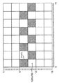
図13〜16を参照すると、3つのピクセルグリッドの一部が示されている。グリッド1と呼ばれ、左斜線で描かれた第1のピクセルグリッドの一部が示されている。グリッド2と呼ばれ、右斜線で描かれた第2のピクセルグリッドの一部が示されている。グリッド3と呼ばれ、交差斜線(つまり、左斜線と右斜線との両方)で描かれた第3のピクセルグリッドの一部が示されている。3つの部分は、同一の広がりを持ち、したがって、ピクチャの同じ部分を表す。3つの部分が同一の広がりを持つという事実が、互いに重なる3つの部分を示す図13に示されている。対照的に、図14〜16は、3つの部分のうちの1つだけを示す。図14は、グリッド1の部分を分離して示す。図15は、グリッド2の部分を分離して示す。図16は、グリッド3の部分を分離して示す。
With reference to FIGS. 13-16, a portion of three pixel grids is shown. A part of the first pixel grid, which is called
3つのピクセルグリッドは、3つの異なる解像度を有する。グリッド1は、解像度1920×1080を有する。グリッド2は、解像度1440×1080を有する。グリッド3は、解像度1280×720を有する。したがって、グリッド1は、最も高い水平解像度を有し、さらに、最も高い総解像度を有する。グリッド3は、最も低い(水平、垂直、および総)解像度を有する。グリッド2は、中間の水平解像度および総解像度を有する。ピクセルグリッドのそれぞれにおいて、一部のピクセルは、各グリッドのピッチをよりはっきりと示すために適切な線で斜線が引かれている。「ピッチ」は、概して、ピクセルのサイズおよび位置、ピクセルの間隔、または空間周波数(spatial frequency)を指すと理解される。
The three pixel grid has three different resolutions. The
図13〜16は、VU単位およびDU単位をそれぞれ示す縦軸および横軸も含む。VU単位およびDU単位は、図13〜16の3つの解像度に関して、既に説明されたように決定される。したがって、グリッド1の各ピクセルは、幅6DU×高さ2VUである。グリッド2の各ピクセルは、幅8DU×高さ3VUである。グリッド3の各ピクセルは、幅9DU×高さ3VUである。
FIGS. 13-16 also include a vertical axis and a horizontal axis indicating VU units and DU units, respectively. VU units and DU units are determined as described above for the three resolutions of FIGS. Therefore, each pixel of the
図13から理解され得るように、3つのグリッドすべての垂直なピクセル境界は、6VU(2VUと3VUとのSCM)ごとに整合する。3つのグリッドすべての水平なピクセル境界は、72DU(6DUと、8DUと、9DUとのSCM)ごとに整合する。 As can be seen from FIG. 13, the vertical pixel boundaries of all three grids are aligned every 6VU (2VU and 3VU SCM). The horizontal pixel boundaries of all three grids are aligned every 72 DU (6 DU, 8 DU, 9 DU SCM).
したがって、さまざまな実装に関して、視差マップのセルは、高さが6VUの第1の整数倍であり、幅が72DUの第2の整数倍であるものとして定義される。セルの視差値は、グリッド1、グリッド2、またはグリッド3のいずれかのセルに対応するピクセル内の物体の視差を提供する。そのような実装において、セルの視差値は、ピクチャがグリッド1、グリッド2、およびグリッド3の3つの解像度の間で変換されるときに再計算される必要がない。むしろ、セルの視差値は、これら3つの所定のピクチャの解像度のすべてに当てはまる。
Thus, for various implementations, a parallax map cell is defined as having a first integer multiple of 6 VU and a width being a second integer multiple of 72 DU. The parallax value of the cell provides the parallax of the object in the pixel corresponding to any of the
セルへと分割された結果として得られた視差マップは、DUで表されたピクチャの幅をDUで表されたセルの幅で割った数に等しい数のセルの列を有する。セルの行の数は、VUで表されたピクチャの高さをVUで表されたセルの高さで割った数に等しい。 The resulting disparity map resulting from the division into cells has a number of columns of cells equal to the width of the picture represented by DU divided by the width of the cell represented by DU. The number of rows in a cell is equal to the height of the picture represented by VU divided by the height of the cell represented by VU.
図13に示された例において、6VUおよび72DUと乗算される第1の整数と第2の整数とが両方とも「1」である場合、図13に示されるグリッドの部分は、3つのスケール非依存視差マップのセルに対応し、各セルは幅72DUおよび高さ6DUである。これは、高さが低く幅広の視差マップのセルを生じることに留意されたい。これら3つのセルのそれぞれは、図13の幅全体に広がる。第1のセルは、0VUから6VUまで垂直方向に延びる。第2のセルは、6VUから12VUまで垂直方向に延びる。第3のセルは、12VUから18VUまで垂直方向に延びる。 In the example shown in FIG. 13, if both the first integer and the second integer multiplied by 6VU and 72DU are “1”, the portion of the grid shown in FIG. Corresponding to the cells of the dependent parallax map, each cell has a width of 72 DU and a height of 6 DU. Note that this results in a cell with a low and wide parallax map. Each of these three cells extends across the entire width of FIG. The first cell extends vertically from 0 VU to 6 VU. The second cell extends vertically from 6 VU to 12 VU. The third cell extends vertically from 12 VU to 18 VU.
代替的に、第1の整数が「3」であり、第2の整数が「1」である場合、図13に示される3つのグリッドの部分は、単一のスケール非依存視差マップのセルに対応する。この単一のセルの横軸および縦軸は、第1の整数が「1」である上記の例のセルよりも似通った表現を有する。より似通った表現が原因で、この例におけるセルのアスペクト比は、例えば、基礎となるデータのサイズによっては、いくつかの目的のためにより効果的である可能性がある。 Alternatively, if the first integer is “3” and the second integer is “1”, the portions of the three grids shown in FIG. 13 are combined into a single scale-independent disparity map cell. Correspond. The horizontal and vertical axes of this single cell have a more similar representation than the cell in the above example where the first integer is “1”. Due to a more similar representation, the cell aspect ratio in this example may be more effective for some purposes, for example depending on the size of the underlying data.
DUおよびVUが同じサイズである必要はないことに留意されたい。図13に関連して検討された例において、1つのVUは1つのDUよりも大きい。これは、例えば、72個の水平単位のそれぞれの幅が1DUであり、18個の垂直単位のそれぞれの高さが1VUである図13で理解され得る。1DU×1VUである領域(「マイクロピクセル(micropixel)」と呼ばれる)は、DUおよびVUが同じサイズではないので、この例においては正方形ではない。我々が検討したように、水平解像度のSCMが、いくつのDUが画像の水平幅を構成するかを設定するために使用され得る。同様に、そのような計算が、VUおよび画像の垂直方向の高さに関して行われ得る。概して、仮定されたディスプレイの結果として得られたマイクロピクセルが正方形のマイクロピクセルである必要はない。これは、DUのサイズとVUのサイズとが異なる可能性があるためである。マイクロピクセルが正方形ではないとしても、グリッド1およびグリッド3のピクセルは正方形であり、一方、グリッド2のピクセルは4:3の画素アスペクト比を有することに留意されたい。
Note that the DU and VU need not be the same size. In the example discussed in connection with FIG. 13, one VU is larger than one DU. This can be seen, for example, in FIG. 13 where the width of each of the 72 horizontal units is 1 DU and the height of each of the 18 vertical units is 1 VU. A region that is 1 DU × 1 VU (referred to as a “micropixel”) is not square in this example because the DU and VU are not the same size. As we have discussed, a horizontal resolution SCM can be used to set how many DUs make up the horizontal width of the image. Similarly, such calculations can be performed with respect to VU and the vertical height of the image. In general, the resulting micropixel of the hypothesized display need not be a square micropixel. This is because the DU size and the VU size may be different. Note that the pixels in
視差マップがスケール非依存視差マップとして提供されるとき、視差マップの値は、所定の解像度のいずれかの対応するピクチャに対して変更なしに使用され得る。したがって、例えば、変換プロセスは必要とされない。 When the disparity map is provided as a scale-independent disparity map, the value of the disparity map can be used without change for any corresponding picture of a given resolution. Thus, for example, no conversion process is required.
さまざまな実装において、スケール非依存視差マップは、セルごとに1つのピクセルだけを含むセルから構成されることに留意されたい。いくつかのそのような実装において、所定の解像度は、互いに整数倍である。これらの実装においては、最も粗い解像度の1ピクセルが、その他の(より粗さの少ない)解像度のそれぞれの整数個のピクセルに対応する。1つの特定の実装においては、最も粗い解像度の1ピクセルが、より細かい(より粗さの少ない)解像度のうちの1つの4ピクセルに対応する。 Note that in various implementations, the scale-independent disparity map consists of cells that contain only one pixel per cell. In some such implementations, the predetermined resolution is an integer multiple of each other. In these implementations, one pixel with the coarsest resolution corresponds to an integer number of pixels of each of the other (less coarse) resolutions. In one particular implementation, one pixel with the coarsest resolution corresponds to 4 pixels of one of the finer (less coarse) resolution.
スケール非依存視差マップのセルは、異なる実装においてさまざまな利点をもたらす。例えば、さまざまな実装において、スケール非依存視差マップのセルは、解像度が変更されるとき、視差値を変換する必要性を完全になくす。別の例として、さまざまな実装において、スケール非依存視差マップのセルは、視差値と視差値が当てはまる関連する内容(例えば、物体)との間の対応を維持する。これらの利点は、以下でさらに検討される。 Scale independent disparity map cells offer various advantages in different implementations. For example, in various implementations, scale-independent disparity map cells completely eliminate the need to convert disparity values when the resolution is changed. As another example, in various implementations, a cell of a scale-independent disparity map maintains a correspondence between the disparity value and the associated content (eg, object) to which the disparity value applies. These advantages are further discussed below.
我々は、最初に、視差値の変換について検討する。再び図10を参照して、ピクセルP11〜P16からなるように定義されたピクセルのグループと同一の広がりを持つようにセルのサイズが選択されると仮定する。マップ2の解像度に変換すると、マップ1のセルの境界がマップ2のいずれのあり得る(完全なピクセルの)セル境界とも完全に一列に揃わないことは明らかである。したがって、例えば、ピクセルP24を含むセルの視差値は、おそらく、P11〜P16に関するマップ1のセルの視差と、ピクセルP18〜P19を含むマップ1のセルの視差とに基づく。そのような変換は、追加の処理リソースを必要とする。
We first consider the conversion of disparity values. Referring again to FIG. 10, assume that the cell size is selected to have the same extent as the group of pixels defined to be composed of pixels P11-P16. Converting to Map 2 resolution, it is clear that the cell boundaries of
しかし、すべての解像度のピクセル境界で整合するセル境界を提供することによって、すべての解像度のセルの視差値は、セルの外の領域の視差値を考慮する必要がない。加えて、視差値自体が、解像度のSCMに基づいており、したがって、現在の(しかし最終的ではない)解像度を反映するために変換される必要がない。確かに、さまざまな実装において、視差値は、例えば、字幕の配置などの処理の前のいかなる時点においても変換される必要がない。 However, by providing a cell boundary that matches at the pixel boundaries of all resolutions, the parallax values of cells of all resolutions need not take into account the parallax values of regions outside the cell. In addition, the disparity value itself is based on the resolution SCM and therefore does not need to be converted to reflect the current (but not final) resolution. Certainly, in various implementations, the disparity value does not need to be converted at any time prior to processing, such as subtitle placement.
ここで、我々は、視差値と内容との間の対応について検討する。再び図10を参照して、ピクセルP11〜P19およびピクセルP21〜P24が、すべて、ピクセルではなくセルであると仮定する。セルP15が最も小さな視差を有し、前景の物体を含むピクセルに対応するとさらに仮定する。視差の最小値計算を用いてマップ1からマップ2に変換すると、セルP15の視差が、セルP21〜P24に適用される。逆にマップ2からマップ1に再変換すると、セルP21〜P24の視差が、セルP11〜P19のすべてに適用される。したがって、2つの変換において、セルP15の視差が、セルP11〜P19の領域全体に広がっている。
Here we consider the correspondence between disparity values and content. Referring again to FIG. 10, assume that pixels P11-P19 and pixels P21-P24 are all cells rather than pixels. Assume further that cell P15 has the smallest parallax and corresponds to a pixel containing a foreground object. When the
そのような2つの変換の例は、例えば、典型的な送信環境で起こり得る。1つの実装において、ピクチャは、送信機の処理チェーン(例えば、処理チェーン810の検討を参照)によって使用される解像度に変換される。そして、受信されたピクチャは、逆に元の解像度に変換される(例えば、ビデオ画像817の検討を参照)。実際、その他の実装は、追加の変換を含む。例えば、1つの実装においては、(i)受信され、変換されたピクチャが、ピクチャをより低い解像度に変換する(第3の変換)小型スクリーンデバイス(例えば、セル電話)に提供され、(ii)次に、ユーザが、小型スクリーンデバイスからピクチャを送信し、これは、送信解像度への第4の変換を含み、(iii)ユーザの友人が、送信を受信し、ピクチャを表示する前にピクチャを変換する(第5の変換)。変換の回数が増えるにつれて、最小の視差が次第に広がって、グリッドのうちのますます多くの部分を占める可能性がある。
Two such conversion examples may occur, for example, in a typical transmission environment. In one implementation, the picture is converted to the resolution used by the transmitter's processing chain (see, for example,
最小の視差の範囲が広がることの1つの影響は、字幕の配置が換わる可能性があることである。例えば、元のピクチャにおいて、ピクセルP15内の物体は、ほとんど関心のない前景の歩道である可能性がある。ピクセルP12内の人は、背景にいるが、注目の的である可能性がある。元のピクチャにおいて、字幕は、字幕テキストであり、人の見かけのデプスと同様の見かけのデプスで配置されるように意図される可能性がある。しかし、上述の2つの変換の後、ピクセルP12内の人の示される視差は、今や、ピクセルP15の前景の歩道と同じである。したがって、字幕テキストは、人の近くに、ただし、歩道と同じである見かけのデプスで配置されることになる。そのような結果は、視聴者に不快感を与える可能性がある。 One effect of increasing the minimum parallax range is that the placement of subtitles may change. For example, in the original picture, the object in pixel P15 may be a foreground sidewalk with little interest. The person in pixel P12 is in the background but may be the center of attention. In the original picture, the subtitles are subtitle text and may be intended to be arranged with an apparent depth similar to the human apparent depth. However, after the two transformations described above, the parallax shown by the person in pixel P12 is now the same as the foreground sidewalk of pixel P15. Thus, the subtitle text will be placed near the person, but with an apparent depth that is the same as the sidewalk. Such a result can be uncomfortable for the viewer.
上記の複数の変換の実装は、確かにさまざまな利点をもたらすことに留意されたい。加えて、さまざまな実装が、さらなる利点をもたらす可能性がある異なる視差変換関数を使用する。 It should be noted that the implementation of multiple transformations described above certainly provides various advantages. In addition, various implementations use different disparity transformation functions that may provide additional benefits.
一部の実装は、それら自体が分離されており、隣接していないセルを使用することに留意されたい。そのような実装においては、視差値は、必ずしも、より大きなセルの領域に関連付けられる必要がない。例えば、セルのサイズが削減される可能性がある。しかし、異なる解像度のセルが境界のすべてで一列に揃わないとすると、通常、基礎となる内容の何らかの不一致が存在する。したがって、そのような実装は、概して、いくつかの利点をもたらすが、必ずしもスケール非依存視差セルの利点のすべてをもたらすとは限らない。 Note that some implementations are separate themselves and use non-adjacent cells. In such an implementation, the disparity value does not necessarily have to be associated with a larger cell area. For example, the cell size may be reduced. However, if the cells with different resolutions do not line up at all of the boundaries, there is usually some discrepancy in the underlying content. Thus, such an implementation generally provides several advantages, but not necessarily all of the advantages of scale independent disparity cells.
図17を参照すると、プロセス1700が与えられている。プロセス1700は、スケール非依存視差マップの生成および使用のさまざまな態様を扱う。
Referring to FIG. 17, a
プロセス1700は、どの解像度をサポートすべきかを決定すること(1705)を含む。例えば、本出願で検討される1または複数の実装においては、解像度1280×720、1440×1080、および1920×1080がサポートされる。
プロセス1700は、スケール非依存セルのサイズを決定すること(1710)を含む。例えば、3つの解像度1280×720、1440×1080、および1920×1080に関して、最も小さなスケール非依存セルのサイズは、SCM解像度11,520×2160に基づいて72DU×6VUである。最も小さなスケール非依存セルのサイズに関する、1または複数の実装において使用される式は、
であり、ここで、この例に関しては、R1、R2、およびR3は、対象の水平解像度かまたは垂直解像度かのどちらかであり、N=3であり、「r」は、(水平が考慮されているのかまたは垂直が考慮されているのかに応じてDUまたはVUでの)単位数である。したがって、例示的な水平解像度1280、1440、および1920に関して、内側の分子は、11,520であるSCM(1280,1440,1920)になり、式は、
Where, for this example, R 1 , R 2 , and R 3 are either horizontal or vertical resolution of interest, N = 3, and “r” is (horizontal Is the number of units (in DU or VU) depending on whether or not vertical is considered. Thus, for the exemplary
になる。 become.
垂直解像度に関する同様の計算は、結果が6になる。したがって、スケール非依存セルのサイズは、(この場合)72DUの整数倍である幅と、(この場合)6VUの整数倍である高さとを用いて選択される可能性がある。 A similar calculation for vertical resolution results in 6. Thus, the size of the scale independent cell may be selected using a width that is an integer multiple of 72 DU (in this case) and a height that is an integer multiple of 6 VU (in this case).
プロセス1700は、例えば、密な視差マップを受信することによって密な視差マップにアクセスすること(1715)を含む。その他の実装は、視差値を推定すること、または受信されるかもしくは推定されるかのどちらかのデプス値に基づいて視差値を計算することによって密な視差マップを生成する。さらに他の実装は、密な視差マップにアクセスしない。
プロセス1700は、1または複数のセルの視差値を決定すること(1720)を含む。セルの視差値は、例えば、密な視差マップからの視差値に対する(本出願に記載の)平均関数または最小値関数を使用することによって決定される。
プロセス1700は、1または複数のセルの視差値をSCM視差値にアップコンバートすること(1725)を含む。1つの実装においては、動作1720において決定されたセルの視差値が、この動作1725においてSCM視差値にアップコンバートされる。異なる実装においては、ピクセルに基づく視差値が、動作1720の前にSCM視差値にアップコンバートされる。したがって、異なる実装においては、動作1720において生成された1または複数のセルの視差値が既にSCM視差値であり、動作1725が省略される。
プロセス1700は、スケール非依存視差マップをフォーマットすること(1730)を含む。スケール非依存視差マップは、異なる実装においてさまざまな異なる方法でフォーマットされる。いくつかの例がこの後に続き、それらのそれぞれは、所与の視差マップのセルのSCMに基づくスケール非依存視差値をフォーマットする。
第1のフォーマットの実装においては、(i)特定の解像度のみがサポートされ、(ii)特定のセルのサイズのみが使用されなければならず、(iii)セルの視差値が特定のセルの順番でフォーマットされなければならないことが理解される。したがって、例えば、セルのサイズのDUおよびVUと、視差マップ内のセルの数とが、決定され得る。この第1のフォーマットの実装においては、スケール非依存視差マップは、以下の擬似コードを用いて形成される。
for(i=0;i<“セルの数”;i++){
cell(i)に関するSCMに基づくスケール非依存視差}
In the first format implementation, (i) only a specific resolution is supported, (ii) only the size of a specific cell must be used, and (iii) the disparity value of the cell is the order of the specific cell It is understood that it must be formatted with Thus, for example, the cell size DU and VU and the number of cells in the disparity map may be determined. In the implementation of the first format, the scale-independent disparity map is formed using the following pseudo code.
for (i = 0; i <“number of cells”; i ++) {
SCM-based scale-independent disparity for cell (i)}
第2のフォーマットの実装においては、異なるセルのサイズがサポートされる。しかし、それぞれのセルのサイズに関して、セルの視差値が、特定のセルの順番でフォーマットされなければならない。したがって、この第2のフォーマットの実装は、セルのサイズを選択し、それが、視差マップ内のセルの数を決定する。セルのサイズの選択は、「セルサイズフラグ(cell size flag)」を用いて示される。例えば、4つの異なるセルのサイズがサポートされる場合、2ビットのフラグが、セルのサイズの選択を指示するために使用される。この第2のフォーマットの実装においては、スケール非依存視差マップは、以下の擬似コードを用いて形成される。
“セルサイズフラグ”;
for(i=0;i<“セルの数”;i++){
cell(i)に関するSCMに基づくスケール非依存視差}
In the second format implementation, different cell sizes are supported. However, for each cell size, the cell disparity values must be formatted in a specific cell order. Thus, this second format implementation selects the size of the cell, which determines the number of cells in the disparity map. The selection of the cell size is indicated using a “cell size flag”. For example, if four different cell sizes are supported, a 2-bit flag is used to indicate the selection of the cell size. In the implementation of the second format, the scale-independent parallax map is formed using the following pseudo code.
“Cell size flag”;
for (i = 0; i <“number of cells”; i ++) {
SCM-based scale-independent disparity for cell (i)}
第1のフォーマットの実装の変更形態においては、完全な視差マップが、第1のフォーマットの実装を用いて形成される。しかし、1または複数のセルの視差値を変更する更新は、新しい視差マップ全体を形成することなく形成され得る。この変更形態においては、「更新されるセルの数」と、これらの更新されるセルのそれぞれの「セル番号」とが与えられる。この変更形態においては、スケール非依存視差マップに対する更新は、以下の擬似コードを用いて形成される。
“更新されるセルの数”;
for(i=0;i<“更新されるセルの数”;i++){
“セル番号”(i);
cell(i)に関するSCMに基づくスケール非依存視差}
In a variation of the first format implementation, a complete disparity map is formed using the first format implementation. However, updates that change the disparity value of one or more cells can be formed without forming an entire new disparity map. In this modification, the “number of cells to be updated” and the “cell number” of each of these updated cells are given. In this modification, the update to the scale-independent parallax map is formed using the following pseudo code.
“Number of cells to be updated”;
for (i = 0; i <“number of cells to be updated”; i ++) {
“Cell number” (i);
SCM-based scale-independent disparity for cell (i)}
第3のフォーマットの実装においては、限られた数のセルのみが使用される。特定のセルのサイズが、上述の第1のフォーマットの実装のように使用されると仮定される。しかし、視差値は、例えば、物体のコーナーまたは物体のエッジなどの対象の特徴を含むセルに関してのみ計算される。この第3のフォーマットの実装においては、使用される「セルの数」が決定され、セル識別子も決定される。セル識別子は、この第3のフォーマットの実装の1つの変更形態においては、例えば、例えばDUおよびVUで表された左上隅のピクセルおよび右下隅のピクセルの座標などの各セルの座標である。別の変更形態において、セル識別子は「セル番号」である。この第3のフォーマットの実装のさらに他の変更形態においては、複数のセルのサイズが使用可能であり、「セルサイズフラグ」が、上述の第2のフォーマットの実装で示されたように、選択されたセルのサイズを指示するために使用される。この第3のフォーマットの実装の1つの変更形態においては、スケール非依存視差マップは、以下の擬似コードを用いて形成される。
“セルの数”;
for(i=0;i<“セルの数”;i++){
“セル番号”(i);
cell(i)に関するSCMに基づくスケール非依存視差}
In the third format implementation, only a limited number of cells are used. It is assumed that the size of a particular cell is used as in the first format implementation described above. However, disparity values are calculated only for cells that include the feature of interest, such as, for example, a corner of an object or an edge of an object. In the implementation of this third format, the “number of cells” to be used is determined and the cell identifier is also determined. The cell identifier, in one variation of this third format implementation, is the coordinates of each cell, for example, the coordinates of the upper left corner pixel and the lower right corner pixel represented by DU and VU, for example. In another variation, the cell identifier is a “cell number”. In yet another variation of this third format implementation, multiple cell sizes can be used, and the “cell size flag” can be selected as shown in the second format implementation above. Used to indicate the size of the assigned cell. In one variation of this third format implementation, the scale-independent disparity map is formed using the following pseudo code:
“Number of cells”;
for (i = 0; i <“number of cells”; i ++) {
“Cell number” (i);
SCM-based scale-independent disparity for cell (i)}
プロセス1700は、スケール非依存視差マップを符号化すること(1735)を含む。スケール非依存視差マップは、例えば、SCMに基づく視差マップ、またはただ1つのディスプレイ解像度に関して生成された視差を提供する視差マップである。
プロセス1700は、スケール非依存視差マップを記憶することおよび/または送信すること(1740)を含む。スケール非依存視差マップは、例えば、符号化されたSCMに基づく視差マップ、符号化されたSCMに基づかない視差マップ、符号化されていないSCMに基づく視差マップ、または符号化されていないSCMに基づかない視差マップである。特定のアプリケーションにおいては、符号化されていない視差マップが記憶され、符号化された視差マップが送信される。したがって、1つのアプリケーションにおいては、動作1730からのフォーマットされた視差マップが記憶され、さらに符号化され、動作1735からの符号化された視差マップが送信される。
プロセス1700は、スケール非依存視差マップにアクセスすること(1745)を含む。1つの実装において、動作1745は、送信された符号化されたスケール非依存視差マップを受信することによってスケール非依存視差マップにアクセスする受信機で行われる。別の実装においては、動作1745は、記憶されたスケール非依存視差マップを取得することによってスケール非依存視差マップにアクセスするポストプロセッサーで行われる。ポストプロセッサーは、例えば、字幕に関する視差および/またはデプスを決定することなど、視差マップを使用する処理を実行するために視差マップを取得する。
プロセス1700は、スケール非依存視差マップを復号すること(1750)を含む。1つの実装において、動作1750は、受信機が、伝送チャネルを介して視差マップを受信した後、符号化されたスケール非依存視差マップを復号することを含む。
プロセス1700は、解像度を選択すること(1755)を含む。1つの実装において、解像度は、いくつかのサポートされる解像度の中から選択される。例えば、水平解像度1920が、1280、1440、および1920の中から選択される。
プロセス1700は、1または複数のSCMに基づく視差値を特定の解像度にダウンコンバートすること(1760)を含む。1つの実装において、SCMに基づくスケール非依存視差マップは、SCMによってサポートされるいくつかの解像度の中から選択された解像度にダウンコンバートされる。例えば、SCM11,520に基づく視差値が、視差値を6で割ることによって水平解像度1920にダウンコンバートされる。
プロセス1700は、1または複数のセルを対応するピクセル位置に関連付けること(1765)を含む。1つの実装においては、SCMに基づくスケール非依存視差セルが、所与の解像度のピクチャ内の対応するピクセル位置にマッピングされる。さらに、所与の解像度は、SCMによってサポートされるいくつかの解像度から選択される。そのような実装は、例えば、特定のセルに関する視差が、対応するピクチャ内の特定のピクセル位置とそれらのピクセル位置に示される物体とによって特定されることを可能にする。1つの実装においては、SCM解像度11,520×2160が、セルのサイズ72DU×6VUとともに使用される。この実装においては、セルは、例えば、(72DU,6VU)で始まるセルのように、その左上のコーナーの(DU,VU)座標によって特定される。そのセルに関連するピクセル位置は、セルの(DU,VU)座標をピクセルの(DU,VU)サイズで割ることによって決定される。解像度1920×1080が選択される場合、既に説明されたように、ピクセルサイズは(6DU,2VU)である。この実装に関して、(72DU,6VU)のセルに関連するピクセル位置は、ピクセル位置(12,3)から始まり、ピクセル位置(24,6)まで延びる(ただしこのピクセル位置を含まない)ピクセルである。
プロセス1700は、1または複数の関連する視差値を使用してピクチャを処理すること(1770)を含む。1つの実装において、視差マップからの視差値は、対応するピクチャ内のピクセル位置に関連付けられる。ピクチャはピクチャのステレオ画像のペアの一部であり、ステレオ画像のペアの各ピクチャは字幕を含む。ステレオ画像のペアのピクチャのうちの少なくとも一方は、字幕のピクセル位置に関連する視差値によって示される視差の量を字幕に与えるように処理される。
図18を参照すると、プロセス1800が示されている。プロセス1800は、解像度不変領域に関する解像度に固有の属性を決定すること(1810)を含む。解像度に固有の属性は、解像度に依存する値を有する属性である。視差は、解像度に依存する属性の例である。
Referring to FIG. 18, a
その他の解像度に固有の属性は、例えば、「粒状性(graininess)」または「テクスチャ特性(texture characteristics)」を含む。特定の実装においては、さまざまなテクスチャ特性が、いくつかのピクセルによって定義される。例えば、1つの実装においては、平均粒子サイズ(grain size)および標準偏差が、ピクセルを単位として定義される。別の実装においては、繰り返しの多いテクスチャのピッチが、ピクセルを単位として定義される。 Other resolution specific attributes include, for example, “graininess” or “texture characteristics”. In certain implementations, various texture characteristics are defined by several pixels. For example, in one implementation, the average particle size and standard deviation are defined in units of pixels. In another implementation, the pitch of repetitive textures is defined in units of pixels.
別の解像度に固有の属性は、例えば、ピクセルで表される確実性または信頼性である。1つの実装においては、確実性/信頼性は、ピクセルで計測される予測される誤差を表す。 Another resolution specific attribute is, for example, certainty or reliability expressed in pixels. In one implementation, the certainty / reliability represents the expected error measured at the pixel.
解像度不変領域は、第1の解像度において第1の整数個のピクセルと同一の広がりを持ち、第2の解像度において第2の整数個のピクセルと同一の広がりを持つ(例えば、ピクチャの)領域である。動作1810は、1つの実装においては、1または複数のセルの視差値を決定する動作1720によって実行される。
A resolution-invariant region is a region (eg, a picture) that has the same extent as the first integer number of pixels at the first resolution and the same extent as the second integer number of pixels at the second resolution. is there.
プロセス1800は、組み合わせ解像度に関連するように属性を変換すること(1820)を含む。組み合わせ解像度は、第1の解像度と第2の解像度との組み合わせとして決定された解像度である。変換された属性は、領域に固有であり、組み合わせ解像度にも固有である。動作1820は、1つの実装においては、1または複数のセルの視差値をSCM視差値にアップコンバートする動作1725によって実行される。
図19を参照すると、プロセス1900が示されている。プロセス1900は、ピクチャの解像度不変領域に関する組み合わせ解像度に固有の属性にアクセスすること(1910)を含む。属性は、解像度に依存する値を含んでおり、組み合わせ解像度および領域に固有である。加えて、解像度不変領域は、特定の解像度において第1の整数個のピクセルと同一の広がりを持ち、第2の解像度において第2の整数個のピクセルと同一の広がりを持つ(例えば、ピクチャの)領域である。さらに、組み合わせ解像度は、特定の解像度と第2の解像度との組み合わせとして決定された解像度である。動作1910は、1つの実装においては、スケール非依存視差マップにアクセスする動作1745によって実行される。
Referring to FIG. 19, a
プロセス1900は、属性が特定の解像度に関連するようにそれを変換すること(1920)を含む。変換された属性は、領域および特定の解像度に固有である。動作1920は、1つの実装においては、1または複数のSCMに基づく視差値を特定の解像度にダウンコンバートする動作1760によって実行される。
プロセス1900は、変換された属性を特定の解像度の領域のピクセルに関連付けること(1930)を含む。変換された属性は、特定の解像度の第1の整数個のピクセルに関連付けられる。動作1930は、1つの実装においては、1または複数のセルを対応するピクセル位置に関連付ける動作1765によって実行される。
ここで図20を参照すると、上述の特徴および原理が適用され得るビデオ送信システムまたは装置2000が示されている。ビデオ送信システムまたは装置2000は、例えば、衛星、ケーブル、電話回線、または地上波放送などのさまざまな媒体のいずれかを使用して信号を送信するための、例えば、ヘッドエンドまたは送信システムである可能性がある。ビデオ送信システムまたは装置2000は、さらに、または代替的に、例えば、記憶するための信号を提供するために使用される可能性がある。送信は、インターネットまたは何らかのその他のネットワークを介して行われ得る。ビデオ送信システムまたは装置2000は、例えば、デプスおよび/または視差値を含む、例えば、デプスのインジケータなどの、例えば、ビデオコンテンツおよびその他のコンテンツを生成し、配信することができる。図20のブロックが、ビデオ送信システムまたは装置のブロック図を提供することに加えて、ビデオ送信プロセスのフロー図を提供することは明らかであるに違いない。
Referring now to FIG. 20, a video transmission system or
ビデオ送信システムまたは装置2000は、プロセッサー2001から入力ビデオを受信する。1つの実装において、プロセッサー2001は、単純に、視差画像821、831、841、および/またはビデオ画像811などの元の解像度の画像をビデオ送信システムまたは装置2000に与える。しかし、別の実装においては、プロセッサー2001は、例えば、ビデオ画像813および/または視差画像823、833、843などの画像を提供するための動作812、822、832、842に関連して上で説明されたように濾波およびダウンサンプリングを実行するように構成されたプロセッサーである。さらに別の実装においては、プロセッサー2001は、例えば、視差画像860などの変換された視差値を有する視差画像を生成するための、例えば、動作850などの視差変換を実行するように構成される。さらに別の実装においては、プロセッサー2001は、プロセス1700のさまざまな動作、例えば、動作1705〜1730を実行するように構成される。さらに別の実装においては、プロセッサー2001は、プロセス1800のすべてまたは一部を実行するように構成される。さらに、プロセッサー2001は、ビデオ送信システムまたは装置2000にメタデータを提供し、例えば、入力画像の水平解像度と、視差値が基づく水平解像度と、視差値が百分率に基づくのか、または公倍数に基づくのかと、入力画像のうちの1つまたは複数を示すその他の情報とを示す可能性がある。
Video transmission system or
ビデオ送信システムまたは装置2000は、符号化器2002と、符号化された信号を送信することができる送信機2004とを含む。符号化器2002は、プロセッサー2001からビデオ情報を受信する。ビデオ情報は、例えば、ビデオ画像および/または視差(もしくはデプス)画像を含む可能性がある。符号化器2002は、ビデオ情報および/または視差情報に基づいて(1または複数の)符号化された信号を生成する。符号化器2002は、例えば、AVC符号化器である可能性がある。AVC符号化器は、ビデオ情報と視差情報との両方に適用され得る。AVCは、既存の国際標準化機構/国際電気標準会議(ISO/IEC)の動画専門家グループ−4(MPEG−4:Moving Picture Experts Group−4)パート10 高度ビデオ符号化(AVC:Advanced Video Coding)規格/国際電気通信連合、電気通信部門(ITU−T)H.264勧告(以降、「H.264/MPEG−4 AVC規格」、または「AVC規格」、「H.264規格」、もしくは単に「AVC」または「H.264」などのその変形)を指す。
Video transmission system or
符号化器2002は、例えば、さまざまな情報を受信し、それらの情報を記憶または送信のための構造化されたフォーマットへと組み立てるための組立ユニットを含むサブモジュールを含む可能性がある。さまざまな情報は、例えば、符号化されたまたは符号化されていないビデオと、符号化されたまたは符号化されていない視差(またはデプス)値と、例えば、動きベクトル、符号化モードインジケータ(coding mode indicator)、および構文要素(syntax element)などの符号化されたまたは符号化されていない要素とを含む可能性がある。一部の実装において、符号化器2002は、プロセッサー2001を含み、したがって、プロセッサー2001の動作を実行する。
Encoder 2002 may include, for example, sub-modules that include assembly units for receiving various information and assembling the information into a structured format for storage or transmission. Various information includes, for example, encoded or unencoded video, encoded or unencoded disparity (or depth) values, eg, motion vectors, coding mode indicators (coding mode). and encoded and non-encoded elements such as syntax elements. In some implementations, the
送信機2004は、符号化器2002から(1または複数の)符号化された信号を受信し、1または複数の出力信号で(1または複数の)符号化された信号を送信する。送信機2004は、例えば、符号化されたピクチャおよび/またはそれに関連する情報を表す1または複数のビットストリームを有するプログラム信号を送信するように適合され得る。典型的な送信機は、例えば、誤り訂正符号化を行うことと、信号のデータをインターリーブすることと、信号のエネルギーをランダム化することと、変調器2006を使用して信号を1もしくは複数の搬送波に変調することとのうちの1つまたは複数などの機能を実行する。送信機2004は、アンテナ(図示せず)を含むか、またはアンテナ(図示せず)とインターフェースを取ることができる。さらに、送信機2004の実装は、変調器2006に限られる可能性がある。
The
さらに、ビデオ送信システムまたは装置2000は、記憶ユニット2008に通信可能なように結合される。1つの実装において、記憶ユニット2008は、符号化器2002に結合され、符号化器2002からの符号化されたビットストリームを記憶する。別の実装においては、記憶ユニット2008は、送信機2004に結合され、送信機2004からのビットストリームを記憶する。送信機2004からのビットストリームは、例えば、送信機2004によってさらに処理された1または複数の符号化されたビットストリームを含む可能性がある。記憶ユニット2008は、異なる実装においては、標準的なDVD、ブルーレイディスク、ハードドライブ、または何らかのその他の記憶装置のうちの1つまたは複数である。
Further, the video transmission system or
ここで図21を参照すると、上述の特徴および原理が適用され得るビデオ受信システムまたは装置2100が示されている。ビデオ受信システムまたは装置2100は、例えば、衛星、ケーブル、電話回線、または地上波放送などのさまざまな媒体を介して信号を受信するように構成され得る。信号は、インターネットまたは何らかのその他のネットワークを介して受信される可能性がある。図21のブロックが、ビデオ受信システムまたは装置のブロック図を提供することに加えて、ビデオ受信プロセスのフロー図を提供することは明らかであるに違いない。
Referring now to FIG. 21, a video receiving system or
ビデオ受信システムまたは装置2100は、例えば、セル電話、コンピュータ、セットトップボックス、ルータ、テレビ、または符号化されたビデオを受信し、例えば、復号されたビデオ信号を、表示する(例えば、ユーザに対して表示する)ため、処理するため、または記憶するために提供するその他のデバイスである可能性がある。したがって、ビデオ受信システムまたは装置2100は、その出力を、例えば、テレビのスクリーン、コンピュータモニター、(記憶、処理、もしくは表示するための)コンピュータ、または何らかのその他の記憶、処理、もしくはディスプレイ装置に提供することができる。
The video receiving system or
ビデオ受信システムまたは装置2100は、ビデオ情報を受信し、処理することができ、ビデオ情報は、例えば、ビデオ画像および/または視差(もしくはデプス)画像を含む可能性がある。ビデオ受信システムまたは装置2100は、例えば、本出願の実装で示された信号などの符号化された信号を受信するための受信機2102を含む。受信機2102は、例えば、ビデオ画像815および/もしくは視差画像825のうちの1つもしくは複数を提供する信号、または図20のビデオ送信システム2000から出力された信号を受信することができる。1つの実装において、受信機2102は、動作1730に関連して検討された擬似コードの実装のうちの1つまたは複数にしたがって形成されたデータを提供する信号を受信する。別の実装においては、受信機2102は、プロセス1800の出力からのデータを提供する信号を受信する。
A video receiving system or
受信機2102は、例えば、符号化されたピクチャを表す複数のビットストリームを有するプログラム信号を受信するように適合され得る。典型的な受信機は、例えば、変調され、符号化されたデータ信号を受信することと、復調器2104を使用して1もしくは複数の搬送波からデータ信号を復調することと、信号のエネルギーのランダム化を解除することと、信号のデータのインターリーブを解除することと、信号を誤り訂正復号することとのうちの1つまたは複数などの機能を実行する。受信機2102は、アンテナ(図示せず)を含むか、またはアンテナ(図示せず)とインターフェースを取ることができる。受信機2102の実装は、復調器2104に限られる可能性がある。
ビデオ受信システムまたは装置2100は、復号器2106を含む。受信機2102は、受信された信号を復号器2106に与える。受信機2102によって復号器2106に与えられる信号は、1または複数の符号化されたビットストリームを含み得る。復号器2106は、例えば、ビデオ情報を含む復号されたビデオ信号などの復号された信号を出力する。復号器2106は、例えば、AVC復号器である可能性がある。
Video receiving system or
さらに、ビデオ受信システムまたは装置2100は、記憶ユニット2107に通信可能なように結合される。1つの実装において、記憶ユニット2107は、受信機2102に結合され、受信機2102が、記憶ユニット2107からのビットストリームにアクセスする。別の実装においては、記憶ユニット2107は、復号器2106に結合され、復号器2106が、記憶ユニット2107からのビットストリームにアクセスする。記憶ユニット2107からのアクセスされるビットストリームは、異なる実装においては、1または複数の符号化されたビットストリームを含む。記憶ユニット2107は、異なる実装においては、標準的なDVD、ブルーレイディスク、ハードドライブ、または何らかのその他の記憶装置のうちの1つまたは複数である。
Further, the video receiving system or
1つの実装においては、復号器2106からの出力ビデオが、プロセッサー2108に与えられる。プロセッサー2108は、1つの実装においては、例えば、アップサンプリング動作816および/または826に関連して説明されたアップサンプリングなどのアップサンプリングを実行するように構成されたプロセッサーである。別の実装においては、プロセッサー2108は、例えば、動作1755〜1765のすべてもしくは一部、またはプロセス1900を実行するように構成される。別の実装においては、プロセッサー2108は、例えば、動作1770、または例えばプロセス1900の出力によって与えられた視差値および関連する情報を使用する後処理などの後処理を実行するように構成される。
In one implementation, the output video from
一部の実装において、復号器2106は、プロセッサー2108を含み、したがって、プロセッサー2108の動作を実行する。その他の実装においては、プロセッサー2108は、例えば、セットトップボックス、ルータ、コンピュータ、タブレットまたはテレビなどのダウンストリームデバイスの一部である。
In some implementations, the
その他の実装は、本出願において与えられた例によって想定されている。例えば、解像度960×640、1280×720、1440×1080、および1920×1080のSCMは、11,520×17,280である。「17,280」は、例えば、本出願で上述した11,520と同じようにして計算される。「17,280」は、640*27に等しい。このSCMは、ピクセルサイズ12DU×27VU、9DU×24VU、8DU×16VU、および6DU×16VUをそれぞれもたらす。これらのピクセルサイズは、72DU(または整数倍)×432VU(または整数倍)のスケール非依存視差マップのセルサイズをもたらす。 Other implementations are envisioned by the examples given in this application. For example, the SCMs with resolutions of 960 × 640, 1280 × 720, 1440 × 1080, and 1920 × 1080 are 11,520 × 17,280. For example, “17,280” is calculated in the same manner as 11,520 described above in the present application. “17,280” is equal to 640 * 27. This SCM results in pixel sizes 12DU × 27VU, 9DU × 24VU, 8DU × 16VU, and 6DU × 16VU, respectively. These pixel sizes result in a cell size of the scale independent disparity map of 72 DU (or integer multiple) × 432 VU (or integer multiple).
少なくとも1つの実装は2つの視差マップが生成されることを可能にするために特別なビットを使用することに留意されたい。第1の視差マップは、「左の」像に関して計算され、第2の視差マップは、「右の」像に関して計算される。物体が隠蔽される可能性があるとすると、2つの視差マップを有することは、隠蔽の改善された処理を可能にする。例えば、対応する視差値を比較することによって、システムは、隠蔽が存在するかどうかを判定し、存在する場合、結果として生じる穴を埋めるためのステップを行うことができる。さらなる実装は、より多くの視差マップを提供し、視差マップの数に対応するように適切な数のビットを割当てる。例えば、例えばMVC(これは、MVC拡張付きのAVC(Annex G)を指す)などの多視点(multi−view)の状況においては、あらゆる視点からあらゆる他の視点への計算された視差を示す一組の視差マップを送信することが望ましい可能性がある。代替的に、実装は、視点のサブセットに関する視差マップのみを送信する可能性がある。 Note that at least one implementation uses special bits to allow two disparity maps to be generated. The first disparity map is calculated for the “left” image, and the second disparity map is calculated for the “right” image. Given that an object may be concealed, having two disparity maps allows for improved processing of concealment. For example, by comparing corresponding disparity values, the system can determine whether concealment exists and, if so, can take steps to fill the resulting hole. Further implementations provide more parallax maps and allocate an appropriate number of bits to correspond to the number of parallax maps. For example, in a multi-view situation such as, for example, MVC (which refers to AVC (Annex G) with MVC extension), one that indicates the calculated disparity from any viewpoint to any other viewpoint. It may be desirable to transmit a set of parallax maps. Alternatively, an implementation may send only a disparity map for a subset of viewpoints.
視差は、例えば、動きベクトルを計算するのと同様にして計算され得る。代替的に、視差は、知られており、上で説明されているように、デプス値から計算され得る。 The disparity can be calculated, for example, in the same way as calculating a motion vector. Alternatively, the parallax is known and can be calculated from the depth value, as described above.
また、さまざまな実装は、デプス値の代わりに視差値を使用することによる利点を有する。そのような利点は、(1)デプス値が限りなく大きくなる可能性があり、したがって、表現/符号化することがより難しい一方、視差値は有限であること、(2)潜在的に非常に大きなデプス値を表現するために、多くの場合、対数のスケール化が必要とされる一方、視差値は直接表現され得ることを含む可能性がある。加えて、視差からデプスを決定することは概して容易である。焦点距離、ベースライン距離(長さ)、および輻湊平面距離などの情報を提供するために、さまざまな実装にメタデータが含まれる。輻湊平面距離は、カメラが輻湊しているときにカメラの軸が交差する距離である。カメラの軸が交差する地点は、図4において、角410の頂点として見られ得る。カメラが平行であるときは、輻湊平面距離は、無限大の距離にある。
Various implementations also have the advantage of using disparity values instead of depth values. Such advantages include (1) the depth value can be infinitely large and therefore more difficult to represent / encode, while the disparity value is finite, (2) potentially very To represent large depth values, logarithmic scaling is often required, while disparity values can include being directly representable. In addition, it is generally easy to determine the depth from the parallax. Various implementations include metadata to provide information such as focal length, baseline distance (length), and convergence plane distance. The convergence plane distance is the distance at which the camera axes intersect when the camera is converging. The point where the camera axes intersect can be seen as the apex of
本出願に記載の実装は、さまざまな属性に適用され得る。1つのそのような属性は、視差である。 The implementation described in this application may be applied to various attributes. One such attribute is parallax.
− しかし、その他の実装は、解像度に固有であるその他の属性を使用する。既に説明されたように、解像度に固有の属性は、解像度に依存する値を有する属性である。視差は、解像度に依存する属性の例である。その他の例は、粒状性および信頼性を含む。 -However, other implementations use other attributes that are resolution specific. As described above, the resolution-specific attribute is an attribute having a value depending on the resolution. Parallax is an example of an attribute that depends on resolution. Other examples include graininess and reliability.
− さまざまな実装は、例えば、解像度に固有ではないデプスなどの属性を使用する。そのような属性は、解像度が変更されるときに修正される必要がないSCMに基づく視差値とある面では似ている。 -Various implementations use attributes such as depth that are not resolution specific, for example. Such attributes are similar in some respects to SCM-based parallax values that do not need to be modified when the resolution is changed.
解像度間の変換中に視差値を決定するために加重平均または最小値関数を使用するさまざまな実装が、記載されている。その他の実装は、例えば、非加重平均、最大値(最大の視差を使用する)、最頻値(mode)、中央値、内挿、またはさまざまな濾波関数のいずれかなどの異なる関数を使用する。 Various implementations have been described that use a weighted average or minimum value function to determine disparity values during conversion between resolutions. Other implementations use different functions such as, for example, unweighted average, maximum (using maximum disparity), mode, median, interpolation, or various filtering functions .
一部の実装は特定の利点または欠点を有することが留意される。しかし、実装の欠点の検討は、その実装の利点を消し去ることはなく、実装が、実現可能であり、さらには推奨される実装ではないことを示すこともない。 It is noted that some implementations have certain advantages or disadvantages. However, an examination of the shortcomings of an implementation does not erase the benefits of that implementation, nor does it indicate that the implementation is feasible or even not a recommended implementation.
さまざまな実装は、信号および/または信号の構造を生成または処理する。そのような信号は、特定の実装において、動作1730の検討で説明された擬似コードなどの擬似コードを使用して形成される。信号は、さまざまな実装において、プロセッサー2001、符号化器2002、送信機2004、受信機2102、復号器2106、またはプロセッサー2108の出力で生成される。信号および/または信号の構造は、さまざまな実装において(例えば、プロセッサー可読媒体で)送信および/または記憶される。
Various implementations generate or process signals and / or signal structures. Such a signal is formed using pseudo code, such as the pseudo code described in the discussion of
特定の実装において、信号または信号の構造は、ピクチャの領域に関する属性を示すデータを含む属性部分を含む。属性は、領域および組み合わせ解像度に固有である。組み合わせ解像度は、特定の解像度と第2の解像度との組み合わせとして決定される。ピクチャの領域は、特定の解像度において第1の整数個のピクセルと同一の広がりを持ち、第2の解像度において第2の整数個のピクセルと同一の広がりを持つ。 In certain implementations, the signal or signal structure includes an attribute portion that includes data indicating attributes relating to the region of the picture. Attributes are specific to the region and the combined resolution. The combination resolution is determined as a combination of the specific resolution and the second resolution. The region of the picture has the same extent as the first integer number of pixels at a particular resolution and the same extent as the second integer number of pixels at the second resolution.
加えて、その他の実装は、セルのサイズ、セルの位置、およびその他のメタデータに関連するデータに関する信号または信号の構造内の部分を含む。そのような信号は、さまざまな実装において、さまざまな方法のいずれかで符号化される。 In addition, other implementations include parts in the signal or signal structure regarding data related to cell size, cell location, and other metadata. Such a signal is encoded in any of a variety of ways in a variety of implementations.
本出願は、図6、8、および17〜21のブロック/フロー図を含む複数のブロック/フロー図を提供する。本出願のブロック/フロー図は、プロセスを示すフロー図と、装置の機能ブロックを示すブロック図との両方を示すことは明らかであるに違いない。加えて、本出願は、図1〜5の図形表現を含む複数の図形表現を提供する。本出願の図形表現は、(i)例、結果、または出力と、(ii)プロセスを示すフロー図との両方を示すことは明らかであるに違いない。加えて、本出願は、少なくとも、図7の表形式の図を提供する。表形式の図は、データの表を提供し、さらに、異なる解像度における視差値を得るためのプロセスを示すことは明らかであるに違いない。さらに、本出願は、図9〜16のブロック/図形表現を含む複数のブロック/図形表現を提供する。本出願のブロック/図形表現は、さまざまなデータフォーマットおよび解像度の態様を示すブロック図と、コンポーネントとコンポーネントの出力との間の関係を示す図形表現との両方を示すことは明らかであるに違いない。 This application provides a plurality of block / flow diagrams including the block / flow diagrams of FIGS. It should be clear that the block / flow diagram of the present application shows both a flow diagram showing the process and a block diagram showing the functional blocks of the device. In addition, the present application provides a plurality of graphical representations including the graphical representations of FIGS. It should be clear that the graphical representation of this application shows both (i) examples, results, or outputs, and (ii) a flow diagram illustrating the process. In addition, this application provides at least the tabular view of FIG. It should be clear that the tabular diagram provides a table of data and further shows the process for obtaining disparity values at different resolutions. In addition, this application provides a plurality of block / graphic representations including the block / graphic representations of FIGS. It should be clear that the block / graphic representation of this application presents both a block diagram showing aspects of various data formats and resolutions, and a graphical representation showing the relationship between components and component outputs. .
さらに、本出願で説明された実装の動作、ブロック、入力、または出力のうちの多くは、これらの実装の説明および検討で明確に述べられていないとしても任意である。例えば、既に検討されたように、プロセス1700の動作のいずれかが、さまざまな実装において省略される可能性がある。特定の実装の特徴の単なる説明は、特徴がすべての実装に必須であることを示すものではない。実際は、概して、その反対の結論が通常の解釈であるべきであり、すべての特徴は、そのような特徴が必要とされると述べられていない限り任意であると見なされる。特徴が必要とされると述べられている場合であっても、その必要条件は、その特定の実装にのみ当てはまるように意図されており、その他の実装は、そのような必要条件に縛られないと見なされる。
Further, many of the operations, blocks, inputs, or outputs of the implementations described in this application are optional, if not explicitly stated in the description and discussion of these implementations. For example, as already discussed, any of the operations of
したがって、我々は、特定の特徴および態様を有する1または複数の実装を提供する。特に、我々は、密な視差マップに関連するいくつかの実装を提供し、疎な視差マップに関連するいくつかの実装も提供する。密な視差マップは、例えば、コンシューマデバイスにおける比較的複雑な3Dエフェクトの調整などのさまざまなアプリケーションを可能にすることができる。疎な視差マップは、例えば、ポストプロダクションでの比較的単純な字幕の配置などのさまざまなアプリケーションを可能にすることができる。しかし、これらの実装の変更形態およびさらなるアプリケーションが想定され、我々の開示の範囲内にあり、記載された実装の特徴および態様は、その他の実装のために適合され得る。 Accordingly, we provide one or more implementations with specific features and aspects. In particular, we provide some implementations related to dense disparity maps and also provide some implementations related to sparse disparity maps. A dense disparity map can enable various applications such as, for example, adjustment of relatively complex 3D effects in consumer devices. A sparse disparity map can enable various applications such as, for example, relatively simple subtitle placement in post-production. However, variations and implementations of these implementations are envisioned and are within the scope of our disclosure, and the implementation features and aspects described may be adapted for other implementations.
+80ピクセルから−150ピクセルまでの範囲が、1または複数の特定のディスプレイサイズに対して、上述の実装のうちの少なくとも1つで使用されることに留意されたい。しかし、その他の実装においては、それらの特定のディスプレイサイズに対してであっても、範囲の境界値および/または範囲自体のサイズを変更する異なる視差範囲が使用される。1つの実装においては、テーマパークにおける表示が、より劇的な効果のために(例えば、スクリーンから中間を超えて飛び出してくる物体を描くために)負の方向によりいっそう大きな視差を使用する。別の実装においては、業務用のデバイスが、コンシューマデバイスよりも広い視差の範囲をサポートする。 Note that a range from +80 pixels to -150 pixels is used in at least one of the above implementations for one or more specific display sizes. However, in other implementations, different disparity ranges are used that change the boundary values of the range and / or the size of the range itself, even for those specific display sizes. In one implementation, the display at the theme park uses a larger parallax in the negative direction for more dramatic effects (eg, to draw objects that jump out of the screen beyond the middle). In another implementation, business devices support a wider range of parallax than consumer devices.
本出願に記載の実装および特徴のうちのいくつかは、AVC規格、および/またはMVC拡張付きのAVC(Annex H)、および/またはSVC拡張付きのAVC(Annex G)に関連して使用され得る。加えて、これらの実装および特徴は、(既存のもしくは将来の)別の規格に関連して使用されるか、または規格とは関係のないところで使用される可能性がある。 Some of the implementations and features described in this application may be used in connection with the AVC standard, and / or AVC with MVC extension (Annex H), and / or AVC with SVC extension (Annex G) . In addition, these implementations and features may be used in connection with another standard (existing or future), or may be used outside of the standard.
本原理の「一実施形態」または「実施形態」または「1つの実装」または「実装」との言及およびそれらの他の変化形は、その実施形態に関連して説明された特定の特徴、構造、特性などが本原理の少なくとも1つの実施形態に含まれることを意味する。したがって、本明細書中のさまざまな場所に現れる表現「一実施形態において」または「実施形態において」または「1つの実装において」または「実装において」および任意のその他の変化形が現れることは、必ずしもすべてが同じ実施形態に言及しているとは限らない。 References to "one embodiment" or "embodiment" or "one implementation" or "implementation" and other variations of the present principles are specific features, structures described in connection with that embodiment. , Characteristics and the like are included in at least one embodiment of the present principles. Thus, the appearances of the expressions “in one embodiment” or “in an embodiment” or “in one implementation” or “in an implementation” and any other variations appearing in various places throughout this specification are not necessarily Not all refer to the same embodiment.
加えて、本出願またはその請求項は、さまざまな情報を「決定すること」に言及する可能性がある。情報を決定することは、例えば、情報を推定すること、情報を計算すること、情報を評価すること、情報を予測すること、またはメモリから情報を取得することのうちの1つまたは複数を含み得る。 In addition, this application or its claims may refer to "determining" various information. Determining information includes, for example, one or more of estimating information, calculating information, evaluating information, predicting information, or obtaining information from memory. obtain.
さらに、本出願またはその請求項は、さまざまな情報に「アクセスすること」に言及する可能性がある。情報にアクセスすることは、例えば、情報を受信すること、情報を取得すること(例えば、メモリ)、情報を記憶すること、情報を処理すること、情報を送信すること、情報を移動すること、情報をコピーすること、情報を削除すること、情報を計算すること、情報を決定すること、情報を予測すること、または情報を推定することのうちの1つまたは複数を含み得る。 Further, this application or its claims may refer to “accessing” various information. Accessing information includes, for example, receiving information, obtaining information (eg, memory), storing information, processing information, transmitting information, moving information, It may include one or more of copying information, deleting information, calculating information, determining information, predicting information, or estimating information.
加えて、本出願またはその請求項は、さまざまな情報を「受信すること」に言及する可能性がある。受信することは、「アクセスすること」と同様に、幅広い用語であるように意図される。情報を受信することは、例えば、情報にアクセスすること、または(例えば、メモリから)情報を取得することのうちの1つまたは複数を含み得る。さらに、「受信すること」は、通常、例えば、情報の記憶、情報の処理、情報の送信、情報の移動、情報のコピー、情報の削除、情報の計算、情報の決定、情報の予測、または情報の推定などの動作中にさまざまな形で含まれる。 In addition, this application or its claims may refer to “receiving” various information. Receiving is intended to be a broad term as well as “accessing”. Receiving information may include, for example, one or more of accessing information or obtaining information (eg, from memory). Further, “receiving” usually means, for example, storing information, processing information, transmitting information, moving information, copying information, deleting information, calculating information, determining information, predicting information, or It is included in various forms during operations such as information estimation.
さまざまな実装は、「画像」および/または「ピクチャ」に言及する。用語「画像」および「ピクチャ」は、本明細書全体を通じて交換可能なように使用され、幅広い用語であるように意図される。「画像」または「ピクチャ」は、例えば、フレームまたはフィールドのすべてまたは一部である可能性がある。用語「ビデオ」は、一連の画像(またはピクチャ)を指す。画像またはピクチャは、例えば、さまざまなビデオコンポーネントのいずれかまたはそれらの組み合わせを含み得る。そのようなコンポーネントまたはそれらの組み合わせは、例えば、輝度、クロミナンス(chrominance)、(YUVまたはYCbCrまたはYPbPrの)Y、(YUVの)U、(YUVの)V、(YCbCrの)Cb、(YCbCrの)Cr、(YPbPrの)Pb、(YPbPrの)Pr、(RGBの)赤、(RGBの)緑、(RGBの)青、Sビデオ、およびこれらのコンポーネントのいずれかのネガ(negatives)またはポジ(positives)を含む。「画像」または「ピクチャ」は、さらに、または代替的に、例えば、典型的な2次元のビデオ、2Dビデオピクチャに関する視差マップ、2Dビデオピクチャに対応するデプスマップ、またはエッジマップを含む、さまざまな異なる種類の内容を指す可能性もある。 Various implementations refer to “images” and / or “pictures”. The terms “image” and “picture” are used interchangeably throughout this specification and are intended to be broad terms. An “image” or “picture” can be, for example, all or part of a frame or field. The term “video” refers to a series of images (or pictures). An image or picture may include, for example, any of various video components or a combination thereof. Such components or combinations thereof are, for example, luminance, chrominance, Y (YUV or YCbCr or YPbPr), Y (YUV) U, (YUV) V, (YCbCr) Cb, (YCbCr) ) Cr, (YPbPr) Pb, (YPbPr) Pr, (RGB) Red, (RGB) Green, (RGB) Blue, S-Video, and any negative or positive of these components (Positives). “Image” or “Picture” may additionally or alternatively include various, including, for example, a typical 2D video, a disparity map for 2D video pictures, a depth map corresponding to 2D video pictures, or an edge map May also refer to different types of content.
さらに、多くの実装は、「フレーム」に言及する可能性がある。しかし、そのような実装は、「ピクチャ」または「画像」に等しく適用可能であると見なされる。 Furthermore, many implementations may refer to “frames”. However, such an implementation is considered equally applicable to “pictures” or “images”.
「デプスマップ」または「視差マップ」または「エッジマップ」または同様の用語も、幅広い用語であるように意図される。概して、マップは、例えば、特定の種類の情報を含むピクチャを指す。しかし、マップは、その名称によって示されないその他の種類の情報を含む可能性がある。例えば、デプスマップは、通常、デプス情報を含むが、例えば、ビデオまたはエッジ情報などのその他の情報も含む可能性がある。 The terms “depth map” or “disparity map” or “edge map” or similar terms are also intended to be broad terms. In general, a map refers to, for example, a picture that contains a particular type of information. However, the map may contain other types of information not indicated by its name. For example, a depth map typically includes depth information, but may also include other information such as video or edge information, for example.
所与のディスプレイは、複数の異なる解像度をサポートする可能性があることが理解される。したがって、所与のディスプレイは、例えば、1280か、1440か、または1920かのどれかの解像度を有するビデオコンテンツを表示することができる可能性がある。それにもかかわらず、所与のディスプレイは、サポートされる最も高い解像度が1920であるので、多くの場合、1920ディスプレイと呼ばれる。大型のディスプレイが小さな解像度の画像を表示しているとき、画像の個々の要素は、複数のピクセルを含む可能性がある。例えば、ディスプレイは、水平解像度800および1920をサポートすることができる場合、通常、少なくとも1920ピクセル幅である。ディスプレイが解像度800の画像を表示しているとき、ディスプレイは、画像の各要素に少なくとも3ピクセル以上の部分を割当てる可能性がある。
It will be appreciated that a given display may support multiple different resolutions. Thus, a given display may be able to display video content having a resolution of either 1280, 1440, or 1920, for example. Nevertheless, a given display is often referred to as a 1920 display because the highest supported resolution is 1920. When a large display is displaying a small resolution image, individual elements of the image may include multiple pixels. For example, if the display can support
さまざまな実装は、視差値の浮動小数点表現を使用する。そのような実装の特定の変更形態は、浮動小数点表現の代わりに、視差値の固定小数点表現を使用する。 Various implementations use a floating point representation of the disparity value. Certain variations of such implementations use a fixed point representation of disparity values instead of a floating point representation.
例えば、「A/B」、「Aおよび/またはB」、および「AおよびBのうちの少なくとも一方」の場合の以下の「/」、「および/または」、および「〜のうちの少なくとも一方」のいずれかの使用は、1番目に挙げられた選択肢(A)のみの選択、または2番目に挙げられた選択肢(B)のみの選択、または両方の選択肢(AおよびB)の選択を包含するように意図されることを理解されたい。さらなる例として、「A、B、および/またはC」および「A、B、およびCのうちの少なくとも1つ」および「A、B、またはCのうちの少なくとも1つ」の場合、そのような表現法は、1番目に挙げられた選択肢(A)のみの選択、または2番目に挙げられた選択肢(B)のみの選択、または3番目に挙げられた選択肢(C)のみの選択、または1番目および2番目に挙げられた選択肢(AおよびB)のみの選択、または1番目および3番目に挙げられた選択肢(AおよびC)のみの選択、または2番目および3番目に挙げられた選択肢(BおよびC)のみの選択、または3つの選択肢すべて(AおよびBおよびC)の選択を包含するように意図される。これは、当業者にはすぐに分かるように、列挙される項目の数に合わせて拡張され得る。 For example, in the case of “A / B”, “A and / or B”, and “at least one of A and B”, the following “/”, “and / or”, and “at least one of” Use of either the first listed option (A) only, the second listed option (B) only, or both options (A and B) selected It should be understood that it is intended to. As a further example, in the case of “A, B, and / or C” and “at least one of A, B, and C” and “at least one of A, B, or C”, such as The representation method is to select only the first-listed option (A), select only the second-listed option (B), select only the third-listed option (C), or 1 Select only the first and second listed options (A and B), or select only the first and third listed options (A and C), or select the second and third listed options ( It is intended to encompass the selection of only B and C), or the selection of all three options (A and B and C). This can be extended to the number of items listed, as will be readily appreciated by those skilled in the art.
加えて、多くの実装は、符号化器(例えば、符号化器2002)、復号器(例えば、復号器2106)、復号器からの出力を処理するポストプロセッサー(例えば、プロセッサー2108)、または符号化器に入力を与えるプリプロセッサー(例えば、プロセッサー2001)のうちの1つまたは複数に実装され得る。本出願で検討されたプロセッサーは、さまざまな実装において、例えば、プロセス、機能、または動作を実行するように集合的に構成される複数のプロセッサー(サブプロセッサー)を確かに含む。例えば、さまざまな実装において、プロセッサー2001およびプロセッサー2108は、それぞれのプロセッサー2001および2108の動作を実行するように集合的に構成される複数のサブプロセッサーによってそれぞれが構成される。さらに、その他の実装が、本開示によって想定される。
In addition, many implementations include an encoder (eg, encoder 2002), a decoder (eg, decoder 2106), a post processor (eg, processor 2108) that processes the output from the decoder, or an encoding May be implemented in one or more of the preprocessors (eg, processor 2001) that provide input to the instrument. The processors discussed in this application certainly include multiple processors (sub-processors) that are collectively configured to perform, for example, processes, functions, or operations in various implementations. For example, in various implementations,
本明細書に記載の実装は、例えば、方法もしくはプロセス、装置、ソフトウェアプログラム、データストリーム、または信号で実装され得る。1つの形態の実装に関連してだけ検討された(例えば、方法としてだけ検討された)としても、検討された特徴の実装は、その他の形態(例えば、装置またはプログラム)でも実装される可能性がある。装置は、例えば、適切なハードウェア、ソフトウェア、およびファームウェアで実装され得る。例えば、方法は、概して、例えば、コンピュータ、マイクロプロセッサー、集積回路、またはプログラマブルロジックデバイスを含む処理デバイスを指す、例えば、プロセッサーなどの装置で実装され得る。プロセッサーは、例えば、コンピュータ、セル電話、タブレット、ポータブル/携帯情報端末(「PDA」)、およびエンドユーザ間の情報の通信を容易にするその他のデバイスなどの通信デバイスも含む。プロセッサーは、例えば、プロセス、機能、または動作を実行するように集合的に構成される複数のプロセッサーも含み得る。集合的な構成および実行は、例えば、特定のタスクのための専用のサブプロセッサーの使用、または並列処理の使用などの、当技術分野で知られているさまざまな技術のいずれかを使用して実現され得る。 Implementations described herein can be implemented, for example, as a method or process, apparatus, software program, data stream, or signal. Even if considered only in connection with one form of implementation (eg, considered only as a method), the implementation of the considered feature may be implemented in other forms (eg, apparatus or program). There is. The device can be implemented with, for example, suitable hardware, software, and firmware. For example, the methods generally may be implemented in an apparatus such as a processor, which refers to a processing device including, for example, a computer, a microprocessor, an integrated circuit, or a programmable logic device. Processors also include communication devices such as, for example, computers, cell phones, tablets, portable / personal digital assistants ("PDAs"), and other devices that facilitate communication of information between end users. A processor may also include a plurality of processors that are collectively configured to perform a process, function, or operation, for example. Collective configuration and execution is accomplished using any of a variety of techniques known in the art, for example, using dedicated sub-processors for specific tasks, or using parallel processing Can be done.
本明細書に記載のさまざまなプロセスおよび特徴の実装は、さまざまな異なる機器またはアプリケーション、例えば特に、データの符号化と、データの復号と、像の生成と、デプスまたは視差の処理と、画像ならびに関連するデプスおよび/または視差マップのその他の処理とに関連する機器またはアプリケーションで具現化され得る。そのような機器の例は、符号化器、復号器、復号器からの出力を処理するポストプロセッサー、符号化器に入力を与えるプリプロセッサー、ビデオ符号化器、ビデオ復号器、ビデオコーデック、ウェブサーバー、セットトップボックス、ルータ、ラップトップ、パーソナルコンピュータ、タブレット、セル電話、PDA、およびその他の通信デバイスを含む。当然明らかであるように、機器は、移動式であり、さらには移動車両に取り付けられる可能性がある。 The implementation of the various processes and features described herein can be implemented in a variety of different devices or applications, such as, in particular, data encoding, data decoding, image generation, depth or disparity processing, images and It may be embodied in a device or application related to the associated depth and / or other processing of the disparity map. Examples of such equipment are encoders, decoders, postprocessors that process the output from the decoder, preprocessors that provide input to the encoder, video encoders, video decoders, video codecs, web servers , Set top boxes, routers, laptops, personal computers, tablets, cell phones, PDAs, and other communication devices. Of course, the device is mobile and may even be attached to a moving vehicle.
加えて、方法は、命令がプロセッサーによって(またはそのような命令を実行するように集合的に構成された複数のプロセッサーによって)実行されることによって実施される可能性があり、そのような命令(および/または実装によって生成されるデータ値)は、例えば、集積回路、ソフトウェア担体(carrier)、または例えばハードディスク、コンパクトディスク(「CD」)、(例えば、ディジタルバーサタイルディスクもしくはディジタルビデオディスクと呼ばれることが多いDVDなどの)光ディスク、ランダムアクセスメモリ(「RAM」)、もしくは読み出し専用メモリ(「ROM」)などのその他の記憶装置などのプロセッサー可読媒体に記憶される可能性がある。命令は、プロセッサー可読媒体に有形で具現化されたアプリケーションプログラムを形成することができる。命令は、例えば、ハードウェア、ファームウェア、ソフトウェア、または組み合わせの中にある可能性がある。命令は、例えば、オペレーティングシステム、別個のアプリケーション、または2つの組み合わせに見られる可能性がある。したがって、プロセッサーは、例えば、プロセスを実行するように構成されたデバイスと、プロセスを実行するための命令を有する(記憶装置などの)プロセッサー可読媒体を含むデバイスとの両方として特徴付けられる可能性がある。さらに、プロセッサー可読媒体は、命令に加えて、または命令の代わりに、実装によって生成されたデータ値を記憶する可能性がある。 In addition, the method may be implemented by instructions being executed by a processor (or by a plurality of processors collectively configured to execute such instructions), such instructions ( And / or data values generated by an implementation) may be referred to as, for example, an integrated circuit, a software carrier, or, for example, a hard disk, a compact disk ("CD"), (eg, a digital versatile disk or a digital video disk). It may be stored on a processor readable medium, such as an optical disc (such as many DVDs), random access memory (“RAM”), or other storage devices such as read only memory (“ROM”). The instructions can form an application program tangibly embodied in a processor readable medium. The instructions can be in, for example, hardware, firmware, software, or a combination. The instructions may be found, for example, in the operating system, a separate application, or a combination of the two. Thus, a processor may be characterized, for example, as both a device configured to perform a process and a device that includes a processor-readable medium (such as a storage device) having instructions for performing the process. is there. Further, the processor-readable medium may store data values generated by the implementation in addition to or instead of instructions.
当業者に明らかであろうように、実装は、例えば、記憶または送信され得る情報を搬送するようにフォーマットされたさまざまな信号を生成することができる。情報は、例えば、方法を実行するための命令、または説明された実装のうちの1つによって生成されたデータを含み得る。例えば、信号は、説明された実施形態の構文を書くまたは読むための規則をデータとして搬送するように、または説明された実施形態によって書かれる実際の構文値(syntax−value)をデータとして搬送するようにフォーマットされる可能性がある。そのような信号は、例えば、(例えば、スペクトルの無線周波数の部分を使用する)電磁波として、またはベースバンド信号としてフォーマットされる可能性がある。フォーマットは、例えば、データストリームの符号化と、符号化されたデータストリームによる搬送波の変調とを含む可能性がある。信号が搬送する情報は、例えば、アナログ情報またはディジタル情報である可能性がある。信号は、知られているように、さまざまな異なる有線または無線リンクを介して送信される可能性がある。信号は、プロセッサー可読媒体に記憶される可能性がある。 As will be apparent to those skilled in the art, implementations can generate a variety of signals that are formatted to carry information that can be stored or transmitted, for example. The information may include, for example, instructions for performing the method, or data generated by one of the described implementations. For example, the signal carries the rules for writing or reading the syntax of the described embodiment as data, or the actual syntax value (syntax-value) written by the described embodiment as data. Could be formatted as Such a signal may be formatted, for example, as an electromagnetic wave (eg, using a radio frequency portion of the spectrum) or as a baseband signal. The format may include, for example, encoding of the data stream and modulation of the carrier wave with the encoded data stream. The information carried by the signal can be, for example, analog information or digital information. The signal can be transmitted over a variety of different wired or wireless links, as is known. The signal may be stored on a processor readable medium.
いくつかの実装が、説明された。しかしながら、さまざまな修正がなされ得ることが理解されるであろう。例えば、異なる実装の要素が、その他の実装をもたらすように組み合わされるか、補足されるか、修正されるか、または取り除かれる可能性がある。加えて、当業者は、その他の構造およびプロセスが、開示された構造およびプロセスの代わりにされる可能性があり、結果として得られる実装が、開示された実装と少なくとも実質的に同じ(1または複数の)機能を、少なくとも実質的に同じ(1または複数の)方法で実行して、少なくとも実質的に同じ(1または複数の)結果を実現することを理解するであろう。したがって、これらのおよびその他の実装は、本出願によって想定される。 Several implementations have been described. However, it will be understood that various modifications can be made. For example, elements of different implementations may be combined, supplemented, modified, or removed to yield other implementations. In addition, those skilled in the art will appreciate that other structures and processes may be substituted for the disclosed structures and processes, and that the resulting implementation is at least substantially the same as the disclosed implementation (1 or It will be understood that the function (s) are performed in at least substantially the same way (s) to achieve at least substantially the same result (s). Thus, these and other implementations are envisioned by this application.
Claims (35)
前記視差値を変換して、前記領域に固有であり、前記特定の解像度と前記第2の解像度との組み合わせとして決定される組み合わせ解像度に固有である別の視差値をもたらすステップであって、前記別の視差値が前記特定の解像度の前記第1の整数個のピクセルに関連付けられる、前記ステップと、
を含む、方法。 Determining a disparity value for a region of a picture, wherein the picture has a specific resolution, the disparity value is specific to the specific resolution and the region, and the region of the picture has a first integer number of co-extensive with the pixel in the resolution, the second resolution Chi lifting the second integral number of co-extensive with the pixel, the size of the region is smaller than the size of the picture, Said step;
The converted parallax values are specific to the region, a step leading to another disparity value is specific to the combination resolution determined as a combination of the the particular resolution said second resolution, said Said step, wherein another disparity value is associated with said first integer number of pixels of said particular resolution ;
Including the method.
領域の高さは、前記一組の解像度の中の解像度のピクセルのピクセル高さの倍数に基づいて決定される、請求項2に記載の方法。 Width of the area is determined based on the multiple of the pixel width of the resolution of pixels in a set of resolutions, including the particular resolution and the second resolution,
The height of the region is determined based on the multiple of the pixel height resolution pixels in the set of resolution, The method of claim 2.
前記第2の解像度は、第2の水平解像度を含み、
前記組み合わせ解像度は、組み合わせ水平解像度を含み、
前記一組の解像度の中の所与の解像度の前記ピクセル幅は、前記組み合わせ水平解像度を前記所与の解像度の水平解像度で割った数に基づく、請求項3に記載の方法。 The specific resolution includes a specific horizontal resolution;
The second resolution includes a second horizontal resolution;
The combined resolution includes a combined horizontal resolution,
The method of claim 3, wherein the pixel width of a given resolution in the set of resolutions is based on a number of the combined horizontal resolution divided by the horizontal resolution of the given resolution.
前記第2の解像度は、第2の垂直解像度を含み、
前記組み合わせ解像度は、組み合わせ垂直解像度を含み、
前記一組の解像度の中の所与の解像度の前記ピクセル高さは、前記組み合わせ垂直解像度を前記所与の解像度の垂直解像度で割った数に基づく、請求項3に記載の方法。 The specific resolution includes a specific vertical resolution;
The second resolution includes a second vertical resolution;
The combined resolution includes a combined vertical resolution,
The method of claim 3, wherein the pixel height of a given resolution in the set of resolutions is based on a number of the combined vertical resolution divided by the vertical resolution of the given resolution.
前記視差値を変換して、前記領域に固有であり、前記特定の解像度と前記第2の解像度との組み合わせとして決定される組み合わせ解像度に固有である別の視差値をもたらすステップであって、前記別の視差値が前記特定の解像度の前記第1の整数個のピクセルに関連付けられる、前記ステップと、
を実行するように集合的に構成された1または複数のプロセッサーを備える、装置。 And determining a parallax value of a region of the picture, the picture has a particular resolution, the disparity values are specific to the particular resolution and the region, the region of the picture, the specific has a first integer number of co-extensive with the pixel in the resolution, the second resolution Chi lifting the second integral number of co-extensive with the pixel, the size of the region is smaller than the size of the picture, Said determining step ;
The converted parallax values are specific to the region, a step leading to another disparity value is specific to the combination resolution determined as a combination of the the particular resolution said second resolution, said Said step, wherein another disparity value is associated with said first integer number of pixels of said particular resolution ;
An apparatus comprising one or more processors collectively configured to perform.
前記視差値を変換して、前記領域に固有であり、前記特定の解像度と前記第2の解像度との組み合わせとして決定される組み合わせ解像度に固有である別の視差値をもたらすための手段であって、前記別の視差値が前記特定の解像度の前記第1の整数個のピクセルに関連付けられる、前記手段と、
を備える、装置。 Means for determining a disparity value for a region of a picture, wherein the picture has a specific resolution, the disparity value is specific to the specific resolution and the region, coextensive with the first integral number of pixels in a particular resolution, the second resolution Chi lifting the second integral number of co-extensive with the pixel, the size of the region, rather than the size of the picture Small, said means;
By converting the disparity values are specific to the area, and means for providing different parallax values which is unique to the combination resolution determined as a combination of the the particular resolution said second resolution The means is associated with the first integer number of pixels of the particular resolution ;
An apparatus comprising:
ピクチャの領域に関する視差値を決定するステップであって、前記ピクチャは特定の解像度を有し、前記視差値は前記特定の解像度および前記領域に固有であり、前記ピクチャの前記領域は、前記特定の解像度において第1の整数個のピクセルと同一の広がりを持ち、第2の解像度において第2の整数個のピクセルと同一の広がりを持ち、前記領域のサイズは、前記ピクチャのサイズよりも小さい、決定するステップと、
前記視差値を変換して、前記領域に固有であり、前記特定の解像度と前記第2の解像度との組み合わせとして決定される組み合わせ解像度に固有である別の視差値をもたらすステップであって、前記別の視差値が前記特定の解像度の前記第1の整数個のピクセルに関連付けられる、前記ステップと、
を集合的に実行させるための命令をその上に記憶する、プロセッサー可読媒体。 One or more processors,
And determining a parallax value of a region of the picture, the picture has a particular resolution, the disparity values are specific to the particular resolution and the region, the region of the picture, the specific has a first integer number of co-extensive with the pixel in the resolution, the second resolution Chi lifting the second integral number of co-extensive with the pixel, the size of the region is smaller than the size of the picture, A step to determine;
The converted parallax values are specific to the region, a step leading to another disparity value is specific to the combination resolution determined as a combination of the the particular resolution said second resolution, said Said step, wherein another disparity value is associated with said first integer number of pixels of said particular resolution ;
A processor-readable medium having stored thereon instructions for causing the processes to execute collectively.
前記視差値を変換して、前記領域に固有であり、前記特定の解像度と前記第2の解像度との組み合わせとして決定される組み合わせ解像度に固有である別の視差値をもたらすステップであって、前記別の視差値が前記特定の解像度の前記第1の整数個のピクセルに関連付けられる、前記ステップと、
を行うように構成されたプロセッサーと、
前記別の視差値を示すデータによって信号を変調するように構成された変調器と、
を備える、装置。 And determining a parallax value of a region of the picture, the picture has a particular resolution, the disparity values are specific to the particular resolution and the region, the region of the picture, the specific has a first integer number of co-extensive with the pixel in the resolution, the second resolution Chi lifting the second integral number of co-extensive with the pixel, the size of the region is smaller than the size of the picture, the determining step, and by converting the disparity values are specific to the area, steps leading to different parallax values which is unique to the combination resolution determined as a combination of the the particular resolution said second resolution The other disparity value is associated with the first integer number of pixels of the particular resolution ; and
A processor configured to perform
A modulator configured to modulate a signal with data indicative of the different parallax value ;
An apparatus comprising:
前記視差値を変換して、前記領域および前記特定の解像度に固有の別の視差値をもたらすステップと、
前記別の視差値を、前記特定の解像度の前記第1の整数個のピクセルに関連付けるステップと、
を含む、方法。 Accessing a disparity value for a region of a picture, wherein the region of the picture is coextensive with a first integer number of pixels at a particular resolution and a second integer number of pixels at a second resolution coextensive and pixel, the disparity value is specific to the region, Ri inherent der in combination resolution determined as a combination of the the particular resolution the second resolution, the size of the area The step being smaller than the size of the picture ; and
And steps leading to different parallax values inherent to convert the parallax value, the region and the particular resolution,
Associating said another disparity value with said first integer number of pixels of said particular resolution;
Including the method.
領域の高さは、前記一組の解像度の中の解像度のピクセルのピクセル高さの倍数に基づく、請求項21に記載の方法。 The width of the region is based on a multiple of the pixel width of a resolution pixel in the set of resolutions including the specific resolution and the second resolution,
The method of claim 21 , wherein a region height is based on a multiple of a pixel height of a resolution pixel in the set of resolutions.
前記第2の解像度は、第2の水平解像度を含み、
前記組み合わせ解像度は、組み合わせ水平解像度を含み、
前記一組の解像度の中の所与の解像度の前記ピクセル幅は、前記組み合わせ水平解像度を前記所与の解像度の水平解像度で割った数に基づく、請求項22に記載の方法。 The specific resolution includes a specific horizontal resolution;
The second resolution includes a second horizontal resolution;
The combined resolution includes a combined horizontal resolution,
23. The method of claim 22 , wherein the pixel width for a given resolution in the set of resolutions is based on the combined horizontal resolution divided by the horizontal resolution of the given resolution.
前記第2の解像度は、第2の垂直解像度を含み、
前記組み合わせ解像度は、組み合わせ垂直解像度を含み、
前記一組の解像度の中の所与の解像度の前記ピクセル高さは、前記組み合わせ垂直解像度を前記所与の解像度の垂直解像度で割った数に基づく、請求項22に記載の方法。 The specific resolution includes a specific vertical resolution;
The second resolution includes a second vertical resolution;
The combined resolution includes a combined vertical resolution,
23. The method of claim 22 , wherein the pixel height of a given resolution in the set of resolutions is based on a number of the combined vertical resolution divided by the vertical resolution of the given resolution.
前記視差値を変換して、前記領域および前記特定の解像度に固有の別の視差値をもたらすステップと、
前記別の視差値を、前記特定の解像度の前記第1の整数個のピクセルに関連付けるステップ、
を実行するように集合的に構成された1または複数のプロセッサーを備える、装置。 Comprising the steps of: accessing a disparity value of a region of the picture, the region of the picture, coextensive with the first integral number of pixels in a particular resolution, the second integral number in the second resolution coextensive and pixel, the disparity value is specific to the region, Ri is specific to the combination resolution determined as a combination of the the particular resolution the second resolution, the size of the area The step being smaller than the size of the picture ; and
And steps leading to different parallax values inherent to convert the parallax value, the region and the particular resolution,
The different parallax values, associated with the first integral number of pixels of the particular resolution step,
An apparatus comprising one or more processors collectively configured to perform.
前記視差値を変換して、前記領域および前記特定の解像度に固有の別の視差値をもたらすための手段と、
前記別の視差値を、前記特定の解像度の前記第1の整数個のピクセルに関連付けるための手段と、
を備える、装置。 Means for accessing a disparity value for a region of a picture, wherein the region of the picture is coextensive with a first integer number of pixels at a particular resolution and a second integer at a second resolution has number of pixels and coextensive said disparity value is specific to the region, Ri inherent der in combination resolution determined as a combination of the the particular resolution the second resolution, the region The means is smaller in size than the size of the picture ; and
By converting the disparity value, and means for providing a different parallax values specific to the region and the particular resolution,
Means for associating the another disparity value with the first integer number of pixels of the particular resolution;
An apparatus comprising:
ピクチャの領域に関する視差値にアクセスするステップであって、前記ピクチャの前記領域は、特定の解像度において第1の整数個のピクセルと同一の広がりを持ち、第2の解像度において第2の整数個のピクセルと同一の広がりを持ち、前記視差値は、前記領域に固有であり、前記特定の解像度と前記第2の解像度との組み合わせとして決定される組み合わせ解像度に固有であるり、前記領域のサイズは、前記ピクチャのサイズよりも小さい、前記ステップと、
前記視差値を変換して、前記領域および前記特定の解像度に固有の別の視差値をもたらすステップと、
前記別の視差値を、前記特定の解像度の前記第1の整数個のピクセルに関連付けるステップと、
を集合的に実行させるための命令をその上に記憶する、プロセッサー可読媒体。 One or more processors,
Comprising the steps of: accessing a disparity value of a region of the picture, the region of the picture, coextensive with the first integral number of pixels in a particular resolution, the second integral number in the second resolution coextensive and pixel, the disparity value is specific to the region, Ri is specific to the combination resolution determined as a combination of the the particular resolution the second resolution, the size of the area The step being smaller than the size of the picture ; and
And steps leading to different parallax values inherent to convert the parallax value, the region and the particular resolution,
A step of the different parallax values, associated with the first integral number of pixels of the particular resolution,
A processor-readable medium having stored thereon instructions for causing the processes to execute collectively.
前記視差値を変換して、前記領域および前記特定の解像度に固有の別の視差値をもたらし、
前記別の視差値を、前記特定の解像度の前記第1の整数個のピクセルに関連付けるように構成されたプロセッサーと、
を備える、装置。 A demodulator configured to demodulate a signal including data indicating a disparity value related to a region of a picture, wherein the region of the picture has the same spread as a first integer number of pixels at a specific resolution. A combination having the same spread as the second integer number of pixels in the second resolution, the parallax value being unique to the region, and determined as a combination of the specific resolution and the second resolution specific der resolution is, the size of the region, the smaller than the size of the picture, and the demodulator,
By converting the disparity value, it resulted in another disparity values specific to the region and the particular resolution,
A processor configured to associate the another disparity value with the first integer number of pixels of the particular resolution;
An apparatus comprising:
Applications Claiming Priority (5)
| Application Number | Priority Date | Filing Date | Title |
|---|---|---|---|
| US201161490179P | 2011-05-26 | 2011-05-26 | |
| US61/490,179 | 2011-05-26 | ||
| US201161626496P | 2011-09-27 | 2011-09-27 | |
| US61/626,496 | 2011-09-27 | ||
| PCT/US2011/063223 WO2012161734A1 (en) | 2011-05-26 | 2011-12-05 | Scale-independent maps |
Publications (3)
| Publication Number | Publication Date |
|---|---|
| JP2014523660A JP2014523660A (en) | 2014-09-11 |
| JP2014523660A5 JP2014523660A5 (en) | 2015-01-29 |
| JP6005731B2 true JP6005731B2 (en) | 2016-10-12 |
Family
ID=45420959
Family Applications (1)
| Application Number | Title | Priority Date | Filing Date |
|---|---|---|---|
| JP2014512827A Active JP6005731B2 (en) | 2011-05-26 | 2011-12-05 | Scale independent map |
Country Status (9)
| Country | Link |
|---|---|
| US (1) | US9600923B2 (en) |
| EP (1) | EP2715661B1 (en) |
| JP (1) | JP6005731B2 (en) |
| KR (1) | KR101810845B1 (en) |
| CN (1) | CN103562958B (en) |
| AU (1) | AU2011368712A1 (en) |
| BR (1) | BR112013030289A2 (en) |
| TW (1) | TWI544450B (en) |
| WO (1) | WO2012161734A1 (en) |
Families Citing this family (22)
| Publication number | Priority date | Publication date | Assignee | Title |
|---|---|---|---|---|
| FR2906899B1 (en) * | 2006-10-05 | 2009-01-16 | Essilor Int | DISPLAY DEVICE FOR STEREOSCOPIC VISUALIZATION. |
| JP6073214B2 (en) | 2010-03-31 | 2017-02-01 | トムソン ライセンシングThomson Licensing | Method, apparatus and processor readable medium for processing parallax |
| BR112013030289A2 (en) | 2011-05-26 | 2016-11-29 | Thomson Licensing | independent scale maps |
| GB2500712A (en) * | 2012-03-30 | 2013-10-02 | Sony Corp | An Apparatus and Method for transmitting a disparity map |
| WO2014076524A1 (en) * | 2012-11-16 | 2014-05-22 | Data2Text Limited | Method and apparatus for spatial descriptions in an output text |
| US9736467B2 (en) * | 2013-08-05 | 2017-08-15 | Samsung Display Co., Ltd. | Apparatus and method for adjusting stereoscopic images in response to head roll |
| TWI497444B (en) * | 2013-11-27 | 2015-08-21 | Au Optronics Corp | Method and apparatus for converting 2d image to 3d image |
| US10311633B2 (en) | 2014-01-17 | 2019-06-04 | Nokia Technologies Oy | Method and apparatus for visualization of geo-located media contents in 3D rendering applications |
| US20150206337A1 (en) * | 2014-01-17 | 2015-07-23 | Nokia Corporation | Method and apparatus for visualization of geo-located media contents in 3d rendering applications |
| TWI556624B (en) * | 2014-07-18 | 2016-11-01 | 友達光電股份有限公司 | Image displaying method and image dispaly device |
| CN105491277B (en) * | 2014-09-15 | 2018-08-31 | 联想(北京)有限公司 | Image processing method and electronic equipment |
| JP6655869B2 (en) * | 2014-10-09 | 2020-03-04 | キヤノン株式会社 | Image processing apparatus, image processing method, and program |
| KR102281184B1 (en) * | 2014-11-20 | 2021-07-23 | 삼성전자주식회사 | Method and apparatus for calibrating image |
| US10467347B1 (en) | 2016-10-31 | 2019-11-05 | Arria Data2Text Limited | Method and apparatus for natural language document orchestrator |
| KR102351542B1 (en) * | 2017-06-23 | 2022-01-17 | 삼성전자주식회사 | Application Processor including function of compensation of disparity, and digital photographing apparatus using the same |
| CN107436500B (en) * | 2017-08-25 | 2020-04-24 | 京东方科技集团股份有限公司 | Grating, preparation method, driving method and naked eye three-dimensional display system |
| DE102018218986B4 (en) * | 2017-11-10 | 2023-02-16 | Denso Corporation | camera module |
| CN108063951B (en) * | 2017-12-14 | 2021-07-13 | Oppo广东移动通信有限公司 | Method and device for transmitting nonstandard resolution data and electronic equipment |
| CN109756723B (en) * | 2018-12-14 | 2021-06-11 | 深圳前海达闼云端智能科技有限公司 | Method and apparatus for acquiring image, storage medium and electronic device |
| TWI694434B (en) * | 2019-04-02 | 2020-05-21 | 友達光電股份有限公司 | Adjustment method of display apparatus with dual cells |
| CN113128347B (en) * | 2021-03-24 | 2024-01-16 | 北京中科慧眼科技有限公司 | Obstacle target classification method and system based on RGB-D fusion information and intelligent terminal |
| US20220319026A1 (en) * | 2021-03-31 | 2022-10-06 | Ernst Leitz Labs LLC | Imaging system and method |
Family Cites Families (52)
| Publication number | Priority date | Publication date | Assignee | Title |
|---|---|---|---|---|
| US5025325A (en) * | 1989-10-13 | 1991-06-18 | Hewlett-Packard Company | Graphics scaling method for high resolution printers |
| JPH0818954A (en) | 1994-06-24 | 1996-01-19 | Sharp Corp | Image transmitter |
| TW396480B (en) * | 1994-12-19 | 2000-07-01 | Matsushita Electric Ind Co Ltd | Semiconductor chip and semiconductor wafer with power pads used for probing test |
| US5926567A (en) * | 1995-03-01 | 1999-07-20 | Compaq Computer Corporation | Method and apparatus for storing and rapidly displaying graphic data |
| CN1132123A (en) | 1995-03-25 | 1996-10-02 | 国营无锡市新峰石化管件厂 | Processing tech for short radius elbow |
| US6384859B1 (en) | 1995-03-29 | 2002-05-07 | Sanyo Electric Co., Ltd. | Methods for creating an image for a three-dimensional display, for calculating depth information and for image processing using the depth information |
| JPH11127339A (en) | 1997-10-23 | 1999-05-11 | Fuji Xerox Co Ltd | Image processor |
| US7092003B1 (en) | 1999-01-21 | 2006-08-15 | Mel Siegel | 3-D imaging arrangements |
| TW421969B (en) | 1999-03-19 | 2001-02-11 | Asustek Comp Inc | 3D image processing device and method |
| JP2000321050A (en) * | 1999-05-14 | 2000-11-24 | Minolta Co Ltd | Method and apparatus for acquiring three-dimensional data |
| US20020145610A1 (en) | 1999-07-16 | 2002-10-10 | Steve Barilovits | Video processing engine overlay filter scaler |
| TW452757B (en) | 1999-08-17 | 2001-09-01 | Trumpion Microelectronics Inc | Image processing device in accordance with the resolution adjustment of flat panel display |
| JP2001306287A (en) * | 2000-04-25 | 2001-11-02 | Ricoh Co Ltd | Substitute printing system between printers different in machine kind |
| JP3736379B2 (en) | 2001-04-19 | 2006-01-18 | ソニー株式会社 | Digital watermark embedding processing device, digital watermark detection processing device, digital watermark embedding processing method, digital watermark detection processing method, program storage medium, and program |
| KR100439341B1 (en) | 2002-08-27 | 2004-07-07 | 한국전자통신연구원 | Depth of field adjustment apparatus and method of stereo image for reduction of visual fatigue |
| JP4251907B2 (en) | 2003-04-17 | 2009-04-08 | シャープ株式会社 | Image data creation device |
| CN101841728B (en) | 2003-04-17 | 2012-08-08 | 夏普株式会社 | Three-dimensional image processing apparatus |
| JP2005073049A (en) | 2003-08-26 | 2005-03-17 | Sharp Corp | Device and method for reproducing stereoscopic image |
| US20050132191A1 (en) | 2003-12-16 | 2005-06-16 | Joshi Ajit P. | Method for authenticating different rendering devices with different service providers |
| KR100636221B1 (en) | 2005-01-29 | 2006-10-19 | 삼성전자주식회사 | Method of selecting a content and reproducing/recording the same and an apparatus thereof |
| KR100727940B1 (en) | 2005-06-22 | 2007-06-14 | 삼성전자주식회사 | Method for adjusting quality of 3D stereo image using communication channel |
| KR100667810B1 (en) | 2005-08-31 | 2007-01-11 | 삼성전자주식회사 | Apparatus for controlling depth of 3d picture and method therefor |
| WO2007057497A1 (en) | 2005-11-17 | 2007-05-24 | Nokia Corporation | Method and devices for generating, transferring and processing three-dimensional image data |
| US7738712B2 (en) | 2006-01-04 | 2010-06-15 | Aten International Co., Ltd. | Mixing 2-D gradient-difference and interpolation/decimation method and device for scaling a digital image |
| US8044994B2 (en) | 2006-04-04 | 2011-10-25 | Mitsubishi Electric Research Laboratories, Inc. | Method and system for decoding and displaying 3D light fields |
| US7916934B2 (en) | 2006-04-04 | 2011-03-29 | Mitsubishi Electric Research Laboratories, Inc. | Method and system for acquiring, encoding, decoding and displaying 3D light fields |
| US7609906B2 (en) | 2006-04-04 | 2009-10-27 | Mitsubishi Electric Research Laboratories, Inc. | Method and system for acquiring and displaying 3D light fields |
| CN101523434B (en) | 2006-10-04 | 2012-05-30 | 皇家飞利浦电子股份有限公司 | Image enhancement |
| KR101311896B1 (en) | 2006-11-14 | 2013-10-14 | 삼성전자주식회사 | Method for shifting disparity of three dimentions and the three dimentions image apparatus thereof |
| US20080136819A1 (en) * | 2006-12-11 | 2008-06-12 | Michael Shivas | Apparatus and method for screen scaling displays on communication devices |
| JP4909063B2 (en) * | 2006-12-28 | 2012-04-04 | キヤノン株式会社 | Imaging apparatus and image recording method |
| KR20080076628A (en) | 2007-02-16 | 2008-08-20 | 삼성전자주식회사 | Image display device for improving three-dimensional effect of stereo-scopic image and method thereof |
| KR100778085B1 (en) | 2007-03-14 | 2007-11-22 | 주식회사 이시티 | Signal processing method and equipment of stereoscopic images for controlling convergence of stereoscopic camera |
| KR101345303B1 (en) | 2007-03-29 | 2013-12-27 | 삼성전자주식회사 | Dynamic depth control method or apparatus in stereo-view or multiview sequence images |
| US8390674B2 (en) | 2007-10-10 | 2013-03-05 | Samsung Electronics Co., Ltd. | Method and apparatus for reducing fatigue resulting from viewing three-dimensional image display, and method and apparatus for generating data stream of low visual fatigue three-dimensional image |
| WO2009083863A1 (en) | 2007-12-20 | 2009-07-09 | Koninklijke Philips Electronics N.V. | Playback and overlay of 3d graphics onto 3d video |
| KR101510099B1 (en) | 2008-01-11 | 2015-04-08 | 삼성전자주식회사 | Method for displaying three dimension menu haiving multiple layer in digital image processing apparatus |
| CN101680756B (en) | 2008-02-12 | 2012-09-05 | 松下电器产业株式会社 | Compound eye imaging device, distance measurement device, parallax calculation method and distance measurement method |
| JP2009238117A (en) | 2008-03-28 | 2009-10-15 | Toshiba Corp | Multi-parallax image generation device and method |
| JP4870120B2 (en) * | 2008-05-16 | 2012-02-08 | 株式会社Jvcケンウッド | Moving picture hierarchy coding apparatus, moving picture hierarchy coding method, moving picture hierarchy coding program, moving picture hierarchy decoding apparatus, moving picture hierarchy decoding method, and moving picture hierarchy decoding program |
| CA2725789A1 (en) | 2008-09-25 | 2010-04-01 | Tele Atlas B.V. | Method of and arrangement for blurring an image |
| JP5235604B2 (en) * | 2008-10-20 | 2013-07-10 | キヤノン株式会社 | Image processing apparatus and image processing method |
| WO2010064118A1 (en) | 2008-12-01 | 2010-06-10 | Imax Corporation | Methods and systems for presenting three-dimensional motion pictures with content adaptive information |
| CA2745021C (en) | 2008-12-02 | 2014-10-28 | Lg Electronics Inc. | Method for displaying 3d caption and 3d display apparatus for implementing the same |
| TW201101839A (en) | 2009-06-26 | 2011-01-01 | Liao Li Shi | System for encoding video and method, system for decoding video and method, system for displaying video and method |
| KR101678968B1 (en) * | 2009-08-21 | 2016-11-25 | 에스케이텔레콤 주식회사 | Reference Picture Interpolation Method and Apparatus and Video Coding Method and Apparatus Using Same |
| US8374463B1 (en) | 2010-01-06 | 2013-02-12 | Marseille Networks, Inc. | Method for partitioning a digital image using two or more defined regions |
| JP6073214B2 (en) * | 2010-03-31 | 2017-02-01 | トムソン ライセンシングThomson Licensing | Method, apparatus and processor readable medium for processing parallax |
| GB2479784B (en) * | 2010-04-23 | 2012-11-07 | Nds Ltd | Image scaling |
| US9035939B2 (en) * | 2010-10-04 | 2015-05-19 | Qualcomm Incorporated | 3D video control system to adjust 3D video rendering based on user preferences |
| BR112013030289A2 (en) | 2011-05-26 | 2016-11-29 | Thomson Licensing | independent scale maps |
| US9961340B2 (en) | 2011-12-15 | 2018-05-01 | Thomson Licensing | Method and apparatus for video quality measurement |
-
2011
- 2011-12-05 BR BR112013030289A patent/BR112013030289A2/en not_active IP Right Cessation
- 2011-12-05 JP JP2014512827A patent/JP6005731B2/en active Active
- 2011-12-05 US US14/119,962 patent/US9600923B2/en active Active
- 2011-12-05 AU AU2011368712A patent/AU2011368712A1/en not_active Abandoned
- 2011-12-05 EP EP11802582.4A patent/EP2715661B1/en active Active
- 2011-12-05 CN CN201180071165.2A patent/CN103562958B/en active Active
- 2011-12-05 WO PCT/US2011/063223 patent/WO2012161734A1/en active Application Filing
- 2011-12-05 KR KR1020137030905A patent/KR101810845B1/en active IP Right Grant
- 2011-12-28 TW TW100149320A patent/TWI544450B/en not_active IP Right Cessation
Also Published As
| Publication number | Publication date |
|---|---|
| WO2012161734A1 (en) | 2012-11-29 |
| TWI544450B (en) | 2016-08-01 |
| CN103562958B (en) | 2017-03-29 |
| CN103562958A (en) | 2014-02-05 |
| KR101810845B1 (en) | 2017-12-22 |
| JP2014523660A (en) | 2014-09-11 |
| EP2715661A1 (en) | 2014-04-09 |
| US9600923B2 (en) | 2017-03-21 |
| EP2715661B1 (en) | 2017-10-11 |
| TW201248546A (en) | 2012-12-01 |
| BR112013030289A2 (en) | 2016-11-29 |
| KR20140038424A (en) | 2014-03-28 |
| US20140125660A1 (en) | 2014-05-08 |
| AU2011368712A1 (en) | 2013-12-05 |
Similar Documents
| Publication | Publication Date | Title |
|---|---|---|
| JP6005731B2 (en) | Scale independent map | |
| AU2011234163B2 (en) | 3D disparity maps | |
| US9030530B2 (en) | Stereo-image quality and disparity/depth indications | |
| KR101863767B1 (en) | Pseudo-3d forced perspective methods and devices | |
| EP3700209A1 (en) | Method and device for processing video image | |
| EP2235685B1 (en) | Image processor for overlaying a graphics object | |
| US20150085073A1 (en) | Quality metric for processing 3d video | |
| EP2553932B1 (en) | Disparity value indications | |
| KR20130025395A (en) | Method, apparatus and computer program for selecting a stereoscopic imaging viewpoint pair | |
| US20150304640A1 (en) | Managing 3D Edge Effects On Autostereoscopic Displays | |
| EP2745520B1 (en) | Auxiliary information map upsampling | |
| Ruijters et al. | IGLANCE: transmission to medical high definition autostereoscopic displays | |
| US10063845B2 (en) | Guided 3D display adaptation | |
| Liu et al. | Deinterlacing of depth-image-based three-dimensional video for a depth-image-based rendering system | |
| WO2021136372A1 (en) | Video decoding method for decoding bitstream to generate projection-based frame with guard band type specified by syntax element signaling |
Legal Events
| Date | Code | Title | Description |
|---|---|---|---|
| A521 | Request for written amendment filed |
Free format text: JAPANESE INTERMEDIATE CODE: A523 Effective date: 20141205 |
|
| A621 | Written request for application examination |
Free format text: JAPANESE INTERMEDIATE CODE: A621 Effective date: 20141205 |
|
| A977 | Report on retrieval |
Free format text: JAPANESE INTERMEDIATE CODE: A971007 Effective date: 20151130 |
|
| A131 | Notification of reasons for refusal |
Free format text: JAPANESE INTERMEDIATE CODE: A131 Effective date: 20160105 |
|
| A521 | Request for written amendment filed |
Free format text: JAPANESE INTERMEDIATE CODE: A821 Effective date: 20160114 |
|
| RD02 | Notification of acceptance of power of attorney |
Free format text: JAPANESE INTERMEDIATE CODE: A7422 Effective date: 20160114 |
|
| RD04 | Notification of resignation of power of attorney |
Free format text: JAPANESE INTERMEDIATE CODE: A7424 Effective date: 20160114 |
|
| A601 | Written request for extension of time |
Free format text: JAPANESE INTERMEDIATE CODE: A601 Effective date: 20160401 |
|
| A521 | Request for written amendment filed |
Free format text: JAPANESE INTERMEDIATE CODE: A523 Effective date: 20160627 |
|
| RD04 | Notification of resignation of power of attorney |
Free format text: JAPANESE INTERMEDIATE CODE: A7424 Effective date: 20160627 |
|
| TRDD | Decision of grant or rejection written | ||
| A01 | Written decision to grant a patent or to grant a registration (utility model) |
Free format text: JAPANESE INTERMEDIATE CODE: A01 Effective date: 20160818 |
|
| A61 | First payment of annual fees (during grant procedure) |
Free format text: JAPANESE INTERMEDIATE CODE: A61 Effective date: 20160907 |
|
| R150 | Certificate of patent or registration of utility model |
Ref document number: 6005731 Country of ref document: JP Free format text: JAPANESE INTERMEDIATE CODE: R150 |
|
| R250 | Receipt of annual fees |
Free format text: JAPANESE INTERMEDIATE CODE: R250 |
|
| S111 | Request for change of ownership or part of ownership |
Free format text: JAPANESE INTERMEDIATE CODE: R313113 |
|
| S531 | Written request for registration of change of domicile |
Free format text: JAPANESE INTERMEDIATE CODE: R313531 |
|
| R350 | Written notification of registration of transfer |
Free format text: JAPANESE INTERMEDIATE CODE: R350 |
|
| R250 | Receipt of annual fees |
Free format text: JAPANESE INTERMEDIATE CODE: R250 |
|
| R250 | Receipt of annual fees |
Free format text: JAPANESE INTERMEDIATE CODE: R250 |
|
| R250 | Receipt of annual fees |
Free format text: JAPANESE INTERMEDIATE CODE: R250 |
|
| R250 | Receipt of annual fees |
Free format text: JAPANESE INTERMEDIATE CODE: R250 |