JP6069815B2 - Idle stop control device - Google Patents
Idle stop control device Download PDFInfo
- Publication number
- JP6069815B2 JP6069815B2 JP2011030469A JP2011030469A JP6069815B2 JP 6069815 B2 JP6069815 B2 JP 6069815B2 JP 2011030469 A JP2011030469 A JP 2011030469A JP 2011030469 A JP2011030469 A JP 2011030469A JP 6069815 B2 JP6069815 B2 JP 6069815B2
- Authority
- JP
- Japan
- Prior art keywords
- brush
- starter
- engine
- time
- amount
- Prior art date
- Legal status (The legal status is an assumption and is not a legal conclusion. Google has not performed a legal analysis and makes no representation as to the accuracy of the status listed.)
- Expired - Fee Related
Links
- 239000007858 starting material Substances 0.000 claims description 114
- 230000006866 deterioration Effects 0.000 description 21
- 239000000446 fuel Substances 0.000 description 13
- 238000000034 method Methods 0.000 description 13
- 230000000875 corresponding effect Effects 0.000 description 3
- 238000010586 diagram Methods 0.000 description 3
- 238000002347 injection Methods 0.000 description 3
- 239000007924 injection Substances 0.000 description 3
- 230000006978 adaptation Effects 0.000 description 2
- 230000002596 correlated effect Effects 0.000 description 1
- 230000000694 effects Effects 0.000 description 1
- 239000000463 material Substances 0.000 description 1
- XLYOFNOQVPJJNP-UHFFFAOYSA-N water Substances O XLYOFNOQVPJJNP-UHFFFAOYSA-N 0.000 description 1
Images


Classifications
-
- H—ELECTRICITY
- H01—ELECTRIC ELEMENTS
- H01R—ELECTRICALLY-CONDUCTIVE CONNECTIONS; STRUCTURAL ASSOCIATIONS OF A PLURALITY OF MUTUALLY-INSULATED ELECTRICAL CONNECTING ELEMENTS; COUPLING DEVICES; CURRENT COLLECTORS
- H01R39/00—Rotary current collectors, distributors or interrupters
- H01R39/02—Details for dynamo electric machines
- H01R39/58—Means structurally associated with the current collector for indicating condition thereof, e.g. for indicating brush wear
-
- F—MECHANICAL ENGINEERING; LIGHTING; HEATING; WEAPONS; BLASTING
- F02—COMBUSTION ENGINES; HOT-GAS OR COMBUSTION-PRODUCT ENGINE PLANTS
- F02D—CONTROLLING COMBUSTION ENGINES
- F02D29/00—Controlling engines, such controlling being peculiar to the devices driven thereby, the devices being other than parts or accessories essential to engine operation, e.g. controlling of engines by signals external thereto
- F02D29/02—Controlling engines, such controlling being peculiar to the devices driven thereby, the devices being other than parts or accessories essential to engine operation, e.g. controlling of engines by signals external thereto peculiar to engines driving vehicles; peculiar to engines driving variable pitch propellers
-
- F—MECHANICAL ENGINEERING; LIGHTING; HEATING; WEAPONS; BLASTING
- F02—COMBUSTION ENGINES; HOT-GAS OR COMBUSTION-PRODUCT ENGINE PLANTS
- F02D—CONTROLLING COMBUSTION ENGINES
- F02D45/00—Electrical control not provided for in groups F02D41/00 - F02D43/00
-
- F—MECHANICAL ENGINEERING; LIGHTING; HEATING; WEAPONS; BLASTING
- F02—COMBUSTION ENGINES; HOT-GAS OR COMBUSTION-PRODUCT ENGINE PLANTS
- F02N—STARTING OF COMBUSTION ENGINES; STARTING AIDS FOR SUCH ENGINES, NOT OTHERWISE PROVIDED FOR
- F02N11/00—Starting of engines by means of electric motors
- F02N11/08—Circuits specially adapted for starting of engines
- F02N11/0814—Circuits specially adapted for starting of engines comprising means for controlling automatic idle-start-stop
- F02N11/0818—Conditions for starting or stopping the engine or for deactivating the idle-start-stop mode
-
- F—MECHANICAL ENGINEERING; LIGHTING; HEATING; WEAPONS; BLASTING
- F02—COMBUSTION ENGINES; HOT-GAS OR COMBUSTION-PRODUCT ENGINE PLANTS
- F02N—STARTING OF COMBUSTION ENGINES; STARTING AIDS FOR SUCH ENGINES, NOT OTHERWISE PROVIDED FOR
- F02N11/00—Starting of engines by means of electric motors
- F02N11/08—Circuits specially adapted for starting of engines
- F02N11/087—Details of the switching means in starting circuits, e.g. relays or electronic switches
-
- F—MECHANICAL ENGINEERING; LIGHTING; HEATING; WEAPONS; BLASTING
- F02—COMBUSTION ENGINES; HOT-GAS OR COMBUSTION-PRODUCT ENGINE PLANTS
- F02N—STARTING OF COMBUSTION ENGINES; STARTING AIDS FOR SUCH ENGINES, NOT OTHERWISE PROVIDED FOR
- F02N15/00—Other power-operated starting apparatus; Component parts, details, or accessories, not provided for in, or of interest apart from groups F02N5/00 - F02N13/00
- F02N15/02—Gearing between starting-engines and started engines; Engagement or disengagement thereof
- F02N15/022—Gearing between starting-engines and started engines; Engagement or disengagement thereof the starter comprising an intermediate clutch
- F02N15/023—Gearing between starting-engines and started engines; Engagement or disengagement thereof the starter comprising an intermediate clutch of the overrunning type
-
- F—MECHANICAL ENGINEERING; LIGHTING; HEATING; WEAPONS; BLASTING
- F02—COMBUSTION ENGINES; HOT-GAS OR COMBUSTION-PRODUCT ENGINE PLANTS
- F02N—STARTING OF COMBUSTION ENGINES; STARTING AIDS FOR SUCH ENGINES, NOT OTHERWISE PROVIDED FOR
- F02N15/00—Other power-operated starting apparatus; Component parts, details, or accessories, not provided for in, or of interest apart from groups F02N5/00 - F02N13/00
- F02N15/02—Gearing between starting-engines and started engines; Engagement or disengagement thereof
- F02N15/04—Gearing between starting-engines and started engines; Engagement or disengagement thereof the gearing including disengaging toothed gears
- F02N15/06—Gearing between starting-engines and started engines; Engagement or disengagement thereof the gearing including disengaging toothed gears the toothed gears being moved by axial displacement
- F02N15/067—Gearing between starting-engines and started engines; Engagement or disengagement thereof the gearing including disengaging toothed gears the toothed gears being moved by axial displacement the starter comprising an electro-magnetically actuated lever
-
- F—MECHANICAL ENGINEERING; LIGHTING; HEATING; WEAPONS; BLASTING
- F02—COMBUSTION ENGINES; HOT-GAS OR COMBUSTION-PRODUCT ENGINE PLANTS
- F02N—STARTING OF COMBUSTION ENGINES; STARTING AIDS FOR SUCH ENGINES, NOT OTHERWISE PROVIDED FOR
- F02N2200/00—Parameters used for control of starting apparatus
- F02N2200/04—Parameters used for control of starting apparatus said parameters being related to the starter motor
- F02N2200/043—Starter voltage
-
- F—MECHANICAL ENGINEERING; LIGHTING; HEATING; WEAPONS; BLASTING
- F02—COMBUSTION ENGINES; HOT-GAS OR COMBUSTION-PRODUCT ENGINE PLANTS
- F02N—STARTING OF COMBUSTION ENGINES; STARTING AIDS FOR SUCH ENGINES, NOT OTHERWISE PROVIDED FOR
- F02N2200/00—Parameters used for control of starting apparatus
- F02N2200/04—Parameters used for control of starting apparatus said parameters being related to the starter motor
- F02N2200/044—Starter current
-
- F—MECHANICAL ENGINEERING; LIGHTING; HEATING; WEAPONS; BLASTING
- F02—COMBUSTION ENGINES; HOT-GAS OR COMBUSTION-PRODUCT ENGINE PLANTS
- F02N—STARTING OF COMBUSTION ENGINES; STARTING AIDS FOR SUCH ENGINES, NOT OTHERWISE PROVIDED FOR
- F02N2200/00—Parameters used for control of starting apparatus
- F02N2200/04—Parameters used for control of starting apparatus said parameters being related to the starter motor
- F02N2200/045—Starter temperature or parameters related to it
-
- F—MECHANICAL ENGINEERING; LIGHTING; HEATING; WEAPONS; BLASTING
- F02—COMBUSTION ENGINES; HOT-GAS OR COMBUSTION-PRODUCT ENGINE PLANTS
- F02N—STARTING OF COMBUSTION ENGINES; STARTING AIDS FOR SUCH ENGINES, NOT OTHERWISE PROVIDED FOR
- F02N2200/00—Parameters used for control of starting apparatus
- F02N2200/04—Parameters used for control of starting apparatus said parameters being related to the starter motor
- F02N2200/046—Energy or power necessary for starting
-
- F—MECHANICAL ENGINEERING; LIGHTING; HEATING; WEAPONS; BLASTING
- F02—COMBUSTION ENGINES; HOT-GAS OR COMBUSTION-PRODUCT ENGINE PLANTS
- F02N—STARTING OF COMBUSTION ENGINES; STARTING AIDS FOR SUCH ENGINES, NOT OTHERWISE PROVIDED FOR
- F02N2200/00—Parameters used for control of starting apparatus
- F02N2200/08—Parameters used for control of starting apparatus said parameters being related to the vehicle or its components
- F02N2200/0801—Vehicle speed
-
- F—MECHANICAL ENGINEERING; LIGHTING; HEATING; WEAPONS; BLASTING
- F02—COMBUSTION ENGINES; HOT-GAS OR COMBUSTION-PRODUCT ENGINE PLANTS
- F02N—STARTING OF COMBUSTION ENGINES; STARTING AIDS FOR SUCH ENGINES, NOT OTHERWISE PROVIDED FOR
- F02N2200/00—Parameters used for control of starting apparatus
- F02N2200/14—Parameters used for control of starting apparatus said parameter being related to wear of starter or other components, e.g. based on total number of starts or age
-
- G—PHYSICS
- G05—CONTROLLING; REGULATING
- G05B—CONTROL OR REGULATING SYSTEMS IN GENERAL; FUNCTIONAL ELEMENTS OF SUCH SYSTEMS; MONITORING OR TESTING ARRANGEMENTS FOR SUCH SYSTEMS OR ELEMENTS
- G05B19/00—Programme-control systems
- G05B19/02—Programme-control systems electric
- G05B19/18—Numerical control [NC], i.e. automatically operating machines, in particular machine tools, e.g. in a manufacturing environment, so as to execute positioning, movement or co-ordinated operations by means of programme data in numerical form
- G05B19/406—Numerical control [NC], i.e. automatically operating machines, in particular machine tools, e.g. in a manufacturing environment, so as to execute positioning, movement or co-ordinated operations by means of programme data in numerical form characterised by monitoring or safety
- G05B19/4065—Monitoring tool breakage, life or condition
-
- Y—GENERAL TAGGING OF NEW TECHNOLOGICAL DEVELOPMENTS; GENERAL TAGGING OF CROSS-SECTIONAL TECHNOLOGIES SPANNING OVER SEVERAL SECTIONS OF THE IPC; TECHNICAL SUBJECTS COVERED BY FORMER USPC CROSS-REFERENCE ART COLLECTIONS [XRACs] AND DIGESTS
- Y02—TECHNOLOGIES OR APPLICATIONS FOR MITIGATION OR ADAPTATION AGAINST CLIMATE CHANGE
- Y02T—CLIMATE CHANGE MITIGATION TECHNOLOGIES RELATED TO TRANSPORTATION
- Y02T10/00—Road transport of goods or passengers
- Y02T10/10—Internal combustion engine [ICE] based vehicles
- Y02T10/40—Engine management systems
Landscapes
- Engineering & Computer Science (AREA)
- Chemical & Material Sciences (AREA)
- Combustion & Propulsion (AREA)
- Mechanical Engineering (AREA)
- General Engineering & Computer Science (AREA)
- Control Of Vehicle Engines Or Engines For Specific Uses (AREA)
- Combined Controls Of Internal Combustion Engines (AREA)
- Motor Or Generator Current Collectors (AREA)
Description
この発明は第一の条件が成立したらエンジンを自動停止し、その後に第二の条件が成立したら前記スタータを用いてエンジンを再始動させるアイドルストップ制御装置の改良に関する。 The present invention relates to an improvement in an idle stop control device that automatically stops an engine when a first condition is satisfied, and then restarts the engine using the starter when a second condition is satisfied.
スタータの総駆動回数Tがスタータの駆動保証回数以上となったときスタータの駆動が正常に行われない可能性があると判断し、エンジンの自動停止を禁止するものがある(特許文献1参照)。このものでは、手動始動時のスタータ駆動回数の積算値Cmと自動始動時のスタータ駆動回数の積算値Caとを別々に求めると共に、手動始動と自動始動の負荷の違いを考慮して、負荷割合をα:βを導入する。そして、スタータの総駆動回数Tを、
T=α×Cm+β×Ca
の式により算出している。この場合、負荷割合α:βを決定する要因としてバッテリ電圧、エンジン冷間状態(エンジン水温、外気温)を挙げている。
When the total starter drive count T is equal to or greater than the starter drive guarantee count, it is determined that there is a possibility that the starter drive may not be performed normally, and there is a mechanism that prohibits automatic engine stop (see Patent Document 1). . In this case, the integrated value Cm of the number of starter drives at the time of manual start and the integrated value Ca of the number of times of starter drive at the time of automatic start are obtained separately, and the load ratio is considered in consideration of the difference in load between manual start and automatic start. Α: β is introduced. Then, the total drive count T of the starter is
T = α × Cm + β × C a
It is calculated by the formula of In this case, the battery voltage and the engine cold state (engine water temperature, outside air temperature) are cited as factors determining the load ratio α: β.
ところで、ブラシを介して給電されるスタータは、スタータを駆動するたびにブラシが摩耗していく。従って、ブラシ摩耗量を考慮してスタータの総駆動回数を求める必要がある。 By the way, the starter supplied with power through the brush is worn out each time the starter is driven. Accordingly, it is necessary to obtain the total number of times the starter is driven in consideration of the amount of brush wear.
しかしながら、上記特許文献1の技術では、スタータの耐久劣化に至る要因として、ピニオンギアとリングギアとのかみ合いによる摩耗を挙げるのみで、ブラシ摩耗量については言及されていない。
However, in the technique of the above-mentioned
そこで本発明は、ブラシを介して給電されるスタータを駆動してエンジン自動停止・再始動を行わせる場合でも、確実にエンジン自動停止・再始動が行われるようにし得る装置を提供することを目的とする。 SUMMARY OF THE INVENTION Accordingly, an object of the present invention is to provide an apparatus capable of reliably performing automatic engine stop / restart even when a starter powered by a brush is driven to perform automatic engine stop / restart. And
本発明のアイドルストップ制御装置は、第一の条件が成立するとエンジンを自動停止し、その後に第二の条件が成立するとブラシを介して給電されるスタータを用いてエンジンを再始動させるものである。そして、1回の始動時のブラシ摩耗量を算出する始動時ブラシ摩耗量算出手段と、この1回の始動時のブラシ摩耗量を積算して総ブラシ摩耗量を算出する総ブラシ摩耗量算出手段と、この総ブラシ摩耗量がスタータの駆動保証摩耗量以上になると、エンジンの自動停止を禁止するエンジン自動停止禁止手段とを備えている。始動時ブラシ摩耗量算出手段は、1回の始動時にスタータへの給電によりバッテリ電圧に生じる差電圧、および、最新の始動時期とその1つ前の始動時期との間隔の少なくとも1つに基づいて、1回の始動時のブラシ摩耗量を推定し、差電圧が大きいほど、1回の始動時のブラシ摩耗量が大きくなると推定し、最新の始動時期とその1つ前の始動時期との間隔が狭いほど、1回の始動時のブラシ摩耗量が大きくなると推定する。 The idle stop control device of the present invention automatically stops the engine when the first condition is satisfied, and restarts the engine using a starter that is fed via a brush when the second condition is satisfied. . And a starting brush wear amount calculating means for calculating the brush wear amount at one start, and a total brush wear amount calculating means for calculating the total brush wear amount by integrating the brush wear amount at one start. And an engine automatic stop prohibiting means for prohibiting the automatic stop of the engine when the total brush wear amount exceeds the starter drive guarantee wear amount. The starting brush wear amount calculating means is based on at least one of a differential voltage generated in the battery voltage by supplying power to the starter at one start and an interval between the latest start timing and the previous start timing. Estimate the amount of brush wear at one start, estimate that the larger the differential voltage, the larger the amount of brush wear at one start, and the interval between the latest start time and the previous start time It is estimated that the smaller the is, the greater the amount of brush wear at one start .
本発明によれば、1回の始動時のブラシ摩耗量の総和である総ブラシ摩耗量に基づいてエンジンの自動停止を禁止するか否かを決定しているので、ブラシを介して給電されるスタータを駆動してエンジン自動停止・再始動を行わせる場合でも、確実にエンジン自動停止・再始動を行わせることができる。 According to the present invention, since it is determined whether or not to automatically stop the engine based on the total brush wear amount, which is the sum of the brush wear amounts at one start, power is supplied via the brush. Even when the starter is driven to automatically stop / restart the engine, the engine can be reliably stopped / restarted.
図1は本発明の一実施形態のアイドルストップ制御装置の概略構成図である。このアイドルストップ制御装置は車両(図示しない)に搭載されている。 Figure 1 is a schematic diagram of the idle stop control apparatus according to an embodiment of the present invention. This idle stop control device is mounted on a vehicle (not shown).
図1においてスタータ11は、モータ12とエンジン側との結合離脱を行うためのマグネットスイッチ13を備えており、このマグネットスイッチ13は、シフトレバー16を介してオーバランニングクラッチ17を図1の左右に移動させる。このとき、オーバランニングクラッチ17が図1の右方向に押し出されると、ピニオンギア18がリングギア19に噛み合い、モータ12の駆動力がリングギア19(エンジン側)に伝達される。
In FIG. 1, the
詳細には、マグネットスイッチ13は吸引コイル13aと保持コイル13bとを有し、スタータスイッチ2が投入されることにより、バッテリ1から吸引コイル13aと保持コイル13bとに矢印の方向に電流が流れる。すると、このとき発生する吸引力によりプランジャ13cが図1の左側へ移動し、シフトレバー16を介してピニオンギア18を押し出し、ピニオンギア18とリングギア19とが噛み合う。こうしてプランジャ13cが移動するとき、マグネットスイッチ13の主接点13dが閉じてバッテリ1からブラシ21を介してコンミテータ22(モータ12)に電流が流れモータ12が回転する。モータ12の回転に伴うトルクがピニオンギア18を介してリングギア19に伝達され、エンジンが始動する。
Specifically, the
エンジン始動後、スタータスイッチ2をオフすると、プランジャ13cの吸引力が解消され、リターンスプリング14の付勢力によりプランジャ13cが元の位置に戻る。従って、マグネットスイッチ13の主接点13dが開いてモータ12への通電が遮断されると共に、ピニオンギア18とリングギア19とが離れる。
When the
エンジンコントローラ3では、アクセルペダルの踏み込み量に応じて、燃料噴射弁4からの燃料供給と、点火プラグ5による点火時期とを制御するほか、燃費の一層の向上を目指して所定の条件が成立したときにエンジンの自動停止・再始動の処理を行う。このエンジンの自動停止・再始動の処理では、エンジンコントローラ3がドライバに代わってスタータ11を駆動するため、スタータスイッチ2と並列に常開の第2スタータスイッチ6を設けている。この第2スタータスイッチ6はエンジンコントローラ3からの指示に従って開閉される。
The
エンジンコントローラ3による車両停車中のエンジン自動停止は、エンジンの暖機運転完了後の車両停止中に車両停止中のエンジン自動停止許可条件(第一の条件)が成立したときに、燃料カットを行ってエンジンを自動停止させる。その後に車両停車中のエンジン自動停止解除条件(第二の条件)が成立したとき第2スタータスイッチ6を閉じてスタータ11を駆動しエンジンのクランキングを行いつつ燃料供給を再開してエンジンを再始動させるものである。エンジンを自動停止させている期間で燃料が消費されることがないので、燃費を向上させることができる。ここで、燃料カットとは、燃料噴射弁4からの燃料供給をカットすることをいう。
The engine automatic stop while the vehicle is stopped by the
さて、図1では詳述していないが、スプリングによりブラシ21をコンミテータ22に押しつけるように構成している。これによって、ブラシ21とコンミテータ22との良好な接触を確保し、コンミテータ22の回転時にもブラシ21からコンミテータ22へと給電が効率的に行われる。このように、ブラシ21を介して給電されるスタータ11では、車両停車中のエンジン自動停止解除条件(第二の条件)が成立して駆動されるたびにブラシ21がわずかではあるが摩耗していく。具体的にはブラシ21のほうがコンミテータ22より材質が柔らかいので、ブラシ21のほうが摩耗しブラシ21の長さが短くなってゆく。
Although not described in detail in FIG. 1, the
このため、ブラシ21を介して給電されるスタータ11を用いてエンジン自動停止・再始動を行わせるときには、総ブラシ摩耗量から定まるスタータ11の駆動保証回数N1を予め定めておき、スタータ11の総駆動回数Nがこのスタータ11の駆動保証回数N1以上となったとき、スタータ11の駆動を禁止することを考えなければならない。
Therefore, when the automatic start / restart of the engine is performed using the
本実施形態に係る参考例として、エンジン始動時のブラシ温度Tと所定値T1を比較し、エンジン始動時のブラシ温度Tが所定値T1未満のときには、ブラシ21に許容値以下の摩耗が生じると判断してスタータ11の総駆動回数Nを増やしていくものについて、図2および3を参照して説明する。一方、エンジン始動時のブラシ温度Tが所定値T1以上のときには、ブラシ21に許容値を超える摩耗が生じると判断し、このときにはスタータ11の総駆動回数Nを増やさない。これは、1回の始動時に生じるブラシ摩耗量が許容値を超える場合にも、1回の始動時に生じるブラシ摩耗量が許容値以下の場合と同じに扱ってスタータ11の総駆動回数Nを増やしたのでは、総駆動回数Nに誤差が生じてしまうためである。
As a reference example according to this embodiment, the brush temperature T at the time of starting the engine is compared with a predetermined value T1, and if the brush temperature T at the time of starting the engine is less than the predetermined value T1, the
図2のフローチャートは、ブラシ劣化フラグを設定するためのものである。図2のフローはエンジンが始動した後(エンジンの始動毎)に実行する。 The flowchart in FIG. 2 is for setting the brush deterioration flag. The flow in FIG. 2 is executed after the engine is started (every time the engine is started).
ステップ1では、エンジン始動がエンジン自動停止後であるか否かをみる。エンジンを自動停止するのはエンジンコントローラ3であるので、エンジンを自動停止したか否かはエンジンコントローラ3が知っている。エンジン始動がエンジン自動停止後でなければそのまま処理を終了する。
In
エンジン始動がエンジン自動停止後であればステップ2に進み、始動時のブラシ温度Tと所定値T1を比較する。所定値T1はブラシ21が許容値を超えて摩耗すると判定するための温度で、例えば100℃以上の値を予め設定しておく。始動時のブラシ温度Tは温度センサ31(図1参照)によって検出する。始動時のブラシ温度Tは推定するようにしてもかまわない。
If the engine has been started after the engine has been automatically stopped, the process proceeds to step 2, and the brush temperature T at the time of starting is compared with a predetermined value T1. The predetermined value T1 is a temperature for determining that the
始動時のブラシ温度Tが所定値T1未満であれば、ブラシ21は許容値を超えて摩耗しないと判断しステップ3に進み前回までのスタータ11の駆動回数N[回]を1[回]だけ加算した値を今回までのスタータ11の駆動回数Nとして、つまり
N=N+1 …(1)
の式により今回までのスタータ11の駆動回数Nを算出する。以下、今回までのスタータ11の駆動回数を「スタータの総駆動回数」という。スタータの総駆動回数Nは新品のスタータ11の使用を開始してからスタータの駆動を行った回数を表す。スタータの総駆動回数Nは、車両の工場出荷時にまたは工場でのエンジン組み立て時にゼロ[回]に初期設定しておく。あるいは、スタータ11の新品への交換時にゼロ[回]に初期設定する。
If the brush temperature T at the start is less than the predetermined value T1, it is determined that the
The number of driving times N of the
ステップ4では、このスタータの総駆動回数Nとスタータ11の駆動保証回数N1[回]を比較する。スタータ11の駆動保証回数N1はそれ以上のスタータの総駆動回数になると、ブラシ21の摩耗に起因してコンミテータ22への給電が効率よく行われないためにスタータ11の駆動が正常に行われない可能性がある値である。この値はスタータ11の仕様等から予め定めておく。スタータの総駆動回数Nがスタータ11の駆動保証回数N1未満であれば、ステップ5に進みブラシ劣化フラグ=0とする。ブラシ劣化フラグ=0であるときにはスタータ11を正常に駆動し得るので、後述するようにエンジンの自動停止が許可される。
In
一方、スタータの総駆動回数Nがスタータ11の駆動保証回数N1以上になったときにはブラシ21の摩耗でスタータ11の駆動が正常に行われない可能性があると判断してステップ6に進み、ブラシ劣化フラグ=1とする。ブラシ劣化フラグ=1であるときには、後述するようにエンジンの自動停止が許可されない(エンジンの自動停止が禁止される)。
On the other hand, when the total number of driving times N of the starter becomes equal to or greater than the guaranteed driving number N1 of the
ステップ2でブラシ温度Tが所定値T1以上であるときにもステップ6に進んでブラシ劣化フラグ=1とする。
Also in
図3のフローチャートは、エンジン自動停止・再始動の処理を行わせるためのものである。図3のフローは制御の流れを示すもので、一定時間毎に繰り返すものでない。 The flowchart of FIG. 3 is for causing the engine automatic stop / restart processing to be performed. The flow of FIG. 3 shows the flow of control, and does not repeat every certain time.
ステップ11では、エンジン自動停止許可条件が成立しているか否かをみる。ここで、エンジン自動停止許可条件とは、次の(ア)、(イ)の2つの条件を共に満足することである。
In
(ア)一般的なエンジン自動停止許可条件が成立している。 (A) General engine automatic stop permission conditions are satisfied.
(イ)ブラシ劣化フラグ=0である。 (A) Brush deterioration flag = 0.
上記(ア)、(イ)のいずれかの条件が成立していなければ、つまりブラシ劣化フラグ=1(ブラシ21が劣化している)ときにはエンジン自動停止許可条件が成立していないと判断しそのまま待機する(エンジン自動停止が許可されない)。このように、エンジン自動停止許可条件として(イ)の条件を新たに加えている。
If any of the above conditions (A) and (B) is not satisfied, that is, if the brush deterioration flag = 1 (the
上記(ア)、(イ)の条件を共に満たせばエンジン自動停止許可条件が成立していると判断しステップ12に進んで燃料カットを実行する。 If both conditions (a) and (b) are satisfied, it is determined that the automatic engine stop permission condition is satisfied, and the routine proceeds to step 12 where fuel cut is executed.
ステップ13では、エンジン自動停止解除条件が成立しているか否かをみる。ここで、エンジン自動停止解除条件とは、次の(ウ)の条件を満足することである。
In
(ウ)一般的なエンジン自動停止解除条件が成立している。 (C) A general engine automatic stop cancellation condition is satisfied.
上記(ウ)の条件が成立していなければエンジン自動停止解除条件が成立していないと判断しそのまま待機する。 If the condition (c) is not satisfied, it is determined that the engine automatic stop cancellation condition is not satisfied, and the process stands by.
上記(ウ)の条件を満たせばエンジン自動停止解除条件が成立していると判断しステップ14、15に進む。ステップ14、15では第2スタータスイッチ6を閉成してスタータ11を駆動することによりクランキングを行わせると共に、燃料噴射弁4からの燃料供給を再開する。これによってエンジンが始動(再始動)される。
If the above condition (c) is satisfied, it is determined that the engine automatic stop cancellation condition is satisfied, and the routine proceeds to
以上に述べたところによれば、始動時のブラシ温度Tが所定値T1未満の条件でブラシ21に許容値未満の摩耗が生じるとして、スタータ11の駆動保証回数N1を定めている場合に、始動時のブラシ温度Tが所定値T1以上のときには、ブラシ21に許容値以上の摩耗が生じる。例えば簡単のため、始動時のブラシ温度Tが所定値T1以上のときのブラシ摩耗量は、始動時のブラシ温度Tが所定値T1未満の条件でのブラシ摩耗量の2倍であるとする。このときにもスタータの総駆動回数Nに1[回]を積算(加算)するとすれば、スタータの総駆動回数Nに誤差が生じる。つまり、相対的に高温状態でのスタータ11の駆動によって1回の始動時のブラシ摩耗量が2回の駆動分生じる場合にも、総駆動回数Nに1[回]として加算したのでは、総駆動回数Nは1回不足することとなり、実際より小さな値を見積もることになる。この結果、スタータの総駆動回数Nがスタータ11の駆動保証回数N1に到達する以前に実際にはブラシ21の摩耗でスタータ11の駆動が正常に行われない可能性があるのに、スタータ11の駆動を許可することになってしまう。
According to the above description, when the
これに対し、始動時のブラシ温度Tが所定値T1以上のときには総駆動回数Nを増やさないようにすれば、スタータの総駆動回数Nに誤差が生じないようにすることができる。 In contrast, the brush temperature T at the time of startup can be prevented an error occurs at a predetermined value T1 or more lever to so do not increase the total number of times of driving N when the total number of driving times N of the starter.
このように、1回の始動時のブラシ摩耗量を始動時のスタータブラシ温度Tによって推定することで、ブラシ摩耗が進行する所定値T1以上の高温状態でスタータを駆動することがあっても、確実にエンジン自動停止・再始動が行わせることができる。 Thus, by estimating by one at the start of the brush wear amount at starting the starter brush temperature T, even if driving the starter at a high temperature equal to or higher than a predetermined value T1 which brush wear progresses, The engine can be stopped and restarted reliably.
図4のフローチャートは、他の参考例としてブラシ劣化フラグを設定するためのもので、先の参考例を示す図2と置き換わる。図2と同一部分には同一のステップ番号を付している。 The flowchart in FIG. 4 is for setting a brush deterioration flag as another reference example, and replaces FIG. 2 showing the previous reference example . The same steps as those in FIG. 2 are denoted by the same step numbers.
先の参考例(図2)では、1回の始動毎にスタータの総駆動回数Nを1ずつカウントアップ(算出)しているので、スタータの総駆動回数Nの単位は[回]であり、従ってカウントアップ分(以下「増分」という。)は1[回]であった(図2のステップ3参照)。一方、図4に示す例では、増分k[回]として始動時のブラシ温度T[℃]に応じた1以上の回数、つまり回数相当値を設定する。
In the previous reference example (FIG. 2), since the counting up the total number of driving times N of the starter one (calculated) for one start Dogoto, units of the total number of times of driving N of the starter is in the [time] Therefore, the count-up amount (hereinafter referred to as “increment”) was 1 [times] (see
先の参考例と相違する部分を主に説明すると、図4においてステップ21では始動時のブラシ温度T[℃]から図5の特性を内容とするテーブルを検索して増分k[回]を1以上の整数で設定する。
The difference from the previous reference example will be mainly described. In FIG. 4, in
図5では横軸を始動時のブラシ温度T、縦軸を増分kとしている。始動時のブラシ温度に第1基準温度T1[℃]、第2基準温度T2[℃]、第3基準温度T3[℃]、第4基準温度T4[℃](T1<T2<T3<T4)を採り、始動時のブラシ温度Tが第1基準温度以下(T≦T1)のとき増分kを1[回]としている。このときは、先の参考例と同じである。 In FIG. 5, the horizontal axis represents the starting brush temperature T, and the vertical axis represents the increment k. The first reference temperature T1 [° C.], the second reference temperature T2 [° C.], the third reference temperature T3 [° C.], and the fourth reference temperature T4 [° C.] (T1 <T2 <T3 <T4). When the brush temperature T at the start is equal to or lower than the first reference temperature (T ≦ T1), the increment k is set to 1 [times]. This is the same as the previous reference example .
一方、始動時のブラシ温度が第1基準温度T1を超えかつ第2基準温度T2以下(T1<T≦T2)のとき増分kを2[回]、始動時のブラシ温度が第2基準温度T2を超えかつ第3基準温度T3以下(T2<T≦T3)のとき増分kを3[回]、・・・としている。これは、例えば始動時のブラシ温度がT1<T≦T2のときには、1回の始動であってもT≦T1のときより始動時のブラシ温度が相対的に高くて、1回の始動時のブラシ摩耗量が、始動時のブラシ温度が第1基準温度T1以下のときより2倍になることを意味している。従って、T≦T1での1回の始動時のブラシ摩耗量を基準に考えると、T1<T≦T2のときには1回の始動で2回分のブラシ摩耗が生じるので、スタータの総駆動回数Nに2[回]を加算する必要があるのである。 On the other hand, when the starting brush temperature exceeds the first reference temperature T1 and is equal to or lower than the second reference temperature T2 (T1 <T ≦ T2), the increment k is 2 [times], and the starting brush temperature is the second reference temperature T2. Over the third reference temperature T3 (T2 <T ≦ T3), the increment k is set to 3 [times],. For example, when the brush temperature at the time of start is T1 <T ≦ T2, the brush temperature at the time of start is relatively higher than that at the time of T ≦ T1, even if it is one time of start. This means that the brush wear amount is doubled compared to when the brush temperature at the start is equal to or lower than the first reference temperature T1. Therefore, considering the amount of brush wear at the time of one start at T ≦ T1, when T1 <T ≦ T2, brush wear for two times occurs at one start. It is necessary to add 2 [times].
さらに述べると、始動時のブラシ温度がT1を超えている相対的に高い温度状態でスタータ11を駆動するときのほうが、始動時のブラシ温度がT1以下の相対的に低い温度状態でスタータ11を駆動するときより1回の始動時のブラシ摩耗量が相対的に大きくなる。つまり、相対的に低いブラシ温度状態でスタータ11を駆動するときの駆動保証回数N1lowと、相対的に高いブラシ温度状態でスタータ11を駆動するときの駆動保証回数N1highとでは相違し、N1low>N1highとなるはずである。従って、相対的に低いブラシ温度状態でスタータ11を駆動するときに駆動保証回数N1を適合している場合に、相対的に高いブラシ温度状態でスタータ11を駆動するときには、駆動保証回数N1が適切な値を与えず、適切な値より大き過ぎることになる。そこで、相対的に高いブラシ温度状態でスタータ11を駆動するときには相対的に低いブラシ温度状態でスタータ11を駆動するときより増分kを増やす。これによって、相対的に低いブラシ温度状態でスタータ11を駆動するときより早期に駆動保証回数N1に到達するようにするのである。
More specifically, when the
図5では基準温度(T1〜T4)の数を4つ、増分kを1以上の整数としているが、これに限定されるものでない。基準温度の数は少なくとも1つあればよく、増分kは1以上の小数でもかまわない。基準温度の数及び増分kは最終的には適合により設定する。また、図5では増分kを不連続値で設置しているが、連続値で設定することもできる。 In FIG. 5, the number of reference temperatures (T1 to T4) is four and the increment k is an integer of 1 or more, but is not limited thereto. The number of reference temperatures may be at least one, and the increment k may be a decimal number of 1 or more. The number of reference temperatures and the increment k are finally set by adaptation. Further, although the increment k is set as a discontinuous value in FIG. 5, it can be set as a continuous value.
図4に戻りステップ22ではスタータの総駆動回数Nに増分kを加算した値を改めてスタータの総駆動回数Nとする、つまり
N=N+k …(2)
の式によりスタータの総駆動回数Nを算出する。
Returning to FIG. 4, in
The total number of driving times N of the starter is calculated by the following formula.
ステップ22ではスタータの総駆動回数Nを加算の形式で算出する場合で示したが、乗算の形式で算出する、つまり
N=N・k1 …(3)
の式によりスタータの総駆動回数Nを計算するようにしてもかまわない。ここで、(3)式のk1は増分率[%]である。
In
The total start number N of the starter may be calculated by the following formula. Here, k1 in the equation (3) is an increment rate [%].
このように、ブラシ21を介して給電されるスタータ11を備え、車両停止中のエンジン自動停止許可条件(第一の条件)が成立したらエンジンを自動停止し、その後に車両停車中のエンジン自動停止解除条件(第二の条件)が成立したらスタータ11を用いてエンジンを再始動させるアイドルストップ制御装置において、始動時のブラシ温度(1回の始動時のブラシ摩耗量相当)に応じて回数相当値としての増分kを設定し、この増分kを積算した値をスタータの総始動回数Nとして算出し、このスタータの総再始動回数Nがスタータの駆動保証回数N1以上となったときブラシ劣化フラグ=1とする(エンジンの自動停止を禁止する)ことで(図4のステップ21、22、4、6参照)、ブラシ21を介して給電されるスタータ11を駆動してエンジン自動停止・再始動を行わせる場合でも、確実にエンジン自動停止・再始動を行わせることができる。
As described above, the
さらに、始動時のブラシ温度Tが高いほど1回の始動時のブラシ摩耗量が大きくなると推定することで、始動時のブラシ温度Tが相違しても、1回の始動時のブラシ摩耗量を精度よく推定できる。 Furthermore, the higher the brush temperature T at the start once at start-up by the brush wear amount is estimated to be larger, even if differences brush temperature T at the start, once the brush wear amount at starting It can be estimated accurately.
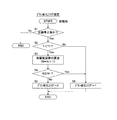
図6のフローチャートは、本発明の一実施形態に係るブラシ劣化フラグを設定するためのもので、上記他の参考例を示す図4と置き換わる。図4と同一部分には同一のステップ番号を付している。 The flowchart in FIG. 6 is for setting the brush deterioration flag according to the embodiment of the present invention, and replaces FIG. 4 showing the above-mentioned other reference example . The same steps as those in FIG. 4 are denoted by the same step numbers.
図4に示す例では、始動時のブラシ温度Tに応じて増分kを設定した。これに対し、本実施形態では、スタータ11の作動に関連する値である電圧、電流、電力、インターバルの少なくとも1つに応じて増分kを設定する。ここで、「電圧」とは1回の始動時にスタータ11に印加する電圧のことである。「電流」とは1回の始動時にスタータ11に流れる電流のことである。「電力」とは1回の始動時のスタータ11の使用電力のことである。「インターバル」とは1回の始動時にスタータ11を駆動している期間のことである。
In the example shown in FIG. 4, and sets the increment k in accordance with the brush temperature T at the start. In contrast, in the present embodiment, the voltage is a value related to the operation of the
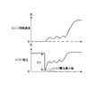
電圧、電流、電力、インターバルの少なくとも1つに応じて増分kを設定するのは、これら電圧、電流、電力、インターバルが始動時のブラシ温度(1回の始動時のブラシ摩耗量)と密接に関係しているためである。例えば、始動時にスタータ11に印加される電圧は、図7に示したように変化する。この場合に、始動前のバッテリ電圧と始動直後に生じるバッテリ電圧最小値との差電圧ΔVは、始動時のブラシ温度と相関があり、始動時のブラシ温度Tが高いほどこの差電圧ΔVが大きくなることが分かっている。従って、差電圧ΔVに対する増分kの特性を図8に示したように設定する。すなわち、差電圧に第1基準差電圧ΔV1[V]、第2基準差電圧ΔV2[V]、第3基準差電圧ΔV3[V]、第4基準差電圧ΔV4[V](ΔV1<ΔV2<ΔV3<ΔV4)を採り、差電圧ΔVが第1基準差電圧ΔV1以下(ΔV≦ΔV1)のとき増分kを1[回]とする。これは、他の参考例(図5)において始動時のブラシ温度Tが第1基準温度T1以下のときに相当する。
The increment k is set according to at least one of voltage, current, power, and interval. The voltage, current, power, and interval are closely related to the brush temperature at the start (the amount of brush wear at one start). Because it is related. For example, the voltage applied to the
一方、差電圧が第1基準差電圧温度ΔV1を超えかつ第2基準差電圧ΔV2以下(ΔV1<ΔV≦ΔV2)のとき増分kを2[回]、差電圧が第2基準差電圧ΔV2を超えかつ第3基準差電圧ΔV3以下(ΔV2<ΔV≦ΔV3)のとき増分kを3[回]、・・・としている。これは、例えば差電圧がΔV1<ΔV≦ΔV2のときには、1回の始動であってもΔV≦ΔV1のときより始動時のブラシ温度が高くて1回の始動時のブラシ摩耗量が2倍になることを意味している。従って、ΔV≦ΔV1での1回の始動時のブラシ摩耗量を基準に考えると、ΔV1<ΔV≦ΔV2のときには1回の始動で2回分の摩耗がブラシ21に生じるので、スタータの総駆動回数Nに2[回]を加算する必要があるのである。
On the other hand, when the difference voltage exceeds the first reference difference voltage temperature ΔV1 and is equal to or less than the second reference difference voltage ΔV2 (ΔV1 <ΔV ≦ ΔV2), the increment k is 2 [times], and the difference voltage exceeds the second reference difference voltage ΔV2. In addition, when the third reference difference voltage ΔV3 or less (ΔV2 <ΔV ≦ ΔV3), the increment k is set to 3 [times],. For example, when the difference voltage is ΔV1 <ΔV ≦ ΔV2, the brush temperature at the time of starting is higher than that when ΔV ≦ ΔV1 even when starting once, and the amount of brush wear at one starting is doubled. Is meant to be. Therefore, considering the amount of brush wear at the time of one start with ΔV ≦ ΔV1 as a reference, when ΔV1 <ΔV ≦ ΔV2, the wear of the
ここで、差電圧ΔVが第1基準差電圧ΔV1のときが、図5に示す例において始動時のブラシ温度Tが第1基準温度T1であるときに、差電圧ΔVが第2基準差電圧ΔV2のときが、始動時のブラシ温度Tが第2基準温度T2であるときに相当する。また、差電圧ΔVが第3基準差電圧ΔV3のときが、始動時のブラシ温度Tが第3基準温度T3であるときに、差電圧ΔVが第4基準差電圧ΔV4のときが、始動時のブラシ温度Tが第4基準温度T4であるときに相当する。 Here, when the difference voltage ΔV is the first reference difference voltage ΔV1, and in the example shown in FIG. 5, when the starting brush temperature T is the first reference temperature T1, the difference voltage ΔV is the second reference difference voltage ΔV2. time corresponds to the time the brush temperature T at the time of startup is the second reference temperature T2 of. Further, the time difference voltage ΔV is the third reference difference voltage .DELTA.V3, when the brush temperature T at the time of startup is the third reference temperature T3, a time when the differential voltage ΔV is the fourth reference difference voltage .DELTA.V4, startup This corresponds to the time when the brush temperature T is the fourth reference temperature T4.
図8では基準差電圧(ΔV1〜ΔV4)の数を4つ、増分kを1以上の整数としているが、これに限定されるものでない。基準差電圧の数は少なくとも1つあればよく、増分kは1以上の小数でもかまわない。基準差電圧の数及び増分kは最終的には適合により設定する。また、図8では増分kを不連続値で設置しているが、連続値で設定することもできる。 In FIG. 8, the number of reference difference voltages (ΔV1 to ΔV4) is four and the increment k is an integer of 1 or more, but is not limited thereto. The number of the reference difference voltages may be at least one, and the increment k may be a decimal number of 1 or more. The number of reference difference voltages and the increment k are finally set by adaptation. Further, although the increment k is set as a discontinuous value in FIG. 8, it can also be set as a continuous value.
同様にして、電流、電力、インターバルについても始動時のブラシ温度や1回の始動時のブラシ摩耗量との相関性を適合により予め求めておき、この相関性を用いて電流、電力、インターバルのいずれかと増分kとの関係を図8に示したのと同様の特性にしておき、電流、電力、インターバルのいずれかからその特性を内容とするテーブルを検索することにより増分kを設定するようにすればよい。例えば、使用した電力量により始動時のブラシ温度を予測することができる。スタータそのものの抵抗値(電圧差)を測定することにより、始動時のブラシ温度を予測することもできる。隣り合うインターバルとインターバルの間が相対的に狭いときには、隣り合うインターバルとインターバルの間が相対的に広いときより増分kを大きく設定する。また、短いインターバルが連続する場合は短いインターバルが連続しない場合より増分kを大きく設定する等が考えられる。 Similarly, for current, power, and interval, the correlation with the brush temperature at the start and the amount of brush wear at the time of one start is determined in advance, and this correlation is used to determine the current, power, and interval. The relationship between one and the increment k is set to the same characteristic as shown in FIG. 8, and the increment k is set by searching a table containing the characteristic from either current, power, or interval. do it. For example, the brush temperature at the start can be predicted from the amount of power used. By measuring the resistance value (voltage difference) of the starter itself, the brush temperature at the start can also be predicted. When the interval between adjacent intervals is relatively narrow, the increment k is set larger than when the interval between adjacent intervals is relatively wide. In addition, when the short interval continues, the increment k may be set larger than when the short interval does not continue.
図6に戻りステップ22では総駆動回数Nにこの増分kを加算した値を改めて総駆動回数Nとして、つまり上記の(2)式により総駆動回数Nを算出する。
Returning to FIG. 6, in
ステップ4では、スタータの総駆動回数Nとスタータ11の駆動保証回数N1[回]を比較し、スタータの総駆動回数Nが駆動保証回数N1未満であれば、ステップ5に進みブラシ劣化フラグ=0とする。一方、スタータの総駆動回数Nが駆動保証回数N1以上であれば、ステップ6に進みブラシ劣化フラグ=1とする。ブラシ劣化フラグ=0であるときには、エンジンの自動停止が許可され、ブラシ劣化フラグ=1であるときには、エンジンの自動停止が許可されない(エンジンの自動停止が禁止される)。In
そして、このようにして設定されるブラシ劣化フラグは、図3に例示されるのと同様のエンジン自動停止・再始動の処理において用いられる。The brush deterioration flag set in this way is used in the engine automatic stop / restart process similar to that exemplified in FIG.
本実施形態によれば、次のような作用効果を奏する。 According to this embodiment, there exist the following effects.
ブラシ21を介して給電されるスタータ11を備え、車両停止中のエンジン自動停止許可条件(第一の条件)が成立したらエンジンを自動停止し、その後に車両停車中のエンジン自動停止解除条件(第二の条件)が成立したらスタータ11を用いてエンジンを再始動させるアイドルストップ制御装置において、始動時のブラシ温度に相関する差電圧ΔV等に応じて回数相当値としての増分kを設定し、この増分kを積算した値をスタータの総始動回数Nとして算出し、このスタータの総再始動回数Nがスタータの駆動保証回数N1以上となったときブラシ劣化フラグ=1とする(エンジンの自動停止を禁止する)ことで(図6のステップ31、32、4、6参照)、ブラシ21を介して給電されるスタータ11を駆動してエンジン自動停止・再始動を行わせる場合でも、確実にエンジン自動停止・再始動を行わせることができる。本実施形態において、総駆動回数Nの増分kは、1回の始動時のブラシ摩耗量に相当し、増分kの積算値である総駆動回数Nは、総ブラシ摩耗量に相当する。A
さらに、始動時のブラシ温度Tが高いほど1回の始動時のブラシ摩耗量が大きくなることから、始動前のバッテリ電圧と始動直後に生じるバッテリ電圧最小値との差電圧ΔVが大きいときほど増分kを大きな値として設定することで、始動時のブラシ温度Tが相違しても、1回の始動時のブラシ摩耗量を精度よく推定できる。Further, the higher the brush temperature T at the time of starting, the larger the amount of brush wear at the time of starting one time. Therefore, the higher the difference voltage ΔV between the battery voltage before starting and the battery voltage minimum value immediately after starting, the higher the amount. By setting k as a large value, the brush wear amount at one start can be accurately estimated even when the brush temperature T at the start is different.
3 エンジンコントローラ
11 スタータ
21 ブラシ
31 温度センサ
3
Claims (2)
1回の始動時のブラシ摩耗量を算出する始動時ブラシ摩耗量算出手段と、
この1回の始動時のブラシ摩耗量を積算して総ブラシ摩耗量を算出する総ブラシ摩耗量算出手段と、
この総ブラシ摩耗量が前記スタータの駆動保証摩耗量以上になると、エンジンの自動停止を禁止するエンジン自動停止禁止手段と、
を備え、
前記始動時ブラシ摩耗量算出手段は、
1回の始動時にスタータへの給電によりバッテリ電圧に生じる差電圧、および、最新の始動時期とその1つ前の始動時期との間隔の少なくとも1つに基づいて、前記1回の始動時のブラシ摩耗量を推定し、
前記差電圧が大きいほど、前記1回の始動時のブラシ摩耗量が大きくなると推定し、
前記最新の始動時期とその1つ前の始動時期との間隔が狭いほど、前記1回の始動時のブラシ摩耗量が大きくなると推定する、アイドルストップ制御装置。 In an idle stop control device that automatically stops the engine when the first condition is satisfied, and restarts the engine using a starter that is fed via a brush when the second condition is satisfied,
A starting brush wear amount calculating means for calculating a brush wear amount at one start;
A total brush wear amount calculating means for calculating the total brush wear amount by integrating the brush wear amount at the time of one start;
When this total brush wear amount is equal to or greater than the drive guaranteed wear amount of the starter, engine automatic stop prohibiting means for prohibiting automatic engine stop,
With
The starting brush wear amount calculating means includes:
The brush at the time of the first start based on at least one of a differential voltage generated in the battery voltage by supplying power to the starter at the time of one start, and an interval between the latest start time and the previous start time Estimate the amount of wear ,
It is estimated that the larger the difference voltage, the greater the amount of brush wear at the time of the one start.
An idle stop control device that estimates that the amount of brush wear at the time of one start increases as the interval between the latest start time and the immediately preceding start time becomes narrower .
1回の始動時のブラシ摩耗量に応じて、何回分の始動回数に相当するかの回数相当値を設定する回数相当値設定手段と、
前記回数相当値を積算した値を、前記スタータの総再始動回数として算出する総再始動回数算出手段と、
前記スタータの総再始動回数が前記スタータの駆動保証回数以上になると、エンジンの自動停止を禁止するエンジン自動停止禁止手段と
を備え、
前記回数相当値設定手段は、
1回の始動時にスタータへの給電によりバッテリ電圧に生じる差電圧、および、最新の始動時期とその1つ前の始動時期との間隔の少なくとも1つに基づいて、前記1回の始動時のブラシ摩耗量に応じた回数相当値を設定し、
前記差電圧が大きいほど、前記回数相当値を大きな値に設定し、
前記最新の始動時期とその1つ前の始動時期との間隔が狭いほど、前記回数相当値を大きな値に設定する、アイドルストップ制御装置。 In an idle stop control device that automatically stops the engine when the first condition is satisfied, and restarts the engine using a starter that is fed via a brush when the second condition is satisfied,
A number-of-times-equivalent value setting means for setting a number-of-times-equivalent value corresponding to the number of times of start-up according to the amount of brush wear at one start-up;
A total restart number calculating means for calculating a value obtained by integrating the number corresponding to the number of times as a total restart number of the starter;
An engine automatic stop prohibiting means for prohibiting the automatic stop of the engine when the total number of restarts of the starter is equal to or greater than the guaranteed number of driving of the starter;
The number of times equivalent value setting means includes
The brush at the time of the first start based on at least one of a differential voltage generated in the battery voltage by supplying power to the starter at the time of one start, and an interval between the latest start time and the previous start time Set the number of times corresponding to the amount of wear ,
The larger the difference voltage, the larger the number of times equivalent value,
The latest starting time and smaller the interval between the start time before one that sets the number of equivalent value to a large value, the idle stop control apparatus.
Priority Applications (5)
| Application Number | Priority Date | Filing Date | Title |
|---|---|---|---|
| JP2011030469A JP6069815B2 (en) | 2011-02-16 | 2011-02-16 | Idle stop control device |
| PCT/JP2012/051498 WO2012111394A1 (en) | 2011-02-16 | 2012-01-25 | Idle stop control device |
| US13/985,777 US9502848B2 (en) | 2011-02-16 | 2012-01-25 | Idle stop control device |
| EP12747381.7A EP2677145A4 (en) | 2011-02-16 | 2012-01-25 | Idle stop control device |
| CN201280009350.3A CN103492689B (en) | 2011-02-16 | 2012-01-25 | Idle stop control device |
Applications Claiming Priority (1)
| Application Number | Priority Date | Filing Date | Title |
|---|---|---|---|
| JP2011030469A JP6069815B2 (en) | 2011-02-16 | 2011-02-16 | Idle stop control device |
Publications (2)
| Publication Number | Publication Date |
|---|---|
| JP2012167626A JP2012167626A (en) | 2012-09-06 |
| JP6069815B2 true JP6069815B2 (en) | 2017-02-01 |
Family
ID=46672332
Family Applications (1)
| Application Number | Title | Priority Date | Filing Date |
|---|---|---|---|
| JP2011030469A Expired - Fee Related JP6069815B2 (en) | 2011-02-16 | 2011-02-16 | Idle stop control device |
Country Status (5)
| Country | Link |
|---|---|
| US (1) | US9502848B2 (en) |
| EP (1) | EP2677145A4 (en) |
| JP (1) | JP6069815B2 (en) |
| CN (1) | CN103492689B (en) |
| WO (1) | WO2012111394A1 (en) |
Families Citing this family (4)
| Publication number | Priority date | Publication date | Assignee | Title |
|---|---|---|---|---|
| JP6069815B2 (en) * | 2011-02-16 | 2017-02-01 | 日産自動車株式会社 | Idle stop control device |
| JP6206218B2 (en) * | 2014-01-28 | 2017-10-04 | 株式会社デンソー | Fuel pump control device |
| US20150292465A1 (en) * | 2014-04-14 | 2015-10-15 | Ford Global Technologies, Llc | Vehicle starter activation counter |
| US10408183B2 (en) * | 2017-03-07 | 2019-09-10 | Ford Global Technologies, Llc | Methods and systems for improving engine starter durability for a stop/start vehicle |
Family Cites Families (26)
| Publication number | Priority date | Publication date | Assignee | Title |
|---|---|---|---|---|
| US3612928A (en) * | 1970-03-19 | 1971-10-12 | Charles B Small | Submerged dc motor |
| US4334188A (en) * | 1980-02-06 | 1982-06-08 | Eltra Corporation | Voltage detector using an oscillator and comparator means |
| US4316186A (en) * | 1980-02-06 | 1982-02-16 | Eltra Corporation | Brush wear detection and warning system |
| JPS62155744A (en) * | 1985-11-21 | 1987-07-10 | Mitsubishi Electric Corp | Controller for abrasion of brush for servomotor |
| JPS62155745A (en) * | 1985-11-21 | 1987-07-10 | Mitsubishi Electric Corp | Controller for abrasion of brush for servomotor |
| JPH06141513A (en) * | 1992-07-22 | 1994-05-20 | Toyoda Mach Works Ltd | Brush monitor of rotating motor |
| JP3042396B2 (en) * | 1995-06-27 | 2000-05-15 | 株式会社デンソー | Rotating electric machine |
| JP3928828B2 (en) * | 1998-06-24 | 2007-06-13 | 本田技研工業株式会社 | Engine start and assist device |
| JP2001065440A (en) * | 1999-08-23 | 2001-03-16 | Denso Corp | Vehicular electronic conrol device |
| JP4424573B2 (en) * | 2000-10-03 | 2010-03-03 | 本田技研工業株式会社 | Engine automatic stop / start control device |
| US20060200292A1 (en) * | 2003-01-31 | 2006-09-07 | Obelco Construction Machinery Co., Ltd. | Engine control device for and administration system for contruction machine |
| JP4512318B2 (en) * | 2003-02-04 | 2010-07-28 | 日立化成工業株式会社 | Laminated brush |
| JP4493324B2 (en) * | 2003-12-03 | 2010-06-30 | 三菱電機株式会社 | Brush generator detection device for vehicular generator |
| JP4380393B2 (en) | 2004-03-31 | 2009-12-09 | トヨタ自動車株式会社 | Brush state judgment device for motor |
| DE102005060324B4 (en) * | 2005-12-16 | 2021-03-18 | Robert Bosch Gmbh | Detection of the wear of a motor control |
| DE202006019888U1 (en) * | 2006-02-28 | 2007-05-16 | Gefeg-Neckar Antriebssysteme Gmbh | Electric motor e.g. repulsion motor, has mechanical commutation system, and integrated operating electronics that comprises wear indicator for evaluating wear level of commutation system based on operating hours |
| JP4488238B2 (en) * | 2006-03-28 | 2010-06-23 | 株式会社デンソー | Fuel pump drive control device |
| DE102007024352A1 (en) * | 2007-05-24 | 2008-11-27 | Ford Global Technologies, LLC, Dearborn | Method for operating motor vehicle system, executing function of motor vehicle system in repeated manner during operation of vehicle, where wear of motor vehicle influencing variables are determined |
| JP2008291756A (en) * | 2007-05-25 | 2008-12-04 | Denso Corp | Fuel pump failure diagnosis device |
| JP4855337B2 (en) * | 2007-05-29 | 2012-01-18 | 新明和工業株式会社 | Fluid pressure device with brush wear detection device |
| EP2176946A2 (en) * | 2007-07-12 | 2010-04-21 | Robert Bosch GmbH | Starter device |
| JP2011020567A (en) * | 2009-07-16 | 2011-02-03 | Toyota Motor Corp | Shock absorber |
| JP2011062020A (en) * | 2009-09-11 | 2011-03-24 | Advics Co Ltd | Dc motor management device |
| FR2961973B1 (en) * | 2010-06-25 | 2012-07-13 | Valeo Equip Electr Moteur | METHOD FOR DETECTING BRAKE WEAR FOR ALTERNOMETER IN A VEHICLE |
| WO2012077227A1 (en) * | 2010-12-10 | 2012-06-14 | 三菱電機株式会社 | Rotating electrical machine |
| JP6069815B2 (en) * | 2011-02-16 | 2017-02-01 | 日産自動車株式会社 | Idle stop control device |
-
2011
- 2011-02-16 JP JP2011030469A patent/JP6069815B2/en not_active Expired - Fee Related
-
2012
- 2012-01-25 CN CN201280009350.3A patent/CN103492689B/en not_active Expired - Fee Related
- 2012-01-25 WO PCT/JP2012/051498 patent/WO2012111394A1/en active Application Filing
- 2012-01-25 EP EP12747381.7A patent/EP2677145A4/en not_active Withdrawn
- 2012-01-25 US US13/985,777 patent/US9502848B2/en not_active Expired - Fee Related
Also Published As
| Publication number | Publication date |
|---|---|
| US20130338908A1 (en) | 2013-12-19 |
| WO2012111394A1 (en) | 2012-08-23 |
| CN103492689A (en) | 2014-01-01 |
| CN103492689B (en) | 2017-04-12 |
| US9502848B2 (en) | 2016-11-22 |
| JP2012167626A (en) | 2012-09-06 |
| EP2677145A1 (en) | 2013-12-25 |
| EP2677145A4 (en) | 2018-08-15 |
Similar Documents
| Publication | Publication Date | Title |
|---|---|---|
| US20100256896A1 (en) | Engine starting device for idling-stop vehicle | |
| CN105083260B (en) | Controller of vehicle, vehicle and control method for vehicle | |
| EP2221226A1 (en) | Idle stop control apparatus and method thereof | |
| JP5428931B2 (en) | Starter control device | |
| JP6069815B2 (en) | Idle stop control device | |
| JP5212391B2 (en) | Idle stop control device | |
| RU2016116004A (en) | START-UP MANAGEMENT DEVICE AND START-UP MANAGEMENT METHOD FOR HYBRID VEHICLE | |
| JP5470241B2 (en) | Vehicle control device | |
| JP5811574B2 (en) | Start control device for variable compression ratio engine | |
| US20140350827A1 (en) | Restarting device of internal combustion engine | |
| JP4937374B2 (en) | Start control device | |
| JP2012184703A (en) | Engine stop/start control system | |
| JP5966306B2 (en) | Parallel hybrid vehicle control method and parallel hybrid vehicle control apparatus | |
| JP2009527692A (en) | Method and system for preheating a diesel engine air / fuel mixture by controlling a low voltage discharging plug | |
| JP2014152676A (en) | Control device of internal combustion engine | |
| JP2010112354A (en) | Controller of vehicle internal combustion engine | |
| JP2013053578A (en) | Idle stop control device | |
| JP5353422B2 (en) | Vehicle power generation control device | |
| JP2010185425A (en) | Control device of internal combustion engine | |
| JP5999930B2 (en) | Engine control device | |
| JP5678722B2 (en) | Oil temperature estimation device | |
| JP7017350B2 (en) | Battery fluid temperature estimator | |
| JP5894048B2 (en) | Diesel engine with electronic governor | |
| CN114729618A (en) | Management method for managing the torque drawn by an alternator from a heat engine | |
| KR20130060567A (en) | Vehicle generating system for cold start, and control method of the same |
Legal Events
| Date | Code | Title | Description |
|---|---|---|---|
| A621 | Written request for application examination |
Free format text: JAPANESE INTERMEDIATE CODE: A621 Effective date: 20131224 |
|
| A131 | Notification of reasons for refusal |
Free format text: JAPANESE INTERMEDIATE CODE: A131 Effective date: 20150120 |
|
| A131 | Notification of reasons for refusal |
Free format text: JAPANESE INTERMEDIATE CODE: A131 Effective date: 20150811 |
|
| A521 | Request for written amendment filed |
Free format text: JAPANESE INTERMEDIATE CODE: A523 Effective date: 20151006 |
|
| A131 | Notification of reasons for refusal |
Free format text: JAPANESE INTERMEDIATE CODE: A131 Effective date: 20160308 |
|
| A521 | Request for written amendment filed |
Free format text: JAPANESE INTERMEDIATE CODE: A523 Effective date: 20160502 |
|
| A131 | Notification of reasons for refusal |
Free format text: JAPANESE INTERMEDIATE CODE: A131 Effective date: 20161004 |
|
| A521 | Request for written amendment filed |
Free format text: JAPANESE INTERMEDIATE CODE: A523 Effective date: 20161028 |
|
| TRDD | Decision of grant or rejection written | ||
| RD02 | Notification of acceptance of power of attorney |
Free format text: JAPANESE INTERMEDIATE CODE: A7422 Effective date: 20161205 |
|
| A01 | Written decision to grant a patent or to grant a registration (utility model) |
Free format text: JAPANESE INTERMEDIATE CODE: A01 Effective date: 20161206 |
|
| A61 | First payment of annual fees (during grant procedure) |
Free format text: JAPANESE INTERMEDIATE CODE: A61 Effective date: 20161219 |
|
| R151 | Written notification of patent or utility model registration |
Ref document number: 6069815 Country of ref document: JP Free format text: JAPANESE INTERMEDIATE CODE: R151 |
|
| LAPS | Cancellation because of no payment of annual fees |