JP6068751B2 - Operation pedal device for vehicle - Google Patents
Operation pedal device for vehicle Download PDFInfo
- Publication number
- JP6068751B2 JP6068751B2 JP2013227905A JP2013227905A JP6068751B2 JP 6068751 B2 JP6068751 B2 JP 6068751B2 JP 2013227905 A JP2013227905 A JP 2013227905A JP 2013227905 A JP2013227905 A JP 2013227905A JP 6068751 B2 JP6068751 B2 JP 6068751B2
- Authority
- JP
- Japan
- Prior art keywords
- pedal
- operation amount
- amount sensor
- wall portion
- vehicle
- Prior art date
- Legal status (The legal status is an assumption and is not a legal conclusion. Google has not performed a legal analysis and makes no representation as to the accuracy of the status listed.)
- Active
Links
Images


Classifications
-
- G—PHYSICS
- G05—CONTROLLING; REGULATING
- G05G—CONTROL DEVICES OR SYSTEMS INSOFAR AS CHARACTERISED BY MECHANICAL FEATURES ONLY
- G05G1/00—Controlling members, e.g. knobs or handles; Assemblies or arrangements thereof; Indicating position of controlling members
- G05G1/30—Controlling members actuated by foot
- G05G1/38—Controlling members actuated by foot comprising means to continuously detect pedal position
-
- B—PERFORMING OPERATIONS; TRANSPORTING
- B60—VEHICLES IN GENERAL
- B60K—ARRANGEMENT OR MOUNTING OF PROPULSION UNITS OR OF TRANSMISSIONS IN VEHICLES; ARRANGEMENT OR MOUNTING OF PLURAL DIVERSE PRIME-MOVERS IN VEHICLES; AUXILIARY DRIVES FOR VEHICLES; INSTRUMENTATION OR DASHBOARDS FOR VEHICLES; ARRANGEMENTS IN CONNECTION WITH COOLING, AIR INTAKE, GAS EXHAUST OR FUEL SUPPLY OF PROPULSION UNITS IN VEHICLES
- B60K26/00—Arrangements or mounting of propulsion unit control devices in vehicles
- B60K26/02—Arrangements or mounting of propulsion unit control devices in vehicles of initiating means or elements
-
- B—PERFORMING OPERATIONS; TRANSPORTING
- B60—VEHICLES IN GENERAL
- B60K—ARRANGEMENT OR MOUNTING OF PROPULSION UNITS OR OF TRANSMISSIONS IN VEHICLES; ARRANGEMENT OR MOUNTING OF PLURAL DIVERSE PRIME-MOVERS IN VEHICLES; AUXILIARY DRIVES FOR VEHICLES; INSTRUMENTATION OR DASHBOARDS FOR VEHICLES; ARRANGEMENTS IN CONNECTION WITH COOLING, AIR INTAKE, GAS EXHAUST OR FUEL SUPPLY OF PROPULSION UNITS IN VEHICLES
- B60K26/00—Arrangements or mounting of propulsion unit control devices in vehicles
- B60K26/04—Arrangements or mounting of propulsion unit control devices in vehicles of means connecting initiating means or elements to propulsion unit
-
- B—PERFORMING OPERATIONS; TRANSPORTING
- B60—VEHICLES IN GENERAL
- B60T—VEHICLE BRAKE CONTROL SYSTEMS OR PARTS THEREOF; BRAKE CONTROL SYSTEMS OR PARTS THEREOF, IN GENERAL; ARRANGEMENT OF BRAKING ELEMENTS ON VEHICLES IN GENERAL; PORTABLE DEVICES FOR PREVENTING UNWANTED MOVEMENT OF VEHICLES; VEHICLE MODIFICATIONS TO FACILITATE COOLING OF BRAKES
- B60T7/00—Brake-action initiating means
- B60T7/02—Brake-action initiating means for personal initiation
- B60T7/04—Brake-action initiating means for personal initiation foot actuated
- B60T7/042—Brake-action initiating means for personal initiation foot actuated by electrical means, e.g. using travel or force sensors
-
- G—PHYSICS
- G05—CONTROLLING; REGULATING
- G05G—CONTROL DEVICES OR SYSTEMS INSOFAR AS CHARACTERISED BY MECHANICAL FEATURES ONLY
- G05G1/00—Controlling members, e.g. knobs or handles; Assemblies or arrangements thereof; Indicating position of controlling members
- G05G1/30—Controlling members actuated by foot
- G05G1/44—Controlling members actuated by foot pivoting
Landscapes
- Engineering & Computer Science (AREA)
- Transportation (AREA)
- Mechanical Engineering (AREA)
- Physics & Mathematics (AREA)
- General Physics & Mathematics (AREA)
- Automation & Control Theory (AREA)
- Chemical & Material Sciences (AREA)
- Combustion & Propulsion (AREA)
- Mechanical Control Devices (AREA)
- Braking Elements And Transmission Devices (AREA)
Description
本発明は車両用操作ペダル装置に係り、特に、ペダルブラケットに操作量センサが配設されている車両用操作ペダル装置の改良に関するものである。 The present invention relates to a vehicle operation pedal device, and more particularly to an improvement in a vehicle operation pedal device in which an operation amount sensor is disposed on a pedal bracket.
(a) 車両に取り付けられるペダルブラケットと、(b) そのペダルブラケットに略水平な支持軸心まわりに揺動自在に支持されるとともに、そのペダルブラケットから下方へ延び出し、下端部に設けられた踏部が足踏み操作されるペダルアームと、(c) 前記ペダルブラケットに配設されて前記ペダルアームの操作量を検出する操作量センサと、を有する車両用操作ペダル装置が知られている(特許文献1参照)。 (a) a pedal bracket attached to the vehicle, and (b) supported by the pedal bracket so as to be swingable about a substantially horizontal support axis, extending downward from the pedal bracket, and provided at the lower end. There is known a vehicular operating pedal device having a pedal arm on which a stepping part is operated, and (c) an operation amount sensor that is disposed on the pedal bracket and detects an operation amount of the pedal arm (patent) Reference 1).
しかしながら、上記操作量センサは一般に運転者の足が届く範囲に配置されているため、蹴り上げにより操作量センサが変形したり損傷したりする恐れがあった。これに対し、未だ公知ではないが、例えば特許文献2に記載の技術、すなわち運転者の足とリターンスプリングとの接触を抑制する遮蔽部を設ける技術、を適用して操作量センサを保護するカバー部材をペダルアーム或いはペダルブラケットに設けることが考えられる。しかし、十分な強度を確保する上で金属製のカバー部材を採用すると、重量が大幅に増加する。金属の場合、操作量センサの形状に合わせて成形することが難しいため、操作量センサに比べてカバー部材が必要以上に大きくなり、それに伴って重量が大幅に増加してしまうのである。
However, since the operation amount sensor is generally disposed in a range that can be reached by the driver's foot, the operation amount sensor may be deformed or damaged by kicking up. On the other hand, although not yet known, for example, a cover that protects the operation amount sensor by applying the technique described in
本発明は以上の事情を背景として為されたもので、その目的とするところは、操作量センサが配置された車両用操作ペダル装置において、重量増加を抑制しつつ蹴り上げによる操作量センサの損傷を適切に防止することにある。 The present invention has been made against the background of the above circumstances. The object of the present invention is to damage the operation amount sensor due to kicking while suppressing an increase in weight in a vehicle operation pedal device in which the operation amount sensor is arranged. It is to prevent appropriately.
かかる目的を達成するために、第1発明は、(a) 車両に取り付けられるペダルブラケットと、(b) そのペダルブラケットに略水平な支持軸心まわりに揺動自在に支持されるとともに、そのペダルブラケットから下方へ延び出し、下端部に設けられた踏部が足踏み操作されるペダルアームと、(c) 前記ペダルブラケットに配設されて前記ペダルアームの操作量を検出する操作量センサと、を有する車両用操作ペダル装置において、(d) 前記操作量センサの下側から運転席側に位置する下方壁部を少なくとも備えており、前記ペダルブラケットに一体的に取り付けられたカバー部材と、(e) 前記ペダルアームが足踏み操作されていない初期状態において、前記下方壁部と前記操作量センサとの間に介在させられるように、前記ペダルアームに一体的に固定された金属製の補強部材と、を有することを特徴とする。 In order to achieve such an object, the first invention includes: (a) a pedal bracket attached to a vehicle; and (b) a pedal bracket that is swingably supported around a substantially horizontal support axis, and the pedal. A pedal arm that extends downward from the bracket, and a stepped portion provided at the lower end is operated to be stepped on; and (c) an operation amount sensor that is disposed on the pedal bracket and detects an operation amount of the pedal arm. (D) a cover member that is at least provided with a lower wall portion that is positioned from the lower side of the operation amount sensor to the driver's seat side, and is integrally attached to the pedal bracket; ) In an initial state where the pedal arm is not stepped on, the pedal arm is integrally fixed so as to be interposed between the lower wall portion and the operation amount sensor. And having a metal reinforcing member that is, a.
第2発明は、第1発明の車両用操作ペダル装置において、前記カバー部材は、前記下方壁部から連続して前記操作量センサの外側を上方へ延びるように設けられた側方壁部と、その側方壁部から連続してその操作量センサの上側に位置するように設けられた上方壁部とを一体に備えている合成樹脂製の部材で、その操作量センサの下方、側方、および上方を覆蓋していることを特徴とする。 According to a second aspect of the present invention, in the vehicle operation pedal device according to the first aspect of the invention, the cover member includes a side wall provided so as to continuously extend outward from the operation amount sensor from the lower wall. A synthetic resin member integrally provided with an upper wall provided so as to be positioned above the operation amount sensor continuously from the side wall portion, below the operation amount sensor, on the side, And the upper part is covered, It is characterized by the above-mentioned.
第3発明は、第2発明の車両用操作ペダル装置において、(a) 前記カバー部材には、運転席と反対の前記操作量センサの後方側にも、前記ペダルアームの揺動に伴う前記補強部材の移動を阻害しないように後方壁部が設けられており、且つ、(b) 前記下方壁部と前記側方壁部とを繋ぐコーナー部分の内面側には補強リブが設けられていることを特徴とする。 According to a third aspect of the present invention, in the vehicle operation pedal device according to the second aspect of the invention, (a) the cover member is provided with the reinforcement accompanying the swing of the pedal arm also on the rear side of the operation amount sensor opposite to the driver's seat. A rear wall portion is provided so as not to hinder the movement of the member, and (b) a reinforcing rib is provided on the inner surface side of the corner portion connecting the lower wall portion and the side wall portion. It is characterized by.
このような車両用操作ペダル装置においては、少なくとも操作量センサの下方を保護するカバー部材がペダルブラケットに取り付けられているとともに、ペダルアームに固定された補強部材がそのカバー部材の下方壁部と操作量センサとの間に介在させられるようになっているため、足の蹴り上げによる操作量センサの損傷がカバー部材によって適切に防止される。カバー部材は補強部材によって過度の変形が防止されるため、例えば合成樹脂等を用いて軽量で且つ安価に構成することができる一方、補強部材はカバー部材の破損や変形を防止できるように蹴り上げ方向等を考慮して必要最小限の範囲に設けられれば良いため、所定の強度を確保しつつ全体として軽量で且つ安価に構成することができる。 In such a vehicle operation pedal device, a cover member that protects at least the lower part of the operation amount sensor is attached to the pedal bracket, and a reinforcing member fixed to the pedal arm operates with the lower wall portion of the cover member. Since it is interposed between the sensor and the amount sensor, damage to the operation amount sensor due to kicking of the foot is appropriately prevented by the cover member. Since the cover member is prevented from being excessively deformed by the reinforcing member, the cover member can be configured to be lightweight and inexpensive using, for example, a synthetic resin, while the reinforcing member is kicked up to prevent the cover member from being damaged or deformed. Since it suffices if it is provided within the minimum necessary range in consideration of the direction and the like, it is possible to construct a light weight and low cost as a whole while ensuring a predetermined strength.
第2発明では、上記カバー部材が合成樹脂製で、下方壁部の他に側方壁部および上方壁部を一体に備えており、操作量センサの下方、側方、および上方を覆蓋するようになっているため、足の蹴り上げだけでなく、蹴り上げ以外の動作による足との接触や、埃や水等からも操作量センサが適切に保護される。また、合成樹脂製であるため成形の自由度が高く、ペダルブラケットの多様な形状や操作量センサの様々な配置位置、形状等に対しても、操作量センサを適切に保護できるように容易に対応できる。 In the second invention, the cover member is made of synthetic resin, and integrally includes a side wall portion and an upper wall portion in addition to the lower wall portion so as to cover the lower side, the side, and the upper side of the operation amount sensor. Therefore, the operation amount sensor is appropriately protected not only from kicking up the foot, but also from contact with the foot due to operations other than kicking up, dust, water, and the like. In addition, because it is made of synthetic resin, the degree of freedom of molding is high, and it is easy to protect the operation amount sensor appropriately against various shapes of pedal brackets and various arrangement positions and shapes of operation amount sensors. Yes.
第3発明では、ペダルアームの揺動に伴う補強部材の移動を阻害しないように後方壁部が設けられているため、操作量センサが一層適切に保護されるとともに、下方壁部と側方壁部とのコーナー部分には補強リブが設けられているため、カバー部材の剛性が高くなり、必要強度を確保しつつ薄肉化や補強部材の小型化により一層の軽量化を図ることができる。 In the third aspect of the invention, since the rear wall portion is provided so as not to hinder the movement of the reinforcing member accompanying the swing of the pedal arm, the operation amount sensor is more appropriately protected, and the lower wall portion and the side wall are protected. Since the reinforcing rib is provided at the corner portion with the portion, the rigidity of the cover member is increased, and further weight reduction can be achieved by reducing the thickness or reducing the size of the reinforcing member while ensuring the required strength.
本発明は、常用ブレーキ用の操作ペダル装置に好適に適用されるが、アクセル用やパーキングブレーキ用等の他の操作ペダル装置に適用することもできる。また、ペダルアームにオペレーティングロッド等の出力部材が直接連結されている場合だけでなく、連結リンクを介して中間レバーが連結されている場合や、出力部材の代わりに反力付与装置が連結されている場合にも適用され得る。 The present invention is preferably applied to an operation pedal device for a service brake, but can also be applied to other operation pedal devices such as an accelerator and a parking brake. Moreover, not only when an output member such as an operating rod is directly connected to the pedal arm, but also when an intermediate lever is connected via a connecting link, or a reaction force applying device is connected instead of the output member. It can also be applied to
ペダルブラケットは、例えばペダルアームの左右両側に位置する一対の側板を有して構成され、その一対の側板に跨がって配設された支持軸によりペダルアームが揺動可能に支持されるとともに、一方の側板の外側に操作量センサが配設される。操作量センサは、例えばペダルアームの揺動ストロークや揺動角度を検出するように構成されるが、踏込み操作力や伝達荷重等を検出するものでも良い。 For example, the pedal bracket includes a pair of side plates positioned on both the left and right sides of the pedal arm, and the pedal arm is swingably supported by a support shaft disposed across the pair of side plates. An operation amount sensor is disposed outside the one side plate. The operation amount sensor is configured to detect, for example, a swing stroke or a swing angle of the pedal arm, but may detect a stepping operation force, a transmission load, or the like.
カバー部材は、軽量な合成樹脂材料にて構成することが望ましいが、成形が容易で軽量なアルミニウム等の金属材料など他の材料を用いることも可能である。このカバー部材は、例えば合成樹脂製の差込みクリップなどでワンタッチで取り付けることもできるし、ボルト等のねじ締結でペダルブラケットに取り付けるものでも良い。補強部材は、例えば鉄等の金属板材にて構成されるとともに、その金属板材をL字形状等に折り曲げただけのものが好適に用いられる。そして、L字形状に折り曲げられた一対の平板部の何れか一方が、カバー部材の下方壁部と操作量センサとの間に挿入されるように、例えばL字型の側端縁が溶接等によりペダルアームの側面等に一体的に固設される。一対の平板部の他方をペダルアームの側面と平行に密着させて溶接などで固設するようにしても良い。 The cover member is preferably made of a lightweight synthetic resin material, but it is also possible to use other materials such as a metal material such as aluminum that is easy to mold and lightweight. This cover member can be attached with a one-touch with, for example, a synthetic resin insertion clip, or may be attached to the pedal bracket by screw fastening such as a bolt. As the reinforcing member, for example, a metal plate material such as iron, and a member obtained by bending the metal plate material into an L shape or the like is preferably used. Then, for example, the L-shaped side edge is welded or the like so that either one of the pair of flat plates bent into an L shape is inserted between the lower wall portion of the cover member and the operation amount sensor. Is integrally fixed to the side surface of the pedal arm. The other of the pair of flat plate portions may be attached in parallel with the side surface of the pedal arm and fixed by welding or the like.
以下、本発明の実施例を、図面を参照しつつ詳細に説明する。
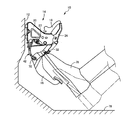
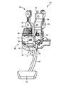
図1は、本発明の一実施例である車両の常用ブレーキ用の操作ペダル装置10を示す図で、車両のダッシュパネル12に配設された状態の左側面図である。図2は、車両用操作ペダル装置10のみを拡大して示した左側面で、図3は運転席側から見た正面図、図4は運転席側の斜め左上方向から見た斜視図、図5は運転席と反対の車両前側の斜め右上方向から見た斜視図、図6は車両前側から見た背面図である。この車両用操作ペダル装置10は、ダッシュパネル12に一体的に固設されるペダルブラケット14と、運転者よって足踏み操作されるペダルアーム16と、そのペダルアーム16に連結リンクを介して作動的に連結された中間レバー18とを備えており、その中間レバー18にブレーキブースタのオペレーティングロッド等が連結される。
Hereinafter, embodiments of the present invention will be described in detail with reference to the drawings.
FIG. 1 is a diagram showing an
ペダルブラケット14は、左右一対の側板部材20、22と、それ等の側板部材20、22の先端側(運転席側)を連結するように一体的に固設された先端連結部材24とを有し、側板部材20、22に跨がって略水平に配設された支持軸26の軸心(支持軸心)Oまわりに揺動可能にペダルアーム16が支持されている。一対の側板部材20、22は、運転席と反対側すなわちダッシュパネル12側においても、後側連結プレート28を介して一体的に連結されている。支持軸26は、図6に示されるように一対の側板部材20、22、およびそれ等の間に配設されたペダルアーム16を貫通するように設けられたボルトである。ペダルアーム16はペダルブラケット14から下方へ延び出しており、その下端部に設けられた踏部30が運転者によって足踏み操作されるとともに、ペダルアーム16と先端連結部材24とに跨がって配設されたリターンスプリング32によって図1〜図6の各図に示す初期位置へ戻されるようになっている。側板部材20、22は、それ等の間でペダルアーム16を揺動可能に支持している一対の側板として機能している。
The
ペダルブラケット14の一方の側板部材20の外側、すなわち左側の側板部材20の左側の側面には、操作量センサとしてストロークセンサ40が配設され、ペダルアーム16の揺動ストロークを検出するようになっているとともに、そのストロークセンサ40を覆蓋するようにカバー部材42が一体的に取り付けられている。図2では、カバー部材42を破線で示し、内部のストロークセンサ40等を実線で示してある。図7は、カバー部材42を単独で示す図で、4方向から見た四面図であり、(a) は正面図、(b) は左側面図、(c) は右側面図、(d) は平面図である。(a) の正面図は、図3の正面図に対応する。このカバー部材42は合成樹脂材料にて一体成形されたもので、ストロークセンサ40の下側から運転席側に位置するように運転席側へ向かうに従って上方へ傾斜する下方壁部44と、その下方壁部44から連続してストロークセンサ40の外側を上方へ延びるように設けられた側方壁部46と、下方壁部44の前端部および側方壁部46から連続してストロークセンサ40の上側に位置するように設けられた上方壁部48とを一体に備えており、ストロークセンサ40の下方、側方、および上方を覆蓋するようになっている。上方壁部48には、ストロークセンサ40に連結されるワイヤハーネスを通すための切欠49が設けられている。
A
上方壁部48の後端部には略垂直に立ち上がる取付壁部50が設けられているとともに、その取付壁部50および下方壁部44の前端部分にはそれぞれ取付穴52、54が設けられており、取付穴54側については合成樹脂製の差込みクリップ56(図3参照)を差し込むだけでワンタッチで側板部材20に取り付けることができる。他方の取付穴52側については、所定の取付強度を確保するためにボルトおよびナット等のねじ部材57(図3、図4等参照)によって側板部材20に取り付けられるようになっている。側板部材20には、取付穴52、54に対応して挿通穴が設けられており、差込みクリップ56やねじ部材57のボルト等が挿通させられるようになっている。
A mounting
また、運転席と反対のストロークセンサ40の後方側には、側方壁部46の上端部と取付壁部50とを連結するように三角形状の後方壁部60が設けられている。また、下方壁部44と側方壁部46とを繋ぐコーナー部分の内面側には複数の補強リブ62が設けられており、側方壁部46と上方壁部48乃至は取付壁部50とを繋ぐコーナー部分の内側には複数の補強リブ64が設けられている。
Further, a triangular
一方、ペダルアーム16の左側面には金属製の補強部材70が溶接等により一体的に固設されており、ペダルアーム16が足踏み操作されていない初期状態において、下方壁部44の後端部分とストロークセンサ40との間に、その補強部材70が介在させられるようになっている。補強部材70は、図8に示すように鉄等の金属板材を略L字形状に折り曲げたもので、一対の平板部72、74を備えており、L字型の側端縁がペダルアーム16の左側面に密着して一体的に固設されている。図8は、図5に対応する斜視図である。そして、ペダルアーム16がリターンスプリング32の付勢力に従って初期位置まで戻されると、平板部74が下方壁部44と略平行になる姿勢で、その下方壁部44とストロークセンサ40との間に挿入され、それ等の間に介在させられるようになっている。これにより、図1に実線で示すように運転者の足76でカバー部材42が蹴り上げられた際に、下方壁部44が平板部74に当接することにより過度の変形が阻止され、カバー部材42の変形や破損が防止されてストロークセンサ40を適切に保護することができる。図1の一点鎖線で示す足76は、アクセル操作等をしている際の通常のポジションで、床78上に置かれているが、ブレーキ操作する際に足76を持ち上げる時などに、ストロークセンサ40を蹴り上げる可能性がある。
On the other hand, a
平板部74と下方壁部44との間の隙間a(図2参照)は、ペダルアーム16の揺動時の干渉を回避しつつカバー部材42の過度の変形を阻止し、塑性変形や破損を防止できるように適宜定められ、本実施例では5mm程度の寸法に設定されている。カバー部材42と平板部74との重なり寸法b(図3参照)についても、カバー部材42の塑性変形や破損を防止できるように適宜定められ、本実施例では補強リブ62が設けられていることから、その補強リブ62を除いた範囲を補強できれば良く、例えば下方壁部44の全幅寸法cの1/3〜1/2程度で良い。
The gap a (see FIG. 2) between the
前記後方壁部60は、カバー部材42の上端部に設けられているだけで、補強部材70と干渉する恐れは無い。カバー部材42の後方は大きく開口しているが、ダッシュパネル12に近接しているため、後方から外力が加えられてストロークセンサ40が損傷する可能性は小さい。
The
このように、本実施例の車両用操作ペダル装置10においては、ペダルブラケット14に配設されたストロークセンサ40を覆蓋するようにカバー部材42がペダルブラケット14に取り付けられているとともに、ペダルアーム16に固定された補強部材70がそのカバー部材42の下方壁部44とストロークセンサ40との間に介在させられるようになっているため、足76の蹴り上げによるストロークセンサ40の損傷がカバー部材42によって適切に防止される。カバー部材42は補強部材70によって過度の変形が防止されるため、合成樹脂材料を用いて軽量で且つ安価に構成することができる一方、補強部材70はカバー部材42の破損や変形を防止できるように蹴り上げ方向等を考慮して必要最小限の範囲に設けられれば良いため、所定の強度を確保しつつ全体として軽量で且つ安価に構成することができる。
Thus, in the vehicle
また、カバー部材42が合成樹脂製で、下方壁部44の他に側方壁部46、上方壁部48、および後方壁部60を一体に備えており、ストロークセンサ40の下方、側方、上方、および後部上方を覆蓋するようになっているため、足76の蹴り上げだけでなく、蹴り上げ以外の動作による足76との接触や、埃や水等からもストロークセンサ40が適切に保護される。特に、合成樹脂製であるため成形の自由度が高く、ペダルブラケット14の多様な形状やストロークセンサ40の様々な配置位置、形状等に対しても、ストロークセンサ40を適切に保護できるように容易に対応できる。
Further, the
また、ペダルアーム16の揺動に伴う補強部材70の移動を阻害しないように後方壁部60が設けられているため、ストロークセンサ40が一層適切に保護されるとともに、下方壁部44と側方壁部46とのコーナー部分、側方壁部46と上方壁部48乃至は取付壁部50とのコーナー部分には、それぞれ補強リブ62、64が設けられているため、カバー部材42の剛性が高くなり、必要強度を確保しつつ薄肉化や補強部材70の小型化により一層の軽量化を図ることができる。
Further, since the
以上、本発明の実施例を図面に基づいて詳細に説明したが、これはあくまでも一実施形態であり、本発明は当業者の知識に基づいて種々の変更、改良を加えた態様で実施することができる。 As mentioned above, although the Example of this invention was described in detail based on drawing, this is an embodiment to the last, and this invention is implemented in the aspect which added various change and improvement based on the knowledge of those skilled in the art. Can do.
10:車両用操作ペダル装置 14:ペダルブラケット 16:ペダルアーム 40:ストロークセンサ(操作量センサ) 42:カバー部材 44:下方壁部 46:側方壁部 48:上方壁部 60:後方壁部 62:補強リブ 70:補強部材 O:軸心(支持軸心) 10: Vehicle operation pedal device 14: Pedal bracket 16: Pedal arm 40: Stroke sensor (operation amount sensor) 42: Cover member 44: Lower wall portion 46: Side wall portion 48: Upper wall portion 60: Rear wall portion 62 : Reinforcement rib 70: Reinforcement member O: Axle (support axis)
Claims (3)
該ペダルブラケットに略水平な支持軸心まわりに揺動自在に支持されるとともに、該ペダルブラケットから下方へ延び出し、下端部に設けられた踏部が足踏み操作されるペダルアームと、
前記ペダルブラケットに配設されて前記ペダルアームの操作量を検出する操作量センサと、
を有する車両用操作ペダル装置において、
前記操作量センサの下側から運転席側に位置する下方壁部を少なくとも備えており、前記ペダルブラケットに一体的に取り付けられたカバー部材と、
前記ペダルアームが足踏み操作されていない初期状態において、前記下方壁部と前記操作量センサとの間に介在させられるように、前記ペダルアームに一体的に固定された金属製の補強部材と、
を有することを特徴とする車両用操作ペダル装置。 A pedal bracket attached to the vehicle;
A pedal arm that is supported by the pedal bracket so as to be swingable about a substantially horizontal support axis, extends downward from the pedal bracket, and a stepped portion provided at a lower end is operated to be stepped on;
An operation amount sensor disposed on the pedal bracket for detecting an operation amount of the pedal arm;
In a vehicle operation pedal device having
A cover member attached at least to the pedal bracket, comprising at least a lower wall portion located on the driver's seat side from the lower side of the operation amount sensor;
In an initial state where the pedal arm is not stepped on, a metal reinforcing member integrally fixed to the pedal arm so as to be interposed between the lower wall portion and the operation amount sensor;
An operation pedal device for a vehicle characterized by comprising:
ことを特徴とする請求項1に記載の車両用操作ペダル装置。 The cover member includes a side wall provided so as to continuously extend from the lower wall to the outside of the operation amount sensor, and an upper side of the operation amount sensor continuously from the side wall. A synthetic resin member integrally provided with an upper wall portion provided so as to be positioned, and covers a lower portion, a side portion, and an upper portion of the operation amount sensor. The vehicle operating pedal device according to the description.
且つ、前記下方壁部と前記側方壁部とを繋ぐコーナー部分の内面側には補強リブが設けられている
ことを特徴とする請求項2に記載の車両用操作ペダル装置。 The cover member is provided with a rear wall portion on the rear side of the operation amount sensor opposite to the driver's seat so as not to hinder the movement of the reinforcing member accompanying the swing of the pedal arm,
And the reinforcing rib is provided in the inner surface side of the corner part which connects the said lower wall part and the said side wall part. The vehicle operation pedal apparatus of Claim 2 characterized by the above-mentioned.
Priority Applications (5)
| Application Number | Priority Date | Filing Date | Title |
|---|---|---|---|
| JP2013227905A JP6068751B2 (en) | 2013-11-01 | 2013-11-01 | Operation pedal device for vehicle |
| PCT/JP2014/068831 WO2015064156A1 (en) | 2013-11-01 | 2014-07-15 | Operation pedal device for vehicle |
| US15/031,336 US10067526B2 (en) | 2013-11-01 | 2014-07-15 | Operation pedal device for vehicle |
| CN201480057983.0A CN105659183B (en) | 2013-11-01 | 2014-07-15 | Operating pedal device for vehicle |
| EP14858166.3A EP3065023B1 (en) | 2013-11-01 | 2014-07-15 | Operation pedal device for vehicle |
Applications Claiming Priority (1)
| Application Number | Priority Date | Filing Date | Title |
|---|---|---|---|
| JP2013227905A JP6068751B2 (en) | 2013-11-01 | 2013-11-01 | Operation pedal device for vehicle |
Publications (2)
| Publication Number | Publication Date |
|---|---|
| JP2015088082A JP2015088082A (en) | 2015-05-07 |
| JP6068751B2 true JP6068751B2 (en) | 2017-01-25 |
Family
ID=53003775
Family Applications (1)
| Application Number | Title | Priority Date | Filing Date |
|---|---|---|---|
| JP2013227905A Active JP6068751B2 (en) | 2013-11-01 | 2013-11-01 | Operation pedal device for vehicle |
Country Status (5)
| Country | Link |
|---|---|
| US (1) | US10067526B2 (en) |
| EP (1) | EP3065023B1 (en) |
| JP (1) | JP6068751B2 (en) |
| CN (1) | CN105659183B (en) |
| WO (1) | WO2015064156A1 (en) |
Families Citing this family (5)
| Publication number | Priority date | Publication date | Assignee | Title |
|---|---|---|---|---|
| US9676375B2 (en) * | 2014-08-28 | 2017-06-13 | Mazda Motor Corporation | Pedal stroke sensor attachment structure of automotive vehicle |
| JP6839415B2 (en) * | 2017-03-14 | 2021-03-10 | いすゞ自動車株式会社 | Protector above the pedal |
| CN107132873A (en) * | 2017-06-09 | 2017-09-05 | 浙江泰鸿机电有限公司 | Pedal assembly with spring anti-dropping and the anti-fail safe of switch |
| JP7443187B2 (en) * | 2020-08-05 | 2024-03-05 | 豊田鉄工株式会社 | Vehicle operation pedal device |
| JP7354066B2 (en) * | 2020-08-05 | 2023-10-02 | 豊田鉄工株式会社 | Operation amount sensor mounting structure in vehicle operation pedal device |
Family Cites Families (18)
| Publication number | Priority date | Publication date | Assignee | Title |
|---|---|---|---|---|
| US6220222B1 (en) * | 1999-05-18 | 2001-04-24 | Teleflex Incorporated | Electronic control assembly for a pedal |
| JP2004009821A (en) * | 2002-06-05 | 2004-01-15 | Aisan Ind Co Ltd | Accelerator device |
| US20060117902A1 (en) * | 2004-11-29 | 2006-06-08 | Tom Martin | Pedal assembly with an integrated non-contact rotational position sensor |
| JP2006290082A (en) * | 2005-04-07 | 2006-10-26 | Aisan Ind Co Ltd | Accelerator pedal module |
| MX2008009661A (en) * | 2006-02-02 | 2009-02-06 | Cts Corp | Accelerator pedal for a vehicle. |
| DE202006010840U1 (en) | 2006-05-23 | 2006-09-14 | Ab Elektronik Gmbh | Driving pedal device for use in motor vehicle, has casing arranged around pin that is divided into two parts, where two parts are connected with fastening unit and with housing parts, respectively |
| US8069750B2 (en) * | 2007-08-09 | 2011-12-06 | Ksr Technologies Co. | Compact pedal assembly with improved noise control |
| CN201566601U (en) * | 2009-11-11 | 2010-09-01 | 浙江吉利汽车研究院有限公司 | electronic brake pedal |
| JP2011164897A (en) * | 2010-02-09 | 2011-08-25 | Berusonika:Kk | Vehicular pedal arm |
| JP5327155B2 (en) * | 2010-07-15 | 2013-10-30 | 株式会社デンソー | Pedal device |
| JP5257797B2 (en) * | 2010-09-14 | 2013-08-07 | 株式会社デンソー | Accelerator device |
| JP2012240565A (en) * | 2011-05-20 | 2012-12-10 | Denso Corp | Accelerator apparatus |
| JP5282919B2 (en) * | 2011-05-25 | 2013-09-04 | 株式会社デンソー | Accelerator device |
| JP5714426B2 (en) | 2011-06-23 | 2015-05-07 | 本田技研工業株式会社 | Brake pedal device |
| JP5743789B2 (en) * | 2011-08-02 | 2015-07-01 | 株式会社ミクニ | Accelerator pedal device |
| JP5866848B2 (en) | 2011-08-02 | 2016-02-24 | マツダ株式会社 | Vehicle braking device |
| CN105378424B (en) * | 2013-07-10 | 2017-12-19 | 松下知识产权经营株式会社 | Rotation angle detection apparatus |
| US9632525B2 (en) * | 2013-09-27 | 2017-04-25 | Cts Corporation | Shaftless vehicle pedal with contacting position sensor |
-
2013
- 2013-11-01 JP JP2013227905A patent/JP6068751B2/en active Active
-
2014
- 2014-07-15 WO PCT/JP2014/068831 patent/WO2015064156A1/en active Application Filing
- 2014-07-15 EP EP14858166.3A patent/EP3065023B1/en active Active
- 2014-07-15 CN CN201480057983.0A patent/CN105659183B/en active Active
- 2014-07-15 US US15/031,336 patent/US10067526B2/en active Active
Also Published As
| Publication number | Publication date |
|---|---|
| EP3065023A1 (en) | 2016-09-07 |
| WO2015064156A1 (en) | 2015-05-07 |
| JP2015088082A (en) | 2015-05-07 |
| US10067526B2 (en) | 2018-09-04 |
| EP3065023A4 (en) | 2017-05-31 |
| CN105659183B (en) | 2018-12-14 |
| US20160259361A1 (en) | 2016-09-08 |
| EP3065023B1 (en) | 2019-11-06 |
| CN105659183A (en) | 2016-06-08 |
Similar Documents
| Publication | Publication Date | Title |
|---|---|---|
| JP6068751B2 (en) | Operation pedal device for vehicle | |
| US20100181803A1 (en) | Front structure of automobile hood | |
| JP5211659B2 (en) | Canister mounting structure | |
| JP6596354B2 (en) | Auto body structure | |
| JP5630721B2 (en) | Body front structure | |
| JP6090206B2 (en) | Bumper cover retainer, radiator grille and vehicle front structure | |
| JP6118289B2 (en) | Construction machine operator seat structure | |
| US9975527B2 (en) | Mounting structure for pedal device | |
| JP4242170B2 (en) | Front underrun protector | |
| JP6057157B2 (en) | Seat back hinge structure | |
| JP7207263B2 (en) | Vehicle floor structure with organ pedals | |
| JP5921206B2 (en) | Step unit for work vehicle | |
| JP5915933B2 (en) | Brake device for vehicle | |
| JP2012126261A (en) | Abs actuator attaching bracket for vehicle | |
| CN209454726U (en) | An ABS solenoid valve fixing bracket | |
| JP7443187B2 (en) | Vehicle operation pedal device | |
| JP6903619B2 (en) | Foot-operated pedal device for vehicles | |
| JP6459031B2 (en) | Underrun protector mounting structure and underrun protector bracket | |
| CN112585033B (en) | Vehicle pedal and vehicle | |
| JP2014189248A (en) | Vehicle body rear part structure of automobile | |
| JP6459032B2 (en) | Underrun protector mounting structure and underrun protector bracket | |
| JP4450637B2 (en) | Rear underrun protector | |
| JP6409331B2 (en) | Frame car seat mounting structure | |
| JP6036374B2 (en) | Fuel filter protection structure | |
| JP6083805B2 (en) | Brake pedal device for vehicle |
Legal Events
| Date | Code | Title | Description |
|---|---|---|---|
| A621 | Written request for application examination |
Free format text: JAPANESE INTERMEDIATE CODE: A621 Effective date: 20160129 |
|
| TRDD | Decision of grant or rejection written | ||
| A01 | Written decision to grant a patent or to grant a registration (utility model) |
Free format text: JAPANESE INTERMEDIATE CODE: A01 Effective date: 20161220 |
|
| A61 | First payment of annual fees (during grant procedure) |
Free format text: JAPANESE INTERMEDIATE CODE: A61 Effective date: 20161223 |
|
| R150 | Certificate of patent or registration of utility model |
Ref document number: 6068751 Country of ref document: JP Free format text: JAPANESE INTERMEDIATE CODE: R150 |
|
| R250 | Receipt of annual fees |
Free format text: JAPANESE INTERMEDIATE CODE: R250 |
|
| R250 | Receipt of annual fees |
Free format text: JAPANESE INTERMEDIATE CODE: R250 |
|
| R250 | Receipt of annual fees |
Free format text: JAPANESE INTERMEDIATE CODE: R250 |
|
| R250 | Receipt of annual fees |
Free format text: JAPANESE INTERMEDIATE CODE: R250 |
|
| R250 | Receipt of annual fees |
Free format text: JAPANESE INTERMEDIATE CODE: R250 |
|
| R250 | Receipt of annual fees |
Free format text: JAPANESE INTERMEDIATE CODE: R250 |