JP6068355B2 - Vascular treatment device - Google Patents
Vascular treatment device Download PDFInfo
- Publication number
- JP6068355B2 JP6068355B2 JP2013539004A JP2013539004A JP6068355B2 JP 6068355 B2 JP6068355 B2 JP 6068355B2 JP 2013539004 A JP2013539004 A JP 2013539004A JP 2013539004 A JP2013539004 A JP 2013539004A JP 6068355 B2 JP6068355 B2 JP 6068355B2
- Authority
- JP
- Japan
- Prior art keywords
- motor
- wire
- instrument
- sheath
- distal end
- Prior art date
- Legal status (The legal status is an assumption and is not a legal conclusion. Google has not performed a legal analysis and makes no representation as to the accuracy of the status listed.)
- Active
Links
- 230000002792 vascular Effects 0.000 title description 50
- 210000003462 vein Anatomy 0.000 claims description 19
- 210000004204 blood vessel Anatomy 0.000 claims description 9
- 239000012530 fluid Substances 0.000 claims description 9
- 206010061216 Infarction Diseases 0.000 claims 3
- 230000007574 infarction Effects 0.000 claims 3
- 238000000034 method Methods 0.000 description 24
- 239000000463 material Substances 0.000 description 19
- 230000006378 damage Effects 0.000 description 15
- 230000006870 function Effects 0.000 description 12
- 238000013519 translation Methods 0.000 description 11
- 230000008878 coupling Effects 0.000 description 9
- 238000010168 coupling process Methods 0.000 description 9
- 238000005859 coupling reaction Methods 0.000 description 9
- 239000003229 sclerosing agent Substances 0.000 description 9
- 238000001802 infusion Methods 0.000 description 7
- 239000007788 liquid Substances 0.000 description 5
- 230000007246 mechanism Effects 0.000 description 5
- 239000002184 metal Substances 0.000 description 5
- 229910052751 metal Inorganic materials 0.000 description 5
- 239000004848 polyfunctional curative Substances 0.000 description 5
- 208000027418 Wounds and injury Diseases 0.000 description 4
- 230000008901 benefit Effects 0.000 description 4
- 208000014674 injury Diseases 0.000 description 4
- 230000008859 change Effects 0.000 description 3
- 239000002131 composite material Substances 0.000 description 3
- 230000006835 compression Effects 0.000 description 3
- 238000007906 compression Methods 0.000 description 3
- 238000005516 engineering process Methods 0.000 description 3
- 239000011521 glass Substances 0.000 description 3
- 238000002347 injection Methods 0.000 description 3
- 239000007924 injection Substances 0.000 description 3
- 230000004048 modification Effects 0.000 description 3
- 238000012986 modification Methods 0.000 description 3
- 229920000642 polymer Polymers 0.000 description 3
- 230000008569 process Effects 0.000 description 3
- 238000007632 sclerotherapy Methods 0.000 description 3
- 229920002994 synthetic fiber Polymers 0.000 description 3
- 238000002679 ablation Methods 0.000 description 2
- 230000004913 activation Effects 0.000 description 2
- 239000004020 conductor Substances 0.000 description 2
- 210000003038 endothelium Anatomy 0.000 description 2
- 238000003780 insertion Methods 0.000 description 2
- 230000037431 insertion Effects 0.000 description 2
- 150000002739 metals Chemical class 0.000 description 2
- 230000004044 response Effects 0.000 description 2
- 206010016654 Fibrosis Diseases 0.000 description 1
- 206010046996 Varicose vein Diseases 0.000 description 1
- 208000009443 Vascular Malformations Diseases 0.000 description 1
- 239000000853 adhesive Substances 0.000 description 1
- 230000001070 adhesive effect Effects 0.000 description 1
- 239000008280 blood Substances 0.000 description 1
- 210000004369 blood Anatomy 0.000 description 1
- 230000017531 blood circulation Effects 0.000 description 1
- 210000004027 cell Anatomy 0.000 description 1
- 230000002301 combined effect Effects 0.000 description 1
- 230000002950 deficient Effects 0.000 description 1
- 230000000881 depressing effect Effects 0.000 description 1
- 238000001514 detection method Methods 0.000 description 1
- 210000002889 endothelial cell Anatomy 0.000 description 1
- 230000003511 endothelial effect Effects 0.000 description 1
- 210000003989 endothelium vascular Anatomy 0.000 description 1
- 230000001815 facial effect Effects 0.000 description 1
- 230000004761 fibrosis Effects 0.000 description 1
- 230000006872 improvement Effects 0.000 description 1
- 238000001990 intravenous administration Methods 0.000 description 1
- 238000010253 intravenous injection Methods 0.000 description 1
- 230000002427 irreversible effect Effects 0.000 description 1
- 210000004324 lymphatic system Anatomy 0.000 description 1
- 230000013011 mating Effects 0.000 description 1
- 239000003607 modifier Substances 0.000 description 1
- 239000005445 natural material Substances 0.000 description 1
- 239000012899 standard injection Substances 0.000 description 1
- 238000006467 substitution reaction Methods 0.000 description 1
- 208000009056 telangiectasis Diseases 0.000 description 1
- 238000013151 thrombectomy Methods 0.000 description 1
- 208000027185 varicose disease Diseases 0.000 description 1
- 230000003313 weakening effect Effects 0.000 description 1
Images


Classifications
-
- A—HUMAN NECESSITIES
- A61—MEDICAL OR VETERINARY SCIENCE; HYGIENE
- A61B—DIAGNOSIS; SURGERY; IDENTIFICATION
- A61B17/00—Surgical instruments, devices or methods, e.g. tourniquets
- A61B17/32—Surgical cutting instruments
- A61B17/3205—Excision instruments
- A61B17/3207—Atherectomy devices working by cutting or abrading; Similar devices specially adapted for non-vascular obstructions
-
- A—HUMAN NECESSITIES
- A61—MEDICAL OR VETERINARY SCIENCE; HYGIENE
- A61B—DIAGNOSIS; SURGERY; IDENTIFICATION
- A61B17/00—Surgical instruments, devices or methods, e.g. tourniquets
- A61B17/12—Surgical instruments, devices or methods, e.g. tourniquets for ligaturing or otherwise compressing tubular parts of the body, e.g. blood vessels, umbilical cord
- A61B17/12009—Implements for ligaturing other than by clamps or clips, e.g. using a loop with a slip knot
- A61B17/12013—Implements for ligaturing other than by clamps or clips, e.g. using a loop with a slip knot for use in minimally invasive surgery, e.g. endoscopic surgery
-
- A—HUMAN NECESSITIES
- A61—MEDICAL OR VETERINARY SCIENCE; HYGIENE
- A61B—DIAGNOSIS; SURGERY; IDENTIFICATION
- A61B17/00—Surgical instruments, devices or methods, e.g. tourniquets
- A61B17/32—Surgical cutting instruments
- A61B17/3205—Excision instruments
- A61B17/3207—Atherectomy devices working by cutting or abrading; Similar devices specially adapted for non-vascular obstructions
- A61B17/320758—Atherectomy devices working by cutting or abrading; Similar devices specially adapted for non-vascular obstructions with a rotating cutting instrument, e.g. motor driven
-
- A—HUMAN NECESSITIES
- A61—MEDICAL OR VETERINARY SCIENCE; HYGIENE
- A61B—DIAGNOSIS; SURGERY; IDENTIFICATION
- A61B17/00—Surgical instruments, devices or methods, e.g. tourniquets
- A61B17/12—Surgical instruments, devices or methods, e.g. tourniquets for ligaturing or otherwise compressing tubular parts of the body, e.g. blood vessels, umbilical cord
- A61B17/12022—Occluding by internal devices, e.g. balloons or releasable wires
- A61B17/12131—Occluding by internal devices, e.g. balloons or releasable wires characterised by the type of occluding device
- A61B17/12181—Occluding by internal devices, e.g. balloons or releasable wires characterised by the type of occluding device formed by fluidized, gelatinous or cellular remodelable materials, e.g. embolic liquids, foams or extracellular matrices
- A61B17/12186—Occluding by internal devices, e.g. balloons or releasable wires characterised by the type of occluding device formed by fluidized, gelatinous or cellular remodelable materials, e.g. embolic liquids, foams or extracellular matrices liquid materials adapted to be injected
-
- A—HUMAN NECESSITIES
- A61—MEDICAL OR VETERINARY SCIENCE; HYGIENE
- A61B—DIAGNOSIS; SURGERY; IDENTIFICATION
- A61B17/00—Surgical instruments, devices or methods, e.g. tourniquets
- A61B2017/00743—Type of operation; Specification of treatment sites
- A61B2017/00778—Operations on blood vessels
-
- A—HUMAN NECESSITIES
- A61—MEDICAL OR VETERINARY SCIENCE; HYGIENE
- A61B—DIAGNOSIS; SURGERY; IDENTIFICATION
- A61B17/00—Surgical instruments, devices or methods, e.g. tourniquets
- A61B17/12—Surgical instruments, devices or methods, e.g. tourniquets for ligaturing or otherwise compressing tubular parts of the body, e.g. blood vessels, umbilical cord
- A61B17/12022—Occluding by internal devices, e.g. balloons or releasable wires
- A61B2017/1205—Introduction devices
-
- A—HUMAN NECESSITIES
- A61—MEDICAL OR VETERINARY SCIENCE; HYGIENE
- A61B—DIAGNOSIS; SURGERY; IDENTIFICATION
- A61B17/00—Surgical instruments, devices or methods, e.g. tourniquets
- A61B17/32—Surgical cutting instruments
- A61B17/3205—Excision instruments
- A61B17/3207—Atherectomy devices working by cutting or abrading; Similar devices specially adapted for non-vascular obstructions
- A61B2017/320733—Atherectomy devices working by cutting or abrading; Similar devices specially adapted for non-vascular obstructions with a flexible cutting or scraping element, e.g. with a whip-like distal filament member
-
- A—HUMAN NECESSITIES
- A61—MEDICAL OR VETERINARY SCIENCE; HYGIENE
- A61B—DIAGNOSIS; SURGERY; IDENTIFICATION
- A61B17/00—Surgical instruments, devices or methods, e.g. tourniquets
- A61B17/32—Surgical cutting instruments
- A61B17/3205—Excision instruments
- A61B17/3207—Atherectomy devices working by cutting or abrading; Similar devices specially adapted for non-vascular obstructions
- A61B17/320758—Atherectomy devices working by cutting or abrading; Similar devices specially adapted for non-vascular obstructions with a rotating cutting instrument, e.g. motor driven
- A61B2017/320766—Atherectomy devices working by cutting or abrading; Similar devices specially adapted for non-vascular obstructions with a rotating cutting instrument, e.g. motor driven eccentric
Landscapes
- Health & Medical Sciences (AREA)
- Surgery (AREA)
- Life Sciences & Earth Sciences (AREA)
- Heart & Thoracic Surgery (AREA)
- Molecular Biology (AREA)
- Vascular Medicine (AREA)
- Engineering & Computer Science (AREA)
- Biomedical Technology (AREA)
- Veterinary Medicine (AREA)
- Medical Informatics (AREA)
- Nuclear Medicine, Radiotherapy & Molecular Imaging (AREA)
- Animal Behavior & Ethology (AREA)
- General Health & Medical Sciences (AREA)
- Public Health (AREA)
- Reproductive Health (AREA)
- Surgical Instruments (AREA)
- Radiation-Therapy Devices (AREA)
Description
[関連出願の相互参照]
この出願は、2010年11月15日に出願された米国仮出願第61/413,895号の利益を主張する。
[Cross-reference of related applications]
This application claims the benefit of US Provisional Application No. 61 / 413,895, filed Nov. 15, 2010.
この明細書は血管処置の分野に関する。 This specification relates to the field of vascular treatment.
[関連技術の説明]
硬化療法は、血管、血管奇形、および、リンパ系などの他の身体系の同様の問題を処置するために使用することができ、150年間にわたって様々な形態で使用されてきた。硬化療法は、その更に近代的な形態では、1960年代以来、静脈瘤、網状脈、脚のクモ状静脈、および、いくらかの細かい顔面静脈などの様々な静脈状態を処置するために欧州で使用されてきた。
[Description of related technology]
Sclerotherapy can be used to treat similar problems in other body systems such as blood vessels, vascular malformations, and the lymphatic system, and has been used in various forms for 150 years. In its more modern form, sclerotherapy has been used in Europe since the 1960s to treat various venous conditions such as varicose veins, reticular veins, leg spider veins and some fine facial veins. I came.
硬化療法は、不可逆的な内皮細胞破壊と下側に横たわる内皮下細胞層の露出とに応じて血管線維化および閉塞を引き起こすことによってこれらの状態を処置するために使用され得る。この破壊は、通常、静脈内への硬化剤の注入によって引き起こされる。しかしながら、注入された硬化剤が非常に弱い場合には、内皮損傷が全く存在しない場合がある。硬化剤が更に僅かに強い場合には、静脈瘤性血管が損傷されるが、再疎通が生じ、逆行性血流のための不全通路が残る。最後に、注入された硬化剤が非常に強い場合には、静脈瘤性血管内皮が破壊されるが、処置対象ではない隣接する血管が硬化剤によって損傷される場合もある。 Sclerotherapy can be used to treat these conditions by causing vascular fibrosis and occlusion in response to irreversible endothelial cell destruction and underlying subendothelial cell layer exposure. This destruction is usually caused by intravenous injection of a sclerosing agent. However, if the injected hardener is very weak, there may be no endothelial damage at all. If the sclerosing agent is slightly stronger, varicose blood vessels will be damaged, but recanalization will occur, leaving a defective channel for retrograde blood flow. Finally, if the injected sclerosing agent is very strong, the varicose vascular endothelium is destroyed, but adjacent blood vessels that are not treated may be damaged by the sclerosing agent.
硬化剤の理想的な強度の要件は、処置されるべき静脈を通じた血液の一定の流れによって複雑化される。同時に、この流れは、薄くなり、それによって硬化剤を弱める一方で、脈管系の他の部分へも硬化剤を輸送する。 The ideal strength requirement of a sclerosing agent is complicated by the constant flow of blood through the vein to be treated. At the same time, this flow becomes thinner, thereby weakening the hardener, while also transporting the hardener to other parts of the vascular system.
したがって、脈管系を処置するための改良された方法および装置が望まれる。 Accordingly, improved methods and apparatus for treating the vascular system are desired.
幾つかの実施形態では、器具が静脈を恒久的に閉塞させるように構成され得る。器具は、被検体の血管を通過するように形成されて寸法付けられる長尺管腔内部材を有することができる。管腔内部材は基端と先端とを含むことができる。先端は静脈壁破壊部を含むこともできる。器具は硬化剤源を更に有することができる。器具は、硬化剤源と長尺管腔内部材の先端との間に流体チャネルを有することもできる。器具は、局所的な静脈損傷を与える態様で管腔内部材を移動させるために管腔内部材に結合される第1のモータを更に含むことができる。器具は、管腔内部材を引き出すために管腔内部材に結合される第2のモータを更に含むことができる。 In some embodiments, the device can be configured to permanently occlude the vein. The instrument can have an elongate intraluminal member that is shaped and dimensioned to pass through a subject's blood vessel. The endoluminal member can include a proximal end and a distal end. The tip can also include a vein wall disruption. The appliance can further have a hardener source. The instrument can also have a fluid channel between the sclerosant source and the tip of the elongated intraluminal member. The instrument can further include a first motor coupled to the endoluminal member to move the intraluminal member in a manner that causes local venous damage. The instrument can further include a second motor coupled to the endoluminal member for withdrawing the intraluminal member.
第2のモータは、管腔内部材を可変速度で引き出すことができてもよい。例えば、第2のモータは、処置中に管腔内部材の引き出し速度を増大させることができる。幾つかの実施形態において、第2のモータは、毎秒約1〜4mmの速度で管腔内部材を引き出すように構成される。 The second motor may be able to pull the intraluminal member at a variable speed. For example, the second motor can increase the withdrawal speed of the endoluminal member during the procedure. In some embodiments, the second motor is configured to withdraw the endoluminal member at a rate of about 1-4 mm per second.
器具は、静脈血管壁の破壊と硬化剤の適用との組み合わせによって静脈を恒久的に閉塞するために使用され得る。器具は、長尺管腔内部材をアクセス部位から静脈内へ押し進めるために使用され得る。管腔内部材は、静脈の血管内壁を損傷させて所定の移動を行なう際にユーザにより制御される部分を有することができる。器具は、静脈の内皮に抗して管腔内部材の前記部分を所定の動きで移動させると同時に管腔内部材をモータを用いて引き出すことによって血管内壁を損傷させることができる。また、器具は、硬化剤を静脈内へ注入して損傷された血管内壁上へ至らせることができる。 The device can be used to permanently occlude the vein by a combination of venous vessel wall disruption and application of a sclerosing agent. The instrument can be used to push the elongate intraluminal member from the access site into the vein. The intraluminal member can have a portion that is controlled by the user when performing a predetermined movement by damaging the vascular inner wall of the vein. The instrument can damage the inner wall of the blood vessel by moving the portion of the endoluminal member against the vein endothelium with a predetermined movement and simultaneously withdrawing the intraluminal member using a motor. The device can also be injected intravenously with a sclerosant onto the damaged inner vessel wall.
幾つかの実施形態において、モータは、損傷中に管腔内部材を一定でない速度で引き出すことができる。幾つかの実施形態において、モータは、損傷中に管腔内部材の引き出し速度を増大させることができる。幾つかの実施形態において、モータは、損傷中に管腔内部材の引き出し速度を減少させることができる。幾つかの更なる実施形態において、モータは、毎秒約1〜4mmの速度で管腔内部材を引き出すことができる。 In some embodiments, the motor can pull the endoluminal member at a non-constant speed during injury. In some embodiments, the motor can increase the withdrawal speed of the endoluminal member during injury. In some embodiments, the motor can reduce the withdrawal speed of the endoluminal member during injury. In some further embodiments, the motor can pull the endoluminal member at a rate of about 1-4 mm per second.
以上の説明は、概要であり、したがって必然的に、細部の簡略化、一般化、および、省略を含み、その結果、当業者であれば分かるように、概要は、単なる例示であって、何ら限定しようとするものではない。本明細書中に記載される装置及び/又はプロセス及び/又は他の主題の他の態様、特徴、および、利点は、本明細書中に記載される教示内容において明らかになる。概要は、詳細な説明において更に後述される概念の選択を簡略的な態様でもたらすように与えられる。この概要は、特許請求の範囲に記載される主題の重要な特徴または必須の特徴を特定しようとするものではなく、特許請求の範囲に記載される主題の範囲の決定を助けるものとして使用されるようになっているものでもない。 The foregoing description is a summary and thus necessarily includes simplifications, generalizations, and omissions of detail, so that, as will be appreciated by those skilled in the art, the summary is merely illustrative and does not It is not intended to be limited. Other aspects, features, and advantages of the apparatus and / or processes and / or other subject matter described herein will become apparent in the teachings described herein. The summary is provided to provide a selection of concepts in a simplified manner that are further described below in the detailed description. This summary is not intended to identify key or essential features of the claimed subject matter, but is used to help determine the scope of the claimed subject matter. It's not something like that.
図1は血管処置装置のアセンブリの一実施形態を示す。 FIG. 1 illustrates one embodiment of an assembly of a vascular treatment device.
図2は、図1に示される実施形態の長手方向断面図を示す。 FIG. 2 shows a longitudinal cross-sectional view of the embodiment shown in FIG.
図3は、シリンジおよびストップコックが取り付けられたカートリッジの長手方向断面図を示す。 FIG. 3 shows a longitudinal cross-sectional view of the cartridge with the syringe and stopcock attached.
図4は、ハンドルの長手方向断面図を示している。 FIG. 4 shows a longitudinal section through the handle.
図5は、血管処置装置との接続で用いられるフィーダーの一実施形態の斜視図を示す。 FIG. 5 shows a perspective view of one embodiment of a feeder used in connection with a vascular treatment device.
図6Aは、フィーダーの1つの実施形態の斜視図を示す。 FIG. 6A shows a perspective view of one embodiment of a feeder.
図6Bは、フィーダーの1つの実施形態の平面図を示す。 FIG. 6B shows a plan view of one embodiment of the feeder.
図6Cは、フィーダーの1つの実施形態の切断端面図を示す。 FIG. 6C shows a cut end view of one embodiment of the feeder.
[詳細な説明]
以下の説明および実施例は、好ましい実施形態を詳しく示している。当業者であれば分かるように、この発明の多くの変形および改良がこの発明の範囲に包含される。したがって、好ましい実施形態の説明は、本発明の範囲を限定すると見なされるべきではない。この説明では、同様の部分が全体にわって同様の数字で示される図面を参照する。
[Detailed description]
The following description and examples illustrate preferred embodiments in detail. As those skilled in the art will appreciate, many variations and modifications of this invention are within the scope of this invention. Accordingly, the description of a preferred embodiment should not be construed as limiting the scope of the invention. In this description, reference is made to the drawings wherein like parts are designated with like numerals throughout.
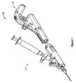
図1は、血管処置装置10の典型的な構成要素の1つの実施形態の斜視図を描いている。これらの構成要素は、血管処置装置10に対して一連の機能性を与えるように構成され得る。幾つかの実施形態において、血管処置装置10は、例えばワイヤ、モータなどの血管焼灼を促すように構成される機能部、及び/又は、制御機能部、及び/又は、例えばシースまたはカテーテルなどの液体を供給するように構成される機能部を含むことができる。図1に描かれるように、血管処置装置はハンドル12とカートリッジ14とを含むことができる。以下で更に詳しく説明するように、ハンドルおよびカートリッジのそれぞれは、血管焼灼を促すように及び/又は液体を供給するように構成される機能部を含むことができる。1つの実施形態では、図1に描かれるように、ハンドル12およびカートリッジ14が別個の部品を備えることができる。他の実施形態では、ハンドル12およびカートリッジ14が一体の構成要素を備えることができる。当業者であれば分かるように、本開示は、ハンドル12およびカートリッジ14の特定の形態に限定されず、血管治療装置の一連の機能および用途を広く含む。
FIG. 1 depicts a perspective view of one embodiment of typical components of a
図1に更に描かれるように、カートリッジ14は、例えば、ハンドル12に係合接続するように寸法付けられて形成され得る。1つの実施形態では、図1に示されるように、この係合接続は、ハンドル12の機能部をカートリッジ14の機能部に嵌め付けることによって達成され得る。
As further depicted in FIG. 1, the
図2は、ハンドル12およびカートリッジ14を有する血管処置装置10の同様の実施形態の側断面図を描いている。図2に描かれる血管処置装置10は、図1に関して論じられた同じ機能部を備える。当業者であれば分かるように、本開示は、ハンドル12およびカートリッジ14を備える血管処置装置10の実施形態に限定されず、後述するような血管処置装置10の機能性を広く包含する。
FIG. 2 depicts a side cross-sectional view of a similar embodiment of a
図1および図2に示されるカートリッジ14の実施形態が図3に更に詳しく示されている。血管処置装置10は管腔内部材を含むことができる。幾つかの実施形態では、管腔内部材がワイヤを備えることができる。幾つかの実施形態では、管腔内部材がワイヤを取り囲むシースを備えることができる。
The embodiment of the
図3に描かれるカートリッジ14は、カートリッジ14に取り付けられてカートリッジ14から延びるシース30、ワイヤ32、および、カップリング34を含む。幾つかの実施形態では、ワイヤ32を例えばカップリング34に固定することができる。当業者であれば分かるように、様々な技術および方法によってワイヤ32をカップリング34に取り付けることができる。また、当業者であれば分かるように、ワイヤ32を駆動させるように構成される血管処置装置10の一連の機能部に対してワイヤ32を取り付けることができる。シースおよびワイヤがカートリッジ14から出る場所に歪み緩和チューブ33を設けることができる。
The
ワイヤ32は、様々な材料および幾何学的形態を備えることができる。幾つかの実施形態において、ワイヤ32は、患者内への液体の注入を容易にするように構成され得る。例えば、ワイヤ32は、所望の注入ポイントへの流体の流れを可能にするように環状となることができ或いはチャネルを有することができる。同様に、シース30は、様々な材料および幾何学的形態を備えることができ、また、幾つかの実施形態では、患者内への液体の注入を容易にするように構成され得る。例えば、ワイヤを収容するように構成される環状シース30は、ワイヤ32の周囲の環状通路を通じた液体の注入を可能にするように更に構成され得る。
The
ワイヤ32は様々な長さを備えることができる。幾つかの実施形態において、ワイヤ32は、処置のニーズと適合する長さを有することができる。幾つかの実施形態において、ワイヤ32は、例えば、最大で10cmまで、最大で25cmまで、最大で75cmまで、あるいは、最大で150cmまでの長さを有することができる。
The
幾つかの実施形態では、ルーメンを画定するようにシース30を構成することができ、ルーメンと通じてワイヤ32が延びる。幾つかの実施形態において、シースは、該シース内でのワイヤの独立した動きを許容するように構成され得る。シース30は、様々な内径および外径を有することができる。幾つかの実施形態において、シース30は、約0.022インチ〜0.048インチの範囲の内径を有することができる。幾つかの実施形態において、シース30は、約0.025インチ〜0.051インチの範囲の外径を有することができる。幾つかの実施形態において、シース30の外径は、例えば標準的な注射針の内径と一致する範囲内となり得る。1つの実施形態において、例えば、シース30は、例えば約0.0035インチ〜0.00160インチ、約0.0160インチ〜0.0420インチ、約0.0420インチ〜0.0630インチ、または、約0.0115インチ〜0.0630インチの範囲内の内径を有する標準的な注射針または血管シース内に挿入できるように寸法付けられて形成され得る。
In some embodiments, the
幾つかの実施形態において、例えば、シース30は、様々な医師が処置を行なうことができるように十分に小さい注射針直径を通じて挿入できるように寸法付けられ得る。したがって、1つの実施形態では、シース30の最大外径を、例えば、様々な医師が処置を行なうことができるように十分に小さい針サイズである0.0039インチ未満の内径を有する静脈注射用針またはカテーテル通じてシース30を挿入できるように0.035インチ未満にすることができる。
In some embodiments, for example, the
シース30は、装置10の挿入速度または除去速度を監視するようにユーザを導いてもよい外部マークを一定の間隔で含んでもよい。
The
血管処置装置10の幾つかの実施形態は、注入物質と共に使用するように構成され得る。幾つかの実施形態において、カートリッジ14は、注入物質を保持するように構成され得る。注入物質を注入するように構成される血管処置装置の幾つかの実施形態は、注入物質を収容するための容器と、例えばポンプまたはシリンジなどの注入機能部とを含むことができる。カートリッジ14の幾つかの実施形態では、シリンジ36がカートリッジ14と流体接続できる。注入物質に関連して使用するように構成される血管処置装置10及び/又はカートリッジ14の幾つかの実施形態は、例えば、そのような使用を容易にするためにバルブおよびコネクタを伴って構成され得る。幾つかの実施形態において、シリンジ36は、例えば、カートリッジ14のストップコック38に接続され得る。図3に示されるストップコック38は、処置中に血管処置装置10に対するシリンジの除去及び/又は取り付けを可能にするように構成され得る。幾つかの実施形態において、ストップコック38は、例えば注入物質または注入物質の濃度を変えるために流体の再充填及び/又は容器の交換を行なうことができるように構成され得る。幾つかの実施形態において、ストップコック38は、例えば注入物質を混合する或いは注入物質に空気を混入するなどの更なる機能性を与えるように構成され得る。
Some embodiments of the
図4は、ハンドル12の1つの典型的な実施形態の側断面図を描いている。ハンドル12を例えば1つの部品または幾つかの部品から形成することができる。また、例えば天然材料、合成材料、金属、高分子、ガラス、複合体、または、これらの任意の組み合わせなどの様々な材料から様々な技術を使用してハンドル12を形成することができる。幾つかの実施形態では、ハンドル12は、例えば、2つの外側ケーシング部品を結合することによって形成することができる。
FIG. 4 depicts a cross-sectional side view of one exemplary embodiment of the
ハンドル12がカートリッジ14から離れる幾つかの実施形態において、ハンドル12は、カートリッジ14を受けるように構成されるレセプタクル40を形成できる。図4に描かれるように、レセプタクル40は例えば雄カップリング42を含むことができ、この雄カップリング42は、例えばカップリング14とハンドル12とが係合するときにカートリッジ14の雌カップリング34を受けるように構成されて位置され得る。幾つかの実施形態において、ハンドル12は、例えば、少なくとも1つのモータ44を含むことができる。図4に描かれるハンドル12の典型的な実施形態は、モータ44、トリガ46、および、雄カップリング42を含むことができる。図4にも描かれるように、幾つかの実施形態において、雄カップリング42は、モータ44が起動時に雄カップリング42を駆動させるようにモータ44に駆動可能に接続され得る。
In some embodiments where the
血管処置装置10は、管腔内部材の動きを制御するように構成され得る。幾つかの実施形態では、モータ44が管腔内部材の動きを制御できる。血管処置装置10の幾つかの実施形態において、モータ44は、例えばワイヤ32などの管腔内部材を回転可能に駆動させることができる。
幾つかの実施形態では、ポテンショメータ48をモータ44に電気的に結合させることができ、また、モータ44の速度を制御するようにポテンショメータ48を構成できる。幾つかの実施形態では、制御機能部がモータ44を制御できる。幾つかの実施形態において、制御機能部は、血管処置装置10と機械的に接続でき、電気的に接続でき、または、通信接続でき、例えば無線接続でき或いはブルートゥースにより接続できる。幾つかの実施形態では、制御機能部がトリガ46を備えることができる。トリガ46を例えばハンドル12に取り付けることができ、また、モータ44が電源52に電気的に結合されない第1の状態と、モータ44が電源52と電気的に結合される第2の状態との間でトリガ46を移行させることができる。
In some embodiments, the potentiometer 48 can be electrically coupled to the motor 44 and the potentiometer 48 can be configured to control the speed of the motor 44. In some embodiments, the control function can control the motor 44. In some embodiments, the control function can be mechanically connected to the
血管処置装置10の幾つかの実施形態では、前述したように、モータ44の起動がワイヤ32の回転を引き起こすことができる。幾つかの実施形態において、血管処置装置10は、ワイヤ32の所望の回転速度を発生させるように構成され得る。幾つかの実施形態において、例えば、モータ44は、最大で約100rpmまで、最大で500rpmまで、最大で1000rpmまで、または、最大で5000rpmまでワイヤ32を回転させるように構成され得る。血管処置装置10が静脈瘤処置および血栓切除処置で使用するように構成される幾つかの実施形態では、モータ44を500〜4000rpmの速度用に構成することができる。血管処置装置10の幾つかの実施形態は、例えば内蔵RPMディスプレイなどの少なくとも1つのフィードバック機能部を更に備える。当業者であれば分かるように、ワイヤ32の広範囲の回転速度を発生させるように血管処置装置10を構成することができ、また、本開示は任意の特定の回転速度に限定されない。
In some embodiments of the
図4に描かれるように、ハンドル12の幾つかの実施形態は、例えば、モータ44に接続されるマイクロスイッチ54および電源52を含むことができる。マイクロスイッチ54は、トリガ46とモータ44とを接続する電気回路内に介挿されてもよい。マイクロスイッチ54は、トリガ46とモータ44との間の回路が開くように開位置へと付勢されてもよい。カートリッジ14がハンドル12に係合されると、カートリッジがマイクロスイッチ54を押圧して、それにより、マイクロスイッチが閉状態へと移行し、その結果、トリガ46とモータ44とを接続する電気回路が完成してもよい。例えば、マイクロスイッチ54が2つの接点を含んでもよく、その場合、マイクロスイッチ54が開状態にあるときには、導体が一方の接点に取り付けられるとともに第2の接点から取り外される。1つの実施形態において、導体は、チャネル内に垂れ下がる金属のストリップを含んでもよく、カートリッジ14がハンドルとの係合中に前記チャネル内へとスライドされる。カートリッジ14がハンドル12に係合されると、カートリッジは、金属ストリップをチャネルから押し出してマイクロスイッ54の第2の接点に接続させる。そのような形態により得られる1つの利点は、ユーザが装置の使用準備を行う前に、すなわち、カートリッジ14がハンドル12に完全に係合される前に、ユーザがトリガ46を押すことにより不注意に装置を起動させることができないという点かもしれない。
As depicted in FIG. 4, some embodiments of the
ハンドル12とカートリッジ14とが別個の構成要素である幾つかの実施形態では、図4に示されるようにハンドル12が例えばスイッチ56を含むことができる。スイッチ56は、例えば、カートリッジ14をハンドル12によって受けてハンドル12に固定できるように構成され得る。スイッチ56は、幾つかの実施形態では、ユーザが指でスイッチ56を操作できるように構成されるグリップ58を含む。
In some embodiments where the
幾つかの実施形態では、ハンドル12の1つ以上の部分がトリガリング60を形成でき、トリガリング60内にトリガ46の少なくとも一部が配置され、また、トリガリング60の周囲に、ハンドル12を、例えば、トリガリング60を形成するハンドル12の1つ以上の部分だけから支持されるときに釣り合わされるように配置することができる。幾つかの実施形態において、最も重い構成要素を例えばトリガ46の下側に位置させることができる。幾つかの態様では、トリガ46の下側に最も重い構成要素を位置させることが、ハンドルを適切に釣り合わせることに役立ち得る。モータ44が例えば最も重い構成要素である幾つかの実施形態では、図4に示されるようにモータ44をトリガ46の下側に位置させることができる。
In some embodiments, one or more portions of the
ハンドル12は、例えば、液体の収容および注入を容易にするように構成される機能部を含むことができる。幾つかの実施形態において、ハンドル12は、例えば、シリンジを受けるように位置される支持体62を含むことができる。支持体62は、様々なサイズおよび形状を有することができる。幾つかの実施形態において、支持体62は、例えば標準的なシリンジなどの指定された容器に適合するように寸法付けられて形成され得る。支持体62は、更なる実施形態では、注入中に容器が落ちるのを防止するように構成され得る。幾つかの実施形態において、支持体62は、容器と接続係合するように構成され得る。1つの実施形態において、例えば、シリンジは、該シリンジが取り付けられたカートリッジ14がハンドル12に係合されるときに支持体62にスナップ係合してもよい。
The
血管処置装置の実施形態の前述した構成要素および他の構成要素のうちの幾つかの更に詳しい説明は、米国特許出願公開第2005/0055040号明細書および米国特許出願公開第2009/0270889号明細書において見出すことができ、これらの出願はそれらの全体が参照することにより本願に組み入れられる。一般に、図1〜図4に描かれる装置は、焼灼されるべき静脈内へワイヤおよびシースを送り込んで静脈内壁の内皮を損傷させるべくワイヤの先端を静脈に対して回転させる或いはさもなければ移動させることにより血管を焼灼するために使用される。この損傷プロセスの前、該プロセス中、あるいは、該プロセスの後、前述したようなシースまたはワイヤを通じて硬化剤が静脈内へ注入される。損傷と硬化剤との複合効果は、非常に良好な焼灼処置をもたらす。 A more detailed description of some of the aforementioned components and other components of embodiments of vascular treatment devices can be found in US Patent Application Publication No. 2005/0055040 and US Patent Application Publication No. 2009/0270889. And these applications are hereby incorporated by reference in their entirety. In general, the device depicted in FIGS. 1-4 will rotate or otherwise move the tip of the wire relative to the vein to feed the wire and sheath into the vein to be ablated and damage the endothelium of the venous wall. Is used to cauterize blood vessels. Prior to, during, or after the injury process, sclerosing agent is injected intravenously through a sheath or wire as described above. The combined effect of damage and hardener results in a very good cauterization treatment.
これらの処置を行なう際、医師は、通常、ワイヤを用いた削りプロセスおよび静脈損傷プロセスを開始すると同時に、ワイヤを当初のアクセスポイントへ向けて静脈の下方へゆっくりと引き戻し、それにより、焼灼されるべき静脈の大きな部分に沿って削る。除去の速度は一般に毎秒数mmであり、毎秒1〜4mmが適していると思われる。しかしながら、比較的一定の除去速度を手作業で維持することは困難であると思われてきた。医師は、毎秒ほんの数ミリメートルで数十センチメートルのワイヤを引き出したいと思う場合がある。また、血管壁に対してワイヤ先端によって引き起こされる損傷の大きさを制御することにより得られる利点は、血管処置装置を手で引くときには得ることが難しい。これは、数十センチメートルの長さにわたって一定の引き抜き速度を維持することが困難であることにより生じ得る。 In performing these procedures, the physician typically initiates a wire shaving and vein damage process, while at the same time slowly pulling the wire back down the vein towards the original access point, thereby cauterizing Sharpen along a large part of the venous vein. The removal rate is generally a few millimeters per second, and 1 to 4 mm per second appears to be suitable. However, it has been considered difficult to manually maintain a relatively constant removal rate. Doctors may want to pull tens of centimeters of wire at just a few millimeters per second. Also, the advantages obtained by controlling the magnitude of damage caused by the wire tip to the vessel wall are difficult to obtain when pulling the vessel treatment device by hand. This can be caused by the difficulty of maintaining a constant drawing speed over a length of tens of centimeters.
幾つかの実施形態において、血管処置装置は、ワイヤ先端が血管壁と係合する度合いを制御するための機能部を含むことができる。血管処置装置10は、例えば、第1のモータおよび第2のモータに関連して使用され得る。第1のモータ44および第2のモータに関連して使用される血管処置装置10の幾つかの実施形態において、第1のモータ44は、ワイヤ32を制御可能に回転させるように構成され得る。第1のモータ44および第2のモータを有する血管処置装置10の幾つかの更なる実施形態において、第2のモータは、元のアクセスポイントへ向けたワイヤ32の長手方向の並進を制御するように構成され得る。幾つかの実施形態において、血管処置装置10は、ワイヤ32を所定の速度で回転させると同時にワイヤ32を所定の速度で長手方向に並進させるように構成される機能部を含むことができる。幾つかの実施形態では、ワイヤ32の回転および長手方向並進の速度を互いに関連付けることができる。幾つかの実施形態では、ワイヤ32の回転及び/又はワイヤ32の長手方向の並進の速度を血管治療処置の全体にわたって変えることができる。他の実施形態では、ワイヤ32の回転及び/又はワイヤ32の長手方向の並進の速度をユーザ制御または他の情報に応じて変えることができる。幾つかの実施形態では、フィーダーが、ワイヤ32を長手方向に並進させるように構成される第2のモータを備えることができる。フィーダーは、幾つかの実施形態では、管腔内部材を長手方向に制御可能に並進させるように構成され得る。当業者も分かるように、フィーダーは、ワイヤの様々な長手方向並進長さをもたらすように構成され得る。例えば並進装置の幾つかの実施形態は、最大で50cmまで、75cmまで、または、100cmを超える長手方向並進を与えるように構成され得る。血管治療装置の幾つかの実施形態は、例えば、毎秒0mm〜約20mmの速度でワイヤを長手方向に並進させることができる。前述したように、毎秒1〜4mmの制御可能な速度が多くの処置で有用となり得る。
In some embodiments, the vascular treatment device can include a feature for controlling the degree to which the wire tip engages the vessel wall. The
図5は、ワイヤの回転速度およびワイヤの長手方向の並進速度の両方を制御できるように構成される血管治療器具の1つの実施形態を描いている。図5は、長尺なトラック502を備えるフィーダー500を描いている。長尺なトラック502は、様々な形状および寸法を備えることができる。図5に描かれる実施形態では、長尺なトラック502がU形状の長尺部材を備える。トラック502は、図1〜図4に関連して先に説明される血管処置装置504を保持するように構成され得る。幾つかの実施形態において、トラック502は、少なくとも1つのローラ、少なくとも1つのベアリング、少なくとも1つのブシュ、少なくとも1つの空気噴流、少なくとも1つの磁石、または、他の機能部を含む血管処置装置504の長手方向の並進を容易にするための機能部を伴って構成され得る。図5は、ベルト506を備えるトラック502の1つの実施形態を描いている。ベルトは、長尺部材の底部に沿って延びており、トラック502の中空の底部を通じて戻る。ベルト506は、該ベルトを血管処置装置504に接続するための機能部を含むことができる。幾つかの実施形態において、これらの機能部は、面ファスナ(loop and hook fasteners)、磁石、クランプ、接着ストリップ、または、他の機能部を備えることができる。1つの特定の実施形態において、ベルト506は、面ファスナのフック部またはループ部のいずれかを備えることができる。ベルト706と関連付けられる面ファスナの部分をベルトと一体形成することができ或いはベルト706に例えば機械的に又は接着して取り付けることができる。血管処置装置704は、血管処置装置704の底部に取り付けられる面ファスナの他方の半体を血管処置装置704の面ファスナのこの半体がベルト706に位置される面ファスナの半体と接触状態に至らされ得るように備えるべく構成され得る。
FIG. 5 depicts one embodiment of a vascular treatment device configured to be able to control both the rotational speed of the wire and the longitudinal translation speed of the wire. FIG. 5 depicts a
図5は、ベルト506がモータ512によって駆動されるトラック502の1つの実施形態を描いている。モータ512は、ベルト506を有するトラック502の特定の実施形態の出力要件および速度要件と適合するように選択され得る。当業者であれば分かるように、様々なモータをベルト506に関連して使用できる。モータ512の速度を制御機能部によって制御できる。図5は、制御機能部518の1つの実施形態を描いている。ポテンショメータがトラック502の中空の底部の内側でモータ制御回路に結合されてもよい。この実施形態では、コントローラ518がトラック502に位置される。他の実施形態では、コントローラ518をトラック502から分離できる。器具は、フィーダー700の動作に関する情報を術者に与えるディスプレイなどのフィードバック機能部を更に備えることができる。
FIG. 5 depicts one embodiment of a
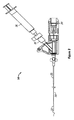
トラック502を備えるフィーダー500の実施形態は自立的となることができ或いは他の物体に取り付けられ得る。図5に描かれる実施形態では、フィーダー500が関節アーム508に取り付けられる。当業者であれば分かるように、関節アームは、様々な材料から形成されて様々な方法で組み付けられる様々な構成要素を備えることができる。幾つかの実施形態では、図5に描かれるように、関節アームは、該アームを物体に取り付けるための機能部を含むことができる。幾つかの実施形態において、これらの機能部は例えばCクランプを含むことができる。1つの実施形態において、Cクランプは、関節アームの端部に位置されて、例えば手術台または病院のベッドに対する関節アームの固定を可能にするように構成され得る。
Embodiments of
処置中、医師は、装置504のハンドルを保持し、それにより、前述したようにワイヤ回転および血管損傷を開始するべくトリガを押し下げる。これが始まる前または始まった後に、モータ512を始動させて、装置がベルト506によりトラックに沿って引き戻されるべき所望の速度にモータ512を調整することができる。装置もトラック内において所望の速度で引き戻されるため、ハンドルのレバー、ボタン、または、他の制御機能部を利用して、手を使わないで操作できるワイヤ回転を可能にすることができる。
During the procedure, the physician holds the handle of the
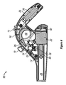
図6Aは、ワイヤの長手方向の並進を自動態様で制御するように構成される機構の1つの実施形態を描いている。図6Aは、回転するワイヤまたはワイヤ/シースの組み合わせ602を長手方向に並進させるように構成されるフィーダー600を描いている。フィーダー600はハウジング604を備える。ハウジング604は、例えば天然材料、合成材料、高分子、金属、ガラス、複合体、または、任意の他の材料などの様々な材料から形成され得る。ハウジング604は様々な形状およびサイズを有することができる。ハウジングは、例えば少なくとも1つのモータ、少なくとも1つのギア、配線、少なくとも1つのローラ、少なくとも1つのブシュ、少なくとも1つのベアリング、少なくとも1つのアンテナ、少なくとも1つのスイッチ、少なくとも1つのコンピュータチップ、少なくとも1つのポンプ、または、他の構成要素などの様々な構成要素を覆うことができる。図6Aに描かれるハウジングは、開放した上端606、底部(図示せず)、患者に対して相対的に最も近くに位置されてワイヤがフィーダー内へと通ることができるようにする第1の面608、装置に対して相対的に最も近くに位置されてワイヤがフィーダーを通り抜けることができるようにする第2の面(図示せず)、第1の側面610、および、第2の側面(図示せず)を有する。図6Aに描かれるように、第1の面608は、ワイヤ602が第1の面608の平面を通過できるように構成される第1のスロット612を含むことができる。同様に、第2の面は、ワイヤ602が術者の方の平面を通過できるように構成される第2のスロット614を含むことができる。幾つかの実施形態において、スロットは、ワイヤ602をフィーダー600のハウジング604内に配置できるように構成され得る。
FIG. 6A depicts one embodiment of a mechanism configured to control the longitudinal translation of the wire in an automatic manner. FIG. 6A depicts a
幾つかの実施形態では、フィーダー600が自立できる。他の実施形態では、フィーダー600を例えばテーブルなどの物体に取り付けることができる。図6Aに描かれるように、1つの実施形態では、フィーダーを関節アーム616に取り付けることができる。関節アーム616は、フィーダー600を患者の身体に対して所望の位置に位置決めできるように構成され得る。関節アーム616は、例えば、テーブル、カート、椅子、壁、または、他の適した物体に取り付け固定され得る。他の実施形態において、関節アーム616は、様々な所望の物体に選択的に取り付けることができるようにする機能部を含むことができ、そのような機能部としては、例えば、少なくとも1つのクランプ、少なくとも1つの吸引カップ、少なくとも1つの磁石、少なくとも1つの接着処理領域、または、様々な他の取付機能部が挙げられる。
In some embodiments, the
図6Aは制御器618を更に描いている。制御器は、例えば送り速度などのフィーダーの機能の態様を制御するように構成され得る。図6Aに描かれるように、制御器618をフィーダー500の側面506に位置させることができる。他の実施形態では、制御器618を様々な任意の位置に位置付けることができ或いはフィーダー600に接続することができる。幾つかの実施形態では、制御器を例えばフィーダー600と通信接続することができる。この接続は、例えば、機械的、電気的、光学的、無線により行なうことができ、あるいは、任意の様々な他の接続によって行なうことができる。
FIG. 6A further depicts
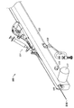
図6Bは、シース及び/又はワイヤ602を長手方向に並進させるように構成されるフィーダー600の1つの実施形態の平面図を描いている。図6Bに描かれるように、フィーダー600はハウジング604を備える。図6Bに描かれるハウジング604は、少なくとも第1のローラ606および第2のローラ608を取り囲む。ローラ606,608は、様々なタイプ、形状、および、サイズを備えることができる。幾つかの実施形態では、例えば、ローラ606,608を円柱状のローラにすることができる。他の実施形態では、ローラを例えば球状ローラにすることができる。幾つかの実施形態では、ローラのうちの少なくとも一方608を駆動ローラにすることができる。幾つかの実施形態では、駆動されるローラを例えばモータに対して、直接に、ギアによって、ベルトによって、あるいは、様々な他の機能部によって接続することができる。図6Bに描かれる実施形態では、ローラ608が駆動されるローラであり、ローラ606が自由に回転する遊動ローラである。当業者であれば分かるように、本開示は、ローラ606,608の特定の形状、サイズ、または、駆動特性に限定されない。
FIG. 6B depicts a top view of one embodiment of a
ローラ606,608は、フィーダー600の異なる実施形態では、異なる位置を有することができる。図6Bに描かれる上側ローラ606および下側ローラ608は、ワイヤ602が2つのローラ606,608間を通ることができるように位置される。幾つかの実施形態では、ローラによってワイヤ602に及ぼされる圧縮力を一定にすることができ或いは可変にすることができる。幾つかの実施形態において、ローラ間の相対距離は、ローラ606,608によってワイヤ602にもたらされる圧縮力を変えるように変更できる。ローラ606,608は様々な材料を更に備えることができる。幾つかの実施形態において、ローラは、天然材料、合成材料、高分子、複合体、金属、ガラス、または、任意の他の材料を備えることができる。幾つかの実施形態において、ローラ606,608は、例えば、ワイヤ602に対してローラ606,608により及ぼされる圧縮力を制御するように選択される材料を備えることができる。1つの実施形態において、例えば、ワイヤ602に対してローラ606,608により及ぼされる圧縮力は、ローラ606,608を圧縮性材料から形成することによって制御され得る。当業者であれば分かるように、本開示は、任意の特定のローラ形態に限定されず、多種多様なローラを広く包含する。
The
幾つかの実施形態では、第1のローラ606及び/又は第2のローラ608を位置間の移動を可能にするための様々な機構に接続することができる。1つの実施形態では、図6Bに描かれるように、第1のローラ606をバネ荷重可動アーム610の端部に位置させることができる。1つの実施形態において、可動アーム610は、該アーム、したがって第1のローラ606が第2のローラ608から離間される開位置を備えることができる。この位置では、ワイヤ602を図6aに描かれるスロット内へ移動させて第1のローラ606と第2のローラ608との間に位置させることができる。その後、可動アーム、したがって第1のローラ606が第2のローラ608に近接して位置されてそれによりワイヤ602を第1のローラ602と第2のローラ608との間に保持する第2の位置へと可動アームを移動させることができる。
In some embodiments, the
幾つかの実施形態において、シース及び/又はワイヤ602は、ワイヤを取り囲む管状シースを備えることができる。管状シースがワイヤを取り囲む実施形態において、ワイヤは、前述した血管治療装置内でワイヤを回転駆動させるように構成される第1のモータに接続され得る。ローラ606,608は、例えば、ローラ606,608がシースを長手方向に駆動させることができるようにシースに対して十分な圧縮力を印加するべく構成され得る。また、ローラ606,608は、シース内でのワイヤの回転を防止する或いは抑制するように不十分な圧縮力を発生させるべく構成され得る。これは、アーム610を付勢して遊動ローラ606を駆動ローラ608と係合させるバネ力の選択によって制御され得る。
In some embodiments, the sheath and / or
フィーダー600は、ローラ606,608のうちの少なくとも一方の回転を制御することによってシース及び/又はワイヤ602の長手方向の並進を制御することができ、その回転は、シース及び/又はワイヤ602をローラ606,608の回転方向に送る。
The
図6Cは、図6Bに描かれるフィーダー600の切断正面図を描いている。図6Cは、可動アーム610の端部に接続される第1のローラ606と、モータ612に駆動可能に接続される第2のローラ608とを描いている。図6Cにも描かれるように、第1のローラ606はホイール面614とフランジ616とを備える。ホイール面606をワイヤと接触するように構成することができる。フランジ616は、幾つかの実施形態では、ワイヤが第1のローラ606と第2のローラ608との間の領域から移動するのを防止するように構成され得る。また、図6Cにも描かれるように、モータ612をコントローラ618に接続できる。コントローラ618は、モータ、したがって第2のローラ608の回転の選択的な速度制御を可能にするように構成され得る。
FIG. 6C depicts a cut front view of the
図6A−図6Cのフィーダーを使用するときには、医師は、最初にワイヤ/シースを患者の静脈内へ配置し、その後、ワイヤ/シースの一部をフィーダー内およびローラ間に取り付ける。静脈の損傷は、前述した血管治療装置10のトリガを作動させることによって開始され得る。この作動の前または後に、モータ620を所望の引き出し速度で起動させることができる。フィーダーがワイヤ/シースを引き戻す際に、装置10を手動で引き戻すことができる。シース内でのワイヤの回転動作を妨げる急激な屈曲が形成されさえしなければ、フィーダーから出る余分なワイヤ/シースを幾分下方へ垂らして掛けることもできる。
When using the feeder of FIGS. 6A-6C, the physician first places the wire / sheath into the patient's vein and then attaches a portion of the wire / sheath within the feeder and between the rollers. Vein damage can be initiated by actuating the trigger of the
この開示に基づき、当業者であれば分かるように、様々な技術および機構は、ワイヤの長手方向の並進速度を制御して調整するように構成され得る。また、当業者であれば分かるように、これらの技術および機構は、例えば所望のワイヤ動作の度合い、装置の目標価格、および、サイズ制約を含む様々なファクタに基づいて実施するように選択され得る。更に、当業者であれば分かるように、本開示は、ワイヤの長手方向の並進の速度および広範囲の速度を制御するための広範囲の機構および技術を含む。 Based on this disclosure, as will be appreciated by those skilled in the art, various techniques and mechanisms may be configured to control and adjust the longitudinal translational speed of the wire. Also, as will be appreciated by those skilled in the art, these techniques and mechanisms may be selected to be implemented based on various factors including, for example, the desired degree of wire motion, the target price of the device, and size constraints. . Furthermore, as will be appreciated by those skilled in the art, the present disclosure includes a wide range of mechanisms and techniques for controlling the rate of longitudinal translation of the wire and a wide range of speeds.
前述した実施形態のそれぞれは、制御・フィードバック機能性を含むように構成され得る。幾つかの実施形態において、フィーダーおよび血管処置装置は、例えば、配線、少なくとも1つのセンサ、少なくとも1つのマイクロプロセッサ、少なくとも1つの入力可能機能部、および、他の制御要素または検出要素を含むことができる。これらの構成要素は、シース及び/又はワイヤが移動している速度を検出してその速度を調整する或いは変更するように構成され得る。 Each of the embodiments described above can be configured to include control and feedback functionality. In some embodiments, the feeder and vascular treatment device may include, for example, wiring, at least one sensor, at least one microprocessor, at least one input enabled function, and other control or detection elements. it can. These components may be configured to detect the speed at which the sheath and / or wire is moving and adjust or change that speed.
当業者であれば分かるように、これらの構成要素のそれぞれを様々な技術およびハードウェアを使用して相互に接続でき且つ制御可能に接続することができ、また、本開示は、任意の特定の接続方法または接続ハードウェアに限定されない。幾つかの態様では、図に描かれる構成要素のうちの1つ以上を排除することができ、また、必要に応じて、更なる構成要素を含むこともできる。 As those skilled in the art will appreciate, each of these components can be interconnected and controllably connected using a variety of technologies and hardware, and the disclosure is not limited to any particular It is not limited to the connection method or connection hardware. In some aspects, one or more of the components depicted in the figures can be eliminated and further components can be included as needed.
前述した説明は、本明細書中に開示される装置および方法の特定の実施形態を詳述する。しかしながら、以上の説明が本文中でいかに詳しく見えようとも、装置および方法を多くの態様で実施できることは言うまでもない。また、前述したように、本発明の特定の特徴または態様について説明するときの特定の用語の使用は、その用語が関連付けられる技術の特徴または態様の任意の特定の特性を含むべく限定されるように前記用語が本明細書中で再定義されるべきことを意味していると解釈されるべきでないことに留意すべきである。 The foregoing description details specific embodiments of the devices and methods disclosed herein. It will be appreciated, however, that no matter how detailed the foregoing appears in the text, the device and method can be implemented in many ways. Also, as discussed above, the use of a particular term when describing a particular feature or aspect of the invention is intended to be limited to include any particular characteristic of the technical feature or aspect with which the term is associated. It should be noted that the above terms should not be construed to mean that they are to be redefined herein.
当業者であれば分かるように、前述した技術の範囲から逸脱することなく、様々な改良および変更がなされてもよい。そのような改良および変更は、実施形態の範囲内に入るべく意図される。また、当業者であれば分かるように、1つの実施形態に含まれる部品は他の実施形態と置き換えることができ、また、1つの描かれた実施形態からの1つ以上の部品を他の描かれた実施形態と共に任意の組み合わせで含めることができる。例えば、本明細書中で説明された及び/又は図に描かれた様々な構成要素のうちのいずれかが、組み合わされてもよく、置き換えられてもよく、あるいは、他の実施形態から排除されてもよい。 As will be appreciated by those skilled in the art, various modifications and changes may be made without departing from the scope of the foregoing technology. Such improvements and modifications are intended to fall within the scope of the embodiments. Also, as those skilled in the art will appreciate, parts included in one embodiment can be replaced with other embodiments, and one or more parts from one drawn embodiment can be replaced with other drawings. Can be included in any combination with the described embodiments. For example, any of the various components described herein and / or depicted in the figures may be combined, replaced, or excluded from other embodiments. May be.
本明細書中におけるほぼ任意の複数形及び/又は単数形の用語の使用に関して、当業者は、文脈及び/又は用途に適するように、複数形から単数形へ置き換えることができ、及び/又は、単数形から複数形へ置き換えることができる。言うまでもなく、明確にするために、様々な単数形及び/又は複数形の置き換えが本明細書中に記載されてもよい。 With respect to the use of almost any plural and / or singular terms herein, one of ordinary skill in the art can substitute from the plural to the singular and / or to suit the context and / or application, and / or It is possible to replace the singular form with the plural form. Of course, various singular and / or plural substitutions may be described herein for clarity.
当業者であれば分かるように、一般に、本明細書中で使用される用語は、通常、”開かれた”用語として意図される(例えば、”含んでいる”という用語は”含んでいるがそれに限定されない”として解釈されるべきであり、”有している”という用語は”少なくとも有する”として解釈されるべきであり、”含む”という用語は”含むがそれに限定されない”等として解釈されるべきである)。また、当業者であれば分かるように、請求項における特定数の前置きの列挙が意図される場合には、そのような意図は請求項に明確に列挙され、また、そのような列挙が存在しない場合には、そのような意図が存在しない。例えば、理解の補助として、以下の添付の請求項は、請求項における列挙を前置きするために前置きの語句”少なくとも1つ”および”1つ以上”の使用を含む場合がある。しかしながら、そのような語句の使用は、不定冠詞”1つ(a)”または”1つ(an)”による請求項における列挙の前置きが、同じ請求項が前置きの語句”1つ以上”または”少なくとも1つ”および”1つ(a)”または”1つ(an)”(例えば、”1つ(a)”及び/又は”1つ(an)”は、一般に、”少なくとも1つ”または”1つ以上”を意味するように解釈されるべきである)などの不定冠詞を含む場合であっても、そのような前置きされた請求項の列挙を含む任意の特定の請求項を、1つのそのような列挙のみを含む実施形態に限定することを意味するように解釈されるべきではない。これと同じことは、請求項の列挙を前置きするために使用される定冠詞の使用についても当てはまる。また、請求項における特定数の前置きの列挙が明確に列挙される場合であっても、当業者であれば分かるように、そのような列挙が一般に少なくとも列挙された数(例えば、他の修飾語句を伴わない”2つの列挙”のありのままの列挙は、一般に、少なくとも2つの列挙、または、2つ以上の列挙を意味する)を意味するように解釈されるべきである。また、当業者であれば分かるように、2つ以上の代替用語を与えるほぼ任意の離接語及び/又は語句は、明細書本文中であろうと、特許請求の範囲の中であろうと、あるいは、図面中であろうと、それらの用語のうちの一方、それらの用語のうちのいずれか、あるいは、それらの用語の両方を含む可能性を考えるように理解されるべきである。例えば、語句”AまたはB”は、”A”または”B”もしくは”AおよびB”可能性を含むように理解され得る。 As will be appreciated by those skilled in the art, in general, the terms used herein are generally intended as “open” terms (eg, the term “including” includes “ The term “having” should be interpreted as “having at least”, the term “including” should be interpreted as “including but not limited to”, etc. Should be). It will also be appreciated by those skilled in the art that when a specific number of prefixes in a claim are intended, such intent is explicitly recited in the claim and there is no such list. In some cases there is no such intention. For example, as an aid to understanding, the following appended claims may include use of the introductory phrases “at least one” and “one or more” to precede the enumeration in the claims. However, the use of such a phrase is that the indefinite article “one (a)” or “one (1)” in the claim is an enumeration in the claim, and the same claim is preceded by the phrase “one or more” or “ “At least one” and “one (a)” or “one” (eg, “one (a)” and / or “an”) are generally referred to as “at least one” or Any particular claim that contains a list of such preceding claims, even if it contains an indefinite article such as “which should be interpreted to mean“ one or more ”. It should not be construed to mean limited to embodiments containing only one such list. The same is true for the use of definite articles that are used to prefix claim enumeration. Also, even if a specific number of preceding enumerations in a claim are explicitly enumerated, as those skilled in the art will appreciate, such enumerations are generally at least enumerated (e.g., other modifiers). The unambiguous list of “two enumerations” without a general meaning should generally be interpreted to mean at least two enumerations or two or more enumerations). It will also be appreciated by those skilled in the art that almost any disjunctive word and / or phrase that provides two or more alternative terms may be used in the specification text, in the claims, or It should be understood that in the drawings, the possibility of including one of the terms, any of the terms, or both of the terms is included. For example, the phrase “A or B” may be understood to include “A” or “B” or “A and B” possibilities.
本明細書中で挙げられる全ての引用文献は、参照することによりそれらの全体が本願に組み入れられる。引用文献により組み入れられる刊行物および特許または特許出願が本明細書中に含まれる開示と矛盾する範囲まで、本明細書は、任意のそのような矛盾材料に優先する及び/又はそのような矛盾材料に勝るように意図される。 All references cited herein are hereby incorporated by reference in their entirety. To the extent that publications and patents or patent applications incorporated by reference contradict the disclosure contained herein, this specification supersedes any such conflicting material and / or such conflicting material. Is intended to win.
本明細書中で使用される”備えている”という用語は、”含んでいる”、”包含している”、または、”により特徴付けられる”と同義であるとともに、包括的または無制限な用語であって、更なる列挙されない要素または方法ステップを排除しない。 As used herein, the term “comprising” is synonymous with “including,” “including,” or “characterized by” and is an inclusive or unlimited term It does not exclude further unlisted elements or method steps.
Claims (18)
被検体の血管を通過するように形成されて寸法付けられるとともに、基端と先端とを有し、管腔が前記基端から前記先端まで延びるよう特徴づけられるシースと、前記基端から前記先端まで延びる管腔内に配置され、前記シースに対して回転可能であるワイヤとを備える長尺管腔内部材と、
前記長尺管腔内部材の前記先端に流体を供給するように構成される流体チャネルと、
前記ワイヤに結合され、前記ワイヤが前記シースに対して回転するように構成される第1のモータと、
前記第1のモータが前記ワイヤを前記シースに対して回転させると同時に、前記管腔内部材を引き出すように構成され、前記管腔内部材に結合される第2のモータとを備える器具。 Veins A device for causing the closed infarction,
A sheath formed and dimensioned to pass through a blood vessel of a subject and having a proximal end and a distal end and characterized by a lumen extending from the proximal end to the distal end; and from the proximal end to the distal end A long intraluminal member comprising a wire disposed within the lumen extending to and rotatable with respect to the sheath ;
A fluid channel configured to supply fluid to the distal end of the previous SL elongate lumen member,
A first motor coupled to the wire and configured to rotate with respect to the sheath ;
An instrument comprising: a second motor configured to pull out the intraluminal member and coupled to the intraluminal member while the first motor rotates the wire relative to the sheath .
被検体の血管を通過するように形成されて寸法付けられるとともに、基端と先端とを有し、管腔が前記基端から前記先端まで延びるよう特徴づけられるシースと、前記基端から前記先端まで延びる管腔内に配置され、前記シースに対して回転可能であるワイヤとを備える長尺管腔内部材と、
前記長尺管腔内部材の前記先端に流体を供給するように構成される流体チャネルと、
前記ワイヤに結合され、前記ワイヤが前記シースに対して回転するように構成される第1のモータと、
前記第1のモータが前記ワイヤを前記シースに対して回転させると同時に、前記管腔内部材を長手方向に並進させるように構成され、前記管腔内部材に結合される第2のモータとを備え、
前記第1のモータが第1のハウジングに結合され、前記第2のモータがフィーダーに結合される器具。 Veins A device for causing the closed infarction,
A sheath formed and dimensioned to pass through a blood vessel of a subject and having a proximal end and a distal end and characterized by a lumen extending from the proximal end to the distal end; and from the proximal end to the distal end A long intraluminal member comprising a wire disposed within the lumen extending to and rotatable with respect to the sheath ;
A fluid channel configured to supply fluid to the distal end of the previous SL elongate lumen member,
A first motor coupled to the wire and configured to rotate with respect to the sheath ;
A first motor configured to translate the intraluminal member in a longitudinal direction at the same time as the first motor rotates the wire relative to the sheath; and a second motor coupled to the intraluminal member; Prepared,
An instrument in which the first motor is coupled to a first housing and the second motor is coupled to a feeder.
被検体の血管を通過するように形成されて寸法付けられるとともに、基端と先端とを有し、管腔が前記基端から前記先端まで延びるよう特徴づけられるシースと、前記基端から前記先端まで延びる管腔内に配置され、前記シースに対して回転可能であるワイヤとを備える長尺管腔内部材と、
前記ワイヤが前記シースに対して回転するように構成される第1のモータと、
前記第1のモータが前記ワイヤを前記シースに対して回転させると同時に、前記管腔内部材を引き出すように構成される第2のモータとを備える器具。 Veins A device for causing the closed infarction,
A sheath formed and dimensioned to pass through a blood vessel of a subject and having a proximal end and a distal end and characterized by a lumen extending from the proximal end to the distal end; and from the proximal end to the distal end A long intraluminal member comprising a wire disposed within the lumen extending to and rotatable with respect to the sheath ;
A first motor configured to rotate the wire relative to the sheath;
An instrument comprising: a second motor configured to pull out the intraluminal member at the same time as the first motor rotates the wire relative to the sheath .
Applications Claiming Priority (5)
| Application Number | Priority Date | Filing Date | Title |
|---|---|---|---|
| US41389510P | 2010-11-15 | 2010-11-15 | |
| US61/413,895 | 2010-11-15 | ||
| US13/194,253 US9585667B2 (en) | 2010-11-15 | 2011-07-29 | Sclerotherapy catheter with lumen having wire rotated by motor and simultaneous withdrawal from vein |
| US13/194,253 | 2011-07-29 | ||
| PCT/US2011/060855 WO2012068162A2 (en) | 2010-11-15 | 2011-11-15 | Vascular treatment device |
Publications (3)
| Publication Number | Publication Date |
|---|---|
| JP2014500760A JP2014500760A (en) | 2014-01-16 |
| JP2014500760A5 JP2014500760A5 (en) | 2014-12-18 |
| JP6068355B2 true JP6068355B2 (en) | 2017-01-25 |
Family
ID=46065039
Family Applications (6)
| Application Number | Title | Priority Date | Filing Date |
|---|---|---|---|
| JP2013539006A Active JP6035244B2 (en) | 2010-11-15 | 2011-11-15 | Vascular treatment apparatus and method |
| JP2013539005A Pending JP2014500761A (en) | 2010-11-15 | 2011-11-15 | Direction reversal vascular treatment device |
| JP2013539004A Active JP6068355B2 (en) | 2010-11-15 | 2011-11-15 | Vascular treatment device |
| JP2016028487A Active JP6262782B2 (en) | 2010-11-15 | 2016-02-18 | Direction reversal vascular treatment device |
| JP2017161223A Active JP6546631B2 (en) | 2010-11-15 | 2017-08-24 | Direction reversal blood vessel treatment device |
| JP2018240455A Active JP6626186B2 (en) | 2010-11-15 | 2018-12-25 | Orientation reversal vessel treatment device |
Family Applications Before (2)
| Application Number | Title | Priority Date | Filing Date |
|---|---|---|---|
| JP2013539006A Active JP6035244B2 (en) | 2010-11-15 | 2011-11-15 | Vascular treatment apparatus and method |
| JP2013539005A Pending JP2014500761A (en) | 2010-11-15 | 2011-11-15 | Direction reversal vascular treatment device |
Family Applications After (3)
| Application Number | Title | Priority Date | Filing Date |
|---|---|---|---|
| JP2016028487A Active JP6262782B2 (en) | 2010-11-15 | 2016-02-18 | Direction reversal vascular treatment device |
| JP2017161223A Active JP6546631B2 (en) | 2010-11-15 | 2017-08-24 | Direction reversal blood vessel treatment device |
| JP2018240455A Active JP6626186B2 (en) | 2010-11-15 | 2018-12-25 | Orientation reversal vessel treatment device |
Country Status (6)
| Country | Link |
|---|---|
| US (6) | US9585667B2 (en) |
| EP (5) | EP3881783B1 (en) |
| JP (6) | JP6035244B2 (en) |
| AU (7) | AU2011328994B2 (en) |
| CA (3) | CA2817586C (en) |
| WO (3) | WO2012068166A2 (en) |
Families Citing this family (44)
| Publication number | Priority date | Publication date | Assignee | Title |
|---|---|---|---|---|
| WO2008097993A2 (en) | 2007-02-05 | 2008-08-14 | Boston Scientific Limited | Thrombectomy apparatus and method |
| US9510854B2 (en) | 2008-10-13 | 2016-12-06 | Boston Scientific Scimed, Inc. | Thrombectomy catheter with control box having pressure/vacuum valve for synchronous aspiration and fluid irrigation |
| US9585667B2 (en) | 2010-11-15 | 2017-03-07 | Vascular Insights Llc | Sclerotherapy catheter with lumen having wire rotated by motor and simultaneous withdrawal from vein |
| WO2012114334A1 (en) | 2011-02-24 | 2012-08-30 | Ilan Ben Oren | Hybrid catheter for endoluminal intervention |
| US9597110B2 (en) * | 2012-11-08 | 2017-03-21 | Covidien Lp | Tissue-removing catheter including operational control mechanism |
| US9180040B2 (en) | 2013-10-18 | 2015-11-10 | Contramed, Llc | Intrauterine device with retrieval thread |
| US10271869B2 (en) | 2014-03-01 | 2019-04-30 | Rex Medical, L.P. | Atherectomy device |
| US9433427B2 (en) | 2014-04-08 | 2016-09-06 | Incuvate, Llc | Systems and methods for management of thrombosis |
| US9248221B2 (en) | 2014-04-08 | 2016-02-02 | Incuvate, Llc | Aspiration monitoring system and method |
| US9883877B2 (en) | 2014-05-19 | 2018-02-06 | Walk Vascular, Llc | Systems and methods for removal of blood and thrombotic material |
| US10702300B2 (en) * | 2014-07-18 | 2020-07-07 | Cardiovascular Systems, Inc. | Methods, devices and systems for slow rotation of drive shaft driven atherectomy systems |
| US20160030023A1 (en) * | 2014-07-31 | 2016-02-04 | Terumo Kabushiki Kaisha | Method for treating varicose veins and intraluminal device used in such method |
| US10463389B2 (en) | 2014-12-27 | 2019-11-05 | Rex Medical, L.P. | Atherectomy device |
| US10433868B2 (en) | 2014-12-27 | 2019-10-08 | Rex Medical, L.P. | Artherectomy device |
| US10702292B2 (en) | 2015-08-28 | 2020-07-07 | Incuvate, Llc | Aspiration monitoring system and method |
| US10561440B2 (en) | 2015-09-03 | 2020-02-18 | Vesatek, Llc | Systems and methods for manipulating medical devices |
| US11253292B2 (en) | 2015-09-13 | 2022-02-22 | Rex Medical, L.P. | Atherectomy device |
| US20170100142A1 (en) | 2015-10-09 | 2017-04-13 | Incuvate, Llc | Systems and methods for management of thrombosis |
| US10226263B2 (en) | 2015-12-23 | 2019-03-12 | Incuvate, Llc | Aspiration monitoring system and method |
| US10307175B2 (en) | 2016-03-26 | 2019-06-04 | Rex Medical, L.P | Atherectomy device |
| US10492805B2 (en) | 2016-04-06 | 2019-12-03 | Walk Vascular, Llc | Systems and methods for thrombolysis and delivery of an agent |
| CN109414292A (en) | 2016-05-05 | 2019-03-01 | 爱克斯莫医疗有限公司 | Device and method for cutting off and/or melting unwanted tissue |
| USD802769S1 (en) | 2016-05-16 | 2017-11-14 | Teleflex Medical Incorporated | Thrombectomy handle assembly |
| WO2018112424A1 (en) * | 2016-12-16 | 2018-06-21 | Intuitive Surgical Operations, Inc. | Systems and methods for teleoperated control of an imaging instrument |
| US11690645B2 (en) | 2017-05-03 | 2023-07-04 | Medtronic Vascular, Inc. | Tissue-removing catheter |
| CN110621243B (en) | 2017-05-03 | 2023-05-05 | 美敦力瓦斯科尔勒公司 | Tissue removal catheter with guidewire isolation bushing |
| JP7280831B2 (en) * | 2017-10-04 | 2023-05-24 | テルモ株式会社 | Medical device, rotation control method and rotation control device for medical device |
| JP2021506367A (en) * | 2017-12-12 | 2021-02-22 | ボストン サイエンティフィック サイムド,インコーポレイテッドBoston Scientific Scimed,Inc. | Rotating medical device |
| US11678905B2 (en) | 2018-07-19 | 2023-06-20 | Walk Vascular, Llc | Systems and methods for removal of blood and thrombotic material |
| US20200113577A1 (en) * | 2018-10-12 | 2020-04-16 | Merit Medical Systems, Inc. | Vascular treatment apparatus with remote operating module |
| EP3880096B1 (en) | 2018-11-16 | 2024-09-18 | Medtronic Vascular Inc. | Tissue-removing catheter |
| IT201900001223A1 (en) | 2019-01-28 | 2020-07-28 | I Vasc Srl | Catheter handpiece, catheter and method |
| US11819236B2 (en) | 2019-05-17 | 2023-11-21 | Medtronic Vascular, Inc. | Tissue-removing catheter |
| WO2021050302A1 (en) | 2019-09-10 | 2021-03-18 | Bard Access Systems, Inc. | Rapidly inserted central catheter and methods thereof |
| WO2021062023A1 (en) | 2019-09-24 | 2021-04-01 | Bard Access Systems, Inc | An integrated acute central venous catheter and peripherally inserted venous catheter |
| AU2021209928A1 (en) | 2020-01-23 | 2022-07-21 | Bard Access Systems, Inc. | Splitable catheter docking station system |
| US11992241B2 (en) | 2020-01-31 | 2024-05-28 | DePuy Synthes Products, Inc. | System to assist delivery of a mechanical intravascular treatment device |
| BR112022017350A2 (en) | 2020-03-13 | 2022-10-18 | Bard Access Systems Inc | GUIDE WIRE MANAGEMENT DEVICES AND METHODS THEREOF. |
| GB202005780D0 (en) * | 2020-04-21 | 2020-06-03 | Whiteley Clinic | Vein Ablation |
| MX2022012787A (en) | 2020-04-23 | 2022-11-10 | Bard Access Systems Inc | Rapidly insertable central catheters including catheter assemblies. |
| KR20230013131A (en) | 2020-05-21 | 2023-01-26 | 바드 액세스 시스템즈, 인크. | RAPIDLY INSERTABLE CENTRAL CATHETERS INCLUDING CATHETER ASSEMBLIES AND METHODS THEREOF |
| US11696793B2 (en) | 2021-03-19 | 2023-07-11 | Crossfire Medical Inc | Vascular ablation |
| US12038322B2 (en) | 2022-06-21 | 2024-07-16 | Eximo Medical Ltd. | Devices and methods for testing ablation systems |
| US20240149020A1 (en) | 2022-11-04 | 2024-05-09 | Controlled Delivery Systems, Inc. | Catheters for the aspiration controlled delivery of closure agents |
Family Cites Families (179)
| Publication number | Priority date | Publication date | Assignee | Title |
|---|---|---|---|---|
| US1740174A (en) * | 1928-09-10 | 1929-12-17 | Hevern Earl Ramsey | Embalmer's trocar |
| US2212477A (en) * | 1939-06-19 | 1940-08-20 | Herman J Mayer | Injection needle |
| US3029560A (en) | 1954-12-06 | 1962-04-17 | John B Benson | Building clip |
| US3405712A (en) * | 1966-02-07 | 1968-10-15 | Richard L. Pierick | Desiccative syringe |
| US3631847A (en) * | 1966-03-04 | 1972-01-04 | James C Hobbs | Method and apparatus for injecting fluid into the vascular system |
| US3530492A (en) * | 1967-12-05 | 1970-09-22 | Jack R Ferber | Method and apparatus for administering hypodermic injections |
| US3633566A (en) * | 1969-05-15 | 1972-01-11 | Systematics | Blood collecting method and device |
| US3788326A (en) * | 1970-07-29 | 1974-01-29 | H Jacobs | Distally perforated catheter for use in ventilating system |
| US4278085A (en) * | 1979-12-13 | 1981-07-14 | Baxter Travenol Laboratories, Inc. | Method and apparatus for metered infusion of fluids |
| US4403611A (en) * | 1980-07-17 | 1983-09-13 | Babbitt Gerald J | Sinus evacuator apparatus |
| US4586921A (en) * | 1983-08-17 | 1986-05-06 | Daniel Berson | Method of applying a local anesthetic agent to a wound |
| US4577514A (en) * | 1984-04-09 | 1986-03-25 | Vanderbilt University | Method and apparatus for sampling liquid phase components from a liquid-semisolid fluid |
| US4790812A (en) * | 1985-11-15 | 1988-12-13 | Hawkins Jr Irvin F | Apparatus and method for removing a target object from a body passsageway |
| US4728319A (en) | 1986-03-20 | 1988-03-01 | Helmut Masch | Intravascular catheter |
| US4791937A (en) * | 1986-08-19 | 1988-12-20 | Ko Pen Wang | Transendoscopic needle |
| US5217478A (en) | 1987-02-18 | 1993-06-08 | Linvatec Corporation | Arthroscopic surgical instrument drive system |
| US5116350B1 (en) * | 1987-03-17 | 1997-06-17 | Cordis Corp | Catheter system having distal tip for opening obstructions |
| US4936845A (en) * | 1987-03-17 | 1990-06-26 | Cordis Corporation | Catheter system having distal tip for opening obstructions |
| US4876109A (en) | 1987-04-13 | 1989-10-24 | Cardiac Pacemakers, Inc. | Soluble covering for cardiac pacing electrode |
| US4867156A (en) | 1987-06-25 | 1989-09-19 | Stack Richard S | Percutaneous axial atheroectomy catheter assembly and method of using the same |
| US4857046A (en) * | 1987-10-21 | 1989-08-15 | Cordis Corporation | Drive catheter having helical pump drive shaft |
| US4854325A (en) * | 1987-11-09 | 1989-08-08 | Stevens Robert C | Reciprocating guidewire method |
| US4906236A (en) | 1988-08-29 | 1990-03-06 | Alberts David S | Self-sheathing hypodermic needle |
| DE3830909A1 (en) | 1988-09-10 | 1990-03-22 | Astra Meditec Ab | Varicose tube |
| GB8829182D0 (en) * | 1988-12-14 | 1989-01-25 | Univ Birmingham | Surgical instrument |
| US5019083A (en) * | 1989-01-31 | 1991-05-28 | Advanced Osseous Technologies, Inc. | Implanting and removal of orthopedic prostheses |
| US5087244A (en) | 1989-01-31 | 1992-02-11 | C. R. Bard, Inc. | Catheter and method for locally applying medication to the wall of a blood vessel or other body lumen |
| US5087265A (en) | 1989-02-17 | 1992-02-11 | American Biomed, Inc. | Distal atherectomy catheter |
| US5078723A (en) * | 1989-05-08 | 1992-01-07 | Medtronic, Inc. | Atherectomy device |
| US5022399A (en) | 1989-05-10 | 1991-06-11 | Biegeleisen Ken P | Venoscope |
| US5308326A (en) | 1989-06-28 | 1994-05-03 | Zimmon David S | Balloon tamponade devices and methods for their placement |
| AU6287990A (en) | 1989-08-18 | 1991-04-03 | Evi Corporation | Catheter atherotome |
| FR2651682B1 (en) | 1989-09-13 | 1991-10-25 | Cadet Pierre | APPARATUS FOR THE DESTRUCTION OF VARICAS OF LOWER MEMBERS IN MAN. |
| US5100425A (en) * | 1989-09-14 | 1992-03-31 | Medintec R&D Limited Partnership | Expandable transluminal atherectomy catheter system and method for the treatment of arterial stenoses |
| US5026384A (en) | 1989-11-07 | 1991-06-25 | Interventional Technologies, Inc. | Atherectomy systems and methods |
| US5074871A (en) | 1989-12-07 | 1991-12-24 | Evi Corporation | Catheter atherotome |
| AU8074591A (en) | 1990-06-15 | 1992-01-07 | Cortrak Medical, Inc. | Drug delivery apparatus and method |
| US5135517A (en) | 1990-07-19 | 1992-08-04 | Catheter Research, Inc. | Expandable tube-positioning apparatus |
| US5304115A (en) * | 1991-01-11 | 1994-04-19 | Baxter International Inc. | Ultrasonic angioplasty device incorporating improved transmission member and ablation probe |
| US5176646A (en) * | 1991-02-19 | 1993-01-05 | Takayuki Kuroda | Motorized syringe pump |
| DE69119578T2 (en) | 1991-02-28 | 1996-12-19 | Pierre Cadet | Device for destroying varicose veins |
| US6733473B1 (en) | 1991-04-05 | 2004-05-11 | Boston Scientific Corporation | Adjustably stiffenable convertible catheter assembly |
| WO1993019679A1 (en) | 1992-04-07 | 1993-10-14 | The Johns Hopkins University | A percutaneous mechanical fragmentation catheter system |
| IL101720A (en) * | 1992-04-29 | 1998-09-24 | Mali Tech Ltd | Needle for syringe or the like |
| US5361768A (en) * | 1992-06-30 | 1994-11-08 | Cardiovascular Imaging Systems, Inc. | Automated longitudinal position translator for ultrasonic imaging probes, and methods of using same |
| US5356418A (en) | 1992-10-28 | 1994-10-18 | Shturman Cardiology Systems, Inc. | Apparatus and method for rotational atherectomy |
| US5643297A (en) | 1992-11-09 | 1997-07-01 | Endovascular Instruments, Inc. | Intra-artery obstruction clearing apparatus and methods |
| CN2148536Y (en) | 1993-02-19 | 1993-12-08 | 董国祥 | Tube for extracting embolus from venous |
| AU678263B2 (en) * | 1993-07-03 | 1997-05-22 | Medical Miracles Company Limited | Angioplasty catheter with guidewire |
| US5370653A (en) | 1993-07-22 | 1994-12-06 | Micro Therapeutics, Inc. | Thrombectomy method and apparatus |
| US5449351A (en) * | 1993-09-09 | 1995-09-12 | Zohmann; Walter A. | Atraumatic needle for lumbar puncture |
| US6673025B1 (en) | 1993-12-01 | 2004-01-06 | Advanced Cardiovascular Systems, Inc. | Polymer coated guidewire |
| US5415636A (en) | 1994-04-13 | 1995-05-16 | Schneider (Usa) Inc | Dilation-drug delivery catheter |
| US5836905A (en) | 1994-06-20 | 1998-11-17 | Lemelson; Jerome H. | Apparatus and methods for gene therapy |
| US5891108A (en) | 1994-09-12 | 1999-04-06 | Cordis Corporation | Drug delivery stent |
| US5549601A (en) * | 1994-10-11 | 1996-08-27 | Devices For Vascular Intervention, Inc. | Delivery of intracorporeal probes |
| US5611357A (en) | 1995-02-09 | 1997-03-18 | Suval; William D. | Method and apparatus for treating varicose veins |
| US5624452A (en) | 1995-04-07 | 1997-04-29 | Ethicon Endo-Surgery, Inc. | Hemostatic surgical cutting or stapling instrument |
| US5749882A (en) | 1995-10-18 | 1998-05-12 | Applied Medical Resources Corporation | Apparatus for disrupting vein valves |
| US5707355A (en) * | 1995-11-15 | 1998-01-13 | Zimmon Science Corporation | Apparatus and method for the treatment of esophageal varices and mucosal neoplasms |
| US5675228A (en) | 1995-12-18 | 1997-10-07 | General Electric Company | Methods and apparatus for controlling energization of a motor |
| CA2247400C (en) * | 1996-02-27 | 2008-12-09 | Injectimed, Inc. | Needle tip guard for hypodermic needles |
| IE80772B1 (en) * | 1996-06-10 | 1999-02-10 | Elan Corp Plc | Delivery needle |
| CA2257601A1 (en) * | 1996-06-10 | 1997-12-18 | Danon Haim | Needle for subcutaneous delivery of fluids |
| US5976164A (en) | 1996-09-13 | 1999-11-02 | Eclipse Surgical Technologies, Inc. | Method and apparatus for myocardial revascularization and/or biopsy of the heart |
| US6193735B1 (en) * | 1996-09-16 | 2001-02-27 | Robert C. Stevens | Combined rotary and axial reciprocating guide wire |
| US5957941A (en) | 1996-09-27 | 1999-09-28 | Boston Scientific Corporation | Catheter system and drive assembly thereof |
| US5851208A (en) * | 1996-10-15 | 1998-12-22 | Linvatec Corporation | Rotatable surgical burr |
| US6311692B1 (en) | 1996-10-22 | 2001-11-06 | Epicor, Inc. | Apparatus and method for diagnosis and therapy of electrophysiological disease |
| WO1998030266A1 (en) | 1997-01-09 | 1998-07-16 | Endosonics Corporation | Device for withdrawing a catheter |
| US6129734A (en) | 1997-01-21 | 2000-10-10 | Shturman Cardiology Systems, Inc. | Rotational atherectomy device with radially expandable prime mover coupling |
| US5911700A (en) | 1997-03-11 | 1999-06-15 | Microaire Surgical Instruments | Power assisted liposuction and lipoinjection equipment |
| US5882329A (en) | 1997-02-12 | 1999-03-16 | Prolifix Medical, Inc. | Apparatus and method for removing stenotic material from stents |
| US5843103A (en) * | 1997-03-06 | 1998-12-01 | Scimed Life Systems, Inc. | Shaped wire rotational atherectomy device |
| US6015420A (en) * | 1997-03-06 | 2000-01-18 | Scimed Life Systems, Inc. | Atherectomy device for reducing damage to vessels and/or in-vivo stents |
| US5908395A (en) * | 1997-03-17 | 1999-06-01 | Advanced Cardiovascular Systems, Inc. | Vibrating guidewire |
| US7037316B2 (en) | 1997-07-24 | 2006-05-02 | Mcguckin Jr James F | Rotational thrombectomy device |
| DE69824593T2 (en) | 1997-07-24 | 2005-06-30 | Rex Medical, L.P. | ROTATING THROMBECTOMY DEVICE WITH STANDING SHAFT |
| US6090118A (en) | 1998-07-23 | 2000-07-18 | Mcguckin, Jr.; James F. | Rotational thrombectomy apparatus and method with standing wave |
| US5893858A (en) | 1997-10-06 | 1999-04-13 | Smith & Nephew, Inc. | Method for removing veins |
| US6024749A (en) | 1997-10-27 | 2000-02-15 | Shturman Cardiology Systems, Inc. | Rotational atherectomy device with improved exchangeable drive shaft cartridge |
| US6258087B1 (en) | 1998-02-19 | 2001-07-10 | Curon Medical, Inc. | Expandable electrode assemblies for forming lesions to treat dysfunction in sphincters and adjoining tissue regions |
| US20080140101A1 (en) | 2006-12-07 | 2008-06-12 | Revascular Therapeutic, Inc. | Apparatus for crossing occlusions or stenoses |
| US6824550B1 (en) | 2000-04-06 | 2004-11-30 | Norbon Medical, Inc. | Guidewire for crossing occlusions or stenosis |
| US6159196A (en) | 1998-03-09 | 2000-12-12 | Ruiz; Carlos | Methods and apparatus for transvascular muscular revascularization and drug delivery |
| US6001112A (en) * | 1998-04-10 | 1999-12-14 | Endicor Medical, Inc. | Rotational atherectomy device |
| US6482217B1 (en) | 1998-04-10 | 2002-11-19 | Endicor Medical, Inc. | Neuro thrombectomy catheter |
| US6231518B1 (en) | 1998-05-26 | 2001-05-15 | Comedicus Incorporated | Intrapericardial electrophysiological procedures |
| US6273882B1 (en) | 1998-06-18 | 2001-08-14 | Scimed Life Systems | Snap handle assembly for an endoscopic instrument |
| US6369039B1 (en) | 1998-06-30 | 2002-04-09 | Scimed Life Sytems, Inc. | High efficiency local drug delivery |
| US6319227B1 (en) | 1998-08-05 | 2001-11-20 | Scimed Life Systems, Inc. | Automatic/manual longitudinal position translator and rotary drive system for catheters |
| US6504149B2 (en) * | 1998-08-05 | 2003-01-07 | National Research Council Canada | Apparatus and method for desolvating and focussing ions for introduction into a mass spectrometer |
| US6171234B1 (en) | 1998-09-25 | 2001-01-09 | Scimed Life Systems, Inc. | Imaging gore loading tool |
| US6641558B1 (en) * | 1998-09-30 | 2003-11-04 | A-Med Systems, Inc. | Method and apparatus for preventing air embolisms |
| US6048332A (en) | 1998-10-09 | 2000-04-11 | Ave Connaught | Dimpled porous infusion balloon |
| US6238335B1 (en) | 1998-12-11 | 2001-05-29 | Enteric Medical Technologies, Inc. | Method for treating gastroesophageal reflux disease and apparatus for use therewith |
| US6482215B1 (en) | 1999-02-02 | 2002-11-19 | Samuel Shiber | Adjustable vessel cleaner and method |
| US6066153A (en) * | 1999-03-31 | 2000-05-23 | Lev; Avigdor | Device and method for resecting body tissues |
| US6350271B1 (en) * | 1999-05-17 | 2002-02-26 | Micrus Corporation | Clot retrieval device |
| ES2242622T3 (en) * | 1999-07-30 | 2005-11-16 | Boston Scientific Limited | CONNECTION OF ROTATIONAL AND TRANSLATION PROPULSION FOR CATETER ASSEMBLY. |
| US6709427B1 (en) * | 1999-08-05 | 2004-03-23 | Kensey Nash Corporation | Systems and methods for delivering agents into targeted tissue of a living being |
| US6520928B1 (en) * | 1999-08-19 | 2003-02-18 | Alceu Meibach Rosa Junior | Medical liquid injection system and method |
| US6575932B1 (en) * | 1999-12-02 | 2003-06-10 | Ottawa Heart Institute | Adjustable multi-balloon local delivery device |
| US6613026B1 (en) * | 1999-12-08 | 2003-09-02 | Scimed Life Systems, Inc. | Lateral needle-less injection apparatus and method |
| US6547776B1 (en) * | 2000-01-03 | 2003-04-15 | Curon Medical, Inc. | Systems and methods for treating tissue in the crura |
| US6663613B1 (en) | 2000-01-25 | 2003-12-16 | Bacchus Vascular, Inc. | System and methods for clot dissolution |
| US6572630B1 (en) * | 2000-01-31 | 2003-06-03 | Rex Medical, L.P | Atherectomy device |
| US6402745B1 (en) | 2000-02-23 | 2002-06-11 | Peter J. Wilk | Intravenous whip electrode for vein ablation |
| US7344546B2 (en) * | 2000-04-05 | 2008-03-18 | Pathway Medical Technologies | Intralumenal material removal using a cutting device for differential cutting |
| CA2405273A1 (en) | 2000-04-07 | 2001-10-18 | Bacchus Vascular, Inc. | Methods and device for percutaneous remote endarterectomy |
| US6517528B1 (en) | 2000-04-13 | 2003-02-11 | Scimed Life Systems, Inc. | Magnetic catheter drive shaft clutch |
| USD450843S1 (en) | 2000-05-30 | 2001-11-20 | Boston Scientific Corporation | Thrombectomy handpiece |
| US6645221B1 (en) | 2000-05-30 | 2003-11-11 | Zuli, Holdings Ltd. | Active arterial embolization filter |
| US7285126B2 (en) | 2000-06-29 | 2007-10-23 | Concentric Medical, Inc. | Systems, methods and devices for removing obstructions from a blood vessel |
| US20030120256A1 (en) | 2001-07-03 | 2003-06-26 | Syntheon, Llc | Methods and apparatus for sclerosing the wall of a varicose vein |
| US7077836B2 (en) | 2000-07-21 | 2006-07-18 | Vein Rx, Inc. | Methods and apparatus for sclerosing the wall of a varicose vein |
| US6544221B1 (en) | 2000-08-30 | 2003-04-08 | Advanced Cardiovascular Systems, Inc. | Balloon designs for drug delivery |
| US6679886B2 (en) | 2000-09-01 | 2004-01-20 | Synthes (Usa) | Tools and methods for creating cavities in bone |
| WO2002030487A2 (en) | 2000-10-11 | 2002-04-18 | Micro Thereapeutics, Inc. | Methods for treating aneurysms |
| DE10059742A1 (en) | 2000-12-01 | 2002-06-13 | Angiolas Medical Gmbh | System for treating vascular adhesions |
| GB2369996B (en) * | 2000-12-18 | 2004-06-23 | S T D Pharmaceutical Products | Method and apparatus for producing an injectable foam |
| US6623452B2 (en) | 2000-12-19 | 2003-09-23 | Scimed Life Systems, Inc. | Drug delivery catheter having a highly compliant balloon with infusion holes |
| US6969373B2 (en) * | 2001-04-13 | 2005-11-29 | Tricardia, Llc | Syringe system |
| US6500186B2 (en) * | 2001-04-17 | 2002-12-31 | Scimed Life Systems, Inc. | In-stent ablative tool |
| WO2002089865A2 (en) | 2001-05-04 | 2002-11-14 | Concentric Medical | Coated combination vaso-occlusive device |
| US7041068B2 (en) | 2001-06-12 | 2006-05-09 | Pelikan Technologies, Inc. | Sampling module device and method |
| US6599307B1 (en) * | 2001-06-29 | 2003-07-29 | Advanced Cardiovascular Systems, Inc. | Filter device for embolic protection systems |
| US6726674B2 (en) | 2001-09-04 | 2004-04-27 | Jomed Gmbh | Methods for minimally invasive, localized delivery of sclerotherapeutic agents |
| US6852118B2 (en) | 2001-10-19 | 2005-02-08 | Shturman Cardiology Systems, Inc. | Self-indexing coupling for rotational angioplasty device |
| US9440046B2 (en) * | 2002-04-04 | 2016-09-13 | Angiodynamics, Inc. | Venous insufficiency treatment method |
| JP2005525862A (en) | 2002-05-17 | 2005-09-02 | オーナックス・メディカル・インコーポレーテッド | Surgical suture instrument and method of use thereof |
| US7811260B2 (en) * | 2002-05-31 | 2010-10-12 | Vidacare Corporation | Apparatus and method to inject fluids into bone marrow and other target sites |
| IL165224A0 (en) * | 2002-05-31 | 2005-12-18 | Vidacare Corp | Apparatus and method to access bone marrow |
| US7458967B2 (en) * | 2003-10-31 | 2008-12-02 | Angiodynamics, Inc. | Endovascular treatment apparatus and method |
| US20040147934A1 (en) | 2002-10-18 | 2004-07-29 | Kiester P. Douglas | Oscillating, steerable, surgical burring tool and method of using the same |
| US7644715B2 (en) | 2002-10-31 | 2010-01-12 | Cooltouch, Incorporated | Restless leg syndrome treatment |
| EP1442720A1 (en) * | 2003-01-31 | 2004-08-04 | Tre Esse Progettazione Biomedica S.r.l | Apparatus for the maneuvering of flexible catheters in the human cardiovascular system |
| CA2519376A1 (en) | 2003-03-18 | 2004-09-30 | Dyerx Medical Inc. | Methods and devices for retrieval of a medical agent from a physiological efferent fluid collection site |
| US20040199151A1 (en) * | 2003-04-03 | 2004-10-07 | Ceramoptec Industries, Inc. | Power regulated medical underskin irradiation treament system |
| US7862575B2 (en) * | 2003-05-21 | 2011-01-04 | Yale University | Vascular ablation apparatus and method |
| US20040236313A1 (en) * | 2003-05-21 | 2004-11-25 | Klein Jeffrey A. | Infiltration cannula |
| EP1689335A1 (en) * | 2003-09-05 | 2006-08-16 | Sightrate B.V. | Device for separation of corneal epithelium |
| US20050085836A1 (en) | 2003-09-12 | 2005-04-21 | Jean Raymond | Methods and devices for endothelial denudation to prevent recanalization after embolization |
| GB0327957D0 (en) * | 2003-12-03 | 2004-01-07 | Btg Int Ltd | Apparatus for delivering foam |
| US7046891B2 (en) | 2004-07-13 | 2006-05-16 | Corning Incorporated | Low cutoff large effective area optical fiber |
| US8388671B2 (en) | 2004-07-15 | 2013-03-05 | Medtronic Vascular, Inc. | Methods for treatment of aneurysmal tissue |
| WO2006026412A2 (en) | 2004-08-31 | 2006-03-09 | Vnus Medical Technologies, Inc. | Apparatus and material composition for permanent occlusion of a hollow anatomical structure |
| US7819887B2 (en) | 2004-11-17 | 2010-10-26 | Rex Medical, L.P. | Rotational thrombectomy wire |
| US20060224110A1 (en) * | 2005-03-17 | 2006-10-05 | Scott Michael J | Methods for minimally invasive vascular access |
| DE102005017546A1 (en) | 2005-04-16 | 2006-10-19 | Impella Cardiosystems Gmbh | Method for controlling a blood pump |
| US7909836B2 (en) * | 2005-05-20 | 2011-03-22 | Neotract, Inc. | Multi-actuating trigger anchor delivery system |
| AU2006264300B2 (en) * | 2005-07-06 | 2012-03-08 | Vascular Pathways Inc. | Intravenous catheter insertion device and method of use |
| US8202244B2 (en) * | 2005-07-11 | 2012-06-19 | Catheter Robotics, Inc. | Remotely controlled catheter insertion system |
| CN101227862B (en) * | 2005-07-25 | 2011-08-24 | 株式会社八光 | Puncturing needle for ultrasound wave |
| WO2007058877A2 (en) * | 2005-11-10 | 2007-05-24 | Mayo Foundation For Medical Education And Research | Vein closure and injection kits and methods |
| US20080243068A1 (en) | 2005-12-29 | 2008-10-02 | Kamal Ramzipoor | Methods and apparatus for treatment of venous insufficiency |
| US20070239140A1 (en) | 2006-03-22 | 2007-10-11 | Revascular Therapeutics Inc. | Controller system for crossing vascular occlusions |
| US20080275432A1 (en) | 2006-05-11 | 2008-11-06 | Ceramoptec Industries, Inc. | Photodynamic foam composition and sclerosis treatment |
| CN101511285B (en) | 2006-06-30 | 2012-07-18 | 阿瑟罗迈德公司 | Atherectomy devices and methods |
| PL2061385T3 (en) * | 2006-09-13 | 2015-06-30 | Vascular Insights Llc | Vascular treatment device |
| US20080097224A1 (en) * | 2006-10-20 | 2008-04-24 | Infraredx, Inc. | Manual and Motor Driven Optical Pullback and Rotation System and Method |
| US20080172012A1 (en) * | 2006-10-31 | 2008-07-17 | Hiniduma-Lokuge Prasanga D | Injection needle having lateral delivery ports and method for the manufacture thereof |
| US20080300571A1 (en) * | 2007-05-30 | 2008-12-04 | Lepivert Patrick | Process and device for selectively treating interstitial tissue |
| US20090018486A1 (en) * | 2007-07-13 | 2009-01-15 | Menachem Goren | Diagnosis and treatment of vericocele and prostate disorders |
| US9044212B2 (en) * | 2007-07-30 | 2015-06-02 | Nuvue Therapeutics, Inc. | Fluid flowing device and method for tissue diagnosis or therapy |
| JP5527744B2 (en) | 2008-03-02 | 2014-06-25 | ヴィー.ヴィー.ティー. メッド リミテッド | Device for venectomy |
| US8062316B2 (en) | 2008-04-23 | 2011-11-22 | Avinger, Inc. | Catheter system and method for boring through blocked vascular passages |
| US8864741B2 (en) | 2008-05-19 | 2014-10-21 | Jean-Pierre Lilley | Varicose vein treatment |
| US8052645B2 (en) * | 2008-07-23 | 2011-11-08 | Avant Medical Corp. | System and method for an injection using a syringe needle |
| US20100069760A1 (en) * | 2008-09-17 | 2010-03-18 | Cornova, Inc. | Methods and apparatus for analyzing and locally treating a body lumen |
| US8657821B2 (en) | 2008-11-14 | 2014-02-25 | Revascular Therapeutics Inc. | Method and system for reversibly controlled drilling of luminal occlusions |
| US8926529B2 (en) | 2009-02-10 | 2015-01-06 | Vesatek, Llc | Method and apparatus for manipulating a surgical guidewire |
| CA2753207C (en) | 2009-02-20 | 2017-07-11 | Sapheon, Inc. | Methods and devices for venous occlusion for the treatment of venous insufficiency |
| GB0905748D0 (en) * | 2009-04-03 | 2009-05-20 | Shturman Leonid | Rotational atherectomy device with eccentric abrasive element and method of use |
| US20110015484A1 (en) * | 2009-07-16 | 2011-01-20 | Alvarez Jeffrey B | Endoscopic robotic catheter system |
| WO2011019884A2 (en) * | 2009-08-12 | 2011-02-17 | Global Vein Solutions, Llc | Tumescent anesthesia delivery in conjunction with endovenous vein therapy |
| US9585667B2 (en) | 2010-11-15 | 2017-03-07 | Vascular Insights Llc | Sclerotherapy catheter with lumen having wire rotated by motor and simultaneous withdrawal from vein |
| US8690833B2 (en) * | 2011-01-31 | 2014-04-08 | Vascular Pathways, Inc. | Intravenous catheter and insertion device with reduced blood spatter |
| ES2657019T3 (en) * | 2011-08-17 | 2018-03-01 | Samuel Shiber | Adaptive rotating catheter to open clogged body vessels |
-
2011
- 2011-07-29 US US13/194,253 patent/US9585667B2/en active Active
- 2011-11-14 US US13/295,495 patent/US9375216B2/en active Active
- 2011-11-14 US US13/295,518 patent/US8696645B2/en active Active
- 2011-11-15 EP EP21160558.9A patent/EP3881783B1/en active Active
- 2011-11-15 WO PCT/US2011/060860 patent/WO2012068166A2/en active Application Filing
- 2011-11-15 CA CA2817586A patent/CA2817586C/en not_active Expired - Fee Related
- 2011-11-15 EP EP18154183.0A patent/EP3378509B1/en active Active
- 2011-11-15 AU AU2011328994A patent/AU2011328994B2/en not_active Ceased
- 2011-11-15 JP JP2013539006A patent/JP6035244B2/en active Active
- 2011-11-15 JP JP2013539005A patent/JP2014500761A/en active Pending
- 2011-11-15 AU AU2011328998A patent/AU2011328998A1/en not_active Abandoned
- 2011-11-15 EP EP11841604.9A patent/EP2640442B1/en active Active
- 2011-11-15 CA CA2817545A patent/CA2817545C/en active Active
- 2011-11-15 CA CA2817588A patent/CA2817588A1/en not_active Abandoned
- 2011-11-15 WO PCT/US2011/060855 patent/WO2012068162A2/en active Application Filing
- 2011-11-15 AU AU2011328997A patent/AU2011328997A1/en not_active Abandoned
- 2011-11-15 EP EP11841343.4A patent/EP2640284B1/en active Active
- 2011-11-15 EP EP11841745.0A patent/EP2640443A4/en not_active Withdrawn
- 2011-11-15 JP JP2013539004A patent/JP6068355B2/en active Active
- 2011-11-15 WO PCT/US2011/060859 patent/WO2012068165A2/en active Application Filing
-
2014
- 2014-03-18 US US14/218,527 patent/US11241250B2/en active Active
-
2015
- 2015-10-07 AU AU2015238815A patent/AU2015238815A1/en not_active Abandoned
- 2015-10-09 AU AU2015238901A patent/AU2015238901B2/en not_active Ceased
-
2016
- 2016-02-18 JP JP2016028487A patent/JP6262782B2/en active Active
- 2016-06-27 US US15/194,083 patent/US20160302822A1/en not_active Abandoned
-
2017
- 2017-08-24 JP JP2017161223A patent/JP6546631B2/en active Active
- 2017-11-30 AU AU2017268602A patent/AU2017268602B2/en active Active
-
2018
- 2018-06-15 AU AU2018204304A patent/AU2018204304B2/en not_active Ceased
- 2018-12-25 JP JP2018240455A patent/JP6626186B2/en active Active
-
2019
- 2019-12-30 US US16/730,824 patent/US20200129180A1/en not_active Abandoned
Also Published As
Similar Documents
| Publication | Publication Date | Title |
|---|---|---|
| JP6068355B2 (en) | Vascular treatment device | |
| US11596437B2 (en) | Rotatable medical device | |
| US10405878B2 (en) | Rotatable medical device | |
| JP2016104223A (en) | System for endoluminal valve creation | |
| BR112021008001A2 (en) | systems and methods for skin care | |
| JP2015112497A (en) | Aspiration system for thrombectomy procedure | |
| US9685281B2 (en) | Safety mechanism for medical treatment device and associated methods | |
| US20200113577A1 (en) | Vascular treatment apparatus with remote operating module | |
| JP2015119830A (en) | Guiding catheter and ablation catheter | |
| JP2008036026A (en) | Medical equipment device | |
| US11559324B2 (en) | Atherectomy system with supply line fitment | |
| CN113301862B (en) | Atherectomy system with supply line fitting | |
| US11980409B2 (en) | Segmental vascular ablation |
Legal Events
| Date | Code | Title | Description |
|---|---|---|---|
| A521 | Request for written amendment filed |
Free format text: JAPANESE INTERMEDIATE CODE: A523 Effective date: 20141028 |
|
| A621 | Written request for application examination |
Free format text: JAPANESE INTERMEDIATE CODE: A621 Effective date: 20141028 |
|
| A131 | Notification of reasons for refusal |
Free format text: JAPANESE INTERMEDIATE CODE: A131 Effective date: 20150917 |
|
| A601 | Written request for extension of time |
Free format text: JAPANESE INTERMEDIATE CODE: A601 Effective date: 20151214 |
|
| A521 | Request for written amendment filed |
Free format text: JAPANESE INTERMEDIATE CODE: A523 Effective date: 20160114 |
|
| A131 | Notification of reasons for refusal |
Free format text: JAPANESE INTERMEDIATE CODE: A131 Effective date: 20160512 |
|
| TRDD | Decision of grant or rejection written | ||
| A01 | Written decision to grant a patent or to grant a registration (utility model) |
Free format text: JAPANESE INTERMEDIATE CODE: A01 Effective date: 20161129 |
|
| A61 | First payment of annual fees (during grant procedure) |
Free format text: JAPANESE INTERMEDIATE CODE: A61 Effective date: 20161222 |
|
| R150 | Certificate of patent or registration of utility model |
Ref document number: 6068355 Country of ref document: JP Free format text: JAPANESE INTERMEDIATE CODE: R150 |
|
| R250 | Receipt of annual fees |
Free format text: JAPANESE INTERMEDIATE CODE: R250 |
|
| S111 | Request for change of ownership or part of ownership |
Free format text: JAPANESE INTERMEDIATE CODE: R313113 |
|
| R350 | Written notification of registration of transfer |
Free format text: JAPANESE INTERMEDIATE CODE: R350 |
|
| R250 | Receipt of annual fees |
Free format text: JAPANESE INTERMEDIATE CODE: R250 |
|
| R250 | Receipt of annual fees |
Free format text: JAPANESE INTERMEDIATE CODE: R250 |
|
| R250 | Receipt of annual fees |
Free format text: JAPANESE INTERMEDIATE CODE: R250 |
|
| R250 | Receipt of annual fees |
Free format text: JAPANESE INTERMEDIATE CODE: R250 |