JP6067003B2 - Method for assembling a composite electrochemical system - Google Patents
Method for assembling a composite electrochemical system Download PDFInfo
- Publication number
- JP6067003B2 JP6067003B2 JP2014514126A JP2014514126A JP6067003B2 JP 6067003 B2 JP6067003 B2 JP 6067003B2 JP 2014514126 A JP2014514126 A JP 2014514126A JP 2014514126 A JP2014514126 A JP 2014514126A JP 6067003 B2 JP6067003 B2 JP 6067003B2
- Authority
- JP
- Japan
- Prior art keywords
- porous carbon
- stage
- lithium
- negative electrode
- based material
- Prior art date
- Legal status (The legal status is an assumption and is not a legal conclusion. Google has not performed a legal analysis and makes no representation as to the accuracy of the status listed.)
- Expired - Fee Related
Links
- 238000000034 method Methods 0.000 title claims description 50
- 239000002131 composite material Substances 0.000 title claims description 26
- OKTJSMMVPCPJKN-UHFFFAOYSA-N Carbon Chemical group [C] OKTJSMMVPCPJKN-UHFFFAOYSA-N 0.000 claims description 43
- 239000003792 electrolyte Substances 0.000 claims description 36
- 229910052744 lithium Inorganic materials 0.000 claims description 30
- 239000000203 mixture Substances 0.000 claims description 30
- 238000007600 charging Methods 0.000 claims description 28
- 239000003575 carbonaceous material Substances 0.000 claims description 26
- WHXSMMKQMYFTQS-UHFFFAOYSA-N Lithium Chemical compound [Li] WHXSMMKQMYFTQS-UHFFFAOYSA-N 0.000 claims description 25
- IEJIGPNLZYLLBP-UHFFFAOYSA-N dimethyl carbonate Chemical compound COC(=O)OC IEJIGPNLZYLLBP-UHFFFAOYSA-N 0.000 claims description 23
- 239000011244 liquid electrolyte Substances 0.000 claims description 21
- 239000002904 solvent Substances 0.000 claims description 20
- 208000028659 discharge Diseases 0.000 claims description 18
- 229910003002 lithium salt Inorganic materials 0.000 claims description 18
- 159000000002 lithium salts Chemical class 0.000 claims description 18
- KMTRUDSVKNLOMY-UHFFFAOYSA-N Ethylene carbonate Chemical compound O=C1OCCO1 KMTRUDSVKNLOMY-UHFFFAOYSA-N 0.000 claims description 17
- 239000006229 carbon black Substances 0.000 claims description 17
- 230000015572 biosynthetic process Effects 0.000 claims description 16
- 229910001416 lithium ion Inorganic materials 0.000 claims description 15
- 229910003473 lithium bis(trifluoromethanesulfonyl)imide Inorganic materials 0.000 claims description 14
- QSZMZKBZAYQGRS-UHFFFAOYSA-N lithium;bis(trifluoromethylsulfonyl)azanide Chemical group [Li+].FC(F)(F)S(=O)(=O)[N-]S(=O)(=O)C(F)(F)F QSZMZKBZAYQGRS-UHFFFAOYSA-N 0.000 claims description 14
- 229910002804 graphite Inorganic materials 0.000 claims description 13
- 239000010439 graphite Substances 0.000 claims description 13
- 229910013870 LiPF 6 Inorganic materials 0.000 claims description 12
- HBBGRARXTFLTSG-UHFFFAOYSA-N Lithium ion Chemical compound [Li+] HBBGRARXTFLTSG-UHFFFAOYSA-N 0.000 claims description 12
- 229910052799 carbon Inorganic materials 0.000 claims description 10
- 239000000463 material Substances 0.000 claims description 10
- FGUUSXIOTUKUDN-IBGZPJMESA-N C1(=CC=CC=C1)N1C2=C(NC([C@H](C1)NC=1OC(=NN=1)C1=CC=CC=C1)=O)C=CC=C2 Chemical compound C1(=CC=CC=C1)N1C2=C(NC([C@H](C1)NC=1OC(=NN=1)C1=CC=CC=C1)=O)C=CC=C2 FGUUSXIOTUKUDN-IBGZPJMESA-N 0.000 claims description 7
- 239000011230 binding agent Substances 0.000 claims description 7
- 229910021393 carbon nanotube Inorganic materials 0.000 claims description 5
- 239000002041 carbon nanotube Substances 0.000 claims description 5
- RCIJMMSZBQEWKW-UHFFFAOYSA-N methyl propan-2-yl carbonate Chemical compound COC(=O)OC(C)C RCIJMMSZBQEWKW-UHFFFAOYSA-N 0.000 claims description 5
- 101100129500 Caenorhabditis elegans max-2 gene Proteins 0.000 claims description 4
- 229920000049 Carbon (fiber) Polymers 0.000 claims description 4
- 101100083446 Danio rerio plekhh1 gene Proteins 0.000 claims description 4
- OIFBSDVPJOWBCH-UHFFFAOYSA-N Diethyl carbonate Chemical compound CCOC(=O)OCC OIFBSDVPJOWBCH-UHFFFAOYSA-N 0.000 claims description 4
- 229910021401 carbide-derived carbon Inorganic materials 0.000 claims description 4
- 239000004917 carbon fiber Substances 0.000 claims description 4
- ACFSQHQYDZIPRL-UHFFFAOYSA-N lithium;bis(1,1,2,2,2-pentafluoroethylsulfonyl)azanide Chemical compound [Li+].FC(F)(F)C(F)(F)S(=O)(=O)[N-]S(=O)(=O)C(F)(F)C(F)(F)F ACFSQHQYDZIPRL-UHFFFAOYSA-N 0.000 claims description 4
- VDVLPSWVDYJFRW-UHFFFAOYSA-N lithium;bis(fluorosulfonyl)azanide Chemical compound [Li+].FS(=O)(=O)[N-]S(F)(=O)=O VDVLPSWVDYJFRW-UHFFFAOYSA-N 0.000 claims description 4
- RUOJZAUFBMNUDX-UHFFFAOYSA-N propylene carbonate Chemical compound CC1COC(=O)O1 RUOJZAUFBMNUDX-UHFFFAOYSA-N 0.000 claims description 4
- 238000004438 BET method Methods 0.000 claims description 3
- QVGXLLKOCUKJST-UHFFFAOYSA-N atomic oxygen Chemical compound [O] QVGXLLKOCUKJST-UHFFFAOYSA-N 0.000 claims description 3
- VNWKTOKETHGBQD-UHFFFAOYSA-N methane Chemical compound C VNWKTOKETHGBQD-UHFFFAOYSA-N 0.000 claims description 3
- 229910052760 oxygen Inorganic materials 0.000 claims description 3
- 239000001301 oxygen Substances 0.000 claims description 3
- 150000003839 salts Chemical class 0.000 claims description 3
- 241000234282 Allium Species 0.000 claims description 2
- 235000002732 Allium cepa var. cepa Nutrition 0.000 claims description 2
- WYURNTSHIVDZCO-UHFFFAOYSA-N Tetrahydrofuran Chemical compound C1CCOC1 WYURNTSHIVDZCO-UHFFFAOYSA-N 0.000 claims description 2
- 239000000571 coke Substances 0.000 claims description 2
- 150000002148 esters Chemical class 0.000 claims description 2
- 150000002596 lactones Chemical class 0.000 claims description 2
- 238000004519 manufacturing process Methods 0.000 claims 1
- 239000011148 porous material Substances 0.000 claims 1
- 238000009830 intercalation Methods 0.000 description 18
- 230000000052 comparative effect Effects 0.000 description 16
- 230000002687 intercalation Effects 0.000 description 15
- BQCIDUSAKPWEOX-UHFFFAOYSA-N 1,1-Difluoroethene Chemical compound FC(F)=C BQCIDUSAKPWEOX-UHFFFAOYSA-N 0.000 description 12
- 229920002981 polyvinylidene fluoride Polymers 0.000 description 12
- 239000007772 electrode material Substances 0.000 description 11
- 238000002161 passivation Methods 0.000 description 11
- 229910052782 aluminium Inorganic materials 0.000 description 10
- XAGFODPZIPBFFR-UHFFFAOYSA-N aluminium Chemical compound [Al] XAGFODPZIPBFFR-UHFFFAOYSA-N 0.000 description 10
- 239000011248 coating agent Substances 0.000 description 10
- 238000000576 coating method Methods 0.000 description 10
- 238000003780 insertion Methods 0.000 description 9
- 230000037431 insertion Effects 0.000 description 9
- 150000001875 compounds Chemical class 0.000 description 8
- 239000000047 product Substances 0.000 description 8
- WEVYAHXRMPXWCK-UHFFFAOYSA-N Acetonitrile Chemical compound CC#N WEVYAHXRMPXWCK-UHFFFAOYSA-N 0.000 description 6
- XEKOWRVHYACXOJ-UHFFFAOYSA-N Ethyl acetate Chemical compound CCOC(C)=O XEKOWRVHYACXOJ-UHFFFAOYSA-N 0.000 description 6
- 229910052770 Uranium Inorganic materials 0.000 description 5
- 239000000243 solution Substances 0.000 description 5
- HNAGHMKIPMKKBB-UHFFFAOYSA-N 1-benzylpyrrolidine-3-carboxamide Chemical compound C1C(C(=O)N)CCN1CC1=CC=CC=C1 HNAGHMKIPMKKBB-UHFFFAOYSA-N 0.000 description 4
- RYGMFSIKBFXOCR-UHFFFAOYSA-N Copper Chemical compound [Cu] RYGMFSIKBFXOCR-UHFFFAOYSA-N 0.000 description 4
- OBNCKNCVKJNDBV-UHFFFAOYSA-N butanoic acid ethyl ester Natural products CCCC(=O)OCC OBNCKNCVKJNDBV-UHFFFAOYSA-N 0.000 description 4
- 229920001577 copolymer Polymers 0.000 description 4
- 229910052802 copper Inorganic materials 0.000 description 4
- 239000010949 copper Substances 0.000 description 4
- 238000004146 energy storage Methods 0.000 description 4
- 229920001519 homopolymer Polymers 0.000 description 4
- XTHFKEDIFFGKHM-UHFFFAOYSA-N Dimethoxyethane Chemical compound COCCOC XTHFKEDIFFGKHM-UHFFFAOYSA-N 0.000 description 3
- 239000003990 capacitor Substances 0.000 description 3
- 239000006184 cosolvent Substances 0.000 description 3
- 238000007599 discharging Methods 0.000 description 3
- IJGRMHOSHXDMSA-UHFFFAOYSA-N Atomic nitrogen Chemical compound N#N IJGRMHOSHXDMSA-UHFFFAOYSA-N 0.000 description 2
- WMFOQBRAJBCJND-UHFFFAOYSA-M Lithium hydroxide Chemical compound [Li+].[OH-] WMFOQBRAJBCJND-UHFFFAOYSA-M 0.000 description 2
- 230000001351 cycling effect Effects 0.000 description 2
- 230000007423 decrease Effects 0.000 description 2
- JBKVHLHDHHXQEQ-UHFFFAOYSA-N epsilon-caprolactam Chemical compound O=C1CCCCCN1 JBKVHLHDHHXQEQ-UHFFFAOYSA-N 0.000 description 2
- FKRCODPIKNYEAC-UHFFFAOYSA-N ethyl propionate Chemical compound CCOC(=O)CC FKRCODPIKNYEAC-UHFFFAOYSA-N 0.000 description 2
- 239000012467 final product Substances 0.000 description 2
- 150000008040 ionic compounds Chemical class 0.000 description 2
- 150000002500 ions Chemical class 0.000 description 2
- 229920006395 saturated elastomer Polymers 0.000 description 2
- 206010014415 Electrolyte depletion Diseases 0.000 description 1
- JGFBQFKZKSSODQ-UHFFFAOYSA-N Isothiocyanatocyclopropane Chemical compound S=C=NC1CC1 JGFBQFKZKSSODQ-UHFFFAOYSA-N 0.000 description 1
- 239000006230 acetylene black Substances 0.000 description 1
- 125000005907 alkyl ester group Chemical group 0.000 description 1
- 230000003466 anti-cipated effect Effects 0.000 description 1
- 239000007864 aqueous solution Substances 0.000 description 1
- 239000012752 auxiliary agent Substances 0.000 description 1
- PWLNAUNEAKQYLH-UHFFFAOYSA-N butyric acid octyl ester Natural products CCCCCCCCOC(=O)CCC PWLNAUNEAKQYLH-UHFFFAOYSA-N 0.000 description 1
- 238000003490 calendering Methods 0.000 description 1
- 238000010277 constant-current charging Methods 0.000 description 1
- 238000005260 corrosion Methods 0.000 description 1
- 230000007797 corrosion Effects 0.000 description 1
- 238000000354 decomposition reaction Methods 0.000 description 1
- 238000010586 diagram Methods 0.000 description 1
- 239000006185 dispersion Substances 0.000 description 1
- 238000001035 drying Methods 0.000 description 1
- 238000012983 electrochemical energy storage Methods 0.000 description 1
- 239000008151 electrolyte solution Substances 0.000 description 1
- -1 ethylene, propylene Chemical group 0.000 description 1
- 125000000524 functional group Chemical group 0.000 description 1
- 125000000457 gamma-lactone group Chemical group 0.000 description 1
- 238000000227 grinding Methods 0.000 description 1
- KQNPFQTWMSNSAP-UHFFFAOYSA-M isobutyrate Chemical compound CC(C)C([O-])=O KQNPFQTWMSNSAP-UHFFFAOYSA-M 0.000 description 1
- 239000003273 ketjen black Substances 0.000 description 1
- 238000005259 measurement Methods 0.000 description 1
- UUIQMZJEGPQKFD-UHFFFAOYSA-N n-butyric acid methyl ester Natural products CCCC(=O)OC UUIQMZJEGPQKFD-UHFFFAOYSA-N 0.000 description 1
- 229910052757 nitrogen Inorganic materials 0.000 description 1
- 239000005486 organic electrolyte Substances 0.000 description 1
- 239000003960 organic solvent Substances 0.000 description 1
- 229920002239 polyacrylonitrile Polymers 0.000 description 1
- 230000006641 stabilisation Effects 0.000 description 1
- 238000011105 stabilization Methods 0.000 description 1
- XLYOFNOQVPJJNP-UHFFFAOYSA-N water Substances O XLYOFNOQVPJJNP-UHFFFAOYSA-N 0.000 description 1
- 229910001868 water Inorganic materials 0.000 description 1
Images


Classifications
-
- H—ELECTRICITY
- H01—ELECTRIC ELEMENTS
- H01G—CAPACITORS; CAPACITORS, RECTIFIERS, DETECTORS, SWITCHING DEVICES OR LIGHT-SENSITIVE DEVICES, OF THE ELECTROLYTIC TYPE
- H01G11/00—Hybrid capacitors, i.e. capacitors having different positive and negative electrodes; Electric double-layer [EDL] capacitors; Processes for the manufacture thereof or of parts thereof
- H01G11/84—Processes for the manufacture of hybrid or EDL capacitors, or components thereof
-
- H—ELECTRICITY
- H01—ELECTRIC ELEMENTS
- H01G—CAPACITORS; CAPACITORS, RECTIFIERS, DETECTORS, SWITCHING DEVICES OR LIGHT-SENSITIVE DEVICES, OF THE ELECTROLYTIC TYPE
- H01G11/00—Hybrid capacitors, i.e. capacitors having different positive and negative electrodes; Electric double-layer [EDL] capacitors; Processes for the manufacture thereof or of parts thereof
- H01G11/54—Electrolytes
- H01G11/58—Liquid electrolytes
- H01G11/62—Liquid electrolytes characterised by the solute, e.g. salts, anions or cations therein
-
- Y—GENERAL TAGGING OF NEW TECHNOLOGICAL DEVELOPMENTS; GENERAL TAGGING OF CROSS-SECTIONAL TECHNOLOGIES SPANNING OVER SEVERAL SECTIONS OF THE IPC; TECHNICAL SUBJECTS COVERED BY FORMER USPC CROSS-REFERENCE ART COLLECTIONS [XRACs] AND DIGESTS
- Y02—TECHNOLOGIES OR APPLICATIONS FOR MITIGATION OR ADAPTATION AGAINST CLIMATE CHANGE
- Y02E—REDUCTION OF GREENHOUSE GAS [GHG] EMISSIONS, RELATED TO ENERGY GENERATION, TRANSMISSION OR DISTRIBUTION
- Y02E60/00—Enabling technologies; Technologies with a potential or indirect contribution to GHG emissions mitigation
- Y02E60/13—Energy storage using capacitors
Description
本発明は、複合電気化学システムの組み立て方法に関する。 The present invention relates to a method for assembling a composite electrochemical system.
先行技術では、リチウムイオン二次電池と電気化学二重層キャパシタ(EDLC)の蓄積原理を組み合わせた複合スーパーキャパシタが、標準EDLCよりも高い約7Wh.kg−1エネルギー密度を有することが知られている。標準EDLCの対称セルは、2つの同一の容量性電極からなる。そのような未充電セルの電位差は0Vであり、セルの定電流充電中に時間と共に直線的に増大する。充電中、正電極の電位は直線的に上昇し、負電極の電位は直線的に低下する。放電中、セル電圧は、直線的に低下する。有機媒体で動作する産業用の対称EDLCは、通常、2.7Vの定格電位を有する。それどころか、リチウム電池型の電極は、システムの充放電中に実質的に定電位であるという特徴を有する。スーパーキャパシタの動作電圧を高めるために、EDLCの負電極を「リチウム電池」型の炭素系電極と置き換えることができる。 In the prior art, a composite supercapacitor combining the storage principle of a lithium ion secondary battery and an electrochemical double layer capacitor (EDLC) is about 7 Wh. It is known to have a kg −1 energy density. A standard EDLC symmetric cell consists of two identical capacitive electrodes. The potential difference of such uncharged cells is 0V and increases linearly with time during constant current charging of the cells. During charging, the potential of the positive electrode increases linearly and the potential of the negative electrode decreases linearly. During discharge, the cell voltage decreases linearly. Industrial symmetric EDLCs operating on organic media typically have a rated potential of 2.7V. On the contrary, lithium battery type electrodes have the characteristic of being substantially constant potential during charging and discharging of the system. In order to increase the operating voltage of the supercapacitor, the negative electrode of the EDLC can be replaced with a “lithium battery” type carbon-based electrode.
このタイプの複合スーパーキャパシタにおいて解決しなければならない主な問題は、パッシベーション層の形成と、負電極中へのリチウムのインターカレーション/挿入である。最初の段階で、負電極の不動態化により、この電極上に、最初の特定充電サイクル中に中間層を形成することができる。このパッシベーション層がある状態で、リチウムイオンは、負電極にインターカレート/挿入される前に脱溶媒される。適切に形成されたパッシベーション層の存在により、システムのサイクル中の負炭素電極の剥離を防ぐことができる。リチウムは、組成物Li〜0.5C6が得られるまで負電極にインターカレート/挿入される。したがって、負電極の電位は、複合スーパーキャパシタの連続充電/放電中に比較的安定したままである。 The main problems that must be solved in this type of composite supercapacitor are the formation of a passivation layer and the intercalation / insertion of lithium into the negative electrode. In the first stage, the passivation of the negative electrode can form an intermediate layer on this electrode during the first specific charge cycle. With this passivation layer, the lithium ions are desolvated before being intercalated / inserted into the negative electrode. The presence of a properly formed passivation layer can prevent debonding of the negative carbon electrode during system cycling. Lithium is intercalated / inserted into the negative electrode until the composition Li 1 -0.5 C 6 is obtained. Thus, the negative electrode potential remains relatively stable during continuous charging / discharging of the composite supercapacitor.
最新技術では、通常、パッシベーション層を作成し負電極に十分な量のリチウムイオンをインターカレート/挿入するために、次のような様々な解決策が選択される。 In the state of the art, various solutions are usually selected to create a passivation layer and intercalate / insert a sufficient amount of lithium ions into the negative electrode:
i)例えば特許文献1に示されたように、電解質の枯渇を防ぐためにリチウム金属の供給源を使用する。 i) A lithium metal source is used to prevent electrolyte depletion, for example as shown in US Pat.
ii)例えば反応性粉砕によって、電極活物質中にリチウムを実験施設内でインターカレーション/挿入する。 ii) Intercalation / insertion of lithium into the electrode active material in the experimental facility, for example by reactive grinding.
iii)特許文献2に提供されたように、活性化された正炭素電極の表面官能基を、リチウムイオンを含む電解液、例えばLiOH水溶液で飽和させる。その後で、正電極内にあるリチウムによって、電解質を消耗させることなく負電極へのインターカレーション/挿入を行うことができる。
iii) As provided in
リチウム金属を使用する欠点は、特に高価でかつ産業上制約があることである。更に、有機溶媒がある状態で、リチウム金属が熱暴走を発生させ、安全問題を引き起こす可能性がある。 The disadvantage of using lithium metal is that it is particularly expensive and has industrial constraints. Furthermore, in the presence of an organic solvent, lithium metal can cause thermal runaway and cause safety problems.
また、リチウムをインターカレーション/挿入するための化合物の実験施設内での作成にも問題があり、エネルギー貯蔵システムを製造するために後で材料を処理できなければならない。実際に、これらの材料は、特に酸素、水及び窒素に対して反応性であることが分かっている。 There is also a problem in the in-house creation of compounds for lithium intercalation / insertion, and the material must be able to be processed later to produce an energy storage system. In fact, these materials have been found to be particularly reactive with oxygen, water and nitrogen.
したがって、これらの3つの解決策は、経済的及び/又は技術的に十分でない。 These three solutions are therefore not economically and / or technically sufficient.
また、非特許文献1から、複合スーパーキャパシタ、即ち電気化学エネルギー蓄積システムを組み立てる方法が知られており、この複合スーパーキャパシタは、一方では、非多孔性又はわずかに多孔性のカーボン(例えば、グラファイト)を利用する負電極を有し(この電極は、従来、リチウム電池内で陽極として使用されていた)、他方では、典型的には電気化学二重層キャパシタに使用され、即ち、非多孔性カーボンを利用した正電極とを有し、負電極内のリチウムのインターカレーション/挿入は、電解質中に生じるリチウム塩を使用して行われる。しかしながら、使用されるセルは、導電率のために十分に大きい電解質リザーバと、負電極内へのリチウムのインターカレーション/挿入中に変化しない電解質の組成物とを提供する実験室セルである。より小型のシステムの場合、電解質の体積が限定され、負電極内へのリチウムのインターカレーション/挿入は、電解質を消耗させ、これにより、システムの性能が低下する。
Non-patent
発明者は、最新技術の欠点を克服できる複合スーパーキャパシタを開発した。 The inventor has developed a composite supercapacitor that can overcome the shortcomings of the state of the art.
詳細には、先行技術で提供された解決策の欠点は、本発明による方法によれば、引用した最後の出版物のように、電解質のリチウム塩を使用して負電極におけるリチウムのインターカレーション/挿入を行うが、消耗を後で許容するために電解質のリチウムイオンの濃度を大幅に高めることによって克服される。イオンの消耗が導電率に影響を及ぼすので、電解質の量と濃度は、この消耗を許容し同時にエネルギー蓄積のために強力システムと適合する電解質の導電率を保持できるように選択される。電解質中にあるLi+イオンの一部分は、パッシベーション層と、負電極にインターカレーション/挿入する化合物Li〜0.5C6を形成するために使用される。 In particular, the disadvantage of the solutions provided in the prior art is that according to the method according to the invention, as in the last publication cited, lithium intercalation at the negative electrode using lithium salt of electrolyte is used. / Insertion is overcome by greatly increasing the concentration of lithium ions in the electrolyte to allow later consumption. Since ion depletion affects conductivity, the amount and concentration of electrolyte is selected to allow this depletion while maintaining electrolyte conductivity compatible with powerful systems for energy storage. A portion of the Li + ions present in the electrolyte is used for forming the passivation layer, the compound Li to 0.5 C 6 intercalating / inserted into the negative electrode.
この発明は、特に従来の電解質によって十分に高濃度のLi+イオンを得られないことは明らかなので、当業者は、この手順を取るように促されておらず、これまで予想していなかった(例えば、従来のイオン化合物LiPF6の場合、従来の電解質の溶媒は、約1.5モル/lで標準状態で飽和し、この濃度は、溶液の導電率とその中にあるイオンの量に関して溶液の消耗を許容するには低すぎる。) Since it is clear that the present invention does not provide a sufficiently high concentration of Li + ions, especially with conventional electrolytes, those skilled in the art have not been prompted to take this procedure and have not anticipated so far ( For example, in the case of the conventional ionic compound LiPF 6 , the solvent of the conventional electrolyte is saturated at standard conditions at about 1.5 mol / l, and this concentration depends on the conductivity of the solution and the amount of ions in it. Too low to tolerate the consumption of
したがって、本発明の内容は、複合スーパーキャパシタを作成する方法において、少なくとも1つの非多孔性カーボン系材料を利用した負電極と、少なくとも1つの多孔性カーボン系材料を利用した正電極とを組み立てる少なくとも1つの段階を含み、前記電極が、少なくとも1つの溶媒の溶液中に、少なくとも1つのリチウム塩を含む液体電解質が含浸されたセパレータによって互いに分離されており、次に少なくとも1つの第1の充電段階とを含む方法であって、
a)第1の充電段階の前の液体電解質中のイオンリチウムの濃度が、1.6モル/l以上であり、
b)液体電解質のリチウム塩が、リチウムビス(フルオロスルホニル)イミド(LiFSI)やリチウムビス(ペンタフルオロエチルスルホニル)イミド(LiBETI)などのリチウムビス(トリフルオロメタンスルホニル)イミド(LiTFSI)及びその誘導体から選択された少なくとも50重量%の塩を含み、
c)液体電解質の溶媒が、特にエチレンカーボネート(EC)とプロピレンカーボネート(PC)から選択された環式アルキルカーボネート、特にジメチルカーボネート(DMC)、ジエチルカーボネート(DEC)及びメチルイソプロピルカーボネート(MiPC)から選択された非環式アルキルカーボネート、ラクトン(β及びγ−ラクトン、カプロラクタンなど)、エチルアセテートやエチルブチレート(EB)などのエステル、ジメトキシエタン(DME)などのオキソラン(oxalanes)、及びこれらの混合物から選択された少なくとも80体積%の溶媒を含み(前記溶媒が、少なくとも20体積%のエチレンカーボネートを含むことを理解されたい)、
d)正電極の多孔性カーボン系材料が、孔の平均寸法が0.7nmより大きくかつ比表面積が700m2/gを超え、特に約700〜2000m2/g(B.E.T.法)を有する材料から選択され、
e)負電極の非多孔性カーボン系材料は、リチウムイオンを間にインターカレート/挿入することができかつ比表面積が150m2/g以下、特に80m2/gの材料から選択され、
f)組み立て段階の後で、前記スーパーキャパシタの充電が、4〜5ボルトの最大電圧(Umax)と10mA/g〜400mA/gの電流密度の幾つかの連続充電段階で実行され、各充電段階が、続く充電段階から、5mA/g未満の電流の自己放電又は放電の中間段階によって分離される方法である。
Accordingly, the present invention provides a method for making a composite supercapacitor, in which at least one negative electrode using at least one non-porous carbon-based material and at least one positive electrode using at least one porous carbon-based material are assembled. The electrodes are separated from each other by a separator impregnated with a liquid electrolyte comprising at least one lithium salt in a solution of at least one solvent, and then at least one first charging stage. Comprising the steps of:
a) the concentration of ionic lithium in the liquid electrolyte before the first charging stage is 1.6 mol / l or more;
b) The lithium salt of the liquid electrolyte is selected from lithium bis (trifluoromethanesulfonyl) imide (LiTFSI) such as lithium bis (fluorosulfonyl) imide (LiFSI) and lithium bis (pentafluoroethylsulfonyl) imide (LiBETI) and derivatives thereof At least 50% by weight salt,
c) The solvent of the liquid electrolyte is selected from cyclic alkyl carbonates selected from ethylene carbonate (EC) and propylene carbonate (PC) , in particular dimethyl carbonate (DMC), diethyl carbonate (DEC) and methyl isopropyl carbonate (MiPC). acyclic alkyl carbonates are, lactones (beta and γ- lactone, etc. caprolactam), esters such as ethyl acetate or ethyl butyrate (EB), oxolane such as dimethoxyethane (DME) (oxalanes), and mixtures thereof Comprising at least 80% by volume of a selected solvent (it should be understood that said solvent comprises at least 20% by volume of ethylene carbonate);
d) a porous carbon material of the positive electrode, greatly exceeded and a specific surface area average dimension than 0.7nm of holes of 700 meters 2 / g, especially about 700~2000m 2 /g(B.E.T. method) Selected from materials having
e) the non-porous carbon-based material of the negative electrode is selected from materials capable of intercalating / inserting lithium ions between them and having a specific surface area of 150 m 2 / g or less, in particular 80 m 2 / g;
f) After the assembly phase, the charging of the supercapacitor is carried out in several successive charging phases with a maximum voltage (Umax) of 4-5 volts and a current density of 10 mA / g-400 mA / g, each charging phase Is separated from the subsequent charging stage by an intermediate stage of self-discharge or discharge with a current of less than 5 mA / g.
異なる実施形態では、連続充電段階が、更に、自己放電段階によって分離される。 In different embodiments, the continuous charge phase is further separated by a self-discharge phase.
本発明によれば、連続充電段階と、段階f)の低電流(緩和段階としても知られる)の自己放電又は放電段階との組み合わせが、形成サイクルとして知られる。本発明による方法によれば、形成サイクルによって、パッシベーション層が形成され、リチウムイオンが負電極内にインターカレーション/挿入される。連続充電段階によって、電解質中にあるリチウムイオンが消費され、その濃度が低下する。 According to the present invention, the combination of a continuous charge stage and a low current (also known as relaxation stage) self-discharge or discharge stage of stage f) is known as the formation cycle. According to the method according to the invention, the passivation cycle forms a passivation layer and intercalates / inserts lithium ions into the negative electrode. The continuous charging stage consumes lithium ions in the electrolyte and reduces their concentration.
全充電時間が負電極内にリチウムをインターカレーション/挿入できるようにするため、きわめて低電流の放電又は自己放電の幾つかの連続段階を実行するように選択される。グラファイトの特定の場合、リチウムのインターカレーションにより、インターカレーション化合物Li〜0.5C6が形成される。したがって、スーパーキャパシタが動作しているとき、負電極の電位は、比較的安定したままである。 In order to allow the total charge time to intercalate / insert lithium into the negative electrode, it is chosen to perform several successive stages of very low current discharge or self-discharge. In the specific case of graphite, the intercalation compounds Li to 0.5 C 6 are formed by lithium intercalation. Thus, when the supercapacitor is operating, the negative electrode potential remains relatively stable.
添付図1は、本発明によるスーパーキャパシタのエネルギー貯蔵プロセスにおいて、EC/DMC(1/1,v/v)混合物内にLiTFSIを含む液体電解質の濃度(モル/l)の関数として導電率(mS/cm)の変化を表わす。この図は、電解質のリチウムイオンの濃度が、最適濃度(点A)に対してきわめて高い(点B)として選択されることを示す。段階f)の充電/緩和サイクルは、パッシベーション層の形成を可能にし、リチウムイオンを負電極内にインターカレート/挿入することを可能にする。これらのサイクルの結果、電解質の濃度が点A(最適)まで下がる。したがって、本発明による方法によって、適正に動作しかつ性能が損なわれず同時に特に4Vを超える大きい電位差に耐えるスーパーキャパシタを得ることができる。したがって、形成段階の終わりに、負電極内にインターカレートされたリチウムイオンの量は、システムの動作中にシステムの電位が比較的一定のままになるのに十分である。本発明による方法は、最新技術の電気化学二重層スーパーキャパシタより大きいエネルギー密度を有するスーパーキャパシタを利用することを可能にする。 FIG. 1 shows the conductivity (mS) as a function of the concentration (mol / l) of liquid electrolyte containing LiTFSI in an EC / DMC (1/1, v / v) mixture in an energy storage process of a supercapacitor according to the present invention. / Cm) change. This figure shows that the lithium ion concentration of the electrolyte is selected as very high (point B) relative to the optimum concentration (point A). The charge / relaxation cycle of step f) allows the formation of a passivation layer and allows lithium ions to be intercalated / inserted into the negative electrode. As a result of these cycles, the electrolyte concentration drops to point A (optimal). Therefore, the method according to the present invention makes it possible to obtain a supercapacitor that operates properly and does not impair performance, and at the same time withstands a large potential difference, particularly exceeding 4V. Thus, at the end of the formation phase, the amount of lithium ions intercalated in the negative electrode is sufficient to keep the system potential relatively constant during system operation. The method according to the invention makes it possible to utilize supercapacitors having a higher energy density than state-of-the-art electrochemical double layer supercapacitors.
本発明の好ましい実施形態によれば、第1の充電段階の前の液体電解質中のイオンリチウムの濃度は、約2.0モル/l以上である。 According to a preferred embodiment of the present invention, the concentration of ionic lithium in the liquid electrolyte prior to the first charging stage is about 2.0 mol / l or more.
また、本発明の好ましい実施形態によれば、液体電解質は、以下のリチウム塩/溶媒対から選択される。 Also according to a preferred embodiment of the present invention, the liquid electrolyte is selected from the following lithium salt / solvent pairs.
i)LiTFSI−EC/DMC(1/1;v/v)混合物
ii)LiFSI−EC/DMC(1/1;v/v)混合物
iii)LiBETI−EC/DMC(1/1;v/v)混合物
iv)LiTFSI−EC/EB/DMC(1/1/3;v/v/v)混合物
v)LiTFSI−EC/MiPC/DMC(2/1/3/;v/v/v)混合物
vi)LiTFSI−EC/DME(1/2;v/v)混合物
i) LiTFSI-EC / DMC (1/1; v / v) mixture ii) LiFSI-EC / DMC (1/1; v / v) mixture iii) LiBETI-EC / DMC (1/1; v / v) Mixture iv) LiTFSI-EC / EB / DMC (1/1/3; v / v / v) Mixture v) LiTFSI-EC / MiPC / DMC (2/1/3 /; v / v / v) Mixture vi) LiTFSI-EC / DME (1/2; v / v) mixture
従来、リチウム含有イオン化合物(溶媒中で、Li+イオンを形成するように分離された化合物)と溶媒は、材料が収集される温度(詳細には20℃〜25℃)で電解質ができるだけ高いWalden積を有するように選択される。Walden積Ληは、化合物の粘性(mPa.sで表したη)とモル導電率(mS.cm−1(mol.l−1)−1で表したΛ=σ/C)との積である。本発明の方法により使用できるLiTFSIをべースにした様々な液体電解質のWalden積を、既知の溶媒の混合物中のLiPF6だけをベースにした液体電解質と比較して、下の表1に示す。 Traditionally, lithium-containing ionic compounds (compounds that have been separated to form Li + ions in a solvent) and the solvent are as high as possible in the Denden electrolyte at the temperature at which the material is collected (specifically 20 ° C.-25 ° C.) Selected to have a product. The Walden product Λη is the product of the viscosity of the compound (η expressed in mPa · s) and the molar conductivity (Λ = σ / C expressed in mS.cm −1 (mol.l −1 ) −1 ). . The Walden products of various liquid electrolytes based on LiTFSI that can be used by the method of the present invention are shown in Table 1 below, compared to liquid electrolytes based solely on LiPF 6 in a mixture of known solvents. .

注意:この表では、混合物に使用される溶媒の割合は、体積によって示され、例えば、EC/DMCは、溶媒がECとDMCの等しい量の混合物からなることを意味する。 Note: In this table, the proportion of solvent used in the mixture is indicated by volume, for example EC / DMC means that the solvent consists of an equal amount of mixture of EC and DMC.
この表で分かるように、選択された対の値は、標準電解質と同じ大きさのものであり、本出願の利点を確認する。 As can be seen in this table, the selected pair of values is of the same size as the standard electrolyte, confirming the advantages of this application.
本発明(主なリチウム塩)を提示する際に項b)で前に述べたリチウム塩に加えて、本発明による方法により使用することができる液体電解質は、更に、追加のリチウム塩としてLiPF6を含むことができる。 In addition to the lithium salts previously mentioned in section b) when presenting the present invention (main lithium salts), the liquid electrolyte that can be used by the method according to the present invention is further LiPF 6 as an additional lithium salt. Can be included.
液体電解質が、追加のリチウム塩としてLiPF6を含むとき、LiPF6は、上の項b)で定義されたリチウム塩より低い重量で電解質中にあり、その量は、項b)で述べたリチウム塩のモル量の4分の1以下であり、好ましくは上記の項b)で述べたリチウム塩の重量に対して好ましくは1重量%〜10重量%である。この追加のリチウム塩の存在は、正電極のアルミニウム集電体を不動態化できるので好都合である。 When the liquid electrolyte contains LiPF 6 as an additional lithium salt, LiPF 6 is present in the electrolyte in a lower weight than the lithium salt defined in item b) above, the amount of which is the lithium described in item b) It is not more than a quarter of the molar amount of the salt, preferably 1% by weight to 10% by weight with respect to the weight of the lithium salt described in the above item b). The presence of this additional lithium salt is advantageous because it can passivate the positive electrode aluminum current collector.
正電極の多孔性カーボンをベースとする材料は、好ましくはカーバイド由来炭素(CDC)、多孔質カーボンナノチューブ、多孔質カーボンブラック、多孔質カーボンファイバ、カーボンオニオン、又はコークス(多孔率が充電により高くなる)から生じる炭素から選択される。本発明の好ましい実施形態によれば、正電極の多孔性カーボン系材料の比表面積は、約1200m2/g〜1800m2/gである(B.E.T.法)。 The positive electrode porous carbon-based material is preferably carbide-derived carbon (CDC), porous carbon nanotubes, porous carbon black, porous carbon fiber, carbon onion, or coke (porosity increases with charge) ). According to a preferred embodiment of the present invention, the specific surface area of the porous carbon material of the positive electrode is about 1200m 2 / g~1800m 2 / g ( B.E.T. method).
正電極の多孔性カーボン系材料の密度は、0.5〜0.8g/cm3であることが好ましい。 The density of the porous carbon-based material of the positive electrode is preferably 0.5 to 0.8 g / cm 3 .
正電極の多孔性カーボン系材料中の酸素の含有率は、2重量%未満であることが好ましい。 The oxygen content in the porous carbon-based material of the positive electrode is preferably less than 2% by weight.
正電極は、約70〜120μmの厚さを有することが好ましい。 The positive electrode preferably has a thickness of about 70-120 μm.
負電極の非多孔性カーボン系材料は、リチウムのインターカレーション/挿入を可能にする材料から選択される。負電極の非多孔性カーボン系材料は、グラファイト、低温炭素(硬質又は軟質)、カーボンブラック、非多孔質カーボンナノチューブ、及び非多孔質カーボンファイバから選択されることが好ましい。 The non-porous carbon-based material of the negative electrode is selected from materials that allow lithium intercalation / insertion. The negative electrode non-porous carbon-based material is preferably selected from graphite, low-temperature carbon (hard or soft), carbon black, non-porous carbon nanotube, and non-porous carbon fiber.
負電極の非多孔性カーボン系材料の密度は、1.0〜1.9g/cm3であることが好ましい。負電極の非多孔性カーボン系材料の比表面積(B.E.T.法)は、約50m2/g未満であることが好ましい。 The density of the non-porous carbon-based material of the negative electrode is preferably 1.0 to 1.9 g / cm 3 . The specific surface area (BET method) of the non-porous carbon-based material of the negative electrode is preferably less than about 50 m 2 / g.
負電極は、約40〜70μmの厚さを有することが好ましい。 The negative electrode preferably has a thickness of about 40 to 70 μm.
本発明の好ましい実施形態によれば、負電極の重量に対する正電極の重量の比率は1以上である。この比率ME+/ME−は、1〜5であることが好ましい。本発明の特に好ましい実施形態によれば、比率ME+/ME−は1である。この比率は、正電極と負電極で同じ充電回数を有するように最適化されることが好ましい。 According to a preferred embodiment of the present invention, the ratio of the weight of the positive electrode to the weight of the negative electrode is 1 or more. The ratio M E + / M E− is preferably 1 to 5. According to a particularly preferred embodiment of the invention, the ratio M E + / M E− is 1. This ratio is preferably optimized so that the positive and negative electrodes have the same number of charges.
カーボン系材料(正電極の多孔性カーボン系材料と負電極の非多孔性カーボン系材料)に加えて、正電極及び/又は負電極は、一般に、少なくとも1つのバインダと、必要に応じて、電子伝導性を与える少なくとも1つの助剤とを含む。 In addition to carbon-based materials (positive electrode porous carbon-based material and negative electrode non-porous carbon-based material), the positive and / or negative electrode generally comprises at least one binder and, optionally, an electron. And at least one auxiliary agent that provides conductivity.
バインダは、当業者に従来知られておりLiに対して電位5Vまで電気化学的に安定している有機バインダから選択することができる。そのようなバインダの中から特に次のバインダについて述べる。
−ポリ(フッ化ビニリデン)(PVDF)などのフッ化ビニリデンのホモポリマーとコポリマー
−エチレン、プロピレン及びジエンのコポリマー
−テトラフルオロエチレンのホモポリマー及びコポリマー
−N−ビニルピロリドンのホモポリマー及びコポリマー
−アクリロニトリルのホモポリマー及びコポリマー
−メタクリロニトリルのホモポリマー及びコポリマー
−など。
The binder can be selected from organic binders conventionally known to those skilled in the art and electrochemically stable up to a potential of 5 V with respect to Li. Among such binders, the following binder will be described in particular.
-Homopolymers and copolymers of vinylidene fluoride such as poly (vinylidene fluoride) (PVDF)-copolymers of ethylene, propylene and diene-homopolymers and copolymers of tetrafluoroethylene-homopolymers and copolymers of N-vinylpyrrolidone-of acrylonitrile Homopolymers and copolymers-methacrylonitrile homopolymers and copolymers-etc.
バインダは、存在するとき、電極の全重量に対して約5重量%〜15重量%であることが好ましい。 When present, the binder is preferably about 5% to 15% by weight relative to the total weight of the electrode.
電子伝導特性を与える助剤は、好ましくは、アセチレンブラック、Akzo NobelからKetjenblack[登録商標]EC−600JDの名前で販売されている製品などの高い比表面積を有するカーボンブラック、カーボンナノチューブ、グラファイト、又はこれらの混合物から選択される。また、AchesonによってElectrodag[登録商標]EB−012で販売されている製品などのカーボンブラック又はグラファイトの水性分散液でもよい。他の製品も使用することができる。 Auxiliaries that impart electron-conducting properties are preferably carbon black, carbon nanotubes, graphite, or carbon black having a high specific surface area, such as acetylene black, a product sold under the name Ketjenblack® EC-600JD by Akzo Nobel. Selected from these mixtures. It may also be an aqueous dispersion of carbon black or graphite, such as a product sold by Electroche [registered trademark] EB-012 by Acheson. Other products can also be used.
本発明によれば、電子伝導特性を与える材料は、電極の全重量に対して、約1重量%〜10重量%であることが好ましい。 According to the present invention, it is preferred that the material providing the electron conduction properties is about 1% to 10% by weight relative to the total weight of the electrode.
本発明によれば、電極を構成する複合材料は、負電極用の銅集電材や正電極用のアルミニウム集電材などの集電材上に付着されることが好ましい。 According to the present invention, the composite material constituting the electrode is preferably attached onto a current collector such as a copper current collector for a negative electrode or an aluminum current collector for a positive electrode.
本発明による方法を実施する温度は、周囲温度でよいが、使用される溶媒中のリチウム含有化合物の溶解度を高めるために、周囲温度より高い温度(例えば、25℃〜70℃)でもよい。代替形態によれば、本発明による方法は、35℃以上の温度で行なわれる。したがって、パッシベーション層を形成しリチウムを負電極内にインターカレート/挿入するための充電/緩和サイクルは、35℃以上の温度で行われる。これにより、パッシベーション層の形成を加速することができる。 The temperature at which the process according to the invention is carried out may be ambient temperature, but may also be higher than ambient temperature (for example 25 ° C. to 70 ° C.) in order to increase the solubility of the lithium-containing compound in the solvent used. According to an alternative, the method according to the invention is carried out at a temperature of 35 ° C. or higher. Therefore, the charge / relaxation cycle for forming the passivation layer and intercalating / inserting lithium into the negative electrode is performed at a temperature of 35 ° C. or higher. Thereby, the formation of the passivation layer can be accelerated.
本発明による方法により使用することができる液体電解質は、更に、イオン伝導率を高めかつ使用温度を拡大する1つ又は複数の助溶媒を含むことができ、そのような助溶媒は、エチルアセテート、メチルプロパノアート、エチルプロパノアート、エチルブチレート、メチルブチレートなどのアルキルエステル、及びこれらの混合物から選択される。そのような助溶媒が使用されるとき、助溶媒は、液体電解質の全重量に対して20体積%〜80体積%であることが好ましい。そのような助溶媒は、特に、スーパーキャパシタの低温性能を改善することができる。 The liquid electrolyte that can be used by the method according to the present invention can further comprise one or more co-solvents that increase ionic conductivity and extend the use temperature, such co-solvents comprising ethyl acetate, It is selected from alkyl esters such as methyl propanoate, ethyl propanoate, ethyl butyrate, methyl butyrate, and mixtures thereof. When such a cosolvent is used, the cosolvent is preferably 20% to 80% by volume with respect to the total weight of the liquid electrolyte. Such cosolvents can particularly improve the low temperature performance of the supercapacitor.
本発明の好ましい実施形態によれば、段階f)の連続した充電段階のそれぞれの間の緩和段階の持続時間は、約1〜3時間である。 According to a preferred embodiment of the invention, the duration of the relaxation phase between each successive charging phase of step f) is about 1 to 3 hours.
本発明の詳細には好ましい実施形態によれば、段階f)は、以下の副段階を含む。 According to a particularly preferred embodiment of the present invention, step f) comprises the following substeps:
1)10〜400mA/gの電流密度で、4.0V〜5Vの電圧Umax1まで充電し、その後で1時間の最小持続時間の緩和期間が続く副段階1。 1) Sub-stage 1 with a current density of 10 to 400 mA / g, charging to a voltage U max1 of 4.0 V to 5 V, followed by a minimum duration relaxation period of 1 hour.
2)10〜400mA/gの電流密度で電圧Umax2>Umax1かつ≦5Vまで充電し、その後で1時間の最小持続時間の緩和期間が続く副段階2。 2) Sub-stage 2 which is charged to a voltage U max2 > U max1 and ≦ 5 V at a current density of 10 to 400 mA / g, followed by a minimum duration relaxation period of 1 hour.
3)10〜400mA/gの電流密度で電圧Umax3>Umax2かつ≦5Vまで充電し、その後で1時間の最小持続時間の緩和期間が続く副段階3。 3) Sub-stage 3 which is charged to a voltage U max3 > U max2 and ≦ 5 V at a current density of 10-400 mA / g, followed by a minimum duration relaxation period of 1 hour.
4)10〜400mA/gの電流密度で電圧Umax4>Umax3かつ≦5Vまで充電し、その後で1時間の最小持続時間の緩和期間が続く副段階4。 4) Sub-stage 4 charging at a current density of 10-400 mA / g to a voltage U max4 > U max3 and ≦ 5 V, followed by a minimum duration relaxation period of 1 hour.
5)10〜400mA/gの電流密度で電圧Umax5>Umax4かつ≦5Vまで充電し、その後で1時間の最小持続時間の緩和期間が続く副段階5。 5) Sub-stage 5 charging at a current density of 10-400 mA / g to a voltage U max5 > U max4 and ≦ 5 V, followed by a minimum duration relaxation period of 1 hour.
形成サイクルの副段階5)は、システムの各電極の電位を監視できる3電極セルの場合に負電極で約0Vの安定電位が得られるまで、繰り返すことができる。2電極セルの場合、形成サイクルは、3電極セルで得られた結果の関数として、又は緩和期間の終わりの電圧が副段階の間で同じであり、負電極の電位の安定化を示すときに停止される。 Sub-stage 5) of the formation cycle can be repeated until a stable potential of about 0V is obtained at the negative electrode in the case of a three-electrode cell in which the potential of each electrode of the system can be monitored. In the case of a two-electrode cell, the formation cycle is a function of the results obtained with the three-electrode cell, or when the voltage at the end of the relaxation period is the same during the sub-phase, indicating stabilization of the negative electrode potential. Stopped.
グラファイトの特定の事例では、副段階5)を、Li+/Liに対する約0.1Vの負電極の安定電位が得られるまで繰り返すことができる。次に、本発明による方法の段階f)を実行することにより、負電極にインターカーレーレション化合物Li〜0.5C6を形成することができる。
In the specific case of graphite, sub-step 5) can be repeated until a stable potential of the negative electrode of about 0.1 V relative to Li + / Li is obtained. Next, by performing step f) of the method according to the invention, the intercalation compounds
充電/緩和サイクルは、また、含む段階が本明細書で述べた段階より多くても少なくてもよく、充電電圧は異なってもよい。 The charge / relaxation cycle may also include more or fewer stages than those described herein, and the charge voltage may be different.
本発明は、以下の例で示されるが、これらの例に限定されない。 The present invention is illustrated by the following examples, but is not limited to these examples.
本発明による方法から得られる製品が、請求項1の項d)及びe)に述べたような電極と、請求項1の項b)及びc)に述べたようなリチウム塩と溶媒を含む電解質とを含むことに注意されたい。他方では、最終製品の電解質中のリチウムの濃度は、請求項で定義されたしきい値より少なくてもよい。
The product obtained from the method according to the invention comprises an electrode as described in paragraphs d) and e) of
また、最終製品の負電極が、グラファイト電極であり、形成されたインターカーレーション化合物が、好ましくはおおよそ段階2のインターカレーション(即ち、Li〜0.5C6)であることにも注意されたい。
It is also noted that the final product negative electrode is a graphite electrode and the intercalation compound formed is preferably approximately
実施例1
本発明により以下の方法によって複合スーパーキャパシタを作成した。
Example 1
A composite supercapacitor was prepared according to the present invention by the following method.
−正電極:80重量%の多孔質活性炭(比表面積(SBET)=1670m2/g)、10重量%のPVDF、及び10重量%カーボンブラック。この複合電極材料を30μmの厚さを有するアルミニウム集電材上に被覆した。被覆の厚さ(乾燥及びカレンダー加工後):100μm。 - Positive electrode: 80% by weight of the porous activated carbon (specific surface area (SBET) = 1670m 2 / g ), 10 wt% of PVDF, and 10 weight percent carbon black. This composite electrode material was coated on an aluminum current collector having a thickness of 30 μm. Coating thickness (after drying and calendering): 100 μm.
−負電極:Timcalによって商標SLP30で販売されている91重量%のグラファイト、8重量%のPVDF、及び1重量%のカーボンブラック。この複合電極材料を銅の集電材上に被覆した。被覆の厚さ:50μm。 -Negative electrode: 91 wt% graphite, 8 wt% PVDF, and 1 wt% carbon black sold under the trademark SLP30 by Timcal. This composite electrode material was coated on a copper current collector. Coating thickness: 50 μm.
−使用電解質:1:1(v/v)EC/DMC混合物中に2モル/lのLiTFSI。 Electrolyte used: 2 mol / l LiTFSI in a 1: 1 (v / v) EC / DMC mixture.
−正電極と負電極の電位の変化を監視するためにLi+/Li基準電極を追加した。この電極が、測定を行なうためにのみ組立体に組み込まれており、本発明の一部分を構成しないことに注意されたい。 -A Li + / Li reference electrode was added to monitor the change in potential between the positive and negative electrodes. Note that this electrode is incorporated into the assembly only for making measurements and does not form part of the present invention.
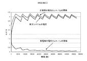
組み立て後に、システムは、添付図2に示されたように、クロノポテンショメトリーによる充電と、それに続く2時間の緩和期間の段階を含む本発明による形成サイクルにしたがって充電され、電圧と電極の電位(ボルト)は、時間(秒)の関数である。充電(37.2mA/gで)/自己放電のサイクルが関係する。サイクルの終わりのシステムの電圧は、4.2Vであった。 After assembly, the system is charged according to the formation cycle according to the present invention, which includes a chronopotentiometric charge followed by a 2-hour relaxation period step, as shown in the attached FIG. Volts) is a function of time (seconds). Charge (at 37.2 mA / g) / self-discharge cycle is involved. The voltage of the system at the end of the cycle was 4.2V.
負電極の特性は、その電位が、充電/自己放電サイクルの終了後にLi+/Liに対して0.1Vになるように選択され、これは、段階2のグラファイト内へのリチウムのインターカレーションにおおよそ対応する。
The characteristics of the negative electrode were selected so that its potential would be 0.1 V with respect to Li + / Li after the end of the charge / self-discharge cycle, which is the intercalation of lithium into the
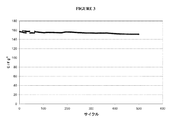
次に、±0.65A/gの定電流サイクルが、システムに対して、周囲温度でUmax=4.2VとUmin=1.5Vの間で実行された。定電流サイクルは、システムの充電及び放電に対応する。 Next, a constant current cycle of ± 0.65 A / g was performed between U max = 4.2 V and U min = 1.5 V at ambient temperature for the system. A constant current cycle corresponds to charging and discharging of the system.
このサイクルの結果は、添付図3に示され、重量容量(F.g−1)は、サイクル数の関数として表される。添付図4は、2つの電極の電位(V)と電圧(V)の変化を、第1のサイクル中と500サイクル後の時間(秒)の関数として示す。 The result of this cycle is shown in the attached FIG. 3, where the weight capacity (F.g −1 ) is expressed as a function of the number of cycles. FIG. 4 shows the change in potential (V) and voltage (V) of the two electrodes as a function of time (seconds) during the first cycle and after 500 cycles.
500サイクル後に2電極システムの自己放電も測定した。次に、電圧を30分間4.2Vに維持した後で自己放電を記録する(添付図5において電圧(V)は時間(時間)の関数である)。 The self-discharge of the two-electrode system was also measured after 500 cycles. Next, the self-discharge is recorded after maintaining the voltage at 4.2 V for 30 minutes (in FIG. 5, the voltage (V) is a function of time).
システムの形成サイクル後の性能を下の表2に示す。 The performance after the system formation cycle is shown in Table 2 below.
比較例1:
本発明によらない対称スーパーキャパシタを以下の方法で作成した。
Comparative Example 1:
A symmetric supercapacitor not according to the present invention was prepared by the following method.
−正電極:80重量%の多孔質活性炭(比表面積(SBET)=1670m2/g)、10重量%のPVDF、及び10重量%のカーボンブラック。この複合電極材料を厚さ30μmのアルミニウム集電材上に被覆した。被覆の厚さ:100μm。 -Positive electrode: 80 wt% porous activated carbon (specific surface area (SBET) = 1670 m < 2 > / g), 10 wt% PVDF, and 10 wt% carbon black. This composite electrode material was coated on an aluminum current collector with a thickness of 30 μm. Coating thickness: 100 μm.
−負電極:正電極と同一:80重量%の多孔質活性炭(比表面積(SBET)=1670m2/g)、10重量%のPVDF、及び10重量%のカーボンブラック。この複合電極材料を厚さ30μmを有するアルミニウム集電材上に被覆した。被覆の厚さ:100μm。 Negative electrode: Same as positive electrode: 80% by weight of porous activated carbon (specific surface area (SBET) = 1670 m 2 / g), 10% by weight of PVDF, and 10% by weight of carbon black. This composite electrode material was coated on an aluminum current collector having a thickness of 30 μm. Coating thickness: 100 μm.
この場合、2つの電極が実施例1の正電極と同一であることに注意されたい。 Note that in this case, the two electrodes are identical to the positive electrode of Example 1.
−使用電解質:1:1(v/v)EC/DMC混合物中の2モル/lのLiTFSI。 -Electrolyte used: 2 mol / l LiTFSI in a 1: 1 (v / v) EC / DMC mixture.
−正電極と負電極の電位の変化を監視するために、Li+/Li基準電極を加えた。 -A Li + / Li reference electrode was added to monitor the change in potential between the positive and negative electrodes.
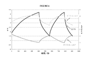
組み立て後、システムに対して、周囲温度でUmax=4.2VとUmin=1.5Vの間で±0.65A/gの定電流サイクルを行った。正電極での電解質の高分解により、定電流サイクル(0.65A/g)を行うことができなかった。添付図6に示したように、正電極の電位は、Li+/Liに対して5Vを超え、ここで電圧と電極の電位(ボルト)は、時間(秒)の関数である。 After assembly, the system was subjected to a constant current cycle of ± 0.65 A / g between U max = 4.2 V and U min = 1.5 V at ambient temperature. The constant current cycle (0.65 A / g) could not be performed due to the high decomposition of the electrolyte at the positive electrode. As shown in FIG. 6, the potential of the positive electrode exceeds 5V with respect to Li + / Li, where the voltage and electrode potential (volts) are a function of time (seconds).
システムの性能を下の表2に示す。 System performance is shown in Table 2 below.
比較例2:
本発明によらない対称スーパーキャパシタを、比較例1で述べた方法にしたがって下記の方法で作成した。
Comparative Example 2:
A symmetric supercapacitor not according to the present invention was prepared according to the method described in Comparative Example 1 by the following method.
−正電極:80重量%の多孔質活性炭(比表面積(SBET)=1670m2/g)、10重量%のPVDF、及び10重量%のカーボンブラック。この複合電極材料を厚さ30μmを有するアルミニウム集電材上に被覆した。被覆の厚さ:100μm。 -Positive electrode: 80 wt% porous activated carbon (specific surface area (SBET) = 1670 m < 2 > / g), 10 wt% PVDF, and 10 wt% carbon black. This composite electrode material was coated on an aluminum current collector having a thickness of 30 μm. Coating thickness: 100 μm.
負電極:正電極と同一:80重量%の多孔質活性炭(比表面積(SBET)=1670m2/g)、10重量%のPVDF、及び10重量%のカーボンブラック。この複合電極材料を厚さ30μmを有するアルミニウム集電材に被覆した。被覆の厚さ:100μm。 Negative electrode: Same as the positive electrode: 80% by weight of porous activated carbon (specific surface area (SBET) = 1670 m 2 / g), 10% by weight PVDF, and 10% by weight carbon black. This composite electrode material was coated on an aluminum current collector having a thickness of 30 μm. Coating thickness: 100 μm.
−使用電解質:1:1(v/v)EC/DMC混合物中の2モル/lのLiTFSI。 -Electrolyte used: 2 mol / l LiTFSI in a 1: 1 (v / v) EC / DMC mixture.
−正電極と負電極の電位の変化を監視するために、Li+/Li基準電極を追加した。 -A Li + / Li reference electrode was added to monitor the change in potential between the positive and negative electrodes.
組み立て後、システムに周囲温度でUmax=2.5VとUmin=0Vの間で±0.65A/gの定電流サイクルを実行した。結果は添付図7に示され、重量容量(F/g)をサイクル数(最も上の曲線)の関数としてプロットした。 After assembly, the system was subjected to a constant current cycle of ± 0.65 A / g between U max = 2.5 V and U min = 0 V at ambient temperature. The results are shown in the attached FIG. 7, where weight capacity (F / g) is plotted as a function of cycle number (top curve).
システムの性能を下の表2に示す。 System performance is shown in Table 2 below.
比較例3:
この例では、本発明によらない比較例2のものと同一の対称スーパーキャパシタを作成したが、電解質を1:1(v/v)EC/DMC混合物中で1.6モル/lの(LiTFSI+1mol%のLiPF6)と置き換えた。電圧は、やはり2.5Vに制限された。周囲温度でシステムに対して±0.65A/gの定電流サイクルを実行した。結果を図7に示す(中間の曲線)。
Comparative Example 3:
In this example, a symmetric supercapacitor identical to that of Comparative Example 2 that was not in accordance with the present invention was made, but the electrolyte was 1.6 mol / l (LiTFSI + 1 mol in a 1: 1 (v / v) EC / DMC mixture. % LiPF 6 ). The voltage was again limited to 2.5V. A constant current cycle of ± 0.65 A / g was performed on the system at ambient temperature. The results are shown in FIG. 7 (intermediate curve).
システムの性能を下の表2に示す。 System performance is shown in Table 2 below.
比較例4:
この例では、本発明によらない比較例2のものと同一の対称スーパーキャパシタを作成したが、電解質を1:1 EC/DMC混合物中の2モル/lの(LiTFSI+1mol%のLiPF6)と置き換えた。電圧は、やはり2.5Vに制限された。周囲温度でシステムに対して±0.65A/gの定電流サイクルを実行した。結果を添付図7に示す(一番下の曲線)。
Comparative Example 4:
In this example, a symmetric supercapacitor identical to that of Comparative Example 2 that was not in accordance with the invention was made, but the electrolyte was replaced with 2 mol / l (LiTFSI + 1 mol% LiPF 6 ) in a 1: 1 EC / DMC mixture. It was. The voltage was again limited to 2.5V. A constant current cycle of ± 0.65 A / g was performed on the system at ambient temperature. The results are shown in FIG. 7 (bottom curve).
システムの性能を下の表2に示す。 System performance is shown in Table 2 below.
比較例5:
この例では、本発明によらない比較例2のものと同一の対称スーパーキャパシタを作成したが、電解質をアセトニトリル中の1モル/lのTEABF4と置き換えた。
Comparative Example 5:
In this example, a symmetric supercapacitor identical to that of Comparative Example 2 not according to the invention was made, but the electrolyte was replaced with 1 mol / l TEABF 4 in acetonitrile.
組み立て後に、システムは、電圧を2.5ボルトに制限しながら充電された。周囲温度でシステムに対して±0.65A/gの定電流サイクルを実行した。 After assembly, the system was charged while limiting the voltage to 2.5 volts. A constant current cycle of ± 0.65 A / g was performed on the system at ambient temperature.
システムの性能を下の表2に示す。 System performance is shown in Table 2 below.
比較例6:
本発明によらない複合スーパーキャパシタを以下の方法で作成した。
Comparative Example 6:
A composite supercapacitor not according to the present invention was prepared by the following method.
−正電極:80重量%の多孔質活性炭(比表面積(SBET)=1670m2/g)、10重量%のPVDF、及び10重量%のカーボンブラック。この複合電極材料を厚さ30μmを有するアルミニウム集電材上に被覆した。被覆の厚さ:100μm。 -Positive electrode: 80 wt% porous activated carbon (specific surface area (SBET) = 1670 m < 2 > / g), 10 wt% PVDF, and 10 wt% carbon black. This composite electrode material was coated on an aluminum current collector having a thickness of 30 μm. Coating thickness: 100 μm.
−負電極:Timcalより商標SLP30で販売されている91重量%のグラファイト、8重量%のPVDF、及び1重量%のカーボンブラック。この複合電極材料を銅集電材上に被覆した。被覆の厚さ:50μm。 -Negative electrode: 91 wt% graphite, 8 wt% PVDF, and 1 wt% carbon black sold under the trademark SLP30 by Timcal. This composite electrode material was coated on a copper current collector. Coating thickness: 50 μm.
正電極と負電極が、実施例1のものと同一であることに注意されたい。 Note that the positive and negative electrodes are the same as in Example 1.
−使用電解質:1:1(v/v)EC/DMC混合物中の2モル/lのLiTFSI+1%のLiPF6。
- Use electrolyte: 1: 1 (v / v ) EC /
−正電極と負電極の電位の変化を監視するために、Li+/Li基準電極を追加した。 -A Li + / Li reference electrode was added to monitor the change in potential between the positive and negative electrodes.
組み立て後、本発明によらない形成サイクルは、4.4Vまでの直接充電と、その後の2時間の自己放電期間からなる。電極の電圧と電位(V)の変化を、形成サイクル中の時間(秒)の関数として添付図8に示す。 After assembly, the formation cycle not according to the invention consists of a direct charge up to 4.4V followed by a self-discharge period of 2 hours. The changes in electrode voltage and potential (V) are shown in FIG. 8 as a function of time (seconds) during the formation cycle.
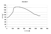
定電流サイクルは、システムに対して、周囲温度でUmax=4.4VとUmin=1.5Vの間で±0.65A/gで実行された。定電流サイクルの結果が添付図9に示され、図では、重量容量(F.g−1)は、サイクル数の関数として表される。 A constant current cycle was performed for the system at ± 0.65 A / g between U max = 4.4 V and U min = 1.5 V at ambient temperature. The result of the constant current cycle is shown in the attached FIG. 9, where the weight capacity (F.g −1 ) is expressed as a function of the number of cycles.
システムの形成サイクル後の性能を下の表2に示す。 The performance after the system formation cycle is shown in Table 2 below.
本発明による実施例2
本発明による複合スーパーキャパシタを以下の方法で作成した。
Example 2 according to the invention
A composite supercapacitor according to the present invention was prepared by the following method.
−正電極:80重量%の多孔質活性炭(比表面積(SBET)=1670m2/g)、10重量%のPVDF、及び10重量%のカーボンブラック。この複合電極材料を厚さ30μmを有するアルミニウム集電材上に被覆した。被覆の厚さ:100μm。 -Positive electrode: 80 wt% porous activated carbon (specific surface area (SBET) = 1670 m < 2 > / g), 10 wt% PVDF, and 10 wt% carbon black. This composite electrode material was coated on an aluminum current collector having a thickness of 30 μm. Coating thickness: 100 μm.
−負電極:Timcalにより商標SLP30で販売されている91重量%のグラファイト、8重量%のPVDF、及び1重量%のカーボンブラック。この複合電極材料を銅の集電材上に被覆した。被覆の厚さ:50μm。 -Negative electrode: 91 wt% graphite, 8 wt% PVDF, and 1 wt% carbon black sold under the trademark SLP30 by Timcal. This composite electrode material was coated on a copper current collector. Coating thickness: 50 μm.
正電極と負電極が、実施例1のものと同一であり、かつ実施例1とは対照的に、システム内にリチウム金属で作成された基準電極がないことに注意されたい。 Note that the positive and negative electrodes are the same as in Example 1 and, in contrast to Example 1, there is no reference electrode made of lithium metal in the system.
−使用電解質:1:1(v/v)EC/DMC混合物中の2モル/l LiTFSI+1mol% LiPF6。 - Use electrolyte: 1: 1 (v / v ) EC / 2 mol / l of DMC mixture LiTFSI + 1mol% LiPF 6.
組み立て後に、システムは、添付図2に示されたように、クロノポテンショメトリーによる充電の段階と、その後の2時間の緩和期間の段階とを含む本発明による形成サイクルによって充電され、電圧(ボルト)は、時間(秒)の関数である。充電(37.2mA/gでの)/自己放電のサイクルは重要である。システムの最大電圧は、4.4Vであった。 After assembly, the system is charged by a forming cycle according to the present invention comprising a chronopotentiometric charging phase followed by a 2-hour relaxation phase phase, as shown in FIG. Is a function of time (seconds). The charge (at 37.2 mA / g) / self-discharge cycle is important. The maximum voltage of the system was 4.4V.
形成サイクル中の時間(秒)の関数としての電圧(V)の変化を、添付図10に示す。 The change in voltage (V) as a function of time (seconds) during the formation cycle is shown in FIG.
システムに対して、周囲温度で、Umax=4.4VとUmin=1.5Vの間で±0.65A/gの定電流サイクルを実行した。このサイクルの結果を添付図11に示し、重量容量(F.g−1)をサイクル数の関数として表す。 The system was subjected to a constant current cycle of ± 0.65 A / g between U max = 4.4 V and U min = 1.5 V at ambient temperature. The results of this cycle are shown in FIG. 11 where the weight capacity (F.g −1 ) is expressed as a function of the number of cycles.
システムの形成サイクル後の性能を下の表2に示す。 The performance after the system formation cycle is shown in Table 2 below.
上記の例で作成された様々なシステムの性能を下の表2に示す。 The performance of the various systems created in the above example is shown in Table 2 below.
これらの組み合わせた結果から、本発明によるスーパーキャパシタが、他のものより高い重量容量を得ることを可能することが分かる(実施例1及び2を比較例1〜5と比較することにより)。更に、これらのスーパーキャパシタは、より高い電圧(4.2V)で動作することができる。これらの2つの要素により、これらのスーパーキャパシタのエネルギー密度をかなり高める(5〜10倍)ことができる。したがって、これらのスーパーキャパシタは、同じサイズの場合に、より大きい電力を提供することができ、この理由のため特に好都合である。 From these combined results, it can be seen that the supercapacitor according to the present invention can obtain a higher weight capacity than others (by comparing Examples 1 and 2 with Comparative Examples 1-5). Furthermore, these supercapacitors can operate at higher voltages (4.2V). These two factors can significantly increase (5 to 10 times) the energy density of these supercapacitors. Thus, these supercapacitors can provide more power for the same size and are particularly advantageous for this reason.
更に、これらの複合スーパーキャパシタは、その重量容量(及び、したがってそれらのエネルギー密度)が、少なくとも500サイクルの間、比較的一定のままなので適切に経年変化し、これは、同じ電解質の対称スーパーキャパシタには当てはまらない。 In addition, these composite supercapacitors are adequately aged because their weight capacity (and therefore their energy density) remains relatively constant for at least 500 cycles, which is a symmetrical supercapacitor of the same electrolyte. Is not true.
最大電圧が実施例1より実施例2の方が高いので、初期容量も実施例1より実施例2の方が高い。他方、電解質へのLiPF6の追加が僅かにもかかわらず、恐らくアルミニウムの腐食のために、サイクル中の容量の低下が、実施例2の場合の方が大きいことに注意されたい。 Since the maximum voltage is higher in the second embodiment than in the first embodiment, the initial capacity is also higher in the second embodiment than in the first embodiment. On the other hand, note that the capacity loss during cycling is greater in the case of Example 2, possibly due to the corrosion of aluminum, despite the slight addition of LiPF 6 to the electrolyte.
更に、段階f)で述べた形成サイクルにより、時間の経過によるスーパーキャパシタの安定性を保証し(比較例6を参照して分かるように、他の充電プロセスと異なる)、エネルギー密度が高く信頼性が高いスーパーキャパシタを得ることができることに注意されたい。 Furthermore, the formation cycle described in step f) ensures the supercapacitor stability over time (different from other charging processes, as can be seen with reference to Comparative Example 6), and has high energy density and reliability. Note that high supercapacitors can be obtained.
更に、複合スーパーキャパシタの良好な動作を可能にする電解質の選択は、当業者にとって当然の選択ではない。その理由は、そのような電解質が、対称スーパーキャパシタに最適でないことがはっきりしているからである。比較例2〜4の重量容量とエネルギー密度は、アセトニトリル中の典型的な従来の電解質1モル/l TEABF4で得られるものより低い(比較例5)。
Furthermore, the choice of electrolyte that allows good operation of the composite supercapacitor is not a natural choice for those skilled in the art. The reason is that it is clear that such electrolytes are not optimal for symmetrical supercapacitors. The weight capacity and energy density of Comparative Examples 2-4 are lower than those obtained with a typical
したがって、本発明により、動作電圧を高め、最新技術の対称スーパーキャパシタより高いエネルギー密度を提供することを可能にする複合スーパーキャパシタを得ることができる。 Thus, the present invention can provide a composite supercapacitor that increases the operating voltage and makes it possible to provide a higher energy density than state-of-the-art symmetric supercapacitors.
Claims (21)
a)前記第1の充電段階の前の前記液体電解質中のイオンリチウムの濃度が、1.6モル/l以上であり、
b)前記液体電解質の前記リチウム塩が、リチウムビス(フルオロスルホニル)イミド(LiFSI)やリチウムビス(ペンタフルオロエチルスルホニル)イミド(LiBETI)などのリチウムビス(トリフルオロメタンスルホニル)イミド(LiTFSI)及びその誘導体から選択された少なくとも50重量%の塩を含み、
c)前記液体電解質の溶媒が、エチレンカーボネート(EC)とプロピレンカーボネート(PC)から選択された環式アルキルカーボネート、ジメチルカーボネート(DMC)、ジエチルカーボネート(DEC)及びメチルイソプロピルカーボネート(MiPC)から選択された非環式アルキルカーボネート、ラクトン、エステル、オキソラン(oxalanes)、及びこれらの混合物から選択された少なくとも80体積%の溶媒を含み、前記溶媒が、少なくとも20体積%のエチレンカーボネートを含み、
d)前記正電極の前記多孔性カーボン系材料が、孔の平均寸法が0.7nmより大きくかつ比表面積が約700m2/g(B.E.T.法)を超える材料から選択され、
e)前記負電極の前記非多孔性カーボン系材料が、前記リチウムイオンを挿入することができかつ150m2/g以下の比表面積を有する材料から選択され、
f)組み立て段階の後で、前記スーパーキャパシタの充電が、4〜5ボルトの最大電圧(Umax)と10mA/g〜400mA/gの電流密度の幾つかの連続充電段階で実行され、各充電段階が、その後の充電段階から、5mA/g未満の電流密度の自己放電又は放電の中間段階によって分離された方法。 In a method of making a composite supercapacitor without using a lithium metal electrode , at least assembling a negative electrode using at least one non-porous carbon-based material and a positive electrode using at least one porous carbon-based material The electrodes are separated from each other by a separator impregnated with a liquid electrolyte comprising at least one lithium salt in a solution of at least one solvent, and then at least one first charging stage. A method comprising:
a) the concentration of ionic lithium in the liquid electrolyte before the first charging stage is 1.6 mol / l or more;
b) The lithium salt of the liquid electrolyte is lithium bis (trifluoromethanesulfonyl) imide (LiTFSI) such as lithium bis (fluorosulfonyl) imide (LiFSI) or lithium bis (pentafluoroethylsulfonyl) imide (LiBETI) and its derivatives. At least 50% by weight of a salt selected from
c) The solvent of the liquid electrolyte, ethylene carbonate (EC) propylene carbonate (PC) is selected from the cyclic alkyl carbonate Natick bets, dimethyl carbonate (DMC), diethylcarbonate (DEC) and methyl isopropyl carbonate (MIPC) acyclic alkyl carbonate is selected, include lactones, esters, oxolane (oxalanes), and at least 80 volume percent of solvent selected from these mixtures, wherein the solvent comprises at least 20 volume% of ethylene carbonate,
d) the porous carbon-based material of the positive electrode is selected from materials having an average pore size greater than 0.7 nm and a specific surface area greater than about 700 m 2 / g (BET method);
e) the non-porous carbon-based material of the negative electrode is selected from materials capable of inserting lithium ions and having a specific surface area of 150 m 2 / g or less;
f) After the assembly stage, the charging of the supercapacitor is carried out in several successive charging stages with a maximum voltage (U max ) of 4-5 volts and a current density of 10 mA / g-400 mA / g, A method wherein the stage is separated from the subsequent charging stage by a self-discharge or intermediate stage of discharge with a current density of less than 5 mA / g.
i)LiTFSI−EC/DMC(1/1;v/v)混合物
ii)LiFSI−EC/DMC(1/1;v/v)混合物
iii)LiBETI−EC/DMC(1/1;v/v)混合物
iv)LiTFSI−EC/EB/DMC(1/1/3;v/v/v)混合物
v)LiTFSI−EC/MiPC/DMC(2/1/3/;v/v/v)混合物
vi)LiTFSI−EC/DME(1/2;v/v)混合物
のリチウム塩/溶媒対から選択された、請求項1又は2に記載の方法。 The liquid electrolyte is
i) LiTFSI-EC / DMC (1/1; v / v) mixture ii) LiFSI-EC / DMC (1/1; v / v) mixture iii) LiBETI-EC / DMC (1/1; v / v) Mixture iv) LiTFSI-EC / EB / DMC (1/1/3; v / v / v) Mixture v) LiTFSI-EC / MiPC / DMC (2/1/3 /; v / v / v) Mixture vi) 3. A process according to claim 1 or 2 selected from lithium salt / solvent pairs of LiTFSI-EC / DME (1/2; v / v) mixtures.
1)10〜400mA/gの電流密度で、4.0V〜5Vの電圧Umax1まで充電し、次に1時間の最小持続時間の緩和期間を行う副段階1と、
2)10〜400mA/gの電流密度で電圧Umax2>Umax1かつ≦5Vまで充電し、次に1時間の最小持続時間の緩和期間を行う副段階2と、
3)10〜400mA/gの電流密度で電圧Umax3>Umax2かつ≦5Vまで充電し、次に1時間の最小持続時間の緩和期間を行う副段階3と、
4)10〜400mA/gの電流密度で電圧Umax4>Umax3かつ≦5Vまで充電し、次に1時間の最小持続時間の緩和期間を行う副段階4と、
5)10〜400mA/gの電流密度で、電圧Umax5>Umax4かつ≦5Vまで充電し、次に1時間の最小持続時間の緩和期間を続ける副段階5とを含む、請求項1〜20のいずれか一項に記載の方法。 Stage f) is the following sub-stage 1) Sub-stage 1 charging at a current density of 10 to 400 mA / g to a voltage U max1 of 4.0 V to 5 V, followed by a minimum duration relaxation period of 1 hour. When,
2) Sub-stage 2 charging to a voltage U max2 > U max1 and ≦ 5 V at a current density of 10 to 400 mA / g, followed by a minimum duration relaxation period of 1 hour;
3) Sub-stage 3 charging at a current density of 10 to 400 mA / g to a voltage U max3 > U max2 and ≦ 5 V, followed by a minimum duration relaxation period of 1 hour;
4) Sub-stage 4 charging at a current density of 10-400 mA / g to a voltage U max4 > U max3 and ≦ 5 V, followed by a minimum duration relaxation period of 1 hour;
5) at a current density of 10~400mA / g, and a voltage U max5> U max4 and charged to ≦ 5V, substep 5 next continue relaxation period of a minimum duration of 1 hour, according to claim 20 The method as described in any one of .
Applications Claiming Priority (3)
| Application Number | Priority Date | Filing Date | Title |
|---|---|---|---|
| FR1155048 | 2011-06-09 | ||
| FR1155048 | 2011-06-09 | ||
| PCT/FR2012/050837 WO2012172211A1 (en) | 2011-06-09 | 2012-04-17 | Method for assembling a hybrid lithium supercapacitor |
Publications (3)
| Publication Number | Publication Date |
|---|---|
| JP2014520395A JP2014520395A (en) | 2014-08-21 |
| JP2014520395A5 JP2014520395A5 (en) | 2016-09-01 |
| JP6067003B2 true JP6067003B2 (en) | 2017-01-25 |
Family
ID=46208615
Family Applications (1)
| Application Number | Title | Priority Date | Filing Date |
|---|---|---|---|
| JP2014514126A Expired - Fee Related JP6067003B2 (en) | 2011-06-09 | 2012-04-17 | Method for assembling a composite electrochemical system |
Country Status (13)
| Country | Link |
|---|---|
| US (1) | US9136066B2 (en) |
| EP (1) | EP2718944B1 (en) |
| JP (1) | JP6067003B2 (en) |
| KR (1) | KR101985789B1 (en) |
| CN (1) | CN103733290B (en) |
| AU (1) | AU2012270250B2 (en) |
| BR (1) | BR112013031315A2 (en) |
| CA (1) | CA2835124C (en) |
| ES (1) | ES2641533T3 (en) |
| IL (1) | IL229655A (en) |
| RU (1) | RU2591846C2 (en) |
| UA (1) | UA110650C2 (en) |
| WO (1) | WO2012172211A1 (en) |
Families Citing this family (6)
| Publication number | Priority date | Publication date | Assignee | Title |
|---|---|---|---|---|
| JP2014225574A (en) * | 2013-05-16 | 2014-12-04 | 住友電気工業株式会社 | Capacitor and charge and discharge method thereof |
| US10756390B2 (en) * | 2014-11-20 | 2020-08-25 | Ses Holdings Pte. Ltd. | Concentrated electrolyte solution |
| WO2017131016A1 (en) * | 2016-01-29 | 2017-08-03 | 日本ケミコン株式会社 | Electrode, capacitor in which electrode is used, and method for manufacturing electrode |
| JP2017139435A (en) * | 2016-01-29 | 2017-08-10 | 日本ケミコン株式会社 | Electrode, capacitor using the same, and electrode manufacturing method |
| WO2017212596A1 (en) * | 2016-06-08 | 2017-12-14 | 日産自動車株式会社 | Nonaqueous electrolyte secondary battery |
| US10600583B1 (en) | 2018-08-30 | 2020-03-24 | King Saud University | Method of making a porous nitrogen-doped carbon electrode from biomass |
Family Cites Families (15)
| Publication number | Priority date | Publication date | Assignee | Title |
|---|---|---|---|---|
| JP4618929B2 (en) * | 2000-05-09 | 2011-01-26 | 三菱化学株式会社 | Activated carbon for electric double layer capacitors |
| CA2327370A1 (en) * | 2000-12-05 | 2002-06-05 | Hydro-Quebec | New method of manufacturing pure li4ti5o12 from the ternary compound tix-liy-carbon: effect of carbon on the synthesis and conductivity of the electrode |
| EP1400996B1 (en) | 2001-06-29 | 2011-05-11 | Fuji Jukogyo Kabushiki Kaisha | Organic electrolyte capacitor |
| US7049032B2 (en) * | 2001-07-25 | 2006-05-23 | Asahi Glass Company, Limited | Secondary power source |
| KR100534845B1 (en) * | 2003-12-30 | 2005-12-08 | 현대자동차주식회사 | Method for Manufacturing Nano-structured Electrode of Metal Oxide |
| JP2006024785A (en) * | 2004-07-08 | 2006-01-26 | Tomiyama Pure Chemical Industries Ltd | Electric double layer capacitor and nonaqueous electrolytic solution therefor |
| KR20070121034A (en) * | 2005-04-19 | 2007-12-26 | 마츠시타 덴끼 산교 가부시키가이샤 | Nonaqueous electrolyte solution, electrochemical energy storage device using same, and nonaqueous electrolyte secondary battery |
| RU2391732C2 (en) * | 2005-06-24 | 2010-06-10 | ЮНИВЕРСАЛ СУПЕРКАПАСИТОРЗ ЭлЭлСи | Heterogeneous electrochemical supercapacitor and method of manufacturing |
| JP2007299569A (en) * | 2006-04-28 | 2007-11-15 | Matsushita Electric Ind Co Ltd | Electrochemical energy storage device |
| JP2008177263A (en) | 2007-01-17 | 2008-07-31 | Sanyo Electric Co Ltd | Active carbon electrode and its manufacturing method, electric double-layer capacitor, and hybrid capacitor |
| JP4918418B2 (en) * | 2007-06-13 | 2012-04-18 | アドバンスト・キャパシタ・テクノロジーズ株式会社 | Lithium ion pre-doping method and method for producing lithium ion capacitor storage element |
| CN100595965C (en) * | 2007-06-28 | 2010-03-24 | 比亚迪股份有限公司 | Li-ion secondary battery formation method |
| FR2935547B1 (en) | 2008-08-29 | 2011-03-25 | Commissariat Energie Atomique | IONIC LIQUID ELECTROLYTES AND ELECTROCHEMICAL DEVICES SUCH AS ACCUMULATORS COMPRISING SAME. |
| CN102171869B (en) * | 2008-11-10 | 2016-01-20 | 株式会社爱考斯研究 | Anode of secondary cell and adopt the secondary cell of this positive pole and collector body and adopt the battery of this collector body |
| JP2010205846A (en) * | 2009-03-02 | 2010-09-16 | Asahi Kasei Corp | Nonaqueous lithium type electricity storage element |
-
2012
- 2012-04-17 CA CA2835124A patent/CA2835124C/en not_active Expired - Fee Related
- 2012-04-17 AU AU2012270250A patent/AU2012270250B2/en not_active Ceased
- 2012-04-17 JP JP2014514126A patent/JP6067003B2/en not_active Expired - Fee Related
- 2012-04-17 KR KR1020147000680A patent/KR101985789B1/en active IP Right Grant
- 2012-04-17 US US14/119,570 patent/US9136066B2/en not_active Expired - Fee Related
- 2012-04-17 UA UAA201400113A patent/UA110650C2/en unknown
- 2012-04-17 RU RU2013158932/07A patent/RU2591846C2/en not_active IP Right Cessation
- 2012-04-17 ES ES12725858.0T patent/ES2641533T3/en active Active
- 2012-04-17 CN CN201280028163.XA patent/CN103733290B/en not_active Expired - Fee Related
- 2012-04-17 WO PCT/FR2012/050837 patent/WO2012172211A1/en active Application Filing
- 2012-04-17 BR BR112013031315A patent/BR112013031315A2/en active Search and Examination
- 2012-04-17 EP EP12725858.0A patent/EP2718944B1/en not_active Not-in-force
-
2013
- 2013-11-27 IL IL229655A patent/IL229655A/en active IP Right Grant
Also Published As
| Publication number | Publication date |
|---|---|
| EP2718944B1 (en) | 2017-08-02 |
| AU2012270250B2 (en) | 2016-07-21 |
| KR20140073479A (en) | 2014-06-16 |
| US20140325807A1 (en) | 2014-11-06 |
| AU2012270250A1 (en) | 2013-12-12 |
| EP2718944A1 (en) | 2014-04-16 |
| WO2012172211A1 (en) | 2012-12-20 |
| CN103733290B (en) | 2017-06-30 |
| ES2641533T3 (en) | 2017-11-10 |
| RU2013158932A (en) | 2015-07-20 |
| UA110650C2 (en) | 2016-01-25 |
| JP2014520395A (en) | 2014-08-21 |
| BR112013031315A2 (en) | 2016-11-29 |
| CA2835124A1 (en) | 2012-12-20 |
| IL229655A (en) | 2017-06-29 |
| IL229655A0 (en) | 2014-01-30 |
| CA2835124C (en) | 2019-06-25 |
| CN103733290A (en) | 2014-04-16 |
| KR101985789B1 (en) | 2019-06-04 |
| US9136066B2 (en) | 2015-09-15 |
| RU2591846C2 (en) | 2016-07-20 |
Similar Documents
| Publication | Publication Date | Title |
|---|---|---|
| EP2989649B1 (en) | Methods for solid electrolyte interphase formation and anode pre-lithiation of lithium ion capacitors | |
| Kumagai et al. | Cycle performance of lithium-ion capacitors using graphite negative electrodes at different pre-lithiation levels | |
| JP6067003B2 (en) | Method for assembling a composite electrochemical system | |
| JP2008294314A (en) | Capacitor | |
| EP2945211B1 (en) | Lithium titanate oxide as negative electrode in li-ion cells | |
| EP2577776A1 (en) | High energy density electrochemical capacitors | |
| KR20170134335A (en) | Separator for Hybrid Capacitors and Hybrid Capacitors | |
| JP2014520395A5 (en) | ||
| KR20040081043A (en) | Lithium Battery | |
| KR101948804B1 (en) | Graphite anode with improved lithium pre-doping speed and lithium ion capacitor employing the same | |
| JP6623538B2 (en) | Hybrid capacitor separator and hybrid capacitor | |
| JP2008034304A (en) | Energy storing device | |
| JP4863001B2 (en) | Electric storage device and manufacturing method thereof | |
| JP2000306609A (en) | Secondary power supply | |
| JP5052145B2 (en) | Method for producing lithium ion secondary battery | |
| KR100537366B1 (en) | Hybrid capacitor | |
| JP4863000B2 (en) | Electric storage device and manufacturing method thereof | |
| US10096835B2 (en) | Lithium-ion accumulator | |
| JP6605496B2 (en) | Method for manufacturing Li-ion battery cell containing LNMO cathode material | |
| JP6967688B2 (en) | Hybrid capacitor | |
| JP2012114201A (en) | Power storage device | |
| JP2009026508A (en) | Power storage device | |
| JP2009260187A (en) | Electrical storage device | |
| JP2007281287A (en) | Electrical storage device | |
| WO2008041714A1 (en) | Charging device, and its manufacturing method |
Legal Events
| Date | Code | Title | Description |
|---|---|---|---|
| A621 | Written request for application examination |
Free format text: JAPANESE INTERMEDIATE CODE: A621 Effective date: 20150406 |
|
| A977 | Report on retrieval |
Free format text: JAPANESE INTERMEDIATE CODE: A971007 Effective date: 20160120 |
|
| A131 | Notification of reasons for refusal |
Free format text: JAPANESE INTERMEDIATE CODE: A131 Effective date: 20160209 |
|
| A601 | Written request for extension of time |
Free format text: JAPANESE INTERMEDIATE CODE: A601 Effective date: 20160426 |
|
| A524 | Written submission of copy of amendment under article 19 pct |
Free format text: JAPANESE INTERMEDIATE CODE: A524 Effective date: 20160708 |
|
| TRDD | Decision of grant or rejection written | ||
| A01 | Written decision to grant a patent or to grant a registration (utility model) |
Free format text: JAPANESE INTERMEDIATE CODE: A01 Effective date: 20161129 |
|
| A61 | First payment of annual fees (during grant procedure) |
Free format text: JAPANESE INTERMEDIATE CODE: A61 Effective date: 20161220 |
|
| R150 | Certificate of patent or registration of utility model |
Ref document number: 6067003 Country of ref document: JP Free format text: JAPANESE INTERMEDIATE CODE: R150 |
|
| R250 | Receipt of annual fees |
Free format text: JAPANESE INTERMEDIATE CODE: R250 |
|
| LAPS | Cancellation because of no payment of annual fees |