JP6066614B2 - Image reading device - Google Patents
Image reading device Download PDFInfo
- Publication number
- JP6066614B2 JP6066614B2 JP2012177087A JP2012177087A JP6066614B2 JP 6066614 B2 JP6066614 B2 JP 6066614B2 JP 2012177087 A JP2012177087 A JP 2012177087A JP 2012177087 A JP2012177087 A JP 2012177087A JP 6066614 B2 JP6066614 B2 JP 6066614B2
- Authority
- JP
- Japan
- Prior art keywords
- image reading
- reading unit
- holding member
- flat cable
- flexible flat
- Prior art date
- Legal status (The legal status is an assumption and is not a legal conclusion. Google has not performed a legal analysis and makes no representation as to the accuracy of the status listed.)
- Active
Links
Images


Classifications
-
- H—ELECTRICITY
- H04—ELECTRIC COMMUNICATION TECHNIQUE
- H04N—PICTORIAL COMMUNICATION, e.g. TELEVISION
- H04N1/00—Scanning, transmission or reproduction of documents or the like, e.g. facsimile transmission; Details thereof
- H04N1/024—Details of scanning heads ; Means for illuminating the original
- H04N1/0249—Arrangements for mounting or supporting elements within a scanning head
-
- H—ELECTRICITY
- H04—ELECTRIC COMMUNICATION TECHNIQUE
- H04N—PICTORIAL COMMUNICATION, e.g. TELEVISION
- H04N1/00—Scanning, transmission or reproduction of documents or the like, e.g. facsimile transmission; Details thereof
- H04N1/0083—Arrangements for transferring signals between different components of the apparatus, e.g. arrangements of signal lines or cables
-
- H—ELECTRICITY
- H04—ELECTRIC COMMUNICATION TECHNIQUE
- H04N—PICTORIAL COMMUNICATION, e.g. TELEVISION
- H04N1/00—Scanning, transmission or reproduction of documents or the like, e.g. facsimile transmission; Details thereof
- H04N1/04—Scanning arrangements, i.e. arrangements for the displacement of active reading or reproducing elements relative to the original or reproducing medium, or vice versa
- H04N1/10—Scanning arrangements, i.e. arrangements for the displacement of active reading or reproducing elements relative to the original or reproducing medium, or vice versa using flat picture-bearing surfaces
- H04N1/1013—Scanning arrangements, i.e. arrangements for the displacement of active reading or reproducing elements relative to the original or reproducing medium, or vice versa using flat picture-bearing surfaces with sub-scanning by translatory movement of at least a part of the main-scanning components
- H04N1/1026—Scanning arrangements, i.e. arrangements for the displacement of active reading or reproducing elements relative to the original or reproducing medium, or vice versa using flat picture-bearing surfaces with sub-scanning by translatory movement of at least a part of the main-scanning components using a belt or cable
-
- H—ELECTRICITY
- H04—ELECTRIC COMMUNICATION TECHNIQUE
- H04N—PICTORIAL COMMUNICATION, e.g. TELEVISION
- H04N1/00—Scanning, transmission or reproduction of documents or the like, e.g. facsimile transmission; Details thereof
- H04N1/04—Scanning arrangements, i.e. arrangements for the displacement of active reading or reproducing elements relative to the original or reproducing medium, or vice versa
- H04N1/10—Scanning arrangements, i.e. arrangements for the displacement of active reading or reproducing elements relative to the original or reproducing medium, or vice versa using flat picture-bearing surfaces
- H04N1/1013—Scanning arrangements, i.e. arrangements for the displacement of active reading or reproducing elements relative to the original or reproducing medium, or vice versa using flat picture-bearing surfaces with sub-scanning by translatory movement of at least a part of the main-scanning components
- H04N1/1035—Scanning arrangements, i.e. arrangements for the displacement of active reading or reproducing elements relative to the original or reproducing medium, or vice versa using flat picture-bearing surfaces with sub-scanning by translatory movement of at least a part of the main-scanning components by other means, e.g. linear motor or hydraulic system
Landscapes
- Engineering & Computer Science (AREA)
- Multimedia (AREA)
- Signal Processing (AREA)
- Facsimile Scanning Arrangements (AREA)
- Optical Systems Of Projection Type Copiers (AREA)
- Electrophotography Configuration And Component (AREA)
Description
本発明はフレキシブルフラットケーブルを用いた画像読取装置に関する。 The present invention relates to an image reading apparatus using a flexible flat cable.
従来から知られている画像読取装置について図9および図10を用いて説明する。 A conventionally known image reading apparatus will be described with reference to FIGS. 9 and 10. FIG.
画像読取装置の枠体901の内部には枠体901内部を往復移動可能である画像読取ユニット902が設けられている。画像読取ユニット902には、CCD等のイメージセンサーが組み込まれたセンサー基板、原稿画像を照らす照明部、原稿からの反射光をイメージセンサーに結像するレンズが設けれられている。そして、画像読取ユニット902は原稿台ガラス903下を移動しながら、原稿台ガラス903上に載置された原稿を読み取る。
An
画像読取ユニット902は枠体901内に配設されたモーターの駆動力によって往復移動する。本明細書では、画像読取ユニット902が往復移動する方向を副走査方向、この副走査方向と直交する方向(画像読取ユニットの長手方向)を主走査方向と呼ぶ。
The
図9において、センサー基板は画像読取ユニット902の右側に設けられている。センサー基板1003およびフレキシブルフラットケーブル904(以下、FFCと呼ぶ)を観察できる視点からの画像読取ユニット902の斜視図を図10に示す。
In FIG. 9, the sensor substrate is provided on the right side of the
画像読取装置は、モーターに制御信号を与えて画像読取ユニット902を移動させたり、画像読取ユニット902から出力された画像信号を処理するためのコントローラー基板(不図示)を備えている。
The image reading apparatus includes a controller board (not shown) for applying a control signal to the motor to move the
そして、コントローラー基板と画像読取ユニット902との間で制御信号および画像信号の通信を行うために、画像読取ユニット902とコントローラ基板はFFC904によって接続されている。FFC904の一方の端部は、画像読取装置902のセンサー基板1003に接続されている。
The
図9において、画像読取ユニット902の左側にFFC904の湾曲部1001を設けると、画像読取ユニット902が往復移動する際にFFC904が座屈することがなくなり、画像読取ユニット902をスムーズに移動させることが可能となる。
In FIG. 9, when the
従来技術では、画像読取ユニット902の底面にFFC904をガイドするためのガイド部1002が設けられている。センサー基板1003に接続されたFFC904の一部が、ガイド部1002により画像読取ユニット902の底面で保持され、FFC904は図9において副走査方向における画像読取ユニット902の左側に案内される。そして、図9において副走査方向における画像読取ユニット902の左側にFFCの湾曲部1001が形成される。
In the prior art, a
しかしながら、上記従来の構成を有する画像読取装置においては、画像読取ユニットの底面に設けられたガイド部にFFCを案内させる構成であったため、画像読取ユニットへのFFCの取付け時や、取外し時の作業性に改善の余地があった。 However, in the image reading apparatus having the above-described conventional configuration, the FFC is guided by the guide portion provided on the bottom surface of the image reading unit. Therefore, the work when the FFC is attached to or removed from the image reading unit. There was room for improvement in sex.
また、FFCの取付作業性が悪いため、FFCをガイド部に案内させる作業の中で、FFCにシワや傷が発生させてしまう可能性があった。このシワや傷は場合、FFCの断線を引き起こす可能性もある。 Further, since the mounting workability of the FFC is poor, there is a possibility that the FFC may be wrinkled or scratched during the work of guiding the FFC to the guide portion. In some cases, the wrinkles and scratches may cause disconnection of the FFC.
本発明は、画像読取ユニットへのフレキシブルフラットケーブルの取付け・取外し作業の作業性を向上させつつ、画像読取領域の内側の原稿台とフレキシブルフラットケーブルとの接触を抑制することを目的とする。An object of the present invention is to suppress contact between a document table inside an image reading area and a flexible flat cable while improving workability of attaching / detaching a flexible flat cable to / from an image reading unit.
本発明は上記目的を達成するための画像読取装置の一態様は、原稿が載置される原稿台と、前記原稿台の下方を移動可能であり、前記原稿台に載置された原稿からの反射光を受光し、画像信号を出力する画像読取ユニットと、前記画像読取ユニットから出力された画像信号を伝送するフレキシブルフラットケーブルと、前記フレキシブルフラットケーブルを保持し、前記画像読取ユニットに着脱可能に取り付けられる保持部材と、前記画像読取ユニットは、前記フレキシブルフラットケーブルが接続される接続部であって、前記画像読取ユニットの読取領域の内側に配置される接続部と、を有し、前記保持部材は画像読取ユニットの画像読取領域の内側と画像読取領域の外側にまたがるように前記画像読取ユニットに装着され、前記画像読取ユニットの移動方向において、前記画像読取ユニットの接続部と、前記画像読取ユニットを挟んだ反対側に、前記フレキシブルフラットケーブルの湾曲部が形成され、前記保持部材は、前記フレキシブルフラットケーブルの前記接続部側を画像読取領域の内側において保持し、前記フレキシブルフラットケーブルの前記湾曲部側を前記画像読取ユニットの読取領域の外側で保持することを特徴とする。According to one aspect of the image reading apparatus for achieving the above object, an original platen on which an original is placed and a lower part of the original table are movable. An image reading unit that receives reflected light and outputs an image signal; a flexible flat cable that transmits an image signal output from the image reading unit; and the flexible flat cable that is held and detachable from the image reading unit A holding member to be attached; and the image reading unit includes a connecting portion to which the flexible flat cable is connected, and a connecting portion disposed inside a reading region of the image reading unit, and the holding member Is mounted on the image reading unit so as to straddle the inside of the image reading area of the image reading unit and the outside of the image reading area. In the moving direction of the knit, a curved portion of the flexible flat cable is formed on a side opposite to the connection portion of the image reading unit and the image reading unit, and the holding member is the connection portion of the flexible flat cable. The side is held inside the image reading area, and the curved portion side of the flexible flat cable is held outside the reading area of the image reading unit.
本発明によれば、画像読取ユニットへのフレキシブルフラットケーブルの取付け・取外し作業の作業性を向上させつつ、画像読取領域の内側の原稿台とフレキシブルフラットケーブルとの接触を抑制することができる。According to the present invention, it is possible to suppress the contact between the document table inside the image reading area and the flexible flat cable while improving the workability of attaching / detaching the flexible flat cable to / from the image reading unit.
本発明にかかる実施形態について図面を用いて説明する。ただし、以下に説明する実施形態は、本発明を具体化した一例であって、本発明の技術的範囲を限定するものではない。 Embodiments according to the present invention will be described with reference to the drawings. However, the embodiment described below is an example embodying the present invention, and does not limit the technical scope of the present invention.
図2、図3および図4を用いて本実施形態に係る画像読取装置202の概略構成について説明する。なお、画像読取装置は実施形態の一例に過ぎず、画像読取装置を備えたファクシミリ装置や複合機などにも本発明を適用することができる。
A schematic configuration of the
図2は自動原稿搬送装置201(以下、ADFと呼ぶ)を備えた画像読取装置202の概略図である。図3は画像読取装置202においてADF201を開いた状態の概略図である。
FIG. 2 is a schematic diagram of an
図2に示すように、画像読取装置202の上方にはADF201が取り付けられている。ADF201は複数枚の原稿を載置可能である給紙トレイ203を有する。給紙トレイ203に載置された原稿は1枚ずつ分離され、画像読取位置に搬送され、排紙トレイに204に排紙される。原稿は、搬送されながら、画像読取位置の下の位置にいる画像読取ユニット401によって読み取られる(以下、流し読みと呼ぶ)。
As shown in FIG. 2, an
図3に示すように、ADF201は画像読取装置202に対して開閉可能である。原稿台301はガラス等の透明部材によって形成されており、ADF201を画像読取装置202に対して開けることにより、原稿台301に、原稿や厚物原稿(たとえば書籍)を載置することができる。ADF201を画像読取装置202に対して閉じることにより、原稿台301上に載置された原稿は、ADF201の底面に設けられた圧板302によって押圧される。画像読取ユニット401は原稿台301の下を副走査方向に移動しながら原稿台301に載置された原稿を読み取る(以下、固定読みと呼ぶ)。
As shown in FIG. 3, the ADF 201 can be opened and closed with respect to the
図4は画像読取装置202の断面図である。画像読取ユニット401は枠体402の内部に配置され、副走査方向403に往復移動可能である。画像読取ユニット401は、画像読取位置の原稿を照明するLED等の照明部、CCD等のイメージセンサー、イメージセンサーが組み込まれたセンサー基板404、および照明部によって照明された原稿からの反射光をイメージセンサに結像する光学レンズなどを有する。センサー基板404は、図4において画像読取ユニット401の副走査方向右側に固定されている。イメージセンサーは照明部によって照明された原稿からの反射光を受光し、画像信号を生成する。画像読取ユニット401は、生成された画像信号を出力する。画像読取装置401は、モーターに制御信号を与えて画像読取ユニット401を移動させたり、画像読取ユニット401から出力された画像情報を処理するためのコントローラー基板(不図示)を備えている。そして、コントローラー基板と画像読取ユニット401との間で制御信号および画像信号の通信を行うために、画像読取ユニット401とコントローラー基板はFFC(フレキシブルフラットケーブル)102によって接続されている。FFC102の一方の端部は、センサー基板404の接続部103に接続されており、他方の端部はコントローラー基板に接続されている。画像読取ユニット401のセンサー基板404から出力される画像情報はFFC102を介してコントローラー基板に伝送され、処理される。
FIG. 4 is a cross-sectional view of the
次に、画像読取ユニット401とFFC102の位置関係について説明する。センサー基板404が、図4において画像読取ユニット401の副走査方向右側に固定されているので、FFC102とセンサー基板404の接続部103も、図4において画像読取ユニット401の副走査方向右側に設けられている。
Next, the positional relationship between the
接続部103に接続されたFFC102は、画像読み取りの妨げにならないように、画像読取ユニット401の底面を通って、副走査方向において画像読取ユニット401の反対側に案内される。さらに、画像読取ユニット401の副走査方向403の往復移動によってFFC102が座屈しないようにするために、FFCに湾曲部106を設ける必要がある。
The
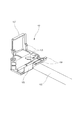
図10に示す従来技術では画像読取ユニットの底面に設けられたガイド部を用いてFFCが画像読取ユニットの底面に取り付けられる。これに対して、本実施形態では、保持部材101を用いてFFC102が画像読取ユニット401に取付けられる。図1は保持部材101の概略図である。
In the prior art shown in FIG. 10, the FFC is attached to the bottom surface of the image reading unit using a guide portion provided on the bottom surface of the image reading unit. On the other hand, in this embodiment, the
FFC102は保持部材101に両面テープ等により取り付けられる。FFC102が取り付けられている保持部材101は、保持部材101に設けられた爪部104とスナップフィット部105によって、画像読取ユニット401に取付けられる。
The
このように簡単に取り付け可能な保持部材101を使用することにより、図10に示す従来の装置を組み立てる際に行っていた画像読取ユニットの底面に設けられたガイド部1002にFFCを案内する作業が不要となる。このため、従来の装置においてFFCをガイド部102に案内させる作業で発生する、FFCにしわができたり、FFCに傷を付けることを抑制することができる。つまり、保持部材101を用いることにより、組み立て作業において、FFCにダメージを与えることを抑制し、かつ画像読取ユニットへFFCを簡単に取り付け可能とすることができる。
By using the holding
図1及び図5を用いて保持部材101の爪部104とスナップフィット部105の位置関係を説明する。図5は画像読取ユニット401に保持部材101を取付ける際の動作を示す図である。
The positional relationship between the
FFC端部108は、画像読取ユニット401の接続部103に接続されるFFC102の端部である。保持部材101の爪部104は、FFC端部108と同一側に設けられている。一方、保持部材101のスナップフィット部105は、爪部104とは反対側に設けられている。爪部104の反対側は、FFCの湾曲部106が設けられる側である。
The
このように爪部104とスナップフィット部105を配置することにより、FFC108が接続部103に接続されている、いないに関わらず、容易に保持部材101の付け外しすることができる。
By disposing the
保持部材101を画像読取装置401に取り付ける際、作業者は、まず、爪部104を画像読取装置401の所定箇所にひっかける。その後、保持部材回動方向501に示されるように、保持部材101を回動させ、スナップフィット部105を画像読取装置401の所定箇所にフィットさせる。これらの作業により保持部材101を画像読取装置401への取り付けることができる。スナップフィット部105がFFCの湾曲部106側に設けられているので、保持部材回動方向501に示されるように保持部材101を回動してもFFCによって引っ張られることがない。
When attaching the holding
保持部材101を画像読取装置401から取り外す際、作業者は、まず、スナップフィット部105を画像読取装置401から外す。その後、保持部材回動方向501に示されるように、保持部材101を回動させた後、爪部104を画像読取装置401から外す。爪部104がFFC端部108と同一側に設けられているので、保持部材101を画像読取装置401から取り外すまで、FFC端部108と画像読取装置401の接続部103との位置関係を維持することができる。つまり、FFC端部108が接続部103に接続されていたとしても、保持部材101を画像読取装置401から取り外すことができる。そして、保持部材101を取り外した後に接続部103からFFC端部108を取り外すことができるので、FFC端部108の取り外しも簡単に行うことができる。さらに、スナップフィット部105を画像読取装置401から取り外す際に使うような大きな力が接続部103にかかるのを可能性を低減することができ、FFC端部108および接続部103が傷つく可能性を低減させることができる。
When removing the holding
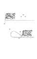
図6は、画像読取装置202の枠体402内に配置されている画像読取装置401に取り付けられた保持部材101を、原稿台301側から見た図である。なお、図6では、FFC102を湾曲部106、保持部材101内の曲げ部605、湾曲以外の部分604のそれぞれに符号をつけている。
FIG. 6 is a view of the holding
図6(B)に示すように、画像読取装置202の枠体402、画像読取ユニット401、FFCと画像読取領域602(すなわち原稿台301の領域)が配置されている。FFCが原稿台301に接触すると、ゴミなどの異物が原稿台301に付着して画質劣化の原因となる。そこで、本実施形態では、図6(A)に示されるように、画像読取領域602内に配置されている画像読取ユニット401の接続部103に接続されたFFCを、主走査方向603において画像読取領域602外に、保持部材101を用いてずらす。主走査方向603は副走査方向403に直交する方向である。具体的には、保持部材101の中でFFCを2回折り曲げることにより、湾曲部側のFFC604が画像読取領域602の外に配置する。接続部側のFFCの位置に対して前記湾曲部側のフレキシブルフラットケーブル106の位置が、主走査方向において所定距離601ずらす。このようにすることにより、保持部材101から出ているFFC(FFC湾曲部106およびFFC湾曲以外の部分604)を画像読取領域602外に配置することができ、FFCが原稿台301に接触することを防ぐことができる。
As shown in FIG. 6B, a
次に、保持部材101に保持部107を設けることの有効性を説明する。図7および図8は保持部107の有無が、画像読取ユニット401が副走査方向403に往復移動がFFC102の屈曲部701へ与える影響を説明するための図である。
Next, the effectiveness of providing the holding
図7に示す本実施形態の保持部材101は原稿台301に向かって伸びる保持部107を有する。画像読取ユニット401の底面からでたFFCは、保持部107によって上方(原稿台301方向)に曲げられる。
The holding
FFCの組立作業時での作業性の視点からは、図8に示すように、保持部107がない保持部材を用いることも可能である。しかし、画像読取ユニットの往復移動に対するFFCの耐久寿命を延ばすために、保持部107を有する保持部材101を用いることが有効である。
From the viewpoint of workability at the time of FFC assembly work, as shown in FIG. 8, it is possible to use a holding member without the holding
図7および図8に示すように、画像読取ユニット401が副走査方向403に往復移動する際、FFCには屈曲部701、801が発生する。図7に示すように、保持部107を設けた場合、屈曲部701の屈曲角度は、屈曲角度702になる。一方、図8に示すように、保持部107を設けない場合、繰り返し屈曲部801の屈曲角度は、屈曲角度802になる。屈曲角度が大きければ画像読取ユニットの往復移動の際に、繰り返し屈曲部に生じる疲労は大きくなる。図7および図8から明らかであるように、屈曲角度702は屈曲角度802よりも小さい。よって、保持部107を設けることにより、屈曲部に生じる疲労を低減させることができ、FFCの耐久寿命を延ばすことができる。
As shown in FIGS. 7 and 8, when the
101 保持部材
102 FFC(フレキシブルフラットケーブル)
103 接続部
104 爪部
105 スナップフィット部
107 保持部
101 holding
103
Claims (8)
前記原稿台の下方を移動可能であり、前記原稿台に載置された原稿からの反射光を受光し、画像信号を出力する画像読取ユニットと、
前記画像読取ユニットから出力された画像信号を伝送するフレキシブルフラットケーブルと、
前記フレキシブルフラットケーブルを保持し、前記画像読取ユニットに着脱可能に取り付けられる保持部材と、
前記画像読取ユニットは、前記フレキシブルフラットケーブルが接続される接続部であって、前記画像読取ユニットの読取領域の内側に配置される接続部と、を有し、
前記保持部材は画像読取ユニットの画像読取領域の内側と画像読取領域の外側にまたがるように前記画像読取ユニットに装着され、前記画像読取ユニットの移動方向において、前記画像読取ユニットの接続部と、前記画像読取ユニットを挟んだ反対側に、前記フレキシブルフラットケーブルの湾曲部が形成され、
前記保持部材は、前記フレキシブルフラットケーブルの前記接続部側を画像読取領域の内側において保持し、前記フレキシブルフラットケーブルの前記湾曲部側を前記画像読取ユニットの読取領域の外側で保持することを特徴とする画像読取装置。 A document table on which the document is placed;
An image reading unit that is movable under the document table, receives reflected light from the document placed on the document table, and outputs an image signal;
A flexible flat cable for transmitting an image signal output from the image reading unit;
A holding member that holds the flexible flat cable and is detachably attached to the image reading unit ;
The image reading unit is a connecting portion to which the flexible flat cable is connected, and has a connecting portion disposed inside a reading area of the image reading unit,
The holding member is attached to the image reading unit so as to straddle the inner side of the image reading region and the outer side of the image reading region of the image reading unit, and in the moving direction of the image reading unit, the connecting portion of the image reading unit; A curved portion of the flexible flat cable is formed on the opposite side across the image reading unit,
The holding member holds the connecting portion side of the flexible flat cable inside an image reading area, and holds the curved portion side of the flexible flat cable outside the reading area of the image reading unit. An image reading apparatus.
前記画像読取ユニットに取り付けられた前記保持部材の前記保持部は前記フレキシブルフラットケーブルの前記湾曲部と同一側に配置されていることを特徴とする請求項2乃至4のいずれかに記載の画像読取装置。 The holding member has a holding portion that, when attached to the image reading unit, bends the flexible flat cable from the bottom surface of the image reading unit toward the document table;
5. The image reading according to claim 2, wherein the holding portion of the holding member attached to the image reading unit is disposed on the same side as the curved portion of the flexible flat cable. apparatus.
Priority Applications (3)
| Application Number | Priority Date | Filing Date | Title |
|---|---|---|---|
| JP2012177087A JP6066614B2 (en) | 2012-08-09 | 2012-08-09 | Image reading device |
| CN201310339864.1A CN103581491B (en) | 2012-08-09 | 2013-08-06 | Image read-out |
| US13/961,682 US9369601B2 (en) | 2012-08-09 | 2013-08-07 | Image reading apparatus having a flexible flat cable |
Applications Claiming Priority (1)
| Application Number | Priority Date | Filing Date | Title |
|---|---|---|---|
| JP2012177087A JP6066614B2 (en) | 2012-08-09 | 2012-08-09 | Image reading device |
Publications (3)
| Publication Number | Publication Date |
|---|---|
| JP2014036365A JP2014036365A (en) | 2014-02-24 |
| JP2014036365A5 JP2014036365A5 (en) | 2015-10-01 |
| JP6066614B2 true JP6066614B2 (en) | 2017-01-25 |
Family
ID=50052348
Family Applications (1)
| Application Number | Title | Priority Date | Filing Date |
|---|---|---|---|
| JP2012177087A Active JP6066614B2 (en) | 2012-08-09 | 2012-08-09 | Image reading device |
Country Status (3)
| Country | Link |
|---|---|
| US (1) | US9369601B2 (en) |
| JP (1) | JP6066614B2 (en) |
| CN (1) | CN103581491B (en) |
Families Citing this family (4)
| Publication number | Priority date | Publication date | Assignee | Title |
|---|---|---|---|---|
| JP6498930B2 (en) * | 2014-12-25 | 2019-04-10 | キヤノンファインテックニスカ株式会社 | Transmission cable fixing mechanism and image reading apparatus having the same |
| JP6327202B2 (en) * | 2015-05-25 | 2018-05-23 | 京セラドキュメントソリューションズ株式会社 | Image reading device |
| JP6455385B2 (en) | 2015-09-30 | 2019-01-23 | コニカミノルタ株式会社 | Image reading apparatus and image forming apparatus |
| JP2024042831A (en) * | 2022-09-16 | 2024-03-29 | キヤノン株式会社 | Image reading device and image forming apparatus |
Family Cites Families (14)
| Publication number | Priority date | Publication date | Assignee | Title |
|---|---|---|---|---|
| JPH04112611A (en) * | 1990-09-03 | 1992-04-14 | Canon Inc | Cable pressing mechanism, reader employing cable pressing mechanism and imaging system employing the reader |
| JP3217610B2 (en) * | 1993-09-03 | 2001-10-09 | キヤノン株式会社 | Ink jet recording device and information processing system |
| JP2001346006A (en) * | 2000-03-31 | 2001-12-14 | Canon Inc | Image reader |
| US7894105B2 (en) * | 2005-01-18 | 2011-02-22 | Canon Kabushiki Kaisha | Image reading unit and image reader |
| JP2007043684A (en) * | 2005-06-30 | 2007-02-15 | Brother Ind Ltd | Image sensor, contact image sensor and image reading apparatus |
| JP4337855B2 (en) * | 2006-09-20 | 2009-09-30 | ブラザー工業株式会社 | Scanning device |
| KR101109604B1 (en) * | 2007-06-19 | 2012-01-31 | 삼성전자주식회사 | Scan unit having EMI noise sheltering member and image-forming apparatus adopting the same |
| JP4572946B2 (en) * | 2008-03-31 | 2010-11-04 | ブラザー工業株式会社 | Image reading device |
| JP5226453B2 (en) | 2008-10-09 | 2013-07-03 | キヤノン株式会社 | Image reading device |
| JP4947178B2 (en) * | 2010-03-25 | 2012-06-06 | ブラザー工業株式会社 | Image reading device |
| JP5168306B2 (en) * | 2010-03-30 | 2013-03-21 | ブラザー工業株式会社 | Image reading device |
| JP5691378B2 (en) * | 2010-10-19 | 2015-04-01 | セイコーエプソン株式会社 | Image reading device, multifunction device |
| JP5352613B2 (en) * | 2011-03-30 | 2013-11-27 | 京セラドキュメントソリューションズ株式会社 | Optical reader and image forming apparatus |
| JP5924061B2 (en) * | 2012-03-26 | 2016-05-25 | 富士ゼロックス株式会社 | Image reading apparatus and optical unit |
-
2012
- 2012-08-09 JP JP2012177087A patent/JP6066614B2/en active Active
-
2013
- 2013-08-06 CN CN201310339864.1A patent/CN103581491B/en active Active
- 2013-08-07 US US13/961,682 patent/US9369601B2/en active Active
Also Published As
| Publication number | Publication date |
|---|---|
| US20140043663A1 (en) | 2014-02-13 |
| JP2014036365A (en) | 2014-02-24 |
| CN103581491B (en) | 2016-05-18 |
| US9369601B2 (en) | 2016-06-14 |
| CN103581491A (en) | 2014-02-12 |
Similar Documents
| Publication | Publication Date | Title |
|---|---|---|
| JP4572946B2 (en) | Image reading device | |
| JP5168306B2 (en) | Image reading device | |
| EP2541888B1 (en) | Image reading device | |
| US9771233B2 (en) | Sheet conveying device and image reading apparatus | |
| JP2007331337A (en) | Opening/closing type article | |
| EP2541890B1 (en) | Image reading device | |
| JP6066614B2 (en) | Image reading device | |
| JP2007336451A (en) | Opening/closing type article | |
| US9538030B2 (en) | Image reading apparatus | |
| US9323201B2 (en) | Sheet processing apparatus having hinge | |
| JP5264215B2 (en) | Image reading device | |
| EP2515520B1 (en) | Image reading apparatus | |
| US20140009801A1 (en) | Image Reader | |
| JP2007336373A (en) | Electronic apparatus | |
| US8251363B2 (en) | Image reader | |
| JP5686157B2 (en) | Image reading device | |
| JP2009267921A (en) | Automatic document feeder and document scanner | |
| JP7067086B2 (en) | Image processing equipment | |
| JP7114383B2 (en) | Image reader | |
| JP2021072538A (en) | Image reading device | |
| JP6465687B2 (en) | Document reading apparatus and image forming apparatus | |
| JP2021182712A (en) | Image reading device | |
| JP2019125973A (en) | Image processing apparatus | |
| JP2010068387A (en) | Image reader | |
| JP2017135664A (en) | Image reading device |
Legal Events
| Date | Code | Title | Description |
|---|---|---|---|
| A521 | Request for written amendment filed |
Free format text: JAPANESE INTERMEDIATE CODE: A523 Effective date: 20150807 |
|
| A621 | Written request for application examination |
Free format text: JAPANESE INTERMEDIATE CODE: A621 Effective date: 20150807 |
|
| A977 | Report on retrieval |
Free format text: JAPANESE INTERMEDIATE CODE: A971007 Effective date: 20160812 |
|
| A131 | Notification of reasons for refusal |
Free format text: JAPANESE INTERMEDIATE CODE: A131 Effective date: 20160906 |
|
| A521 | Request for written amendment filed |
Free format text: JAPANESE INTERMEDIATE CODE: A523 Effective date: 20161104 |
|
| TRDD | Decision of grant or rejection written | ||
| A01 | Written decision to grant a patent or to grant a registration (utility model) |
Free format text: JAPANESE INTERMEDIATE CODE: A01 Effective date: 20161122 |
|
| A61 | First payment of annual fees (during grant procedure) |
Free format text: JAPANESE INTERMEDIATE CODE: A61 Effective date: 20161220 |
|
| R151 | Written notification of patent or utility model registration |
Ref document number: 6066614 Country of ref document: JP Free format text: JAPANESE INTERMEDIATE CODE: R151 |