JP6066571B2 - Substrate processing apparatus and semiconductor device manufacturing method - Google Patents
Substrate processing apparatus and semiconductor device manufacturing method Download PDFInfo
- Publication number
- JP6066571B2 JP6066571B2 JP2012032682A JP2012032682A JP6066571B2 JP 6066571 B2 JP6066571 B2 JP 6066571B2 JP 2012032682 A JP2012032682 A JP 2012032682A JP 2012032682 A JP2012032682 A JP 2012032682A JP 6066571 B2 JP6066571 B2 JP 6066571B2
- Authority
- JP
- Japan
- Prior art keywords
- substrate
- gas
- processing chamber
- processed
- unit
- Prior art date
- Legal status (The legal status is an assumption and is not a legal conclusion. Google has not performed a legal analysis and makes no representation as to the accuracy of the status listed.)
- Active
Links
- 238000012545 processing Methods 0.000 title claims description 231
- 239000000758 substrate Substances 0.000 title claims description 180
- 238000004519 manufacturing process Methods 0.000 title claims description 20
- 239000004065 semiconductor Substances 0.000 title claims description 20
- 239000007789 gas Substances 0.000 claims description 197
- 238000010438 heat treatment Methods 0.000 claims description 65
- 238000000034 method Methods 0.000 claims description 34
- 230000001590 oxidative effect Effects 0.000 claims description 34
- 229910052751 metal Inorganic materials 0.000 claims description 18
- 239000002184 metal Substances 0.000 claims description 18
- UFHFLCQGNIYNRP-UHFFFAOYSA-N Hydrogen Chemical compound [H][H] UFHFLCQGNIYNRP-UHFFFAOYSA-N 0.000 claims description 17
- 230000005284 excitation Effects 0.000 claims description 17
- XUIMIQQOPSSXEZ-UHFFFAOYSA-N Silicon Chemical compound [Si] XUIMIQQOPSSXEZ-UHFFFAOYSA-N 0.000 claims description 12
- 229910052710 silicon Inorganic materials 0.000 claims description 12
- 239000010703 silicon Substances 0.000 claims description 12
- 238000011282 treatment Methods 0.000 claims description 3
- 239000010408 film Substances 0.000 description 33
- QVGXLLKOCUKJST-UHFFFAOYSA-N atomic oxygen Chemical compound [O] QVGXLLKOCUKJST-UHFFFAOYSA-N 0.000 description 22
- 239000001301 oxygen Substances 0.000 description 22
- 229910052760 oxygen Inorganic materials 0.000 description 22
- 239000001257 hydrogen Substances 0.000 description 10
- 229910052739 hydrogen Inorganic materials 0.000 description 10
- 238000012546 transfer Methods 0.000 description 10
- 230000003647 oxidation Effects 0.000 description 8
- 238000007254 oxidation reaction Methods 0.000 description 8
- 238000003672 processing method Methods 0.000 description 5
- 239000012495 reaction gas Substances 0.000 description 5
- QGZKDVFQNNGYKY-UHFFFAOYSA-N Ammonia Chemical compound N QGZKDVFQNNGYKY-UHFFFAOYSA-N 0.000 description 4
- GQPLMRYTRLFLPF-UHFFFAOYSA-N Nitrous Oxide Chemical compound [O-][N+]#N GQPLMRYTRLFLPF-UHFFFAOYSA-N 0.000 description 4
- VYPSYNLAJGMNEJ-UHFFFAOYSA-N Silicium dioxide Chemical compound O=[Si]=O VYPSYNLAJGMNEJ-UHFFFAOYSA-N 0.000 description 4
- 230000000694 effects Effects 0.000 description 4
- 230000005684 electric field Effects 0.000 description 4
- 230000003028 elevating effect Effects 0.000 description 4
- 230000005281 excited state Effects 0.000 description 4
- 230000001965 increasing effect Effects 0.000 description 4
- 239000007769 metal material Substances 0.000 description 4
- 238000012986 modification Methods 0.000 description 4
- 230000004048 modification Effects 0.000 description 4
- 230000002093 peripheral effect Effects 0.000 description 4
- MYMOFIZGZYHOMD-UHFFFAOYSA-N Dioxygen Chemical compound O=O MYMOFIZGZYHOMD-UHFFFAOYSA-N 0.000 description 3
- 238000010586 diagram Methods 0.000 description 3
- 229910001882 dioxygen Inorganic materials 0.000 description 3
- 239000010453 quartz Substances 0.000 description 3
- 230000008646 thermal stress Effects 0.000 description 3
- IJGRMHOSHXDMSA-UHFFFAOYSA-N Atomic nitrogen Chemical compound N#N IJGRMHOSHXDMSA-UHFFFAOYSA-N 0.000 description 2
- UGFAIRIUMAVXCW-UHFFFAOYSA-N Carbon monoxide Chemical compound [O+]#[C-] UGFAIRIUMAVXCW-UHFFFAOYSA-N 0.000 description 2
- 229910052782 aluminium Inorganic materials 0.000 description 2
- XAGFODPZIPBFFR-UHFFFAOYSA-N aluminium Chemical compound [Al] XAGFODPZIPBFFR-UHFFFAOYSA-N 0.000 description 2
- 229910021529 ammonia Inorganic materials 0.000 description 2
- 239000003990 capacitor Substances 0.000 description 2
- 229910002091 carbon monoxide Inorganic materials 0.000 description 2
- 239000000919 ceramic Substances 0.000 description 2
- PMHQVHHXPFUNSP-UHFFFAOYSA-M copper(1+);methylsulfanylmethane;bromide Chemical compound Br[Cu].CSC PMHQVHHXPFUNSP-UHFFFAOYSA-M 0.000 description 2
- 150000002431 hydrogen Chemical class 0.000 description 2
- QJGQUHMNIGDVPM-UHFFFAOYSA-N nitrogen group Chemical group [N] QJGQUHMNIGDVPM-UHFFFAOYSA-N 0.000 description 2
- 239000001272 nitrous oxide Substances 0.000 description 2
- 229910021420 polycrystalline silicon Inorganic materials 0.000 description 2
- 238000002360 preparation method Methods 0.000 description 2
- 229910052721 tungsten Inorganic materials 0.000 description 2
- 239000010937 tungsten Substances 0.000 description 2
- MGWGWNFMUOTEHG-UHFFFAOYSA-N 4-(3,5-dimethylphenyl)-1,3-thiazol-2-amine Chemical compound CC1=CC(C)=CC(C=2N=C(N)SC=2)=C1 MGWGWNFMUOTEHG-UHFFFAOYSA-N 0.000 description 1
- MHAJPDPJQMAIIY-UHFFFAOYSA-N Hydrogen peroxide Chemical compound OO MHAJPDPJQMAIIY-UHFFFAOYSA-N 0.000 description 1
- CBENFWSGALASAD-UHFFFAOYSA-N Ozone Chemical compound [O-][O+]=O CBENFWSGALASAD-UHFFFAOYSA-N 0.000 description 1
- KJTLSVCANCCWHF-UHFFFAOYSA-N Ruthenium Chemical compound [Ru] KJTLSVCANCCWHF-UHFFFAOYSA-N 0.000 description 1
- NRTOMJZYCJJWKI-UHFFFAOYSA-N Titanium nitride Chemical compound [Ti]#N NRTOMJZYCJJWKI-UHFFFAOYSA-N 0.000 description 1
- 230000002411 adverse Effects 0.000 description 1
- 229910021417 amorphous silicon Inorganic materials 0.000 description 1
- 238000006243 chemical reaction Methods 0.000 description 1
- 238000011109 contamination Methods 0.000 description 1
- 238000007796 conventional method Methods 0.000 description 1
- 238000009792 diffusion process Methods 0.000 description 1
- 229910001873 dinitrogen Inorganic materials 0.000 description 1
- 238000007599 discharging Methods 0.000 description 1
- 239000006185 dispersion Substances 0.000 description 1
- 238000005530 etching Methods 0.000 description 1
- 239000011261 inert gas Substances 0.000 description 1
- 238000005121 nitriding Methods 0.000 description 1
- JCXJVPUVTGWSNB-UHFFFAOYSA-N nitrogen dioxide Inorganic materials O=[N]=O JCXJVPUVTGWSNB-UHFFFAOYSA-N 0.000 description 1
- TWNQGVIAIRXVLR-UHFFFAOYSA-N oxo(oxoalumanyloxy)alumane Chemical compound O=[Al]O[Al]=O TWNQGVIAIRXVLR-UHFFFAOYSA-N 0.000 description 1
- 238000009832 plasma treatment Methods 0.000 description 1
- 229920005591 polysilicon Polymers 0.000 description 1
- 238000005086 pumping Methods 0.000 description 1
- 238000011160 research Methods 0.000 description 1
- 230000000630 rising effect Effects 0.000 description 1
- 229910052707 ruthenium Inorganic materials 0.000 description 1
- 229910052814 silicon oxide Inorganic materials 0.000 description 1
- 229910052715 tantalum Inorganic materials 0.000 description 1
- GUVRBAGPIYLISA-UHFFFAOYSA-N tantalum atom Chemical compound [Ta] GUVRBAGPIYLISA-UHFFFAOYSA-N 0.000 description 1
- 239000010409 thin film Substances 0.000 description 1
- WFKWXMTUELFFGS-UHFFFAOYSA-N tungsten Chemical compound [W] WFKWXMTUELFFGS-UHFFFAOYSA-N 0.000 description 1
- -1 tungsten nitride Chemical class 0.000 description 1
- XLYOFNOQVPJJNP-UHFFFAOYSA-N water Substances O XLYOFNOQVPJJNP-UHFFFAOYSA-N 0.000 description 1
Images


Classifications
-
- H—ELECTRICITY
- H01—ELECTRIC ELEMENTS
- H01L—SEMICONDUCTOR DEVICES NOT COVERED BY CLASS H10
- H01L21/00—Processes or apparatus adapted for the manufacture or treatment of semiconductor or solid state devices or of parts thereof
- H01L21/67—Apparatus specially adapted for handling semiconductor or electric solid state devices during manufacture or treatment thereof; Apparatus specially adapted for handling wafers during manufacture or treatment of semiconductor or electric solid state devices or components ; Apparatus not specifically provided for elsewhere
- H01L21/67005—Apparatus not specifically provided for elsewhere
- H01L21/67011—Apparatus for manufacture or treatment
- H01L21/67098—Apparatus for thermal treatment
- H01L21/67115—Apparatus for thermal treatment mainly by radiation
-
- H—ELECTRICITY
- H01—ELECTRIC ELEMENTS
- H01L—SEMICONDUCTOR DEVICES NOT COVERED BY CLASS H10
- H01L21/00—Processes or apparatus adapted for the manufacture or treatment of semiconductor or solid state devices or of parts thereof
- H01L21/02—Manufacture or treatment of semiconductor devices or of parts thereof
- H01L21/02104—Forming layers
- H01L21/02107—Forming insulating materials on a substrate
- H01L21/02225—Forming insulating materials on a substrate characterised by the process for the formation of the insulating layer
- H01L21/02227—Forming insulating materials on a substrate characterised by the process for the formation of the insulating layer formation by a process other than a deposition process
- H01L21/0223—Forming insulating materials on a substrate characterised by the process for the formation of the insulating layer formation by a process other than a deposition process formation by oxidation, e.g. oxidation of the substrate
- H01L21/02233—Forming insulating materials on a substrate characterised by the process for the formation of the insulating layer formation by a process other than a deposition process formation by oxidation, e.g. oxidation of the substrate of the semiconductor substrate or a semiconductor layer
- H01L21/02236—Forming insulating materials on a substrate characterised by the process for the formation of the insulating layer formation by a process other than a deposition process formation by oxidation, e.g. oxidation of the substrate of the semiconductor substrate or a semiconductor layer group IV semiconductor
- H01L21/02238—Forming insulating materials on a substrate characterised by the process for the formation of the insulating layer formation by a process other than a deposition process formation by oxidation, e.g. oxidation of the substrate of the semiconductor substrate or a semiconductor layer group IV semiconductor silicon in uncombined form, i.e. pure silicon
-
- C—CHEMISTRY; METALLURGY
- C23—COATING METALLIC MATERIAL; COATING MATERIAL WITH METALLIC MATERIAL; CHEMICAL SURFACE TREATMENT; DIFFUSION TREATMENT OF METALLIC MATERIAL; COATING BY VACUUM EVAPORATION, BY SPUTTERING, BY ION IMPLANTATION OR BY CHEMICAL VAPOUR DEPOSITION, IN GENERAL; INHIBITING CORROSION OF METALLIC MATERIAL OR INCRUSTATION IN GENERAL
- C23C—COATING METALLIC MATERIAL; COATING MATERIAL WITH METALLIC MATERIAL; SURFACE TREATMENT OF METALLIC MATERIAL BY DIFFUSION INTO THE SURFACE, BY CHEMICAL CONVERSION OR SUBSTITUTION; COATING BY VACUUM EVAPORATION, BY SPUTTERING, BY ION IMPLANTATION OR BY CHEMICAL VAPOUR DEPOSITION, IN GENERAL
- C23C16/00—Chemical coating by decomposition of gaseous compounds, without leaving reaction products of surface material in the coating, i.e. chemical vapour deposition [CVD] processes
- C23C16/44—Chemical coating by decomposition of gaseous compounds, without leaving reaction products of surface material in the coating, i.e. chemical vapour deposition [CVD] processes characterised by the method of coating
- C23C16/50—Chemical coating by decomposition of gaseous compounds, without leaving reaction products of surface material in the coating, i.e. chemical vapour deposition [CVD] processes characterised by the method of coating using electric discharges
-
- H—ELECTRICITY
- H01—ELECTRIC ELEMENTS
- H01J—ELECTRIC DISCHARGE TUBES OR DISCHARGE LAMPS
- H01J37/00—Discharge tubes with provision for introducing objects or material to be exposed to the discharge, e.g. for the purpose of examination or processing thereof
- H01J37/32—Gas-filled discharge tubes
- H01J37/32431—Constructional details of the reactor
- H01J37/3244—Gas supply means
-
- H—ELECTRICITY
- H01—ELECTRIC ELEMENTS
- H01L—SEMICONDUCTOR DEVICES NOT COVERED BY CLASS H10
- H01L21/00—Processes or apparatus adapted for the manufacture or treatment of semiconductor or solid state devices or of parts thereof
- H01L21/02—Manufacture or treatment of semiconductor devices or of parts thereof
- H01L21/04—Manufacture or treatment of semiconductor devices or of parts thereof the devices having potential barriers, e.g. a PN junction, depletion layer or carrier concentration layer
- H01L21/18—Manufacture or treatment of semiconductor devices or of parts thereof the devices having potential barriers, e.g. a PN junction, depletion layer or carrier concentration layer the devices having semiconductor bodies comprising elements of Group IV of the Periodic Table or AIIIBV compounds with or without impurities, e.g. doping materials
- H01L21/30—Treatment of semiconductor bodies using processes or apparatus not provided for in groups H01L21/20 - H01L21/26
- H01L21/31—Treatment of semiconductor bodies using processes or apparatus not provided for in groups H01L21/20 - H01L21/26 to form insulating layers thereon, e.g. for masking or by using photolithographic techniques; After treatment of these layers; Selection of materials for these layers
- H01L21/3205—Deposition of non-insulating-, e.g. conductive- or resistive-, layers on insulating layers; After-treatment of these layers
- H01L21/321—After treatment
- H01L21/32105—Oxidation of silicon-containing layers
-
- H—ELECTRICITY
- H01—ELECTRIC ELEMENTS
- H01L—SEMICONDUCTOR DEVICES NOT COVERED BY CLASS H10
- H01L21/00—Processes or apparatus adapted for the manufacture or treatment of semiconductor or solid state devices or of parts thereof
- H01L21/67—Apparatus specially adapted for handling semiconductor or electric solid state devices during manufacture or treatment thereof; Apparatus specially adapted for handling wafers during manufacture or treatment of semiconductor or electric solid state devices or components ; Apparatus not specifically provided for elsewhere
- H01L21/683—Apparatus specially adapted for handling semiconductor or electric solid state devices during manufacture or treatment thereof; Apparatus specially adapted for handling wafers during manufacture or treatment of semiconductor or electric solid state devices or components ; Apparatus not specifically provided for elsewhere for supporting or gripping
- H01L21/687—Apparatus specially adapted for handling semiconductor or electric solid state devices during manufacture or treatment thereof; Apparatus specially adapted for handling wafers during manufacture or treatment of semiconductor or electric solid state devices or components ; Apparatus not specifically provided for elsewhere for supporting or gripping using mechanical means, e.g. chucks, clamps or pinches
- H01L21/68714—Apparatus specially adapted for handling semiconductor or electric solid state devices during manufacture or treatment thereof; Apparatus specially adapted for handling wafers during manufacture or treatment of semiconductor or electric solid state devices or components ; Apparatus not specifically provided for elsewhere for supporting or gripping using mechanical means, e.g. chucks, clamps or pinches the wafers being placed on a susceptor, stage or support
Landscapes
- Engineering & Computer Science (AREA)
- Physics & Mathematics (AREA)
- Condensed Matter Physics & Semiconductors (AREA)
- General Physics & Mathematics (AREA)
- Manufacturing & Machinery (AREA)
- Computer Hardware Design (AREA)
- Microelectronics & Electronic Packaging (AREA)
- Power Engineering (AREA)
- Chemical & Material Sciences (AREA)
- Plasma & Fusion (AREA)
- General Chemical & Material Sciences (AREA)
- Chemical Kinetics & Catalysis (AREA)
- Materials Engineering (AREA)
- Mechanical Engineering (AREA)
- Metallurgy (AREA)
- Organic Chemistry (AREA)
- Health & Medical Sciences (AREA)
- Toxicology (AREA)
- Analytical Chemistry (AREA)
- Chemical Vapour Deposition (AREA)
- Formation Of Insulating Films (AREA)
Description
本発明は、基板処理装置及び半導体装置の製造方法に関する。 The present invention relates to a substrate processing apparatus and a semiconductor device manufacturing method.
特許文献1には、複数の基板を処理室内に搬入する工程と、前記基板を処理温度まで昇温させる工程と、前記処理室内に反応ガスを供給してプラズマ化する工程と、前記反応ガスのプラズマを用いて前記基板表面を処理する工程と、前記基板を降温させる工程と、処理後の前記基板を前記処理室内より搬出する工程とを有し、前記基板を処理温度まで昇温させる過程において、水素ガスと不活性ガスとの混合ガスを前記処理室内に供給する半導体デバイスの製造方法が開示されている。 In Patent Document 1, a step of carrying a plurality of substrates into a processing chamber, a step of raising the temperature of the substrate to a processing temperature, a step of supplying a reactive gas into the processing chamber to convert it into plasma, In the process of raising the temperature of the substrate to a processing temperature, the method comprising: processing the surface of the substrate using plasma; lowering the temperature of the substrate; and transporting the processed substrate from the processing chamber. A method for manufacturing a semiconductor device is disclosed in which a mixed gas of hydrogen gas and inert gas is supplied into the processing chamber.
特許文献2には、金属膜及びポリシリコン膜が表面に露出している被処理基板を処理室に搬入する工程と、前記処理室に還元性ガスを導入し、プラズマ放電して還元性ガスプラズマを生成し、前記還元性ガスプラズマで被処理基板を処理する工程と、前記還元性ガスプラズマで前記被処理基板を処理する工程の後、前記処理室に酸素または酸素含有ガスを徐々に導入し、前記還元性ガスと酸素または酸素含有ガスとの混合ガスをプラズマ放電して混合プラズマを生成し、前記混合プラズマで前記被処理基板を処理する工程と、を有する半導体装置の製造方法が開示されている。 In Patent Document 2, a process of carrying a substrate to be processed having a metal film and a polysilicon film exposed on the surface, a reducing gas is introduced into the processing chamber, and plasma discharge is performed to generate a reducing gas plasma. After the step of processing the substrate to be processed with the reducing gas plasma and the step of processing the substrate to be processed with the reducing gas plasma, oxygen or an oxygen-containing gas is gradually introduced into the processing chamber. And a step of generating a mixed plasma by plasma discharge of a mixed gas of the reducing gas and oxygen or an oxygen-containing gas, and processing the substrate to be processed with the mixed plasma. ing.
従来の技術においては、意図せずに被処理基板が酸化してしまうことがあり、一方の面と他方の面とで均一に加熱がなされないことがあるとの問題があった。
本発明の目的は、被処理基板の意図しない酸化を抑制するとともに、被処理基板の一方の面と他方の面とにおける加熱の不均一さを抑制することができる基板処理装置及び半導体装置の製造方法を提供することにある。
In the conventional technique, the substrate to be processed may be oxidized unintentionally, and there is a problem that heating may not be performed uniformly on one surface and the other surface.
SUMMARY OF THE INVENTION An object of the present invention is to manufacture a substrate processing apparatus and a semiconductor device that can suppress unintended oxidation of a substrate to be processed and suppress non-uniform heating on one surface and the other surface of the substrate to be processed. It is to provide a method.
請求項1に係る本発明は、金属元素含有膜及びシリコン含有膜が露出した被処理基板を処理する処理室と、前記処理室に設けられ、前記被処理基板を支持する第一基板支持部と、前記処理室に設けられ、前記被処理基板を、前記第一基板支持部に形成された貫通孔から突き出た状態で支持する第二基板支持部と、前記処理室にガスを供給するガス供給部と、前記処理基板を加熱する加熱部と、前記処理室内のガスを励起する励起部と、前記処理室内を排気する排気部と、少なくとも前記ガス供給部、前記励起部、及び前記排気部を制御する制御部と、を有し、前記制御部は、前記被処理基板が前記第一基板支持部に形成された貫通孔から突き出た状態で前記第二基板支持部に支持され、前記ガス供給部に前記被処理基板の裏面へ還元性ガスを供給させるとともに、前記加熱部に前記被処理基板を加熱させ、前記被処理基板が前記第一基板支持部に支持されている状態で、前記ガス供給部に前記処理室内へ酸化性ガス及び還元性ガスを供給させるとともに、供給された前記酸化性ガス及び前記還元性ガスを前記励起部に励起させるように制御する基板処理装置である。 The present invention according to claim 1, a processing chamber for processing a substrate to be processed metal element-containing film and the silicon-containing film is exposed, is provided in the processing chamber, a first substrate support portion for supporting the substrate to be processed , provided in the processing chamber, the substrate to be processed, and the second substrate supporting portion for supporting a state exiting thrust from the first substrate supporting portion which is formed in the through-hole, gas supply gas to said processing chamber A supply unit, a heating unit that heats the processing substrate, an excitation unit that excites the gas in the processing chamber, an exhaust unit that exhausts the processing chamber, and at least the gas supply unit, the excitation unit, and the exhaust unit and a control unit for controlling, the control unit is configured is supported by the second substrate supporting portion in a state in which the substrate to be processed has left thrust from the through hole formed in the first substrate supporting portion, wherein A reducing gas is supplied to the back surface of the substrate to be processed in the gas supply unit. In addition, the substrate is heated by the heating unit, and the substrate to be processed is supported by the first substrate support unit. In the substrate processing apparatus, the gas is supplied and the supplied oxidizing gas and reducing gas are controlled to be excited by the excitation unit.
請求項2に係る本発明は、前記加熱部は、前記第一基板支持部及び前記処理室の少なくともいずれか一方に設けられている請求項1記載の基板処理装置である。 The present invention according to claim 2 is the substrate processing apparatus according to claim 1, wherein the heating section is provided in at least one of the first substrate support section and the processing chamber.
請求項5に係る本発明は、金属元素含有膜及びシリコン含有膜が露出した被処理基板を処理室に搬入する搬入工程と、前記被処理基板を加熱する加熱工程と、前記加熱工程の後に前記被処理基板を処理する処理工程と、を有し、前記加熱工程は、前記被処理基板を、第一基板支持部に形成された貫通孔から突き出た状態で第二基板支持部に支持するステップと、前記処理室内を排気するステップと、前記被処理基板を、前記第一基板支持部に形成された貫通孔から突き出た状態で前記第二基板支持部に支持し、前記被処理基板の裏面に還元性ガスを供給するステップと、前記第一基板支持部から離して前記第二基板支持部で支持した前記被処理基板を加熱するステップと、を有し、前記処理工程は、前記被処理基板を前記第一基板支持部に支持するステップと、加熱部が前記被処理基板を加熱するステップと、前記処理室内に酸化性ガス及び還元性ガスを供給するステップと、供給された前記酸化性ガス及び前記還元性ガスを励起するステップと、前記処理室を排気するステップと、を有する半導体装置の製造方法である。 According to a fifth aspect of the present invention, there is provided a carrying-in step of carrying in the substrate to be processed in which the metal element-containing film and the silicon-containing film are exposed, a heating step of heating the substrate to be processed, and the heating step after the heating step. includes a processing step for processing a target substrate, wherein the heating step, supporting the substrate to be processed, the second substrate supporting portion in a state exiting thrust from the through hole formed in the first substrate supporting section a step, a step of exhausting the process chamber, the substrate to be processed, and supported by the second substrate supporting portion in a state exiting thrust from the through hole formed in the first substrate supporting section, the substrate to be processed Supplying a reducing gas to the back surface of the substrate, and heating the substrate to be processed supported by the second substrate support unit away from the first substrate support unit, and the processing step includes the steps of: A substrate to be processed is supported on the first substrate support. The step of pumping steps, the steps of heating unit to heat the target substrate, and supplying an oxidizing gas and a reducing gas into the processing chamber, the supplied the oxidizing gas and the reducing gas And a step of evacuating the processing chamber.
請求項1に係る本発明によれば、被処理基板の意図しない酸化を抑制するとともに、被処理基板の一方の面と他方の面とにおける加熱の不均一さを抑制することができる基板処理装置を提供することができる。 According to the first aspect of the present invention, the substrate processing apparatus is capable of suppressing unintended oxidation of the substrate to be processed and suppressing unevenness of heating on one surface and the other surface of the substrate to be processed. Can be provided.
請求項2に係る本発明によれば、請求項1に係る本発明が奏する効果を奏することに加えて、本構成を有しない場合と比較して、被処理基板を均一に加熱することができ、基板の表面に付着する酸素を効率良く除去することができる基板処理装置を提供することができる。 According to the second aspect of the present invention, in addition to the effects of the first aspect of the present invention, the substrate to be processed can be heated uniformly compared to the case without the present configuration. In addition, it is possible to provide a substrate processing apparatus that can efficiently remove oxygen adhering to the surface of the substrate.
請求項5に係る本発明によれば、被処理基板の意図しない酸化を抑制するとともに、被処理基板の一方の面と他方の面とにおける加熱の不均一さを抑制することができる半導体装置の製造方法を提供することができる。 According to the fifth aspect of the present invention, there is provided a semiconductor device capable of suppressing unintended oxidation of a substrate to be processed and suppressing uneven heating on one surface and the other surface of the substrate to be processed. A manufacturing method can be provided.
次に本発明実施形態に係る基板処理装置及び半導体装置の製造方法の一形態を説明する。
以下の説明は、本発明の一実施形態を説明するためのものであり、本願発明の範囲を制限するものではない。したがって、当業者であればこれらの各要素若しくは全要素をこれと均等なものに置換した実施形態を採用することが可能であり、これらの実施形態も本願発明の範囲に含まれる。例えば、被処理基板を同時に処理する枚数、被処理基板を保持する向き、処理温度、処理室等の形状、ガスの励起方法等は、以下で一例として説明する形態に制限されるものではない。
Next, one mode of a substrate processing apparatus and a method for manufacturing a semiconductor device according to an embodiment of the present invention will be described.
The following description is for explaining an embodiment of the present invention, and does not limit the scope of the present invention. Therefore, those skilled in the art can adopt embodiments in which each of these elements or all of the elements are replaced with equivalent ones, and these embodiments are also included in the scope of the present invention. For example, the number of substrates to be processed simultaneously, the direction in which the substrates to be processed are held, the processing temperature, the shape of the processing chamber, the gas excitation method, and the like are not limited to the modes described below as an example.
以下の説明においては、プラズマ処理炉の一つであり、電界と磁界により高密度プラズマを生成することができる変形マグネトロン型プラズマ源(Modified Magnetron Typed Plasma Source)を用いてウエハ等の被処理基板をプラズマ処理する基板処理炉(以下、MMT装置と称する)を有する基板処理装置を実施形態の一例として示して本発明の説明をする。以下で説明するMMT装置は、気密性を確保した処理室に基板を設置し、シャワーヘッドを介して反応ガスを処理室に導入し、処理室をある一定の圧力に保ち、放電用電極に高周波電力を供給して電界を形成するとともに磁界を形成し、マグネトロン放電を起こす。また、以下で説明するMMT装置は、放電用電極から放出された電子がドリフトしながらサイクロイド運動を続けて周回することにより長寿命となって電離生成率を高めるので高密度プラズマを生成することができる。また、反応ガスを励起分解させて被処理基板の表面を酸化させたり、又は窒化させたり等の拡散処理をすることができる。また、被処理基板表面に薄膜を形成するか、基板表面をエッチングする等、被処理基板へ各種のプラズマ処理を施すことができる。 In the following explanation, a substrate to be processed such as a wafer is used by using a modified magnetron type plasma source which is one of plasma processing furnaces and can generate high density plasma by an electric field and a magnetic field. A substrate processing apparatus having a substrate processing furnace for plasma processing (hereinafter referred to as an MMT apparatus) will be described as an example of the embodiment to explain the present invention. In the MMT apparatus described below, a substrate is installed in a processing chamber that ensures airtightness, a reaction gas is introduced into the processing chamber via a shower head, the processing chamber is maintained at a certain pressure, and a high frequency is applied to the discharge electrode. Electric power is supplied to form an electric field and a magnetic field to cause magnetron discharge. Also, the MMT apparatus described below can generate high-density plasma because the electrons emitted from the discharge electrode drift and continue to circulate around the cycloid motion to increase the ionization rate. it can. Further, a diffusion treatment such as oxidizing or nitriding the surface of the substrate to be processed by exciting and decomposing the reaction gas can be performed. In addition, various plasma treatments can be performed on the substrate to be processed, such as forming a thin film on the surface of the substrate to be processed or etching the surface of the substrate.
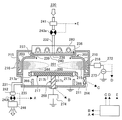
図1には、本発明の実施形態に係る基板処理装置100が示されている。
基板処理装置100は、被処理基板として用いられるウエハ200を処理する装置であり、先述のようにMMT装置であって、処理容器203を備えた処理炉202を有し、処理炉202の内側の空間が処理室201として用いられている。処理室201では、例えば金属元素含有膜とシリコン含有膜とが露出したウエハ200の処理がなされる。ウエハ200の表面に露出している金属元素含有膜は、例えば、タングステン、タンタル、窒化チタン、窒化タングステン、ルテニウム等の少なくとも何れかを含有している。また、ウエハ200の表面に露出している露出しているシリコン含有膜は、例えば、Poly−Si膜や、アモルファスシリコン膜、シリコン膜、シリコン酸化膜等の少なくとも何れかを含有している。
FIG. 1 shows a substrate processing apparatus 100 according to an embodiment of the present invention.
The substrate processing apparatus 100 is an apparatus for processing a
処理容器203は、第1の容器として用いられている例えばドーム形状の上側容器210と、第2の容器として用いられている例えば碗型の下側容器211とで、上側容器210が下側容器211の上に被せられるようにして形成されている。上側容器210は酸化アルミニウム又は石英等の非金属材料で形成されており、下側容器211はアルミニウムで形成されている。尚、上側容器210を非金属材料で形成し、下側容器211をアルミニウムで形成することと併せて、後述するサセプタ217を窒化アルミニウムや、セラミックス、又は石英等の非金属材料で構成することによって、処理の際に被処理基板の膜中に取り込まれる金属汚染が低減する。
The
また、基板処理装置100は、シャワーヘッド236を有する。
シャワーヘッド236は、処理室201の上部に設けられていて、キャップ状の蓋体233と、ガス導入口234と、バッファ室237と、開口238と、遮蔽プレート240と、ガス吹出口239とを備えている。バッファ室237は、ガス導入口234より導入されたガスを分散するための分散空間として用いられている。ガス導入口234には、ガスを供給するガス供給管232が接続されており、ガス供給管232は、開閉弁であるバルブ243aと、流量制御器として用いられ、流量制御手段として用いられているマスフローコントローラ241とを介して反応ガス230を収納するガスボンベ(不図示)に繋がっている。シャワーヘッド236は、反応ガス230を処理室201に供給するために用いられている。
In addition, the substrate processing apparatus 100 includes a
The
また、基板処理装置100においては、後述するサセプタ217の周囲から処理室201の底方向へ基板処理後のガスが流れるように、下側容器211の側壁にガスを排気するガス排気口235が形成されていて、ガス排気口235にはガスを排気するガス排気管231が接続されている。ガス排気管231は、圧力調整器として用いられているAPC242と、開閉弁として用いられているバルブ243bとを介して排気装置として用いられている真空ポンプ246に接続されている。
Further, in the substrate processing apparatus 100, a
また、基板処理装置100は、供給される反応ガス230を励起させる放電機構として用いられていて、放電手段として用いられている筒状電極215を有する。筒状電極215は、処理容器203の外周に設置されていて、処理室201内におけるプラズマ生成領域224を囲むように配置されている。筒状電極215には、インピーダンスの整合を行う整合器272を介して高周波電力を印加する高周波電源273が接続されている。
The substrate processing apparatus 100 includes a
また、基板処理装置100は、筒状磁石216を有する。筒状磁石216は、筒状に形成されていて、磁界形成機構として用いられているとともに、磁界形成手段として用いられていて、例えば永久磁石で形成からなる。また、筒状磁石216は、筒状電極215の外表面の上下端近傍にそれぞれ1つが配置されている。上下の筒状磁石216、216は、処理室201の半径方向に沿った両端(内周端と外周端)にそれぞれ磁極を持ち、上下の筒状磁石216、216の磁極の向きが逆向きに設定されている。このため、内周部の磁極同士が互いに異極となっており、これにより、筒状電極215の内周面に沿って円筒軸方向に磁力線を形成するようになっている。
In addition, the substrate processing apparatus 100 has a
処理炉202は、ウエハ200をマグネトロン型プラズマ源でのマグネトロン放電により処理するために用いられており、先述の処理室201、処理容器203、サセプタ217、筒状電極215、筒状磁石216、シャワーヘッド236、及び排気口235等から構成されていて、処理室201でウエハ200をプラズマ処理することが可能となっている。
The
また、基板処理装置100は、遮蔽板223を有する。遮蔽板223は、筒状電極215及び筒状磁石216の周囲に配置されていて、筒状電極215及び筒状磁石216で形成される電界や磁界を外部環境や他処理炉等の装置に悪影響を及ぼさないように、電界や磁界を遮蔽する。
In addition, the substrate processing apparatus 100 includes a shielding plate 223. The shielding plate 223 is disposed around the
また、基板処理装置100は、処理室201に設けられ、ウエハ200を支持する第一基板支持部として用いられているサセプタ217を有する。サセプタ217は、ウエハ200を加熱する加熱部としても用いられている。また、サセプタ217の内部には、インピーダンスを変化させるための電極である電極217cが装備されていて、この電極がインピーダンス可変機構274を介して接地されている。インピーダンス可変機構274は、コイルや可変コンデンサから構成され、コイルのパターン数や可変コンデンサの容量値を制御することによって、サセプタ217等を介してウエハ200の電位を制御できるようになっている。
The substrate processing apparatus 100 also includes a
サセプタ217は、処理室201の底側中央に配置されている。サセプタ217は、例えば窒化アルミニウムやセラミックス、又は石英等の非金属材料で形成され、内部にヒータ217bが一体的に埋め込まれていて、ウエハ200を加熱することができるようになっている。より具体的には、サセプタ217はウエハ200を例えば700℃程度にまで加熱することができるように構成されている。このように、サセプタ217は、ウエハ200を加熱する加熱機構として用いられていて、加熱手段として用いられている。また、サセプタ217には貫通孔217aが形成されている。
The
また、サセプタ217をウエハ200の加熱機構として用い、加熱手段として用いること併せて、例えば加熱ランプ280等を処理室201に設ける等して、処理室201にウエハ200を加熱する加熱手段を設けても良い。即ち、基板処理装置100においては、第一基板支持部として用いられているサセプタ217、及び処理室201の少なくともいずれか一方にウエハ200を加熱する加熱部を設ければ良い。
In addition, using the
サセプタ217に加熱部を設けた場合、ウエハ200を後述するリフタピン266で支持して加熱する際に、サセプタ217とウエハ200との間でガスを加熱し、この加熱したガスをウエハ200に表面に供給することができるので、ウエハ200を均一に加熱することができる。また、温度が上昇し活性度が上昇したガスがウエハ200に下向きの面に供給されるため、ウエハ200の下向きの面への処理が良好になされる。
When the heating unit is provided in the
処理室201に加熱部を設けた場合は、処理室201内に存在する例えば還元性ガスと酸化性ガス等のガスを加熱することができ、ガスの活性度を向上させることができる。また、サセプタ217と処理室201との両方に加熱部を設けた場合は、ウエハ200の上向きの面と下向きの面とを同時に加熱することができ、ウエハ200の上向きの面と下向きの面との温度差を低減することができる。
When the heating unit is provided in the
また、基板処理装置100は、サセプタ昇降機構268を有する。サセプタ昇降機構268は、サセプタ217を昇降させるサセプタ昇降機構として用いられている。
Further, the substrate processing apparatus 100 includes a
また、基板処理装置100は、例えば3個のリフタピン266を有する。リフタピン266は、処理室201に設けられていて、ウエハ200をサセプタ217の上で支持する第二基板支持部として用いられている。リフタピン266は、サセプタ昇降機構268によりサセプタ217が下降した際に、サセプタ217と非接触な状態で貫通孔217aを突き抜けるような位置関係となるよう配置されている。
The substrate processing apparatus 100 includes, for example, three lifter pins 266. The lifter pins 266 are provided in the
また、基板処理装置100は、ゲートバルブ244を有する。ゲートバルブ244は、下側容器211の側壁に取り付けられていて、仕切弁として用いられている。ゲートバルブ244が開いている時には、搬送機構(不図示)により処理室201内にウエハ200を搬入することができ、処理室201内からウエハ200を搬出することができるようになる。また、ゲートバルブ244は、処理室201を気密に閉じることができる。
Further, the substrate processing apparatus 100 has a
また、基板処理装置100は、コントローラ121を有する。コントローラ121は、信号線Aを通じてAPC242、バルブ243b、真空ポンプ246を制御し、信号線Bを通じてサセプタ昇降機構268を制御し、信号線Cを通じてゲートバルブ244を制御し、信号線Dを通じて整合器272、高周波電源273を、信号線Eを通じてマスフローコントローラ241、バルブ243aを制御し、さらに図示しない信号線を通じてサセプタに埋め込まれたヒータやインピーダンス可変機構274等を制御する。
In addition, the substrate processing apparatus 100 includes a controller 121. The controller 121 controls the
以上のように構成された基板処理装置100においては、先述のように、サセプタ217が、処理室201に設けられ、ウエハ200を支持する第一基板支持部として用いられていて、リフタピン266が、処理室201に設けられていて、ウエハ200をサセプタ217の上で支持する第二基板支持部として用いられている。また、基板処理装置100においては、マスフローコントローラ241、バルブ243a、バルブ243b、シャワーヘッド236等がガス供給部として用いられていて、このガス供給部が、後述するように処理室201に酸化性ガス、窒素含有ガス、還元性ガス等のガスを供給する。ここで、酸化性ガスとは、酸素(O2)、亜酸化窒素(NO)、二酸化窒素(NO2)オゾン(O3)、過酸化水素(H2O2)、水(H2O)、等の少なくとも何れかを含有するガスである。窒素含有ガスとは、窒素(N2)、アンモニア(NH3)等の少なくとも何れかを含有するガスである。還元性ガスとは、水素(H2)、アンモニア(NH3)、一酸化炭素(CO)等の少なくとも何れかを含むガスである。酸素含有ガスは、好ましくは常温常圧状態で気体状の酸素含有ガスである。還元性ガスは、好ましくは水素含有ガスである。
In the substrate processing apparatus 100 configured as described above, as described above, the
また、基板処理装置100においては、先述のように、サセプタ217がウエハ200を加熱する加熱部として用いられていて、筒状電極215、筒状磁石216、高周波電源273等が処理室201内のガスを励起する励起部として用いられている。また、基板処理装置100においては、ガス排気管231、真空ポンプ246等が処理室201内を排気する排気部として用いられている。また、コントローラ121は、少なくとも、サセプタ昇降機構268と、マスフローコントローラ241等からなるガス供給部と、例えばサセプタ217からなる加熱部と、高周波電源273等を有する励起部と、真空ポンプ246等を有する排気部とを制御する制御部として用いられている。
Further, in the substrate processing apparatus 100, as described above, the
以上のように構成された基板処理装置100においては、半導体装置の製造工程の一工程として、ウエハ200の表面に対し、又はウエハ200の表面に形成された下地膜の表面に対して所定のプラズマ処理を施すことができる。このプラズマ処理は、コントローラ121が基板処理装置100の各部を制御することによりなされ、より具体的には、以下のようになされる。
In the substrate processing apparatus 100 configured as described above, a predetermined plasma is applied to the surface of the
即ち、処理室201の外部からウエハ200を搬送する搬送機構(不図示)によってウエハ200が処理室201内に搬入され、サセプタ217上に搬送される。この際、サセプタ217にウエハが搬送される搬送位置まで下降し、リフタピン266の先端がサセプタ217の貫通孔217aを通過し、これにより、サセプタ217表面よりも所定の高さ分だけリフタピン266が突き出た状態となる。次に、下側容器211に設けられたゲートバルブ244が開かれ、搬送機構(不図示)によってウエハ200がリフタピン266の先端に載置される。そして、搬送機構が処理室201外へ退避した後、ゲートバルブ244が閉じられる。そして、サセプタ217がサセプタ昇降機構268により上昇し、これにより、サセプタ217上面にウエハ200が載置された状態となり、サセプタ217は、さらにウエハ200を処理する位置まで上昇する。
That is, the
この際、サセプタ217に埋め込まれたヒータは予め加熱されており、搬入されたウエハ200を、室温から例えば700℃の範囲内における予め定められた所定の温度になるように加熱する。処理室201内の圧力は、真空ポンプ246、及びAPC242を用いて、例えば0.1〜1000Paの範囲内の予め定められた圧力に維持される。
At this time, the heater embedded in the
ウエハ200の温度が予め定められた処理温度に達し、安定化した後、ガス導入口234から遮蔽プレート240に形成されたガス吹出口239を介して、例えば酸素ガス、窒素ガス、希ガス等の処理ガスが処理室201に配置されているウエハ200のプラズマ処理がなされる処理面である上向きの面に向けて導入される。この際、導入され処理ガスの流量は、1〜10000sccmの範囲内における予め定められた流量とされる。処理ガスの導入と例えば同時に、整合器272を介して高周波電源273から筒状電極215に、例えば10〜3000Wの範囲内の予め定められた電力の高周波電力が印加される。高周波電力が印加される回路のインピーダンスは、インピーダンス可変機構274によって所望のインピーダンス値となるように制御されている。
After the temperature of the
筒状電極215に電圧が印加されると、筒状磁石216、216の磁界の影響を受けてマグネトロン放電が発生し、ウエハ200の上方空間に電荷をトラップしてプラズマ生成領域224に高密度プラズマが生成される。そして、生成された高密度プラズマにより、サセプタ217上のウエハ200の表面にプラズマ処理が施される。プラズマ処理が終わったウエハ200は、搬送機構(不図示)を用いて、基板搬入と逆の手順で処理室201外へ搬送される。
When a voltage is applied to the
図2には、基板処理装置100を用いた本発明の実施形態に係る半導体装置の製造方法の工程が示されている。図2に示されるように、最初の工程であるステップS100は搬入工程であり、コントローラ121は、搬送機構(不図示)を制御してウエハ200を処理室201内に搬入させる。
FIG. 2 shows steps of a method for manufacturing a semiconductor device according to an embodiment of the present invention using the substrate processing apparatus 100. As shown in FIG. 2, step S100, which is the first process, is a loading process, and the controller 121 controls the transfer mechanism (not shown) to load the
次の工程であるステップS200は加熱工程であり、コントローラ121は、基板処理装置100の各部を制御してウエハ200を加熱させる。この加熱工程は、ウエハ200がリフタピン266に載置された状態となるように搬送機構(不図示)等を制御するステップと、処理室201内を排気するように真空ポンプ246等を制御するステップと、処理室201内に還元性ガスを供給するようにバルブ243a等を制御するステップと、サセプタ217等にウエハ200を加熱させるステップとを有する。還元性のガスとしては、例えば水素ガスが用いられる。処理室201内への還元性ガスの供給と、ウエハ200の加熱とは、工程の一部又は全部が同時になされる。
Step S200, which is the next process, is a heating process, and the controller 121 controls each part of the substrate processing apparatus 100 to heat the
この加熱工程においては、還元性ガスを供給させつつ、ウエハ200が加熱させる。このため、ウエハ200が酸化しにくく、ウエハ200に形成された金属元素含有膜の意図しない酸化が抑制される。また、この加熱工程においては、リフタピン266に支持された状態でウエハ200が加熱される。このため、ヒータを有するサセプタ217に支持された状態でウエハ200が加熱される場合と比較して、ウエハ200は上側の面と下側の面とが均一に加熱される。また、リフタピン266で支持されているため、ウエハ200の下側の面の下方に空間が形成され、この空間にも還元性ガスが供給される。このように、ウエハ200裏面に還元性ガスを供給することにより、ウエハ200の下側の面に付着した酸素を除去することができる。よって、ウエハ200裏面から放出される微量な酸素による、ウエハ200の表面に形成された金属元素含有膜への意図しない酸化を防止することができる。
In this heating step, the
また、サセプタ217に設けられたヒータの他に、処理室に別途加熱手段としての加熱ランプ(不図示)を設けることにより、ウエハ200の上側の面と下側の面をより均一に加熱することができる。処理室201内の空間に熱エネルギを放射することにより、処理室201内に存在する還元性ガスを直接加熱できる。また、処理室201内の部材や内壁の表面を加熱することができ、処理室201内の部材や内壁表面に付着した酸素元素と還元性ガスとの反応効率を向上させることができ、酸素元素の除去効率を向上させることができる。
In addition to the heater provided in the
次の工程であるステップS300は処理工程であり、コントローラ121は、基板処理装置100の各部を制御してウエハ200に処理を施させる。この処理工程は、ウエハ200がサセプタ217に載置された状態となるようにサセプタ昇降機構268等を制御するステップと、ウエハ200を加熱するようにサセプタ217等を制御するステップと、処理室201内に酸化性ガスと還元性ガスとを供給するようにバルブ243a等を制御するステップと、処理室201内に供給された酸化性ガスと還元性ガスが励起するように高周波電源273等を制御するステップとを有する。ここで、酸化性ガスは、酸素含有ガスであり、還元性ガスは、水素含有ガスである。すなわち、ステップS300において、処理室201内に酸素ガスと水素ガスとを供給しても良い。
Step S300, which is the next step, is a processing step, and the controller 121 controls each part of the substrate processing apparatus 100 to perform processing on the
次のステップであるステップS400は、停止工程であり、コントローラ121は、ガスの供給を停止させる。この停止工程は、酸化性ガス供給を停止させるステップと、酸化性ガスの供給を停止させた後に、還元性ガスの供給を停止させるステップとを有する。酸化性ガスは、非励起状態であってもウエハ200を酸化させる可能性がある。このため、この停止工程では、先に酸素の供給を停止させ、処理室201内の酸化性ガス濃度を下げることによって、ウエハ200が不要に酸化することを抑制している。また、励起状態の水素が励起状態の酸素や非励起状態の酸素ガスよりも後まで処理室201内に残るので、処理中に、ウエハ200の金属元素含有膜が酸化されていたとしても、この酸化された金属元素含有膜が還元される。
Step S400, which is the next step, is a stop process, and the controller 121 stops the gas supply. This stopping process includes a step of stopping the supply of the oxidizing gas and a step of stopping the supply of the reducing gas after stopping the supply of the oxidizing gas. The oxidizing gas may oxidize the
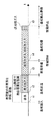
図3には、図2で工程を示した半導体装置の製造方法のシーケンスが示されている。
図3に示すように、ウエハ200が処理室201に搬入された後、時間t1から処理室201内の排気が開始され、時間t2までの間は処理室201内が排気される。そして、時間t2に処理室201内への、例えば水素ガス等の還元性ガスの供給が開始され、時間t2から時間t3までの間は処理室201内に還元性ガスを供給される。排気と還元性ガスの供給とがなされる時間t1から時間t3までの間に、処理室201内の雰囲気が還元され、置換される。排気することにより、処理室201内に混入した酸素元素を含むガスを排出することができ、また、真空度を高めた状態で還元性のガスを供給することにより、還元性のガスを加熱されたサセプタ217や処理室201内に存在する加熱された部材に効率良く当てることができ、活性度の高い還元性ガスを多く形成することができる。よって、処理室201内に存在する酸化性ガスや基板に付着した酸素元素の除去効率を向上させることができる。
FIG. 3 shows a sequence of a method for manufacturing a semiconductor device whose steps are shown in FIG.
As shown in FIG. 3, after the
時間t3から筒状電極215による放電の準備が開始され、時間t4に筒状電極215の放電が開始され、時間t5に筒状電極215の放電が停止される。時間t4から時間t5までの間は、処理室201内に還元性ガスと、酸化性ガスが供給される。時間t5からは、ウエハ200を排出するための準備がなされる。
Preparation for discharge by the
尚、上述のシーケンスにおいて、時間t1から時間t2になされた処理室201内の排気と、時間t2から時間t3になされた処理室201内への還元性ガスの供給のいずれか一方を省略して処理を簡便化しても良い。
In the above-described sequence, either the exhaust in the
図4には、図3に示すシーケンスの変形例が示されている。
図3に示すシーケンスでは、時間t2から時間t3までの間に処理室201内に還元性ガスを供給する際に処理室201内の圧力を調整していなかった。これに対して、この図4に示すシーケンスでは、時間t2から時間t3の間に処理室201内に還元性ガスを供給する際に、処理室201内の圧力を調整し、これにより還元性ガスからウエハ200への熱伝導量を制御し、ウエハ200の加熱量を制御している。処理室201内の圧力は、例えば、ウエハ200をサセプタ217上に移載するときの圧力よりも高い圧力にする。圧力を高くすることにより、ウエハ200の上側の面への加熱効率を向上させることができる。
FIG. 4 shows a modification of the sequence shown in FIG.
In the sequence shown in FIG. 3, the pressure in the
図4に示すシーケンスにおいて、ウエハ200は時間t1に処理室201内に搬送されると同時に処理室201の熱の影響を受け始める。この際、ウエハ200の温度変化は、ヒータを有するサセプタ217に対向する部分が最も大きいと考えられる。また、ウエハ200を加熱する際に、ウエハ200の昇温速度が速すぎるとウエハ200に過剰な熱応力が発生してしまう虞がある。一方、ウエハ200の昇温速度を遅くすると、処理時間が長くなってしまうという問題がある。図4に示すシーケンスでは、リフタピン266でウエハ200を支持し、ウエハ200とサセプタ217とを離間させた状態とし、処理室201内に還元性ガスを供給する際に処理室201内の圧力を調整することで、還元性ガスからウエハ200への熱伝導量を制御し、ウエハ200の昇温速度を制御している。
In the sequence shown in FIG. 4, the
また、このシーケンスでは、加熱工程S200での還元性ガスとして水素を用いている。ここで、水素は他のガスと比較して熱伝導率が高いので、還元ガスがウエハ200への熱伝導に寄与する割合が他の還元ガスを用いた場合よりも大きい。このため、処理室201内の圧力を調整することで、ウエハ200への熱伝導量を調整することは、水素ガス以外の還元ガスを用いる場合と比較してより有用である。
In this sequence, hydrogen is used as the reducing gas in the heating step S200. Here, since hydrogen has a higher thermal conductivity than other gases, the ratio of the reducing gas contributing to the heat conduction to the
尚、基板昇温行程での還元性ガスの一例として水素ガスを用いる例について説明をしたものの、水素ガス以外の還元性ガスを用いる場合であっても良い。すなわち、分子量が小さいガスであれば、処理室201内の圧力を調整することでウエハ200へ熱伝導量を好適に制御することができる。
In addition, although the example which uses hydrogen gas as an example of the reducing gas in a board | substrate temperature rising process was demonstrated, the case where reducing gases other than hydrogen gas are used may be sufficient. That is, if the gas has a small molecular weight, the amount of heat conduction to the
図5には、図3に示すシーケンスの第2の変形例が示されている。
図5に示すシーケンスでは、時間t2から時間t3までの間に処理室201内に還元性ガスを供給する際に処理室201内の圧力を調整することに加えて、時間t5に筒状電極215の放電を停止させることに先立ち、酸化性ガスの供給を停止させ、予め定められた所定の時間、処理室201内に還元性ガスだけを供給させた後、時間t5に還元性ガスの供給を停止させるとともに、筒状電極215の放電を停止させている。
FIG. 5 shows a second modification of the sequence shown in FIG.
In the sequence shown in FIG. 5, in addition to adjusting the pressure in the
処理室201内に還元性ガスだけを供給させる時間は、処理室201の体積、処理室201からの排気速度、処理室201内に還元性ガスが供給される速度等を考慮して定められ、例えば、1〜30秒程度に定められる。また、還元性ガスが処理室201内に供給される流量を、徐々に低減させていき時間t5で停止させるようにしても良いし、筒状電極215からの放電を徐々に低下させていき、時間t5に放電を停止させるようにしても良い。
The time for supplying only the reducing gas into the
また、発明者は、鋭意研究した結果、ウエハ200上に、金属元素含有膜とシリコン含有膜が積層された微細な凸構造が複数形成されている場合は、ウエハ200表面積が多くなり、金属元素含有膜が酸化される部位が生じる可能性があることを見出した。また、微細な凸構造が複数形成されている場合には、熱ストレスが加わり易くなる可能性が有ることを見出した。このようなウエハ200を用いる場合に、上述のように、還元性ガスを供給しつつ、ウエハ200をリフタピン266に支持した状態で加熱することにより、ウエハ200の熱ストレスによる反りを低減させつつ、ウエハ200上に形成された金属元素含有膜の酸化を防止することができる。
Further, as a result of intensive research, the inventors have found that when a plurality of fine convex structures in which a metal element-containing film and a silicon-containing film are laminated are formed on the
また、上述のシーケンスに加えて、励起状態の水素と励起状態の酸素でウエハ200を処理した後に酸化性ガスの供給を止めた状態で、ウエハ200をリフタピン266で上に保持した状態で、励起状態の水素や還元性ガスをウエハ200の下側に供給するようにしても良い。処理後にウエハ200の下側に活性な水素を供給することにより、ウエハ200の下側の面やサセプタ217の表面に付着した酸素元素を除去することができ、搬出工程でウエハ200の下側の面やサセプタ217の表面から脱離する酸素によるウエハ200上側の面に形成された膜の酸化を防止することができる。また、サセプタ217の表面やウエハ200の上側の面や下側の面、処理室201の内壁、処理室201内に設けられた部材の表面等を水素で終端処理することにより、これらの表面に酸素が付着したとしても、容易に酸素を除去することが可能となる。
Further, in addition to the above-described sequence, the
本発明は、特許請求の範囲に記載した通りであり、さらに次に付記した事項を含む。 The present invention is as described in the claims, and further includes the following items.
〔付記1〕
金属元素含有膜及びシリコン含有膜が露出した被処理基板を処理する処理室と、
前記処理室に設けられ、被処理基板を支持する第一基板支持部と、
前記処理室に設けられ、被処理基板を前記第一基板支持部の上で支持する第二基板支持部と、
前記処理室にガスを供給するガス供給部と、
被処理基板を加熱する加熱部と、
前記処理室内のガスを励起する励起部と、
前記処理室内を排気する排気部と、
少なくとも前記ガス供給部、前記励起部、及び前記排気部を制御する制御部と、
を有し、
前記制御部は、
被処理基板が前記第二基板支持部に支持されている状態で、前記ガス供給部に前記処理室内へ還元性ガスを供給させるとともに、前記加熱部に被処理基板を加熱させ、
被処理基板が、前記第一基板支持部に支持されている状態で、前記ガス供給部に前記処理室内へ酸化性ガス及び還元性ガスを供給させるとともに、供給された酸化性ガス及び還元性ガスを前記励起部に励起させるように制御する
基板処理装置。
[Appendix 1]
A processing chamber for processing the substrate to be processed in which the metal element-containing film and the silicon-containing film are exposed;
A first substrate support provided in the processing chamber and supporting a substrate to be processed;
A second substrate support provided in the processing chamber and supporting the substrate to be processed on the first substrate support;
A gas supply unit for supplying gas to the processing chamber;
A heating unit for heating the substrate to be processed;
An excitation unit for exciting the gas in the processing chamber;
An exhaust section for exhausting the processing chamber;
A control unit that controls at least the gas supply unit, the excitation unit, and the exhaust unit;
Have
The controller is
In a state where the substrate to be processed is supported by the second substrate support unit, the gas supply unit supplies the reducing gas into the processing chamber, and the heating unit heats the substrate to be processed.
In a state where the substrate to be processed is supported by the first substrate support part, the gas supply part is supplied with oxidizing gas and reducing gas into the processing chamber, and the supplied oxidizing gas and reducing gas are supplied. A substrate processing apparatus that controls the excitation unit to be excited.
〔付記2〕
前記加熱部は、前記第一基板支持部及び前記処理室の少なくともいずれか一方に設けられている付記1記載の基板処理装置。
[Appendix 2]
The substrate processing apparatus according to appendix 1, wherein the heating unit is provided in at least one of the first substrate support unit and the processing chamber.
〔付記3〕
金属元素含有膜及びシリコン含有膜が露出した被処理基板を処理室に搬入する搬入工程と、
被処理基板を加熱する加熱工程と、
被処理基板を処理する処理工程と、
を有し、
前記処理工程は、
被処理基板を第一基板支持部に載置するステップと、
加熱部が被処理基板を加熱するステップと、
ガス供給部が前記処理室内に酸化性ガス及び還元性ガスを供給するステップと、
供給された酸化性ガス及び還元性ガスを励起部が励起するステップと、
排気部が前記処理室を排気するステップと、
を有し、
前記加熱工程は、
被処理基板を、前記第一基板支持部の上で支持する第二基板支持部に載置するステップと、
前記排気部が前記処理室内を排気するステップと、
前記ガス供給部が前記処理室内に還元性ガスを供給するステップと、
前記加熱部が被処理基板を加熱するステップと、
を有する
半導体装置の製造方法。
[Appendix 3]
A carrying-in process of carrying the substrate to be processed, in which the metal element-containing film and the silicon-containing film are exposed, into the processing chamber;
A heating step for heating the substrate to be processed;
A processing step of processing a substrate to be processed;
Have
The processing step includes
Placing the substrate to be processed on the first substrate support;
A heating unit heating the substrate to be processed;
A gas supply unit supplying an oxidizing gas and a reducing gas into the processing chamber;
An excitation unit exciting the supplied oxidizing gas and reducing gas;
An exhaust section exhausting the processing chamber;
Have
The heating step includes
Placing the substrate to be processed on the second substrate support unit that supports the first substrate support unit;
The exhaust section exhausting the processing chamber;
The gas supply unit supplying a reducing gas into the processing chamber;
The heating unit heating the substrate to be processed;
A method for manufacturing a semiconductor device comprising:
〔付記4〕
ガスの供給を停止するガス停止工程をさらに有し、
前記停止工程は、
酸化性ガスの供給を停止するステップと、
酸化性ガスの供給を停止した後に、還元性ガスの供給を停止するステップと、
を有する
付記3記載の半導体装置の製造方法。
[Appendix 4]
A gas stop process for stopping the gas supply;
The stopping step includes
Stopping the supply of oxidizing gas;
Stopping the supply of reducing gas after stopping the supply of oxidizing gas;
The method for manufacturing a semiconductor device according to appendix 3, wherein:
〔付記5〕
金属膜及びシリコン膜が表面に露出している被処理基板を処理室に搬入する搬入工程と、
前記処理室内の雰囲気を還元性ガスで置換する置換工程と、
前記処理室内の雰囲気が還元性ガスで置換された後に、前記処理室に還元性ガスと酸化性ガスとを導入し、プラズマ放電することで被処理基板を処理する処理工程と、
を有し、
前記置換工程において、前記処理室内の圧力を調整することで還元性ガスから被処理基板への熱伝導量を制御する基板処理方法。
[Appendix 5]
A carrying-in process of carrying the substrate to be processed, in which the metal film and the silicon film are exposed on the surface, into the processing chamber;
A replacement step of replacing the atmosphere in the processing chamber with a reducing gas;
After the atmosphere in the processing chamber is replaced with a reducing gas, a processing step of processing the substrate to be processed by introducing a reducing gas and an oxidizing gas into the processing chamber and performing plasma discharge;
Have
A substrate processing method for controlling a heat conduction amount from a reducing gas to a substrate to be processed by adjusting a pressure in the processing chamber in the replacing step.
〔付記6〕
前記置換工程に先立ち、前記処理室内の雰囲気ガスを排気する排気行程をさらに有する服5記載の基板処理方法。
[Appendix 6]
The substrate processing method according to claim 5, further comprising an exhaust process of exhausting atmospheric gas in the processing chamber prior to the replacement step.
〔付記7〕
前記処理工程の後に、ガスの供給及びプラズマ放電を停止させるプラズマ停止工程をさらに有し、
前記停止工程においては、酸化性ガスの導入を停止させた後に、還元性ガスの導入とプラズマ放電とが停止させる付記5又は6記載の基板処理方法。
[Appendix 7]
After the processing step, further comprising a plasma stop step of stopping gas supply and plasma discharge,
The substrate processing method according to appendix 5 or 6, wherein, in the stopping step, introduction of the reducing gas and plasma discharge are stopped after the introduction of the oxidizing gas is stopped.
〔付記8〕
還元性ガスとして水素ガスを用いる付記5乃至7いずれか記載の基板処理方法。
[Appendix 8]
The substrate processing method according to any one of appendices 5 to 7, wherein hydrogen gas is used as the reducing gas.
〔付記9〕
前記置換工程では、処理室内の圧力を前記搬送工程の圧力よりも高くする基板処理方法。
[Appendix 9]
In the replacing step, the substrate processing method wherein the pressure in the processing chamber is higher than the pressure in the transfer step.
〔付記10〕
また、前記被処理基板上には、金属元素含有膜とシリコン含有膜が積層された微細な凸構造が複数形成されている。
[Appendix 10]
A plurality of fine convex structures in which a metal element-containing film and a silicon-containing film are laminated are formed on the substrate to be processed.
〔付記11〕
また、前記ガス停止工程と前記プラズマ停止工程の何れか若しくは両方の工程では、前記被処理基板を前記第二基板支持部で支持する。
[Appendix 11]
In one or both of the gas stop process and the plasma stop process, the substrate to be processed is supported by the second substrate support portion.
以上で説明をしたように、本発明は、基板処理装置と、半導体装置の製造方法とに適用することができる。 As described above, the present invention can be applied to a substrate processing apparatus and a method for manufacturing a semiconductor device.
100:基板処理装置
121:コントローラ
200:ウエハ
201:処理室
215:筒状電極
216:筒状磁石
217:サセプタ
231:ガス排気管
232:ガス供給管
236:シャワーヘッド
246:真空ポンプ
266:リフタピン
268:サセプタ昇降機構
273:高周波電源
100: substrate processing apparatus 121: controller 200: wafer 201: processing chamber 215: cylindrical electrode 216: cylindrical magnet 217: susceptor 231: gas exhaust pipe 232: gas supply pipe 236: shower head 246: vacuum pump 266: lifter pin 268 : Susceptor lifting mechanism 273: High frequency power supply
Claims (9)
前記処理室に設けられ、前記被処理基板を支持する第一基板支持部と、
前記処理室に設けられ、前記被処理基板を、前記第一基板支持部に形成された貫通孔から突き出た状態で支持する第二基板支持部と、
前記処理室にガスを供給するガス供給部と、
前記処理基板を加熱する加熱部と、
前記処理室内のガスを励起する励起部と、
前記処理室内を排気する排気部と、
少なくとも前記ガス供給部、前記励起部、及び前記排気部を制御する制御部と、
を有し、
前記制御部は、
前記被処理基板が前記第一基板支持部に形成された貫通孔から突き出た状態で前記第二基板支持部に支持され、前記ガス供給部に前記被処理基板の裏面へ還元性ガスを供給させるとともに、前記加熱部に前記被処理基板を加熱させ、
前記被処理基板が前記第一基板支持部に支持されている状態で、前記ガス供給部に前記処理室内へ酸化性ガス及び還元性ガスを供給させるとともに、供給された前記酸化性ガス及び前記還元性ガスを前記励起部に励起させるように制御する
基板処理装置。 A processing chamber for processing the substrate to be processed in which the metal element-containing film and the silicon-containing film are exposed;
Provided in the processing chamber, a first substrate support portion for supporting the substrate to be processed,
Provided in the processing chamber, and the substrate to be processed, the second substrate supporting portion for supporting a state exiting thrust from the first substrate supporting portion which is formed in the through hole,
A gas supply unit for supplying gas to the processing chamber;
A heating unit for heating the processing substrate;
An excitation unit for exciting the gas in the processing chamber;
An exhaust section for exhausting the processing chamber;
A control unit that controls at least the gas supply unit, the excitation unit, and the exhaust unit;
Have
The controller is
The supported by the second substrate supporting portion in a state in which the substrate to be processed has left thrust from the through hole formed in the first substrate supporting unit, supplying a reducing gas to the back surface of the target substrate to the gas supply unit And let the heating unit heat the substrate to be processed,
In a state where the substrate to be processed is supported by the first substrate support part, the gas supply part supplies the oxidizing gas and the reducing gas to the processing chamber, and the supplied oxidizing gas and the reduced gas are supplied. A substrate processing apparatus for controlling the excitation gas to excite the excitation unit.
前記ガス供給部に前記被処理基板の裏面へ前記還元性ガスを供給させる際に、前記処理室内の圧力を制御する請求項1記載の基板処理装置。 The controller is
The substrate processing apparatus according to claim 1, wherein when the reducing gas is supplied to the back surface of the substrate to be processed, the pressure in the processing chamber is controlled.
前記ガス供給部に前記酸化性ガスを停止させた後に、前記還元ガスを停止させるとともに、前記励起部に励起を停止させるように制御する請求項1記載の基板処理装置。 The controller is
The substrate processing apparatus according to claim 1, wherein after the oxidizing gas is stopped in the gas supply unit, the reducing gas is stopped and the excitation unit is controlled to stop excitation.
前記被処理基板を加熱する加熱工程と、
前記加熱工程の後に前記被処理基板を処理する処理工程と、
を有し、
前記加熱工程は、
前記被処理基板を、第一基板支持部に形成された貫通孔から突き出た状態で第二基板支持部に支持するステップと、
前記処理室内を排気するステップと、
前記被処理基板を、前記第一基板支持部に形成された貫通孔から突き出た状態で前記第二基板支持部に支持し、前記被処理基板の裏面に還元性ガスを供給するステップと、
前記第一基板支持部から離して前記第二基板支持部で支持した前記被処理基板を加熱するステップと、
を有し、
前記処理工程は、
前記被処理基板を前記第一基板支持部に支持するステップと、
加熱部が前記被処理基板を加熱するステップと、
前記処理室内に酸化性ガス及び還元性ガスを供給するステップと、
供給された前記酸化性ガス及び前記還元性ガスを励起するステップと、
前記処理室を排気するステップと、
を有する
半導体装置の製造方法。 A carrying-in process of carrying the substrate to be processed, in which the metal element-containing film and the silicon-containing film are exposed, into the processing chamber;
A heating step of heating the substrate to be processed;
A processing step of processing the substrate to be processed after the heating step;
Have
The heating step includes
A step of supporting the substrate to be processed, the second substrate supporting portion in a state exiting thrust from the through hole formed in the first substrate supporting unit,
Exhausting the processing chamber;
The substrate to be processed, is supported on said second substrate supporting portion in a state exiting thrust from the first substrate supporting portion which is formed in the through hole and supplying a reducing gas to the back surface of the substrate to be processed,
Heating the substrate to be processed supported by the second substrate support unit apart from the first substrate support unit;
Have
The processing step includes
Supporting the substrate to be processed on the first substrate support;
A heating unit heating the substrate to be processed;
Supplying an oxidizing gas and a reducing gas into the processing chamber;
Exciting the supplied oxidizing gas and reducing gas;
Evacuating the processing chamber;
A method for manufacturing a semiconductor device comprising:
前記処理室内の圧力を調整することで前記還元性ガスから前記被処理基板への熱伝導量を制御する請求項5記載の半導体装置の製造方法。 In the step of supplying the reducing gas into the processing chamber in the heating step,
The method according to claim 5, wherein controlling the amount of heat conduction to the substrate to be processed from the reducing gas by adjusting the pressure in the processing chamber.
前記ガスの供給を停止する工程は、
前記酸化性ガスの供給を停止するステップと、
前記酸化性ガスの供給を停止した後に、前記還元性ガスの供給を停止するステップと、
を有する
請求項5又は6記載の半導体装置の製造方法。 The treatment step further includes a step of stopping the supply of gas,
The step of stopping the supply of the gas,
Stopping the supply of the oxidizing gas;
Stopping the supply of the reducing gas after stopping the supply of the oxidizing gas;
A method for manufacturing a semiconductor device according to claim 5 or 6.
前記酸化性ガスの供給を停止した後に、前記還元性ガスの供給を停止するとともに前記励起を停止するステップを有する
請求項7記載の半導体装置の製造方法。 The step of stopping the supply of the gas ,
The method of manufacturing a semiconductor device according to claim 7, further comprising: stopping the supply of the reducing gas and stopping the excitation after stopping the supply of the oxidizing gas.
Priority Applications (3)
| Application Number | Priority Date | Filing Date | Title |
|---|---|---|---|
| JP2012032682A JP6066571B2 (en) | 2012-02-17 | 2012-02-17 | Substrate processing apparatus and semiconductor device manufacturing method |
| KR1020130016322A KR101435866B1 (en) | 2012-02-17 | 2013-02-15 | Substrate processing apparatus and method of manufacturing semiconductor device |
| US13/769,505 US9147573B2 (en) | 2012-02-17 | 2013-02-18 | Substrate processing apparatus and method of manufacturing semiconductor device |
Applications Claiming Priority (1)
| Application Number | Priority Date | Filing Date | Title |
|---|---|---|---|
| JP2012032682A JP6066571B2 (en) | 2012-02-17 | 2012-02-17 | Substrate processing apparatus and semiconductor device manufacturing method |
Publications (3)
| Publication Number | Publication Date |
|---|---|
| JP2013171843A JP2013171843A (en) | 2013-09-02 |
| JP2013171843A5 JP2013171843A5 (en) | 2015-03-19 |
| JP6066571B2 true JP6066571B2 (en) | 2017-01-25 |
Family
ID=49218673
Family Applications (1)
| Application Number | Title | Priority Date | Filing Date |
|---|---|---|---|
| JP2012032682A Active JP6066571B2 (en) | 2012-02-17 | 2012-02-17 | Substrate processing apparatus and semiconductor device manufacturing method |
Country Status (3)
| Country | Link |
|---|---|
| US (1) | US9147573B2 (en) |
| JP (1) | JP6066571B2 (en) |
| KR (1) | KR101435866B1 (en) |
Families Citing this family (1)
| Publication number | Priority date | Publication date | Assignee | Title |
|---|---|---|---|---|
| US20180076026A1 (en) | 2016-09-14 | 2018-03-15 | Applied Materials, Inc. | Steam oxidation initiation for high aspect ratio conformal radical oxidation |
Family Cites Families (12)
| Publication number | Priority date | Publication date | Assignee | Title |
|---|---|---|---|---|
| JP2002008999A (en) * | 2000-06-23 | 2002-01-11 | Mitsubishi Electric Corp | Manufacturing method for semiconductor device |
| JP4669605B2 (en) * | 2000-11-20 | 2011-04-13 | 東京エレクトロン株式会社 | Cleaning method for semiconductor manufacturing equipment |
| US6559039B2 (en) * | 2001-05-15 | 2003-05-06 | Applied Materials, Inc. | Doped silicon deposition process in resistively heated single wafer chamber |
| JP2004128019A (en) * | 2002-09-30 | 2004-04-22 | Applied Materials Inc | Method and apparatus for plasma processing |
| US8066894B2 (en) * | 2005-03-16 | 2011-11-29 | Hitachi Kokusai Electric Inc. | Substrate processing method and substrate processing apparatus |
| JP4829013B2 (en) | 2006-06-14 | 2011-11-30 | 株式会社日立国際電気 | Semiconductor device manufacturing method and substrate processing apparatus |
| JP4961179B2 (en) * | 2006-08-08 | 2012-06-27 | 株式会社日立国際電気 | Substrate processing apparatus and semiconductor device manufacturing method |
| JP2008091667A (en) * | 2006-10-03 | 2008-04-17 | Hitachi Kokusai Electric Inc | Method of treating substrate |
| US8083963B2 (en) * | 2007-02-08 | 2011-12-27 | Applied Materials, Inc. | Removal of process residues on the backside of a substrate |
| JP5564311B2 (en) * | 2009-05-19 | 2014-07-30 | 株式会社日立国際電気 | Semiconductor device manufacturing method, substrate processing apparatus, and substrate manufacturing method |
| JP5396180B2 (en) * | 2009-07-27 | 2014-01-22 | 東京エレクトロン株式会社 | Selective oxidation treatment method, selective oxidation treatment apparatus, and computer-readable storage medium |
| JP5548163B2 (en) * | 2010-09-14 | 2014-07-16 | 株式会社日立国際電気 | Substrate transport mechanism, substrate processing apparatus, and semiconductor device manufacturing method |
-
2012
- 2012-02-17 JP JP2012032682A patent/JP6066571B2/en active Active
-
2013
- 2013-02-15 KR KR1020130016322A patent/KR101435866B1/en active IP Right Grant
- 2013-02-18 US US13/769,505 patent/US9147573B2/en active Active
Also Published As
| Publication number | Publication date |
|---|---|
| KR101435866B1 (en) | 2014-09-01 |
| US9147573B2 (en) | 2015-09-29 |
| US20140057456A1 (en) | 2014-02-27 |
| JP2013171843A (en) | 2013-09-02 |
| KR20130095226A (en) | 2013-08-27 |
Similar Documents
| Publication | Publication Date | Title |
|---|---|---|
| JP6000665B2 (en) | Semiconductor device manufacturing method, substrate processing apparatus, and program | |
| JP6240712B1 (en) | Semiconductor device manufacturing method, substrate processing apparatus, and program | |
| JP6446418B2 (en) | Semiconductor device manufacturing method, substrate processing apparatus, and program | |
| US20100227478A1 (en) | Substrate processing apparatus and method of manufacturing semiconductor | |
| KR20130032281A (en) | Substrate processing apparatus, method of manufacturing semiconductor device, and recording medium | |
| JP5220062B2 (en) | Semiconductor device manufacturing apparatus and semiconductor device manufacturing method | |
| JP2012054399A (en) | Semiconductor manufacturing apparatus and method for manufacturing semiconductor | |
| JP6479713B2 (en) | Semiconductor device manufacturing method, program, and substrate processing apparatus | |
| JP6022785B2 (en) | Semiconductor device manufacturing method, substrate processing apparatus, and program | |
| JP6066571B2 (en) | Substrate processing apparatus and semiconductor device manufacturing method | |
| JP2006278619A (en) | Semiconductor-manufacturing apparatus | |
| JP2012114267A (en) | Manufacturing method of semiconductor device, and substrate processing apparatus | |
| JP5793028B2 (en) | Substrate processing apparatus and semiconductor device manufacturing method | |
| JP5171584B2 (en) | Substrate mounting table for substrate processing apparatus, substrate processing apparatus, and method for manufacturing semiconductor device | |
| JPWO2007077718A1 (en) | Substrate processing method and substrate processing apparatus | |
| JP5918574B2 (en) | Substrate processing apparatus and semiconductor device manufacturing method | |
| WO2005055298A1 (en) | Plasma processing apparatus and multi-chamber system | |
| JP2009224755A (en) | Method of manufacturing semiconductor device, and substrate processing apparatus | |
| JP2006005287A (en) | Substrate treatment method | |
| JP2013197449A (en) | Substrate processing method and substrate processing device | |
| JP2010097993A (en) | Plasma treatment method | |
| JP2009152233A (en) | Semiconductor fabrication equipment | |
| JP2011187637A (en) | Semiconductor manufacturing device | |
| JP2010118489A (en) | Method for manufacturing semiconductor device | |
| JP2007208169A (en) | Substrate processing method |
Legal Events
| Date | Code | Title | Description |
|---|---|---|---|
| A521 | Request for written amendment filed |
Free format text: JAPANESE INTERMEDIATE CODE: A523 Effective date: 20150130 |
|
| A621 | Written request for application examination |
Free format text: JAPANESE INTERMEDIATE CODE: A621 Effective date: 20150130 |
|
| A977 | Report on retrieval |
Free format text: JAPANESE INTERMEDIATE CODE: A971007 Effective date: 20150924 |
|
| A131 | Notification of reasons for refusal |
Free format text: JAPANESE INTERMEDIATE CODE: A131 Effective date: 20151006 |
|
| A521 | Request for written amendment filed |
Free format text: JAPANESE INTERMEDIATE CODE: A523 Effective date: 20151202 |
|
| A131 | Notification of reasons for refusal |
Free format text: JAPANESE INTERMEDIATE CODE: A131 Effective date: 20160517 |
|
| A521 | Request for written amendment filed |
Free format text: JAPANESE INTERMEDIATE CODE: A523 Effective date: 20160705 |
|
| TRDD | Decision of grant or rejection written | ||
| A01 | Written decision to grant a patent or to grant a registration (utility model) |
Free format text: JAPANESE INTERMEDIATE CODE: A01 Effective date: 20161128 |
|
| A61 | First payment of annual fees (during grant procedure) |
Free format text: JAPANESE INTERMEDIATE CODE: A61 Effective date: 20161220 |
|
| R150 | Certificate of patent or registration of utility model |
Ref document number: 6066571 Country of ref document: JP Free format text: JAPANESE INTERMEDIATE CODE: R150 |
|
| S111 | Request for change of ownership or part of ownership |
Free format text: JAPANESE INTERMEDIATE CODE: R313111 |
|
| R350 | Written notification of registration of transfer |
Free format text: JAPANESE INTERMEDIATE CODE: R350 |
|
| R250 | Receipt of annual fees |
Free format text: JAPANESE INTERMEDIATE CODE: R250 |
|
| R250 | Receipt of annual fees |
Free format text: JAPANESE INTERMEDIATE CODE: R250 |
|
| R250 | Receipt of annual fees |
Free format text: JAPANESE INTERMEDIATE CODE: R250 |
|
| R250 | Receipt of annual fees |
Free format text: JAPANESE INTERMEDIATE CODE: R250 |
|
| R250 | Receipt of annual fees |
Free format text: JAPANESE INTERMEDIATE CODE: R250 |