JP6060930B2 - Seedling transplanter - Google Patents

Seedling transplanter Download PDF

Info

Publication number
JP6060930B2
JP6060930B2 JP2014074241A JP2014074241A JP6060930B2 JP 6060930 B2 JP6060930 B2 JP 6060930B2 JP 2014074241 A JP2014074241 A JP 2014074241A JP 2014074241 A JP2014074241 A JP 2014074241A JP 6060930 B2 JP6060930 B2 JP 6060930B2
Authority
JP
Japan
Prior art keywords
planting
seedling
planting device
transmission
auxiliary
Prior art date
Legal status (The legal status is an assumption and is not a legal conclusion. Google has not performed a legal analysis and makes no representation as to the accuracy of the status listed.)
Expired - Fee Related
Application number
JP2014074241A
Other languages
Japanese (ja)
Other versions
JP2015195743A5 (en
JP2015195743A (en
Inventor
塩崎 孝秀
塩崎  孝秀
Current Assignee (The listed assignees may be inaccurate. Google has not performed a legal analysis and makes no representation or warranty as to the accuracy of the list.)
Iseki and Co Ltd
Original Assignee
Iseki and Co Ltd
Priority date (The priority date is an assumption and is not a legal conclusion. Google has not performed a legal analysis and makes no representation as to the accuracy of the date listed.)
Filing date
Publication date
Application filed by Iseki and Co Ltd filed Critical Iseki and Co Ltd
Priority to JP2014074241A priority Critical patent/JP6060930B2/en
Publication of JP2015195743A publication Critical patent/JP2015195743A/en
Publication of JP2015195743A5 publication Critical patent/JP2015195743A5/ja
Application granted granted Critical
Publication of JP6060930B2 publication Critical patent/JP6060930B2/en
Expired - Fee Related legal-status Critical Current
Anticipated expiration legal-status Critical

Links

Images

Landscapes

  • Transplanting Machines (AREA)

Description

本発明は、苗を圃場に植え付ける、植付装置を備える苗移植機に関する。   The present invention relates to a seedling transplanting machine including a planting device for planting seedlings in a field.

乗用型田植機など、圃場に苗を植え付ける苗移植機では、一般的に機体後方に配置された苗載せ台に積載されている苗マットから、苗を取り圃場に植え付ける植付装置が備えられている。植付装置としては、例えば、特許文献1及び2に記載されるように、左右方向の植付駆動軸を回転中心にして回転する左右のロータリケースの両端部に、苗取り爪と苗押出体を有した苗植付具を配置して、ロータリケースの回転中に苗植付具の先端部をロータリケースの回転外周へ突出させて、略楕円形状の植付軌跡線を描いて苗の分離、植付作動を行わせる技術が知られている。   In seedling transplanters that plant seedlings in the field, such as a riding rice transplanter, a planting device is generally provided that takes seedlings from a seedling mat that is loaded on a seedling stand placed at the rear of the aircraft and plantes them in the field. Yes. As a planting device, for example, as described in Patent Documents 1 and 2, seedling catching nails and a seedling extrudate are provided at both ends of a left and right rotary case that rotates about a planting drive shaft in the left-right direction. A seedling planting tool with a slab is placed, the tip of the seedling planting tool protrudes to the rotating outer periphery of the rotary case during rotation of the rotary case, and a seedling is separated by drawing a substantially elliptical planting trajectory line Techniques for performing planting operations are known.

また、上記構成の植付装置では、苗植付部を上昇させて植付クラッチが切れるときに、植付伝動軸の慣性回転により、所定の位置で停止することができるように構成されている。これにより、植付装置が土中に入り込んだまま停止し、付着した泥土が苗を取ることを妨げて苗が植え付けられない箇所が発生することを防止すると共に、苗植付再開時の苗と植付装置の距離が一定になり、次の苗の植付タイミングを安定させることができる。   Moreover, in the planting apparatus of the said structure, when raising a seedling planting part and a planting clutch is cut | disconnected, it is comprised so that it can stop in a predetermined position by the inertia rotation of a planting transmission shaft. . As a result, the planting device stops while entering the soil, prevents the adhering mud from taking seedlings and prevents the occurrence of places where seedlings cannot be planted. The distance of the planting device becomes constant, and the planting timing of the next seedling can be stabilized.

特開2007−89515号公報JP 2007-89515 A 特開2001−299029号公報JP 2001-299029 A

しかしながら、エンジンのアイドリング中や極低速時等で、植付伝動軸を回転させる出力が低いときには、植付クラッチが切れた後に植付伝動軸が殆ど回転しなくなるため、植付装置は、植付クラッチを切ったときの姿勢で停止する。このため、植付装置が土中に入り込んだ状態で停止すると、付着した泥が苗を掻き取ることを妨げ、苗の植え付けられない箇所が発生したり、走行を再開した際に泥土との接触抵抗で植付装置が破損したりする問題があった。   However, when the output to rotate the planting transmission shaft is low, such as when the engine is idling or at a very low speed, the planting transmission shaft almost stops rotating after the planting clutch is disconnected. Stop in the same posture as when the clutch was disengaged. For this reason, if the planting device stops in a state where it has entered the soil, the adhering mud will prevent the seedling from being scraped off, and there will be places where the seedling cannot be planted, or contact with the mud when traveling is resumed. There was a problem that the planting device was damaged by resistance.

本発明は、上記に鑑みてなされたものであって、植付装置の作動時における駆動力の伝達状態に関わらず、植付装置の停止時には、予め設定された位置で停止させることのできる苗移植機を提供することを目的とする。   The present invention has been made in view of the above, and a seedling that can be stopped at a preset position when the planting device is stopped regardless of the transmission state of the driving force during the operation of the planting device. The purpose is to provide a transplanter.

上述した課題を解決し、目的を達成するために、本発明の請求項1に記載の苗移植機は、走行車体(2)の後部に設ける苗を積載する苗載置部材(51)と、前記苗載置部材(51)から苗を取って植え付ける植付装置(60)と、前記植付装置(60)に駆動力を伝動する植付駆動機構(87)を設けた苗移植機において、記植付装置(60)の停止位置を検知する停止位置検知部材(94)を設け停止位置検知部材(94)が検知する前記植付装置(60)の停止位置が設定位置でなければ前記植付装置(60)を設定位置に移動させる補助駆動装置(85)を設け、前記植付駆動機構(87)に回転部材(88)を設け、前記補助駆動装置(85)は、前記停止位置検知部材(94)が検知する前記植付装置(60)の停止位置が設定位置でなければ作動して前記回転部材(88)を回転させ、前記植付装置(60)を設定位置に移動させる構成としたことを特徴とする苗移植機である。 In order to solve the above-described problems and achieve the object, the seedling transplanter according to claim 1 of the present invention includes a seedling placement member (51) for loading seedlings provided at the rear portion of the traveling vehicle body (2), the seedling mounting member and planted example attached planting device taking seedlings from (51) (60), said planting device (60) planting drive mechanism for transmitting the driving force to (87) is provided with seedling transplanter in front detects the stop position of KiUe with devices (60) provided with a stop position detecting member (94), the stop position is the set position of the planting device (60) to said stop position detecting member (94) detects if Kere such a the an auxiliary driving device for moving the planting device (60) to the set position (85), the rotating member (88) provided the in planting drive mechanism (87), the auxiliary drive (85) Is the stop position of the planting device (60) detected by the stop position detection member (94). If it is not a setting position, it will operate | move, the said rotation member (88) will be rotated, and the said planting apparatus (60) was set as the structure moved to a setting position, It is a seedling transplanter characterized by the above-mentioned.

また、請求項2に記載の発明は、前記走行車体(2)に駆動源(10)を設け、該駆動源(10)から伝達される駆動力を変速する変速装置(16)を設け、前記変速装置(16)を切り替えて前記走行車体(2)の前後進と走行出力を切り替える変速操作部材(35)を設け、前記変速操作部材(35)の操作位置を検知する位置検知部材(125)を設け、前記植付装置(60)への駆動力の伝動を入切する植付クラッチ機構(82)を設け、該位置検知部材(125)が変速操作部材(35)の後進側への操作を検知すると該植付クラッチ機構(82)を切状態とし、前記植付装置(60)への伝動を停止させる構成としたことを特徴とする請求項1に記載の苗移植機である。 According to a second aspect of the present invention, the traveling vehicle body (2) is provided with a drive source (10), a transmission (16) for shifting the driving force transmitted from the drive source (10) is provided, A position detection member (125) for detecting the operation position of the speed change operation member (35) is provided by switching the speed change device (16) to provide a speed change operation member (35) for switching the forward and backward travel and the travel output of the traveling vehicle body (2) And a planting clutch mechanism (82) for turning on and off the transmission of the driving force to the planting device (60) is provided, and the position detection member (125) is operated to the reverse side of the speed change operation member (35). The seedling transplanting machine according to claim 1 , wherein the planting clutch mechanism (82) is turned off when transmission is detected, and transmission to the planting device (60) is stopped .

また、請求項3に記載の発明は、前記変速操作部材(35)の後進側への操作を規制する操作規制部材(126)を設け、該操作規制部材(126)の規制状態と規制解除状態に切り替える規制入切部材(127)を設け、前記植付装置(60)を設定位置に移動したことを前記停止位置検知部材(94)が検知すると、前記操作規制部材(126)を規制解除位置に移動させると共に、前記位置検知部材(125)が後進から前進への前記変速操作部材(35)の移動を検知すると、前記操作規制部材(126)を規制位置に移動させることを特徴とする請求項2に記載の苗移植機である。 According to a third aspect of the present invention, there is provided an operation restricting member (126) for restricting the reverse operation of the speed change operating member (35), and the restricting state and the restriction releasing state of the operation restricting member (126). When the stop position detection member (94) detects that the planting device (60) has been moved to the set position, the operation restriction member (126) is moved to the restriction release position. When the position detection member (125) detects the movement of the speed change operation member (35) from reverse to forward, the operation restriction member (126) is moved to a restriction position. Item 3. A seedling transplanter according to Item 2 .

また、請求項4に記載の発明は、前記植付駆動機構(87)から駆動力を受けて作動し、前記苗載置部材(51)を左右方向に摺動させる摺動機構(100)と、前記苗載置部材(51)の左右端部への到達を検知する端部検知部材(105)と、前記補助駆動装置(85)を入切する補助駆動操作部材(130)を設け、前記補助駆動操作部材(130)を操作して前記補助駆動装置(85)を作動させると、前記摺動機構(100)と植付装置(60)が作動し、前記端部検知部材(105)が検知状態になると補助駆動装置(85)を停止させることを特徴とする請求項2または3のいずれか1項に記載の苗移植機である。 According to a fourth aspect of the present invention, there is provided a sliding mechanism (100) that operates by receiving a driving force from the planting driving mechanism (87) and slides the seedling placement member (51) in the left-right direction. An end detection member (105) for detecting arrival of the seedling placement member (51) to the left and right ends, and an auxiliary drive operation member (130) for turning on and off the auxiliary drive device (85), When the auxiliary drive operating member (130) is operated to operate the auxiliary drive device (85), the sliding mechanism (100) and the planting device (60) are operated, and the end detection member (105) is operated. The seedling transplanter according to any one of claims 2 and 3, wherein the auxiliary driving device (85) is stopped when the detection state is reached.

また、請求項5に記載の発明は、請求項4に記載の苗移植機において、前記植付装置(60)が通過する際の苗の姿勢を整える苗案内部材(110)を前記苗載置部材(51)の下部に設け、該苗案内部材(110)に植付装置(60)の通過を検知する通過検知部材(115)を設け、前記端部検知部材(105)が検知状態になると、前記通過検知部材(115)が検知状態となる位置に植付装置(60)が移動するまで前記補助駆動装置(85)を作動させることを特徴とする請求項4に記載の苗移植機である。 The invention described in claim 5 is the seedling transplanting machine according to claim 4, wherein the seedling placement member (110) for adjusting the posture of the seedling when the planting device (60) passes is placed on the seedling placement. When a passage detection member (115) for detecting passage of the planting device (60) is provided in the lower part of the member (51) and the seedling guide member (110) is detected, the end detection member (105) is in a detection state. The seedling transplanter according to claim 4, wherein the auxiliary driving device (85) is operated until the planting device (60) moves to a position where the passage detection member (115) is in a detection state. is there.

また、請求項6に記載の発明は、前記通過検知部材(115)は、前記植付装置(60)が苗を保持しているか否かを判定し、前記植付装置(60)が苗を保持しているときは、前記補助駆動装置(85)を停止させ、前記植付装置(60)が苗を保持していないときは、前記停止位置検知部材(94)が設定位置を検知すると前記補助駆動装置(85)を停止させることを特徴とする請求項に記載の苗移植機である。 In the invention according to claim 6, the passage detection member (115) determines whether or not the planting device (60) holds a seedling, and the planting device (60) determines the seedling. When holding, the auxiliary drive device (85) is stopped, and when the planting device (60) is not holding a seedling, the stop position detection member (94) detects the set position and 6. The seedling transplanter according to claim 5 , wherein the auxiliary drive device (85) is stopped .

(削除)(Delete)

(削除)(Delete)

(削除)(Delete)

請求項1に記載の苗移植機は、植付装置(60)が設定位置で停止していないときには、補助駆動装置(85)によって植付装置(60)を設定位置まで移動させることにより、植付装置(60)が土中に入り込んだ状態で停止することを防止できるので、植付装置(60)に付着した泥土が、苗載置部材(51)から苗を取ることを妨げる状態になることを防止でき、苗を確実に圃場に植え付けることができる。
また、植付装置(60)の停止時に自動的に設定位置まで植付装置(60)が移動することにより、植付装置(60)への伝動を遮断すると、駆動力が伝動される状態となっても植付装置(60)が回転することが無く、植付装置(60)に付着した泥土が周囲に飛び散ることが防止される。
また、補助駆動装置(85)で回転部材(88)を回転させて植付駆動機構(87)を介して植付装置(60)に駆動力を伝動することにより、余分な操作が不要となり、操作性が向上すると共に、植付装置(60)に泥土が付着することを防止できる。
また、植付装置(60)が停止し、停止位置が設定位置でないときに補助駆動装置(85)を差動させることにより、苗の植付作業時に補助駆動装置(85)が植付駆動機構(87)の駆動力伝達の抵抗となることを防止できるので、走行や苗の植付動作が安定し、作業能率が向上する
Seedling transplantation machine according to claim 1, when the planting device (60) is not stopped in the set position, by moving the planting device (60) to a set position by the auxiliary drive (85), planting Since it can prevent that an attaching apparatus (60) stops in the state which entered the soil, the mud which adhered to the planting apparatus (60) will be in the state which prevents taking a seedling from the seedling mounting member (51). This can be prevented and seedlings can be reliably planted in the field.
In addition, when the planting device (60) is automatically moved to the set position when the planting device (60) is stopped, when the transmission to the planting device (60) is cut off, the driving force is transmitted. Even if it becomes, a planting apparatus (60) does not rotate and it is prevented that the mud adhering to the planting apparatus (60) scatters around.
Further, by rotating the rotating member (88) with the auxiliary driving device (85) and transmitting the driving force to the planting device (60) via the planting driving mechanism (87), an extra operation becomes unnecessary. While operativity improves, it can prevent that mud adheres to a planting apparatus (60).
Further, when the planting device (60) is stopped and the stop position is not the set position, the auxiliary drive device (85) is differentiated, so that the auxiliary drive device (85) is planted by the planting drive mechanism when planting seedlings. Since it becomes possible to prevent the driving force transmission resistance of (87) from occurring, traveling and seedling planting operations are stabilized, and work efficiency is improved .

請求項2に記載の苗移植機は、請求項1の発明の効果に加えて、走行車体(2)が後進操作されると、植付クラッチ機構(82)を切状態にすると共に、補助駆動装置(85)が植付装置(60)を設定位置に移動させる構成としたことにより、植付装置(60)が土中に入り込まない姿勢で後進走行することができるので、植付装置(60)に泥土が付着し、苗載置部材(51)から苗を取り損ない、苗が植え付けられない箇所が発生することを防止できるIn addition to the effect of the invention of claim 1, the seedling transplanting machine according to claim 2 sets the planting clutch mechanism (82) in a disconnected state and an auxiliary drive when the traveling vehicle body (2) is operated backward. Since the device (85) is configured to move the planting device (60) to the set position, the planting device (60) can travel backward in a posture that does not enter the soil, so that the planting device (60 ) Can be prevented from adhering to the mud, failing to remove the seedling from the seedling placement member (51), and generating a place where the seedling cannot be planted .

請求項3に記載の苗移植機は、請求項2の発明の効果に加えて、植付装置(60)が設定位置に移動するまでは、操作規制部材(126)が変速操作部材(35)の後進操作を規制することにより、植付装置(60)が設定位置に移動する前に後進走行が開始されることを防止できる。これにより、植付装置(60)に泥土が付着することや、接触抵抗により植付装置(60)が破損することを防止できる
また、変速操作部材(35)が前進側に操作されると操作規制部材(126)が自動的に規制位置に移動することにより、次の後進操作時に植付装置(60)が設定位置に移動するまで変速操作部材(35)が後進側に操作できなくなるので、植付装置(60)に泥土が付着することや、接触抵抗により植付装置(60)が破損することを防止できる
In addition to the effect of the invention of claim 2, in the seedling transplanting machine according to claim 3, until the planting device (60) moves to the set position, the operation regulating member (126) is the speed change operation member (35). By restricting the reverse operation, it is possible to prevent reverse travel from being started before the planting device (60) moves to the set position. Thereby, it can prevent that mud adheres to a planting apparatus (60), or that a planting apparatus (60) is damaged by contact resistance .
Further, when the speed change operation member (35) is operated to the forward side, the operation restricting member (126) automatically moves to the restricting position, so that the planting device (60) moves to the set position during the next reverse operation. The shifting operation member (35) cannot be operated in the reverse direction until it is done, so that it is possible to prevent mud from adhering to the planting device (60) and damage to the planting device (60) due to contact resistance .

請求項4に記載の苗移植機は、請求項2または3の発明の効果に加えて、補助駆動操作部材(130)を操作すると、変速装置(16)の操作位置、あるいは植付クラッチ機構(82)の入切状態にかかわらず、補助駆動装置(85)を入切することができるので、植付作業前の苗載置部材(51)の左右位置の調節や、メンテナンス時の植付装置(60)の作動を行うことができ、作業能率を向上させることができる
また、端部検知部材(105)が苗載置部材(51)の左右端部への到達を検知すると補助駆動装置(85)が停止することにより、苗載置部材(51)の端部の到達に合わせて補助駆動装置(85)を停止操作する必要がなくなるので、苗載置部材(51)の移動中に他の作業を行うことができ、作業能率を向上させることができる
In addition to the effect of the invention of claim 2 or 3 , the seedling transplanting machine according to claim 4 operates the auxiliary drive operating member (130), the operation position of the transmission (16), or the planting clutch mechanism ( 82) Since the auxiliary drive device (85) can be turned on and off regardless of the on / off state of 82), the adjustment of the left and right positions of the seedling placement member (51) before the planting operation, and the planting device during maintenance The operation of (60) can be performed, and the work efficiency can be improved .
Further, when the end detection member (105) detects the arrival of the seedling placement member (51) to the left and right ends, the auxiliary drive device (85) stops, so that the end of the seedling placement member (51) is stopped. Since it is not necessary to stop the auxiliary drive device (85) in accordance with the arrival, other work can be performed while the seedling placement member (51) is moving, and work efficiency can be improved .

請求項5に記載の苗移植機は、請求項4の発明の効果に加えて、苗載置部材(51)が端部まで移動すると、植付装置(60)を苗案内部材(110)を通過する位置まで移動させることにより、植付装置(60)の作動後すぐに苗を圃場に植え付け始めることができるので、作業能率が向上する
また、通過検知部材(115)で植付装置(60)を検知することにより、植付作業時の速度に関係なく補助駆動装置(85)を停止させることができるので、植付作業開始時の圃場までの距離が一定となる。これにより、作業能率を向上させることができると共に、苗の植付位置を揃い易くさせることができ、植付精度を向上させることができる
In addition to the effect of the invention of claim 4, the seedling transplanter according to claim 5 is configured such that when the seedling placement member (51) moves to the end, the planting device (60) moves the seedling guide member (110). By moving to the passing position, the seedling can be started to be planted in the field immediately after the planting device (60) is operated, so that the work efficiency is improved .
Further, by detecting the planting device (60) with the passage detection member (115), the auxiliary drive device (85) can be stopped regardless of the speed at the time of planting work. The distance to the field is constant. Thereby, while being able to improve work efficiency, it can make it easy to arrange the planting position of a seedling, and can improve planting accuracy .

請求項6に記載の苗移植機は、請求項の発明の効果に加えて、植付装置(60)が苗を保持しているときに苗案内部材(110)に到達すると補助駆動装置(85)が停止することにより、植付装置(60)の作動後すぐに苗を圃場に植え付け始めることができるので、作業効率を向上させることができる
また、植付装置(60)が苗を保持していないときは、停止位置検知部材(94)が設定位置を検知すると補助駆動装置(85)を停止させることにより、植付装置(60)が土中に入り込んだ状態で停止することを防止できるので、植付装置(60)に付着した泥土が、苗載置部材(51)から苗を取ることを妨げる状態になることを防止でき、苗を確実に圃場に植え付けることができる
In addition to the effect of the invention of claim 5 , the seedling transplanting machine according to claim 6 is configured such that when the planting device (60) reaches the seedling guide member (110) when holding the seedling, the auxiliary driving device ( By stopping 85), the seedling can be started to be planted in the field immediately after the planting device (60) is operated, so that the work efficiency can be improved .
Moreover, when the planting device (60) does not hold the seedling, the planting device (60) is stopped by stopping the auxiliary drive device (85) when the stop position detecting member (94) detects the set position. Since it can prevent stopping in the state which got in the soil, it can prevent that the mud adhering to the planting apparatus (60) will be in the state which prevents taking a seedling from the seedling mounting member (51). Can be reliably planted in the field .

(削除)(Delete)

(削除)(Delete)

(削除)(Delete)

図1は、実施形態に係る苗移植機の側面図である。FIG. 1 is a side view of a seedling transplanter according to an embodiment. 図2は、図1に示す苗移植機の平面図である。FIG. 2 is a plan view of the seedling transplanter shown in FIG. 図3は、図1に示すミッションケースの断面図である。3 is a cross-sectional view of the mission case shown in FIG. 図4は、植付装置が取り付けられる苗植付体の平面図である。FIG. 4 is a plan view of a seedling planting body to which the planting device is attached. 図5は、図1に示す植付装置の詳細図である。FIG. 5 is a detailed view of the planting apparatus shown in FIG. 図6は、図5のA−A矢視図である。FIG. 6 is an AA arrow view of FIG. 図7は、図1に示す苗載置台の下端付近の側面図である。FIG. 7 is a side view of the vicinity of the lower end of the seedling mounting table shown in FIG. 図8は、図7のB−B矢視図である。FIG. 8 is a view taken along the line BB in FIG. 図9は、図2に示す変速レバーのガイドをするレバーガイド溝の平面図である。FIG. 9 is a plan view of a lever guide groove for guiding the speed change lever shown in FIG. 図10は、図1に示す苗移植機の要部構成図である。FIG. 10 is a main part configuration diagram of the seedling transplanter shown in FIG. 図11は、補助伝動モータの駆動力で作動する植付装置が苗を保持している場合の説明図である。FIG. 11 is an explanatory diagram when the planting device that operates with the driving force of the auxiliary transmission motor holds the seedling. 図12は、補助伝動モータの駆動力で作動する植付装置が苗を保持していない場合の説明図である。FIG. 12 is an explanatory diagram when the planting device that operates with the driving force of the auxiliary transmission motor does not hold seedlings. 図13は、実施形態に係る苗移植機の変形例であり、後輪の側面図である。FIG. 13 is a modified example of the seedling transplanter according to the embodiment, and is a side view of a rear wheel.

以下に、本発明に係る苗移植機の実施形態を図面に基づいて詳細に説明する。なお、この実施形態によりこの発明が限定されるものではない。また、下記実施形態における構成要素には、当業者が置換可能、且つ、容易なもの、或いは実質的に同一のものが含まれる。   Hereinafter, an embodiment of a seedling transplanter according to the present invention will be described in detail with reference to the drawings. In addition, this invention is not limited by this embodiment. In addition, constituent elements in the following embodiments include those that can be easily replaced by those skilled in the art or those that are substantially the same.

〔実施形態〕
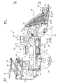
図1は、実施形態に係る苗移植機の側面図である。図2は、図1に示す苗移植機の平面図である。なお、以下の説明においては、前後、左右の方向基準は、苗移植機の操縦席からみて、車体の走行方向を基準として、前後、左右の基準を規定している。本実施形態に係る苗移植機1の走行車体2は、左右一対の前輪4と、同様に左右一対の後輪5とを有しており、走行時には各車輪が駆動する四輪駆動車としている。これにより、走行車体2は、圃場や道路を走行することが可能になっている。また、走行車体2の後部には、苗植付部昇降機構40によって昇降可能な苗植付部50が備えられている。
Embodiment
FIG. 1 is a side view of a seedling transplanter according to an embodiment. FIG. 2 is a plan view of the seedling transplanter shown in FIG. In the following description, the front / rear / left / right direction reference defines the front / rear, left / right reference with respect to the traveling direction of the vehicle body as viewed from the cockpit of the seedling transplanter. The traveling vehicle body 2 of the seedling transplanter 1 according to the present embodiment has a pair of left and right front wheels 4 and a pair of left and right rear wheels 5 as well, and is a four-wheel drive vehicle that drives each wheel during traveling. . Thereby, the traveling vehicle body 2 can travel on a farm field or a road. In addition, a seedling planting section 50 that can be moved up and down by a seedling planting section lifting mechanism 40 is provided at the rear of the traveling vehicle body 2.

この走行車体2は、車体の略中央に配置されたメインフレーム7と、このメインフレーム7の上に搭載されたエンジン10と、エンジン10の動力を駆動輪と苗植付部50とに伝える動力伝達装置15と、を備えている。つまり、本実施形態に係るこの苗移植機1では、動力源であるエンジン10で発生した動力は、走行車体2を前進や後進させるために用いるのみでなく、苗植付部50を駆動させるためにも使用され、ディーゼル機関やガソリン機関等の熱機関が用いられる。   The traveling vehicle body 2 includes a main frame 7 disposed substantially at the center of the vehicle body, an engine 10 mounted on the main frame 7, and power for transmitting the power of the engine 10 to the drive wheels and the seedling planting unit 50. And a transmission device 15. That is, in the seedling transplanter 1 according to the present embodiment, the power generated by the engine 10 that is a power source is used not only for moving the traveling vehicle body 2 forward and backward, but also for driving the seedling planting unit 50. And heat engines such as diesel engines and gasoline engines are used.

また、エンジン10は、走行車体2の左右方向における略中央で、且つ、作業者が乗車時に足を載せるフロアステップ26よりも上方に突出させた状態で配置されている。また、フロアステップ26は、走行車体2の前部とエンジン10の後部との間に渡って設けられてメインフレーム7上に取り付けられており、その一部が格子状になることにより、靴に付いた泥を圃場に落とせるようになっている。また、このフロアステップ26の後方には、後輪5のフェンダを兼ねたリアステップ27が設けられている。このリアステップ27は、後方に向うに従って上方に向う方向に傾斜した傾斜面を有しており、エンジン10の左右それぞれの側方に配置されている。   Further, the engine 10 is arranged at a substantially center in the left-right direction of the traveling vehicle body 2 and in a state of protruding upward from a floor step 26 on which an operator puts his / her foot when getting on. Further, the floor step 26 is provided between the front portion of the traveling vehicle body 2 and the rear portion of the engine 10 and is mounted on the main frame 7. The mud can be dropped on the field. A rear step 27 that also serves as a fender for the rear wheel 5 is provided behind the floor step 26. The rear step 27 has an inclined surface that is inclined upward as it goes rearward, and is disposed on each of the left and right sides of the engine 10.

エンジン10は、これらのフロアステップ26とリアステップ27とから上方に突出しており、これらのステップから突出している部分には、エンジン10を覆うエンジンカバー11が配設されている。即ち、エンジンカバー11は、フロアステップ26とリアステップ27とから上方に突出した状態で、エンジン10を覆っている。   The engine 10 protrudes upward from the floor step 26 and the rear step 27, and an engine cover 11 that covers the engine 10 is disposed in a portion protruding from these steps. That is, the engine cover 11 covers the engine 10 in a state of protruding upward from the floor step 26 and the rear step 27.

また、走行車体2には、エンジンカバー11の上部に操縦席28が設置されており、操縦席28の前方で、且つ、走行車体2の前側中央部には、操縦部30が配設されている。この操縦部30は、フロアステップ26の床面から上方に突出した状態で配置されており、フロアステップ26の前部側を左右に分断している。   Further, the traveling vehicle body 2 is provided with a cockpit 28 above the engine cover 11, and a steering unit 30 is disposed in front of the cockpit 28 and at the front center of the traveling vehicle body 2. Yes. The control unit 30 is arranged in a state of protruding upward from the floor surface of the floor step 26 and divides the front side of the floor step 26 into left and right.

操縦部30の前部には、開閉可能なフロントカバー31が設けられている。また、操縦部30の上部には、操作装置を作動させる操作レバー等や計器類、ハンドル32が配設されている。このハンドル32は、作業者が前輪4を操舵操作することにより走行車体2を操舵する操舵部材として設けられており、操縦部30内の操作装置等を介して前輪4を転舵させることが可能になっている。また、操作レバーとしては、走行車体2の前後進と走行出力を切替操作する変速操作部材である変速レバー35と、走行車体2の走行速度を、走行する場所に応じた速度に切り替える副走行操作部材である副変速レバー38とが、機体右側と左側に配設されている。   A front cover 31 that can be opened and closed is provided at the front of the control unit 30. In addition, an operation lever and the like for operating the operation device, instruments, and a handle 32 are disposed on the upper portion of the control unit 30. The handle 32 is provided as a steering member that steers the traveling vehicle body 2 by an operator steering the front wheel 4, and can steer the front wheel 4 via an operation device or the like in the control unit 30. It has become. In addition, as the operation lever, a shift lever 35 that is a shift operation member that switches between forward and backward travel of the traveling vehicle body 2 and a traveling output, and a sub traveling operation that switches the traveling speed of the traveling vehicle body 2 to a speed corresponding to the traveling place. Sub-transmission levers 38, which are members, are disposed on the right and left sides of the machine body.

また、フロアステップ26における操縦部30の左右それぞれの側方に位置する部分には、補給用の苗を載せておく予備苗載台65が配置されている。この予備苗載台65は、フロアステップ26の床面から突出した支持軸(鉛直軸)によって回転自在に支持されており、作業者の手、または電動モータ等の回動部材によって回動させることが可能になっている。   In addition, on the portions of the floor step 26 located on the left and right sides of the control unit 30, a spare seedling stage 65 on which a replenishment seedling is placed is arranged. The preliminary seedling stage 65 is rotatably supported by a support shaft (vertical shaft) protruding from the floor surface of the floor step 26, and is rotated by a worker's hand or a rotating member such as an electric motor. Is possible.

また、動力伝達装置15は、エンジン10から伝達される駆動力を変速する変速装置である油圧式無段変速機16と、この油圧式無段変速機16にエンジン10からの動力を伝えるベルト式動力伝達機構17と、を有している。このうち、油圧式無段変速機16とは、HST(HydroStaticTransmission)と云われる静油圧式の無段変速装置として構成されている。このため、油圧式無段変速機16は、エンジン10からの動力で駆動する油圧ポンプによって油圧を発生させ、この油圧を油圧モータで機械的な力(回転力)に変換して出力する。これにより、油圧式無段変速機16は、エンジン10で発生する動力を、走行車体2を走行させる力に変換する。   The power transmission device 15 includes a hydraulic continuously variable transmission 16 that is a transmission for shifting the driving force transmitted from the engine 10, and a belt type that transmits power from the engine 10 to the hydraulic continuously variable transmission 16. And a power transmission mechanism 17. Of these, the hydraulic continuously variable transmission 16 is configured as a hydrostatic continuously variable transmission called HST (HydroStatic Transmission). For this reason, the hydraulic continuously variable transmission 16 generates hydraulic pressure by a hydraulic pump that is driven by power from the engine 10, and converts this hydraulic pressure into mechanical force (rotational force) by a hydraulic motor and outputs it. Thereby, the hydraulic continuously variable transmission 16 converts the power generated by the engine 10 into a force that causes the traveling vehicle body 2 to travel.

その際に、油圧式無段変速機16は、回転力の方向や回転速度を変更することにより、走行車体2の前後進及び走行速度を変更することが可能になっており、変速レバー35は、この油圧式無段変速機16の出力及び出力方向を変更することによって、走行車体2の前後進及び走行速度を操作することが可能になっている。   At that time, the hydraulic continuously variable transmission 16 can change the forward and backward travel and the traveling speed of the traveling vehicle body 2 by changing the direction and the rotational speed of the rotational force. By changing the output and output direction of the hydraulic continuously variable transmission 16, it is possible to operate the forward and backward travel and the traveling speed of the traveling vehicle body 2.

この油圧式無段変速機16は、エンジン10よりも前方で、且つ、フロアステップ26の床面よりも下方に配置されており、本実施形態に係る苗移植機1では、走行車体2の上面から見て、エンジン10の前方に配置されている。   The hydraulic continuously variable transmission 16 is disposed in front of the engine 10 and below the floor surface of the floor step 26. In the seedling transplanter 1 according to the present embodiment, the upper surface of the traveling vehicle body 2 is disposed. As viewed from the front side of the engine 10.

また、ベルト式動力伝達機構17は、エンジン10の出力軸に取り付けたプーリと、油圧式無段変速機16の入力軸に取り付けたプーリと、双方のプーリに巻き掛けたベルトと、さらに、このベルトの張力を調整するテンションプーリと、を備えている。これにより、ベルト式動力伝達機構17は、エンジン10で発生した動力を、ベルトを介して油圧式無段変速機16に伝達可能になっている。   The belt-type power transmission mechanism 17 includes a pulley attached to the output shaft of the engine 10, a pulley attached to the input shaft of the hydraulic continuously variable transmission 16, a belt wound around both pulleys, A tension pulley for adjusting the tension of the belt. As a result, the belt-type power transmission mechanism 17 can transmit the power generated by the engine 10 to the hydraulic continuously variable transmission 16 via the belt.

さらに、動力伝達装置15は、ベルト式動力伝達機構17を介して油圧式無段変速機16に伝達され、油圧式無段変速機16で変速したエンジン10からの駆動力を各部に伝達する伝動装置であるミッションケース18を有している。このミッションケース18は、路上走行時や植付時等における走行車体2の作業速度を切り替える副変速機構(図示省略)を内設しており、メインフレーム7の前部に取り付けられている。副変速レバー38は、ミッションケース18内の副変速機構を操作することにより、走行車体2の走行速度を切り替えることが可能になっている。ミッションケース18は、ベルト式動力伝達機構17と油圧式無段変速機16とを介して伝達されたエンジン10からの出力を、当該ミッションケース18内の副変速機構で変速して、前輪4と後輪5への走行用動力と、苗植付部50への駆動用動力とに分けて出力可能になっている。   Further, the power transmission device 15 is transmitted to the hydraulic continuously variable transmission 16 via the belt-type power transmission mechanism 17 and transmits the driving force from the engine 10 shifted by the hydraulic continuously variable transmission 16 to each part. It has a mission case 18 as a device. The transmission case 18 has a sub-transmission mechanism (not shown) for switching the working speed of the traveling vehicle body 2 when traveling on the road or planting, and is attached to the front portion of the main frame 7. The auxiliary transmission lever 38 can switch the traveling speed of the traveling vehicle body 2 by operating the auxiliary transmission mechanism in the mission case 18. The transmission case 18 shifts the output from the engine 10 transmitted via the belt-type power transmission mechanism 17 and the hydraulic continuously variable transmission 16 by the auxiliary transmission mechanism in the transmission case 18, and The power can be output separately for the driving power to the rear wheel 5 and the driving power to the seedling planting section 50.

このうち、走行用動力は、一部が左右の前輪ファイナルケース21を介して前輪4に伝達可能になっており、残りが左右の後輪ギヤケース22を介して後輪5に伝達可能になっている。左右それぞれの前輪ファイナルケース21は、ミッションケース18の左右それぞれの側方に配設されており、左右の前輪4は、車軸を介して左右の前輪ファイナルケース21に連結されている。また、この前輪ファイナルケース21は、ハンドル32の操舵操作に応じて駆動し、前輪4を転舵させることが可能になっている。同様に、左右それぞれの後輪ギヤケース22には、車軸を介して後輪5が連結されている。一方、駆動用動力は、走行車体2の後部に設けた植付クラッチ(図示省略)に伝達され、この植付クラッチの係合時に植付伝動軸(図示省略)によって苗植付部50へ伝達される。   Among these, a part of the driving power can be transmitted to the front wheel 4 via the left and right front wheel final cases 21, and the rest can be transmitted to the rear wheel 5 via the left and right rear wheel gear cases 22. Yes. The left and right front wheel final cases 21 are disposed on the left and right sides of the mission case 18, respectively. The left and right front wheels 4 are connected to the left and right front wheel final cases 21 via axles. Further, the front wheel final case 21 is driven in accordance with the steering operation of the handle 32 and can steer the front wheel 4. Similarly, the rear wheels 5 are connected to the left and right rear wheel gear cases 22 via axles. On the other hand, the driving power is transmitted to a planting clutch (not shown) provided at the rear portion of the traveling vehicle body 2, and is transmitted to the seedling planting unit 50 by a planting transmission shaft (not shown) when the planting clutch is engaged. Is done.

また、走行車体2の後部に備えられる苗植付部50を昇降させる苗植付部昇降機構40は、昇降リンク装置41を有しており、苗植付部50は、この昇降リンク装置41を介して走行車体2に取り付けられている。この昇降リンク装置41は、走行車体2の後部と苗植付部50とを連結させる平行リンク機構42を備えている。この平行リンク機構42は、上リンクと下リンクとを有しており、これらのリンクが、メインフレーム7の後部端に立設した背面視門型のリンクベースフレーム43に回動自在に連結され、各リンクの他端側が苗植付部50に回転自在に連結されることにより、苗植付部50を昇降可能に走行車体2に連結している。   The seedling planting part lifting mechanism 40 for raising and lowering the seedling planting part 50 provided at the rear part of the traveling vehicle body 2 has a lifting link device 41, and the seedling planting unit 50 uses the lifting link device 41. It is attached to the traveling vehicle body 2 via. The lifting link device 41 includes a parallel link mechanism 42 that connects the rear portion of the traveling vehicle body 2 and the seedling planting portion 50. The parallel link mechanism 42 has an upper link and a lower link, and these links are rotatably connected to a rear-view portal-type link base frame 43 erected at the rear end of the main frame 7. The other end side of each link is rotatably connected to the seedling planting part 50, so that the seedling planting part 50 is connected to the traveling vehicle body 2 so as to be movable up and down.

また、苗植付部昇降機構40は、油圧によって伸縮する油圧昇降シリンダ44を有しており、油圧昇降シリンダ44の伸縮動作によって、苗植付部50を昇降させることが可能になっている。苗植付部昇降機構40は、その昇降動作によって、苗植付部50を非作業位置まで上昇させたり、対地作業位置(対地植付位置)まで下降させたりすることが可能になっている。   The seedling planting part lifting mechanism 40 has a hydraulic lifting cylinder 44 that expands and contracts by hydraulic pressure, and the seedling planting part 50 can be lifted and lowered by the expansion and contraction operation of the hydraulic lifting cylinder 44. The seedling planting part raising / lowering mechanism 40 can raise the seedling planting part 50 to the non-working position or lower it to the ground work position (ground planting position) by the raising / lowering operation.

また、苗植付部50は、苗を植え付ける範囲を複数の区画、或いは複数の列で植え付けることができ、本実施形態に係る苗移植機1では、苗を6つの区画で植え付ける、いわゆる6条植の苗植付部50になっている。この苗植付部50は、植付装置60と、苗載置台51及びフロート47を備えている。このうち、苗載置台51は、複数条の苗を積載する苗載置部材として設けられており、走行車体2の左右方向において仕切られた植付条数分の苗載せ面52を有し、それぞれの苗載せ面52に土付きのマット状苗を載置することが可能になっている。これにより、苗載置台51に載置した苗が植え付けられて無くなるたびに、圃場外に用意している苗を取りに戻る必要が無く、連続した作業を行えるので、作業能率が向上する。   In addition, the seedling planting unit 50 can plant a range in which a seedling is planted in a plurality of sections or a plurality of rows. In the seedling transplanting machine 1 according to the present embodiment, the seedling is planted in six sections. The seedling planting part 50 is provided. The seedling planting unit 50 includes a planting device 60, a seedling placement table 51, and a float 47. Among these, the seedling mounting table 51 is provided as a seedling mounting member for loading a plurality of seedlings, and has seedling mounting surfaces 52 for the number of planting strips partitioned in the left-right direction of the traveling vehicle body 2, It is possible to place a mat-like seedling with soil on each seedling placement surface 52. Thereby, it is not necessary to return the seedling prepared outside the field every time the seedling placed on the seedling placing stand 51 is planted, and continuous work can be performed, so that the work efficiency is improved.

また、植付装置60は、苗載置台51に載置された苗を苗載置台51から取って圃場に植え付ける装置になっている。この植付装置60は、2条毎に1つずつ配設されており、回転可能なロータリケース63に、2条分の植込杆61を回転可能に備えている。即ち、複数の植付装置60は、それぞれ植付条が割り当てられている。このうち、ロータリケース63は、植付装置60に駆動力を供給する植付伝動ケース64に対して回転可能に連結されており、植付伝動ケース64は、エンジン10から苗植付部50に伝達された動力を、植付装置60に供給する。つまり、植付伝動ケース64には、2つのロータリケース63が、機体左右方向の両側に連結されており、苗植付部50は、この植付伝動ケース64を3つ備えている。   Further, the planting device 60 is a device that takes the seedlings placed on the seedling placement stand 51 from the seedling placement stand 51 and places them in the field. This planting device 60 is disposed one by one for every two strips, and a rotary case 63 that can be rotated is rotatably provided with two studs 61. That is, the planting strip is assigned to each of the plurality of planting apparatuses 60. Among these, the rotary case 63 is rotatably connected to a planting transmission case 64 that supplies a driving force to the planting device 60, and the planting transmission case 64 is connected to the seedling planting unit 50 from the engine 10. The transmitted power is supplied to the planting device 60. That is, two rotary cases 63 are connected to the planting transmission case 64 on both sides in the left-right direction of the machine body, and the seedling planting unit 50 includes three planting transmission cases 64.

また、フロート47は、走行車体2の移動と共に、圃場面上を滑走して整地するものであり、走行車体2の左右方向における苗植付部50の中央に位置するセンターフロート48と、左右方向における苗植付部50の両側に位置するサイドフロート49と、を有している。   In addition, the float 47 slides on the farm scene along with the movement of the traveling vehicle body 2 to level the ground. The center float 48 located in the center of the seedling planting part 50 in the left-right direction of the traveling vehicle body 2 and the left-right direction Side floats 49 located on both sides of the seedling planting part 50 in FIG.

また、苗植付部50の下方側の位置における前側には、圃場の整地を行う整地用ロータ67が設けられている。この整地用ロータ67は、後輪ギヤケース22を介して伝達されるエンジン10からの出力によって回転可能に構成されている。   Further, a leveling rotor 67 for leveling the agricultural field is provided on the front side of the lower position of the seedling planting unit 50. The leveling rotor 67 is configured to be rotatable by the output from the engine 10 transmitted through the rear wheel gear case 22.

また、苗植付部50の左右両側には、次の植付条に進行方向の目安になる線を形成する線引きマーカ68が備えられている。即ち、線引きマーカ68は、苗移植機1が圃場内における直進前進時に、圃場の畦際で転回した後に直進前進する際の目印を圃場上に線引きする。この線引きマーカ68は、マーカモータ(図示省略)によって作動し、走行車体2が旋回するごとに、左右の線引きマーカ68が入れ替わって作動することができるように構成されている。この左右の線引きマーカ68の入れ替えは、マーカモータが接続されるコントローラ(図示省略)によって行う。即ち、コントローラは、走行車体2の旋回時に、左右の線引きマーカ68を交互に作動状態と非作動状態とに切り替えるマーカ切替装置としても設けられている。なお、左右の線引きマーカ68の線引き作用部は、図1及び図2に示す通り、円盤の外周部に複数の突起体を設け、回転自在にロッド部に装着したものとすると、圃場面との接地抵抗により確実に圃場面に線を形成することができ、次の植付作業位置での直進作業が行い易くなり、作業能率が向上する。   In addition, on both the left and right sides of the seedling planting part 50, there are provided drawing markers 68 for forming a line that is a guide in the traveling direction on the next planting line. That is, the line drawing marker 68 draws a mark on the field when the seedling transplanter 1 moves straight forward in the field and then moves straight forward on the field. The drawing marker 68 is operated by a marker motor (not shown), and is configured such that each time the traveling vehicle body 2 turns, the left and right drawing markers 68 can be switched to operate. The left and right drawing markers 68 are replaced by a controller (not shown) to which a marker motor is connected. That is, the controller is also provided as a marker switching device that alternately switches the left and right drawing markers 68 between the activated state and the inactivated state when the traveling vehicle body 2 turns. As shown in FIGS. 1 and 2, the drawing action portions of the left and right drawing markers 68 are provided with a plurality of protrusions on the outer periphery of the disk and are rotatably attached to the rod portion. The grounding resistance can surely form a line on the farm scene, making it easy to perform a straight-ahead operation at the next planting work position and improving work efficiency.

また、走行車体2における操縦席28の後方には、施肥装置70が搭載されている。この施肥装置70は、肥料を貯留する貯留ホッパ71と、貯留ホッパ71から供給される肥料を設定量ずつ繰り出す繰出し装置72と、繰出し装置72により繰り出される肥料を圃場に供給する施肥通路である施肥ホース74と、施肥ホース74に搬送風を供給することにより、施肥ホース74内の肥料を苗植付部50側に移送する起風装置であるブロア73と、を有している。さらに、施肥装置70は、苗植付部50の下方に配設されると共に、施肥ホース74によって肥料が移送される施肥ガイド75と、施肥ガイド75の前側に設けられると共に、施肥ホース74によって移送された肥料を、苗植付条の側部近傍に形成される施肥溝内に落とし込む作溝器76と、を有している。   Further, a fertilizer application device 70 is mounted behind the cockpit 28 in the traveling vehicle body 2. The fertilizer 70 is a storage hopper 71 that stores fertilizer, a feeding device 72 that feeds the fertilizer supplied from the storage hopper 71 by a set amount, and a fertilizer that is a fertilization passage that supplies the fertilizer fed by the feeding device 72 to the field. It has a hose 74 and a blower 73 that is a wind-up device for transferring the fertilizer in the fertilizer hose 74 to the seedling planting part 50 side by supplying the conveying wind to the fertilizer hose 74. Furthermore, the fertilizer application device 70 is disposed below the seedling planting unit 50, is provided with a fertilizer guide 75 to which fertilizer is transferred by the fertilizer hose 74, and is provided on the front side of the fertilizer guide 75, and is transferred by the fertilizer hose 74. And a groove producing device 76 for dropping the fertilizer into a fertilizer groove formed in the vicinity of the side of the seedling planting strip.

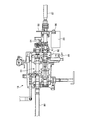
図3は、図1に示すミッションケースの断面図である。ミッションケース18は、内部に変速機構81を備えており、変速機構81には、油圧式無段変速機16から出力された駆動力のミッションケース18への伝動軸であるミッションケース入力軸80が接続されている。これにより、ミッションケース18には、油圧式無段変速機16で変速したエンジン10からの駆動力が伝達可能になっている。   3 is a cross-sectional view of the mission case shown in FIG. The transmission case 18 includes a transmission mechanism 81 therein, and the transmission mechanism 81 has a transmission case input shaft 80 that is a transmission shaft of the driving force output from the hydraulic continuously variable transmission 16 to the transmission case 18. It is connected. As a result, the driving force from the engine 10 shifted by the hydraulic continuously variable transmission 16 can be transmitted to the transmission case 18.

また、ミッションケース18には、ミッションケース18に伝達された駆動力を植付装置60側に伝動するか否かを切り替えることにより、ミッションケース18から植付装置60への伝動を切り替える植付クラッチ機構82が備えられている。この植付クラッチ機構82は、ミッションケース18に内設される変速機構81と、ミッションケース18から植付装置60側への出力軸であるミッションケース出力軸83との間での動力の伝達と遮断との切り替えが可能になっている。また、植付クラッチ機構82の近傍には、植付クラッチ機構82の入切を検知する入切検知部材である植付クラッチセンサ89が備えられている。   Further, in the mission case 18, a planting clutch that switches transmission from the mission case 18 to the planting device 60 by switching whether or not the driving force transmitted to the mission case 18 is transmitted to the planting device 60 side. A mechanism 82 is provided. This planting clutch mechanism 82 transmits power between a transmission mechanism 81 provided in the mission case 18 and a mission case output shaft 83 that is an output shaft from the mission case 18 to the planting device 60 side. Switching to blocking is possible. Further, in the vicinity of the planting clutch mechanism 82, a planting clutch sensor 89 that is an on / off detection member that detects on / off of the planting clutch mechanism 82 is provided.

このミッションケース出力軸83には、ミッションケース出力軸83によって出力される駆動力が伝達されることにより、エンジン10で発生した駆動力を植付装置60に伝動する植付駆動機構である植付ドライブシャフト87が接続されている。植付ドライブシャフト87は、ミッションケース出力軸83に対してメカロック防止クラッチ84を介して接続されている。このメカロック防止クラッチ84は、ミッションケース出力軸83から植付ドライブシャフト87への通常の駆動力の伝達時における回転方向では、係合することにより回転駆動力を伝達でき、反対方向の回転時にはスリップすることよりミッションケース出力軸83と植付ドライブシャフト87とが相対回転するようになっている。即ち、メカロック防止クラッチ84は、ワンウェイクラッチとして設けられている。   The mission case output shaft 83 is a planting drive mechanism that transmits the driving force generated by the engine 10 to the planting device 60 when the driving force output by the mission case output shaft 83 is transmitted. A drive shaft 87 is connected. The planting drive shaft 87 is connected to the mission case output shaft 83 via a mechanical lock preventing clutch 84. The mechanical lock preventing clutch 84 can transmit the rotational driving force by engaging in the rotational direction when transmitting the normal driving force from the mission case output shaft 83 to the planting drive shaft 87, and slips when rotating in the opposite direction. By doing so, the mission case output shaft 83 and the planting drive shaft 87 are relatively rotated. That is, the mechanical lock preventing clutch 84 is provided as a one-way clutch.

植付ドライブシャフト87には、回転部材である回転ギア88が装着されており、回転ギア88は、植付ドライブシャフト87と一体となって回転可能に装着されている。この回転ギア88には、補助駆動装置である補助伝動モータ85の出力軸に取り付けられるピニオンギア86と噛み合っている。これにより、植付ドライブシャフト87は、補助伝動モータ85の駆動時に補助伝動モータ85が発生する駆動力が、ピニオンギア86と回転ギア88とを介して伝達されることにより、回転駆動することが可能になっている。   A rotation gear 88, which is a rotating member, is mounted on the planting drive shaft 87, and the rotation gear 88 is rotatably mounted integrally with the planting drive shaft 87. The rotary gear 88 meshes with a pinion gear 86 attached to an output shaft of an auxiliary transmission motor 85 that is an auxiliary drive device. Thus, the planting drive shaft 87 can be driven to rotate by transmitting the driving force generated by the auxiliary transmission motor 85 through the pinion gear 86 and the rotating gear 88 when the auxiliary transmission motor 85 is driven. It is possible.

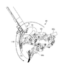
図4は、植付装置が取り付けられる苗植付体の平面図である。苗植付部50が有する複数の植付装置60は、植付伝動ケース64を支持すると共に、植付装置60に駆動力を伝動可能に構成される苗植付体90に備えられている。苗植付体90は、内部に伝動機構(図示省略)を有するメインケース91を有しており、メインケース91内の伝動機構には、植付ドライブシャフト87が連結されている。これにより、メインケース91内には、ミッションケース18から出力された駆動力が、植付ドライブシャフト87によって伝達可能になっている。また、メインケース91は、植付ドライブシャフト87から伝達された駆動力を出力する植付伝動軸92を支持しており、植付伝動軸92は、機体左右方向に延在している。   FIG. 4 is a plan view of a seedling planting body to which the planting device is attached. A plurality of planting devices 60 included in the seedling planting unit 50 are provided in a seedling planting body 90 configured to support the planting transmission case 64 and transmit the driving force to the planting device 60. The seedling planting body 90 has a main case 91 having a transmission mechanism (not shown) inside, and a planting drive shaft 87 is connected to the transmission mechanism in the main case 91. As a result, the driving force output from the mission case 18 can be transmitted to the main case 91 by the planting drive shaft 87. The main case 91 supports a planting transmission shaft 92 that outputs a driving force transmitted from the planting drive shaft 87, and the planting transmission shaft 92 extends in the left-right direction of the machine body.

複数の植付伝動ケース64は、メインケース91からの出力軸である植付伝動軸92にそれぞれ前端側が連結されている。各植付伝動ケース64は、内部にチェーン駆動機構(図示省略)を備えており、それぞれの植付伝動ケース64の後端側には、駆動力をロータリケース63に伝達する植付駆動軸93が、機体左右方向両側に突出している。植付伝動軸92から植付伝動ケース64に入力された駆動力は、内部のチェーン駆動機構によって植付駆動軸93に伝達され、植付駆動軸93によって出力される。植付駆動軸93には、ロータリケース63が連結されており、ロータリケース63及び植込杆61は、この植付駆動軸93から出力される駆動力により駆動する。   The plurality of planting transmission cases 64 are connected at their front ends to planting transmission shafts 92 that are output shafts from the main case 91. Each planting transmission case 64 includes a chain drive mechanism (not shown) inside, and a planting drive shaft 93 that transmits driving force to the rotary case 63 is provided on the rear end side of each planting transmission case 64. However, it protrudes on both sides of the aircraft. The driving force input from the planting transmission shaft 92 to the planting transmission case 64 is transmitted to the planting driving shaft 93 by the internal chain drive mechanism and output by the planting driving shaft 93. A rotary case 63 is connected to the planting drive shaft 93, and the rotary case 63 and the planting basket 61 are driven by a driving force output from the planting drive shaft 93.

また、メインケース91には、植付駆動軸93の回転角度を検出する回転センサ94が設けられている。この回転センサ94は、植付駆動軸93の回転角度を検出することにより、植付装置60の停止時に、植付装置60の停止位置を検知する停止位置検知部材として設けられている。   The main case 91 is provided with a rotation sensor 94 that detects the rotation angle of the planting drive shaft 93. The rotation sensor 94 is provided as a stop position detection member that detects the stop position of the planting device 60 when the planting device 60 is stopped by detecting the rotation angle of the planting drive shaft 93.

また、メインケース91には、植付ドライブシャフト87から駆動力を受けて作動し、苗載置台51を機体左右方向に往復摺動させる摺動機構であるリードカム機構100が備えられている。このリードカム機構100は、リードカム軸101と、摺動軸102とを備えている。リードカム軸101は、長手方向が左右方向と平行な状態で、左右方向の移動が規制され、且つ、軸心回りの回転が許容されて、メインケース91に支持されている。リードカム軸101は、植付ドライブシャフト87からエンジン10の駆動力が伝動されて、エンジン10からの駆動力により軸心回りに回転する。即ち、植付ドライブシャフト87は、リードカム軸101にエンジン10からの駆動力を伝動する。   In addition, the main case 91 is provided with a lead cam mechanism 100 that is a sliding mechanism that operates by receiving a driving force from the planting drive shaft 87 and reciprocates the seedling mounting table 51 in the left-right direction of the machine body. The lead cam mechanism 100 includes a lead cam shaft 101 and a sliding shaft 102. The lead cam shaft 101 is supported by the main case 91 with its longitudinal direction parallel to the left-right direction, restricted in movement in the left-right direction, and allowed to rotate about its axis. The drive force of the engine 10 is transmitted from the planted drive shaft 87 to the lead cam shaft 101, and the lead cam shaft 101 rotates around the axis by the drive force from the engine 10. That is, the planting drive shaft 87 transmits the driving force from the engine 10 to the lead cam shaft 101.

摺動軸102は、中央部がメインケース91に収容されて支持されている。摺動軸102は、リードカム軸101のカムに係合するリードカムを固着して、リードカム軸101に接触してリードカム軸101の回転により機体左右方向に往復移動する。摺動軸102は、両端が苗載置台51に連結されており、リードカム軸101の回転により左右方向に往復移動すると、苗載置台51を機体左右方向に往復摺動させる。これらのように、摺動軸102の機体左右方向の往復移動によって摺動軸102と共に往復移動する苗載置台51の移動範囲における端部付近には、苗載置台51の左右端部への到達を検知する端部検知部材である端寄せスイッチ105が、苗載置台51の左右両端側に配設されている。   The center of the slide shaft 102 is accommodated in and supported by the main case 91. The sliding shaft 102 is fixed to a lead cam that engages with the cam of the lead cam shaft 101, contacts the lead cam shaft 101, and reciprocates in the left-right direction of the machine body by the rotation of the lead cam shaft 101. Both ends of the sliding shaft 102 are connected to the seedling mounting table 51, and when the lead cam shaft 101 reciprocates in the left-right direction, the sliding shaft 102 reciprocates in the left-right direction of the machine body. As described above, in the vicinity of the end of the moving range of the seedling mounting table 51 that reciprocates with the sliding shaft 102 by the reciprocating movement of the sliding shaft 102 in the horizontal direction of the machine body, the left and right ends of the seedling mounting table 51 are reached. The edge-adjusting switch 105 that is an end detection member for detecting the seeds is disposed on both the left and right ends of the seedling placement table 51.

図5は、図1に示す植付装置の詳細図である。図6は、図5のA−A矢視図である。植付装置60のロータリケース63は、複数の植付用ギヤ(図示省略)からなる不等速伝動機構を内装しており、不等速伝動機構に対しては、植付伝動ケース64から供給された駆動力を、植付駆動軸93によって伝達可能になっている。また、植込杆61は、ロータリケース63に内装される不等速伝動機構の出力軸に連結されており、1つのロータリケース63に対して、植付駆動軸93を中心として点対称となる2箇所に配設されている。この植込杆61は、植付駆動軸93を中心とするロータリケース63の回転時に、ロータリケース63の回転速度に対して、不等速伝動機構により回転速度が不等速となって回転することが可能になっている。   FIG. 5 is a detailed view of the planting apparatus shown in FIG. FIG. 6 is an AA arrow view of FIG. The rotary case 63 of the planting device 60 includes an inconstant speed transmission mechanism composed of a plurality of planting gears (not shown). The inconstant speed transmission mechanism is supplied from the planting transmission case 64. The planted drive shaft 93 can transmit the generated driving force. In addition, the implantation rod 61 is connected to the output shaft of the inconstant speed transmission mechanism built in the rotary case 63, and is point-symmetric with respect to one rotary case 63 about the planting drive shaft 93. It is arranged at two places. When the rotary case 63 rotates around the planting drive shaft 93, the implantation rod 61 rotates at an irregular speed due to the inconstant speed transmission mechanism with respect to the rotational speed of the rotary case 63. It is possible.

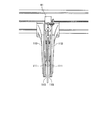
図7は、図1に示す苗載置台の下端付近の側面図である。図8は、図7のB−B矢視図である。苗載置台51の下部には、植付装置60が苗載置台51から苗を取った際に、苗の姿勢を整える苗案内部材である苗ガイド110が配設されている。この苗ガイド110は、1つのロータリケース63について1組が配設されており、1組の苗ガイド110は、苗載置台51の下端から下方に延びる左右一対の部材から構成されている。植付装置60の駆動時には、ロータリケース63に備えられる植込杆61が、苗ガイド110を構成する一対の部材間を通過しながら駆動する。これにより、苗ガイド110は、植付装置60が苗載置台51から苗を取って苗ガイド110を通過する際に、植込杆61で取った苗の姿勢を整えることが可能になっている。   FIG. 7 is a side view of the vicinity of the lower end of the seedling mounting table shown in FIG. FIG. 8 is a view taken along the line BB in FIG. A seedling guide 110, which is a seedling guide member that adjusts the posture of the seedling when the planting device 60 takes a seedling from the seedling mounting base 51, is disposed below the seedling mounting base 51. One set of seedling guides 110 is provided for one rotary case 63, and one set of seedling guides 110 is composed of a pair of left and right members that extend downward from the lower end of the seedling placement table 51. When the planting device 60 is driven, the planting rod 61 provided in the rotary case 63 is driven while passing between a pair of members constituting the seedling guide 110. Thereby, the seedling guide 110 can adjust the posture of the seedling taken by the planting basket 61 when the planting device 60 takes the seedling from the seedling placement table 51 and passes through the seedling guide 110. .

このように構成される苗ガイド110は、機体上下方向における位置によって、左右一対の部材の間隔が異なっており、下端部よりも上方位置には、左右間隔が最も狭くなる幅狭部111が形成されている。即ち、苗ガイド110は、幅狭部111より機体上方側や機体下方側における左右の間隔よりも、幅狭部111の方が左右の部材の間隔が狭くなっている。   The seedling guide 110 configured as described above has a gap between the pair of left and right members depending on the position in the vertical direction of the machine body, and a narrow portion 111 where the left and right gap is narrowest is formed at a position above the lower end. Has been. That is, in the seedling guide 110, the width of the left and right members of the narrow portion 111 is narrower than the width of the left and right of the narrow portion 111 on the upper side of the machine body and the lower side of the machine body.

また、苗ガイド110には、植付装置60の通過を検知する通過検知部材115が設けられている。この通過検知部材115は、例えば、一対の部材の互いに対向する面に配設される電極板によって構成され、電極板に他の部材が接触した場合における電極板間での通電量の変化に基づいて、植付装置60の通過を検知することが可能になっている。また、通過検知部材115は、植付装置60の通過を、このように電極板間での通電量の変化に基づいて検知するため、植付装置60が苗を保持しているか否かも判定することが可能になっている。このように構成される通過検知部材115は、苗ガイド110の幅狭部111に配置されている。   The seedling guide 110 is provided with a passage detection member 115 that detects passage of the planting device 60. The passage detection member 115 is constituted by, for example, electrode plates disposed on mutually facing surfaces of a pair of members, and is based on a change in energization amount between the electrode plates when another member contacts the electrode plate. Thus, the passage of the planting device 60 can be detected. Further, since the passage detection member 115 detects the passage of the planting device 60 based on the change in the energization amount between the electrode plates in this way, it is also determined whether or not the planting device 60 holds a seedling. It is possible. The passage detection member 115 configured as described above is disposed in the narrow portion 111 of the seedling guide 110.

図9は、図2に示す変速レバーのガイドをするレバーガイド溝の平面図である。走行車体2の前後進の切り替えが可能な変速レバー35は、当該変速レバー35のガイドを行うレバーガイド溝120に沿って操作を行うことが可能になっている。レバーガイド溝120は、走行車体2を前進させる状態に変速レバー35を切り替える際における変速レバー35のガイド部分である前進位置121と、走行車体2を後進させる状態に変速レバー35を切り替える際における変速レバー35のガイド部分である後進位置123と、を有している。これらの前進位置121と後進位置123とは、機体前後方向に延びる溝として形成されており、前進位置121と後進位置123とは、機体左右方向における位置が異なる位置になっている。   FIG. 9 is a plan view of a lever guide groove for guiding the speed change lever shown in FIG. The speed change lever 35 capable of switching between forward and backward travel of the traveling vehicle body 2 can be operated along the lever guide groove 120 for guiding the speed change lever 35. The lever guide groove 120 is a forward movement position 121 that is a guide portion of the transmission lever 35 when the transmission lever 35 is switched to a state where the traveling vehicle body 2 is moved forward, and a transmission speed when the transmission lever 35 is switched to a state where the traveling vehicle body 2 is moved backward. And a reverse position 123 that is a guide portion of the lever 35. The forward position 121 and the reverse position 123 are formed as grooves extending in the longitudinal direction of the machine body, and the forward position 121 and the reverse position 123 are different positions in the lateral direction of the machine body.

このように機体左右方向の位置が異なる前進位置121の後端と、後進位置123の前端とは、機体左右方向に延びる溝によって接続されており、この左右方向に延びる溝は、レバーガイド溝120が有する中立位置122として形成されている。レバーガイド溝120の中立位置122は、変速レバー35を前進から後進に切替操作したり、後進から前進に切替操作したりするときに変速レバー35を通す位置になっており、この中立位置122には、変速レバー35を検知する位置検知部材であるレバーセンサ125が配設されている。レバーセンサ125は、中立位置122の機体左右方向における、後進位置123側の端部側に配設されており、この位置で変速レバー35を検知することにより、変速レバー35が前進から後進に切替操作される状態であることを検知することが可能になっている。   As described above, the rear end of the forward movement position 121 and the front end of the reverse movement position 123 having different positions in the horizontal direction of the vehicle body are connected by a groove extending in the horizontal direction of the vehicle body. The groove extending in the horizontal direction is the lever guide groove 120. Is formed as a neutral position 122. The neutral position 122 of the lever guide groove 120 is a position through which the speed change lever 35 is passed when the speed change lever 35 is switched from forward to reverse or when the speed change lever 35 is switched from reverse to forward. Is provided with a lever sensor 125 which is a position detection member for detecting the shift lever 35. The lever sensor 125 is disposed on the end side of the reverse position 123 in the left-right direction of the machine body at the neutral position 122. By detecting the shift lever 35 at this position, the shift lever 35 switches from forward to reverse. It is possible to detect the state of being operated.

また、レバーガイド溝120には、変速レバー35の後進側への操作を規制する操作規制部材である規制ピン126と、規制ピン126を入切させる規制入切部材である規制ソレノイド127とが設けられている。このうち、規制ピン126は、レバーガイド溝120の後進位置123における中立位置122寄りの端部付近に配設されており、後進位置123の壁面から後進位置123内に突出したり、壁面側に引っ込んで退避したりすることが可能になっている。また、規制ソレノイド127は、この規制ピン126を、レバーガイド溝120の後進位置123の溝幅方向に移動させることにより、規制ピン126を後進位置123内に突出させたり、後進位置123内から退避させたりすることが可能になっている。このように設けられる規制ピン126は、後進位置123内に突出した状態では、変速レバー35が中立位置122から後進位置123位置に移動することを規制することができ、中立位置122から後進位置123への変速レバー35の切替操作を規制することができる。   In addition, the lever guide groove 120 is provided with a restriction pin 126 that is an operation restriction member that restricts the backward movement of the speed change lever 35 and a restriction solenoid 127 that is a restriction on / off member for turning on and off the restriction pin 126. It has been. Of these, the restriction pin 126 is disposed near the end of the lever guide groove 120 near the neutral position 122 at the reverse position 123, and protrudes from the wall surface of the reverse position 123 into the reverse position 123 or retracts toward the wall surface side. It is possible to evacuate with. Further, the restriction solenoid 127 moves the restriction pin 126 in the groove width direction of the reverse movement position 123 of the lever guide groove 120 to cause the restriction pin 126 to protrude into the reverse movement position 123 or to retract from the reverse movement position 123. It is possible to make it. The restriction pin 126 provided in this way can restrict the shift lever 35 from moving from the neutral position 122 to the reverse position 123 when protruding into the reverse position 123, and from the neutral position 122 to the reverse position 123. It is possible to restrict the switching operation of the shift lever 35 to the right.

図10は、図1に示す苗移植機の要部構成図である。操縦部30には、ハンドル32等の他に、補助伝動モータ85を入切する補助駆動操作部材である補助駆動スイッチ130が配設されている。この補助駆動スイッチ130は、苗移植機1に搭載される各機器を制御する制御装置140に接続されている。制御装置140は、各種の信号を電気信号によって送受信したり、各種の演算処理を行ったりする電子制御装置によって構成されており、苗移植機1の各部の制御が可能になっている。制御装置140は、補助駆動スイッチ130の操作状態に応じて補助伝動モータ85の駆動を制御することが可能になっている。   FIG. 10 is a main part configuration diagram of the seedling transplanter shown in FIG. In addition to the handle 32 and the like, the control unit 30 is provided with an auxiliary drive switch 130 that is an auxiliary drive operation member for turning on and off the auxiliary transmission motor 85. The auxiliary drive switch 130 is connected to a control device 140 that controls each device mounted on the seedling transplanter 1. The control device 140 is configured by an electronic control device that transmits and receives various signals by electric signals and performs various arithmetic processes, and can control each part of the seedling transplanter 1. The control device 140 can control the drive of the auxiliary transmission motor 85 in accordance with the operation state of the auxiliary drive switch 130.

また、植付クラッチ機構82の入切を検知する植付クラッチセンサ89や、植付装置60の停止位置を検知する回転センサ94、苗載置台51の左右端部への到達を検知する端寄せスイッチ105、苗ガイド110に設けられて植付装置60の通過を検知する通過検知部材115、変速レバー35の検知を行うレバーセンサ125も、制御装置140に接続されている。   In addition, a planting clutch sensor 89 that detects whether the planting clutch mechanism 82 is turned on or off, a rotation sensor 94 that detects the stop position of the planting device 60, and an end-alignment that detects arrival of the seedling placement platform 51 at the left and right ends. A switch 105, a passage detection member 115 provided on the seedling guide 110 for detecting the passage of the planting device 60, and a lever sensor 125 for detecting the shift lever 35 are also connected to the control device 140.

また、変速レバー35の切替操作を規制する規制ピン126を作動させる規制ソレノイド127も制御装置140に接続されており、制御装置140からの制御信号によって作動することにより、規制ピン126をレバーガイド溝120内に突出させたり退避させたりすることが可能になっている。さらに、制御装置140には、エンジン10で発生した駆動力の、施肥装置70への伝達や遮断を切り替える施肥クラッチ(図示省略)を作動させる施肥クラッチモータ135が接続されている。   A restriction solenoid 127 that activates a restriction pin 126 that restricts the switching operation of the speed change lever 35 is also connected to the control device 140, and is activated by a control signal from the control device 140, whereby the restriction pin 126 is moved to the lever guide groove. It is possible to make it protrude in 120 or to retreat. Further, a fertilization clutch motor 135 that operates a fertilization clutch (not shown) that switches between transmission and interruption of the driving force generated by the engine 10 to the fertilization device 70 is connected to the control device 140.

本実施形態に係る苗移植機1は、以上のような構成からなり、以下、その作用について説明する。苗移植機1の運転時は、エンジン10で発生する動力によって、走行車体2の走行と、苗載置台51に載せた苗の植付作業を行う。この植付作業は、回転軸が左右方向になる向きで植付装置60全体が回転しながら、植込杆61も回転することにより、苗載置台51に載せられた苗を順次植込杆61で取り、取った苗を徐々に圃場に植え付ける。その際に、苗載置台51を、苗載置台51に載置する1条分の機体左右方向の幅の範囲内で機体左右方向に往復移動させることにより、各植付装置60は、苗載置台51においてそれぞれの植付装置60に対応する部分から苗を取り出し、圃場に植え付ける。即ち、各植付装置60は、苗載置台51の所定の条に対応する部分から苗を取り出して、所定の条に苗を植え付ける。植付作業時は、このように植付装置60を作動させながら圃場内を走行車体2で走行することにより、複数の列状に苗を植え付ける。   The seedling transplanter 1 according to the present embodiment has the above configuration, and the operation thereof will be described below. During operation of the seedling transplanter 1, traveling of the traveling vehicle body 2 and planting of seedlings placed on the seedling placement table 51 are performed by the power generated by the engine 10. In this planting operation, the planting device 61 is rotated while the entire planting device 60 is rotated in a direction in which the rotation axis is in the left-right direction, whereby the seedlings placed on the seedling mounting table 51 are sequentially transplanted. Take the seedlings and gradually plant them in the field. At that time, by reciprocating the seedling placement table 51 in the lateral direction of the machine body within a range of the width of the machine body in the lateral direction of one piece to be placed on the seedling placement table 51, each planting device 60 can A seedling is taken out from the part corresponding to each planting device 60 in the table 51 and planted in the field. That is, each planting device 60 takes out a seedling from a portion corresponding to a predetermined strip of the seedling mounting table 51, and plants the seedling on the predetermined strip. At the time of planting work, seedlings are planted in a plurality of rows by traveling with the traveling vehicle body 2 in the field while operating the planting device 60 in this way.

走行車体2の走行時には、エンジン10で発生した動力はベルト式動力伝達機構17に伝達され、ベルト式動力伝達機構17から油圧式無段変速機16に伝達されて、油圧式無段変速機16で所望の回転速度や回転方向、トルクに変換されて出力される。油圧式無段変速機16から出力された動力は、ミッションケース18に伝達され、路上走行時の走行速度に適した回転速度、または苗の植え付け時の走行速度に適した回転速度にミッションケース18内で変速されて、前輪4側や後輪5側に出力される。   When the traveling vehicle body 2 travels, the power generated by the engine 10 is transmitted to the belt-type power transmission mechanism 17 and is transmitted from the belt-type power transmission mechanism 17 to the hydraulic continuously variable transmission 16. Is converted into a desired rotation speed, rotation direction, and torque and output. The power output from the hydraulic continuously variable transmission 16 is transmitted to the mission case 18, where the mission case 18 has a rotational speed suitable for the traveling speed when traveling on the road or a rotational speed suitable for the traveling speed when planting seedlings. The gears are shifted and output to the front wheel 4 side and the rear wheel 5 side.

また、ミッションケース18から出力される動力の一部は、苗植付部50側にも伝達され、苗植付部50での植付作業にも用いられる。具体的には、ミッションケース入力軸80によってミッションケース18内の変速機構81に伝達された駆動力は、変速機構81で変速され、植付クラッチ機構82の係合時に、ミッションケース出力軸83から出力される。ミッションケース出力軸83から出力された駆動力は、植付ドライブシャフト87に伝達され、植付ドライブシャフト87によって苗植付体90に伝達される。   A part of the power output from the mission case 18 is also transmitted to the seedling planting unit 50 side and used for planting work in the seedling planting unit 50. Specifically, the driving force transmitted to the transmission mechanism 81 in the transmission case 18 by the transmission case input shaft 80 is shifted by the transmission mechanism 81 and is transmitted from the transmission case output shaft 83 when the planting clutch mechanism 82 is engaged. Is output. The driving force output from the mission case output shaft 83 is transmitted to the planting drive shaft 87, and is transmitted to the seedling planting body 90 by the planting drive shaft 87.

苗植付体90では、植付ドライブシャフト87によって伝達された駆動力を、植付伝動軸92によって各植付伝動ケース64に伝達し、植付伝動ケース64から、それぞれの植付伝動ケース64に連結されている植付装置60に伝達する。植付装置60は、このように伝達された駆動力により回転駆動する。   In the seedling planting body 90, the driving force transmitted by the planting drive shaft 87 is transmitted to each planting transmission case 64 by the planting transmission shaft 92, and each planting transmission case 64 is transmitted from the planting transmission case 64. Is transmitted to the planting device 60 connected to the. The planting device 60 is rotationally driven by the driving force transmitted in this way.

また、苗植付体90にはリードカム機構100が備えられており、リードカム機構100は、植付ドライブシャフト87によって苗植付体90に伝達された駆動力により作動し、摺動軸102が機体左右方向に往復移動する。これにより、摺動軸102に連結されている苗載置台51も機体左右方向に往復移動する。苗の植え付け時には、このように苗載置台51が機体左右方向に往復移動しながら、回転駆動する植付装置60の植込杆61で、苗載置台51に載置されている苗を順次取り、圃場に植え付ける。   The seedling planting body 90 is provided with a lead cam mechanism 100. The lead cam mechanism 100 is operated by the driving force transmitted to the seedling planting body 90 by the planting drive shaft 87, and the sliding shaft 102 is the machine body. Move back and forth in the left-right direction. As a result, the seedling mounting table 51 connected to the sliding shaft 102 also reciprocates in the left-right direction of the machine body. When seedlings are planted, the seedlings placed on the seedling placing table 51 are sequentially taken by the planting basket 61 of the planting device 60 that is rotationally driven while the seedling placing table 51 reciprocates in the left-right direction of the machine body. Plant in the field.

これらのように、植付装置60は、ミッションケース18から出力された駆動力により駆動するが、植付クラッチ機構82が、動力を伝動しない状態になったり、油圧式無段変速機16が中立になってミッションケース18に駆動力が伝達されない状態になったりしたときは、ミッションケース18から植付装置60側には、駆動力が伝達されなくなる。この場合は、制御装置140は、補助伝動モータ85を駆動させることにより、植付装置60を、予め設定されている設定位置に移動させて停止させる。   As described above, the planting device 60 is driven by the driving force output from the mission case 18, but the planting clutch mechanism 82 is in a state of not transmitting power, or the hydraulic continuously variable transmission 16 is neutral. When the driving force is not transmitted to the mission case 18, the driving force is not transmitted from the mission case 18 to the planting device 60 side. In this case, the control device 140 drives the auxiliary transmission motor 85 to move the planting device 60 to a preset setting position and stop it.

この場合における設定位置は、各ロータリケース63が、それぞれのロータリケース63に設けられる2つの植込杆61が植付駆動軸93を挟んで概ね前後方向に位置する位置関係になり、2つの植込杆61における苗を取る部分が、概ね前方を向く向きになる状態になっている。苗植付体90に備えられる回転センサ94は、植付伝動軸92の回転角度を検知しており、制御装置140は、回転センサ94で検知した植付伝動軸92の回転角度より、植付装置60の停止位置、即ち、植付装置60の停止状態を検知することが可能になっている。植付装置60に駆動力が伝達されなくなったときに、回転センサ94が検知した植付装置60の停止位置が設定位置でないときには、制御装置140は、補助伝動モータ85を駆動させることにより、植付装置60を設定位置に移動させる。   The setting position in this case is such that each rotary case 63 has a positional relationship in which two planting rods 61 provided in each rotary case 63 are positioned approximately in the front-rear direction across the planting drive shaft 93. The portion for taking seedlings in the basket 61 is in a state of being generally directed forward. The rotation sensor 94 provided in the seedling planting body 90 detects the rotation angle of the planting transmission shaft 92, and the control device 140 plants the planting from the rotation angle of the planting transmission shaft 92 detected by the rotation sensor 94. The stop position of the device 60, that is, the stop state of the planting device 60 can be detected. When the driving force is no longer transmitted to the planting device 60 and the stop position of the planting device 60 detected by the rotation sensor 94 is not the set position, the control device 140 drives the auxiliary transmission motor 85 to drive the planting device 60. The attaching device 60 is moved to the set position.

補助伝動モータ85による植付装置60の移動について説明すると、補助伝動モータ85を駆動させると、補助伝動モータ85の出力軸に取り付けられるピニオンギア86と噛み合っている回転ギア88が回転し、回転ギア88と共に植付ドライブシャフト87が回転する。この場合、植付ドライブシャフト87とミッションケース出力軸83とは、メカロック防止クラッチ84を介して接続されているため、ミッションケース出力軸83が回転しない状態でも、ミッションケース出力軸83が停止したまま植付ドライブシャフト87を回転させることができる。   The movement of the planting device 60 by the auxiliary transmission motor 85 will be described. When the auxiliary transmission motor 85 is driven, the rotation gear 88 meshed with the pinion gear 86 attached to the output shaft of the auxiliary transmission motor 85 rotates. The planting drive shaft 87 rotates together with 88. In this case, since the planting drive shaft 87 and the transmission case output shaft 83 are connected via the mechanical lock prevention clutch 84, the transmission case output shaft 83 remains stopped even when the transmission case output shaft 83 does not rotate. The planting drive shaft 87 can be rotated.

補助伝動モータ85で発生した駆動力は、このように植付ドライブシャフト87が回転することにより、苗植付体90に伝達される。苗植付体90では、このように伝達された駆動力が植付伝動軸92に伝達され、植付駆動軸93から出力されることにより、植付装置60に伝達される。これにより、植付装置60は回転する。この場合も、回転センサ94は植付伝動軸92の回転角度を検知して制御装置140に伝達する。制御装置140は、回転センサ94で検知した回転角度に基づいて、植付装置60の位置が設定位置になったことを検知したら、補助伝動モータ85を停止させる。これにより、植付装置60を設定位置まで移動させて停止させる。   The driving force generated by the auxiliary transmission motor 85 is transmitted to the seedling planting body 90 as the planting drive shaft 87 rotates in this manner. In the seedling planting body 90, the driving force transmitted in this way is transmitted to the planting transmission shaft 92 and output from the planting driving shaft 93 to be transmitted to the planting device 60. Thereby, the planting apparatus 60 rotates. Also in this case, the rotation sensor 94 detects the rotation angle of the planting transmission shaft 92 and transmits it to the control device 140. When the control device 140 detects that the position of the planting device 60 has reached the set position based on the rotation angle detected by the rotation sensor 94, the control device 140 stops the auxiliary transmission motor 85. Thereby, the planting apparatus 60 is moved to a set position and stopped.

また、これらのように、植付作業中に、エンジン10の駆動力が植付装置60に伝達されなくなり、補助伝動モータ85を駆動させる状態になったら、制御装置140は、施肥クラッチモータ135を駆動させ、施肥クラッチを「切」の状態にする。これにより、施肥装置70にも駆動力が伝達されなくなるため、施肥装置70は施肥を停止する。このように、エンジン10の駆動力が植付装置60に伝達されなくなり、植付装置60が作動しない状態になったら施肥装置70を停止させることにより、植付装置60で植え付けが行われていない状態で施肥が行われることを防ぐことができる。   Further, as described above, when the driving force of the engine 10 is not transmitted to the planting device 60 and the auxiliary transmission motor 85 is driven during the planting operation, the control device 140 causes the fertilizer clutch motor 135 to be turned on. Drive the fertilizer clutch to “OFF”. Thereby, since driving force is no longer transmitted to the fertilizer 70, the fertilizer 70 stops fertilization. Thus, when the driving force of the engine 10 is not transmitted to the planting device 60 and the planting device 60 is not activated, the fertilizer 70 is stopped so that the planting device 60 is not planting. It can prevent that fertilization is performed in a state.

植付作業中に植付装置60に駆動力が伝動されなくなる運転状態としては、例えば、後進時が挙げられる。詳しくは、植付作業中に走行車体2を後進させる場合には、作業者が変速レバー35を前進位置121から、中立位置122を介して後進位置123に移動させる切替操作を行う。その際に、中立位置122に配設されているレバーセンサ125は、変速レバー35が中立位置に122に移動したときに、変速レバー35を検知する。レバーセンサ125が変速レバー35を検知すると、苗植付部50が上昇すると共に、植付クラッチ機構82が切れて、植付装置60には駆動力が伝動されなくなる。この場合、補助伝動モータ85を駆動させることにより、植付装置60を設定位置まで移動させて停止させる。   An example of the operating state in which the driving force is not transmitted to the planting device 60 during the planting operation is, for example, reverse travel. Specifically, when the traveling vehicle body 2 is moved backward during the planting operation, the operator performs a switching operation of moving the shift lever 35 from the forward movement position 121 to the reverse movement position 123 via the neutral position 122. At that time, the lever sensor 125 disposed at the neutral position 122 detects the shift lever 35 when the shift lever 35 moves to the neutral position 122. When the lever sensor 125 detects the shift lever 35, the seedling planting part 50 is raised, the planting clutch mechanism 82 is cut off, and the driving force is not transmitted to the planting device 60. In this case, by driving the auxiliary transmission motor 85, the planting device 60 is moved to the set position and stopped.

ここで、規制ソレノイド127は、苗移植機1が植付作業中で、且つ、変速レバー35が前進位置121に位置している場合は、規制ピン126をレバーガイド溝120に位置させるように作動する。制御装置140は変速レバー35を前進から後進に切り替える際に、レバーセンサ125が変速レバー35を検知することにより、補助伝動モータ85が植付装置60を設定位置まで回転させたことを回転センサ94が検知したら、規制ピン126を規制解除位置に移動させるように規制ソレノイド127を作動させる。即ち、規制ソレノイド127は、レバーガイド溝120内から規制ピン126を退避させるように作動する。これにより、変速レバー35は、植付装置60が設定位置で停止した状態になってから、後進位置123に切り替えることが可能になる。   Here, the restriction solenoid 127 is operated so that the restriction pin 126 is positioned in the lever guide groove 120 when the seedling transplanter 1 is planting and the speed change lever 35 is located at the forward movement position 121. To do. When the control device 140 switches the shift lever 35 from forward to reverse, the rotation sensor 94 detects that the auxiliary transmission motor 85 has rotated the planting device 60 to the set position when the lever sensor 125 detects the shift lever 35. Is detected, the restriction solenoid 127 is operated so as to move the restriction pin 126 to the restriction release position. That is, the restriction solenoid 127 operates to retract the restriction pin 126 from the lever guide groove 120. Thereby, the shift lever 35 can be switched to the reverse position 123 after the planting device 60 is stopped at the set position.

一方、レバーセンサ125によって、後進から前進への変速レバー35の移動を検知したら、制御装置140は、規制ピン126を規制位置に移動させるように規制ソレノイド127を作動させる。つまり、変速レバー35が後進位置123から前進位置121の方向に切り替えられることをレバーセンサ125で検知したら、規制ソレノイド127は、規制ピン126がレバーガイド溝120の後進位置123内に突出するように作動する。これにより、苗の植付作業時には、植付装置60が設定位置で停止している状態以外では、変速レバー35を後進位置123に切り替えることができなくなり、植付装置60が停止していない状態で走行車体2を後進させることができなくなる。   On the other hand, when the lever sensor 125 detects the movement of the speed change lever 35 from reverse to forward, the control device 140 operates the restriction solenoid 127 to move the restriction pin 126 to the restriction position. That is, when the lever sensor 125 detects that the shift lever 35 is switched from the reverse position 123 to the forward position 121, the restriction solenoid 127 causes the restriction pin 126 to protrude into the reverse position 123 of the lever guide groove 120. Operate. Thereby, at the time of seedling planting work, the shifting lever 35 cannot be switched to the reverse position 123 except when the planting device 60 is stopped at the set position, and the planting device 60 is not stopped. Thus, the traveling vehicle body 2 cannot be moved backward.

また、植付装置60を作動させることができる補助伝動モータ85は、操縦部30に配設される補助駆動スイッチ130を操作することによっても駆動することができる。このため、植付装置60は、エンジン10を停止している状態でも、補助伝動モータ85で発生する駆動力により動かすことができる。即ち、エンジン10の停止時に、補助駆動スイッチ130を入操作すると、補助伝動モータ85は駆動し、補助伝動モータ85で発生した駆動力は、植付ドライブシャフト87によって植付装置60側に伝達され、補助伝動モータ85が駆動力を発生している間、植付装置60は作動する。   Further, the auxiliary transmission motor 85 that can operate the planting device 60 can also be driven by operating the auxiliary drive switch 130 disposed in the control unit 30. For this reason, the planting device 60 can be moved by the driving force generated by the auxiliary transmission motor 85 even when the engine 10 is stopped. That is, when the auxiliary drive switch 130 is turned on when the engine 10 is stopped, the auxiliary transmission motor 85 is driven, and the driving force generated by the auxiliary transmission motor 85 is transmitted to the planting device 60 side by the planting drive shaft 87. While the auxiliary transmission motor 85 is generating the driving force, the planting device 60 operates.

また、補助伝動モータ85で発生した駆動力は、リードカム機構100にも伝達され、リードカム機構100は、この駆動力によって、苗載置台51を機体左右方向に往復摺動させる。苗載置台51が機体左右方向に移動し、移動範囲における端部に到達した場合、この到達を、端寄せスイッチ105で検知する。苗載置台51が移動範囲の端部に到達したことを端寄せスイッチ105で検知したら、制御装置140は、補助伝動モータ85を停止させる。これにより、苗載置台51は、機体左右方向における端部の位置で停止する。   Further, the driving force generated by the auxiliary transmission motor 85 is also transmitted to the lead cam mechanism 100, and the lead cam mechanism 100 reciprocates and slides the seedling mounting table 51 in the left-right direction of the machine body by this driving force. When the seedling placement table 51 moves in the left-right direction of the machine body and reaches the end in the moving range, this arrival is detected by the end-adjusting switch 105. When the end switch 51 detects that the seedling placement table 51 has reached the end of the moving range, the control device 140 stops the auxiliary transmission motor 85. Thereby, the seedling mounting base 51 stops at the position of the end in the left-right direction of the machine body.

このように、補助伝動モータ85で発生した駆動力によって移動する苗載置台51を、移動範囲における端部で停止させる際には、制御装置140は、苗ガイド110に設けられる通過検知部材115が、植付装置60の通過を検知する状態になる位置に植付装置60が移動するまで、補助伝動モータ85を作動させる。つまり、制御装置140は、苗ガイド110を通過する植込杆61を、通過検知部材115で検知するまで補助伝動モータ85を作動させる。   As described above, when stopping the seedling placement table 51 that is moved by the driving force generated by the auxiliary transmission motor 85 at the end in the moving range, the control device 140 uses the passage detection member 115 provided in the seedling guide 110. The auxiliary transmission motor 85 is operated until the planting device 60 moves to a position where the passage of the planting device 60 is detected. That is, the control device 140 operates the auxiliary transmission motor 85 until the planting rod 61 that passes through the seedling guide 110 is detected by the passage detection member 115.

図11は、補助伝動モータの駆動力で作動する植付装置が苗を保持している場合の説明図である。植付装置60を検知する通過検知部材115は、通過検知部材115を構成する電極板間の通電量の変化によって植付装置60の通過を検知するため、植付装置60が苗を保持しているか否かを判定することが可能になっている。つまり、土は電気抵抗が大きいため、植付装置60の植込杆61が苗を保持して苗ガイド110を通過する場合、苗についている土が抵抗となり、通過検知部材115を構成する電極板間でほぼ絶縁状態になるため、これにより、植付装置60が苗を保持しているか否かを判定することができる。   FIG. 11 is an explanatory diagram when the planting device that operates with the driving force of the auxiliary transmission motor holds the seedling. The passage detection member 115 that detects the planting device 60 detects the passage of the planting device 60 by a change in the energization amount between the electrode plates that constitute the passage detection member 115, so that the planting device 60 holds the seedling. It is possible to determine whether or not. That is, since the soil has a large electric resistance, when the planting basket 61 of the planting apparatus 60 holds the seedling and passes through the seedling guide 110, the soil attached to the seedling becomes a resistance, and the electrode plate constituting the passage detection member 115 Therefore, it can be determined whether or not the planting device 60 holds a seedling.

補助伝動モータ85の駆動力で作動する植付装置60を、通過検知部材115で検知する際には、これにより苗を保持しているか否かを判定し、植付装置60が苗を保持していると判定したときは、すぐに補助伝動モータ85を停止させる。これにより、植付装置60は、苗を保持している植込杆61が、苗ガイド110内における通過検知部材115が配設されている部分に位置する状態で停止する。   When the planting device 60 that is operated by the driving force of the auxiliary transmission motor 85 is detected by the passage detection member 115, it is determined whether or not the seedling is held, and the planting device 60 holds the seedling. When it is determined that the auxiliary transmission motor 85 is in the state, the auxiliary transmission motor 85 is immediately stopped. Thereby, the planting apparatus 60 stops in the state in which the planting rod 61 holding the seedling is located at a portion where the passage detection member 115 is disposed in the seedling guide 110.

つまり、通過検知部材115は、苗ガイド110の幅狭部111に配設されているため、苗を保持している植込杆61が、苗ガイド110の幅狭部111に位置する状態で停止する。これにより、植付装置60は、植込杆61で保持する苗が、幅狭部111によっても保持されるため、苗を落とすことなく保持状態を維持することができる。このため、植付作業を再開する際には、ロータリケース63に設けられる2つの植込杆61のうち、植付装置60の停止状態において機体前方側に位置して苗を保持している植込杆61である前方側植込杆61aで保持している苗を植え付けることができる。   That is, since the passage detection member 115 is disposed in the narrow portion 111 of the seedling guide 110, the planting rod 61 holding the seedling is stopped in a state where it is positioned in the narrow portion 111 of the seedling guide 110. To do. Thereby, since the seedling held by the planting basket 61 is also held by the narrow portion 111, the planting device 60 can maintain the holding state without dropping the seedling. For this reason, when resuming the planting work, of the two planting rods 61 provided in the rotary case 63, the planting plant is located on the front side of the machine body in the stopped state of the planting device 60 and holds the seedling. The seedling currently hold | maintained with the front side implantation rod 61a which is the loading rod 61 can be planted.

図12は、補助伝動モータの駆動力で作動する植付装置が苗を保持していない場合の説明図である。一方、補助伝動モータ85の駆動力で作動する植付装置60を通過検知部材115で検知した際に、植付装置60が苗を保持していないと判定したときは、回転センサ94が設定位置を検知したら、補助伝動モータ85を停止させる。つまり、植付装置60が苗を保持していないと判定したときは、走行車体2の後進時等に植付装置60を停止させる際における植付装置60の設定位置と同じ位置まで植付装置60が移動したら、補助伝動モータ85を停止させる。この場合、植付作業の再開時は、ロータリケース63に設けられる2つの植込杆61のうち、植付装置60の停止状態において機体後方側に位置する植込杆61である後方側植込杆61bで、苗載置台51の苗を取って植え付けるところから、植え付けを再開する。   FIG. 12 is an explanatory diagram when the planting device that operates with the driving force of the auxiliary transmission motor does not hold seedlings. On the other hand, when the planting device 60 that is operated by the driving force of the auxiliary transmission motor 85 is detected by the passage detection member 115, when it is determined that the planting device 60 does not hold the seedling, the rotation sensor 94 is set to the set position. Is detected, the auxiliary transmission motor 85 is stopped. That is, when it determines with the planting apparatus 60 not holding the seedling, the planting apparatus to the same position as the setting position of the planting apparatus 60 when stopping the planting apparatus 60 when the traveling vehicle body 2 moves backward or the like When 60 moves, auxiliary transmission motor 85 is stopped. In this case, at the time of resuming the planting operation, of the two planting baskets 61 provided in the rotary case 63, the rear planting that is the planting basket 61 located on the rear side of the machine body when the planting device 60 is stopped. Planting is resumed from the point where the seedlings on the seedling placing stand 51 are taken and planted by the rod 61b.

以上の実施形態に係る苗移植機1は、植付作業時に植付装置60に駆動力が伝達されなくなった際に、植付装置60が設定位置で停止していないときには、補助伝動モータ85によって植付装置60を設定位置まで移動させることができる。このため、極低速で回転しているエンジン10の駆動力によって植付装置60が作動しているときに植付装置60に駆動力が伝達されなくなり、植付装置60の慣性力が小さい場合でも、植付装置60を設定位置まで移動させることができる。この結果、植付装置60の作動時における駆動力の伝達状態に関わらず、植付装置60の停止時には、予め設定された位置で停止させることができる。   The seedling transplanting machine 1 according to the above embodiment is configured such that when the driving force is not transmitted to the planting device 60 during the planting operation, the planting device 60 is not stopped at the set position by the auxiliary transmission motor 85. The planting device 60 can be moved to the set position. For this reason, even when the planting device 60 is operating by the driving force of the engine 10 rotating at an extremely low speed, the driving force is not transmitted to the planting device 60, and even when the inertial force of the planting device 60 is small. The planting device 60 can be moved to the set position. As a result, regardless of the transmission state of the driving force when the planting device 60 is activated, the planting device 60 can be stopped at a preset position when the planting device 60 is stopped.

また、植付装置60を設定位置で停止させることにより、植付装置60が土中に入り込んだ状態で停止することを防止できるので、植付装置60の植込杆61に多くの泥土が付着することを防止できる。これにより、植付装置60によって苗載置台51から苗を取る際に、植込杆61で苗を取ることを、植込杆61に付着した泥土によって妨げられることを防止できる。この結果、苗を確実に圃場に植え付けることができる。   In addition, by stopping the planting device 60 at the set position, it is possible to prevent the planting device 60 from stopping in a state where the planting device 60 has entered the soil, so that a large amount of mud adheres to the planting basket 61 of the planting device 60. Can be prevented. Thereby, when taking seedlings from the seedling placing table 51 by the planting device 60, it is possible to prevent the seedlings taken by the planting basket 61 from being hindered by the mud adhering to the planting basket 61. As a result, the seedling can be reliably planted in the field.

また、植付装置60の停止時には、自動的に設定位置まで植付装置60を移動させて停止させることができ、植付クラッチ機構82を切って植付装置60への伝動を遮断することにより、油圧式無段変速機16からミッションケース18に駆動力が伝動される状態となっても、植付装置60が回転しない状態にすることができる。この結果、植付装置60の不使用時に、油圧式無段変速機16からミッションケース18に駆動力が伝動する状態になった場合に、植付装置60に付着した泥土が周囲に飛び散ることを防止できる。   In addition, when the planting device 60 is stopped, the planting device 60 can be automatically moved to the set position and stopped, and the transmission to the planting device 60 is cut off by cutting the planting clutch mechanism 82. Even if the driving force is transmitted from the hydraulic continuously variable transmission 16 to the transmission case 18, the planting device 60 can be prevented from rotating. As a result, when the planting device 60 is not used, when the driving force is transmitted from the hydraulic continuously variable transmission 16 to the transmission case 18, mud adhering to the planting device 60 is scattered around. Can be prevented.

また、回転ギア88を補助伝動モータ85で回転させて植付装置60に駆動力を伝動することにより、油圧式無段変速機16の停止や植付クラッチ機構82を切操作しつつ、植付装置60を設定位置まで回転させることができる。これにより、植付装置60の停止時における余分な操作が不要となり、操作性が向上すると共に、植付装置60に泥土が付着することが防止される。また、補助伝動モータ85を作動させると、いつでも植付装置60を作動させることができるので、メンテナンス作業時に油圧式無段変速機16の出力操作や植付クラッチ機構82の入操作が不要になる。また、エンジン10が停止している場合でも、エンジン10を始動することなく、メンテナンス時の植付装置60の作動を行うことができるため、エンジン10の始動時間を短くすることができる。この結果、作業能率の向上や、燃料消費の削減を図ることができる。   In addition, the rotation gear 88 is rotated by the auxiliary transmission motor 85 and the driving force is transmitted to the planting device 60, thereby stopping the hydraulic continuously variable transmission 16 and cutting the planting clutch mechanism 82 while planting. The device 60 can be rotated to the set position. This eliminates the need for an extra operation when the planting device 60 is stopped, improves operability and prevents mud from adhering to the planting device 60. Further, when the auxiliary transmission motor 85 is operated, the planting device 60 can be operated at any time, so that the output operation of the hydraulic continuously variable transmission 16 and the input operation of the planting clutch mechanism 82 are not required during maintenance work. . Even when the engine 10 is stopped, the planting device 60 can be operated at the time of maintenance without starting the engine 10, so that the start time of the engine 10 can be shortened. As a result, it is possible to improve work efficiency and reduce fuel consumption.

また、変速レバー35が後進操作されると、植付クラッチ機構82を切状態にすると共に、補助伝動モータ85が植付装置60を設定位置に移動させるため、植付装置60が土中に入り込まない姿勢で後進走行することができる。この結果、植付装置60に泥土が付着し、苗載置台51から苗を取り損ない、苗が植え付けられない箇所が発生することを防止できる。   Further, when the shift lever 35 is operated in reverse, the planting clutch mechanism 82 is turned off and the auxiliary transmission motor 85 moves the planting device 60 to the set position, so that the planting device 60 enters the soil. You can run backwards with no posture. As a result, it is possible to prevent mud from adhering to the planting device 60, failing to remove the seedling from the seedling placement table 51, and generating a location where the seedling cannot be planted.

また、植付装置60が設定位置に移動するまでは、規制ピン126が変速レバー35の後進操作を規制することにより、植付装置60が設定位置に移動する前に後進走行が開始されることを防止できる。また、変速レバー35が前進側に操作されると規制ピン126が自動的に規制位置に移動することにより、次の後進操作時に植付装置60が設定位置に移動するまで、変速レバー35を後進側に操作できないようにすることができる。これらの結果、植付装置60に泥土が付着することや、接触抵抗により植付装置60が破損することを防止できる。   Further, until the planting device 60 moves to the set position, the restricting pin 126 regulates the backward operation of the speed change lever 35, so that the backward running is started before the planting device 60 moves to the set position. Can be prevented. When the speed change lever 35 is operated to the forward side, the restriction pin 126 automatically moves to the restriction position, so that the speed change lever 35 is moved backward until the planting device 60 moves to the set position during the next reverse operation. It can be prevented from operating sideways. As a result, it is possible to prevent mud from adhering to the planting device 60 and damage of the planting device 60 due to contact resistance.

また、補助駆動スイッチ130を操作すると、油圧式無段変速機16を中立にしていたり、植付クラッチ機構82を切操作していたりしても補助伝動モータ85を入切することができるので、植付作業前の苗載置台51の左右位置の調節や、メンテナンス時の植付装置60の作動を行うことができる。これにより、作業能率を向上させることができる。また、端寄せスイッチ105が、苗載置台51の機体左右方向における移動範囲の端部への到達を検知すると、補助伝動モータ85が停止するため、苗載置台51の端部の到達に合わせて補助伝動モータ85を停止操作する必要がなくなる。これにより、苗載置台51の移動中に他の作業を行うことができ、作業能率を向上させることができる。   Further, when the auxiliary drive switch 130 is operated, the auxiliary transmission motor 85 can be turned on / off even when the hydraulic continuously variable transmission 16 is neutral or the planting clutch mechanism 82 is turned off. Adjustment of the left-right position of the seedling mounting table 51 before planting work and operation of the planting device 60 during maintenance can be performed. Thereby, work efficiency can be improved. In addition, when the edge shift switch 105 detects that the seedling placement table 51 has reached the end of the moving range in the left-right direction of the machine body, the auxiliary transmission motor 85 stops, so that the end of the seedling placement table 51 is reached. There is no need to stop the auxiliary transmission motor 85. Thereby, another operation | work can be performed during the movement of the seedling mounting stand 51, and work efficiency can be improved.

また、苗載置台51が機体左右方向における移動範囲の端部まで移動したら、植付装置60を、苗ガイド110を通過する位置まで移動させることにより、植付装置60の作動後すぐに苗を圃場に植え付け始めることができる。これにより、作業能率を向上させることができる。また、通過検知部材115で植付装置60を検知して補助伝動モータ85の駆動制御を行うことにより、植付作業時の速度に関係なく補助伝動モータ85を停止させることができ、植付作業開始時の圃場までの距離を一定にすることができる。これにより、作業能率を向上させることができると共に、苗の植付位置が揃い易くなり、植付精度を向上させることができる。   Further, when the seedling placement table 51 has moved to the end of the range of movement in the left-right direction of the machine body, the seedlings 60 are moved immediately after the planting apparatus 60 is operated by moving the planting apparatus 60 to a position passing through the seedling guide 110. You can start planting in the field. Thereby, work efficiency can be improved. Further, by detecting the planting device 60 with the passage detection member 115 and controlling the drive of the auxiliary transmission motor 85, the auxiliary transmission motor 85 can be stopped regardless of the speed during the planting operation, and the planting operation The distance to the field at the start can be made constant. Thereby, while being able to improve work efficiency, it becomes easy to arrange the planting position of a seedling, and a planting precision can be improved.

また、通過検知部材115は、苗ガイド110の幅狭部111に設けたため、植付装置60と苗ガイド110で苗を保持することができる。これにより、植付装置60の停止中に苗が落下し、植付作業を開始した際に苗が植え付けられず、欠株が生じることを防止できる。この結果、植付精度を向上させることができると共に、手作業による苗の植付作業を不要にすることができる。   Moreover, since the passage detection member 115 is provided in the narrow portion 111 of the seedling guide 110, the seedling can be held by the planting device 60 and the seedling guide 110. Thereby, a seedling falls while the planting apparatus 60 is stopped, and when the planting operation is started, the seedling is not planted, and it is possible to prevent the occurrence of a stock loss. As a result, the planting accuracy can be improved, and the seedling planting operation by hand can be made unnecessary.

また、補助伝動モータ85の駆動力での植付装置60の作動時に、植付装置60が苗を保持している状態で苗ガイド110に到達すると、補助伝動モータ85が停止するため、植付作業開始時には、植付装置60の作動後、すぐに苗を圃場に植え付け始めることができる。これにより、作業効率を向上させることができる。一方、植付装置60が苗を保持していないときは、植付装置60が設定位置に移動したことを回転センサ94で検知したら補助伝動モータ85を停止させることにより、植付装置60が土中に入り込んだ状態で停止することを防止できる。これにより、植付装置60で苗載置台51から苗を取る際に、植付装置60に付着した泥土が、苗を取ることを妨げることを防止することができ、苗を確実に圃場に植え付けることができる。   In addition, when the planting device 60 is operated with the driving force of the auxiliary transmission motor 85 and the planting device 60 reaches the seedling guide 110 while holding the seedling, the auxiliary transmission motor 85 stops, so that the planting is performed. At the start of work, seedlings can be planted in the field immediately after the planting device 60 is activated. Thereby, working efficiency can be improved. On the other hand, when the planting device 60 does not hold the seedling, the auxiliary transmission motor 85 is stopped when the rotation sensor 94 detects that the planting device 60 has moved to the set position, so that the planting device 60 is soiled. It is possible to prevent the vehicle from stopping while it is inside. Thereby, when taking seedlings from the seedling placement stand 51 by the planting device 60, it is possible to prevent the mud soil adhering to the planting device 60 from preventing the seedlings from being taken, and to reliably plant the seedlings in the field. be able to.

〔変形例〕
なお、上述した苗移植機1では、補助伝動モータ85のピニオンギア86と、植付ドライブシャフト87の回転ギア88とは、噛み合った状態になっているが、ピニオンギア86と回転ギア88とは、噛み合い状態を切り替えることができるように構成されていてもよい。例えば、ピニオンギア86を、ソレノイドやシフタ等によって補助伝動モータ85の出力軸に沿った方向に移動可能にし、ピニオンギア86を移動させることにより、ピニオンギア86と回転ギア88とを噛み合わせたり、噛み合いを解除したりしてもよい。
[Modification]
In the seedling transplanting machine 1 described above, the pinion gear 86 of the auxiliary transmission motor 85 and the rotation gear 88 of the planting drive shaft 87 are in mesh with each other, but the pinion gear 86 and the rotation gear 88 are The meshing state may be switched. For example, the pinion gear 86 can be moved in the direction along the output shaft of the auxiliary transmission motor 85 by a solenoid, a shifter, etc. The meshing may be released.

ピニオンギア86と回転ギア88とをこのような構成にし、植付クラッチ機構82の入切を検知する植付クラッチセンサ89が、植付クラッチ機構82の入状態を検知したら、ピニオンギア86と回転ギア88との噛み合いを解除する。一方、植付クラッチセンサ89が、植付クラッチ機構82の切状態を検知したら、ピニオンギア86と回転ギア88とを噛み合わせ、補助伝動モータ85が、回転ギア88を回転可能な状態にする。このように、植付クラッチ機構82が入状態であるときには、補助伝動モータ85が回転ギア88を作動させない状態にすることにより、苗の植付作業時に補助伝動モータ85が植付ドライブシャフト87の駆動力伝達の抵抗となることを防止することができる。この結果、走行車体2の走行や苗の植付動作を安定させることができ、作業能率を向上させることができる。   When the pinion gear 86 and the rotation gear 88 are configured as described above and the planting clutch sensor 89 that detects whether the planting clutch mechanism 82 is on or off detects the on / off state of the planting clutch mechanism 82, the pinion gear 86 and the rotation gear 88 rotate. The meshing with the gear 88 is released. On the other hand, when the planting clutch sensor 89 detects the disengagement state of the planting clutch mechanism 82, the pinion gear 86 and the rotation gear 88 are engaged with each other, and the auxiliary transmission motor 85 makes the rotation gear 88 rotatable. As described above, when the planting clutch mechanism 82 is in the engaged state, the auxiliary transmission motor 85 does not actuate the rotation gear 88 so that the auxiliary transmission motor 85 does not act on the planting drive shaft 87 during planting work. It can be prevented that the driving force is transmitted. As a result, traveling of the traveling vehicle body 2 and seedling planting operation can be stabilized, and work efficiency can be improved.

また、補助伝動モータ85で発生する駆動力によって苗載置台51を機体左右方向に往復移動させる際には、苗載置台51の位置に応じて速度を異ならせてもよい。例えば、レーザセンサやストロークセンサ等を用いることにより、苗載置台51の位置を検出し、苗載置台51が移動範囲における端部付近まで移動したら、端部に近付くに従って移動速度を遅くしてもよい。これにより、苗載置台51の移動状態を把握することができ、作業性を向上させることができる。   Further, when the seedling placement table 51 is reciprocated in the left-right direction of the machine body by the driving force generated by the auxiliary transmission motor 85, the speed may be varied depending on the position of the seedling placement table 51. For example, by using a laser sensor, a stroke sensor, or the like to detect the position of the seedling placement table 51 and move the seedling placement table 51 to the vicinity of the end portion in the movement range, the moving speed may be decreased as the end portion is approached. Good. Thereby, the movement state of the seedling mounting stand 51 can be grasped, and workability can be improved.

また、補助伝動モータ85を駆動させた場合には、植付装置60と苗載置台51とが共に作動するが、これらはクラッチ等により駆動力の伝達経路を遮断可能にし、いずれか一方が作動するようにしてもよい。例えば、メンテナンス時等に補助伝動モータ85を駆動させた場合には、植付装置60は作動させず、苗載置台51のみが機体左右方向に往復移動するようにしてもよい。これにより、補助伝動モータ85の駆動時における電力消費量を低減することができ、補助伝動モータ85の耐久性を向上させることができる。   In addition, when the auxiliary transmission motor 85 is driven, the planting device 60 and the seedling placement table 51 are operated together, but these enable the drive force transmission path to be cut off by a clutch or the like, and either one is activated. You may make it do. For example, when the auxiliary transmission motor 85 is driven during maintenance or the like, the planting device 60 may not be operated, and only the seedling placement table 51 may reciprocate in the left-right direction of the machine body. As a result, the power consumption during driving of the auxiliary transmission motor 85 can be reduced, and the durability of the auxiliary transmission motor 85 can be improved.

また、植付装置60は、副変速レバー38が走行速に切り替えられたら作動しないようにするのが好ましい。例えば、副変速レバー38が走行速の時には、植付クラッチ機構82を作動させるモータ(図示省略)が、植付クラッチ機構82を「切」にした状態で作動しないようにするのが好ましい。植付装置60が作動すると、苗載置台51が機体左右方向に移動するため、路上走行中に苗載置台51が機体左右方向に移動するとバランスを崩す虞があるが、副変速レバー38が走行速に切り替えられたら植付装置60が作動しないようにすることにより、路上走行中にバランスを崩すことを防ぐことができる。この結果、安全に路上走行を行うことができる。   In addition, it is preferable that the planting device 60 does not operate when the auxiliary transmission lever 38 is switched to the traveling speed. For example, it is preferable that the motor (not shown) for operating the planting clutch mechanism 82 is not operated when the planting clutch mechanism 82 is set to “OFF” when the auxiliary transmission lever 38 is at the traveling speed. When the planting device 60 is actuated, the seedling placement table 51 moves in the left and right direction of the machine body. Therefore, if the seedling placement table 51 moves in the left and right direction of the machine during traveling on the road, the balance may be lost. By preventing the planting device 60 from operating when the speed is switched, it is possible to prevent the balance from being lost while traveling on the road. As a result, it is possible to safely travel on the road.

また、走行車体2は圃場を走行するため、泥の付着を低減できる構造を備えていてもよい。図13は、実施形態に係る苗移植機の変形例であり、後輪5の側面図である。泥の付着や、付着した泥の飛散を低減するために、例えば、図13に示すように、後輪5の上方に円弧形状のフェンダ150を設け、このフェンダ150の下部にブラシ151を設け、後輪5の泥をブラシ151で落とすようにしてもよい。この場合におけるフェンダ150は、前端側に、機体左右方向に延びる回動軸152を設け、モータ155により、回動軸152を中心として回動自在に配設するのが好ましい。これにより、フェンダ150を下方に回動させて後輪5に近付けた状態では、ブラシ151が後輪5に接触することにより、後輪5に付着している泥をブラシ151で落とすことができる。また、フェンダ150を上方に回動させて後輪5から離した状態では、ブラシ151が後輪5から離間することにより、ブラシ151は後輪5の泥を落とさなくなる。   Moreover, since the traveling vehicle body 2 travels in the field, it may have a structure that can reduce mud adhesion. FIG. 13 is a modification of the seedling transplanter according to the embodiment, and is a side view of the rear wheel 5. In order to reduce the adhesion of mud and scattering of the adhering mud, for example, as shown in FIG. 13, an arc-shaped fender 150 is provided above the rear wheel 5, and a brush 151 is provided below the fender 150. The mud of the rear wheel 5 may be removed with the brush 151. In this case, the fender 150 is preferably provided with a rotation shaft 152 extending in the left-right direction of the machine body on the front end side, and is arranged to be rotatable about the rotation shaft 152 by a motor 155. Thereby, in a state where the fender 150 is rotated downward and brought close to the rear wheel 5, mud adhering to the rear wheel 5 can be removed by the brush 151 by the brush 151 coming into contact with the rear wheel 5. . Further, when the fender 150 is rotated upward and separated from the rear wheel 5, the brush 151 does not remove mud from the rear wheel 5 by separating the brush 151 from the rear wheel 5.

このように、回動することができるフェンダ150は、例えば、植付作業時において変速レバー35が前進側に操作されている場合には、下方に回動させてブラシ151を後輪5に接触させる。これにより、後輪5に付着した泥を順次落とすことができ、泥が後輪5に堆積しないようにすることができる。また、変速レバー35が後進側に操作されたら、フェンダ150を上方に回動させて、ブラシ151を後輪5から離間させる。これにより、ブラシ151が後輪5に食い込むことを防止でき、走行抵抗を低減できる。   In this way, the fender 150 that can rotate, for example, rotates downward to contact the brush 151 with the rear wheel 5 when the speed change lever 35 is operated forward during planting work. Let Thereby, the mud adhering to the rear wheel 5 can be dropped sequentially, and mud can be prevented from accumulating on the rear wheel 5. Further, when the speed change lever 35 is operated to the reverse side, the fender 150 is rotated upward to separate the brush 151 from the rear wheel 5. Thereby, it can prevent that the brush 151 bites into the rear-wheel 5, and can reduce running resistance.

また、フェンダ150は、副変速レバー38が走行速に切り替えられたら、上方に回動させて、ブラシ151を後輪5から離間させる。これにより、ブラシ151が後輪5から離間し、ブラシ151が後輪5に当たり続けないため、路上走行時に静かに走行することができる。また、ブラシ151が後輪5に当たらないため、後輪5に付着した泥を路上に落とすことを防ぐことができる。   Further, when the auxiliary transmission lever 38 is switched to the traveling speed, the fender 150 rotates upward to separate the brush 151 from the rear wheel 5. Thereby, since the brush 151 is separated from the rear wheel 5 and the brush 151 does not continue to hit the rear wheel 5, it can travel quietly when traveling on the road. Further, since the brush 151 does not hit the rear wheel 5, it is possible to prevent the mud adhering to the rear wheel 5 from dropping on the road.

1 苗移植機
2 走行車体
4 前輪
5 後輪
7 メインフレーム
10 エンジン(動力源)
15 動力伝達装置
16 油圧式無段変速機(変速装置)
17 ベルト式動力伝達機構
18 ミッションケース(伝動装置)
21 前輪ファイナルケース
22 後輪ギヤケース
30 操縦部
35 変速レバー(変速操作部材)
38 副変速レバー
40 苗植付部昇降機構
47 フロート
50 苗植付部
51 苗載置台(苗載置部材)
60 植付装置
61 植込杆
63 ロータリケース
64 植付伝動ケース
65 予備苗載台
67 精地楊ロータ
70 施肥装置
82 植付クラッチ機構
83 ミッションケース出力軸
85 補助伝動モータ(補助駆動装置)
87 植付ドライブシャフト(植付駆動機構)
88 回転ギア(回転部材)
89 植付クラッチセンサ(入切検知部材)
90 苗植付体
94 回転センサ(停止位置検知部材)
100 リードカム機構(摺動機構)
101 リードカム軸
105 端寄せスイッチ(端部検知部材)
110 苗ガイド(苗案内部材)
111 幅狭部
115 通過検知部材
120 レバーガイド溝
125 レバーセンサ(位置検知部材)
126 規制ピン(操作規制部材)
127 規制ソレノイド(規制入切部材)
130 補助駆動スイッチ(補助駆動操作部材)
140 制御装置
DESCRIPTION OF SYMBOLS 1 Seedling transplanter 2 Running vehicle body 4 Front wheel 5 Rear wheel 7 Main frame 10 Engine (power source)
15 Power transmission device 16 Hydraulic continuously variable transmission (transmission)
17 Belt-type power transmission mechanism 18 Mission case (transmission device)
21 Front wheel final case 22 Rear wheel gear case 30 Control section 35 Shift lever (shift operation member)
38 Sub-transmission lever 40 Seedling planting part lifting mechanism 47 Float 50 Seedling planting part 51 Seedling placement table (seedling placement member)
60 Planting device 61 Planting rod 63 Rotary case 64 Planting transmission case 65 Preliminary seedling stand 67 Fine ground rod rotor 70 Fertilizer 82 Planting clutch mechanism 83 Mission case output shaft 85 Auxiliary drive motor (auxiliary drive device)
87 Planting drive shaft (planting drive mechanism)
88 Rotating gear (Rotating member)
89 Planting clutch sensor (on / off detection member)
90 seedling planting body 94 rotation sensor (stop position detection member)
100 Lead cam mechanism (sliding mechanism)
101 Lead cam shaft 105 Alignment switch (End detection member)
110 Seedling Guide (Seedling Guide Member)
111 Narrow part 115 Passage detection member 120 Lever guide groove 125 Lever sensor (position detection member)
126 Restriction pin (operation restriction member)
127 Regulating solenoid (Regulating on / off member)
130 Auxiliary drive switch (Auxiliary drive operation member)
140 Controller

Claims (6)

走行車体(2)の後部に設ける苗を積載する苗載置部材(51)と、前記苗載置部材(51)から苗を取って植え付ける植付装置(60)と、前記植付装置(60)に駆動力を伝動する植付駆動機構(87)を設けた苗移植機において、
記植付装置(60)の停止位置を検知する停止位置検知部材(94)を設け停止位置検知部材(94)が検知する前記植付装置(60)の停止位置が設定位置でなければ前記植付装置(60)を設定位置に移動させる補助駆動装置(85)を設け、
前記植付駆動機構(87)に回転部材(88)を設け、前記補助駆動装置(85)は、前記停止位置検知部材(94)が検知する前記植付装置(60)の停止位置が設定位置でなければ作動して前記回転部材(88)を回転させ、前記植付装置(60)を設定位置に移動させる構成としたことを特徴とする苗移植機。
Naeno mounting member for stacking seedlings provided on the rear portion of the vehicle body (2) and (51), said seedling mounting member and planted example attached planting device taking seedlings from (51) (60), said planting device In the seedling transplanting machine provided with the planting drive mechanism (87) that transmits the driving force to (60),
Before providing the KiUe with device (60) stop position detecting member for detecting the stop position of (94), the stop position of the planting device (60) to said stop position detecting member (94) is detected it is set position If so, an auxiliary drive device (85 ) for moving the planting device (60) to a set position is provided,
The planting drive mechanism (87) is provided with a rotating member (88), and the auxiliary drive device (85) is set at a stop position of the planting device (60) detected by the stop position detecting member (94). Otherwise , the seedling transplanter is configured to operate to rotate the rotating member (88) and move the planting device (60) to a set position .
前記走行車体(2)に駆動源(10)を設け、該駆動源(10)から伝達される駆動力を変速する変速装置(16)を設け、前記変速装置(16)を切り替えて前記走行車体(2)の前後進と走行出力を切り替える変速操作部材(35)を設け、前記変速操作部材(35)の操作位置を検知する位置検知部材(125)を設け、前記植付装置(60)への駆動力の伝動を入切する植付クラッチ機構(82)を設け、
該位置検知部材(125)が変速操作部材(35)の後進側への操作を検知すると該植付クラッチ機構(82)を切状態とし、前記植付装置(60)への伝動を停止させる構成としたことを特徴とする請求項1に記載の苗移植機。
The traveling vehicle body (2) is provided with a drive source (10), a transmission (16) for shifting the driving force transmitted from the drive source (10) is provided, and the transmission (16) is switched to switch the traveling vehicle body (2) The shift operation member (35) for switching between the forward / backward travel and the travel output is provided, and the position detection member (125) for detecting the operation position of the shift operation member (35) is provided, to the planting device (60). A planting clutch mechanism (82) for turning on and off the transmission of the driving force of
When the position detecting member (125) detects the backward operation of the speed change operating member (35), the planting clutch mechanism (82) is turned off to stop transmission to the planting device (60). seedling transplantation machine according to claim 1, characterized in that the the.
前記変速操作部材(35)の後進側への操作を規制する操作規制部材(126)を設け、該操作規制部材(126)の規制状態と規制解除状態に切り替える規制入切部材(127)を設け、
前記植付装置(60)を設定位置に移動したことを前記停止位置検知部材(94)が検知すると、前記操作規制部材(126)を規制解除位置に移動させると共に、
前記位置検知部材(125)が後進から前進への前記変速操作部材(35)の移動を検知すると、前記操作規制部材(126)を規制位置に移動させることを特徴とする請求項2に記載の苗移植機。
An operation restricting member (126) for restricting the backward operation of the speed change operation member (35) is provided, and a restriction on / off member (127) for switching between a restricted state and a restriction release state of the operation restricting member (126) is provided. ,
When the stop position detection member (94) detects that the planting device (60) has been moved to the set position, the operation restriction member (126) is moved to the restriction release position,
When the position detection member (125) senses a movement of the shift operating member to the forward from the reverse (35) of claim 2, wherein the moving the restricting position to the operation restricting member (126) Seedling transplanter.
前記植付駆動機構(87)から駆動力を受けて作動し、前記苗載置部材(51)を左右方向に摺動させる摺動機構(100)と、前記苗載置部材(51)の左右端部への到達を検知する端部検知部材(105)と、前記補助駆動装置(85)を入切する補助駆動操作部材(130)を設け、
前記補助駆動操作部材(130)を操作して前記補助駆動装置(85)を作動させると、前記摺動機構(100)と植付装置(60)が作動し、前記端部検知部材(105)が検知状態になると補助駆動装置(85)を停止させることを特徴とする請求項2または3のいずれか1項に記載の苗移植機。
A sliding mechanism (100) that operates by receiving driving force from the planting drive mechanism (87) and slides the seedling placement member (51) in the left-right direction, and left and right of the seedling placement member (51) An end detection member (105) for detecting arrival at the end, and an auxiliary drive operation member (130) for turning on and off the auxiliary drive device (85);
When the auxiliary driving device (85) is operated by operating the auxiliary driving operation member (130), the sliding mechanism (100) and the planting device (60) are operated, and the end detection member (105). The seedling transplanter according to any one of claims 2 and 3, wherein the auxiliary driving device (85) is stopped when the state becomes a detection state .
前記植付装置(60)が通過する際の苗の姿勢を整える苗案内部材(110)を前記苗載置部材(51)の下部に設け、該苗案内部材(110)に植付装置(60)の通過を検知する通過検知部材(115)を設け、
前記端部検知部材(105)が検知状態になると、前記通過検知部材(115)が検知状態となる位置に植付装置(60)が移動するまで前記補助駆動装置(85)を作動させることを特徴とする請求項4に記載の苗移植機。
A seedling guide member (110) for adjusting the posture of the seedling when the planting device (60) passes is provided below the seedling placement member (51), and the seedling guide member (110) is provided with a planting device (60). ) To provide a passage detection member (115) for detecting the passage of
When the end detection member (105) is in the detection state, the auxiliary driving device (85) is operated until the planting device (60) moves to a position where the passage detection member (115) is in the detection state. The seedling transplanter according to claim 4, wherein the seedling transplanter is characterized by the following.
前記通過検知部材(115)は、前記植付装置(60)が苗を保持しているか否かを判定し、前記植付装置(60)が苗を保持しているときは、前記補助駆動装置(85)を停止させ、前記植付装置(60)が苗を保持していないときは、前記停止位置検知部材(94)が設定位置を検知すると前記補助駆動装置(85)を停止させることを特徴とする請求項に記載の苗移植機。 The passage detection member (115) determines whether or not the planting device (60) holds a seedling. When the planting device (60) holds a seedling, the auxiliary drive device (85) is stopped, and when the planting device (60) does not hold a seedling, the auxiliary drive device (85) is stopped when the stop position detecting member (94) detects a set position. The seedling transplanter according to claim 5 , wherein the seedling transplanter is characterized by the following.
JP2014074241A 2014-03-31 2014-03-31 Seedling transplanter Expired - Fee Related JP6060930B2 (en)

Priority Applications (1)

Application Number Priority Date Filing Date Title
JP2014074241A JP6060930B2 (en) 2014-03-31 2014-03-31 Seedling transplanter

Applications Claiming Priority (1)

Application Number Priority Date Filing Date Title
JP2014074241A JP6060930B2 (en) 2014-03-31 2014-03-31 Seedling transplanter

Publications (3)

Publication Number Publication Date
JP2015195743A JP2015195743A (en) 2015-11-09
JP2015195743A5 JP2015195743A5 (en) 2016-11-17
JP6060930B2 true JP6060930B2 (en) 2017-01-18

Family

ID=54545889

Family Applications (1)

Application Number Title Priority Date Filing Date
JP2014074241A Expired - Fee Related JP6060930B2 (en) 2014-03-31 2014-03-31 Seedling transplanter

Country Status (1)

Country Link
JP (1) JP6060930B2 (en)

Families Citing this family (1)

* Cited by examiner, † Cited by third party
Publication number Priority date Publication date Assignee Title
JP7249965B2 (en) * 2020-01-14 2023-03-31 株式会社クボタ rice transplanter

Family Cites Families (3)

* Cited by examiner, † Cited by third party
Publication number Priority date Publication date Assignee Title
JP2964683B2 (en) * 1991-03-19 1999-10-18 井関農機株式会社 Transplant device
JP5960416B2 (en) * 2011-11-29 2016-08-02 ヤンマー株式会社 Rice transplanter
JP5863431B2 (en) * 2011-12-12 2016-02-16 ヤンマー株式会社 Rice transplanter

Also Published As

Publication number Publication date
JP2015195743A (en) 2015-11-09

Similar Documents

Publication Publication Date Title
JP4350102B2 (en) Ride type rice transplanter
JP6007749B2 (en) Fertilizer applicator
JP4998324B2 (en) Traveling vehicle
JP2012139113A (en) Seedling planting apparatus
JP6060930B2 (en) Seedling transplanter
JP6458369B2 (en) Seedling transplanter
JP5678851B2 (en) Seedling transplanter
JP2015195743A5 (en)
JP2005198594A (en) Controller for controlling lifting and lowering of transplanted seedling in seedling transplanter
JP2013066391A5 (en)
JP5831659B2 (en) Seedling transplanter
JP5761475B2 (en) Seedling transplanter
JP6711378B2 (en) Work machine
JP2017099290A (en) Work vehicle
JP3997344B2 (en) Seedling transplanter
JP6485113B2 (en) Working machine
JP6274131B2 (en) Work vehicle
JP6205979B2 (en) Ambulatory seedling transplanter
JP6295911B2 (en) Seedling transplanter
JP6128061B2 (en) Seedling transplanter
JP2017123875A (en) Seedling transplanting machine
JP6737685B2 (en) Rice transplanter
JP6821976B2 (en) Work vehicle
JP2014087272A (en) Seedling transplanter
JP2016049036A (en) Seedling transplanter

Legal Events

Date Code Title Description
A521 Request for written amendment filed

Free format text: JAPANESE INTERMEDIATE CODE: A523

Effective date: 20160928

A621 Written request for application examination

Free format text: JAPANESE INTERMEDIATE CODE: A621

Effective date: 20160928

A871 Explanation of circumstances concerning accelerated examination

Free format text: JAPANESE INTERMEDIATE CODE: A871

Effective date: 20160929

A975 Report on accelerated examination

Free format text: JAPANESE INTERMEDIATE CODE: A971005

Effective date: 20161017

TRDD Decision of grant or rejection written
A01 Written decision to grant a patent or to grant a registration (utility model)

Free format text: JAPANESE INTERMEDIATE CODE: A01

Effective date: 20161115

A61 First payment of annual fees (during grant procedure)

Free format text: JAPANESE INTERMEDIATE CODE: A61

Effective date: 20161128

R150 Certificate of patent or registration of utility model

Ref document number: 6060930

Country of ref document: JP

Free format text: JAPANESE INTERMEDIATE CODE: R150

LAPS Cancellation because of no payment of annual fees