JP6060512B2 - Head-mounted display device - Google Patents
Head-mounted display device Download PDFInfo
- Publication number
- JP6060512B2 JP6060512B2 JP2012083634A JP2012083634A JP6060512B2 JP 6060512 B2 JP6060512 B2 JP 6060512B2 JP 2012083634 A JP2012083634 A JP 2012083634A JP 2012083634 A JP2012083634 A JP 2012083634A JP 6060512 B2 JP6060512 B2 JP 6060512B2
- Authority
- JP
- Japan
- Prior art keywords
- image
- light
- unit
- head
- transmittance
- Prior art date
- Legal status (The legal status is an assumption and is not a legal conclusion. Google has not performed a legal analysis and makes no representation as to the accuracy of the status listed.)
- Active
Links
- 238000002834 transmittance Methods 0.000 claims description 69
- 238000001514 detection method Methods 0.000 claims description 35
- 210000003128 head Anatomy 0.000 claims description 19
- 230000000007 visual effect Effects 0.000 claims description 10
- 230000033001 locomotion Effects 0.000 claims description 6
- 238000003384 imaging method Methods 0.000 claims description 4
- 230000003287 optical effect Effects 0.000 description 40
- 230000005540 biological transmission Effects 0.000 description 11
- 238000010586 diagram Methods 0.000 description 10
- 239000004973 liquid crystal related substance Substances 0.000 description 9
- 230000001133 acceleration Effects 0.000 description 4
- 238000000034 method Methods 0.000 description 4
- 230000004048 modification Effects 0.000 description 4
- 238000012986 modification Methods 0.000 description 4
- 239000011159 matrix material Substances 0.000 description 3
- 230000005236 sound signal Effects 0.000 description 3
- 230000015572 biosynthetic process Effects 0.000 description 2
- 238000006073 displacement reaction Methods 0.000 description 2
- 230000000694 effects Effects 0.000 description 2
- 238000005401 electroluminescence Methods 0.000 description 2
- 238000005286 illumination Methods 0.000 description 2
- 210000001525 retina Anatomy 0.000 description 2
- 238000006243 chemical reaction Methods 0.000 description 1
- 238000004590 computer program Methods 0.000 description 1
- 239000000470 constituent Substances 0.000 description 1
- 230000003247 decreasing effect Effects 0.000 description 1
- 210000005069 ears Anatomy 0.000 description 1
- 230000004907 flux Effects 0.000 description 1
- 239000011521 glass Substances 0.000 description 1
- 239000000463 material Substances 0.000 description 1
- 230000013011 mating Effects 0.000 description 1
- 239000002184 metal Substances 0.000 description 1
- 230000000414 obstructive effect Effects 0.000 description 1
- 239000013307 optical fiber Substances 0.000 description 1
- 238000003825 pressing Methods 0.000 description 1
- 238000001028 reflection method Methods 0.000 description 1
- 239000011347 resin Substances 0.000 description 1
- 229920005989 resin Polymers 0.000 description 1
- 239000000758 substrate Substances 0.000 description 1
Images


Classifications
-
- G—PHYSICS
- G06—COMPUTING; CALCULATING OR COUNTING
- G06T—IMAGE DATA PROCESSING OR GENERATION, IN GENERAL
- G06T19/00—Manipulating 3D models or images for computer graphics
- G06T19/006—Mixed reality
-
- G—PHYSICS
- G02—OPTICS
- G02B—OPTICAL ELEMENTS, SYSTEMS OR APPARATUS
- G02B27/00—Optical systems or apparatus not provided for by any of the groups G02B1/00 - G02B26/00, G02B30/00
- G02B27/01—Head-up displays
- G02B27/017—Head mounted
-
- G—PHYSICS
- G02—OPTICS
- G02B—OPTICAL ELEMENTS, SYSTEMS OR APPARATUS
- G02B27/00—Optical systems or apparatus not provided for by any of the groups G02B1/00 - G02B26/00, G02B30/00
- G02B27/01—Head-up displays
- G02B27/017—Head mounted
- G02B27/0172—Head mounted characterised by optical features
-
- G—PHYSICS
- G06—COMPUTING; CALCULATING OR COUNTING
- G06F—ELECTRIC DIGITAL DATA PROCESSING
- G06F3/00—Input arrangements for transferring data to be processed into a form capable of being handled by the computer; Output arrangements for transferring data from processing unit to output unit, e.g. interface arrangements
- G06F3/01—Input arrangements or combined input and output arrangements for interaction between user and computer
- G06F3/017—Gesture based interaction, e.g. based on a set of recognized hand gestures
-
- G—PHYSICS
- G09—EDUCATION; CRYPTOGRAPHY; DISPLAY; ADVERTISING; SEALS
- G09G—ARRANGEMENTS OR CIRCUITS FOR CONTROL OF INDICATING DEVICES USING STATIC MEANS TO PRESENT VARIABLE INFORMATION
- G09G5/00—Control arrangements or circuits for visual indicators common to cathode-ray tube indicators and other visual indicators
- G09G5/003—Details of a display terminal, the details relating to the control arrangement of the display terminal and to the interfaces thereto
-
- H—ELECTRICITY
- H04—ELECTRIC COMMUNICATION TECHNIQUE
- H04N—PICTORIAL COMMUNICATION, e.g. TELEVISION
- H04N21/00—Selective content distribution, e.g. interactive television or video on demand [VOD]
- H04N21/40—Client devices specifically adapted for the reception of or interaction with content, e.g. set-top-box [STB]; Operations thereof
- H04N21/41—Structure of client; Structure of client peripherals
- H04N21/4104—Peripherals receiving signals from specially adapted client devices
- H04N21/4122—Peripherals receiving signals from specially adapted client devices additional display device, e.g. video projector
-
- H—ELECTRICITY
- H04—ELECTRIC COMMUNICATION TECHNIQUE
- H04N—PICTORIAL COMMUNICATION, e.g. TELEVISION
- H04N21/00—Selective content distribution, e.g. interactive television or video on demand [VOD]
- H04N21/40—Client devices specifically adapted for the reception of or interaction with content, e.g. set-top-box [STB]; Operations thereof
- H04N21/43—Processing of content or additional data, e.g. demultiplexing additional data from a digital video stream; Elementary client operations, e.g. monitoring of home network or synchronising decoder's clock; Client middleware
- H04N21/431—Generation of visual interfaces for content selection or interaction; Content or additional data rendering
-
- H—ELECTRICITY
- H04—ELECTRIC COMMUNICATION TECHNIQUE
- H04N—PICTORIAL COMMUNICATION, e.g. TELEVISION
- H04N21/00—Selective content distribution, e.g. interactive television or video on demand [VOD]
- H04N21/40—Client devices specifically adapted for the reception of or interaction with content, e.g. set-top-box [STB]; Operations thereof
- H04N21/47—End-user applications
- H04N21/488—Data services, e.g. news ticker
- H04N21/4884—Data services, e.g. news ticker for displaying subtitles
-
- H—ELECTRICITY
- H04—ELECTRIC COMMUNICATION TECHNIQUE
- H04N—PICTORIAL COMMUNICATION, e.g. TELEVISION
- H04N5/00—Details of television systems
- H04N5/44—Receiver circuitry for the reception of television signals according to analogue transmission standards
- H04N5/445—Receiver circuitry for the reception of television signals according to analogue transmission standards for displaying additional information
-
- G—PHYSICS
- G02—OPTICS
- G02B—OPTICAL ELEMENTS, SYSTEMS OR APPARATUS
- G02B27/00—Optical systems or apparatus not provided for by any of the groups G02B1/00 - G02B26/00, G02B30/00
- G02B27/01—Head-up displays
- G02B27/0101—Head-up displays characterised by optical features
- G02B2027/0118—Head-up displays characterised by optical features comprising devices for improving the contrast of the display / brillance control visibility
-
- G—PHYSICS
- G02—OPTICS
- G02B—OPTICAL ELEMENTS, SYSTEMS OR APPARATUS
- G02B27/00—Optical systems or apparatus not provided for by any of the groups G02B1/00 - G02B26/00, G02B30/00
- G02B27/01—Head-up displays
- G02B27/017—Head mounted
- G02B2027/0178—Eyeglass type
Description
本発明は、使用者の頭部に装着された状態において使用者に虚像を視認させる頭部装着型表示装置に関する。 The present invention relates to a head-mounted display device that allows a user to visually recognize a virtual image while being mounted on the user's head.
従来、ヘッドマウントディスプレイのように、使用者の頭部に装着された状態において使用者に虚像を視認させる頭部装着型表示装置が知られている。このような頭部装着型表示装置において、虚像と外界像とを重畳させるシースルー型の頭部装着型表示装置が提案されている(例えば、特許文献1参照)。 2. Description of the Related Art Conventionally, a head-mounted display device that allows a user to visually recognize a virtual image in a state of being mounted on the user's head, such as a head-mounted display, is known. In such a head-mounted display device, a see-through head-mounted display device that superimposes a virtual image and an external image has been proposed (see, for example, Patent Document 1).
従来のシースルー型の頭部装着型表示装置では、常に虚像の後ろに外界像が見えてしまうため、虚像内のオブジェクトを操作したり、虚像内の文字や画像を注視したりする場合に、外界像が邪魔となり虚像を視認し難くなるといった問題点があった。 In a conventional see-through head-mounted display device, an external image always appears behind the virtual image, so when operating an object in the virtual image or gazing at characters or images in the virtual image, the external environment There was a problem that the image was obstructive and it was difficult to see the virtual image.
本発明はこのような問題点に鑑みてなされたものである。本発明のいくつかの態様によれば、外界像と重畳される虚像を視認し易くすることが可能な頭部装着型表示装置を提供することができる。 The present invention has been made in view of such problems. According to some aspects of the present invention, it is possible to provide a head-mounted display device capable of easily viewing a virtual image superimposed on an external image.
(1)本発明は、使用者の頭部に装着された状態において使用者に虚像を視認させる頭部装着型表示装置であって、画像を表す画像光を生成する画像光生成部と、外界光を所与の透過率で透過させる遮光部と、前記遮光部を透過した外界光を透過させるとともに前記画像光により使用者の眼に前記虚像を形成する虚像形成部とを有し、使用者が前記虚像と外界像とを視認可能に構成された画像表示部と、使用者が操作データーを入力するための操作部と、前記操作部からの操作データーに基づいて、前記遮光部の透過率を変更する制御を行う制御部とを備える。 (1) The present invention is a head-mounted display device that allows a user to visually recognize a virtual image in a state of being mounted on a user's head, and includes an image light generation unit that generates image light representing an image, and an external environment A light-blocking unit that transmits light at a given transmittance; and a virtual image forming unit that transmits external light transmitted through the light-blocking unit and forms the virtual image on the user's eyes by the image light. An image display unit configured to be able to visually recognize the virtual image and the external image, an operation unit for a user to input operation data, and the transmittance of the light shielding unit based on the operation data from the operation unit And a control unit that performs control to change.
本発明によれば、操作部からの操作データーに基づき、外界光(外界像を表す外界光)を所与の透過率で透過させる遮光部の透過率を変更する制御を行うことで、遮光部の透過率を低下させる操作を行って外界像と重畳される虚像を視認し易くしたり、遮光部の透過率を高くする操作を行って外界像を視認し易くしたりすることが可能となる。 According to the present invention, the light shielding unit is controlled by changing the transmittance of the light shielding unit that transmits external light (external light representing an external field image) with a given transmittance based on operation data from the operation unit. It is possible to make it easier to visually recognize the virtual image superimposed on the external image by performing an operation to reduce the transmittance of the light, and to make it easy to visually recognize the external image by increasing the transmittance of the light shielding portion. .
(2)本発明は、使用者の頭部に装着された状態において使用者に虚像を視認させる頭部装着型表示装置であって、画像を表す画像光を生成する画像光生成部と、外界光を所与の透過率で透過させる遮光部と、前記遮光部を透過した外界光を透過させるとともに前記画像光により使用者の眼に前記虚像を形成する虚像形成部とを有し、使用者が前記虚像と外界像とを視認可能に構成された画像表示部と、前記画像表示部に設けられ、使用者の頭部の動きを検出する検出部と、前記検出部で検出された検出データーに基づいて、前記遮光部の透過率を変更する制御を行う制御部とを備える。 (2) The present invention is a head-mounted display device that allows a user to visually recognize a virtual image in a state of being mounted on the user's head, and includes an image light generating unit that generates image light representing an image, and an external environment A light-blocking unit that transmits light at a given transmittance; and a virtual image forming unit that transmits external light transmitted through the light-blocking unit and forms the virtual image on the user's eyes by the image light. Includes an image display unit configured to be able to visually recognize the virtual image and an external image, a detection unit provided in the image display unit for detecting movement of a user's head, and detection data detected by the detection unit. And a control unit that performs control to change the transmittance of the light shielding unit.
本発明によれば、検出部で検出された検出データーに基づき、外界光を所与の透過率で透過させる遮光部の透過率を変更する制御を行うことで、検出データーに応じて遮光部の透過率を低下させて外界像と重畳される虚像を視認し易くしたり、検出データーに応じて遮光部の透過率を高くして外界像を視認し易くしたりすることが可能となる。 According to the present invention, based on the detection data detected by the detection unit, by performing control to change the transmittance of the light shielding unit that transmits external light at a given transmittance, according to the detection data, It becomes possible to make it easy to visually recognize a virtual image superimposed on the external image by decreasing the transmittance, or to make the external image easy to visually recognize by increasing the transmittance of the light shielding portion according to the detection data.
(3)この頭部装着型表示装置は、前記制御部は、前記遮光部の第1の領域の透過率と、前記第1の領域以外の領域の透過率とを独立に制御してもよい。 (3) In this head-mounted display device, the control unit may independently control the transmittance of the first region of the light-shielding unit and the transmittance of regions other than the first region. .
本発明によれば、遮光部の第1の領域の透過率と、前記第1の領域以外の領域の透過率とを互いに独立に制御することで、部分的に虚像を視認し易くしたり、部分的に外界像を視認し易くすることが可能となる。 According to the present invention, by controlling the transmittance of the first region of the light-shielding portion and the transmittance of the region other than the first region independently of each other, it is possible to partially visually recognize the virtual image, It becomes possible to make it easy to partially visually recognize an external field image.
(4)この頭部装着型表示装置は、前記制御部は、前記第1の領域の大きさ及び位置の少なくとも一方を変更する制御を行ってもよい。 (4) In this head-mounted display device, the control unit may perform control to change at least one of the size and position of the first region.
本発明によれば、虚像を視認し易くする部分や外界像を視認し易くする部分を変更することが可能となる。 According to the present invention, it is possible to change a part that makes it easy to visually recognize a virtual image and a part that makes it easy to visually recognize an external image.
以下、本発明の好適な実施形態について図面を用いて詳細に説明する。なお、以下に説明する実施形態は、特許請求の範囲に記載された本発明の内容を不当に限定するものではない。また以下で説明される構成の全てが、本発明の必須構成要件であるとは限らない。 DESCRIPTION OF EMBODIMENTS Hereinafter, preferred embodiments of the present invention will be described in detail with reference to the drawings. The embodiments described below do not unduly limit the contents of the present invention described in the claims. Also, not all of the configurations described below are essential constituent requirements of the present invention.
図1は、本実施形態に係る頭部装着型表示装置の構成の一例を示す外観図である。 FIG. 1 is an external view showing an example of the configuration of the head-mounted display device according to the present embodiment.
頭部装着型表示装置100は、頭部に装着する表示装置であり、ヘッドマウントディスプレイ(Head Mounted Display、HMD)とも呼ばれる。本実施形態の頭部装着型表示装置100は、虚像を視認すると同時に外景(外界像)も直接視認可能な光学透過型(いわゆる、シースルー型)の頭部装着型表示装置である。
The head-mounted
頭部装着型表示装置100は、使用者の頭部に装着された状態において使用者に虚像を視認させる画像表示部20と、画像表示部20を制御する制御部10とを備えている。
The head-mounted
画像表示部20は、使用者の頭部に装着される装着体であり、本実施形態では眼鏡形状を有している。画像表示部20は、耳掛部21と、右表示駆動部22と、左表示駆動部24と、右光学像表示部26と、左光学像表示部28とを含んでいる。また、画像表示部20には、使用者の頭部の動き(衝撃や変位)を検出する検出部60(センサー)が設けられている。耳掛部21は、右表示駆動部22及び左表示駆動部24の端部から使用者の耳の上を横断するように設けられた部材であり、テンプル(つる)として機能する。右光学像表示部26及び左光学像表示部28は、使用者が画像表示部20を装着した状態において、それぞれ使用者の右及び左の眼の前に位置するように配置されている。右表示駆動部22は、右耳用の耳掛部21と右光学像表示部26との接続箇所に配置されている。また、左表示駆動部24は、左耳用の耳掛部21と左光学像表示部28との接続箇所に配置されている。なお、以降では、右表示駆動部22及び左表示駆動部24を総称して単に「表示駆動部」と呼び、右光学像表示部26及び左光学像表示部28を総称して単に「光学像表示部」と呼ぶ。
The
表示駆動部は、図示しない駆動回路や、LCD(液晶ディスプレイ)や、投写光学系等を含む。光学像表示部は、図示しない遮光部と導光板と調光板とを含む。遮光部は、液晶シャッターで構成され、画像表示部20の表側(使用者の眼の側とは反対の側)の少なくとも一部を覆うように配置され、外界光を所与の透過率で透過させる。遮光部の光透過率を調整することにより、使用者の眼に入る外光量を調節し、虚像の視認のし易さを調整することができる。導光板は、光透過性の樹脂材料等によって形成され、遮光部を透過した外界光を透過させるとともに、表示駆動部から取り込んだ画像光を使用者の眼に向けて射出させる。
The display drive unit includes a drive circuit (not shown), an LCD (liquid crystal display), a projection optical system, and the like. The optical image display unit includes a light shielding unit (not shown), a light guide plate, and a light control plate. The light shielding unit is configured by a liquid crystal shutter, and is disposed so as to cover at least a part of the front side (the side opposite to the user's eye side) of the
画像表示部20は、更に、右耳用の右イヤホン32及び左耳用の左イヤホン34及びを有する。右イヤホン32及び左イヤホン34は、使用者が画像表示部20を装着した再に、それぞれ右及び左の耳に装着される。
The
画像表示部20は、更に、画像表示部20を制御部10に接続するための接続部40を備える。接続部40は、制御部10に接続される本体コード48と、本体コード48が2本に分岐した右コード42及び左コード44と、分岐部に設けられた連結部材46とを含んでいる。右コード42は右表示駆動部22に接続されており、左コード44は左表示駆動部24に接続されている。画像表示部20と制御部10とは、接続部40を介して各種信号の伝送を行う。本体コード48における連結部材46とは反対側の端部と、制御部10とのそれぞれには、互いに嵌合するコネクター(図示省略)が設けられており、本体コード48のコネクターと制御部10のコネクターとの嵌合/嵌合解除により、制御部10と画像表示部20とを接続/切り離しを行うことができる。本体コード48、右コード42及び左コード44には、金属ケーブルや光ファイバーを採用することができる。
The
制御部10は、頭部装着型表示装置100に電源を供給し、画像表示部20を制御するための装置である。制御部10は、点灯部12と、タッチパッド14と、十字キー16と、電源スイッチ18とを含む。点灯部12は、画像表示部20の動作状態(例えば、電源のON/OFF状態)を、その発光状態によって通知する。点灯部12としては、LED等の光源を用いることができる。タッチパッド14は、タッチパッド14の操作面上での使用者の指の操作を検出して、検出内容に応じた信号(操作データー)を出力する。十字キー16は、上下左右方向に対応するキーへの押下操作を検出して、検出内容に応じた信号(操作データー)を出力する。電源スイッチ18は、スイッチのスライド操作を検出することで、頭部装着型表示装置100の電源投入状態を切り替える。
The
図2は、頭部装着型表示装置100の構成を機能的に示す機能ブロック図である。制御部10は、操作部110(本実施形態では、タッチパッド14、十字キー16、電源スイッチ18)と、記憶部120と、電源130と、CPU140と、インターフェイス180と、送信部(Tx)51、52とを備え、各部は図示しないバスにより相互に接続されている。
FIG. 2 is a functional block diagram functionally showing the configuration of the head-mounted
記憶部120は、ROM、RAM、DRAM、ハードディスク等を含む記憶部である。電源130は、頭部装着型表示装置100の各部に電源を供給する。電源130としては、例えば二次電池を用いることができる。
The
CPU140は、予めインストールされたプログラムを実行することで、オペレーティングシステム(OS)150として機能を提供する。また、CPU140は、ROMやハードディスクに格納されているファームウェアやコンピュータープログラムをRAMに展開して実行することにより、画像処理部160、音声処理部170、表示制御部190、遮光制御部192としても機能する。
The
インターフェイス180は、制御部10に対して、コンテンツの供給元となる種々の外部機器OA(例えば、パーソナルコンピューター(PC)や携帯電話端末、ゲーム端末)を接続するためのインターフェイスである。インターフェイス180としては、例えば、USBインターフェイスや、メモリーカード用インターフェイス、無線LANインターフェイス等を備える。コンテンツとは、画像(静止画像、動画像)や音声等からなる情報内容を意味する。
The
画像処理部160は、インターフェイス180を介して入力されるコンテンツに基づき、クロック信号、垂直同期信号、水平同期信号、画像データーを生成し、接続部40を介してこれらの信号を画像表示部20に供給する。具体的には、画像処理部160は、コンテンツに含まれる画像信号を取得する。取得した画像信号は、例えば動画像の場合、一般的に1秒あたり30枚のフレーム画像から構成されているアナログ信号である。画像処理部160は、取得した画像信号から、垂直同期信号や水平同期信号等の同期信号を分離する。また、画像処理部160は、分離した垂直同期信号や水平同期信号の周期に応じて、PLL回路(図示省略)等を利用してクロック信号を生成する。
The
画像処理部160は、同期信号が分離されたアナログ信号を、A/D変換器(図示省略
)を用いてディジタル画像信号に変換する。その後、画像処理部160は、変換後のディジタル画像信号を、対象画像の画像データー(RGBデーター)として、1フレーム毎に記憶部120内のDRAMに格納する。なお、画像処理部160は、必要に応じて、画像データーに対して、解像度変換処理、輝度や彩度の調整といった種々の色調補正処理、キーストーン補正処理等の画像処理を実行してもよい。
The
画像処理部160は、生成したクロック信号、垂直同期信号、水平同期信号、記憶部120内のDRAMに格納された画像データーとを、送信部51、52を介してそれぞれ送信する。なお、送信部51を介して送信される画像データーを「右眼用画像データー」と呼び、送信部52を介して送信される画像データーを「左眼用画像データー」と呼ぶ。送信部51、52は、制御部10と画像表示部20との間におけるシリアル伝送のためのトランシーバーとして機能する。画像処理部160は、OS150にインストールされた各種アプリケーションの処理結果に応じて画像を生成し、生成した画像を送信部51、52を介して右眼用画像データー、左眼用画像データーとしてそれぞれ送信してもよい。
The
表示制御部190は、右表示駆動部22及び左表示駆動部24を制御する制御信号を生成する。具体的には、表示制御部190は、制御信号により、右LCD制御部211による右LCD241の駆動ON/OFFや、右バックライト制御部201による右バックライト221の駆動ON/OFF、左LCD制御部212による左LCD242の駆動ON/OFFや、左バックライト制御部202による左バックライト222の駆動ON/OFFなどを、個別に制御することにより、右表示駆動部22及び左表示駆動部24のそれぞれによる画像光の生成及び射出を制御する。
The
表示制御部190は、右LCD制御部211及び左LCD制御部212に対する制御信号を送信部51、52を介してそれぞれ送信する。また、表示制御部190は、右バックライト制御部201及び左バックライト制御部202に対する制御信号を送信部51、52を介してそれぞれ送信する。
The
遮光制御部192は、右遮光部271及び左遮光部272を制御する制御信号を生成し、生成した制御信号を接続部40を介してそれぞれ送信する。具体的には、遮光制御部192は、操作部110からの操作データー又は検出部60からの検出データーに基づいて、右遮光部271の駆動と左遮光部272の駆動を制御して、右遮光部271及び左遮光部272の透過率を変更する制御を行う。また、遮光制御部192は、右遮光部271及び左遮光部272の第1の領域の透過率と、第1の領域以外の領域の透過率とを独立に制御してもよい。また、遮光制御部192は、右遮光部271及び左遮光部272の第1の領域の透過率と、第1の領域以外の領域の透過率とを独立に制御してもよい。また、遮光制御部192は、操作部110からの操作データー又は検出部60からの検出データーに基づいて、右遮光部271及び左遮光部272の前記第1の領域の大きさ及び位置の少なくとも一方を変更する制御を行ってもよい。
The light
音声処理部170は、コンテンツに含まれる音声信号を取得し(或いは、OS150にインストールされた各種アプリケーションの処理結果に応じて音声信号を生成し)、取得/生成した音声信号を増幅して、画像表示部20の右イヤホン32及び左イヤホン34に接続部40を介して供給する。
The
画像表示部20は、右表示駆動部22と、左表示駆動部24と、右光学像表示部26を構成する右導光板261及び右遮光部271と、左光学像表示部28を構成する左導光板262及び左遮光部272と、検出部60と、右イヤホン32と、左イヤホン34とを備えている。
The
右表示駆動部22は、受信部(Rx)53と、光源として機能する右バックライト(BL)制御部201及び右バックライト221と、表示素子として機能する右LCD制御部211及び右LCD241と、右投写光学系251とを含んでいる。なお、右バックライト制御部201と、右LCD制御部211と、右バックライト221と、右LCD241とを総称して「画像光生成部」と呼ぶ。
The right
受信部53は、制御部10と画像表示部20との間におけるシリアル伝送のためのレシーバーとして機能する。右バックライト制御部201は、入力された制御信号に基づいて、右バックライト221を駆動する機能を有する。右バックライト221は、例えば、LEDやエレクトロルミネセンス(EL)等の発光体である。右LCD制御部211は、受信部53を介して入力されたクロック信号と、垂直同期信号と、水平同期信号と、右眼用画像データーとに基づいて、右LCD241を駆動する機能を有する。右LCD241は、複数の画素をマトリクス状に配置した透過型液晶パネルである。画像光生成部は、右LCD241のマトリクス状に配置された各画素位置に対応する液晶を駆動することによって、右LCD241を透過する光の透過率を変化させることにより、右バックライト221から照射される照明光を画像を表す有効な画像光へと変調する機能を有する。なお、本実施形態の画像光生成部ではバックライト方式を採用しているが、フロントライト方式や反射方式を用いて画像光を生成する構成としてもよい。右投写光学系251は、右LCDから射出された画像光を平行状態の光束にするコリメートレンズにより構成される。
The receiving
右導光板261(虚像形成部)は、右遮光部271を透過した外界光を透過させるとともに、右投写光学系251から射出された画像光を、所定の光路に沿って反射させつつ使用者の右眼REに導く。右遮光部271は、領域毎に分割されて配置された電極又はマトリクス状に配置された電極を有する透過型液晶パネル(液晶シャッター)で構成される。右遮光部271は、遮光制御部192からの制御信号に基づき図示しない駆動部によって駆動され、遮光制御部192で制御される透過率(0〜100%の任意の透過率)で外界光を透過する。
The right light guide plate 261 (virtual image forming unit) transmits the external light transmitted through the right
左表示駆動部24は、受信部(Rx)54と、光源として機能する左バックライト(BL)制御部202及び左バックライト222と、表示素子として機能する左LCD制御部212及び左LCD242と、左投写光学系252とを含んでいる。なお、左バックライト制御部202と、左LCD制御部212と、左バックライト222と、左LCD242とを総称して「画像光生成部」と呼ぶ。また、左投写光学系252と、左導光板262とを総称して「導光部」(虚像形成部の一例)と呼ぶ。右表示駆動部22と左表示駆動部24とは対になっており、左表示駆動部24の各部は、右表示駆動部22で説明した各部と同様の構成及び機能を有するため、詳細な説明は省略する。
The left
左導光板262(虚像形成部)は、左遮光部272を透過した外界光を透過させるとともに、左投写光学系252から射出された画像光を、所定の光路に沿って反射させつつ使用者の左眼LEに導く。左遮光部272は、右遮光部271と同様の構成を有し、遮光制御部192からの制御信号に基づき図示しない駆動部によって駆動され、遮光制御部192で制御される透過率(0%〜100%の透過率)で外界光を透過する。
The left light guide plate 262 (virtual image forming unit) transmits the external light transmitted through the left
検出部60は、使用者の頭部の動き(衝撃や変位)を検出し、検出データーを接続部40を介して遮光制御部192に出力するものである。検出部60は、加速度を検出する加速度センサーや、角速度を検出する角速度センサー(ジャイロセンサー)等の少なくとも1つの慣性センサーにより構成される。例えば、加速度センサーのみで検出部60を構成してもよいし、加速度センサーと角速度センサーとを組み合わせて検出部60を構成してもよい。
The
図3は、画像表示部20の光学系の構成を示す図である。なお、以下では、画像表示部20の左側の光学系について説明し、左側の光学系と左右対称な構成を有する右側の光学系の詳細な説明は省略する。
FIG. 3 is a diagram illustrating the configuration of the optical system of the
画像表示部20の左側の光学系は、左表示駆動部24と、左導光板262と、左遮光部272とを備える。左表示駆動部24に備わる左バックライト222は、光源222aと、光源222aからの光を拡散させて矩形断面の光束にするバックライト導光部222bとを有する。左LCD242は、左バックライト222からの照明光を空間的に変調して画像光を形成する。左投写光学系252は、投写レンズ群から構成され、左LCD242から射出された画像光を投写して、平行状態の光束にする。
The left optical system of the
左導光板262は、反射部262aを含む。反射部262aは、画像光を反射し且つ左遮光部272の第1の領域A1を透過した外界光を透過させて、画像光と第1の領域A1を透過した外界光とを合成する。左導光板262は、左投写光学系252から射出された画像光を、反射部262aが有する三角プリズムの予め定められた面(半透過反射面)262bに投射する。ここで、反射部262aに形成された半透過反射面262bの表裏のうち、装着時に使用者の左眼LEに向く側には、ハーフミラー層が形成されている。反射部262aに形成された半透過反射面262bに投射された画像光の一部は、この半透過反射面262bにより使用者の左眼LEに向けて反射され、この反射光(画像光GL)が使用者の左眼LEの網膜上に虚像を形成する。
The left
左遮光部272は、左導光板262の表側(使用者の左眼LEの側とは反対の側)の一部を覆うように設けられ、その透過率に応じて、使用者の左眼LEの方に入射する外界光を透過させる。左遮光部272の第1の領域A1は、反射部262aにおいて画像光と合成される外界光を透過させる領域であり、左遮光部272の第2の領域A2(第1の領域A1以外の領域)は、反射部262aにおいて画像光と合成されない外界光を透過させる領域である。
The left light-shielding
外界光のうち、左遮光部272の第1の領域A1を透過した外界光GL’は、半透過反射面262bを透過し、使用者の左眼LEに導かれる。これにより、使用者は、画像光GLにより形成される虚像と、第1の領域A1を透過した外界光GL’により形成される外界像とを重畳させたものを観察することになる。一方、外界光のうち、左遮光部272の第2の領域A2を透過した外界光は、半透過反射面262bのうち画像光を反射する領域を透過せずに、左導光板262の当該領域以外の領域を透過して、その一部が使用者の左眼LEに導かれる。これにより、使用者は、画像光GLにより形成される虚像の周りに、第2の領域A2を透過した外界光により形成される外界像を観察することになる。
Of the outside light, the outside light GL ′ that has passed through the first region A1 of the left light-shielding
本実施形態の頭部装着型表示装置100では、左遮光部272の第1の領域A1の透過率と、第2の領域A2の透過率とを互いに独立に制御するように構成している。すなわち、第1の領域A1を透過する外界光GL’と、第2の領域A2を透過する外界光とを独立して減光する制御を行うことができる。これにより、虚像と重畳される外界像の視認のし易さ(すなわち、外界像と重畳される虚像の視認のし易さ)と、虚像と重畳されない外界像の視認のし易さを独立して調整することができる。
The head-mounted
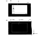
図4(A)は、使用者に視認される虚像と外界像の一例を示す説明図である。また、図4(B)は、左遮光部272(及び右遮光部271)の透過率の設定の一例を示す図である。上述のようにして、頭部装着型表示装置100を装着した使用者の両眼に導かれた画像光GLが使用者の両眼の網膜に結像することにより、使用者は虚像を視認することができる。図4(A)に示すように、頭部装着型表示装置100の使用者の視野VR内には、虚像VIが表示される。
FIG. 4A is an explanatory diagram illustrating an example of a virtual image and an external image visually recognized by the user. FIG. 4B is a diagram illustrating an example of setting the transmittance of the left light shielding unit 272 (and the right light shielding unit 271). As described above, the image light GL guided to both eyes of the user wearing the head-mounted
ここで、図4(B)に示すように、左遮光部272(及び右遮光部271)の領域A1と領域A2の透過率Tがともに100%に設定(制御)された場合には、図4(A)に示すように、視野VRの内の虚像VIが表示された部分については、虚像VIの背後に外景SC(第1の領域A1を透過した外界光GL’により形成される外界像)が透けて見え、また、虚像VIが表示された部分以外についても、外景SC(第2の領域A2を透過した外界光GL’により形成される外界像)が見える。図4(A)に示す場合には、外景SCが視認し易くなるため、使用者が周囲の状況を確認でき、また、虚像VIとして動きの激しい動画を表示する場合であっても映像酔いになることを防止することができる。 Here, as shown in FIG. 4B, when the transmittances T of the area A1 and the area A2 of the left light shielding part 272 (and the right light shielding part 271) are both set (controlled) to 100%, As shown in FIG. 4A, for the portion of the visual field VR where the virtual image VI is displayed, the external scene SC (the external image formed by the external light GL ′ transmitted through the first region A1 is behind the virtual image VI. ) And the outside scene SC (the outside image formed by the outside light GL ′ that has passed through the second region A2) can be seen in areas other than the portion where the virtual image VI is displayed. In the case shown in FIG. 4 (A), the outside scene SC can be easily seen, so that the user can check the surrounding situation, and even when a moving image is displayed as a virtual image VI, the user is intoxicated. Can be prevented.
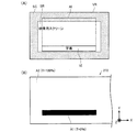
また、図5(B)に示すように、左遮光部272(及び右遮光部271)の領域A1の透過率Tが0%に設定され、領域A2の透過率Tが100%に設定された場合には、第1の領域A1において外界光が遮断されるため、図5(A)に示すように、視野VRの内の虚像VIが表示された部分については、外景SCは透けて見えず、虚像VIが表示された部分以外についてのみ、外景SC(第2の領域A2を透過した外界光GL’により形成される外界像)が見える。図5(A)に示す場合には、周囲に対する視野を確保しつつ、虚像VIを視認し易くすることができる。 Further, as shown in FIG. 5B, the transmittance T of the area A1 of the left light shielding part 272 (and the right light shielding part 271) is set to 0%, and the transmittance T of the area A2 is set to 100%. In this case, since the external light is blocked in the first region A1, as shown in FIG. 5A, the portion of the visual field VR where the virtual image VI is displayed cannot be seen through. Only outside the portion where the virtual image VI is displayed, the outside scene SC (the outside image formed by the outside light GL ′ transmitted through the second region A2) can be seen. In the case shown in FIG. 5A, it is possible to make the virtual image VI easily visible while ensuring a visual field with respect to the surroundings.
また、図6(B)に示すように、左遮光部272(及び右遮光部271)の領域A1と領域A2の透過率Tがともに0%に設定された場合には、第1の領域A1及び第2の領域A2において外界光が遮断されるため、図6(A)に示すように、視野VRの内の虚像VIが表示された部分については、外景SCは透けて見えず、虚像VIが表示された部分以外についても外景SCが見えなくなる。図6(A)に示す場合には、視野VRに虚像VIのみが表示されるため、使用者が没入感を感じ易くすることができる。 In addition, as shown in FIG. 6B, when the transmittances T of the area A1 and the area A2 of the left light shielding part 272 (and the right light shielding part 271) are both set to 0%, the first area A1. Since the external light is blocked in the second area A2, as shown in FIG. 6 (A), in the portion where the virtual image VI in the visual field VR is displayed, the external scene SC is not seen through, and the virtual image VI The outside scene SC can no longer be seen in areas other than where the is displayed. In the case shown in FIG. 6A, since only the virtual image VI is displayed in the visual field VR, the user can easily feel immersive.
本実施形態の頭部装着型表示装置100では、使用者は、操作部110を操作することで、左遮光部272及び右遮光部271の透過率を変更することができる。例えば、虚像VIの背後に見える外景SCが邪魔である場合には、左遮光部272及び右遮光部271の透過率を図5(B)或いは図6(B)に示すような設定とする操作を行って、虚像VIを見易くし、また、周囲の状況を確認したい場合や動きの激しい動画を視聴する場合には、左遮光部272及び右遮光部271の透過率を図4(B)或いは図5(B)に示すような設定とする操作を行って、外景SCを見易くすることができる。
In the head-mounted
また、遮光制御部192は、使用者が操作部110を操作することで起動されたアプリケーションの種類に応じて、左遮光部272及び右遮光部271の透過率を変更する制御を行ってもよい。例えば、虚像VIとして、その背後に見える外景SCがさほど邪魔にならないようなコンテンツを表示するアプリケーション(例えば、動画再生用のアプリケーション)が起動された場合に、左遮光部272及び右遮光部271の透過率を図4(B)に示すような設定とする制御を行う。また、虚像VIとして、その背後に見える外景SCが邪魔となるようなコンテンツを表示するアプリケーション(例えば、静止画やテキストを表示するアプリケーション、表示オブジェクトに対して操作を行うアプリケーション)が起動された場合に、左遮光部272及び右遮光部271の透過率を図5(B)或いは図6(B)に示すような設定とする制御を行う。
Further, the light
また、遮光制御部192は、検出部60からの検出データーに基づいて、左遮光部272及び右遮光部271の透過率を変更する制御を行ってもよい。例えば、検出部60からの検出データーに基づき、使用者の頭部が動いた(或いは、頭部が回転した)と判断した場合には、使用者が虚像VI以外の外界からの刺激に反応している(例えば、人に呼び掛けられた)と考えられるため、この場合に、左遮光部272及び右遮光部271の透過率を図4(B)或いは図5(B)に示すような設定として、外景SCを見易くする制御を行う。
Further, the light
また、遮光制御部192は、操作部110に対する何らかの操作が行われた場合には、使用者が虚像VIに集中していると考えられるため、この場合に、左遮光部272及び右遮光部271の透過率を図5(B)或いは図6(B)に示すような設定として、虚像VIを見易くする制御を行ってもよい。
In addition, since the user is considered to be concentrated on the virtual image VI when any operation on the
本発明は、上述した実施形態に限定されるものではなく、種々の変形が可能である。例えば、本発明は、実施形態で説明した構成と実質的に同一の構成(例えば、機能、方法及び結果が同一の構成、あるいは目的及び効果が同一の構成)を含む。また、本発明は、実施形態で説明した構成の本質的でない部分を置き換えた構成を含む。また、本発明は、実施形態で説明した構成と同一の作用効果を奏する構成又は同一の目的を達成することができる構成を含む。また、本発明は、実施形態で説明した構成に公知技術を付加した構成を含む。 The present invention is not limited to the above-described embodiments, and various modifications can be made. For example, the present invention includes configurations that are substantially the same as the configurations described in the embodiments (for example, configurations that have the same functions, methods, and results, or configurations that have the same objects and effects). In addition, the invention includes a configuration in which a non-essential part of the configuration described in the embodiment is replaced. In addition, the present invention includes a configuration that exhibits the same operational effects as the configuration described in the embodiment or a configuration that can achieve the same object. In addition, the invention includes a configuration in which a known technique is added to the configuration described in the embodiment.
例えば、上記実施形態では、制御部10と画像表示部20とを別体で構成する場合について説明したが、制御部10と画像表示部20とを一体化して頭部装着型表示装置100を構成してもよい。
For example, in the above-described embodiment, the case where the
また、上記実施形態では、遮光部(右遮光部271、左遮光部272)として透過型液晶パネル(液晶シャッター)を用いる場合について説明したが、本発明はこれに限られない。遮光部は、機械的な手段或いは光学的な手段を用いて光を遮ることができるものであれば、どのようなものを用いてもよい。例えば、遮光部をエレクトロクロミック素子で構成してもよい。
Moreover, although the said embodiment demonstrated the case where a transmissive liquid crystal panel (liquid crystal shutter) was used as a light-shielding part (the right light-shielding
また、上記実施形態では、遮光部の第1の領域A1を、反射部262aにおいて画像光と合成される外界光を透過させる領域とし、遮光部の第2の領域A2(第1の領域A1以外の領域)を、反射部262aにおいて画像光と合成されない外界光を透過させる領域とする場合について説明したが、本発明はこれに限られず、遮光部の第1の領域A1を、任意の大きさ及び位置の領域としてもよい。例えば、遮光部の第1の領域A1を、反射部262aにおいて画像光と合成される外界光の少なくとも一部を透過させる領域としてもよい。また、遮光部の第1の領域A1及び第2の領域A1の大きさ及び位置の少なくとも一方を変更可能に構成してもよい。
In the above embodiment, the first region A1 of the light shielding unit is a region that transmits external light combined with the image light in the
例えば、本発明に係る頭部装着型表示装置100を、映画館において映画鑑賞用に字幕を表示する装置として用いた場合には、図7(A)に示すように、使用者の視野VRの虚像表示領域AI(虚像を表示可能な領域)の下部に、虚像VIとして字幕を表示する。使用者は、外界像SCである映像用スクリーンSRを見ながら、虚像VIである字幕を見ることができる。このとき、図7(B)に示すように、左遮光部272(及び右遮光部271)の第1の領域A1を、虚像表示領域AIにおいて虚像VIとして字幕が表示される領域に対応して設定し、第1の領域A1の透過率Tを0%(或いは、0%≦T<100%)とし、第2の領域A2(第1の領域A1以外の領域)の透過率Tを100%とすることで、映像用スクリーンSRと重畳する字幕(虚像VI)を視認し易くしつつ、外界像SCである映像用スクリーンSRの大部分を視認させることができる。また、図7(A)に示すように外界像SCとして視認される映像用スクリーンSRと字幕(虚像VI)とが重複する位置関係である場合に、図7(B)に示すように第1の領域A1の透過率Tを低下させ、図8(A)に示すように外界像SCとして視認される映像用スクリーンSRと字幕(虚像VI)とが重複しない位置関係である場合には、図8(B)に示すように第1の領域A1の透過率Tを100%とする(又は、第1の領域A1の大きさを0とする)制御を行ってもよい。例えば、画像表示部20に、使用者の視野方向を撮像する撮像部(カメラ)を設けておき、遮光制御部192が、当該撮像部から出力された撮像画像中の映像用スクリーンSRの位置(及び面積)に基づいて、使用者の視野VRにおいて字幕(虚像VI)と映像用スクリーンSRが重複しているかを判断してもよい。また、検出部60からの検出データーに基づき上記位置関係を判断してもよい。
For example, when the head-mounted
また、上記実施形態では、画像光生成部を、液晶パネルとバックライトで構成し、生成した画像光を導光板によって使用者の眼に導くように構成する場合について説明したが、本発明は、これに限られない。例えば、図9に示すように、画像表示部20を、信号光を形成するとともに当該信号光を走査光SLとして射出する光射出部310と、走査光SLを受けて画像光PLを形成する被照射部材である虚像形成部320と、遮光部330とで構成してもよい。図9に示すように、光射出部310は、使用者の鼻NS周辺に配置され、虚像形成部320は、使用者の眼REの前方を覆うように配置されている。また、遮光部330は、虚像形成部320の表側の一部を覆うように設けられている。光射出部310は、画像に対応して変調された信号光を形成する信号光変調部311と、信号光を走査光SLとして虚像形成部320において2次元走査させる走査光学系312と、図示しない駆動制御回路を有する。信号光変調部311は、例えば、赤、青、黄色の各色光を発生する3つの光源と、各色光を合成して信号光を形成するダイクロイックミラーとで構成され、走査光学系312は、例えば、MEMSミラーで構成される。虚像形成部320は、透明基板上に半透過反射膜を有して構成されるハーフミラーであり、走査光学系312から照射された走査光SLを受け、これを反射することで虚像を形成し、使用者に視認させる。虚像形成部320は、虚像を形成するだけでなく、遮光部330を透過した外界光OLを透過させ、使用者が虚像と外界像とを同時に視認可能に構成されている。
In the above embodiment, the image light generation unit is configured by a liquid crystal panel and a backlight, and the generated image light is configured to be guided to the user's eyes by the light guide plate. It is not limited to this. For example, as shown in FIG. 9, the
また、画像光生成部(画像表示部20)を、3面以上の非軸対称な曲面を含むプリズム(導光プリズム)と、画像光を前記プリズムに入射させる投射レンズとで構成し、前記投射レンズを含む光学系を、前記プリズムの内部に中間像を形成するリレー光学系として構成してもよい。そして、画像光が前記プリズムの第3面、第1面、第2面の順に反射された後、第1面を透過して使用者に到達し、外界光が前記プリズムの第1面と第3面とを通過して使用者に到達するように構成してもよい。 The image light generation unit (image display unit 20) includes a prism (light guide prism) including three or more non-axisymmetric curved surfaces, and a projection lens that causes the image light to enter the prism, and the projection The optical system including the lens may be configured as a relay optical system that forms an intermediate image inside the prism. Then, after the image light is reflected in the order of the third surface, the first surface, and the second surface of the prism, it passes through the first surface and reaches the user, and the external light is transmitted to the first surface of the prism and the first surface. You may comprise so that it may reach a user through 3 surfaces.
また、導光部に画像光を入射させる光入射部と、導光部によって導かれた画像光を外部に射出させる光射出部のそれぞれに、反射型体積ホログラムを設けて画像光を回折反射させるように構成してもよい。 In addition, a reflective volume hologram is provided in each of the light incident part that causes the image light to enter the light guide part and the light emitting part that emits the image light guided by the light guide part to diffract and reflect the image light. You may comprise as follows.
10 制御部、12 点灯部、14 タッチパッド、16 十字キー、18 電源スイッチ、20 画像表示部、21 耳掛部、22 右表示駆動部、24 左表示駆動部、26 右光学像表示部、28 左光学像表示部、32 右イヤホン、34 左イヤホン、40 接続部、42 右コード、44 左コード、46 連結部材、48 本体コード、51,52 送信部、53,54 受信部、60 検出部、100 頭部装着型表示装置、110 操作部、120 記憶部、130 電源、160 画像処理部、170 音声処理部、180 インターフェイス、190 表示制御部、192 遮光制御部(制御部)、201 右バックライト制御部、202 左バックライト制御部、211 右LCD制御部、212 左LCD制御部、221 右バックライト、222 左バックライト、241 右LCD、242 左LCD、251 右投写光学系、252 左投写光学系、261 右導光板(虚像形成部)、262 左導光板(虚像形成部)、262a 反射部、262b 半透過反射面、271 右遮光部(遮光部)、272 左遮光部(遮光部)、310 光射出部、311 信号光変調部、312 走査光学系、320 虚像形成部、330 遮光部、A1 第1の領域、A2 第2の領域、SC 外景(外界像)、VI 虚像 DESCRIPTION OF SYMBOLS 10 Control part, 12 Lighting part, 14 Touch pad, 16 Cross key, 18 Power switch, 20 Image display part, 21 Ear hook part, 22 Right display drive part, 24 Left display drive part, 26 Right optical image display part, 28 Left optical image display unit, 32 right earphone, 34 left earphone, 40 connection unit, 42 right cord, 44 left cord, 46 connecting member, 48 body cord, 51, 52 transmission unit, 53, 54 reception unit, 60 detection unit, 100 head-mounted display device, 110 operation unit, 120 storage unit, 130 power supply, 160 image processing unit, 170 sound processing unit, 180 interface, 190 display control unit, 192 shading control unit (control unit), 201 right backlight Control unit, 202 Left backlight control unit, 211 Right LCD control unit, 212 Left LCD control unit, 221 Right backlight 222 Left backlight, 241 Right LCD, 242 Left LCD, 251 Right projection optical system, 252 Left projection optical system, 261 Right light guide plate (virtual image forming portion), 262 Left light guide plate (virtual image forming portion), 262a Reflector, 262b transflective surface, 271 right light shielding part (light shielding part), 272 left light shielding part (light shielding part), 310 light emitting part, 311 signal light modulating part, 312 scanning optical system, 320 virtual image forming part, 330 light shielding part, A1 1st area, A2 2nd area, SC outside scene (outside image), VI virtual image
Claims (7)
画像を表す画像光を生成する画像光生成部と、外界光を所与の透過率で透過させる遮光部と、前記遮光部を透過した外界光を透過させるとともに前記画像光により使用者の眼に前記虚像を形成する虚像形成部とを有し、使用者が前記虚像と外界像とを視認可能に構成された画像表示部と、
前記遮光部の透過率を変更する制御を行う制御部と、を備え、
前記画像表示部は、前記使用者の視野方向を撮像する撮像部を有し、
前記遮光部は、前記画像光と重畳する外界光を透過させる第1の領域と、前記画像光と重畳されない外界光を透過させる第2の領域と、を有し、
前記撮像部から出力された撮像画像中の外界像の位置に基づいて、前記外界像と前記虚像とが重複するかを判定し、
前記遮光部の第1の領域の透過率と、前記第2の領域の透過率とを前記外界像と前記虚像とが重複するかしないかの相互の位置関係に応じて制御する、頭部装着型表示装置。 A head-mounted display device that allows a user to visually recognize a virtual image while being mounted on the user's head,
An image light generation unit that generates image light representing an image, a light shielding unit that transmits external light at a given transmittance, and transmits external light that has passed through the light shielding unit, and is transmitted to the user's eyes by the image light. An image display unit that includes a virtual image forming unit that forms the virtual image, and is configured so that a user can visually recognize the virtual image and the external image;
A control unit that performs control to change the transmittance of the light shielding unit,
The image display unit has an imaging unit that captures the visual field direction of the user,
The light shielding portion includes a first region that transmits external light that is superimposed on the image light, and a second region that transmits external light that is not superimposed on the image light,
Based on the position of the external image in the captured image output from the imaging unit, determine whether the external image and the virtual image overlap,
Head mounted for controlling the transmittance of the first region of the light shielding unit and the transmittance of the second region according to the mutual positional relationship of whether or not the external image and the virtual image overlap each other. Type display device.
画像を表す画像光を生成する画像光生成部と、外界光を所与の透過率で透過させる遮光部と、前記遮光部を透過した外界光を透過させるとともに前記画像光により使用者の眼に前記虚像を形成する虚像形成部とを有し、使用者が前記虚像と外界像とを視認可能に構成された画像表示部と、
前記画像表示部に設けられ、使用者の頭部の動きを検出する検出部と、
前記検出部で検出された検出データーに基づいて、前記遮光部の透過率を変更する制御を行う制御部と、を備え、
前記遮光部は、前記画像光と重畳する外界光を透過させる第1の領域と、前記画像光と重畳されない外界光を透過させる第2の領域と、を有し、
前記検出部からの検出データーに基づいて、前記外界像と前記虚像とが重複するかを判定し、
前記遮光部の第1の領域の透過率と、前記第2の領域の透過率とを前記外界像と前記虚像とが重複するかしないかの相互の位置関係に応じて制御する、頭部装着型表示装置。 A head-mounted display device that allows a user to visually recognize a virtual image while being mounted on the user's head,
An image light generation unit that generates image light representing an image, a light shielding unit that transmits external light at a given transmittance, and transmits external light that has passed through the light shielding unit, and is transmitted to the user's eyes by the image light. An image display unit that includes a virtual image forming unit that forms the virtual image, and is configured so that a user can visually recognize the virtual image and the external image;
A detection unit provided in the image display unit for detecting movement of the user's head;
A control unit that performs control to change the transmittance of the light-shielding unit based on detection data detected by the detection unit,
The light shielding portion includes a first region that transmits external light that is superimposed on the image light, and a second region that transmits external light that is not superimposed on the image light,
Based on the detection data from the detection unit, determine whether the external image and the virtual image overlap,
Head mounted for controlling the transmittance of the first region of the light shielding unit and the transmittance of the second region according to the mutual positional relationship of whether or not the external image and the virtual image overlap each other. Type display device.
前記制御部は、
前記外界像と前記虚像とが重複する位置関係である場合に、外界を見やすくするように前記第2の領域の透過率を制御するとともに、前記第1の領域の透過率を前記第2の領域の透過率よりも低下させ、
前記外界像と前記虚像とが重複しない位置関係である場合に、外界を見やすくするように前記第1の領域の透過率と、前記第2の領域の透過率とを制御する、頭部装着型表示装置。 The head-mounted display device according to claim 1 or 2,
The controller is
In the case where the external image and the virtual image overlap each other, the transmittance of the second region is controlled so that the external world can be easily seen, and the transmittance of the first region is set to the second region. Lower than the transmittance of
A head-mounted type that controls the transmittance of the first region and the transmittance of the second region so as to make the outside world easier to see when the external image and the virtual image have a positional relationship that does not overlap. Display device.
前記外界像は、映像用スクリーンであり、前記虚像は、前記外界像としての前記映像用スクリーンに重畳して表示される字幕である、頭部装着型表示装置。 The head-mounted display device according to any one of claims 1 to 3,
The head-mounted display device, wherein the external image is a video screen, and the virtual image is a caption displayed superimposed on the video screen as the external image.
前記制御部は、
前記遮光部の前記第1の領域の透過率と、前記第2の領域の透過率とを、前記字幕の大きさ、前記字幕の位置に応じて制御する、頭部装着型表示装置。 The head-mounted display device according to claim 4,
The controller is
A head-mounted display device that controls the transmittance of the first region and the transmittance of the second region of the light shielding unit according to the size of the caption and the position of the caption.
画像を表す画像光を生成する画像光生成部と、外界光を所与の透過率で透過させる遮光部と、前記遮光部を透過した外界光を透過させるとともに前記画像光により使用者の眼に前記虚像を形成する虚像形成部とを有し、使用者が前記虚像と外界像とを視認可能に構成された画像表示部と、
前記画像表示部に設けられ、使用者の頭部の動きを検出する検出部と、
前記検出部で検出された検出データーに基づいて、前記遮光部の透過率を変更する制御を行う制御部と、を備え、
前記遮光部は、前記画像光と重畳する外界光を透過させる第1の領域と、前記画像光と重畳されない外界光を透過させる第2の領域と、を有し、
前記検出部からの検出データーに基づいて、前記使用者の頭部が動いたかを判定し、
前記使用者の頭部が動いた場合に、少なくとも外界を見やすくするように前記第2の領域の透過率を制御する、頭部装着型表示装置。 A head-mounted display device that allows a user to visually recognize a virtual image while being mounted on the user's head,
An image light generation unit that generates image light representing an image, a light shielding unit that transmits external light at a given transmittance, and transmits external light that has passed through the light shielding unit, and is transmitted to the user's eyes by the image light. An image display unit that includes a virtual image forming unit that forms the virtual image, and is configured so that a user can visually recognize the virtual image and the external image;
A detection unit provided in the image display unit for detecting movement of the user's head;
A control unit that performs control to change the transmittance of the light-shielding unit based on detection data detected by the detection unit,
The light shielding portion includes a first region that transmits external light that is superimposed on the image light, and a second region that transmits external light that is not superimposed on the image light,
Based on the detection data from the detection unit, determine whether the user's head has moved,
A head-mounted display device that controls the transmittance of the second region so that at least the outside is easily visible when the user's head moves.
前記制御部は、前記第1の領域の大きさ及び位置の少なくとも一方を変更する制御を行う、頭部装着型表示装置。 The head-mounted display device according to any one of claims 1 to 6,
The head-mounted display device, wherein the control unit performs control to change at least one of a size and a position of the first region.
Priority Applications (4)
| Application Number | Priority Date | Filing Date | Title |
|---|---|---|---|
| JP2012083634A JP6060512B2 (en) | 2012-04-02 | 2012-04-02 | Head-mounted display device |
| US13/852,360 US9046686B2 (en) | 2012-04-02 | 2013-03-28 | Head-mount type display device |
| CN201310112099.XA CN103364953B (en) | 2012-04-02 | 2013-04-02 | Head-mount type display unit |
| US14/699,852 US9269193B2 (en) | 2012-04-02 | 2015-04-29 | Head-mount type display device |
Applications Claiming Priority (1)
| Application Number | Priority Date | Filing Date | Title |
|---|---|---|---|
| JP2012083634A JP6060512B2 (en) | 2012-04-02 | 2012-04-02 | Head-mounted display device |
Publications (3)
| Publication Number | Publication Date |
|---|---|
| JP2013214856A JP2013214856A (en) | 2013-10-17 |
| JP2013214856A5 JP2013214856A5 (en) | 2015-05-07 |
| JP6060512B2 true JP6060512B2 (en) | 2017-01-18 |
Family
ID=49234195
Family Applications (1)
| Application Number | Title | Priority Date | Filing Date |
|---|---|---|---|
| JP2012083634A Active JP6060512B2 (en) | 2012-04-02 | 2012-04-02 | Head-mounted display device |
Country Status (3)
| Country | Link |
|---|---|
| US (2) | US9046686B2 (en) |
| JP (1) | JP6060512B2 (en) |
| CN (1) | CN103364953B (en) |
Cited By (1)
| Publication number | Priority date | Publication date | Assignee | Title |
|---|---|---|---|---|
| KR20210158526A (en) * | 2020-06-24 | 2021-12-31 | 주식회사 레티널 | Lightweight optical device for augmented reality using state switchable optical element |
Families Citing this family (75)
| Publication number | Priority date | Publication date | Assignee | Title |
|---|---|---|---|---|
| US9229233B2 (en) | 2014-02-11 | 2016-01-05 | Osterhout Group, Inc. | Micro Doppler presentations in head worn computing |
| US9298007B2 (en) | 2014-01-21 | 2016-03-29 | Osterhout Group, Inc. | Eye imaging in head worn computing |
| US9400390B2 (en) | 2014-01-24 | 2016-07-26 | Osterhout Group, Inc. | Peripheral lighting for head worn computing |
| US9952664B2 (en) | 2014-01-21 | 2018-04-24 | Osterhout Group, Inc. | Eye imaging in head worn computing |
| US9965681B2 (en) | 2008-12-16 | 2018-05-08 | Osterhout Group, Inc. | Eye imaging in head worn computing |
| US9715112B2 (en) * | 2014-01-21 | 2017-07-25 | Osterhout Group, Inc. | Suppression of stray light in head worn computing |
| EP2808725B1 (en) | 2012-01-24 | 2018-09-26 | Sony Corporation | Head-mounted display device with a light-shielding member |
| JP6060512B2 (en) * | 2012-04-02 | 2017-01-18 | セイコーエプソン株式会社 | Head-mounted display device |
| JP6145966B2 (en) | 2012-05-09 | 2017-06-14 | ソニー株式会社 | Display device |
| JP6123342B2 (en) | 2013-02-20 | 2017-05-10 | ソニー株式会社 | Display device |
| JP2015027015A (en) * | 2013-07-29 | 2015-02-05 | ソニー株式会社 | Information presentation device and information processing system |
| KR102153599B1 (en) | 2013-11-18 | 2020-09-08 | 삼성전자주식회사 | Head mounted display apparatus and method for changing a light transmittance |
| US9939934B2 (en) | 2014-01-17 | 2018-04-10 | Osterhout Group, Inc. | External user interface for head worn computing |
| US9841599B2 (en) | 2014-06-05 | 2017-12-12 | Osterhout Group, Inc. | Optical configurations for head-worn see-through displays |
| US10191279B2 (en) | 2014-03-17 | 2019-01-29 | Osterhout Group, Inc. | Eye imaging in head worn computing |
| US9829707B2 (en) | 2014-08-12 | 2017-11-28 | Osterhout Group, Inc. | Measuring content brightness in head worn computing |
| US9746686B2 (en) | 2014-05-19 | 2017-08-29 | Osterhout Group, Inc. | Content position calibration in head worn computing |
| US9299194B2 (en) | 2014-02-14 | 2016-03-29 | Osterhout Group, Inc. | Secure sharing in head worn computing |
| US9594246B2 (en) | 2014-01-21 | 2017-03-14 | Osterhout Group, Inc. | See-through computer display systems |
| US11103122B2 (en) | 2014-07-15 | 2021-08-31 | Mentor Acquisition One, Llc | Content presentation in head worn computing |
| US10684687B2 (en) | 2014-12-03 | 2020-06-16 | Mentor Acquisition One, Llc | See-through computer display systems |
| US9575321B2 (en) | 2014-06-09 | 2017-02-21 | Osterhout Group, Inc. | Content presentation in head worn computing |
| US10254856B2 (en) | 2014-01-17 | 2019-04-09 | Osterhout Group, Inc. | External user interface for head worn computing |
| US10649220B2 (en) | 2014-06-09 | 2020-05-12 | Mentor Acquisition One, Llc | Content presentation in head worn computing |
| US20160019715A1 (en) | 2014-07-15 | 2016-01-21 | Osterhout Group, Inc. | Content presentation in head worn computing |
| US9753288B2 (en) | 2014-01-21 | 2017-09-05 | Osterhout Group, Inc. | See-through computer display systems |
| US9740280B2 (en) | 2014-01-21 | 2017-08-22 | Osterhout Group, Inc. | Eye imaging in head worn computing |
| US9494800B2 (en) | 2014-01-21 | 2016-11-15 | Osterhout Group, Inc. | See-through computer display systems |
| US9532715B2 (en) | 2014-01-21 | 2017-01-03 | Osterhout Group, Inc. | Eye imaging in head worn computing |
| US11487110B2 (en) | 2014-01-21 | 2022-11-01 | Mentor Acquisition One, Llc | Eye imaging in head worn computing |
| US9836122B2 (en) | 2014-01-21 | 2017-12-05 | Osterhout Group, Inc. | Eye glint imaging in see-through computer display systems |
| US11737666B2 (en) | 2014-01-21 | 2023-08-29 | Mentor Acquisition One, Llc | Eye imaging in head worn computing |
| US9766463B2 (en) | 2014-01-21 | 2017-09-19 | Osterhout Group, Inc. | See-through computer display systems |
| US9651788B2 (en) | 2014-01-21 | 2017-05-16 | Osterhout Group, Inc. | See-through computer display systems |
| US11669163B2 (en) | 2014-01-21 | 2023-06-06 | Mentor Acquisition One, Llc | Eye glint imaging in see-through computer display systems |
| US20150205135A1 (en) | 2014-01-21 | 2015-07-23 | Osterhout Group, Inc. | See-through computer display systems |
| US9651784B2 (en) | 2014-01-21 | 2017-05-16 | Osterhout Group, Inc. | See-through computer display systems |
| US11892644B2 (en) | 2014-01-21 | 2024-02-06 | Mentor Acquisition One, Llc | See-through computer display systems |
| US9846308B2 (en) | 2014-01-24 | 2017-12-19 | Osterhout Group, Inc. | Haptic systems for head-worn computers |
| US20150241964A1 (en) | 2014-02-11 | 2015-08-27 | Osterhout Group, Inc. | Eye imaging in head worn computing |
| US9401540B2 (en) | 2014-02-11 | 2016-07-26 | Osterhout Group, Inc. | Spatial location presentation in head worn computing |
| JP6391952B2 (en) * | 2014-03-17 | 2018-09-19 | ソニー株式会社 | Display device and optical device |
| US20160187651A1 (en) | 2014-03-28 | 2016-06-30 | Osterhout Group, Inc. | Safety for a vehicle operator with an hmd |
| US9651787B2 (en) | 2014-04-25 | 2017-05-16 | Osterhout Group, Inc. | Speaker assembly for headworn computer |
| US10853589B2 (en) | 2014-04-25 | 2020-12-01 | Mentor Acquisition One, Llc | Language translation with head-worn computing |
| US10663740B2 (en) | 2014-06-09 | 2020-05-26 | Mentor Acquisition One, Llc | Content presentation in head worn computing |
| US9995933B2 (en) * | 2014-06-24 | 2018-06-12 | Microsoft Technology Licensing, Llc | Display devices with transmittance compensation mask |
| CN107076992A (en) * | 2014-10-03 | 2017-08-18 | 精工爱普生株式会社 | It is adapted to the head-mounted display apparatus of environment |
| US9684172B2 (en) | 2014-12-03 | 2017-06-20 | Osterhout Group, Inc. | Head worn computer display systems |
| USD751552S1 (en) | 2014-12-31 | 2016-03-15 | Osterhout Group, Inc. | Computer glasses |
| JP6528263B2 (en) * | 2015-01-27 | 2019-06-12 | 国立大学法人 名古屋工業大学 | Head mounted display |
| US20160239985A1 (en) | 2015-02-17 | 2016-08-18 | Osterhout Group, Inc. | See-through computer display systems |
| JP6892213B2 (en) | 2015-04-30 | 2021-06-23 | ソニーグループ株式会社 | Display device and initial setting method of display device |
| US10109110B2 (en) | 2015-06-29 | 2018-10-23 | International Business Machines Corporation | Reality augmentation to eliminate, or de-emphasize, selected portions of base image |
| EP3113158A1 (en) * | 2015-07-03 | 2017-01-04 | Nokia Technologies Oy | Control of selective actuation of a light filter array |
| JP6630370B2 (en) * | 2015-07-30 | 2020-01-15 | シェンジェン ロイオル テクノロジーズ カンパニー リミテッドShenzhen Royole Technologies Co., Ltd. | Head mounted electronic devices |
| JP6306552B2 (en) * | 2015-10-13 | 2018-04-04 | 株式会社タダノ | Remote control device and guidance system |
| US9880441B1 (en) | 2016-09-08 | 2018-01-30 | Osterhout Group, Inc. | Electrochromic systems for head-worn computer systems |
| US9826299B1 (en) | 2016-08-22 | 2017-11-21 | Osterhout Group, Inc. | Speaker systems for head-worn computer systems |
| CN107272319A (en) * | 2016-04-07 | 2017-10-20 | 中强光电股份有限公司 | Projection arrangement and image projecting method |
| GB2551396B (en) | 2016-06-17 | 2018-10-10 | Imagination Tech Ltd | Augmented reality occlusion |
| IL247360B (en) | 2016-08-18 | 2021-09-30 | Veeride Ltd | Augmented reality apparatus and method |
| IL301297B1 (en) * | 2016-11-16 | 2024-04-01 | Magic Leap Inc | Multi-resolution display assembly for head-mounted display systems |
| KR20240009545A (en) * | 2016-12-22 | 2024-01-22 | 매직 립, 인코포레이티드 | Systems and methods for manipulating light from ambient light sources |
| JP6998047B2 (en) * | 2017-02-09 | 2022-01-18 | 株式会社パーシテック | Shielded wearable computer |
| JP6919222B2 (en) * | 2017-02-27 | 2021-08-18 | セイコーエプソン株式会社 | Display device and control method of display device |
| WO2018232184A1 (en) * | 2017-06-14 | 2018-12-20 | Hadal, Inc. | Systems and methods for virtual reality motion sickness prevention |
| WO2019077975A1 (en) | 2017-10-16 | 2019-04-25 | コニカミノルタ株式会社 | Video display device and optical see-through display |
| JP7235146B2 (en) * | 2018-03-16 | 2023-03-08 | 株式会社リコー | Head-mounted display and display system |
| JP2022532688A (en) * | 2019-05-06 | 2022-07-19 | ルーマス リミテッド | A transparent light guide for viewing scenes and near-eye displays |
| CN110728934B (en) * | 2019-09-19 | 2023-04-07 | 中国第一汽车股份有限公司 | Holographic projection brightness adjusting system and method, vehicle and storage medium |
| JP2020058051A (en) * | 2019-12-05 | 2020-04-09 | マクセル株式会社 | Broadcast receiver and application control method |
| CN111273445A (en) * | 2020-01-21 | 2020-06-12 | 华为技术有限公司 | AR display device, transmittance adjusting method thereof and wearable system |
| JP6862641B2 (en) * | 2020-06-05 | 2021-04-21 | ソニーグループ株式会社 | Display device and initial setting method of display device |
| CN115240820A (en) * | 2021-04-23 | 2022-10-25 | 中强光电股份有限公司 | Wearable device and method for adjusting display state based on environment |
Family Cites Families (28)
| Publication number | Priority date | Publication date | Assignee | Title |
|---|---|---|---|---|
| JP3326820B2 (en) * | 1992-08-28 | 2002-09-24 | ソニー株式会社 | Visual device |
| JPH10221637A (en) * | 1997-02-10 | 1998-08-21 | Olympus Optical Co Ltd | Head-mounted image display device |
| JPH11346336A (en) * | 1998-06-01 | 1999-12-14 | Fuji Electric Co Ltd | Eyeglass type head mount display device |
| CN2408476Y (en) * | 1999-08-11 | 2000-11-29 | 张书博 | Glasses type displayer |
| JP3735086B2 (en) * | 2002-06-20 | 2006-01-11 | ウエストユニティス株式会社 | Work guidance system |
| US7774075B2 (en) * | 2002-11-06 | 2010-08-10 | Lin Julius J Y | Audio-visual three-dimensional input/output |
| JP2005164978A (en) * | 2003-12-03 | 2005-06-23 | Nikon Corp | Head mounted display |
| JP2005172851A (en) * | 2003-12-05 | 2005-06-30 | Sony Corp | Image display apparatus |
| WO2005111693A1 (en) | 2004-05-17 | 2005-11-24 | Olympus Corporation | Head-mounted type image display device |
| JP4766913B2 (en) | 2004-05-17 | 2011-09-07 | オリンパス株式会社 | Head-mounted image display device |
| CN101272727B (en) * | 2005-09-27 | 2011-09-07 | 潘尼公司 | A device for controlling an external unit |
| JP4802806B2 (en) * | 2006-03-28 | 2011-10-26 | ブラザー工業株式会社 | Image display device |
| US7828434B2 (en) * | 2006-08-31 | 2010-11-09 | Nike, Inc. | Zone switched sports training eyewear |
| JP5309448B2 (en) * | 2007-01-26 | 2013-10-09 | ソニー株式会社 | Display device and display method |
| US7893890B2 (en) * | 2007-03-05 | 2011-02-22 | The Boeing Company | Electrically dimmable combiner optics for head-up display |
| JP5151207B2 (en) * | 2007-03-28 | 2013-02-27 | 株式会社ニコン | Display device |
| EP2093603B1 (en) * | 2008-02-19 | 2011-08-17 | Saab Ab | Head-up display with brightness control |
| JP2009244869A (en) * | 2008-03-11 | 2009-10-22 | Panasonic Corp | Display apparatus, display method, goggle-type head-mounted display, and vehicle |
| DE102008049407A1 (en) * | 2008-09-29 | 2010-04-01 | Carl Zeiss Ag | Display device and display method |
| JP5402293B2 (en) * | 2009-06-22 | 2014-01-29 | ソニー株式会社 | Head-mounted display and image display method in head-mounted display |
| JP5240222B2 (en) * | 2010-03-26 | 2013-07-17 | 株式会社デンソー | Head-up display device |
| US20120033195A1 (en) * | 2010-08-05 | 2012-02-09 | L-3 Communications Eotech, Inc. | Multipurpose Aiming Sight with Head-Up Display Module |
| US8941559B2 (en) * | 2010-09-21 | 2015-01-27 | Microsoft Corporation | Opacity filter for display device |
| US8605009B2 (en) * | 2010-12-05 | 2013-12-10 | Ford Global Technologies, Llc | In-vehicle display management system |
| US20120188148A1 (en) * | 2011-01-24 | 2012-07-26 | Microvision, Inc. | Head Mounted Meta-Display System |
| US20120249587A1 (en) * | 2011-04-04 | 2012-10-04 | Anderson Glen J | Keyboard avatar for heads up display (hud) |
| US8692739B2 (en) * | 2011-09-22 | 2014-04-08 | GM Global Technology Operations LLC | Dynamic information presentation on full windshield head-up display |
| JP6060512B2 (en) * | 2012-04-02 | 2017-01-18 | セイコーエプソン株式会社 | Head-mounted display device |
-
2012
- 2012-04-02 JP JP2012083634A patent/JP6060512B2/en active Active
-
2013
- 2013-03-28 US US13/852,360 patent/US9046686B2/en active Active
- 2013-04-02 CN CN201310112099.XA patent/CN103364953B/en active Active
-
2015
- 2015-04-29 US US14/699,852 patent/US9269193B2/en active Active
Cited By (2)
| Publication number | Priority date | Publication date | Assignee | Title |
|---|---|---|---|---|
| KR20210158526A (en) * | 2020-06-24 | 2021-12-31 | 주식회사 레티널 | Lightweight optical device for augmented reality using state switchable optical element |
| KR102631786B1 (en) * | 2020-06-24 | 2024-01-31 | 주식회사 레티널 | Lightweight optical device for augmented reality using state switchable optical element |
Also Published As
| Publication number | Publication date |
|---|---|
| US20130257691A1 (en) | 2013-10-03 |
| CN103364953A (en) | 2013-10-23 |
| CN103364953B (en) | 2017-03-01 |
| JP2013214856A (en) | 2013-10-17 |
| US20150243087A1 (en) | 2015-08-27 |
| US9046686B2 (en) | 2015-06-02 |
| US9269193B2 (en) | 2016-02-23 |
Similar Documents
| Publication | Publication Date | Title |
|---|---|---|
| JP6060512B2 (en) | Head-mounted display device | |
| JP6066037B2 (en) | Head-mounted display device | |
| JP5958689B2 (en) | Head-mounted display device | |
| JP6089705B2 (en) | Display device and control method of display device | |
| JP6232763B2 (en) | Head-mounted display device and method for controlling head-mounted display device | |
| US9836120B2 (en) | Display device, method of controlling the same, and computer program | |
| US20150168729A1 (en) | Head mounted display device | |
| JP6094305B2 (en) | Head-mounted display device and method for controlling head-mounted display device | |
| JP6075083B2 (en) | Head-mounted display device and method for controlling head-mounted display device | |
| JP2016142887A (en) | Head-mounted display device and control method of the same, and computer program | |
| JP2016024208A (en) | Display device, method for controlling display device, and program | |
| JP6268778B2 (en) | Head-mounted display device and method for controlling head-mounted display device | |
| JP6575117B2 (en) | Display device, display device control method, and program | |
| JP6428024B2 (en) | Display device, display device control method, and program | |
| JP6252002B2 (en) | Head-mounted display device and method for controlling head-mounted display device | |
| US20150168728A1 (en) | Head mounted display device | |
| JP2017079389A (en) | Display device, display device control method, and program | |
| JP6582374B2 (en) | Display device, control method therefor, and computer program | |
| JP6136162B2 (en) | Head-mounted display device and method for controlling head-mounted display device | |
| JP6273677B2 (en) | Head-mounted display device and method for controlling head-mounted display device | |
| JP6304415B2 (en) | Head-mounted display device and method for controlling head-mounted display device | |
| JP2016034091A (en) | Display device, control method of the same and program | |
| JP6375662B2 (en) | Head-mounted display device | |
| JP6268704B2 (en) | Display device, display device control method, and program | |
| JP2016031373A (en) | Display device, display method, display system, and program |
Legal Events
| Date | Code | Title | Description |
|---|---|---|---|
| RD04 | Notification of resignation of power of attorney |
Free format text: JAPANESE INTERMEDIATE CODE: A7424 Effective date: 20150107 |
|
| A521 | Request for written amendment filed |
Free format text: JAPANESE INTERMEDIATE CODE: A523 Effective date: 20150320 |
|
| A621 | Written request for application examination |
Free format text: JAPANESE INTERMEDIATE CODE: A621 Effective date: 20150320 |
|
| A977 | Report on retrieval |
Free format text: JAPANESE INTERMEDIATE CODE: A971007 Effective date: 20151217 |
|
| A131 | Notification of reasons for refusal |
Free format text: JAPANESE INTERMEDIATE CODE: A131 Effective date: 20151222 |
|
| A521 | Request for written amendment filed |
Free format text: JAPANESE INTERMEDIATE CODE: A523 Effective date: 20160219 |
|
| RD04 | Notification of resignation of power of attorney |
Free format text: JAPANESE INTERMEDIATE CODE: A7424 Effective date: 20160609 |
|
| A131 | Notification of reasons for refusal |
Free format text: JAPANESE INTERMEDIATE CODE: A131 Effective date: 20160614 |
|
| RD03 | Notification of appointment of power of attorney |
Free format text: JAPANESE INTERMEDIATE CODE: A7423 Effective date: 20160617 |
|
| A521 | Request for written amendment filed |
Free format text: JAPANESE INTERMEDIATE CODE: A523 Effective date: 20160803 |
|
| TRDD | Decision of grant or rejection written | ||
| A01 | Written decision to grant a patent or to grant a registration (utility model) |
Free format text: JAPANESE INTERMEDIATE CODE: A01 Effective date: 20161115 |
|
| A61 | First payment of annual fees (during grant procedure) |
Free format text: JAPANESE INTERMEDIATE CODE: A61 Effective date: 20161128 |
|
| R150 | Certificate of patent or registration of utility model |
Ref document number: 6060512 Country of ref document: JP Free format text: JAPANESE INTERMEDIATE CODE: R150 |