JP6057251B2 - Particle sorting apparatus and particle sorting method - Google Patents
Particle sorting apparatus and particle sorting method Download PDFInfo
- Publication number
- JP6057251B2 JP6057251B2 JP2012198961A JP2012198961A JP6057251B2 JP 6057251 B2 JP6057251 B2 JP 6057251B2 JP 2012198961 A JP2012198961 A JP 2012198961A JP 2012198961 A JP2012198961 A JP 2012198961A JP 6057251 B2 JP6057251 B2 JP 6057251B2
- Authority
- JP
- Japan
- Prior art keywords
- flow path
- particle
- separation
- channel
- density
- Prior art date
- Legal status (The legal status is an assumption and is not a legal conclusion. Google has not performed a legal analysis and makes no representation as to the accuracy of the status listed.)
- Expired - Fee Related
Links
Images


Classifications
-
- C—CHEMISTRY; METALLURGY
- C12—BIOCHEMISTRY; BEER; SPIRITS; WINE; VINEGAR; MICROBIOLOGY; ENZYMOLOGY; MUTATION OR GENETIC ENGINEERING
- C12M—APPARATUS FOR ENZYMOLOGY OR MICROBIOLOGY; APPARATUS FOR CULTURING MICROORGANISMS FOR PRODUCING BIOMASS, FOR GROWING CELLS OR FOR OBTAINING FERMENTATION OR METABOLIC PRODUCTS, i.e. BIOREACTORS OR FERMENTERS
- C12M47/00—Means for after-treatment of the produced biomass or of the fermentation or metabolic products, e.g. storage of biomass
- C12M47/04—Cell isolation or sorting
-
- B—PERFORMING OPERATIONS; TRANSPORTING
- B03—SEPARATION OF SOLID MATERIALS USING LIQUIDS OR USING PNEUMATIC TABLES OR JIGS; MAGNETIC OR ELECTROSTATIC SEPARATION OF SOLID MATERIALS FROM SOLID MATERIALS OR FLUIDS; SEPARATION BY HIGH-VOLTAGE ELECTRIC FIELDS
- B03B—SEPARATING SOLID MATERIALS USING LIQUIDS OR USING PNEUMATIC TABLES OR JIGS
- B03B5/00—Washing granular, powdered or lumpy materials; Wet separating
- B03B5/28—Washing granular, powdered or lumpy materials; Wet separating by sink-float separation
-
- B—PERFORMING OPERATIONS; TRANSPORTING
- B01—PHYSICAL OR CHEMICAL PROCESSES OR APPARATUS IN GENERAL
- B01L—CHEMICAL OR PHYSICAL LABORATORY APPARATUS FOR GENERAL USE
- B01L2300/00—Additional constructional details
- B01L2300/08—Geometry, shape and general structure
- B01L2300/0861—Configuration of multiple channels and/or chambers in a single devices
- B01L2300/0864—Configuration of multiple channels and/or chambers in a single devices comprising only one inlet and multiple receiving wells, e.g. for separation, splitting
-
- B—PERFORMING OPERATIONS; TRANSPORTING
- B01—PHYSICAL OR CHEMICAL PROCESSES OR APPARATUS IN GENERAL
- B01L—CHEMICAL OR PHYSICAL LABORATORY APPARATUS FOR GENERAL USE
- B01L3/00—Containers or dishes for laboratory use, e.g. laboratory glassware; Droppers
- B01L3/50—Containers for the purpose of retaining a material to be analysed, e.g. test tubes
- B01L3/502—Containers for the purpose of retaining a material to be analysed, e.g. test tubes with fluid transport, e.g. in multi-compartment structures
- B01L3/5027—Containers for the purpose of retaining a material to be analysed, e.g. test tubes with fluid transport, e.g. in multi-compartment structures by integrated microfluidic structures, i.e. dimensions of channels and chambers are such that surface tension forces are important, e.g. lab-on-a-chip
- B01L3/502761—Containers for the purpose of retaining a material to be analysed, e.g. test tubes with fluid transport, e.g. in multi-compartment structures by integrated microfluidic structures, i.e. dimensions of channels and chambers are such that surface tension forces are important, e.g. lab-on-a-chip specially adapted for handling suspended solids or molecules independently from the bulk fluid flow, e.g. for trapping or sorting beads, for physically stretching molecules
-
- B—PERFORMING OPERATIONS; TRANSPORTING
- B03—SEPARATION OF SOLID MATERIALS USING LIQUIDS OR USING PNEUMATIC TABLES OR JIGS; MAGNETIC OR ELECTROSTATIC SEPARATION OF SOLID MATERIALS FROM SOLID MATERIALS OR FLUIDS; SEPARATION BY HIGH-VOLTAGE ELECTRIC FIELDS
- B03B—SEPARATING SOLID MATERIALS USING LIQUIDS OR USING PNEUMATIC TABLES OR JIGS
- B03B5/00—Washing granular, powdered or lumpy materials; Wet separating
- B03B5/28—Washing granular, powdered or lumpy materials; Wet separating by sink-float separation
- B03B5/30—Washing granular, powdered or lumpy materials; Wet separating by sink-float separation using heavy liquids or suspensions
- B03B5/36—Devices therefor, other than using centrifugal force
- B03B5/40—Devices therefor, other than using centrifugal force of trough type
- B03B2005/405—Devices therefor, other than using centrifugal force of trough type using horizontal currents
Landscapes
- Life Sciences & Earth Sciences (AREA)
- Engineering & Computer Science (AREA)
- Health & Medical Sciences (AREA)
- Wood Science & Technology (AREA)
- Zoology (AREA)
- Biotechnology (AREA)
- Bioinformatics & Cheminformatics (AREA)
- Organic Chemistry (AREA)
- Chemical & Material Sciences (AREA)
- Microbiology (AREA)
- Cell Biology (AREA)
- Sustainable Development (AREA)
- Molecular Biology (AREA)
- Biochemistry (AREA)
- General Engineering & Computer Science (AREA)
- General Health & Medical Sciences (AREA)
- Genetics & Genomics (AREA)
- Biomedical Technology (AREA)
- Separation Of Solids By Using Liquids Or Pneumatic Power (AREA)
- Apparatus Associated With Microorganisms And Enzymes (AREA)
Description
本発明は、粒子分別装置および粒子分別方法に関する。より詳細には、本発明は、細胞や化学合成された粒子等の、粒子毎に異なる密度を有する粒子群を密度差に従って分別することができる、マイクロメートルオーダーの流路を有する粒子分別装置および粒子分別方法に関する。 The present invention relates to a particle sorting apparatus and a particle sorting method. More specifically, the present invention relates to a particle sorting apparatus having a micrometer order flow path, which can sort particles having different densities for each particle, such as cells and chemically synthesized particles, according to the density difference. The present invention relates to a particle sorting method.
従来、細胞や化学合成された粒子等の、粒子毎に異なる性質の粒子群を分別する方法として、質量差により分別する方法、大きさにより分別する方法、密度差により分別する方法等、さまざまな方法が知られている。 Conventionally, there are various methods such as sorting by mass difference, sorting by size, sorting by density difference, etc., as a method for separating particles having different properties such as cells and chemically synthesized particles. The method is known.
例えば、異なる密度を有する粒子群を密度差により分別する方法としては、密度を調節した分離液を用いる沈殿平衡法や沈殿速度法、遠心分離法等の方法が挙げられる(特許文献1〜6を参照)。
For example, methods for separating particles having different densities based on density differences include methods such as a precipitation equilibrium method, a precipitation rate method, and a centrifugal method using a density-adjusted separation solution (see
また、粒子として細胞を分別する場合には、細胞等の生体試料が有する固有の免疫学的な特性である特異的な抗原抗体反応を活用し、磁気粒子や蛍光分子を結合させ、磁気細胞分別または蛍光活性化細胞分別のような細胞分別機により分別する方法が知られている。 In addition, when sorting cells as particles, a specific antigen-antibody reaction, which is a unique immunological characteristic of biological samples such as cells, is used to bind magnetic particles and fluorescent molecules to separate cells. Alternatively, a method of sorting using a cell sorter such as fluorescence activated cell sorting is known.
また、マイクロ流路を用い、電気泳動や凝集剤等を用いた方法も検討されている(特許文献7を参照)。また、マイクロ流路で超音波やピンチド流路を用いて密度に従って粒子群を分別する装置(非特許文献1,2を参照)および微粒子群を分級する方法(特許文献8,9を参照)が開発されている。
In addition, a method using electrophoresis, an aggregating agent, or the like using a microchannel has been studied (see Patent Document 7). Further, there are an apparatus (see Non-Patent
しかしながら、上述したような沈殿平衡法や沈殿速度法、遠心分離法等の方法を用いた場合では、分別した粒子の回収時に、ピペッティング等により目的の粒子を採取する操作を行うが、粒子のコンタミネーションを避けるため、分別する粒子群同士の距離を離す必要がある。そのため、粒子の移動距離を長くする必要があり、例えば遠心分離法では、より強い遠心力で、長時間の遠心分離を行うことが必要である。 However, in the case of using a method such as the precipitation equilibration method, the precipitation velocity method, or the centrifugal separation method as described above, an operation of collecting the target particles by pipetting or the like is performed at the time of collecting the separated particles. In order to avoid contamination, it is necessary to increase the distance between the particle groups to be separated. Therefore, it is necessary to lengthen the moving distance of the particles. For example, in the centrifugal separation method, it is necessary to perform centrifugation for a long time with a stronger centrifugal force.
そのため、例えば、粒子として体細胞を用いた場合には、体細胞に大きなストレスがかかるので、体細胞を用いた研究において、体細胞の細胞機能の低下が観測される場合や、十分な細胞応答を観察することができない場合が多いという問題がある。また、分別した粒子の回収時に、操作が煩雑で、多くの手間と時間がかかるという問題もある。 For this reason, for example, when somatic cells are used as particles, somatic cells are subject to great stress. Therefore, in studies using somatic cells, when cell function decline of somatic cells is observed, or sufficient cellular response There is a problem that it is often impossible to observe. In addition, there is also a problem that the operation is complicated at the time of collecting the separated particles, and it takes a lot of labor and time.
また、細胞分別機を用いた方法でも、高度な技術が要求され、操作が煩雑で、多くの手間と時間がかかるという問題がある。 In addition, even a method using a cell sorter has a problem that high technology is required, the operation is complicated, and it takes a lot of labor and time.
また、マイクロ流路を用い、電気泳動や凝集剤等を用いた方法や、マイクロ流路で超音波やピンチド流路を用いた方法では、以下の問題がある。すなわち、特許文献7に記載の方法は、粘度差により細胞を分離する手法であり、それゆえ、密度が互いに近い細胞の分別には向いていない。また、非特許文献1に記載の方法は、粒子のサイズと密度とを超音波により分別する手法であるが、体細胞を用いた場合は大きなストレスがかかる。非特許文献2に記載の方法は、粒子のサイズと密度とを分別するものであるが、分別の精度が十分でない。また、特許文献8,9に記載の方法は、例えば細胞のように、サイズが同じで密度等の性質が異なる粒子を対象としておらず、従って当該粒子を分別することはできない。
In addition, the method using electrophoresis or an aggregating agent using a micro flow channel, or the method using an ultrasonic wave or pinch flow channel in the micro flow channel has the following problems. That is, the method described in Patent Document 7 is a method of separating cells based on a difference in viscosity, and therefore is not suitable for sorting cells having similar densities. In addition, the method described in
このようなことから、粒子径(サイズ)が同じであっても、密度等の性質の異なる粒子群を低刺激で短時間に分別および回収する容易な方法が望まれている。 For this reason, there is a demand for an easy method for separating and collecting a group of particles having different properties such as density in a short time with low irritation even if the particle diameter (size) is the same.
本発明は、上記課題に鑑みてなされたものであり、その主たる目的は、粒子に重力負荷等の大きなストレスをかけずに、短時間で粒子群を分別することができ、分別した粒子群を容易に回収することができる粒子分別装置および粒子分別方法を提供することにある。 The present invention has been made in view of the above problems, and its main purpose is to classify the particle group in a short time without applying a large stress such as gravity load to the particle. An object of the present invention is to provide a particle sorting apparatus and a particle sorting method that can be easily collected.
上記課題を解決するために鋭意検討した結果、本発明者は、液体中において、体細胞や化学合成された粒子は、ストークスの式に従って、粒子径や密度が互いに異なる粒子群同士の挙動が異なることに着目し、これら粒子群を分別液が流れる流路において分別することができると考え、本発明に係る粒子分別装置および粒子分別方法を発明するに至った。 As a result of intensive studies to solve the above problems, the present inventors have found that somatic cells and chemically synthesized particles in liquids have different behaviors among particle groups having different particle diameters and densities according to the Stokes equation. In view of this, it was considered that these particle groups can be separated in the flow path through which the separation liquid flows, and the particle sorting apparatus and the particle sorting method according to the present invention have been invented.
すなわち、本発明に係る粒子分別装置は、上記課題を解決するために、分別液および少なくとも二種類の密度を有する粒子群が供給され、一定方向に分別液が流れる分別流路と、上記分別流路の上記分別液が流れる方向の少なくとも末端に接続された分岐部と、上記分岐部から上方向に向かって形成された第1流路と、上記分岐部から下方向に向かって形成された第2流路と、を少なくとも備えることを特徴としている。なお、ここにおける「下方向」とは「重力方向」であり、「上方向」とは「重力に逆らう方向」である。 That is, in order to solve the above problems, the particle separation device according to the present invention is supplied with a separation liquid and a particle group having at least two types of density, and the separation flow path through which the separation liquid flows in a fixed direction, and the separation flow. A branch portion connected to at least an end of the flow direction of the separation liquid, a first flow path formed upward from the branch portion, and a first channel formed downward from the branch portion. And at least two flow paths. Here, the “downward direction” is the “gravity direction”, and the “upward direction” is the “direction against gravity”.
上記の構成によれば、ストークスの式に従い、一定方向に流れる分別液中を、より高い密度を有する粒子群は、分別流路中の比較的下方向の領域を流れ、また、より低い密度を有する粒子群は、分別流路中の比較的上方向の領域を流れる。そのため、それぞれの粒子群が、上記分岐部から上方向または下方向に向かって形成された第1流路または第2流路に供給され、結果として、粒子径(サイズ)が同じであっても、密度の差に従って粒子群を分別することができる。 According to the above configuration, according to the Stokes equation, the particle group having a higher density flows in the separation liquid flowing in a certain direction, flows in a relatively lower region in the separation flow path, and has a lower density. The particle group having flows in a relatively upward region in the separation flow path. Therefore, each particle group is supplied to the first flow path or the second flow path formed upward or downward from the branch portion, and as a result, the particle diameter (size) is the same. The particle groups can be sorted according to the density difference.
これにより、粒子に大きなストレスをかけずに、短時間で粒子群を分別することができ、分別した粒子群を容易に回収することができる粒子分別装置を提供することができるという効果を奏する。 Thereby, there is an effect that it is possible to provide a particle sorting apparatus that can sort the particle group in a short time without applying a large stress to the particle and can easily collect the sorted particle group.
本発明に係る粒子分別装置は、上記分別流路が水平方向に形成されていることがより好ましい。上記の構成によれば、分別流路の流れに従って、粒子群を効率的に分別することができる。 In the particle sorting apparatus according to the present invention, the sorting channel is more preferably formed in the horizontal direction. According to said structure, a particle group can be sorted efficiently according to the flow of a sorting channel.
本発明に係る粒子分別装置は、上記分別液の密度が、上記第1流路に供給される低い密度を有する粒子群における粒子の最大密度より低く、且つ、上記第2流路に供給される高い密度を有する粒子群における粒子の最小密度より高いことがより好ましい。上記の構成によれば、第1流路に供給される低い密度を有する粒子群は、ストークスの式に従って全て浮上し、逆に、第2流路に供給される高い密度を有する粒子群は、全て沈降するため、より効率的に、より精確に粒子群を分別することができる粒子分別装置を提供することができる。 In the particle sorting apparatus according to the present invention, the density of the sorting liquid is lower than the maximum density of particles in the particle group having a low density supplied to the first flow path, and is supplied to the second flow path. More preferably, it is higher than the minimum density of the particles in the particle group having a high density. According to the above configuration, all the particle groups having a low density supplied to the first flow path float according to the Stokes equation, and conversely, the particle groups having a high density supplied to the second flow path are Since all settle, it is possible to provide a particle sorting apparatus capable of sorting the particle group more efficiently and more accurately.
本発明に係る粒子分別装置は、上記分別流路、分岐部、第1流路および第2流路を構成する溝が形成された第一部材、および、上記分別流路、分岐部、第1流路および第2流路を構成する溝が形成された第二部材を、上記溝で分別流路、分岐部、第1流路および第2流路が構成されるように重ね合わせてなることがより好ましい。上記の構成によれば、粒子分別装置をより簡単に形成することができる。また、分別流路、分岐部、第1流路および第2流路をより簡単に清掃することができる。 The particle sorting apparatus according to the present invention includes a sorting member, a branching portion, a first member in which grooves constituting the first channel and the second channel are formed, and the sorting channel, the branching portion, the first portion. The second member formed with the grooves constituting the flow path and the second flow path is overlapped so that the separation flow path, the branch portion, the first flow path, and the second flow path are formed by the grooves. Is more preferable. According to said structure, a particle sorting apparatus can be formed more easily. In addition, the separation flow path, the branch portion, the first flow path, and the second flow path can be more easily cleaned.
本発明に係る粒子分別装置は、上記分別流路、分岐部および第1流路を構成する溝が形成された第一部材、および、上記分別流路、分岐部および第2流路を構成する溝が形成された第二部材を、上記溝で分別流路、分岐部、第1流路および第2流路が構成されるように重ね合わせてなることがより好ましい。上記の構成によれば、粒子分別装置をより簡単に形成することができる。また、分別流路、分岐部、第1流路および第2流路をより簡単に清掃することができる。さらに、上記の構成によれば、第1流路および第2流路を分別流路から見て段違いに(二層構造に)形成することができるので、粒子分別装置の上下方向の幅(高さ)をより狭くすることができる。 The particle sorting apparatus according to the present invention forms a first member in which grooves constituting the sorting channel, the branching portion, and the first channel are formed, and the sorting channel, the branching portion, and the second channel. It is more preferable that the second member in which the groove is formed is overlapped so that the separation channel, the branch portion, the first channel, and the second channel are configured by the groove. According to said structure, a particle sorting apparatus can be formed more easily. In addition, the separation flow path, the branch portion, the first flow path, and the second flow path can be more easily cleaned. Furthermore, according to the above configuration, since the first flow path and the second flow path can be formed in a step difference (in a two-layer structure) when viewed from the separation flow path, the vertical width (high height) of the particle sorting apparatus is high. Can be made narrower.
本発明に係る粒子分別装置は、上記分別流路、分岐部、第1流路および第2流路を構成する溝が形成された第一部材、および、溝が形成されていない平滑な第二部材を、上記溝で分別流路、分岐部、第1流路および第2流路が構成されるように重ね合わせてなることがより好ましい。上記の構成によれば、粒子分別装置をさらに簡単に形成することができる。また、分別流路、分岐部、第1流路および第2流路をさらに簡単に清掃することができる。 The particle separation apparatus according to the present invention includes a separation member, a branching portion, a first member in which grooves constituting the first passage and the second passage are formed, and a smooth second member in which grooves are not formed. More preferably, the members are overlapped so that the separation channel, the branching portion, the first channel, and the second channel are configured by the groove. According to said structure, a particle sorting apparatus can be formed still more easily. In addition, the separation flow path, the branching section, the first flow path, and the second flow path can be more easily cleaned.
本発明に係る粒子分別装置は、上記第1流路および上記第2流路のそれぞれに分別された粒子群の最小密度差が、0.002g/mL以上であることがより好ましい。上記の構成によれば、分別した粒子同士のコンタミネーションを防ぐことができ、より精度の高い分別が可能な粒子分別装置を提供することができる。 In the particle sorting apparatus according to the present invention, it is more preferable that the minimum density difference between the particle groups sorted into the first channel and the second channel is 0.002 g / mL or more. According to said structure, the contamination of the classified particle | grains can be prevented and the particle | grain classification apparatus in which classification with higher precision is possible can be provided.
本発明に係る粒子分別装置は、上記分別流路、第1流路および第2流路の最小径が、上記粒子群の粒子径の3倍以上、1,000倍以下の範囲であることがより好ましい。上記の構成によれば、分別流路、第1流路および第2流路において粒子が詰まるおそれを、より低減することができる。 In the particle sorting apparatus according to the present invention, the minimum diameters of the sorting channel, the first channel, and the second channel are in a range of 3 to 1,000 times the particle size of the particle group. More preferred. According to said structure, a possibility that particle | grains may be clogged in a classification flow path, a 1st flow path, and a 2nd flow path can be reduced more.
本発明に係る粒子分別装置は、上記粒子群の粒子径が、1〜1,000μmの範囲内であることがより好ましい。上記の構成によれば、粒子がより精確にストークスの式を満たすため、粒子群をより効率的に分別することができる。また、浮上または沈降速度が極端に速すぎない、または遅すぎないため、適度な長さの分別流路を備えるより実用的な粒子分別装置を提供することができる。 In the particle sorting apparatus according to the present invention, the particle size of the particle group is more preferably within a range of 1 to 1,000 μm. According to said structure, since particle | grains satisfy | fill the Stokes' formula more correctly, a particle group can be sorted more efficiently. Further, since the ascent or sink velocity is not extremely high or too low, a more practical particle separation device including a separation channel having an appropriate length can be provided.
本発明に係る粒子分別装置は、上記粒子群が体細胞であることがより好ましい。上記の構成によれば、粒子(体細胞)を分別するときに、体細胞の細胞機能が低下する、または十分な細胞応答性が得られない等という不都合を防止することができる。 In the particle sorting apparatus according to the present invention, the particle group is more preferably a somatic cell. According to said structure, when classifying particle | grains (somatic cell), the trouble that the cell function of a somatic cell falls or sufficient cell responsiveness cannot be acquired can be prevented.
本発明に係る粒子分別装置は、上記粒子群が低品質の細胞と中品質ないし高品質の細胞との混合物であることがより好ましい。中品質ないし高品質の細胞は、低品質の細胞よりも物質の取り込み速度が速いため、密度がより高くなり、分別液中において先に沈降する。そのため、上記の構成によれば、低刺激で迅速かつ簡便に、低品質の細胞と中品質ないし高品質の細胞とを容易に分別することができる。 In the particle sorting apparatus according to the present invention, the particle group is more preferably a mixture of low quality cells and medium to high quality cells. Medium to high quality cells have a higher material uptake rate than low quality cells, and therefore have a higher density and settle first in the fractionation solution. Therefore, according to said structure, a low quality cell and medium quality or a high quality cell can be easily fractionated quickly and easily with low irritation.
また、本発明に係る粒子分別方法は、上記課題を解決するために、上記粒子分別装置を用いた粒子分別方法であって、粒子群を、密度が高い粒子群と、密度の低い粒子群に分別することを特徴としている。 Further, the particle sorting method according to the present invention is a particle sorting method using the above-described particle sorting device in order to solve the above problems, and the particle group is divided into a high-density particle group and a low-density particle group. It is characterized by sorting.
上記の構成によれば、従来行われてきた粒子群の分別方法に比べて、粒子群を短時間で容易に分別する粒子分別方法を提供することができる。 According to said structure, compared with the classification method of the particle group currently performed conventionally, the particle classification method which classifies a particle group easily in a short time can be provided.
本発明に係る粒子分別装置および粒子分別方法によれば、ストークスの式に従い、一定方向に流れる分別液中を、より高い密度を有する粒子群は、分別流路中の比較的下方向の領域を流れ、また、より低い密度を有する粒子群は、分別流路中の比較的上方向の領域を流れる。つまり、密度の差に従って粒子群が重力方向に異なる挙動を示すため、粒子径(サイズ)が同じであっても、異なる密度を有する粒子群を分別し回収することができる。従って、粒子に重力負荷等の大きなストレスをかけずに、短時間で粒子群を容易に分別することができ、分別した粒子群を容易に回収することができるという効果を奏する。 According to the particle sorting apparatus and the particle sorting method according to the present invention, according to the Stokes' formula, the particle group having a higher density in the sorting liquid flowing in a certain direction has a relatively lower region in the sorting channel. Particles having a lower flow density and flow in a relatively upward region in the separation channel. That is, since the particle groups behave differently in the direction of gravity according to the difference in density, even when the particle diameter (size) is the same, the particle groups having different densities can be separated and collected. Therefore, the particles can be easily separated in a short time without applying a large stress such as gravity load to the particles, and the sorted particles can be easily collected.
以下の説明において、「密度」とは「25℃における密度」を示すものとする。また、図面において「g」は重力方向を示すものとする。 In the following description, “density” indicates “density at 25 ° C.”. In the drawings, “g” indicates the direction of gravity.
〔実施の形態1〕
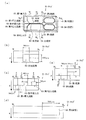
本発明に係る実施の一形態を、図面を参照しながら以下に説明する。図1は、後述する実施例1における粒子分別装置の概略の構成を示す(a)は側面図であり、(b)は(a)のX−X’線矢視断面図である。本実施の形態に係る粒子分別装置は、図1(a)に示すように、粒子分別装置の要部であるチップ1を備え、チップ1はその内部に、導入口2、分別流路3、分岐部4、第1流路5、第1排水口6、第2流路7および第2排水口8を少なくとも備えている。
[Embodiment 1]
An embodiment according to the present invention will be described below with reference to the drawings. 1A is a side view showing a schematic configuration of a particle sorting apparatus in Example 1 described later, and FIG. 1B is a cross-sectional view taken along line XX ′ in FIG. As shown in FIG. 1 (a), the particle sorting apparatus according to the present embodiment includes a
チップ1は、例えば、金属や樹脂にて形成することができる。用いることができる金属や樹脂としては、分別すべき粒子が吸着したり、分別液により溶解や変質したりしない限り、特に限定されない。樹脂は透明であってもよく、不透明であってもよい。樹脂の具体例としては、例えば、ポリジメチルシロキサン(PDMS)等を挙げることができる。チップ1の形状としては、図1(a)に示すように直方体形状である以外に、円板形状、三角柱形状、平行四辺形を底面とする四角柱形状、不定形状等、どのような形状であってもよい。
The
導入口2は、分別流路3内に粒子群を含む分別液を導入する導入口である。導入口2の大きさや形状は、分別流路3の大きさや形状に従って定めればよい。例えば、導入口2の形状は、外部から粒子群を含む分別液を導入するための送液管等を固定することができる形状であってもよい。また、粒子群を一点から分別流路3内に放出することができるように、導入口2を分別流路3の大きさに比べて細い構造としてもよく、または絞りを設けてもよい。 The introduction port 2 is an introduction port for introducing a separation liquid containing a particle group into the separation flow path 3. The size and shape of the introduction port 2 may be determined according to the size and shape of the separation channel 3. For example, the shape of the introduction port 2 may be a shape capable of fixing a liquid feeding pipe or the like for introducing a separation liquid containing a particle group from the outside. Further, the inlet 2 may have a structure that is narrower than the size of the separation channel 3 or may be provided with a throttle so that the particle group can be discharged into the separation channel 3 from a single point.
分別流路3は、分別液に含まれる粒子群を、下記式(1)(ストークスの式)に従って、粒子径および分別液との密度の差に基づいて分別する流路である。分別液中の粒子群は、分別流路3を一定方向に流れながらストークスの式である下記式(1)に従い、一定の速度で、重力方向に沈降、または、重力に逆らう方向に浮上する。また、理論上、粒子の密度と分別液の密度とが等しいとき、粒子は浮上も沈降もしない。 The separation flow path 3 is a flow path for separating a particle group contained in the separation liquid based on a difference in particle diameter and density from the separation liquid according to the following formula (1) (Stokes' formula). The particle group in the separation liquid flows in the separation flow path 3 in a fixed direction, and settles in the gravity direction or floats in a direction against the gravity at a constant speed according to the following equation (1) that is Stokes' expression. Theoretically, when the density of the particles and the density of the fractionation liquid are equal, the particles do not float or settle.
![]()
![]()
(但し、式(1)において、vsは粒子の分岐部4における理論上の浮上速度または沈降速度、Dpは粒子の粒子径、ρpは粒子の密度、ρfは分別液の密度、gは重力加速度、ηは分別液の粘度を表す。)
図8に従って、式(1)について理論的に説明する。図8に示された粒子a、粒子b、粒子cおよび粒子dの各密度は、粒子dが一番高く、粒子c、粒子b、粒子aの順に低いと仮定する。さらに、粒子cの密度は分別液と等しいと仮定する。この場合、密度が一番低い(最小密度の)粒子aの浮上速度が一番大きいので浮上する。また、密度が二番目に低い粒子bは、粒子aに比べて浮上速度が小さいものの浮上する。また、分別液と密度が等しい粒子cは、浮上も沈降もしない。さらに、密度が一番高い(最大密度の)粒子dは、沈降する。
(Where, in equation (1), v s is the theoretical ascent or sedimentation velocity at the particle branching section 4, Dp is the particle diameter of the particle, ρ p is the density of the particle, ρ f is the density of the fractionated liquid, g Is the gravitational acceleration, and η is the viscosity of the fraction.
Equation (1) will be theoretically described with reference to FIG. It is assumed that the density of the particles a, particles b, particles c, and particles d shown in FIG. 8 is the highest for the particles d and is lower in the order of the particles c, the particles b, and the particles a. Furthermore, it is assumed that the density of the particles c is equal to the fractionated liquid. In this case, the particle a having the lowest density (minimum density) floats because the flying speed is the highest. Further, the particle b having the second lowest density floats although the flying speed is lower than that of the particle a. Further, the particles c having the same density as the fractionated liquid do not float or settle. Further, the particles d having the highest density (maximum density) settle.
結果として、図8に示すように、分別流路3内では流れに従って、粒子a〜dは沈降または浮上する。つまり、粒子a〜dは、理論上、直線の流形を描きながら浮上または沈降する。そして、粒子aが重力に逆らう方向に浮上した距離a’は、粒子bが浮上した距離b’に比べ大きくなる。また、粒子dは、重力方向に距離d’だけ沈降する。 As a result, as shown in FIG. 8, the particles a to d settle or float according to the flow in the separation channel 3. That is, the particles a to d float or sink theoretically while drawing a straight flow shape. The distance a 'where the particles a have floated in the direction against gravity is larger than the distance b' where the particles b have floated. Further, the particle d settles by a distance d ′ in the direction of gravity.
すなわち、チップ1においては、上記式(1)に従って、分別する粒子群の粒子径や密度に応じて、分別流路3の長さや流路径、分別液の密度や粘度、流速等を最適な値に設定すればよい。
That is, in the
例えば、分別流路3が重力に対して水平であり、分別液との密度差がそれぞれ0.002g/mLである密度が低い粒子と密度が高い粒子とからなる粒子群がある場合には、分別流路3内の分別液の線速を7cm/分、分別液の流速を20μL/分、分別液の粘度を0.0018kg/(m・s)、粒子の粒子径を150μm、滞留時間を30秒とすると、粒子群は重力方向(または重力に逆らう方向)に450μm浮上または沈降する。これに従えば、粒子群が分別流路3内に無秩序に導入された場合、分別流路3の重力方向の流路径を450μm以下にすれば、全ての粒子が浮上または沈降し得る。また、粒子群が分別流路3内の一点に導入された場合、その一点から重力方向(または重力に逆らう方向)に向かって450μm付近に粒子群が浮上または沈降することがわかる。 For example, when the separation flow path 3 is horizontal with respect to gravity, and there is a particle group composed of particles with low density and particles with high density, each having a density difference of 0.002 g / mL from the separation liquid, The linear velocity of the separation liquid in the separation flow path 3 is 7 cm / min, the flow rate of the separation liquid is 20 μL / min, the viscosity of the separation liquid is 0.0018 kg / (m · s), the particle diameter of the particles is 150 μm, and the residence time is Assuming 30 seconds, the particle group floats or sinks 450 μm in the direction of gravity (or the direction against gravity). According to this, when the particle group is randomly introduced into the separation flow path 3, if the flow diameter in the gravity direction of the separation flow path 3 is set to 450 μm or less, all the particles can float or settle. In addition, when the particle group is introduced at one point in the separation flow path 3, it can be seen that the particle group floats or sinks in the vicinity of 450 μm from the one point toward the gravity direction (or the direction against gravity).
また、分別流路3は、ある程度の傾斜を有していても構わない。傾斜角は、分別液の流速や分別流路3の流路径等に従えばよい。分別流路3の傾斜角としては、具体的には、水平方向を0degとすると、−30〜30degの範囲内であることが好ましく、−15〜15degの範囲内であることがより好ましく、−5〜5degの範囲内であることがさらに好ましい。 Further, the separation channel 3 may have a certain degree of inclination. The inclination angle may be determined according to the flow rate of the separation liquid, the flow path diameter of the separation flow path 3, and the like. Specifically, the inclination angle of the separation flow path 3 is preferably in the range of −30 to 30 deg, more preferably in the range of −15 to 15 deg, where the horizontal direction is 0 deg. More preferably, it is in the range of 5 to 5 deg.
分別流路3の断面形状としては、図1(b)に示されるような長方形状に限定されずに、正方形状や円形状、楕円形状であってもよい。分別流路3の流路径(最小径)は、分別される粒子群の粒子径の3倍以上であることが好ましく、5倍以上であることがより好ましく、10倍以上であることがさらに好ましい。流路径は粒子径に対して大きいほどよく、粒子群が分別流路3内で詰まるおそれを、より低減することができる。但し、チップ1が過度に大きくならないように、分別流路3の流路径(最小径)は、分別される粒子群の粒子径の1,000倍以下であることが好ましい。同様に、分岐部4、第1流路5および第2流路7の流路径(最小径)は、分別される粒子群の粒子径の3倍以上であることが好ましく、5倍以上であることがより好ましく、10倍以上であることがさらに好ましい。
The cross-sectional shape of the separation channel 3 is not limited to the rectangular shape as shown in FIG. 1B, but may be a square shape, a circular shape, or an elliptical shape. The flow path diameter (minimum diameter) of the separation flow path 3 is preferably 3 times or more, more preferably 5 times or more, and even more preferably 10 times or more the particle diameter of the particle group to be sorted. . The flow path diameter is preferably as large as possible with respect to the particle diameter, and the possibility that the particle group is clogged in the separation flow path 3 can be further reduced. However, the flow path diameter (minimum diameter) of the separation flow path 3 is preferably 1,000 times or less the particle diameter of the particle group to be sorted so that the
また、分別流路3の流路径(最大径)は、具体的には、100,000μm以下であることが好ましく、10,000μm以下であることがより好ましく、1,000μm以下であることがさらに好ましい。流路径が大きすぎると、分別が困難になり、分別効率が低下するおそれがある。また、分別流路3の流路径(最小径)は、具体的には、1μm以上であることが好ましく、10μm以上であることがより好ましく、100μm以上であることがさらに好ましい。流路径が小さすぎると、粒子群が分別流路3内で詰まるおそれがある。 The flow path diameter (maximum diameter) of the separation flow path 3 is specifically preferably 100,000 μm or less, more preferably 10,000 μm or less, and further preferably 1,000 μm or less. preferable. If the flow path diameter is too large, the separation becomes difficult and the separation efficiency may be reduced. The flow path diameter (minimum diameter) of the separation flow path 3 is specifically preferably 1 μm or more, more preferably 10 μm or more, and further preferably 100 μm or more. If the channel diameter is too small, the particle group may be clogged in the separation channel 3.
また、分別流路3の長さは、分別すべき粒子群に従って設定すればよいものの、具体的には、0.1〜100cmであることが好ましく、1〜10cmであることがより好ましい。分別流路3が短すぎる場合には、分別の精度が低下し、コンタミネーションの原因となるおそれがある。また、分別流路3が長すぎる場合には、分別の効率が低下する。 Moreover, although the length of the separation channel 3 may be set according to the particle group to be separated, specifically, it is preferably 0.1 to 100 cm, and more preferably 1 to 10 cm. If the separation flow path 3 is too short, the separation accuracy is lowered, which may cause contamination. Moreover, when the separation flow path 3 is too long, the efficiency of the separation is lowered.
分岐部4は、分別流路3に接続され、分別流路3の少なくとも末端で式(1)に従って重力方向に分布した粒子群を含む分別液を、上方向(重力に逆らう方向)に向かって延びる第1流路5および下方向(重力方向)に向かって延びる第2流路7に分別する分岐点を備えている。分岐部4の構造は、例えば垂直Y字構造(図1の構造)であるが、この構成に限定されない。分岐部4の他の構造としては、例えば、垂直T字構造、二層構造、平面二層Y字構造(図3の構造)等が挙げられる。垂直Y字構造は、分別流路3から垂直方向にY字状に枝分かれしている構造であり、分別する粒子群が沈降する粒子および浮上する粒子の混合物である場合に、効率的に分別することができる構造である。本実施の形態に係る粒子分別装置を使用する場合には、チップ1の最大面を重力方向に対して凡そ垂直にして当該チップ1を固定すればよい。凡そ垂直とは、垂直を含むと共に、ある程度の傾斜角を有していてもよいという意味であり、チップ1の最大面を垂直にしたときを90degとした場合、当該傾斜角は60〜120degの範囲内であればよく、70〜110degの範囲内であることがより好ましい。当該傾斜角が小さすぎる場合、または大きすぎる場合には、分別の精度が低下するおそれがある。
The branching section 4 is connected to the separation flow path 3, and at the end of the separation flow path 3, the separation liquid containing the particle group distributed in the gravity direction according to the formula (1) is directed upward (direction against gravity). A branching point is provided to separate the first flow path 5 extending and the second flow path 7 extending downward (gravity direction). The structure of the branch part 4 is, for example, a vertical Y-shaped structure (structure shown in FIG. 1), but is not limited to this structure. Examples of other structures of the branch part 4 include a vertical T-shaped structure, a two-layer structure, a planar two-layer Y-shaped structure (structure shown in FIG. 3), and the like. The vertical Y-shaped structure is a structure branched in a Y-shape in the vertical direction from the separation flow path 3, and efficiently separates when the particle group to be separated is a mixture of settled particles and floating particles. It is a structure that can. When the particle sorting apparatus according to the present embodiment is used, the
また、垂直T字構造は、分別流路3から垂直方向にT字状に枝分かれしている点以外は、垂直Y字構造と同様の構造である。二層構造はチップ1の最大面と並行に二層に分かれている構造であり、チップ1の最大面を重力に対して水平にしてチップ1を固定して使用することができる。平面二層Y字構造は、二層に分かれている第1流路5および第2流路7がチップ1の最大面と並行にY字状に分かれていく構造である以外は二層構造と同様の構造である。
The vertical T-shaped structure is the same structure as the vertical Y-shaped structure except that the vertical T-shaped structure branches in a T shape from the separation flow path 3 in the vertical direction. The two-layer structure is a structure that is divided into two layers in parallel with the maximum surface of the
第1流路5は、分岐部4の上方向(重力に逆らう方向)に向かって延びる流路である。分別流路3において、分別流路3から分岐部4の方向(一定方向)に流れる分別液中を密度が低い粒子(分別液の密度より密度が低い粒子)群が浮上して上方向に分布しているため、分岐部4にて、密度が低い粒子群を含む分別液は、上方向に向かって形成された第1流路5に供給される。すなわち、第1流路5には、分別液に含まれる密度が低い粒子群が供給される。 The first flow path 5 is a flow path extending in the upward direction (the direction against gravity) of the branching section 4. In the separation flow path 3, a group of particles having a low density (particles having a density lower than the density of the separation liquid) floats in the separation liquid flowing in the direction from the separation flow path 3 to the branching portion 4 (constant direction) and is distributed upward. Therefore, at the branching section 4, the fractionated liquid containing the particle group having a low density is supplied to the first flow path 5 formed upward. That is, the first flow path 5 is supplied with a particle group having a low density contained in the separation liquid.
第1流路5の流路の形状は、長方形状であってもよく、正方形状や円形状、楕円形状、不定形状であってもよい。また、第1流路5の流路径(最大径)は、具体的には、100,000μm以下であることが好ましく、10,000μm以下であることがより好ましく、1,000μm以下であることがさらに好ましい。また、第1流路5の流路径(最小径)は、具体的には、1μm以上であることが好ましく、10μm以上であることがより好ましく、100μm以上であることがさらに好ましい。流路径が小さすぎると、粒子群が第1流路5内で詰まるおそれがある。また、第1流路5の長さは特に限定されない。 The shape of the flow path of the first flow path 5 may be a rectangular shape, or may be a square shape, a circular shape, an elliptical shape, or an indefinite shape. In addition, the channel diameter (maximum diameter) of the first channel 5 is specifically preferably 100,000 μm or less, more preferably 10,000 μm or less, and preferably 1,000 μm or less. Further preferred. Further, the channel diameter (minimum diameter) of the first channel 5 is specifically preferably 1 μm or more, more preferably 10 μm or more, and further preferably 100 μm or more. If the channel diameter is too small, the particle group may be clogged in the first channel 5. Moreover, the length of the 1st flow path 5 is not specifically limited.
第1流路5の断面積は、特に限定されないが、分別液の滞留や逆流等を防ぐ目的から、後述する第2流路7の断面積との合計が、分別流路3の断面積の値以下であることが好ましい。 The cross-sectional area of the first flow path 5 is not particularly limited, but the total of the cross-sectional area of the second flow path 7 to be described later is the cross-sectional area of the separation flow path 3 for the purpose of preventing retention of the separation liquid, back flow, and the like. It is preferable that it is below the value.
第1排水口6は、チップ1で分別された密度の低い粒子群を含む分別液を排出する排水口である。第1排水口6の大きさや形状は、第1流路5の大きさや形状に従って定めればよい。例えば、第1排水口6の形状は、チップ1で分別された粒子群を含む分別液を回収するための送液管等を固定するための形状であってもよい。或いは、第1排水口6の形状は、チップ1で分別された粒子群を含む分別液を回収するための液溜りを構成する形状であってもよい。
The first drain port 6 is a drain port that discharges a separation liquid containing a low-density particle group that has been sorted by the
第2流路7は、分岐部4の下方向(重力方向)に向かって延びる流路である。分別流路3において、分別流路3から分岐部4の方向(一定方向)に流れる分別液中を密度が高い粒子(分別液の密度より密度が高い粒子)群が沈降して下方向に分布しているため、分岐部4にて、密度が高い粒子群を含む分別液は、下方向に向かって形成された第2流路7に供給される。すなわち、第2流路7には、分別液に含まれる密度が高い粒子群が供給される。 The second flow path 7 is a flow path that extends downward (in the direction of gravity) of the branching section 4. In the separation channel 3, a group of high-density particles (particles having a density higher than the density of the separation solution) settles and distributes downward in the separation liquid flowing in the direction from the separation channel 3 toward the branching portion 4 (a certain direction). For this reason, the separation liquid containing the high-density particle group is supplied to the second flow path 7 formed in the downward direction at the branch portion 4. That is, the second flow path 7 is supplied with a particle group having a high density contained in the separation liquid.
第2流路7の流路の形状や流路径(最小径)については、第1流路5の流路の形状や流路径(最小径)と同様にすればよい。但し、第1流路5および第2流路7は互いに異なった構成であってもよく、例えば粒子径に応じて、第1流路5の流路径(最小径)を小さく、第2流路7の流路径(最小径)を大きくした構造であってもよい。 The shape and flow path diameter (minimum diameter) of the second flow path 7 may be the same as the flow path shape and flow path diameter (minimum diameter) of the first flow path 5. However, the first channel 5 and the second channel 7 may have different configurations. For example, the first channel 5 has a smaller channel diameter (minimum diameter) depending on the particle size, and the second channel 7 may have a structure in which the flow path diameter (minimum diameter) is increased.
第2排水口8は、チップ1で分別された密度の高い粒子群を含む分別液を排出する排水口である。第2排水口8の大きさや形状は、第2流路7の大きさや形状に従って定めればよい。例えば、第2排水口8の形状は、チップ1で分別された粒子群を含む分別液を回収するための送液管等を固定するための形状であってもよい。或いは、第2排水口8の形状は、チップ1で分別された粒子群を含む分別液を回収するための液溜りを構成する形状であってもよい。
The second drainage port 8 is a drainage port for discharging a separation liquid containing a high-density particle group sorted by the
本発明に係る粒子分別装置の要部であるチップ1は、例えば、マイクロ流路(マイクロメートルオーダーの流路)である上記分別流路3、分岐部4、第1流路5および第2流路7を構成する溝が形成された第一部材、および、上記分別流路3、分岐部4、第1流路5および第2流路7を構成する溝が形成された第二部材を、上記溝で分別流路3、分岐部4、第1流路5および第2流路7が構成されるように重ね合わせることにより、より簡単に形成することができる。また、このようにチップ1を形成することにより、分別流路3、分岐部4、第1流路5および第2流路7をより簡単に清掃することができる。
The
また、本発明に係る粒子分別装置の要部であるチップ1は、例えば、マイクロ流路である上記分別流路3、分岐部4および第1流路5を構成する溝が形成された第一部材、および、上記分別流路3、分岐部4および第2流路7を構成する溝が形成された第二部材を、上記溝で分別流路3、分岐部4、第1流路5および第2流路7が構成されるように重ね合わせることにより、より簡単に形成することができる。また、このようにチップ1を形成することにより、分別流路3、分岐部4、第1流路5および第2流路7をより簡単に清掃することができる。さらに、上記の構成によれば、第1流路5および第2流路7を分別流路3から見て段違いに(二層構造に)形成することができる(図3の構造)ので、粒子分別装置のチップ1の上下方向における幅(高さ)をより狭くすることができる。
In addition, the
さらには、本発明に係る粒子分別装置の要部であるチップ1は、例えば、マイクロ流路である上記分別流路3、分岐部4、第1流路5および第2流路7を構成する溝が形成された第一部材、および、溝が形成されていない平滑な第二部材を、上記溝で分別流路3、分岐部4、第1流路5および第2流路7が構成されるように重ね合わせることにより、さらに簡単に形成することができる。また、このようにチップ1を形成することにより、分別流路3、分岐部4、第1流路5および第2流路7をさらに簡単に清掃することができる。
Furthermore, the
粒子分別装置の分別流路3に供給する分別液は、粒子群を分散または懸濁させることができる液であればよい。分別液は、具体的には、例えば、水や有機溶媒であればよく、分別すべき粒子が溶解や変質したり、分別流路3、分岐部4、第1流路5および第2流路7が形成されているチップ1を溶解や変質したりしない性質の液体である限り、特に限定されない。また、分別液は、上記式(1)に基づき、分散させる粒子群の密度や粒子径、分別流路3等の流路径や流路の長さ等に従って、適宜、密度や粘度を変化させればよい。分別液の密度や粘度を変化させる方法としては、粒子を変質させない例えば塩や糖類等の有機化合物を予め溶解させておく方法が挙げられる。
The separation liquid supplied to the separation flow path 3 of the particle separation apparatus may be any liquid that can disperse or suspend particles. Specifically, the separation liquid may be, for example, water or an organic solvent, and the particles to be separated are dissolved or altered, or the separation flow path 3, the branch portion 4, the first flow path 5, and the second flow path. There is no particular limitation as long as it is a liquid that does not dissolve or alter the
分別液は、分別流路3内、分岐部4内、第1流路5内および第2流路7内を層流で流れる。すなわち、分別液は、チップ1内を層流で流れる。これにより、粒子群は、上記式(1)に従った挙動を行うことになる。
The separation liquid flows in a laminar flow in the separation flow path 3, the branch portion 4, the first flow path 5, and the second flow path 7. That is, the fractionation liquid flows in the
本発明において分別対象となる粒子群は、分別液中において安定に存在することができる粒子群であればよく、例えば、生体粒子、樹脂粒子、金属粒子等の粒子群が挙げられる。生体粒子としては、例えば、卵子を含む体細胞、赤血球、血小板、細菌類、酵母細菌、細胞フラクション、脂質小球、たんぱく質ミセル、プランクトン、藻類等であって、殆ど生体運動を伴わない粒子が挙げられる。例えば、本発明によれば、密度が互いに異なる受精卵と未受精卵との分別を行うことができる。また、樹脂粒子としては、有機高分子や無機高分子からなる粒子群が挙げられる。金属粒子としては、粒子状の合金、砂鉄、砂金等が挙げられる。粒子の形状は、球形であることが好ましいものの、概略球形や楕円球形、不定形破砕形であってもよい。 In the present invention, the particle group to be classified may be a particle group that can stably exist in the separation liquid, and examples thereof include a particle group such as biological particles, resin particles, and metal particles. Examples of biological particles include somatic cells containing eggs, red blood cells, platelets, bacteria, yeast bacteria, cell fractions, lipid globules, protein micelles, plankton, algae, etc., and particles that are hardly accompanied by biological movement. It is done. For example, according to the present invention, it is possible to separate fertilized eggs and unfertilized eggs having different densities. Examples of the resin particles include a particle group made of an organic polymer or an inorganic polymer. Examples of the metal particles include particulate alloys, iron sand, and gold dust. The shape of the particles is preferably spherical, but may be roughly spherical, elliptical, or irregularly crushed.
粒子の粒子径は、0.1μm以上であればよく、1μm以上であることがより好ましく、10μm以上であることがさらに好ましい。粒子の粒子径が小さすぎる場合には、上記式(1)を満たさなくなる上、粒子の浮上または沈降の速度が極めて遅くなるため、分別流路3を極端に長くする必要があり、粒子分別装置が大型化する。また、第1排水口6または第2排水口8から回収される粒子のロスが大きくなる場合がある。 The particle diameter of the particles may be 0.1 μm or more, more preferably 1 μm or more, and further preferably 10 μm or more. When the particle diameter of the particles is too small, the above formula (1) is not satisfied, and the speed of particle floating or sedimentation becomes extremely slow. Therefore, it is necessary to make the separation flow path 3 extremely long. Increases in size. Further, the loss of particles recovered from the first drain port 6 or the second drain port 8 may increase.
また、粒子の粒子径は、5,000μm以下であればよく、1,000μm以下であることがより好ましく、100μm以下であることがさらに好ましい。粒子の粒子径が大きすぎる場合には、上記式(1)を満たさなくなる上、粒子の浮上または沈降の速度が極めて速くなるため、分別液の流速が遅い場合には、粒子群が分別流路3内で詰まるおそれがある。また、精度の高い分別を容易に行うことが難しくなる場合がある。 Further, the particle diameter of the particles may be 5,000 μm or less, more preferably 1,000 μm or less, and still more preferably 100 μm or less. When the particle diameter of the particles is too large, the above formula (1) is not satisfied, and the speed of particle floating or sedimentation is extremely high. Therefore, when the flow rate of the separation liquid is low, the particle group is separated into the separation flow path. 3 may clog. In addition, it may be difficult to easily perform highly accurate separation.
また、第1流路5および第2流路7のそれぞれに分別される粒子同士の最小密度差は、特に限定されないものの、0.001g/mL以上であればよく、0.002g/mL以上であることがより好ましく、0.005g/mL以上であることがさらに好ましく、0.01g/mL以上であることが特に好ましい。これにより、分別した粒子同士のコンタミネーションを防ぐことができ、より精度の高い分別が可能となる。 Further, the minimum density difference between the particles separated into the first flow path 5 and the second flow path 7 is not particularly limited, but may be 0.001 g / mL or more, and may be 0.002 g / mL or more. More preferably, it is more preferably 0.005 g / mL or more, and particularly preferably 0.01 g / mL or more. Thereby, the contamination of the classified particle | grains can be prevented and classification with higher precision is attained.
すなわち、本実施の形態に係る粒子分別装置は、上記構成により、分別した粒子同士のコンタミネーションを防ぐことができ、より精度の高い分別が可能となる。 In other words, the particle sorting apparatus according to the present embodiment can prevent contamination between sorted particles by the above configuration, and enables more accurate sorting.
粒子分別装置は、要部であるチップ1の他に、必要に応じて、分別液を供給するシリンジポンプ等の送液装置や、粒子群を含む分別液を攪拌するスターラーやボルテックスミクサ等の攪拌装置、シリコーン等からなる送液管、水槽、吸引装置等を備えていてもよい。つまり、粒子分別装置は、攪拌装置で粒子群を含む分別液を攪拌して懸濁させ、当該分別液を送液装置で送液管を介して導入口2からチップ1内の分別流路3に供給してもよい。或いは、重力差を用いて高い位置から、粒子群を含む分別液を、懸濁させながら送液管等を介して導入口2からチップ1内の分別流路3に供給してもよい。或いは、第1排水口6および第2排水口8から吸引装置で分別液を吸引することで、粒子群を含む分別液を分別流路3に供給してもよい。そして、第1排水口6または第2排水口8から排出される粒子群を含む分別液は、送液管等を介して水槽に回収してもよい。また、第1排水口6および第2排水口8から送液管を介して吸引装置で分別液を吸引して水槽に回収してもよい。
In addition to the
また、第1排水口6または第2排水口8から排出される粒子群を含む分別液から当該粒子群を取り出す方法としては、例えば、濾過する方法、沈殿させる方法等が挙げられる。 Moreover, as a method of taking out the said particle group from the fraction liquid containing the particle group discharged | emitted from the 1st drain port 6 or the 2nd drain port 8, the method of filtering, the method of making it precipitate, etc. are mentioned, for example.
従って、本発明は、上記粒子分別装置を用いた、粒子群を、密度が高い粒子群と、密度の低い粒子群に分別する粒子分別方法も提供する。 Therefore, the present invention also provides a particle sorting method that uses the above-described particle sorting apparatus to sort a particle group into a particle group having a high density and a particle group having a low density.
〔実施の形態2〕
本発明に係る実施の他の形態を、図面を参照しながら以下に説明する。図3は、後述する実施例2における粒子分別装置の概略の構成を示す(a)は平面図であり、(b)は(a)のY−Y’線矢視断面図であり、(c)は(a)のY”−Y'''線矢視断面図である。本実施の形態に係る粒子分別装置は、図3(a)に示すように、粒子分別装置の要部であるチップ11を備え、チップ11はその内部に、第1導入口12、第1導入流路21、第2導入口19、第2導入流路20、合流部22、分別流路13、分岐部14、第1流路15、第1排水口16、第2流路17および第2排水口18を少なくとも備えている。
[Embodiment 2]
Another embodiment according to the present invention will be described below with reference to the drawings. FIG. 3A is a plan view showing a schematic configuration of a particle sorting apparatus in Example 2 described later, and FIG. 3B is a cross-sectional view taken along line YY ′ in FIG. ) Is a cross-sectional view taken along line Y ″ -Y ′ ″ in FIG. 4A. The particle sorting apparatus according to the present embodiment is a main part of the particle sorting apparatus as shown in FIG. The chip 11 includes a first introduction port 12, a first introduction channel 21, a second introduction port 19, a second introduction channel 20, a junction 22, a separation channel 13, and a branching unit 14. The first flow path 15, the first drain port 16, the second flow path 17 and the second drain port 18 are provided at least.
なお、チップ11は実施の形態1におけるチップ1に、第1導入口12および第2導入口19は導入口2に、分別流路13は分別流路3に、第1流路15は第1流路5に、第1排水口16は第1排水口6に、第2流路17は第2流路7に、第2排水口18は第2流路8に対応する。従って、以下の説明において特に記載していない構成または形態は、上記実施の形態1の構成または形態と同様である。
The chip 11 is the same as the
第1導入口12および第2導入口19は、第1導入流路21内または第2導入流路20内に粒子群を含む分別液を導入する導入口である。第1導入口12および第2導入口19の大きさや形状は、第1導入流路21および第2導入流路20の大きさや形状に従って定めればよい。例えば、第1導入流路21および第2導入流路20の形状は、実施の形態1の導入口2と同様に、外部から粒子群を含む分別液を導入するための送液管等を固定することができる形状であってもよい。また、粒子群を一点から分別流路13内に放出することができるように、第1導入口12および第2導入口19を分別流路13の大きさに比べて細い構造としてもよく、または絞りを設けてもよい。 The first introduction port 12 and the second introduction port 19 are introduction ports for introducing a separation liquid containing a particle group into the first introduction channel 21 or the second introduction channel 20. The size and shape of the first introduction port 12 and the second introduction port 19 may be determined according to the size and shape of the first introduction channel 21 and the second introduction channel 20. For example, the shape of the first introduction flow channel 21 and the second introduction flow channel 20 is fixed to a liquid supply pipe or the like for introducing a separation liquid containing a particle group from the outside, like the introduction port 2 of the first embodiment. The shape which can be made may be sufficient. Further, the first inlet 12 and the second inlet 19 may have a structure that is narrower than the size of the separation channel 13 so that the particle group can be discharged into the separation channel 13 from one point, or An aperture may be provided.
第1導入口12および第2導入口19からは、それぞれ異なった粒子群を含む分別液を供給してもよい。また、一方から粒子群を含む分別液を供給し、他方から緩衝液や異なる密度の別の分別液を供給してもよい。緩衝液は、粒子群を含む分別液の密度を一定に保つため、或いは、粒子を安定に保つために導入される。また、異なる密度の別の分別液を供給することにより、分別流路13内において粒子群を含む分別液の密度とは異なる特定の密度の分別液(混合液)を形成することができる。つまり、上記式(1)に従って粒子を分別するのに好適な密度の分別液に調節することができる。 From the 1st inlet 12 and the 2nd inlet 19, you may supply the fractionation liquid containing a different particle group, respectively. Alternatively, a fractionation liquid containing a particle group may be supplied from one side, and a buffer solution or another fractionation liquid having a different density may be supplied from the other side. The buffer solution is introduced in order to keep the density of the separation liquid containing the particle group constant or to keep the particles stable. Further, by supplying another separation liquid having a different density, a separation liquid (mixed liquid) having a specific density different from the density of the separation liquid including the particle group can be formed in the separation flow path 13. That is, it can be adjusted to a fractionation liquid having a density suitable for fractionating particles according to the above formula (1).
第1導入流路21および第2導入流路20は、それぞれ、第1導入口12および第2導入口19から合流部22へ粒子群を含む分別液を送液するための管である。第1導入流路21および第2導入流路20の流路径(最大径)は、分別流路13の流路径(最大径)と同一にすればよく、具体的には、50,000μm以下であることが好ましく、5,000μm以下であることがより好ましく、500μm以下であることがさらに好ましい。また、第1導入口12および第2導入口19の流路径(最小径)は、具体的には、1μm以上であることが好ましく、10μm以上であることがより好ましく、100μm以上であることがさらに好ましい。 The first introduction flow channel 21 and the second introduction flow channel 20 are pipes for feeding a separation liquid containing a particle group from the first introduction port 12 and the second introduction port 19 to the junction 22, respectively. The flow path diameter (maximum diameter) of the first introduction flow path 21 and the second introduction flow path 20 may be the same as the flow path diameter (maximum diameter) of the separation flow path 13, specifically, 50,000 μm or less. Preferably, it is 5,000 μm or less, and more preferably 500 μm or less. Further, the flow path diameters (minimum diameters) of the first introduction port 12 and the second introduction port 19 are specifically preferably 1 μm or more, more preferably 10 μm or more, and preferably 100 μm or more. Further preferred.
流路径(最小径)が小さすぎると、粒子群が第1導入流路21内および第2導入流路20内で詰まるおそれがある。第1導入流路21および第2導入流路20のそれぞれの流路径は、互いに異なっていてもよい。また、特に限定されないが、分別液の滞留や逆流等を防ぐ目的から、第1導入流路21と第2導入流路20との断面積との合計は、分別流路13の断面積の値以下であることが好ましい。 If the channel diameter (minimum diameter) is too small, the particle group may be clogged in the first introduction channel 21 and the second introduction channel 20. The diameters of the first introduction channel 21 and the second introduction channel 20 may be different from each other. In addition, although not particularly limited, for the purpose of preventing the retention or backflow of the separation liquid, the sum of the cross-sectional areas of the first introduction flow path 21 and the second introduction flow path 20 is the value of the cross-sectional area of the separation flow path 13. The following is preferable.
合流部22は、第1導入流路21と第2導入流路20とが合流する合流点を備えている。合流部22の構造は、実施の形態1の分岐部4と同様な構造であればよく、例えば平面Y字構造(図1の分岐部4の構造)、平面T字構造、二層構造、平面二層Y字構造(図3の構造)等が挙げられる。合流部22では、第1導入流路21および第2導入流路20の両方から流れてきた分別液や緩衝液を効率的に混合するために、その一部を徐々に細くした後、徐々に太くした構造としてもよい。または絞り構造を設けてもよい。 The merging portion 22 includes a merging point where the first introduction channel 21 and the second introduction channel 20 merge. The structure of the merging portion 22 may be the same as that of the branching portion 4 of the first embodiment. For example, a planar Y-shaped structure (structure of the branched portion 4 in FIG. 1), a planar T-shaped structure, a two-layer structure, a planar surface A two-layer Y-shaped structure (structure of FIG. 3) etc. are mentioned. In the merging section 22, in order to efficiently mix the fractionation liquid and the buffer solution flowing from both the first introduction flow path 21 and the second introduction flow path 20, a part thereof is gradually thinned, and then gradually It may be a thick structure. Alternatively, a diaphragm structure may be provided.
分別流路13は、実施の形態1の分別流路3と同様に、分別液に含まれる粒子群が上記式(1)に従って、粒子径および分別液との密度の差に基づき分別される流路である。したがって、チップ11は、上記式(1)に従って、分別する粒子群の粒子径や密度に応じて、分別流路13の長さや流路径、分別液の密度や粘度、流速等を最適な値に設定すればよい。 Similar to the separation flow path 3 of the first embodiment, the separation flow path 13 is a flow in which the particle group contained in the separation liquid is separated based on the difference between the particle diameter and the density of the separation liquid according to the above formula (1). Road. Therefore, according to the above formula (1), the chip 11 optimizes the length and flow path diameter of the sorting channel 13, the density and viscosity of the sorting solution, the flow rate, and the like according to the particle size and density of the particle group to be sorted. You only have to set it.
分岐部14は、図3において、平面二層Y字構造として形成されているが、実施の形態1の分岐部4と同様、これに限定されるものではない。 Although the branch part 14 is formed as a planar two-layer Y-shaped structure in FIG. 3, the branch part 14 is not limited to this as in the case of the branch part 4 of the first embodiment.
本実施の形態に係る粒子分別装置は、上記構成により、分別した粒子同士のコンタミネーションを防ぐことができ、より精度の高い分別が可能となる。 With the above configuration, the particle sorting apparatus according to the present embodiment can prevent contamination between sorted particles, and enables more accurate sorting.
〔実施の形態3〕
本発明に係る実施の他の形態を、図面を参照しながら以下に説明する。図6は、後述する実施例3における粒子分別装置の概略の構成を示す(a)は平面図であり、(b)は(a)のZ−Z’線矢視断面図であり、(c)は(a)のZ”−Z'''線矢視断面図である。本実施の形態に係る粒子分別装置は、図6(a)に示すように、粒子分別装置の要部であるチップ31を備え、チップ31はその内部に、第1導入口32、第1導入流路41、第2導入口39、第2導入流路40、粒子挿入部43、合流部42、分別流路33、分岐部34、第1流路35、第1排水口36、第2流路37および第2排水口38を少なくとも備えている。
[Embodiment 3]
Another embodiment according to the present invention will be described below with reference to the drawings. FIG. 6A is a plan view showing a schematic configuration of a particle sorting apparatus in Example 3 to be described later, and FIG. 6B is a cross-sectional view taken along line ZZ ′ in FIG. ) Is a cross-sectional view taken along the line Z ″ -Z ′ ″ in (a). The particle sorting apparatus according to the present embodiment is a main part of the particle sorting apparatus as shown in FIG. The chip 31 includes a first introduction port 32, a first introduction channel 41, a second introduction port 39, a second introduction channel 40, a particle insertion unit 43, a junction unit 42, and a separation channel. 33, the branch part 34, the 1st flow path 35, the 1st drain port 36, the 2nd flow path 37, and the 2nd drain port 38 are provided at least.
なお、チップ31は実施の形態2におけるチップ11に、第1導入口32は第1導入口12に、第2導入口39は第2導入口19に、合流部42は合流部22に、分別流路33は分別流路13に、分岐部34は分岐部14に、第1流路35は第1流路15に、第1排水口36は第1排水口16に、第2流路37は第2流路17に、第2排水口38は第2排水口18に対応する。従って、以下の説明において特に記載していない構成または形態は、上記実施の形態2の構成または形態と同様である。 The tip 31 is separated into the chip 11 in the second embodiment, the first introduction port 32 is separated into the first introduction port 12, the second introduction port 39 is separated into the second introduction port 19, and the junction portion 42 is separated into the junction portion 22. The flow path 33 is the separation flow path 13, the branch portion 34 is the branch section 14, the first flow path 35 is the first flow path 15, the first drain port 36 is the first drain port 16, and the second flow path 37. Corresponds to the second flow path 17, and the second drain port 38 corresponds to the second drain port 18. Therefore, the configuration or form not particularly described in the following description is the same as the configuration or form of the second embodiment.
第1導入流路41および第2導入流路40は、合流部42を介して分別流路33に向かって滑らかな曲線を描くようにして(ある曲率を有する曲線状に)接続されている。これにより、分別液または粒子群を含む分別液が円滑に流れるため、粒子群が詰まるおそれを、より低減することができる。また、粒子群を分別液中に効率的に分散することができるため、粒子分別装置の分別精度がより向上する。 The first introduction flow channel 41 and the second introduction flow channel 40 are connected so as to draw a smooth curve (in a curved shape having a certain curvature) toward the separation flow channel 33 via the merging portion 42. Thereby, since the classification liquid or the classification liquid containing particle groups flows smoothly, the possibility that the particle groups may be clogged can be further reduced. Moreover, since the particle group can be efficiently dispersed in the separation liquid, the separation accuracy of the particle separation device is further improved.
粒子挿入部43は、粒子群を懸濁液として、または、粒子群のみを挿入して合流部22にて分別液と混合、分散して、分別流路33に供給するための挿入口である。粒子群の挿入方法としては、当該粒子群を挿入することができる限り、特に限定されないが、例えば、シリンジポンプ等の送液装置を使用し、送液装置から管を介して粒子群を懸濁液として挿入する方法、分別液が粒子挿入部43から逆流しないように、重力差を用いて高い位置から粒子群を直接挿入する方法等が挙げられる。粒子挿入部43から直接挿入可能な粒子群としては、ゲル状の粒子群や弾力を有する粒子群が挙げられる。粒子挿入部43を介して粒子群を挿入することにより、粒子群を分別液中に効率的に分散させることができ、粒子群をより効率的に分別することができる。 The particle insertion portion 43 is an insertion port for supplying the particle group as a suspension or supplying only the particle group to the separation channel 33 by mixing and dispersing with the separation liquid in the merging portion 22. . The method for inserting the particle group is not particularly limited as long as the particle group can be inserted. For example, a liquid feeding device such as a syringe pump is used, and the particle group is suspended from the liquid feeding device via a tube. Examples thereof include a method of inserting as a liquid, a method of directly inserting a particle group from a high position using a difference in gravity so that the separation liquid does not flow backward from the particle insertion portion 43, and the like. Examples of the particle group that can be directly inserted from the particle insertion portion 43 include gel-like particle groups and elastic particle groups. By inserting the particle group through the particle insertion portion 43, the particle group can be efficiently dispersed in the separation liquid, and the particle group can be more efficiently separated.
第1流路35および第2流路37は、第1導入流路41および第2導入流路40と同様に、分岐部34を介して分別流路33に向かって滑らかな曲線を描くようにして(ある曲率を有する曲線状に)接続されている。これにより、分別液または粒子群を含む分別液が円滑に流れるため、粒子群が詰まるおそれを、より低減することができる。 Similarly to the first introduction channel 41 and the second introduction channel 40, the first channel 35 and the second channel 37 draw a smooth curve toward the separation channel 33 via the branch portion 34. Connected (in a curved line having a certain curvature). Thereby, since the classification liquid or the classification liquid containing particle groups flows smoothly, the possibility that the particle groups may be clogged can be further reduced.
〔実施の形態4〕
上記実施の形態1〜3で示される粒子分別装置の構成は、図9に示す構成であってもよい。図9は、粒子分別装置の分別流路および分岐部の変形例を示すものであり、概略の構成を説明する説明図である。具体的には、図9(a)は、分別液の密度よりも低い密度の粒子群同士を分別する構成を示した説明図であり、図9(b)は、分別液の密度に比べて極めて低い密度の粒子群だけを先に分別する構成を示した説明図であり、図9(c)は、分別液の密度よりも低い密度の粒子群、高い密度の粒子群に加え、分別液の密度に近い密度の粒子群を分別する構成を示した説明図である。以下、より具体的に説明する。
[Embodiment 4]
The structure shown in FIG. 9 may be sufficient as the structure of the particle | grain classification apparatus shown by the said Embodiment 1-3. FIG. 9 shows a modified example of the sorting flow path and the branching section of the particle sorting apparatus, and is an explanatory diagram for explaining a schematic configuration. Specifically, FIG. 9A is an explanatory diagram showing a configuration for separating particle groups having a density lower than the density of the separation liquid, and FIG. 9B is compared with the density of the separation liquid. FIG. 9C is an explanatory diagram showing a configuration in which only a very low density particle group is separated first, and FIG. 9C shows a separation liquid in addition to a particle group having a density lower than the density of the separation liquid and a high density particle group. It is explanatory drawing which showed the structure which sorts the particle group of the density close | similar to the density of this. More specific description will be given below.
図9(a)に示される構造においては、導入口(または分岐部)の流路径が分別流路の流路径に比べて狭い構造となっており、密度が互いに異なる二種類の粒子群が、下方向(重力方向)の一領域から第1流路201および第2流路202に供給される。分別液の密度よりも低い密度であって、密度が互いに異なる二種類の粒子群は、上記式(1)に従って、それぞれの浮上速度で浮上する。一定の条件において、式(1)に従えば、密度が互いに異なる二種類の粒子群は、分別流路の末端である分岐部において、それぞれ異なった高さ(重力方向に対する高さ)に位置する。すなわち、分岐部において上方向(重力に逆らう方向)に集まる粒子群と、分岐部において下方向(重力方向)に集まる粒子群とに別れることになり、それぞれ、第1流路201および第2流路202によって分別が可能となる。 In the structure shown in FIG. 9 (a), the flow path diameter of the introduction port (or branch part) is narrower than the flow path diameter of the separation flow path, and two types of particle groups having different densities are The first flow path 201 and the second flow path 202 are supplied from a region in the downward direction (gravity direction). Two types of particle groups having a density lower than the density of the separation liquid and different from each other float according to the above formula (1). Under certain conditions, according to the formula (1), two types of particle groups having different densities are located at different heights (heights relative to the direction of gravity) at the branch portions that are the ends of the separation flow paths. . That is, a particle group that collects in the upward direction (direction against gravity) at the branching part and a particle group that collects in the downward direction (gravity direction) at the branching part are divided into the first flow path 201 and the second flow, respectively. Sorting is possible by the path 202.
図9(b)に示される構造においては、導入口(または分岐部)の流路径が分別流路の流路径に比べて狭い構造となっており、密度が互いに異なる少なくとも二種類の粒子群が、中央の一領域から第2流路202に供給される。密度が互いに異なる少なくとも二種類の粒子群のうち、分別液の密度に比べて極めて低い密度の粒子群は、上方向(重力に逆らう方向)に比較的速い浮上速度で浮上する。従って、導入口(または分岐部)から一定の距離における位置を分岐点として、上方向(重力に逆らう方向)に第1流路201を設けることにより、一定の条件において、極めて低い密度の粒子群のみが第1流路201に供給されることによって分別が可能となる。また、残りの粒子群は、第2流路202に供給されることによって分別が可能となり、必要に応じて第2流路202に分岐部を設けることにより、さらに分別が可能となる。 In the structure shown in FIG. 9B, the flow path diameter of the introduction port (or branching portion) is narrower than the flow path diameter of the separation flow path, and there are at least two types of particle groups having different densities. The second flow path 202 is supplied from a central region. Of the at least two types of particle groups having different densities, the particle group having a very low density compared to the density of the fractionated liquid rises at a relatively high ascent rate in the upward direction (the direction against gravity). Therefore, by providing the first flow channel 201 in the upward direction (direction against gravity) with the position at a certain distance from the inlet (or branching portion) as a branching point, a particle group having a very low density under a certain condition. Separation becomes possible when only the first flow path 201 is supplied. Further, the remaining particle groups can be separated by being supplied to the second flow path 202, and can be further separated by providing a branch portion in the second flow path 202 as necessary.
図9(c)に示される構造においては、導入口(または分岐部)の流路径が分別流路の流路径に比べて狭い構造となっており、分別液の密度よりも低い密度の粒子群、高い密度の粒子群、および、分別液の密度に近い密度の粒子群の混合物からなる粒子群が、中央の一領域から第1流路301、第2流路302および第3流路303に供給される。混合物からなる上記粒子群のうち、分別液の密度よりも低い密度の粒子群は、上方向(重力に逆らう方向)に浮上する。また、分別液の密度よりも高い密度の粒子群は、下方向(重力方向)に沈降する。そして、分別液の密度に近い密度の粒子群は、上記式(1)に従えば、浮上も沈降もしないで、流路内を一定の高さを維持しながら流れる。従って、分別液の密度よりも低い密度の粒子群は上方向(重力に逆らう方向)に設けられた第1流路301に供給され、分別液の密度よりも高い密度の粒子群は下方向(重力方向)に設けられた第2流路302に供給され、分別液の密度に近い密度の粒子群は第1流路301と第2流路302との間(中央付近)に設けられた第3流路303に供給される。これにより、それぞれの粒子群は、第1流路301、第2流路302および第3流路303によって分別が可能となる。 In the structure shown in FIG. 9C, the diameter of the inlet (or branch) channel is narrower than that of the separation channel, and the particle group has a density lower than the density of the separation liquid. , A high-density particle group and a particle group composed of a mixture of particle groups with a density close to the density of the separation liquid are supplied from the central region to the first flow path 301, the second flow path 302, and the third flow path 303. Supplied. Among the above particle group made of a mixture, a particle group having a density lower than the density of the fractionation liquid floats upward (a direction against gravity). Moreover, the particle group with a density higher than the density of the fractionated liquid settles downward (in the direction of gravity). And according to said Formula (1), the particle group of the density close | similar to the density of a classification | fractionation liquid flows, maintaining a fixed height in a flow path, without floating and settling. Therefore, the particle group having a density lower than the density of the separation liquid is supplied to the first flow path 301 provided in the upward direction (the direction against gravity), and the particle group having a density higher than the density of the separation liquid is directed downward ( The particle group having a density close to the density of the separation liquid is supplied to the second flow path 302 provided in the direction of gravity), and the particle group is provided between the first flow path 301 and the second flow path 302 (near the center). It is supplied to the three flow paths 303. Thereby, each particle group can be separated by the first flow path 301, the second flow path 302, and the third flow path 303.
〔実施の形態5〕
本発明に係る実施のさらに他の形態を、図面を参照しながら以下に説明する。図10は、後述する実施例6における粒子分別装置の概略の構成を示す(a)は平面図であり、(b)は(a)のW1−W2線矢視断面図であり、(c)は(a)のW3−W4線矢視断面図であり、(d)は(a)のW5−W6線矢視断面図である。本実施の形態に係る粒子分別装置は、図10(a)に示すように、粒子分別装置の要部であるチップ51を備え、チップ51はその内部に、第1導入口52、第1導入流路61、第2導入口59、第2導入流路60、粒子挿入部63、合流部62、分別流路53、分岐部54、第1流路55、第1液溜り56、第2流路57および第2液溜り58を少なくとも備えている。
[Embodiment 5]
Still another embodiment of the present invention will be described below with reference to the drawings. FIG. 10A is a plan view showing a schematic configuration of a particle sorting apparatus in Example 6 described later, and FIG. 10B is a cross-sectional view taken along line W 1 -W 2 in FIG. c) is a cross-sectional view taken along line W 3 -W 4 of (a), and (d) is a cross-sectional view taken along line W 5 -W 6 of (a). As shown in FIG. 10A, the particle sorting apparatus according to the present embodiment includes a chip 51 which is a main part of the particle sorting apparatus, and the chip 51 includes a first introduction port 52 and a first introduction therein. The channel 61, the second inlet 59, the second inlet channel 60, the particle insertion portion 63, the merging portion 62, the separation channel 53, the branching portion 54, the first channel 55, the first liquid reservoir 56, the second flow A passage 57 and a second liquid reservoir 58 are provided at least.
なお、チップ51は実施の形態3におけるチップ31に、第1導入口52は第1導入口32に、第2導入口59は第2導入口39に、第1導入流路61は第1導入流路41に、第2導入流路60は第2導入流路40に、合流部62は合流部42に、分別流路53は分別流路33に、分岐部54は分岐部34に、第1流路55は第1流路35に、第1液溜り56は第1排水口36に、第2流路57は第2流路37に、第2液溜り58は第2排水口38に対応する。従って、以下の説明において特に記載していない構成または形態は、上記実施の形態3の構成または形態と同様である。 In addition, the chip 51 is the chip 31 in the third embodiment, the first introduction port 52 is the first introduction port 32, the second introduction port 59 is the second introduction port 39, and the first introduction channel 61 is the first introduction port. In the channel 41, the second introduction channel 60 is in the second introduction channel 40, the junction 62 is in the junction 42, the separation channel 53 is in the separation channel 33, the branch 54 is in the branch 34, The first flow path 55 is connected to the first flow path 35, the first liquid reservoir 56 is connected to the first drain outlet 36, the second flow path 57 is connected to the second flow path 37, and the second liquid reservoir 58 is connected to the second drain outlet 38. Correspond. Therefore, the configuration or form not specifically described in the following description is the same as the configuration or form of the third embodiment.
第1液溜り56は、チップ51で分別された密度の低い粒子群を含む分別液を排出する排水口の代わりに設けられ、チップ51で分別された粒子群を含む分別液を回収するための液溜りを構成する形状となっている。第2液溜り58は、チップ51で分別された密度の高い粒子群を含む分別液を排出する排水口の代わりに設けられ、チップ51で分別された粒子群を含む分別液を回収するための液溜りを構成する形状となっている。 The first liquid reservoir 56 is provided in place of a drain outlet that discharges a separation liquid containing low-density particle groups separated by the chip 51, and collects a separation liquid containing the particle groups separated by the chip 51. The shape forms a liquid pool. The second liquid reservoir 58 is provided in place of a drain outlet that discharges a separation liquid containing a high-density particle group separated by the chip 51, and collects a separation liquid containing the particle group separated by the chip 51. The shape forms a liquid pool.
本実施の形態に係る粒子分別装置は、上記構成により、実施の形態3で示される粒子分別装置と同様に、分別した粒子同士のコンタミネーションを防ぐことができ、より精度の高い分別が可能となる。 The particle sorting apparatus according to the present embodiment can prevent contamination between the separated particles, as in the case of the particle sorting apparatus shown in the third embodiment, by the above configuration, and enables more accurate sorting. Become.
以下、本発明を、実施例を用いてさらに説明する。 Hereinafter, the present invention will be further described using examples.
〔実施例1〕
図1は、粒子分別装置の概略の構成を示す(a)は側面図であり、(b)は(a)のX−X’線矢視断面図である。本実施例に係る粒子分別装置は、実施の形態1に係る粒子分別装置の一具体例である。チップ1は、従来公知の製造方法で製造した。すなわち、精密機械を用いてポリメタクリル酸メチル(PMMA)樹脂を加工して、マイクロ流路となる矩形状の凸部を有する型を形成し、この型を鋳型として、ポリジメチルシロキサン(PDMS)樹脂を用いて、チップ1となる溝が形成された第一部材を製造すると共に、溝が形成されていない平滑な第二部材(ガラス基板)を製造し、両部材を重ね合わせてチップ1を製造した。
[Example 1]
FIG. 1A is a side view showing a schematic configuration of a particle sorting apparatus, and FIG. 1B is a cross-sectional view taken along line XX ′ in FIG. The particle sorting apparatus according to this example is a specific example of the particle sorting apparatus according to the first embodiment. The
分別流路3の断面は、垂直方向に600μm、水平方向に200μmの長方形となるように加工した。また、分別流路3の長さは、4cmとした。第1流路5および第2流路7の断面は、垂直方向に300μm、水平方向に200μmの長方形となるように加工した。また、分岐部4は、垂直Y字構造を形成するように加工した。さらに、ポリジメチルシロキサン樹脂からなるチップ1の強度を高めるために、当該チップ1の表面(最大面)に、補強のためのガラス基板を、従来公知の酸素プラズマ処理を用いることによって接合した。
The cross section of the separation channel 3 was processed so as to be a rectangle of 600 μm in the vertical direction and 200 μm in the horizontal direction. The length of the separation channel 3 was 4 cm. The cross section of the 1st flow path 5 and the 2nd flow path 7 was processed so that it might become a rectangle of 300 micrometers in a perpendicular direction, and 200 micrometers in a horizontal direction. Moreover, the branch part 4 was processed so as to form a vertical Y-shaped structure. Furthermore, in order to increase the strength of the
このようにして製造したチップ1を含む粒子分別装置の分別評価試験を行った。分別評価試験の方法を以下に具体的に説明する。チップ1は分別評価試験時に、その最大面が重力方向と垂直になるようにして固定した。すなわち、チップ1は垂直に固定して用いた。
The particle separation apparatus including the
分別評価試験に用いる分別液として、濃度1.2g/mLに調製したショ糖水溶液を用いた。分別評価試験に用いる粒子群として、一般的にゲル濾過に用いられるポリアクリルアミドゲルを用いた。当該ポリアクリルアミドゲルとして、低い密度を有するポリアクリルアミドゲルA、および、高い密度を有するポリアクリルアミドゲルBの二種類を用いた。ポリアクリルアミドゲルAは、ショ糖水溶液(濃度1.2g/mL)による膨潤時において、密度1.0g/mL以下、且つ、粒子径45〜90μmである。また、ポリアクリルアミドゲルBは、ショ糖水溶液(濃度1.2g/mL)による膨潤時において、密度1.3g/mL以上、且つ、粒子径45〜90μmである。 A sucrose aqueous solution prepared to a concentration of 1.2 g / mL was used as a separation solution used in the separation evaluation test. A polyacrylamide gel generally used for gel filtration was used as a particle group used in the classification evaluation test. As the polyacrylamide gel, two types of polyacrylamide gel A having a low density and polyacrylamide gel B having a high density were used. Polyacrylamide gel A has a density of 1.0 g / mL or less and a particle diameter of 45 to 90 μm when swollen with an aqueous sucrose solution (concentration: 1.2 g / mL). Polyacrylamide gel B has a density of 1.3 g / mL or more and a particle size of 45 to 90 μm when swollen with a sucrose aqueous solution (concentration 1.2 g / mL).
粒子群を含む分別液は、シリンジポンプを使用して、送液管を介して導入口2から分別流路3に送液した。粒子を含む分別液の流速は4.0μL/分とし、マイクロ流路内の流速は3.3cm/分とした。そして、第1流路5および第2流路7から排出される粒子群を含む分別液は、第1排水口6および第2排水口8から送液管を介して回収した。その後、分別液から粒子群を取り出した。 The fractionation liquid containing a particle group was sent to the separation flow path 3 from the inlet 2 via the liquid feed pipe using a syringe pump. The flow rate of the separation liquid containing particles was 4.0 μL / min, and the flow rate in the microchannel was 3.3 cm / min. And the fractionated liquid containing the particle group discharged | emitted from the 1st flow path 5 and the 2nd flow path 7 was collect | recovered through the liquid sending pipe | tube from the 1st drainage port 6 and the 2nd drainage port 8. FIG. Then, the particle group was taken out from the fractionated liquid.
分別評価試験の結果、ポリアクリルアミドゲルAは、分別流路3内を流れながら浮上し、分岐部4にて上方向に接続している第1流路5に供給された。ポリアクリルアミドゲルAにポリアクリルアミドゲルBは混入しておらず、第1排水口6からはポリアクリルアミドゲルAのみが回収された。一方、ポリアクリルアミドゲルBは、分別流路3内を流れながら沈降し、分岐部4にて下方向に接続している第2流路7に供給された。ポリアクリルアミドゲルBにポリアクリルアミドゲルAは混入しておらず、第2排水口8からはポリアクリルアミドゲルBのみが回収された。 As a result of the separation evaluation test, the polyacrylamide gel A floated while flowing in the separation flow path 3 and was supplied to the first flow path 5 connected upward at the branching section 4. Polyacrylamide gel B was not mixed in polyacrylamide gel A, and only polyacrylamide gel A was recovered from first drain port 6. On the other hand, the polyacrylamide gel B settled while flowing in the separation channel 3, and was supplied to the second channel 7 connected downward at the branching portion 4. Polyacrylamide gel A was not mixed in polyacrylamide gel B, and only polyacrylamide gel B was recovered from second drainage port 8.
図2は、(a),(b)共に、分別評価試験での粒子分別装置の分岐部4近傍を、水平方向から観察した側面図である。図2(a)では、ポリアクリルアミドゲルAが分別流路3内を流れながら浮上し、分岐部4にて上方向に接続している第1流路5に供給される様子が示されている。また、図2(b)では、ポリアクリルアミドゲルBが分別流路3内を流れながら沈降し、分岐部4にて下方向に接続している第2流路7に供給される様子が示されている。 FIGS. 2A and 2B are side views of the vicinity of the branching portion 4 of the particle sorting apparatus in the sorting evaluation test observed from the horizontal direction. FIG. 2A shows a state in which the polyacrylamide gel A floats while flowing in the separation flow path 3 and is supplied to the first flow path 5 connected upward at the branching portion 4. . Further, FIG. 2B shows a state in which the polyacrylamide gel B sinks while flowing in the separation flow path 3 and is supplied to the second flow path 7 connected downward at the branching portion 4. ing.
〔実施例2〕
図3は、粒子分別装置の概略の構成を示す(a)は平面図であり、(b)は(a)のY−Y’線矢視断面図であり、(c)は(a)のY”−Y'''線矢視断面図である。本実施例に係る粒子分別装置は、実施の形態2に係る粒子分別装置の一具体例である。チップ11は、実施例1のチップ1と同様にして、鋳型を用いて第一部材および第二部材を製造し、両部材を重ね合わせて製造した。
[Example 2]
3A is a plan view, FIG. 3B is a cross-sectional view taken along line YY ′ of FIG. 3A, and FIG. 3C is a cross-sectional view of FIG. It is a sectional view taken along line Y ″ -Y ′ ″. The particle sorting apparatus according to this example is a specific example of the particle sorting apparatus according to Embodiment 2. The chip 11 is the chip of Example 1. In the same manner as in No. 1, the first member and the second member were manufactured using a mold, and the two members were overlapped and manufactured.
分別流路13の断面は、垂直方向に400μm、水平方向に400μmの正方形となるように加工した。また、分別流路13の長さは、4cmとした。第1流路15および第2流路17の断面は、垂直方向に200μm、水平方向に400μmの長方形となるように加工した。また、合流部22および分岐部14は、平面二層Y字構造を形成するように加工した。すなわち、合流部22および分岐部14は垂直方向から見た形状がY字状であり、立体的には二つの流路が重なって「く」の字状となるように形成した。 The cross section of the separation channel 13 was processed so as to be a square of 400 μm in the vertical direction and 400 μm in the horizontal direction. The length of the separation channel 13 was 4 cm. The cross sections of the first flow path 15 and the second flow path 17 were processed so as to have a rectangular shape of 200 μm in the vertical direction and 400 μm in the horizontal direction. Moreover, the junction part 22 and the branch part 14 were processed so that a planar double layer Y-shaped structure might be formed. That is, the joining portion 22 and the branching portion 14 are Y-shaped when viewed from the vertical direction, and are formed so that the three flow paths overlap each other to form a “<” shape.
チップ11は分別評価試験時に、その最大面が水平方向と垂直になるようにして固定した。すなわち、チップ11は水平に固定して用いた。また、粒子を含む分別液の流速は4.0μL/分とし、マイクロ流路内の流速は2.5cm/分とした。さらに、第1導入口12および第2導入口19の両方から同一の速度で粒子群を含む分別液を導入した。それ以外の条件は、実施例1の条件と同じにした。 The chip 11 was fixed so that the maximum surface thereof was perpendicular to the horizontal direction during the separation evaluation test. That is, the chip 11 was used while being fixed horizontally. Further, the flow rate of the separation liquid containing particles was 4.0 μL / min, and the flow rate in the microchannel was 2.5 cm / min. Furthermore, a fractionation liquid containing particle groups was introduced at the same speed from both the first introduction port 12 and the second introduction port 19. The other conditions were the same as those in Example 1.
分別評価試験の結果、ポリアクリルアミドゲルAは、分別流路13内を流れながら浮上し、分岐部14にて上方向に接続している第1流路15に供給された。ポリアクリルアミドゲルAにポリアクリルアミドゲルBは混入しておらず、第1排水口16からはポリアクリルアミドゲルAのみが回収された。一方、ポリアクリルアミドゲルBは、分別流路13内を流れながら沈降し、分岐部14にて下方向に接続している第2流路17に供給された。ポリアクリルアミドゲルBにポリアクリルアミドゲルAは混入しておらず、第2排水口18からはポリアクリルアミドゲルBのみが回収された。 As a result of the separation evaluation test, the polyacrylamide gel A floated while flowing in the separation flow path 13 and was supplied to the first flow path 15 connected upward at the branching portion 14. Polyacrylamide gel B was not mixed in polyacrylamide gel A, and only polyacrylamide gel A was recovered from first drain port 16. On the other hand, the polyacrylamide gel B settled while flowing in the separation flow path 13 and was supplied to the second flow path 17 connected downward at the branching portion 14. Polyacrylamide gel A was not mixed into polyacrylamide gel B, and only polyacrylamide gel B was recovered from second drain port 18.
図4(a)および図5(a)は、分別評価試験での粒子分別装置の分岐部14近傍を、垂直方向から観察した平面図であり、図4(b)および図5(b)はそれぞれ(a)に対応する水平方向から見た概略の断面図である。図4(a),(b)では、ポリアクリルアミドゲルAが分別流路13内を流れながら浮上し、分岐部14にて上方向に接続している第1流路15に供給される様子が示されている。また、図5(a),(b)では、ポリアクリルアミドゲルBが分別流路13内を流れながら沈降し、分岐部14にて下方向に接続している第2流路17に供給される様子が示されている。 4 (a) and 5 (a) are plan views of the vicinity of the branching portion 14 of the particle sorting apparatus in the sorting evaluation test, as observed from the vertical direction. FIGS. 4 (b) and 5 (b) are views. It is the schematic sectional drawing seen from the horizontal direction corresponding to (a), respectively. 4A and 4B, the polyacrylamide gel A floats while flowing in the separation flow path 13 and is supplied to the first flow path 15 connected upward at the branching portion 14. It is shown. 5 (a) and 5 (b), the polyacrylamide gel B settles while flowing in the separation flow path 13, and is supplied to the second flow path 17 connected downward at the branching portion 14. The situation is shown.
〔実施例3〕
図6は、粒子分別装置の概略の構成を示す(a)は平面図であり、(b)は(a)のZ−Z’線矢視断面図であり、(c)は(a)のZ”−Z'''線矢視断面図である。本実施例に係る粒子分別装置は、実施の形態3に係る粒子分別装置の一具体例である。チップ31は、実施例2のチップ11と同様にして製造した。
Example 3
6A is a plan view, FIG. 6B is a cross-sectional view taken along the line ZZ ′ of FIG. 6A, and FIG. 6C is a cross-sectional view of FIG. Fig. 3 is a cross-sectional view taken along the line Z "-Z '". The particle sorting apparatus according to the present example is a specific example of the particle sorting apparatus according to Embodiment 3. The chip 31 is the chip of Example 2. 11 was produced in the same manner.
分別流路33の断面は、垂直方向に400μm、水平方向に700μmの長方形となるように加工した。また、分別流路33の長さは、4cmとした。第1導入流路41、第2導入流路40、第1流路35および第2流路37の断面は、垂直方向に200μm、水平方向に400μmの長方形となるように加工した。さらに、粒子挿入部43の断面は、垂直方向に200μmまたは300μm、水平方向に200μmまたは300μmの正方形となるように加工した。また、合流部42および分岐部34は、平面二層Y字構造を形成するように加工した。すなわち、合流部42および分岐部34は垂直方向から見た形状がY字状であり、立体的には二つの流路が重なって「く」の字状となるように形成した。第1導入流路41および第2導入流路40は、合流部42を介して分別流路33に向かって滑らかな曲線を描くようにして(ある曲率を有する曲線状に)形成した。第1流路35および第2流路37は、分岐部34を介して分別流路33に向かって滑らかな曲線を描くようにして(ある曲率を有する曲線状に)形成した。 The cross section of the separation channel 33 was processed so as to be a rectangle of 400 μm in the vertical direction and 700 μm in the horizontal direction. The length of the separation channel 33 was 4 cm. The cross sections of the first introduction flow channel 41, the second introduction flow channel 40, the first flow channel 35, and the second flow channel 37 were processed so as to have a rectangular shape of 200 μm in the vertical direction and 400 μm in the horizontal direction. Furthermore, the cross section of the particle insertion portion 43 was processed to be a square of 200 μm or 300 μm in the vertical direction and 200 μm or 300 μm in the horizontal direction. Moreover, the junction part 42 and the branch part 34 were processed so that a planar two-layer Y-shaped structure might be formed. In other words, the joining portion 42 and the branching portion 34 are Y-shaped when viewed from the vertical direction, and three-dimensionally, the two flow paths are overlapped to form a “<” shape. The first introduction flow channel 41 and the second introduction flow channel 40 were formed so as to draw a smooth curve (in a curved shape having a certain curvature) toward the separation flow channel 33 via the merging portion 42. The first flow path 35 and the second flow path 37 were formed so as to draw a smooth curve toward the separation flow path 33 via the branch portion 34 (in a curved shape having a certain curvature).
このようにして製造したチップ31を含む粒子分別装置の分別評価試験(二回)を行った。チップ31は分別評価試験時に、その最大面が水平方向と垂直になるようにして固定した。すなわち、チップ31は水平に固定して用いた。 A separation evaluation test (twice) of the particle sorting apparatus including the chip 31 thus manufactured was performed. The chip 31 was fixed so that the maximum surface thereof was perpendicular to the horizontal direction during the separation evaluation test. That is, the chip 31 was used while being fixed horizontally.
分別評価試験に用いる分別液として、濃度1.05g/mLに調製したショ糖水溶液を用いた。分別評価試験に用いる粒子群として、粒子径の標準として用いられるポリスチレン粒子を用いた。当該ポリスチレン粒子として、低い密度を有するポリスチレン粒子A、および、高い密度を有するポリスチレン粒子Bの二種類を用いた。ポリスチレン粒子Aは、ショ糖水溶液(濃度1.05g/mL)による膨潤時において、密度1.04〜1.05g/mL以下、且つ、粒子径150μmである。また、ポリスチレン粒子Bは、ショ糖水溶液(濃度1.05g/mL)による膨潤時において、密度1.05〜1.06g/mL以上、且つ、粒子径140μmである。 A sucrose aqueous solution prepared to a concentration of 1.05 g / mL was used as a separation solution used in the separation evaluation test. As the particle group used for the classification evaluation test, polystyrene particles used as a standard of particle diameter were used. As the polystyrene particles, two kinds of polystyrene particles A having a low density and polystyrene particles B having a high density were used. The polystyrene particles A have a density of 1.04 to 1.05 g / mL or less and a particle diameter of 150 μm when swollen with an aqueous sucrose solution (concentration: 1.05 g / mL). The polystyrene particles B have a density of 1.05 to 1.06 g / mL or more and a particle diameter of 140 μm when swollen with an aqueous sucrose solution (concentration: 1.05 g / mL).
分別液は、シリンジポンプを使用して、送液管を介して第1導入口32および第2導入口39から同一の流速で分別流路33に送液した。粒子群は、粒子挿入部43から挿入した。粒子を含む分別液の流速は20μL/分とし、マイクロ流路である分液流路33内の流速は7.1cm/分とした。そして、第1流路35および第2流路37から排出される粒子群を含む分別液は、第1排水口36および第2排水口38から送液管を介して回収した。その後、分別液から粒子群を取り出した。それ以外の条件は、実施例2の条件と同じにした。 The separation liquid was fed from the first introduction port 32 and the second introduction port 39 to the separation flow path 33 at the same flow rate via a liquid feed pipe using a syringe pump. The particle group was inserted from the particle insertion portion 43. The flow rate of the separation liquid containing particles was 20 μL / min, and the flow rate in the liquid separation channel 33, which is a microchannel, was 7.1 cm / min. And the fractionated liquid containing the particle group discharged | emitted from the 1st flow path 35 and the 2nd flow path 37 was collect | recovered via the liquid feeding pipe | tube from the 1st drainage port 36 and the 2nd drainage port 38. FIG. Then, the particle group was taken out from the fractionated liquid. The other conditions were the same as those in Example 2.
分別評価試験の結果、二回とも、ポリスチレン粒子Aは、分別流路33内を流れながら浮上し、分岐部34にて上方向に接続している第1流路35に供給された。ポリスチレン粒子Aにポリスチレン粒子Bは混入しておらず、第1排水口36からはポリスチレン粒子Aのみが回収された。一方、ポリスチレン粒子Bは、分別流路33内を流れながら沈降し、分岐部34にて下方向に接続している第2流路37に供給された。ポリスチレン粒子Bにポリスチレン粒子Aは混入しておらず、第2排水口38からはポリスチレン粒子Bのみが回収された。 As a result of the separation evaluation test, the polystyrene particles A floated while flowing in the separation flow path 33 and were supplied to the first flow path 35 connected in the upward direction at the branch portion 34. The polystyrene particles B were not mixed with the polystyrene particles A, and only the polystyrene particles A were recovered from the first drain port 36. On the other hand, the polystyrene particles B settled while flowing in the separation flow path 33, and were supplied to the second flow path 37 connected downward at the branch portion 34. The polystyrene particles B were not mixed with the polystyrene particles B, and only the polystyrene particles B were recovered from the second drain port 38.
図7(a)は、分別評価試験での粒子分別装置の分岐部34近傍を、垂直方向から観察した平面図であり、(b)は(a)に対応する水平方向から見た概略の断面図である。図7(a)では、ポリスチレン粒子Aが分別流路33内を流れながら浮上し、分岐部34にて上方向に接続している第1流路35に供給される様子が示されている。また、図7(b)では、ポリスチレン粒子Bが分別流路33内を流れながら沈降し、分岐部34にて下方向に接続している第2流路37に供給される様子が示されている。 FIG. 7A is a plan view of the vicinity of the branching portion 34 of the particle sorting apparatus in the sorting evaluation test observed from the vertical direction, and FIG. 7B is a schematic cross section seen from the horizontal direction corresponding to FIG. FIG. FIG. 7A shows a state in which the polystyrene particles A float while flowing in the separation flow path 33 and are supplied to the first flow path 35 connected upward at the branching portion 34. Further, FIG. 7B shows a state in which the polystyrene particles B settle while flowing in the separation flow path 33 and are supplied to the second flow path 37 connected downward at the branching portion 34. Yes.
〔実施例4〕
粒子挿入部43の断面を、垂直方向に300μm、水平方向に300μmの正方形となるように加工した以外は、実施例3と同様にしてチップ31を製造した。そして、実施例3と同様にして、チップ31を含む粒子分別装置の分別評価試験を行った。
Example 4
A chip 31 was manufactured in the same manner as in Example 3 except that the cross section of the particle insertion portion 43 was processed to be a square of 300 μm in the vertical direction and 300 μm in the horizontal direction. Then, in the same manner as in Example 3, a classification evaluation test of the particle sorting apparatus including the chip 31 was performed.
分別評価試験の結果、ポリスチレン粒子Aは、分別流路33内を流れながら浮上し、分岐部34にて上方向に接続している第1流路35に供給された。ポリスチレン粒子Aにポリスチレン粒子Bは混入しておらず、第1排水口36からはポリスチレン粒子Aのみが回収された。一方、ポリスチレン粒子Bは、分別流路33内を流れながら沈降し、分岐部34にて下方向に接続している第2流路37に供給された。ポリスチレン粒子Bにポリスチレン粒子Aは混入しておらず、第2排水口38からはポリスチレン粒子Bのみが回収された。 As a result of the separation evaluation test, the polystyrene particles A floated while flowing in the separation flow path 33 and were supplied to the first flow path 35 connected upward at the branching portion 34. The polystyrene particles B were not mixed with the polystyrene particles A, and only the polystyrene particles A were recovered from the first drain port 36. On the other hand, the polystyrene particles B settled while flowing in the separation flow path 33, and were supplied to the second flow path 37 connected downward at the branch portion 34. The polystyrene particles B were not mixed with the polystyrene particles B, and only the polystyrene particles B were recovered from the second drain port 38.
〔実施例5〕
粒子挿入部43の断面を、垂直方向に200μm、水平方向に200μmの正方形となるように加工した以外は、実施例3と同様にしてチップ31を製造した。そして、実施例3と同様にして、チップ31を含む粒子分別装置の分別評価試験を行った。
Example 5
A chip 31 was manufactured in the same manner as in Example 3 except that the cross section of the particle insertion portion 43 was processed so as to be a square of 200 μm in the vertical direction and 200 μm in the horizontal direction. Then, in the same manner as in Example 3, a classification evaluation test of the particle sorting apparatus including the chip 31 was performed.
分別評価試験の結果、ポリスチレン粒子Aは、分別流路33内を流れながら浮上し、分岐部34にて上方向に接続している第1流路35に供給された。ポリスチレン粒子Aにポリスチレン粒子Bは混入しておらず、第1排水口36からはポリスチレン粒子Aのみが回収された。一方、ポリスチレン粒子Bは、分別流路33内を流れながら沈降し、分岐部34にて下方向に接続している第2流路37に供給された。ポリスチレン粒子Bにポリスチレン粒子Aは混入しておらず、第2排水口38からはポリスチレン粒子Bのみが回収された。 As a result of the separation evaluation test, the polystyrene particles A floated while flowing in the separation flow path 33 and were supplied to the first flow path 35 connected upward at the branching portion 34. The polystyrene particles B were not mixed with the polystyrene particles A, and only the polystyrene particles A were recovered from the first drain port 36. On the other hand, the polystyrene particles B settled while flowing in the separation flow path 33, and were supplied to the second flow path 37 connected downward at the branch portion 34. The polystyrene particles B were not mixed with the polystyrene particles B, and only the polystyrene particles B were recovered from the second drain port 38.
〔実施例6〕
図10は、粒子分別装置の概略の構成を示す(a)は平面図であり、(b)は(a)のW1−W2線矢視断面図であり、(c)は(a)のW3−W4線矢視断面図であり、(d)は(a)のW5−W6線矢視断面図である。本実施例に係る粒子分別装置は、実施の形態5に係る粒子分別装置の一具体例であり、細胞分別装置である。チップ51は、実施例3のチップ31と同様にして製造した。但し、粒子挿入部63を構成する溝は、第一部材にのみ形成した。
Example 6
10A is a plan view, FIG. 10B is a cross-sectional view taken along line W 1 -W 2 of FIG. 10A, and FIG. of W 3 -W 4 is a sectional view taken along the line a W 5 -W 6 a sectional view taken along line of (d) are (a). The particle sorting apparatus according to this example is a specific example of the particle sorting apparatus according to Embodiment 5, and is a cell sorting apparatus. The chip 51 was manufactured in the same manner as the chip 31 of Example 3. However, the grooves constituting the particle insertion portion 63 were formed only in the first member.
分別流路53の断面は、垂直方向に1,000μm、水平方向に700μmの長方形となるように加工した。また、分別流路53の長さは、1cmとした。第1導入流路61、第2導入流路60、第1流路55および第2流路57の断面は、垂直方向に500μm、水平方向に700μmの長方形となるように加工した。さらに、粒子挿入部63の断面は、垂直方向に400μm、水平方向に400μmの正方形となるように加工した。また、合流部62および分岐部54は、平面二層Y字構造を形成するように加工した。すなわち、合流部62および分岐部54は垂直方向から見た形状がY字状であり、立体的には二つの流路が重なって「く」の字状となるように形成した。第1導入流路61および第2導入流路60は、合流部62を介して分別流路53に向かって滑らかな曲線を描くようにして(ある曲率を有する曲線状に)形成した。第1流路55および第2流路57は、分岐部54を介して分別流路53に向かって滑らかな曲線を描くようにして(ある曲率を有する曲線状に)形成した。 The cross section of the separation channel 53 was processed so as to be a rectangle of 1,000 μm in the vertical direction and 700 μm in the horizontal direction. The length of the separation channel 53 was 1 cm. The cross sections of the first introduction flow path 61, the second introduction flow path 60, the first flow path 55, and the second flow path 57 were processed to have a rectangular shape of 500 μm in the vertical direction and 700 μm in the horizontal direction. Furthermore, the cross section of the particle insertion part 63 was processed so as to be a square of 400 μm in the vertical direction and 400 μm in the horizontal direction. In addition, the merging portion 62 and the branching portion 54 were processed so as to form a planar two-layer Y-shaped structure. In other words, the joining portion 62 and the branching portion 54 are Y-shaped when viewed from the vertical direction, and three-dimensionally, the two flow paths are overlapped to form a “<” shape. The first introduction flow path 61 and the second introduction flow path 60 were formed so as to draw a smooth curve (in a curved shape having a certain curvature) toward the separation flow path 53 via the merging portion 62. The first flow path 55 and the second flow path 57 were formed so as to draw a smooth curve toward the separation flow path 53 via the branch portion 54 (in a curved shape having a certain curvature).
第1液溜り56および第2液溜り58は、分別された粒子群を含む分別液をそれぞれ回収するのに十分な大きさに形成した。 The first liquid reservoir 56 and the second liquid reservoir 58 were formed to have a size sufficient to collect the fractionated liquid containing the fractionated particles.
このようにして製造したチップ51を含む細胞分別装置の分別評価試験を行った。チップ51は分別評価試験時に、その最大面が水平方向と垂直になるようにして固定した。すなわち、チップ51は水平に固定して用いた。 A sorting evaluation test of the cell sorting apparatus including the chip 51 thus manufactured was performed. The chip 51 was fixed so that the maximum surface thereof was perpendicular to the horizontal direction during the separation evaluation test. That is, the chip 51 was used while being fixed horizontally.
分別評価試験に用いる分別液として、濃度(流体密度)1.05g/mLに調製したショ糖水溶液(ポリビニルアルコールを0.05重量%含有)を用いた。分別評価試験に用いる粒子群として、直径が約150μmであるウシの卵子(粒子群)を用いた。当該ウシの卵子は、密度が比較的低い低品質の卵子A(細胞)と、密度が比較的高い中品質ないし高品質の卵子B(細胞)との混合物であった。なお、低品質の卵子Aは主に未成熟卵子であり、中品質ないし高品質の卵子Bは主に成熟卵子である。 A sucrose aqueous solution (containing 0.05% by weight of polyvinyl alcohol) prepared to a concentration (fluid density) of 1.05 g / mL was used as a separation liquid used in the separation evaluation test. A bovine egg (particle group) having a diameter of about 150 μm was used as a particle group used in the classification evaluation test. The bovine egg was a mixture of a low-quality egg A (cell) having a relatively low density and a medium to high-quality egg B (cell) having a relatively high density. The low-quality egg A is mainly an immature egg, and the medium-quality to high-quality egg B is mainly a mature egg.
分別液は、シリンジポンプを使用して、送液管を介して第1導入口52および第2導入口59から同一の流速で分別流路53に送液した。卵子(粒子群)は、粒子挿入部63から挿入した。卵子を含む分別液の流速は15μL/分とし、マイクロ流路である分液流路53内の流速は4.3cm/分とした。そして、第1流路55および第2流路57から排出される卵子を含む分別液は、第1液溜り56および第2液溜り58にそれぞれ溜めて回収した。その後、分別液から卵子を取り出した。それ以外の条件は、実施例3の条件と同じにした。 The separation liquid was fed from the first introduction port 52 and the second introduction port 59 to the separation channel 53 at the same flow rate via a liquid feeding tube using a syringe pump. The egg (particle group) was inserted from the particle insertion portion 63. The flow rate of the separation liquid containing the ovum was 15 μL / min, and the flow rate in the liquid separation channel 53, which is a microchannel, was 4.3 cm / min. And the fractionation liquid containing the egg discharged | emitted from the 1st flow path 55 and the 2nd flow path 57 was collected in the 1st liquid reservoir 56 and the 2nd liquid reservoir 58, respectively, and was collect | recovered. Then, the ovum was taken out from the separation liquid. The other conditions were the same as those in Example 3.
分別評価試験の結果、低品質の卵子Aは、分別流路53内を流れながら浮上ないし僅かに(ゆっくりと)沈降し、分岐部54にて上方向に接続している第1流路55に供給された。低品質の卵子Aに中品質ないし高品質の卵子Bは混入しておらず、第1液溜り56からは低品質の卵子Aのみが回収された。一方、中品質ないし高品質の卵子Bは、分別流路53内を流れながら大きく(速く)沈降し、分岐部54にて下方向に接続している第2流路57に供給された。中品質ないし高品質の卵子Bに低品質の卵子Aは混入しておらず、第2液溜り58からは中品質ないし高品質の卵子Bのみが回収された。従って、図12に示すように、低品質の卵子Aと中品質ないし高品質の卵子Bとで沈降の速度が異なること(時間差)を利用して、両者を分別し回収することができた。 As a result of the classification evaluation test, the low-quality ovum A floats or slightly (slowly) sinks while flowing in the separation channel 53, and enters the first channel 55 connected upward at the branching portion 54. Supplied. The low-quality ovum A was not mixed with the medium-quality or high-quality ovum B, and only the low-quality ovum A was recovered from the first liquid reservoir 56. On the other hand, the medium-quality to high-quality ovum B settled large (fast) while flowing in the separation channel 53, and was supplied to the second channel 57 connected downward at the branching portion 54. The medium-quality or high-quality ovum B was not mixed with the low-quality ovum A, and only the medium-quality or high-quality ovum B was recovered from the second liquid reservoir 58. Therefore, as shown in FIG. 12, it was possible to separate and recover the low-quality ovum A and the medium-quality to high-quality ovum B by using the difference in the sedimentation speed (time difference).
図11は、分別評価試験での細胞分別装置の合流部62近傍(図10(c)に記載の部位に相当、図11では「a」と記載した箇所)、分別流路53(図10(b)に記載の部位に相当、図11では「b」と記載した箇所)および分岐部54近傍(図10(e)に記載の部位に相当、図11では「c」と記載した箇所)を、水平方向から見た概略の断面図である。倒立顕微鏡で観察した結果、図11から明らかなように、低品質の卵子Aは、分別流路53内を流れながら浮上ないし僅かに沈降し、分岐部54にて上方向に接続している第1流路55に供給される様子を確認することができた。また、中品質ないし高品質の卵子Bは、分別流路53内を流れながら大きく沈降し、分岐部54にて下方向に接続している第2流路57に供給される様子を確認することができた。 FIG. 11 shows the vicinity of the merging portion 62 of the cell sorting apparatus in the sorting evaluation test (corresponding to the site shown in FIG. 10C, the location shown as “a” in FIG. 11), the sorting channel 53 (see FIG. b) corresponding to the part described in FIG. 11 and “b” in FIG. 11) and the vicinity of the branch portion 54 (corresponding to the part described in FIG. 10E and “c” in FIG. 11). It is general | schematic sectional drawing seen from the horizontal direction. As a result of observation with an inverted microscope, as is apparent from FIG. 11, the low-quality ovum A floats or slightly sinks while flowing in the separation channel 53, and is connected upward at the branch portion 54. It was possible to confirm the state of being supplied to the one flow path 55. In addition, it is confirmed that medium-quality or high-quality ovum B largely sinks while flowing in the separation flow path 53 and is supplied to the second flow path 57 connected downward at the branching portion 54. I was able to.
また、分別液の流速等を変更して、さらに分別評価試験を行った。図13における(a)は、低品質の卵子Aと中品質ないし高品質の卵子Bとを垂直方向から観察した平面図であり、(b)は細胞分別装置の分岐部54近傍を、垂直方向から観察した平面図である。 Further, the separation evaluation test was further performed by changing the flow rate of the separation liquid. FIG. 13A is a plan view of a low-quality egg A and a medium-quality to high-quality egg B observed from the vertical direction, and FIG. 13B shows the vicinity of the branching portion 54 of the cell sorting device in the vertical direction. It is the top view observed from.
当該分別評価試験の条件として、第1導入口52および第2導入口59から各流速40μL/分で分別液を送液するとともに、粒子挿入部63から流速10μL/分で卵子A・Bを含む分別液を送液した。そして、粒子挿入部63から第1流路55または第2流路57までの距離(卵子A・Bの移動距離)を114μmとし、卵子A・Bの滞留時間(114μmを移動する時間)を8秒とした。また、粒子挿入部63から供給する卵子の個数を50個とした。 As conditions for the separation evaluation test, the separation liquid is fed from the first introduction port 52 and the second introduction port 59 at each flow rate of 40 μL / min, and the eggs A and B are included from the particle insertion portion 63 at a flow rate of 10 μL / min. The separation liquid was fed. Then, the distance from the particle insertion portion 63 to the first flow path 55 or the second flow path 57 (movement distance of the eggs A and B) is 114 μm, and the residence time of the eggs A and B (time to move 114 μm) is 8 Seconds. Further, the number of eggs supplied from the particle insertion portion 63 was 50.
その結果、第1液溜り56には23個の卵子が回収され、第2液溜り58には27個の卵子が回収された。図13(b)では、卵子が分別流路53内を流れながら僅かにまたは大きく沈降し、分岐部54にて上下方向に接続している第1流路55または第2流路57に供給される様子が示されている。 As a result, 23 eggs were recovered in the first liquid reservoir 56, and 27 eggs were recovered in the second liquid reservoir 58. In FIG. 13B, the ovum sinks slightly or greatly while flowing in the separation flow path 53 and is supplied to the first flow path 55 or the second flow path 57 connected in the vertical direction at the branching portion 54. Is shown.
回収された卵子を体外受精させて発生を確認したところ、第1液溜り56に回収された卵子は低品質の卵子Aであり、第2液溜り58に回収された卵子は中品質ないし高品質の卵子Bであることを確認することができた。 As a result of in vitro fertilization of the collected ovum, it was confirmed that the egg collected in the first liquid reservoir 56 was a low-quality ovum A, and the egg collected in the second liquid reservoir 58 was a medium to high quality egg. It was possible to confirm that the egg was B.
一方、第1導入口52および第2導入口59から各流速20μL/分で分別液を送液するとともに、粒子挿入部63から流速10μL/分で卵子A・Bを含む分別液を送液し、かつ、移動距離を191μmとし、滞留時間を14秒とし、供給する卵子の個数を23個として分別評価試験を行った。その結果、全ての卵子が沈降して第2液溜り58に回収された。 On the other hand, the separation liquid is fed from the first introduction port 52 and the second introduction port 59 at each flow rate of 20 μL / min, and the separation solution containing the eggs A and B is fed from the particle insertion portion 63 at a flow rate of 10 μL / min. In addition, a separation evaluation test was performed with a moving distance of 191 μm, a dwell time of 14 seconds, and the number of eggs supplied was 23. As a result, all the eggs were settled and collected in the second liquid reservoir 58.
従って、細胞分別装置を用い、滞留時間を好適に制御することで、低品質の卵子Aと中品質ないし高品質の卵子Bとを分別し回収することができることがわかった。 Therefore, it was found that the low-quality ovum A and the medium-quality to high-quality ovum B can be separated and collected by suitably controlling the residence time using a cell sorting apparatus.
本発明に係る粒子分別装置および粒子分別方法によれば、密度の差に従って粒子群が重力方向に異なる挙動を示すため、粒子径(サイズ)が同じであっても、異なる密度を有する粒子群を分別し回収することができる。従って、粒子に重力負荷等の大きなストレスをかけずに、短時間で粒子群を容易に分別することができ、分別した粒子群を容易に回収することができる。本発明に係る粒子分別装置および粒子分別方法は、特に、体細胞、赤血球、血小板、細菌類、酵母細菌、細胞フラクション、脂質小球、たんぱく質ミセル、プランクトン、藻類等の生体粒子、樹脂粒子、金属粒子等の粒子群の分別に好適である。 According to the particle sorting apparatus and the particle sorting method according to the present invention, since the particle groups behave differently in the direction of gravity according to the difference in density, the particle groups having different densities can be obtained even if the particle diameter (size) is the same. Can be separated and collected. Therefore, the particles can be easily separated in a short time without applying a large stress such as gravity load to the particles, and the separated particles can be easily recovered. The particle sorting apparatus and particle sorting method according to the present invention include, in particular, somatic cells, red blood cells, platelets, bacteria, yeast bacteria, cell fractions, lipid globules, protein micelles, plankton, algae and other biological particles, resin particles, metal It is suitable for classification of particle groups such as particles.
3 分別流路
4 分岐部
5 第1流路
7 第2流路
13 分別流路
14 分岐部
15 第1流路
17 第2流路
33 分別流路
34 分岐部
35 第1流路
37 第2流路
56 第1液溜り
58 第2液溜り
3 Separation flow path 4 Branching section 5 First flow path 7 Second flow path 13 Sorting flow path 14 Branching section 15 First flow path 17 Second flow path 33 Sorting flow path 34 Branching section 35 First flow path 37 Second flow Path 56 First liquid reservoir 58 Second liquid reservoir
Claims (12)
上記分別流路の上記分別液が流れる方向の少なくとも末端に接続された分岐部と、
上記分岐部から上方向に向かって形成された第1流路と、
上記分岐部から下方向に向かって形成された第2流路と、
を少なくとも備え、
上記分岐部は、
鉛直方向から見た形状がY字状であり、
上記分岐部から分かれる上記第1流路および上記第2流路が、粒子分別装置を構成するチップの最大面と並行にY字状に分かれていき、かつ、上記第1流路および上記第2流路が「く」の字状となるように分かれていく構造である平面二層Y字構造を有しており、
上記分別液が、上記粒子群を分散または懸濁させることができ、かつ、上記チップ内を層流で流れる分別液であることを特徴とする粒子分別装置。 A separation flow path in which a separation liquid and a particle group having at least two types of density are supplied, and the separation liquid flows in a certain direction;
A branch part connected to at least the end of the direction in which the separation liquid flows in the separation channel;
A first flow path formed upward from the branch portion;
A second flow path formed downward from the branch portion;
Comprising at least
The branch is
The shape seen from the vertical direction is Y-shaped,
The first flow path and the second flow path that are separated from the branching portion are divided in a Y shape in parallel with the maximum surface of the chip constituting the particle sorting device, and the first flow path and the second flow path It has a planar two-layer Y-shaped structure, which is a structure in which the flow path is divided so as to have a “ku” shape,
The particle separation apparatus, wherein the separation liquid is a separation liquid capable of dispersing or suspending the particle group and flowing in a laminar flow in the chip .
粒子群を、密度が高い粒子群と、密度の低い粒子群に分別することを特徴とする粒子分別方法。 A particle sorting method using the particle sorting device according to any one of claims 1 to 11,
A particle sorting method, wherein a particle group is classified into a particle group having a high density and a particle group having a low density.
Priority Applications (2)
| Application Number | Priority Date | Filing Date | Title |
|---|---|---|---|
| JP2012198961A JP6057251B2 (en) | 2011-11-11 | 2012-09-10 | Particle sorting apparatus and particle sorting method |
| US13/969,704 US9365815B2 (en) | 2011-11-11 | 2013-08-19 | Particle separation device and method of separating particles |
Applications Claiming Priority (3)
| Application Number | Priority Date | Filing Date | Title |
|---|---|---|---|
| JP2011248041 | 2011-11-11 | ||
| JP2011248041 | 2011-11-11 | ||
| JP2012198961A JP6057251B2 (en) | 2011-11-11 | 2012-09-10 | Particle sorting apparatus and particle sorting method |
Publications (2)
| Publication Number | Publication Date |
|---|---|
| JP2013252510A JP2013252510A (en) | 2013-12-19 |
| JP6057251B2 true JP6057251B2 (en) | 2017-01-11 |
Family
ID=49950485
Family Applications (1)
| Application Number | Title | Priority Date | Filing Date |
|---|---|---|---|
| JP2012198961A Expired - Fee Related JP6057251B2 (en) | 2011-11-11 | 2012-09-10 | Particle sorting apparatus and particle sorting method |
Country Status (2)
| Country | Link |
|---|---|
| US (1) | US9365815B2 (en) |
| JP (1) | JP6057251B2 (en) |
Families Citing this family (35)
| Publication number | Priority date | Publication date | Assignee | Title |
|---|---|---|---|---|
| US8691145B2 (en) | 2009-11-16 | 2014-04-08 | Flodesign Sonics, Inc. | Ultrasound and acoustophoresis for water purification |
| US9567559B2 (en) | 2012-03-15 | 2017-02-14 | Flodesign Sonics, Inc. | Bioreactor using acoustic standing waves |
| US10689609B2 (en) | 2012-03-15 | 2020-06-23 | Flodesign Sonics, Inc. | Acoustic bioreactor processes |
| US9950282B2 (en) | 2012-03-15 | 2018-04-24 | Flodesign Sonics, Inc. | Electronic configuration and control for acoustic standing wave generation |
| US10967298B2 (en) | 2012-03-15 | 2021-04-06 | Flodesign Sonics, Inc. | Driver and control for variable impedence load |
| US9458450B2 (en) | 2012-03-15 | 2016-10-04 | Flodesign Sonics, Inc. | Acoustophoretic separation technology using multi-dimensional standing waves |
| US9783775B2 (en) | 2012-03-15 | 2017-10-10 | Flodesign Sonics, Inc. | Bioreactor using acoustic standing waves |
| US10953436B2 (en) | 2012-03-15 | 2021-03-23 | Flodesign Sonics, Inc. | Acoustophoretic device with piezoelectric transducer array |
| US9752114B2 (en) | 2012-03-15 | 2017-09-05 | Flodesign Sonics, Inc | Bioreactor using acoustic standing waves |
| US9796956B2 (en) | 2013-11-06 | 2017-10-24 | Flodesign Sonics, Inc. | Multi-stage acoustophoresis device |
| US9272234B2 (en) | 2012-03-15 | 2016-03-01 | Flodesign Sonics, Inc. | Separation of multi-component fluid through ultrasonic acoustophoresis |
| US9745548B2 (en) | 2012-03-15 | 2017-08-29 | Flodesign Sonics, Inc. | Acoustic perfusion devices |
| US10370635B2 (en) | 2012-03-15 | 2019-08-06 | Flodesign Sonics, Inc. | Acoustic separation of T cells |
| US10322949B2 (en) | 2012-03-15 | 2019-06-18 | Flodesign Sonics, Inc. | Transducer and reflector configurations for an acoustophoretic device |
| US10704021B2 (en) | 2012-03-15 | 2020-07-07 | Flodesign Sonics, Inc. | Acoustic perfusion devices |
| US9752113B2 (en) | 2012-03-15 | 2017-09-05 | Flodesign Sonics, Inc. | Acoustic perfusion devices |
| US10737953B2 (en) | 2012-04-20 | 2020-08-11 | Flodesign Sonics, Inc. | Acoustophoretic method for use in bioreactors |
| US9745569B2 (en) | 2013-09-13 | 2017-08-29 | Flodesign Sonics, Inc. | System for generating high concentration factors for low cell density suspensions |
| US9725710B2 (en) | 2014-01-08 | 2017-08-08 | Flodesign Sonics, Inc. | Acoustophoresis device with dual acoustophoretic chamber |
| US9744483B2 (en) | 2014-07-02 | 2017-08-29 | Flodesign Sonics, Inc. | Large scale acoustic separation device |
| US10106770B2 (en) | 2015-03-24 | 2018-10-23 | Flodesign Sonics, Inc. | Methods and apparatus for particle aggregation using acoustic standing waves |
| US11021699B2 (en) | 2015-04-29 | 2021-06-01 | FioDesign Sonics, Inc. | Separation using angled acoustic waves |
| CN107921332A (en) | 2015-04-29 | 2018-04-17 | 弗洛设计超声波公司 | Acoustophoresis device for oblique wave particle deflection |
| US11708572B2 (en) | 2015-04-29 | 2023-07-25 | Flodesign Sonics, Inc. | Acoustic cell separation techniques and processes |
| US11377651B2 (en) | 2016-10-19 | 2022-07-05 | Flodesign Sonics, Inc. | Cell therapy processes utilizing acoustophoresis |
| US11459540B2 (en) | 2015-07-28 | 2022-10-04 | Flodesign Sonics, Inc. | Expanded bed affinity selection |
| US11474085B2 (en) | 2015-07-28 | 2022-10-18 | Flodesign Sonics, Inc. | Expanded bed affinity selection |
| FR3042796B1 (en) * | 2015-10-21 | 2022-04-29 | Centre Nat Rech Scient | MICROFLUIDIC DEVICE FOR CONFINING A SAMPLE |
| US10710006B2 (en) | 2016-04-25 | 2020-07-14 | Flodesign Sonics, Inc. | Piezoelectric transducer for generation of an acoustic standing wave |
| EP3481361A1 (en) | 2016-05-03 | 2019-05-15 | Flodesign Sonics, Inc. | Therapeutic cell washing, concentration, and separation utilizing acoustophoresis |
| US11085035B2 (en) | 2016-05-03 | 2021-08-10 | Flodesign Sonics, Inc. | Therapeutic cell washing, concentration, and separation utilizing acoustophoresis |
| US11214789B2 (en) | 2016-05-03 | 2022-01-04 | Flodesign Sonics, Inc. | Concentration and washing of particles with acoustics |
| EP3529347A1 (en) | 2016-10-19 | 2019-08-28 | Flodesign Sonics, Inc. | Affinity cell extraction by acoustics |
| CN114900773A (en) | 2017-12-14 | 2022-08-12 | 弗洛设计声能学公司 | Acoustophoretic system, method for operating acoustophoretic system, and method for controlling acoustic transducer and acoustic system |
| WO2020068069A1 (en) * | 2018-09-26 | 2020-04-02 | Hewlett-Packard Development Company, L.P. | Dielectrophoresis and density separators |
Family Cites Families (38)
| Publication number | Priority date | Publication date | Assignee | Title |
|---|---|---|---|---|
| JPS5650689B2 (en) * | 1975-01-07 | 1981-12-01 | ||
| ES2140705T3 (en) | 1994-08-31 | 2000-03-01 | Dendreon Corp | APPARATUS AND METHOD OF CELL SEPARATION. |
| US5840502A (en) | 1994-08-31 | 1998-11-24 | Activated Cell Therapy, Inc. | Methods for enriching specific cell-types by density gradient centrifugation |
| US5648223A (en) | 1994-08-31 | 1997-07-15 | Activated Cell Therapy, Inc. | Methods for enriching breast tumor cells |
| US5789148A (en) | 1994-08-31 | 1998-08-04 | Dendreon Corporation | Cell separation composition |
| US5646004A (en) | 1994-08-31 | 1997-07-08 | Activated Cell Therapy, Inc. | Methods for enriching fetal cells from maternal body fluids |
| US5663051A (en) | 1994-08-31 | 1997-09-02 | Activated Cell Therapy, Inc. | Separation apparatus and method |
| US5474687A (en) | 1994-08-31 | 1995-12-12 | Activated Cell Therapy, Inc. | Methods for enriching CD34+ human hematopoietic progenitor cells |
| CA2322202C (en) | 1998-03-10 | 2010-11-30 | Large Scale Proteomics Corporation | Detection and characterization of microorganisms |
| JP2005098704A (en) | 2001-03-13 | 2005-04-14 | Hajime Ogata | Method for fractionating particulate of different specific gravity |
| EP1478739A1 (en) * | 2002-02-27 | 2004-11-24 | The Regents of the University of Michigan | Process for sorting motile particles from lesser-motile particles and apparatus suitable therefor |
| US7118676B2 (en) * | 2003-09-04 | 2006-10-10 | Arryx, Inc. | Multiple laminar flow-based particle and cellular separation with laser steering |
| JP4247390B2 (en) | 2003-03-31 | 2009-04-02 | 独立行政法人産業技術総合研究所 | Fine particle classification method and apparatus |
| US7390387B2 (en) * | 2004-03-25 | 2008-06-24 | Hewlett-Packard Development Company, L.P. | Method of sorting cells in series |
| JP4509632B2 (en) | 2004-04-05 | 2010-07-21 | 株式会社アドバンス | Blood cell separation structure |
| JP4462058B2 (en) * | 2004-09-22 | 2010-05-12 | 富士ゼロックス株式会社 | Fine particle classification method and fine particle classification device |
| US20110177547A1 (en) * | 2004-12-10 | 2011-07-21 | Arryx, Inc. | Particle Sorting Using Fluid Streams |
| JP2006346671A (en) * | 2005-05-16 | 2006-12-28 | Dainippon Screen Mfg Co Ltd | Liquid-liquid interface reactor |
| JP4836270B2 (en) | 2006-03-31 | 2011-12-14 | 独立行政法人産業技術総合研究所 | Fine particle classification method and apparatus |
| JP2007282552A (en) | 2006-04-14 | 2007-11-01 | Biomaster Inc | Method for cell separation and system for cell separation |
| US20080160603A1 (en) * | 2006-12-28 | 2008-07-03 | Narayan Sundararajan | Flow stabilization in micro-and nanofluidic devices |
| WO2008142850A1 (en) * | 2007-05-15 | 2008-11-27 | Panasonic Corporation | Component separation device and method of component separation therewith |
| US8697010B2 (en) * | 2007-12-19 | 2014-04-15 | Shimadzu Corporation | Dispensing device |
| JP2009168216A (en) * | 2008-01-18 | 2009-07-30 | Nagano Keiki Co Ltd | Microchip |
| JP2010075844A (en) * | 2008-09-25 | 2010-04-08 | Fuji Xerox Co Ltd | Method for recovering catalyst and microreactor |
| JP5040876B2 (en) * | 2008-09-25 | 2012-10-03 | 富士ゼロックス株式会社 | Separation method and separation apparatus |
| JP4945770B2 (en) * | 2009-01-30 | 2012-06-06 | エムエス・ソリューションズ株式会社 | Liquid chromatographic analysis method and apparatus |
| CA2756463C (en) * | 2009-03-24 | 2019-01-22 | University Of Chicago | Slip chip device and methods |
| US8343440B2 (en) * | 2009-03-27 | 2013-01-01 | Seiko Epson Corporation | Cell separating apparatus and cell separating method |
| JP5118714B2 (en) * | 2010-03-10 | 2013-01-16 | エムエス・ソリューションズ株式会社 | Microfluidic device |
| JP2011194379A (en) * | 2010-03-24 | 2011-10-06 | Sumitomo Bakelite Co Ltd | Microchannel device |
| US8969071B2 (en) * | 2010-10-13 | 2015-03-03 | Lawrence Livermore National Security, Llc | Passive chip-based droplet sorting |
| JP2012095550A (en) * | 2010-10-29 | 2012-05-24 | Sony Corp | Cell sorting apparatus, cell sorting chip, and cell sorting method |
| WO2012106748A1 (en) * | 2011-02-07 | 2012-08-16 | Empire Technology Development Llc | Cell sorting apparatus and method |
| WO2013073726A1 (en) * | 2011-11-17 | 2013-05-23 | 인제대학교 산학협력단 | Device for separating single cells and fixing and maintaining position of single cells |
| JP6196661B2 (en) * | 2012-04-20 | 2017-09-13 | スリップチップ, エルエルシー | Fluidic devices and systems for sample preparation or autonomous analysis |
| US9580678B2 (en) * | 2013-06-21 | 2017-02-28 | The Regents Of The University Of California | Microfluidic tumor tissue dissociation device |
| US8961904B2 (en) * | 2013-07-16 | 2015-02-24 | Premium Genetics (Uk) Ltd. | Microfluidic chip |
-
2012
- 2012-09-10 JP JP2012198961A patent/JP6057251B2/en not_active Expired - Fee Related
-
2013
- 2013-08-19 US US13/969,704 patent/US9365815B2/en not_active Expired - Fee Related
Also Published As
| Publication number | Publication date |
|---|---|
| JP2013252510A (en) | 2013-12-19 |
| US20140069849A1 (en) | 2014-03-13 |
| US9365815B2 (en) | 2016-06-14 |
Similar Documents
| Publication | Publication Date | Title |
|---|---|---|
| JP6057251B2 (en) | Particle sorting apparatus and particle sorting method | |
| US11944971B2 (en) | Sorting particles in a microfluidic device | |
| US20190126278A1 (en) | Method of replacing liquid medium and flow channel device for the method | |
| CN106796164A (en) | The blood platelet targeting microfluidic separation of cell | |
| JP2005518794A (en) | Method for selecting moving particles from low-moving particles and apparatus used therefor | |
| Li et al. | On-chip continuous blood cell subtype separation by deterministic lateral displacement | |
| JP6403190B2 (en) | Microchannel structure and particle separation method | |
| Chen et al. | Microfluidic Chips for Blood Cell Separation | |
| HK1243668B (en) | Concentrating particles in a microfluidic device | |
| HK1243669B (en) | Sorting particles in a microfluidic device |
Legal Events
| Date | Code | Title | Description |
|---|---|---|---|
| A621 | Written request for application examination |
Free format text: JAPANESE INTERMEDIATE CODE: A621 Effective date: 20150330 |
|
| A977 | Report on retrieval |
Free format text: JAPANESE INTERMEDIATE CODE: A971007 Effective date: 20160310 |
|
| A131 | Notification of reasons for refusal |
Free format text: JAPANESE INTERMEDIATE CODE: A131 Effective date: 20160315 |
|
| A521 | Request for written amendment filed |
Free format text: JAPANESE INTERMEDIATE CODE: A523 Effective date: 20160411 |
|
| A131 | Notification of reasons for refusal |
Free format text: JAPANESE INTERMEDIATE CODE: A131 Effective date: 20160823 |
|
| A521 | Request for written amendment filed |
Free format text: JAPANESE INTERMEDIATE CODE: A523 Effective date: 20161024 |
|
| TRDD | Decision of grant or rejection written | ||
| A01 | Written decision to grant a patent or to grant a registration (utility model) |
Free format text: JAPANESE INTERMEDIATE CODE: A01 Effective date: 20161115 |
|
| A61 | First payment of annual fees (during grant procedure) |
Free format text: JAPANESE INTERMEDIATE CODE: A61 Effective date: 20161128 |
|
| R150 | Certificate of patent or registration of utility model |
Ref document number: 6057251 Country of ref document: JP Free format text: JAPANESE INTERMEDIATE CODE: R150 |
|
| R250 | Receipt of annual fees |
Free format text: JAPANESE INTERMEDIATE CODE: R250 |
|
| R250 | Receipt of annual fees |
Free format text: JAPANESE INTERMEDIATE CODE: R250 |
|
| R250 | Receipt of annual fees |
Free format text: JAPANESE INTERMEDIATE CODE: R250 |
|
| LAPS | Cancellation because of no payment of annual fees |