JP6055652B2 - Subsystem for hydroelectric power generation system - Google Patents
Subsystem for hydroelectric power generation system Download PDFInfo
- Publication number
- JP6055652B2 JP6055652B2 JP2012240065A JP2012240065A JP6055652B2 JP 6055652 B2 JP6055652 B2 JP 6055652B2 JP 2012240065 A JP2012240065 A JP 2012240065A JP 2012240065 A JP2012240065 A JP 2012240065A JP 6055652 B2 JP6055652 B2 JP 6055652B2
- Authority
- JP
- Japan
- Prior art keywords
- power generation
- propeller
- power
- water
- generation system
- Prior art date
- Legal status (The legal status is an assumption and is not a legal conclusion. Google has not performed a legal analysis and makes no representation as to the accuracy of the status listed.)
- Active
Links
- 238000010248 power generation Methods 0.000 title claims description 58
- XLYOFNOQVPJJNP-UHFFFAOYSA-N water Substances O XLYOFNOQVPJJNP-UHFFFAOYSA-N 0.000 claims description 42
- 230000006698 induction Effects 0.000 claims description 25
- 238000007667 floating Methods 0.000 claims description 17
- 238000004891 communication Methods 0.000 claims description 15
- 238000012423 maintenance Methods 0.000 claims description 10
- 238000000034 method Methods 0.000 claims description 10
- 238000002955 isolation Methods 0.000 description 21
- 239000012530 fluid Substances 0.000 description 19
- 238000005339 levitation Methods 0.000 description 16
- 238000013461 design Methods 0.000 description 14
- 230000005540 biological transmission Effects 0.000 description 7
- 230000004907 flux Effects 0.000 description 7
- 239000007789 gas Substances 0.000 description 7
- 239000013535 sea water Substances 0.000 description 7
- 230000001360 synchronised effect Effects 0.000 description 7
- 230000008901 benefit Effects 0.000 description 6
- 238000004873 anchoring Methods 0.000 description 5
- 238000005516 engineering process Methods 0.000 description 5
- 230000007613 environmental effect Effects 0.000 description 4
- 238000009434 installation Methods 0.000 description 4
- 230000002829 reductive effect Effects 0.000 description 4
- UFHFLCQGNIYNRP-UHFFFAOYSA-N Hydrogen Chemical compound [H][H] UFHFLCQGNIYNRP-UHFFFAOYSA-N 0.000 description 3
- 238000013459 approach Methods 0.000 description 3
- 238000003491 array Methods 0.000 description 3
- 230000004888 barrier function Effects 0.000 description 3
- 238000006243 chemical reaction Methods 0.000 description 3
- 229910052739 hydrogen Inorganic materials 0.000 description 3
- 239000001257 hydrogen Substances 0.000 description 3
- 238000007689 inspection Methods 0.000 description 3
- 230000000670 limiting effect Effects 0.000 description 3
- 239000000463 material Substances 0.000 description 3
- 239000002184 metal Substances 0.000 description 3
- 229910052751 metal Inorganic materials 0.000 description 3
- 239000000203 mixture Substances 0.000 description 3
- 241000251468 Actinopterygii Species 0.000 description 2
- 101000701574 Homo sapiens Small regulatory polypeptide of amino acid response Proteins 0.000 description 2
- 101000654497 Rattus norvegicus Signal-induced proliferation-associated 1-like protein 1 Proteins 0.000 description 2
- 102100030538 Small regulatory polypeptide of amino acid response Human genes 0.000 description 2
- 229910000831 Steel Inorganic materials 0.000 description 2
- 239000002131 composite material Substances 0.000 description 2
- 239000002803 fossil fuel Substances 0.000 description 2
- 230000010354 integration Effects 0.000 description 2
- 230000003993 interaction Effects 0.000 description 2
- 239000007788 liquid Substances 0.000 description 2
- 230000007246 mechanism Effects 0.000 description 2
- VNWKTOKETHGBQD-UHFFFAOYSA-N methane Chemical compound C VNWKTOKETHGBQD-UHFFFAOYSA-N 0.000 description 2
- 238000012986 modification Methods 0.000 description 2
- 230000004048 modification Effects 0.000 description 2
- 238000000545 stagnation point adsorption reflectometry Methods 0.000 description 2
- 239000007858 starting material Substances 0.000 description 2
- 239000010959 steel Substances 0.000 description 2
- 238000012546 transfer Methods 0.000 description 2
- 241001474374 Blennius Species 0.000 description 1
- 241000555745 Sciuridae Species 0.000 description 1
- 238000007792 addition Methods 0.000 description 1
- 230000015572 biosynthetic process Effects 0.000 description 1
- 150000001721 carbon Chemical class 0.000 description 1
- 239000000919 ceramic Substances 0.000 description 1
- 238000013016 damping Methods 0.000 description 1
- 238000001514 detection method Methods 0.000 description 1
- 238000010586 diagram Methods 0.000 description 1
- 230000000694 effects Effects 0.000 description 1
- 239000000835 fiber Substances 0.000 description 1
- 230000005484 gravity Effects 0.000 description 1
- 229910021385 hard carbon Inorganic materials 0.000 description 1
- 229910001385 heavy metal Inorganic materials 0.000 description 1
- 230000001939 inductive effect Effects 0.000 description 1
- CNQCVBJFEGMYDW-UHFFFAOYSA-N lawrencium atom Chemical compound [Lr] CNQCVBJFEGMYDW-UHFFFAOYSA-N 0.000 description 1
- 239000008258 liquid foam Substances 0.000 description 1
- 230000014759 maintenance of location Effects 0.000 description 1
- 238000005259 measurement Methods 0.000 description 1
- 239000002905 metal composite material Substances 0.000 description 1
- 238000002156 mixing Methods 0.000 description 1
- 230000036961 partial effect Effects 0.000 description 1
- 238000005192 partition Methods 0.000 description 1
- 230000002093 peripheral effect Effects 0.000 description 1
- 230000008569 process Effects 0.000 description 1
- 238000000746 purification Methods 0.000 description 1
- 230000009467 reduction Effects 0.000 description 1
- 230000008439 repair process Effects 0.000 description 1
- 230000002441 reversible effect Effects 0.000 description 1
- 230000000630 rising effect Effects 0.000 description 1
- 238000000926 separation method Methods 0.000 description 1
- 238000004162 soil erosion Methods 0.000 description 1
- 239000007787 solid Substances 0.000 description 1
- 230000000087 stabilizing effect Effects 0.000 description 1
- 239000000126 substance Substances 0.000 description 1
- 239000013589 supplement Substances 0.000 description 1
- 238000003786 synthesis reaction Methods 0.000 description 1
- 238000003466 welding Methods 0.000 description 1
Images


Classifications
-
- F—MECHANICAL ENGINEERING; LIGHTING; HEATING; WEAPONS; BLASTING
- F03—MACHINES OR ENGINES FOR LIQUIDS; WIND, SPRING, OR WEIGHT MOTORS; PRODUCING MECHANICAL POWER OR A REACTIVE PROPULSIVE THRUST, NOT OTHERWISE PROVIDED FOR
- F03B—MACHINES OR ENGINES FOR LIQUIDS
- F03B17/00—Other machines or engines
- F03B17/06—Other machines or engines using liquid flow with predominantly kinetic energy conversion, e.g. of swinging-flap type, "run-of-river", "ultra-low head"
- F03B17/062—Other machines or engines using liquid flow with predominantly kinetic energy conversion, e.g. of swinging-flap type, "run-of-river", "ultra-low head" with rotation axis substantially at right angle to flow direction
- F03B17/063—Other machines or engines using liquid flow with predominantly kinetic energy conversion, e.g. of swinging-flap type, "run-of-river", "ultra-low head" with rotation axis substantially at right angle to flow direction the flow engaging parts having no movement relative to the rotor during its rotation
- F03B17/064—Other machines or engines using liquid flow with predominantly kinetic energy conversion, e.g. of swinging-flap type, "run-of-river", "ultra-low head" with rotation axis substantially at right angle to flow direction the flow engaging parts having no movement relative to the rotor during its rotation and a rotor of the endless-chain type
-
- F—MECHANICAL ENGINEERING; LIGHTING; HEATING; WEAPONS; BLASTING
- F03—MACHINES OR ENGINES FOR LIQUIDS; WIND, SPRING, OR WEIGHT MOTORS; PRODUCING MECHANICAL POWER OR A REACTIVE PROPULSIVE THRUST, NOT OTHERWISE PROVIDED FOR
- F03B—MACHINES OR ENGINES FOR LIQUIDS
- F03B13/00—Adaptations of machines or engines for special use; Combinations of machines or engines with driving or driven apparatus; Power stations or aggregates
- F03B13/12—Adaptations of machines or engines for special use; Combinations of machines or engines with driving or driven apparatus; Power stations or aggregates characterised by using wave or tide energy
- F03B13/26—Adaptations of machines or engines for special use; Combinations of machines or engines with driving or driven apparatus; Power stations or aggregates characterised by using wave or tide energy using tide energy
- F03B13/264—Adaptations of machines or engines for special use; Combinations of machines or engines with driving or driven apparatus; Power stations or aggregates characterised by using wave or tide energy using tide energy using the horizontal flow of water resulting from tide movement
-
- D—TEXTILES; PAPER
- D07—ROPES; CABLES OTHER THAN ELECTRIC
- D07B—ROPES OR CABLES IN GENERAL
- D07B1/00—Constructional features of ropes or cables
- D07B1/02—Ropes built-up from fibrous or filamentary material, e.g. of vegetable origin, of animal origin, regenerated cellulose, plastics
-
- D—TEXTILES; PAPER
- D07—ROPES; CABLES OTHER THAN ELECTRIC
- D07B—ROPES OR CABLES IN GENERAL
- D07B1/00—Constructional features of ropes or cables
- D07B1/14—Ropes or cables with incorporated auxiliary elements, e.g. for marking, extending throughout the length of the rope or cable
- D07B1/147—Ropes or cables with incorporated auxiliary elements, e.g. for marking, extending throughout the length of the rope or cable comprising electric conductors or elements for information transfer
-
- F—MECHANICAL ENGINEERING; LIGHTING; HEATING; WEAPONS; BLASTING
- F03—MACHINES OR ENGINES FOR LIQUIDS; WIND, SPRING, OR WEIGHT MOTORS; PRODUCING MECHANICAL POWER OR A REACTIVE PROPULSIVE THRUST, NOT OTHERWISE PROVIDED FOR
- F03B—MACHINES OR ENGINES FOR LIQUIDS
- F03B17/00—Other machines or engines
- F03B17/06—Other machines or engines using liquid flow with predominantly kinetic energy conversion, e.g. of swinging-flap type, "run-of-river", "ultra-low head"
- F03B17/061—Other machines or engines using liquid flow with predominantly kinetic energy conversion, e.g. of swinging-flap type, "run-of-river", "ultra-low head" with rotation axis substantially in flow direction
-
- B—PERFORMING OPERATIONS; TRANSPORTING
- B63—SHIPS OR OTHER WATERBORNE VESSELS; RELATED EQUIPMENT
- B63B—SHIPS OR OTHER WATERBORNE VESSELS; EQUIPMENT FOR SHIPPING
- B63B35/00—Vessels or similar floating structures specially adapted for specific purposes and not otherwise provided for
- B63B35/44—Floating buildings, stores, drilling platforms, or workshops, e.g. carrying water-oil separating devices
- B63B2035/4433—Floating structures carrying electric power plants
- B63B2035/4466—Floating structures carrying electric power plants for converting water energy into electric energy, e.g. from tidal flows, waves or currents
-
- D—TEXTILES; PAPER
- D07—ROPES; CABLES OTHER THAN ELECTRIC
- D07B—ROPES OR CABLES IN GENERAL
- D07B2201/00—Ropes or cables
- D07B2201/10—Rope or cable structures
- D07B2201/104—Rope or cable structures twisted
- D07B2201/1076—Open winding
- D07B2201/108—Cylinder winding, i.e. S/Z or Z/S
-
- D—TEXTILES; PAPER
- D07—ROPES; CABLES OTHER THAN ELECTRIC
- D07B—ROPES OR CABLES IN GENERAL
- D07B2401/00—Aspects related to the problem to be solved or advantage
- D07B2401/20—Aspects related to the problem to be solved or advantage related to ropes or cables
- D07B2401/2015—Killing or avoiding twist
-
- D—TEXTILES; PAPER
- D07—ROPES; CABLES OTHER THAN ELECTRIC
- D07B—ROPES OR CABLES IN GENERAL
- D07B2501/00—Application field
- D07B2501/20—Application field related to ropes or cables
- D07B2501/2061—Ship moorings
-
- F—MECHANICAL ENGINEERING; LIGHTING; HEATING; WEAPONS; BLASTING
- F05—INDEXING SCHEMES RELATING TO ENGINES OR PUMPS IN VARIOUS SUBCLASSES OF CLASSES F01-F04
- F05B—INDEXING SCHEME RELATING TO WIND, SPRING, WEIGHT, INERTIA OR LIKE MOTORS, TO MACHINES OR ENGINES FOR LIQUIDS COVERED BY SUBCLASSES F03B, F03D AND F03G
- F05B2240/00—Components
- F05B2240/40—Use of a multiplicity of similar components
-
- F—MECHANICAL ENGINEERING; LIGHTING; HEATING; WEAPONS; BLASTING
- F05—INDEXING SCHEMES RELATING TO ENGINES OR PUMPS IN VARIOUS SUBCLASSES OF CLASSES F01-F04
- F05B—INDEXING SCHEME RELATING TO WIND, SPRING, WEIGHT, INERTIA OR LIKE MOTORS, TO MACHINES OR ENGINES FOR LIQUIDS COVERED BY SUBCLASSES F03B, F03D AND F03G
- F05B2240/00—Components
- F05B2240/90—Mounting on supporting structures or systems
- F05B2240/97—Mounting on supporting structures or systems on a submerged structure
-
- F—MECHANICAL ENGINEERING; LIGHTING; HEATING; WEAPONS; BLASTING
- F05—INDEXING SCHEMES RELATING TO ENGINES OR PUMPS IN VARIOUS SUBCLASSES OF CLASSES F01-F04
- F05B—INDEXING SCHEME RELATING TO WIND, SPRING, WEIGHT, INERTIA OR LIKE MOTORS, TO MACHINES OR ENGINES FOR LIQUIDS COVERED BY SUBCLASSES F03B, F03D AND F03G
- F05B2270/00—Control
- F05B2270/10—Purpose of the control system
- F05B2270/18—Purpose of the control system to control buoyancy
-
- Y—GENERAL TAGGING OF NEW TECHNOLOGICAL DEVELOPMENTS; GENERAL TAGGING OF CROSS-SECTIONAL TECHNOLOGIES SPANNING OVER SEVERAL SECTIONS OF THE IPC; TECHNICAL SUBJECTS COVERED BY FORMER USPC CROSS-REFERENCE ART COLLECTIONS [XRACs] AND DIGESTS
- Y02—TECHNOLOGIES OR APPLICATIONS FOR MITIGATION OR ADAPTATION AGAINST CLIMATE CHANGE
- Y02E—REDUCTION OF GREENHOUSE GAS [GHG] EMISSIONS, RELATED TO ENERGY GENERATION, TRANSMISSION OR DISTRIBUTION
- Y02E10/00—Energy generation through renewable energy sources
- Y02E10/30—Energy from the sea, e.g. using wave energy or salinity gradient
Description
本発明は、一般に再生可能エネルギー発電システムに関し、特定の、しかし非限定の実施例では、1つ又は複数のフィン−リング・プロペラを備えた誘導型発電機システムを使用して高速で流れる水流から電力を生成するための水中又は水上システム用のサブシステムに関する。 The present invention relates generally to renewable energy power generation systems, and in certain but non-limiting embodiments, from a stream flowing at high speed using an induction generator system with one or more fin-ring propellers. The present invention relates to sub-systems for underwater or above-water systems for generating electric power.
本開示で提供される例示的な実施例に加えて、本明細書で説明して特許請求するシステム及びサブシステムの多くは、従来の発電機駆動システム又は他の電力生成手段を使用するシステムに個々に適している。 In addition to the exemplary embodiments provided in this disclosure, many of the systems and subsystems described and claimed herein are in systems that use conventional generator drive systems or other power generation means. Suitable for individual.
そのようなシステムによって発生された電力を隣接する電力網に伝達するための手段、係留システム、並びにそのようなシステムの構成要素を設置及び保守するための方法及び手段もまた開示される。 Also disclosed are means for transferring power generated by such a system to an adjacent power grid, a mooring system, and methods and means for installing and maintaining components of such a system.
世界の経済及び産業における化石燃料のコストの上昇及びエネルギー需要の増加に伴って、エネルギー源を開発する様々なより効率的な方法が常に探究されている。再生可能な代替エネルギー源、例えば電池を用いた太陽発電デバイス、風力発電地帯、潮力発電、波力発電機、及び隔離された水素から電力を得るシステムが特に興味深いものである。 With the rising costs of fossil fuels and increasing energy demand in the world economy and industry, various more efficient ways of developing energy sources are constantly being explored. Of particular interest are renewable energy sources such as solar powered devices using batteries, wind farms, tidal power generation, wave power generators, and systems that derive power from isolated hydrogen.
しかし、そのようなエネルギー源は、商業的規模で広範な領域に連続的な電力を送達することはまだできていない。さらに、海水の純化を含めた水素駆動システムなどいくつかの提案されている技術は、従来のプロセスでは、実際上、システムの最後に出力される電力よりも多くの電力を消費する。 However, such energy sources have not yet been able to deliver continuous power over a wide area on a commercial scale. In addition, some proposed technologies, such as hydrogen driven systems including seawater purification, in practice consume more power than the power output at the end of the system in practice.
メタンから水素を得るなどの他の技術は、それらが取って代わるべき従来の油ベースの技術以上の量の化石燃料放出を生み出し、また、電池、太陽、風車ベースのシステムなどさらに他の技術は、かなりの太陽光又は風への常時の露出を必要とし、そのため、それらの商業的効果は本来的に制限される。 Other technologies, such as obtaining hydrogen from methane, have produced more fossil fuel emissions than traditional oil-based technologies that they should replace, and other technologies such as batteries, solar, windmill-based systems, etc. , Requiring constant exposure to significant sunlight or wind, so their commercial effectiveness is inherently limited.
1つの提案されている代替エネルギー・システムは、高速で流れる水流、例えば2m/s以上のピーク流速を有する流れから得られる水力の利用を含む。 One proposed alternative energy system involves the use of hydropower obtained from high-speed flowing water streams, such as those having peak flow velocities of 2 m / s or higher.
しかし、実際には、既存の水中発電デバイスは、流速が常に非常に速い場所に設置する場合でさえ不十分であることが分かっている。これは、少なくとも部分的には、電力を発生するための効率的な手段がないこと、及び水中発電システムと付随の陸上又は水上電力中継ステーションとの不適合性を補償するのに必要な適切な電力変圧システムがないことによる。 In practice, however, existing underwater power generation devices have proven to be inadequate even when installed in locations where the flow rate is always very fast. This is due, at least in part, to the lack of an efficient means for generating power and the appropriate power necessary to compensate for incompatibility between the underwater power generation system and the associated terrestrial or surface power relay station. Because there is no transformer system.
また、既存のプロペラ設計及び水上発電メカニズムは、最高又は速度の流れに対して適切なエネルギーの生成又は十分な安定性を提供することができず、不十分であることが分かっている。 Also, existing propeller designs and hydroelectric mechanisms have proven to be inadequate, failing to provide adequate energy generation or sufficient stability for maximum or velocity flows.
流れている海流から有意な量の運動エネルギーを得るためには、関与領域を広くしなければならない。その結果、既存の海洋プロペラ設計は、現在知られている重金属及び複合金属技術によって形成される非常に大型で重く高価な構造を採用する。さらに、これらの海洋プロペラは、周囲の水を通って移動するプロペラ・ブレードの先端から生じるキャビテーションの問題を生じる。 In order to obtain a significant amount of kinetic energy from the flowing ocean currents, the area of involvement must be widened. As a result, existing offshore propeller designs employ very large, heavy and expensive structures formed by currently known heavy metal and composite metal technologies. In addition, these marine propellers create cavitation problems arising from the tip of the propeller blade moving through the surrounding water.
別の重要な問題は、礁、海藻、魚群などの周囲の水生生物に害を及ぼすことなく海流からエネルギーを得ることに関連する環境の問題である。 Another important issue is the environmental problem associated with obtaining energy from ocean currents without harming surrounding aquatic organisms such as reefs, seaweeds, and school of fish.
したがって、当技術分野で現在存在する問題を克服し、安全で、確実で、環境に優しく、かなりの量の電力を生成して、中継ステーションに適合性をもって伝送する水流発電システム及び関連するサブシステムに関して、重要な、まだ満たされていない要件がある。安全で効率的な現場レベルの構成、確実で再現可能な係留システム、並びにそのようなシステムを設置及び保守するための方法及び手段も必要である。 Thus, a water current power generation system and related subsystems that overcome the problems currently existing in the art, generate a significant amount of power that is safe, reliable, environmentally friendly and that is transmitted to a relay station in a compatible manner There are important yet unmet requirements for. There is also a need for safe and efficient field level configurations, secure and reproducible mooring systems, and methods and means for installing and maintaining such systems.
複数の水流発電システムによって生成される電力を統合するための統合設備であって、発電システムがそれぞれ、1つ又は複数の水中浮遊チャンバを含む統合設備が提供される。水中浮遊チャンバの1つ又は複数は、1つ又は複数の浮力流体隔離チャンバをさらに有し、隔離チャンバの1つ又は複数は、内部に配設された浮力流体と、浮力流体取込弁と、浮力流体出口弁と、浮力流体源制御手段とをさらに含む。 An integrated facility for integrating power generated by a plurality of water current power generation systems is provided, each of which includes one or more submerged chambers. One or more of the submerged buoyancy chambers further comprises one or more buoyancy fluid isolation chambers, the one or more of the isolation chambers including a buoyancy fluid disposed therein, a buoyancy fluid intake valve, It further includes a buoyancy fluid outlet valve and buoyancy fluid source control means.
また発電ユニットは、浮遊チャンバと連絡して配設された1つ又は複数の水中誘導型発電ユニットと、発電機ユニットと連絡して配設された1つ又は複数のプロペラと、係留システムと、発生電力出力手段とを含む。 The power generation unit also includes one or more underwater induction power generation units disposed in communication with the floating chamber, one or more propellers disposed in communication with the generator unit, a mooring system, Generating power output means.
統合設備は、前記発電システムによって生成される電力を受け取るための手段と、出力手段を介して電力を伝送又は送出するための手段と、隣接する電力網に統合電力を、直接、又は介在する電力変圧デバイスに伝送した後に送達する手段とをさらに含む。 An integrated facility comprises a means for receiving power generated by the power generation system, a means for transmitting or delivering power via output means, and a power transformer that directly or intervenes integrated power in an adjacent power grid. And means for delivering after transmission to the device.
統合設備は、海底に、海中に、又は海面に浮遊するように位置させることができる。1つの具体的な例では、浮遊又は水中SPAR(適切な深い喫水又は他の船殻を有する安定したプラットフォーム)が統合設備として使用され、或いは水中構造によって、領域内の船舶航行のためのより大きな融通性が提供されるであろう。 The integrated facility can be positioned to float on the sea floor, in the sea, or on the sea surface. In one specific example, a floating or underwater PAR (a stable platform with a suitable deep draft or other hull) is used as an integrated facility, or by an underwater structure, larger for vessel navigation in the region. Flexibility will be provided.
統合設備は、最適には、例えばポリ・ロープを使用して固定して係留され、ポリ・ロープは、単一方向に巻かれた部分と、逆方向に巻かれた2つ以上の層状部分とから形成することができ、金属ケーブル線と組み合わせること又は交換することができ、且つ/又は統合電力出力ラインの周りに巻くことができる。 The integrated facility is optimally anchored, for example using a poly rope, which is composed of a part wound in a single direction and two or more layered parts wound in opposite directions. And can be combined or replaced with metal cable lines and / or wound around an integrated power output line.
発電ポッド及びプロペラは、水平位置にそれらを回転させることによって設置して保守することができる。依然として水中にある状態では、浮力のある中央ノーズ・コーンが、海面に達するのに適切な浮力をプロペラに与え、また海面水位にあるときには、風、流れ、又は他の天候条件に対する最大の安定性を与える。このようにして、ユニットの設置及び保守は安全に且つ効率的に実現される。 The power generation pod and propeller can be installed and maintained by rotating them in a horizontal position. When still underwater, the buoyant central nose cone provides the propeller with the appropriate buoyancy to reach the sea level, and maximum stability to wind, flow, or other weather conditions when at sea level. give. In this way, the installation and maintenance of the unit is realized safely and efficiently.
添付図面を参照することによって、当業者には、本明細書で開示する実施例がより良く理解され、多くの目的、特徴、及び利点が明らかになろう。 The embodiments disclosed herein will be better understood and many objects, features, and advantages will become apparent to those skilled in the art by reference to the accompanying drawings.
以下の説明において、本発明の主題の利点を具現化するいくつかの例示的なシステム設計及び使用法を述べる。しかし、開示する実施例は、本明細書に挙げる具体的な詳細のいくつかを用いずに実施することも可能であることを当業者は理解されたい。他の例では、本発明を曖昧にしないように、よく知られている海中発電機器、プロトコル、構造、及び技法は、詳細には説明又は図示していない。 In the following description, several exemplary system designs and uses that embody the advantages of the present inventive subject matter are described. However, it should be understood by one of ordinary skill in the art that the disclosed embodiments can be practiced without some of the specific details listed herein. In other instances, well-known submarine power generation equipment, protocols, structures, and techniques have not been described or illustrated in detail so as not to obscure the present invention.
図1は、水流発電システム101の第1の例示的実施例を示す。その最も単純な形態では、このシステムは、浮上管102と、バラスト管103と、シャフト駆動プロペラ105を備え付けられた誘導型発電ユニット104との1つ又は複数を備える。
FIG. 1 shows a first exemplary embodiment of a water current
図1は、ただ1つの浮上管102、バラスト・ユニット103、及び発電機構成要素104を示すが、そのような構造の任意のもの又はすべてを複数備えるより大きなシステムも想定される。いずれにせよ、単一の要素を備える限定的なシステムに関する本説明は単に例示にすぎず、本明細書で開示する任意の要素が複数ある場合に対して主題の範囲を限定することは意図されていないことを当業者は容易に理解されよう。
Although FIG. 1 shows only one
1つの例示的実施例では、発電ユニット104(例えば誘導型発電ユニット)が電力を発生し、この電力は、変換を行って又は行わずに交流(AC)又は直流(DC)として、関連する中継ステーション、又は沖合から隣接する電力網などへの電力の伝送を容易にするための他の手段に出力することができる。 In one exemplary embodiment, a power generation unit 104 (e.g., an inductive power generation unit) generates power that is associated and relayed as alternating current (AC) or direct current (DC) with or without conversion. It can be output to a station or other means to facilitate the transmission of power from offshore to an adjacent power grid or the like.
一般に、非同期の誘導型発電機は、他のタイプの同期発電機又は直流(DC)発電機よりも機械的及び電気的に単純である。誘導電動機は、磁場に関するエネルギーが固定子から生じるとき、又は回転子が永久磁石を有しており、永久磁石が磁場を発生し、それにより負のスリップを与えるときには、出力発電機になる。また、それらは、より頑丈であり、より耐久性を有する傾向があり、通常はブラシも整流子も必要としない。大抵の場合、標準的なAC非同期電動機が、内部的な変更を行わずに発電機として使用される。 In general, asynchronous induction generators are mechanically and electrically simpler than other types of synchronous or direct current (DC) generators. An induction motor becomes an output generator when energy with respect to the magnetic field comes from the stator, or when the rotor has a permanent magnet, which generates a magnetic field and thereby gives a negative slip. They also tend to be more rugged and more durable, and usually do not require brushes or commutators. In most cases, standard AC asynchronous motors are used as generators without any internal changes.
通常の電動機動作時、電動機の固定子磁束回転は、電力周波数(典型的には約50又は60ヘルツ)によって設定され、回転子回転よりも速い。これにより、固定子磁束が回転子電流を誘導し、これがさらに、固定子とは逆の磁極性を有する回転子磁束を生み出す。このようにすると、回転子は、スリップに等しい値だけ固定子磁束から遅れて追従する。 During normal motor operation, the stator flux rotation of the motor is set by the power frequency (typically about 50 or 60 hertz) and is faster than the rotor rotation. Thereby, the stator magnetic flux induces a rotor current, which further generates a rotor magnetic flux having a magnetic polarity opposite to that of the stator. In this way, the rotor follows the stator flux with a value equal to the slip with a delay.
三相非同期(例えばかご形)誘導機は、その同期速度よりもゆっくりと動作されるときには電動機として働く。しかし、このデバイスは、その同期速度よりも速く動作されるときには誘導発電機として働く。 A three-phase asynchronous (eg squirrel cage) induction machine acts as an electric motor when operated slower than its synchronous speed. However, this device acts as an induction generator when operated faster than its synchronous speed.
発電機動作においては、何らかの種類の原動力(例えばタービン、エンジン、プロペラ駆動シャフトなど)が、同期速度よりも速く回転子を駆動させる。固定子磁束は依然として回転子での電流を誘導するが、ここでは逆向きの回転子磁束が固定子コイルを切っているので、固定子コイル内で活性電流が生成され、したがってこのとき、電動機は、隣接する電気グリッドに向かって電力を送り返すことができる発電機として動作している。 In generator operation, some type of motive force (eg, turbine, engine, propeller drive shaft, etc.) drives the rotor faster than the synchronous speed. The stator flux still induces a current in the rotor, but here the reverse rotor flux cuts the stator coil, so an active current is generated in the stator coil, so at this time the motor is It is operating as a generator that can send power back to the adjacent electrical grid.
したがって、内部シャフトが同期周波数よりも速く回転されているときにはいつでも、誘導発電機を使用して交流電力を発生することができる。本発明の様々な実施例において、シャフト回転は、比較的高速で流れる水流の中に配設された関連するプロペラ105によって達成されるが、他のシャフト回転方法及び手段も想定され、同様の効果で適用することができる。
Thus, whenever the internal shaft is rotating faster than the synchronous frequency, AC power can be generated using the induction generator. In various embodiments of the present invention, shaft rotation is accomplished by an associated
誘導発電機の1つの制限は、それらが回転子内に永久磁石を有さないので自励式でないことである。したがって、内部回転磁束を発生させるために、外部電源(水中に延びている、又は関連する海底の下に延びているアンビリカルを使用してグリッドから容易に得ることができる)を必要とするか、又は減電圧始動器によって「ソフトスタート」される。 One limitation of induction generators is that they are not self-excited because they do not have permanent magnets in the rotor. Therefore, in order to generate an internal rotating magnetic flux, an external power source (which can be easily obtained from the grid using an umbilical extending underwater or under the associated seabed), Or “soft-started” by a reduced voltage starter.
減電圧始動器は、システムにいくつかの重要な利点を与えることができる。そのような利点は、例えば、適切な動作周波数を迅速に決定すること、及び、何らかの理由、例えばハリケーンや他の自然災害によって引き起こされる損壊により付随の電力網が動作不能になった場合に無電力での再始動を可能にすることである。 A reduced voltage starter can give the system several important advantages. Such advantages include, for example, the ability to quickly determine the appropriate operating frequency and no power if the accompanying power grid becomes inoperable for some reason, for example, damage caused by hurricanes or other natural disasters. It is possible to restart.
システムから導出される電力は、少なくともいくつかの場合には、隣接する電力網システムを補完するために使用することができ、したがって、グリッドの動作周波数がほぼ発電システム用の動作周波数を示す。例えば、大部分の大型電力網システムは、現在、50〜60ヘルツの間の公称動作周波数を採用する。 The power derived from the system can be used, at least in some cases, to supplement the adjacent power grid system, so that the grid operating frequency is approximately the operating frequency for the power generation system. For example, most large power grid systems currently employ nominal operating frequencies between 50-60 hertz.
大型の水上発電システムに関する別の重要な考慮事項は、周囲の流速とは無関係に連続的な動的位置を可能にするよくバランスの取れた浮力平衡の確立である。 Another important consideration for large hydropower systems is the establishment of a well-balanced buoyancy balance that allows continuous dynamic position independent of ambient flow rates.
周囲の流速が所定の許容動作速度範囲内に保たれると仮定する場合でさえ、依然として特に強力なハリケーンなどによってシステム平衡が崩される危険が生じることがあるが、典型的な波力のライン、すなわち約30〜46メートル(約100〜150フィート)程度の深さよりも十分下にシステムを配設することにより、そのような障害が大幅に減少される。重力キップ、浮遊キップ、牽引キップ、及び保持キップの様々な相殺力も、連続水流エネルギー発生システムの全体の安定性に寄与する。 Even assuming that the surrounding flow velocity is kept within a predetermined allowable operating speed range, there may still be a risk of system imbalance, such as by a particularly powerful hurricane, but a typical wave power line, That is, by placing the system well below a depth on the order of about 30-46 meters (about 100-150 feet), such obstacles are greatly reduced. The various offsetting forces of gravity, floating, traction and holding kicks also contribute to the overall stability of the continuous stream energy generation system.
図1に示される浮上管102は、前述した誘導発電機を収容する少なくとも1つの端部キャップ・ユニット104と機械的に連絡して配設された円筒形本体部分を備える。発電機及び関連する端部キャップ・ハウジングは、駆動シャフトを含み、さらにいくつかの実施例ではプロペラ105用の関連する遊星歯車を含む。
1 includes a cylindrical body portion disposed in mechanical communication with at least one
いくつかの実施例では、浮上管102は、立方形又は六角形の形状であるが、本発明の効果的な実施は他の幾何形状でも可能である。現在好ましい実施例では、浮上管102は、ほぼ円筒形であり、気体(例えば空気又は別の安全な、浮力のある気体)で加圧され、それにより、システムがアンカ係留綱106によって制止されているとき、合成の力は、海流エネルギー発生システムに対する主要な上昇力となる。
In some embodiments, the
したがって、発電機をオフに切り替え、それによってシステムに対する抗力を減少させ、これによりシステムが海面に向けていくぶん上昇することにより、保守又は検査のためにシステムを海面に引き上げることができる。(1つ又は複数の)浮上管を開く、及び/又は(1つ又は複数の)バラスト管から流体を排出することによって、ユニットは、保守又は検査を行うことができるように安全に且つ確実に海面に浮上させることができる。 Thus, the system can be raised to sea level for maintenance or inspection by switching off the generator, thereby reducing drag on the system and thereby raising the system somewhat towards the sea level. By opening the levitation tube (s) and / or draining the fluid (s) from the ballast tube (s), the unit can be safely and reliably prepared for maintenance or inspection. Can float on the sea surface.
システムを移動させる方法によれば、係留綱106を解放することもでき、それにより、浮上している構造を陸上又は別の操作場所に向けて牽引するか、又は構造に何らかの形で力を加えることができる。
According to the method of moving the system, the
図2に示される例示的実施例は、発電システム201の前面図であり、このシステム201は、比較的大型のゆっくりと動くプロペラ206を複数備え付けられ、プロペラ206は、誘導発電機ユニット204及び205のシャフト部材と機械的に連絡して配設される。図4Aでより詳細に見られるように、発電機ユニットは、浮上管102内部に収容された端部キャップ・ユニット内部に配設され、且つ浮上管の間に配設されたシステムの格子型本体部分の全長にわたって配設される。
The exemplary embodiment shown in FIG. 2 is a front view of a
ここで図3を見ると、図1で要素103として前述したバラスト管の内部の詳細図が提供され、ここでは、浮上管102のみによって得ることができるよりもはるかに厳密にシステム内のバランス及び浮力を制御できるようにするために、様々な気体及び液体の分離及び混合を使用することができるように、複数のラビリンス型の隔離チャンバが接合されている。
Turning now to FIG. 3, a detailed view of the interior of the ballast tube previously described as
例示した実施例で見られるように、バラスト管の内部に形成された内部バラスト・システム301は、過圧チェック弁に流体連絡して配設された空気制御源302と、第1の隔離チャンバ303とを備える。
As seen in the illustrated embodiment, an
第1の隔離チャンバ303は、チャンバの上部に存在する乾燥気体(例えば、周囲の外部水圧に等しい圧力を有する空気)と、チャンバの下部に存在する流体(例えば隔離チャンバ外部から引き込まれた海水)との両方を含む。
The
また、第1の隔離チャンバ303は、構造の他の気体充填コンパートメントに空気を分配するための二次空気供給ライン305と、第1の隔離チャンバ303から第2の隔離チャンバ304への気体と流体の混合物用のラインとを備える。第2の隔離チャンバ304は、空気を含有する上部と、水などを含有する下部とを備え、上部と下部は隔離シリンダによって分離されている。他の実施例では、隔離シリンダは海水を含み、海水の上にバリア流体が浮遊して、空気と海水とのより良い隔離を保証する。
The
さらなる実施例では、流体又は空気がシステムの特定のキャビティ内に存在するかどうかを判断するために、第1の隔離チャンバ303と第2の隔離チャンバ304のいずれか(又は両方)が計器(例えば圧力センサや差圧センサ)を備え付けられる。さらなる実施例では、そのようなセンサは、バランス及び推力に関連する測定値の検出及び制御を補助するために使用される論理制御システム(図示せず)に入力される。
In a further embodiment, either (or both) the
水又は他の液体が下部に残っていることを保証しながらシステムを通してタンクの上部に空気を進めるプロセスが、所望のバランス及び制御特性が得られるまで継続される。最後に、最終の隔離チャンバ306が提供され、これは、図示される実施例では、システムから空気を抜くため、及びいくつかの状況ではシステム内に水を入れるために使用される空気出口弁309を備える。
The process of advancing air through the system to the top of the tank while ensuring that water or other liquid remains at the bottom is continued until the desired balance and control characteristics are achieved. Finally, a
圧力安全弁307は、システム制御の完全性を維持するために圧力を抜く必要があるほど内圧が大きくなる場合に備えて提供され、また、海中生物が偶発的に進入するのを防止するための網を設けられた開いた水流弁308が、隔離タンク306の下部に配設される。
The
ここでも、バリア流体などを使用して、空気と水の相互作用を減少させることができ、海水に浮遊する浮遊制御機構がシステムに設けられているとき、海水がすべて排出された後でさえバリア流体は残される。また、タンク内に捕捉された水がチャンバ内で急速に動かないことを保証するために一連のバッフルを使用して、タンク内でより大きな安定性を実現することができる。そうしない場合には、チャンバ内での水の急速な動きがバランス及び制御を乱す傾向がある。さらに、生じ得るユニットの傾きに対処するために複数のタンク及び区分けを採用し、余剰の傾きを防止するように水及び気体が適切に分流される。 Again, barrier fluids etc. can be used to reduce the interaction between air and water, and when the system is equipped with a floating control mechanism that floats in seawater, the barrier even after all the seawater has been drained Fluid is left. Also, greater stability in the tank can be achieved using a series of baffles to ensure that water trapped in the tank does not move rapidly in the chamber. Otherwise, the rapid movement of water in the chamber tends to disturb balance and control. In addition, multiple tanks and partitions are employed to deal with possible unit tilts, and water and gas are diverted appropriately to prevent excessive tilt.
図4Aは、システム401の一実施例の上面図を示し、システム401は、この例では、第1の浮上管402及び第2の浮上管403と、それらの間に配設された接続用の格子状本体部分404と、浮上管及び本体部分の周りに戦略的に位置決めされた複数の誘導発電機405、406と、発電機と機械的に連絡して配設された複数のプロペラ407と、浮上管402、403と機械的に連絡して配設された複数の係留部材408、409とを備える。
FIG. 4A shows a top view of one embodiment of the
図4Bに示される例示的実施例では、係留部材408と409がつながれて単一のアンカ係留綱410を形成し、アンカ係留綱410は、既知の様式でアンカ部材411に固定される。
In the exemplary embodiment shown in FIG. 4B, anchoring
様々な実施例において、アンカ係留綱410は、システムを様々な形で制止及び解放するための手段をさらに備える。様々な他の実施例において、アンカ係留綱410は、係留綱終端デバイス(図示せず)を備え付けられたアンカ部材411で終端する。アンカ部材411は、高速で流れる流れの中で固定位置を保つのに適した任意のタイプの既知のアンカ(例えば自重アンカや吸引アンカなど)を備える。それらは通常、高速で流れる流れによって引き起こされる土壌侵食による岩の多い海底を有する位置にある。
In various embodiments,
さらに他の実施例では、ステーションのこの部分は、水上船若しくは別の海流エネルギー発生デバイス、又は浮遊する動的位置決めブイなど別の中央係留位置にアンカ係留綱410を取り付けることよって固定することができる。
In yet other embodiments, this portion of the station can be secured by attaching
ここで、上では非常に全般的にのみ述べた例示的なプロペラ・システムの実施例を考察する。図5〜図7が、本明細書で開示する水流発電システムと共に使用するのに適したプロペラ・システムの、いくつかの具体的であるが非限定の例示的実施例を示す。 Now consider an example propeller system embodiment described only very generally above. FIGS. 5-7 illustrate some specific but non-limiting exemplary embodiments of propeller systems suitable for use with the water current power generation systems disclosed herein.
しかし、本明細書で開示する例示的なプロペラ・システムは、誘導型発電機によって駆動される水流発電システムを参照して説明するが、他のタイプの水中又は水上発電システムに関連付けて使用して、本明細書で教示するのと同じ利点の多くを実現することができることも当業者は理解されよう。 However, the exemplary propeller system disclosed herein will be described with reference to a hydroelectric power generation system driven by an induction generator, but is used in conjunction with other types of underwater or surface power generation systems. Those skilled in the art will also realize that many of the same advantages taught herein can be realized.
例えば、図5は、水中又は水上発電システムに関連付けて使用するのに適した例示的なプロペラ・システムの実施例の前面図である。 For example, FIG. 5 is a front view of an example propeller system embodiment suitable for use in connection with an underwater or surface power generation system.
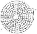
図示されるように、プロペラ501は、フィン・セットとそれを取り囲むリングとを交互に複数備え、本明細書では以後、これを「フィン−リング」構成とも呼ぶ。そのようなフィン−リング・プロペラは、典型的には、各特定の用途に専用に設計され、誘導発電機が必要とする動作周波数、周囲の水流の速度、環境的な考慮事項(例えば、魚や他の水生生物が通ることができる開口又は空隙をプロペラが有するべきか)などに基づいて直径、円周、フィン曲率及び配設偏心性、材料選択などを調整することによって、効率の改良が実現される。
As shown, the
同様に、プロペラの前に渦又はデッド・ゾーンを生成するために、隣接し合うプロペラの組を逆方向に回転させることができ(例えば図2に概略的に示されるように時計回り又は反時計回り)、これは、海洋生物を追い払う或いは保護することや、プロペラの回転効率を高めることなどを可能にする。 Similarly, adjacent propeller sets can be rotated in the opposite direction to create a vortex or dead zone in front of the propeller (eg, clockwise or counterclockwise as shown schematically in FIG. 2). This makes it possible to drive off or protect marine life, increase the rotational efficiency of the propeller, and the like.
誘導型発電機によって駆動される水流発電システムに関連して使用されるとき、プロペラに関する唯一の必須の動作要件は、それらが、発電機の動作周波数を得るのに必要とされる速度で関連する発電機シャフトを回転させることができることである。 When used in connection with hydroelectric power generation systems driven by induction generators, the only mandatory operating requirements for propellers are related to the speed at which they are needed to obtain the operating frequency of the generator The generator shaft can be rotated.
しかし、システムが全体として、地域の海洋生物との相互の影響に関して受動的なままであることが非常に望ましく、最適な性能結果は、依然として環境に優しい動作環境を維持しながらシステムが所要の電力出力を発生するときに実現される。 However, it is highly desirable that the system as a whole remain passive with respect to its interaction with local marine life, and the optimum performance results are that the system will be able to meet the required power while still maintaining an environmentally friendly operating environment. Realized when generating output.
デバイスの中心から始めて、プロペラ501は、ハブ又はシャフト部分502の周りに配設されることが分かる。ハブ又はシャフト部分502は、プロペラ501をしっかりと(例えば、カプセル化された防錆性固定具など機械的な固着によって、又はプロペラ本体又はプロペラ本体の複数の部片をシャフトに一体に溶接することによって)保持し、回転するプロペラの角度モーメントに比例する回転トルクをシャフトに与えて、発電機に送達させる。
It can be seen that starting from the center of the device, the
いくつかの実施例では、ハブ又はシャフト部分502はさらに浮上手段を備えて、シャフトへのフィン−リング・プロペラの機械的な接続を改良し、プロペラのオーバーハングを防止する。そうしない場合には、プロペラのオーバーハングがシャフトを変形する又はシャフトに応力を加える傾向がある。固着手段と同様に、このタスクに適した駆動シャフトは、現在、レコードの分野に存在し、例えば、プロペラの回転トルクを発電機シャフトに効果的に連絡する必要性に応じて、一連の歯車及び/又はクラッチや制動システムなどを備えることができる。
In some embodiments, the hub or
1つの具体的な実施例では、ボルトとワッシャのアセンブリなどの保定固定具が駆動シャフトの端部から取り外され、フィン−リング・プロペラ構造が、露出されたシャフトに被さるように摺動され、次いで固定具が再び配置され、それによりフィン−リング構造をシャフトに機械的に固着する。最適には、固定具は次いで、図6に要素601で概略的に示されるように、浮力のある耐水性カバーなどによって覆われる。
In one specific embodiment, a retention fixture such as a bolt and washer assembly is removed from the end of the drive shaft, the fin-ring propeller structure is slid over the exposed shaft, and then The fixture is repositioned, thereby mechanically securing the fin-ring structure to the shaft. Optimally, the fixture is then covered, such as by a buoyant water resistant cover, as schematically shown by
他の実施例では、中心ハブは、大きなシャフトと機械的に連絡する接続点を備え、これは、単一構造として設置又は取外し及び交換することができ、それにより、プロペラは、水中にある状態で容易に点検及び保守することができる。 In other embodiments, the central hub includes a connection point that is in mechanical communication with a large shaft, which can be installed or removed and replaced as a single structure so that the propeller is in water Can be easily inspected and maintained.
他の実施例では、システムはさらに、シャフト及びプロペラ・アセンブリのオーバーハング荷重に耐えるために浮上手段を備える。例えば、プロペラ・ハブの端部に被せて装着したノーズ・コーンに、液体発泡材又は他の軽量の流体化学物質、さらには圧縮空気を装填することができ、それにより、プロペラは、浮力のあるノーズ・コーンの後ろで駆動シャフトの周りで自由に回転でき、それによりアセンブリの重量を持ち上げ、したがって大きなオーバーハング荷重が回避される。 In another embodiment, the system further comprises levitation means to withstand overhang loads of the shaft and propeller assembly. For example, a nose cone mounted over the end of a propeller hub can be loaded with liquid foam or other lightweight fluid chemicals, as well as compressed air, so that the propeller is buoyant It can rotate freely around the drive shaft behind the nose cone, thereby lifting the weight of the assembly and thus avoiding large overhang loads.
同様に、フィン−リング構造に対する累積の流体圧に起因する抵抗を克服するために、プロペラ(特に、水流の力のほとんどを吸収する水中システムでの前側プロぺラ)を牽引取付することができる。 Similarly, to overcome resistance due to accumulated fluid pressure on the fin-ring structure, a propeller (especially a front propeller in an underwater system that absorbs most of the water flow force) can be traction mounted. .
プロペラがシャフトにどのように固着されているか、並びに浮上部材によって牽引取付及び/又は支持されているかどうかに関わらず、本明細書に示すフィン−リング設計の例示的実施例は、システム内部で実施するのに適した複数の他の関連する実施例に関しても概して同様である。 Regardless of how the propeller is secured to the shaft and whether it is traction mounted and / or supported by a levitation member, the exemplary embodiment of the fin-ring design shown herein is implemented within the system. The same is generally true for a number of other related embodiments suitable for doing so.
例えば、図5に示される実施例では、ハブ取付アセンブリ502が、第1のリング部材503によって同心に取り囲まれ、この部材503を越えて(すなわち、ハブ・アセンブリからさらに外方向に)第2のリング部材506がある。第1のリング部材503と第2のリング部材506の間に複数のフィン部材504が配設され、各フィン部材504はギャップ505によって離隔されている。
For example, in the embodiment shown in FIG. 5, the
フィン部材504の間のギャップ空間は用途によって変わるが、一般には、フィン間のギャップは、最も内側のリング(典型的にはギャップが最小である)から最も外側のリング(ギャップ空間が最大である)に向かってサイズが増加する。
The gap space between the
他の構成では、同様のサイズのギャップ、さらには外側リングよりも内側リングで大きいギャップも可能である。しかし、リングの生じ得る全表面積のほとんどがギャップではなくフィンによって利用されるほぼ中実の内側リング表面の利点は、この構造が、流体圧を構造の中心から最も外側のリングに向けて、且つデバイスの周縁部を越えて押し進める傾向があることである。 In other configurations, similarly sized gaps are possible, and even larger gaps on the inner ring than on the outer ring. However, the advantage of the nearly solid inner ring surface, where most of the total surface area that the ring can generate is utilized by the fins rather than the gap, is that this structure directs fluid pressure from the center of the structure to the outermost ring There is a tendency to push beyond the periphery of the device.
この手法は、プロペラがより簡単に回転する助けとなり、また、小さな海洋生物などがプロペラ構造を完全に避けることができるように、又は外側リングでのゆっくりと動くより大きなギャップの1つを通過することができるようにシステムの外に向けて追いやることによって環境の問題に十二分に対処する。 This approach helps the propeller to rotate more easily and passes through one of the larger gaps that move slowly on the outer ring so that small marine organisms etc. can avoid the propeller structure completely Address environmental issues more than enough by driving them out of the system.
構造に対する抵抗が減少され、より大きな回転トルクがより小さい抗力及び損失で駆動シャフトに伝達されるので、プロペラは非常にゆっくりと回転することもでき(十分な現場での結果を生み出す1つの例示的実施例では、プロペラはわずか8RPMの速度で回転する)、さらに、海洋生物が構造を避けることができることを保証し、環境への優しさ及び安全性を高める。また、ゆっくりとした回転速度により、システムは、より頑丈で、より耐久性のあるものとなり、且つ近くを浮遊するデブリや海中の物体が接触した場合にあまり損傷を受けることがなくなる。 The propeller can also rotate very slowly because resistance to the structure is reduced and greater rotational torque is transmitted to the drive shaft with less drag and loss (one illustrative example that produces sufficient field results) In an embodiment, the propeller rotates at a speed of only 8 RPM), further ensuring that marine life can avoid the structure, increasing environmental friendliness and safety. Also, the slow rotational speed makes the system more rugged and more durable, and less damaging when in contact with nearby debris and underwater objects.
次いで、追加のほぼ円形のリング509の内側に配設されたフィン507とギャップ508からなる次の同心リングが構造に追加され、そのようにして、所望の円周が実現されるまで、フィンとギャップの追加の同心リング510〜512を形成する。現在好ましい実施例では、最も外側のリングのギャップ空間514がシステムにおける最大のギャップ空間であり、個々のフィン513がシステムにおける最大の広さをもつ。
Then, the next concentric ring consisting of
最後のリング部材515は、プロペラ・システムの外周縁を取り囲み、これもまたさらに環境を保護する。なぜなら、外側リング515に偶発的に当たった海洋生物は、ゆっくりと動く構造に対してかすめる程度にしかぶつからず、水及び流体の圧力は、できるだけデバイスから離れるように向けられるからである。
The
図6(この図は概して図5の例示的実施例を示すが、ハブ取付部分が耐水キャップ601などで覆われている)の破線で囲んだ領域603で見られるように、フィン−リング・アセンブリの平面に対して測定されるフィン602のピッチを変えることができる。
The fin-ring assembly as seen in the dashed
例えば、フィンは、アセンブリ内部でのそれらの位置が中心ハブを取り囲む第1のリングから最も外側のリングに向かって進むにつれて、より大きな偏心性で配設することができる。内側リングではより平坦なピッチで、且つ外側リングにおいてはより偏心的に(すなわちアセンブリ平面に対してより垂直な平面内に)フィン602を配設することは、プロペラの周りでの水の流れを平坦に且つ滑らかにする傾向があり、それにより、(システム振動を最小限にする)優れた流体流れ特性を実現し、プロペラ構造に対する抵抗をあまり生じず、海洋生物がプロペラ・システムの中央に向かわないことを保証するようにより大きな周囲流体遠心力を提供する。
For example, the fins can be arranged with greater eccentricity as their position within the assembly proceeds from the first ring surrounding the central hub toward the outermost ring. Placing the
他方、(例えば、ボート又は潜水艦のプロペラなどで典型的なように)ハブに最も近いフィンがプロペラ全体の平面に対して測定したときに最大の偏心性を有し、次いでフィンがプロペラ・システムの外側に向けて配置されるにつれて平坦になるように構成されたフィン・アレイを有するプロペラも、振動減少、調波、及び全体のシステム性能に関して最良の結果を生み出すことができる。 On the other hand, the fin closest to the hub has the greatest eccentricity when measured against the plane of the entire propeller (as is typical for boats or submarine propellers, for example), and then the fins of the propeller system Propellers having fin arrays that are configured to be flat as they are placed outward can also produce the best results with respect to vibration reduction, harmonics, and overall system performance.
図7(図6の破線で囲んだ領域603を表す)に示される例示的実施例701では、一連の湾曲したフィン702、704、706、708が、サイズが増加していくギャップ703、705、707、709の間に配設される(最小の同心リングの開始点である中心取付ハブは、図の上部を越えて、例えばフィン702及びギャップ703の上に位置されていることに留意されたい)。
In the
図示される実施例では、フィン702、704、706、708はまた、それらが設置される位置がハブから離れるにつれてより高い偏心性で配設され、それにより、アセンブリ平面に対して測定されるフィン708の配設角度は、中心取付ハブの近くに配設されたフィン702、704、706よりも大きくなる。
In the illustrated embodiment, the
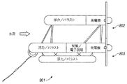
図8に示される例示的実施例では、係留された水中水流発電システムが提供され、ここでは、プロペラ・アレイ全体が牽引取付され、それにより、前部取付アレイによる力の干渉が回避され、より大きいシステム安定性及び電力効率が実現される。見て取れるように、この特定の構成は、1つ又は複数のプロペラを上側牽引取付位置と下側牽引取付位置の両方に配設することを可能にするが、複数のプロペラ・アレイをより多数又は少数の高さに配設することも可能である。 In the exemplary embodiment shown in FIG. 8, a moored submerged water current power generation system is provided, where the entire propeller array is traction mounted, thereby avoiding force interference with the front mounting array, and more Great system stability and power efficiency is achieved. As can be seen, this particular configuration allows one or more propellers to be placed in both the upper traction mounting position and the lower traction mounting position, but more or fewer propeller arrays. It is also possible to arrange them at a height.
本質的に図8に示される代替実施例の背面図である図9では、具体的であるが非限定の一実施例が、計10個のプロペラを有するプロペラ・アレイを備えていることが見られ、6個のプロペラが下側牽引取付位置に配設され、4個のプロペラが上側牽引取付位置に配設され、上側位置のアレイは、発電システムの各側に2個のプロペラにさらに分配される。 In FIG. 9, which is essentially a rear view of the alternative embodiment shown in FIG. 8, it can be seen that one specific but non-limiting embodiment comprises a propeller array having a total of ten propellers. 6 propellers are disposed at the lower traction mounting position, 4 propellers are disposed at the upper traction mounting position, and the array of upper positions is further distributed to two propellers on each side of the power generation system. Is done.
この特定の実施例は、優れた発電特性を実現し、その一方で、振動を最小にすることによって付随のシステム構造を安定化し、また、対等に合致するプロペラの対が逆の回転方向に回ることができるようにすることが分かっている。 This particular embodiment achieves excellent power generation characteristics, while stabilizing the accompanying system structure by minimizing vibrations, and a pair of matching propellers rotates in the opposite direction of rotation. I know I can do that.
そのような構成は、発電システムのいくつかの実施例に関して最適であるが、所与の動作環境で効果的と考えられるときには、実質上無制限の数の他のアレイ及び配設構成を採用することもできる。 Such a configuration is optimal for some embodiments of the power generation system, but employs a virtually unlimited number of other arrays and arrangements when deemed effective in a given operating environment. You can also.
実際上は、おそらくフィン−リング・プロペラ構造全体の組成は共通であり、例えば全体が、耐久性の、コーティングされた、又は防錆性の軽量金属からなる。しかし、フィンとリングとで異なる材料組成も可能であり、本開示の範囲から逸脱することなく、金属複合材、硬質炭素複合材、セラミックなど他の材料も問題なく使用できる。 In practice, the composition of the entire fin-ring propeller structure is probably common, for example, the whole consists of a durable, coated or rust-proof lightweight metal. However, different material compositions for the fins and rings are possible, and other materials such as metal composites, hard carbon composites, and ceramics can be used without problems without departing from the scope of this disclosure.
図10に示されるように、領域内に複数の発電構造が必要であるとき、効率を上げるために電力システムを統合することができ、電力及び制御接続は、設置されたユニットの近くに確立された中央位置、例えば制御サブステーションに戻るように連係される。このユニットの統合は、海底で、又は海中浮遊構造(若しくはその近く)で行うことができる。 As shown in FIG. 10, when multiple power generation structures are required in an area, the power system can be integrated to increase efficiency, and power and control connections are established near the installed unit. Linked back to a central location, eg, a control substation. The integration of this unit can be done on the seabed or on (or near) underwater floating structures.
制御サブステーションは、SPARなど浮遊する海面構造に設置することができ、又は場合によってはブイ・システムを使用した水中制御サブステーションでよく、これは、保守のために海面に浮上させることができ、或いは海底に固定することもできる。 The control substation can be installed on a floating sea surface structure such as SPAR, or possibly an underwater control substation using a buoy system, which can be levitated to the sea surface for maintenance, Alternatively, it can be fixed to the seabed.
深い水中では、海底の共通接続設備は、より多くの電力ケーブル及び追加の制御システムを必要とし、これらは、システムのコスト及び複雑さを増し、海面での流れにより近い位置に構成された設備よりも保守が難しい。 In deep water, submarine common connection facilities require more power cables and additional control systems, which add to the cost and complexity of the system and make it closer to the sea surface flow. Is difficult to maintain.
発電ユニットに関連付けられた浮遊スキッドと同様の要素を使用して構成された中央浮遊構造は、共通の電力収集位置を提供し、その一方で、永久的な構造を水面に浸入させない。この構成はまた、海底に敷設する必要がある長い電力及び制御ラインがより少なく、領域内での船に関して十分な喫水を残す。 A central floating structure constructed using elements similar to the floating skid associated with the power generation unit provides a common power collection location while not allowing the permanent structure to penetrate the water surface. This configuration also requires fewer long power and control lines that need to be laid on the seabed, leaving enough draft for ships in the area.
第3のタイプの共通収集位置は、海底に係留され、発電ユニットの近くで海面に浮遊する構造を備える。この手法は、多くのタイプの異なる構造を備えることができるが、(図10に示される)SPARは、その風及び波を弱める形状により、設計、並びに天候現象及びハリケーン時の安定性に関して最良の特性のいくつかを有する。 A third type of common collection location is anchored on the sea floor and comprises a structure that floats on the sea surface near the power generation unit. Although this approach can comprise many types of different structures, SPARC (shown in FIG. 10) is best in terms of design and stability during weather events and hurricanes due to its wind and wave-damping shape. Has some of the characteristics.
電力統合ステーションは、より高い伝達電圧への変換を可能にし、それにより、陸上接続電力伝達グリッドへの優れた、調整可能な電力伝送能力を実現する。また、より高い伝達電圧を可能にすることは、良好な電力伝達結果で、陸上から遠くに位置された設置を実現する。最終的な電力変換は、統合ステーション、又は海底の泥床に設置された1つ又は複数の電力変換器で実施することができる。 The power integration station enables conversion to higher transmission voltages, thereby providing superior and adjustable power transmission capabilities to land-connected power transmission grids. Also, enabling higher transmission voltages achieves installations located far from land with good power transfer results. The final power conversion can be performed at an integrated station or one or more power converters installed in the submarine mud bed.
他の変数によっては、陸上ベースの同期デバイス(例えば大型の同期電動機又は大型の可変速電子ドライバ)が必要とされることもあり、沖合の海流による発電が陸上発電グリッドよりもかなり大きいときに、そのような同期デバイスを使用して電力網を安定させる。 Depending on other variables, land-based synchronous devices (such as large synchronous motors or large variable speed electronic drivers) may be required, and when offshore ocean currents are much larger than onshore power grids, Such a synchronization device is used to stabilize the power grid.
海でのかなりの長さにわたって、DC高電圧電力伝達接続を統合構造から海岸に戻るまで延ばすことができる。個々の発電ユニットに関して必要なAC電力は、DC電圧から3相ACとして発生させて、誘導発電機に電力供給することができる。海岸で(又は海岸の近くで、さらにはその後で)、DCは、電力網又はスマート・グリッド、例えば典型的なDC電力相互接続に接続される。 Over a considerable length at sea, the DC high voltage power transfer connection can be extended from the integrated structure back to the shore. The AC power required for the individual power generation units can be generated from the DC voltage as a three-phase AC to power the induction generator. At the shore (or near the shore and even later), the DC is connected to a power grid or smart grid, such as a typical DC power interconnect.
図11に示されるように、より深い海の位置では、SPARは、浮遊スキッドによって支持する必要はなく、したがって、複数の個別の発電ユニットを調整可能に接続及び切断するのに有用な統合設備として働くことができる。図示されるように、深さ約61〜152メートル(約200〜500フィート)の水中にあるSPARは、太いポリ・ロープなど、強い固定係留手段を使用して、永久的に海底に係留させることができる。ポリ・ロープがまず一方向に巻かれ、次いで逆方向に巻かれた第2のロープによって覆われる場合、複合の交互に巻かれたラインは、非常に強くなり、ねじれや結び目が生じにくい。 As shown in FIG. 11, at deeper ocean locations, the PAR does not need to be supported by floating skids and is therefore useful as an integrated facility to adjustably connect and disconnect multiple individual power generation units. Can work. As shown, PARs in the water of about 61-152 meters (about 200-500 feet) deep can be permanently moored to the sea floor using strong fixed mooring means such as thick poly ropes. Can do. If a poly rope is first wound in one direction and then covered by a second rope wound in the opposite direction, the composite alternating wound line becomes very strong and is less prone to twists and knots.
鋼ケーブル線の重量が統合設備の浮力に関する設計態様に影響を及ぼすことを認識して、鋼撚線ケーブル係留ラインを、その中心部の中に取り囲まれた電力ケーブルと一体化することもできる。ポリ係留ケーブルは、その伸長する性質により、この用途には適していないことがある。 Recognizing that the weight of the steel cable line affects the design aspects of the buoyancy of the integrated facility, the steel stranded cable mooring line can also be integrated with the power cable surrounded in its center. Poly mooring cables may not be suitable for this application due to their elongated nature.
個々の電力ケーブルは、SPARから、海底に設置された変換器又は伝達ボックスまで延ばされ、次いで海底の下で、その最終的な到達地点に向けて延ばされる。 The individual power cables are extended from the PAR to a transducer or transmission box installed on the seabed and then under the seabed towards its final destination.
さらに別の手法は、ポリ・ロープ又は他の係留ラインの内部空隙を通して電力ケーブルを延ばすことであり、それにより、SPARから延びるラインは1つだけであり、電力ケーブルは係留ラインによって損傷から保護される。 Yet another approach is to extend the power cable through the internal air gap of a poly rope or other mooring line, so that only one line extends from the PAR and the power cable is protected from damage by the mooring line. The
次に、より強力な単一ステーション型の誘導発電システム(例えば12メートル(40フィート)以上のプロペラを利用する実施例)を考察する。図12は、4ユニット・フリップ設計発電システムの側面図であり、複数の前部取付誘導発電機が、接続部材を有する浮遊スキッドによって確立されたフレームに配設される。 Next, consider a more powerful single station induction system (eg, an embodiment utilizing a propeller of 12 meters (40 feet) or more). FIG. 12 is a side view of a four unit flip design power generation system in which a plurality of front mounted induction generators are disposed on a frame established by a floating skid having a connecting member.
(流れに応じて)少なくとも4個の12メートル(40フィート)以上のプロペラが、関連する発電ユニットと共に、回転可能なシャフトなどと機械的に連絡して配設され、プロペラは、機械的に、或いは空気圧又は液圧制御システムと連絡して配設された論理制御システムを使用して回転させることができ、本質的に上側及び下側の水平軸タービンとなる。このとき、バラスト・システムを使用して、保守及び補修のために、発電ポッドに安全に且つ効率的にアクセスできるように構造を海面に浮上させることができる。 At least four 12 meter (40 feet) or more propellers (depending on the flow) are disposed in mechanical communication with associated power generation units, such as a rotatable shaft, and the propellers mechanically, Alternatively, it can be rotated using a logic control system arranged in communication with a pneumatic or hydraulic control system, essentially resulting in upper and lower horizontal axis turbines. At this time, the ballast system can be used to raise the structure to the sea surface for safe and efficient access to the power generation pod for maintenance and repair.
図13は、6個又は8個、さらにはそれよりも多くのプロペラを有する設計にシステム機能を拡張する方法を示す、同じ構造の上面図である。 FIG. 13 is a top view of the same structure showing how to extend the system functionality to a design with 6 or 8 and even more propellers.
図14は、4ユニット・フリップ設計発電及びプロペラ・システムの前面図であり、点検中に水平面上にあり、安定性のためにY型係留ラインに取り付けられたプロペラを示す。いくつかの実施例では、より多くのプロペラがシステムに追加されるとき、スプレッダ・バー又は他の同様の装置を使用して追加の安定性を与える。 FIG. 14 is a front view of a four unit flip design power generation and propeller system, showing the propeller on a horizontal surface during inspection and attached to a Y-type mooring line for stability. In some embodiments, as more propellers are added to the system, a spreader bar or other similar device is used to provide additional stability.
図15において、4ユニット・フリップ設計発電及びプロペラ・システムが静止状態で示され、ここでは、輸送、設置、及び保守に有用な構成に反転されたものとして示されている。一実施例では、フレームと連絡して配設されたシャフトの周りで約90度以上回転することができるように、発電機ポッドがシステム・フレームに取り付けられる。この回転は、手動で達成することができ、又は論理制御システムを使用して達成することができ、空気圧回転手段又は液圧回転手段など関連する回転手段を使用してシャフトの周りでポッドを回転させることができる。 In FIG. 15, a four unit flip design power generation and propeller system is shown stationary, here shown as inverted to a configuration useful for transportation, installation, and maintenance. In one embodiment, a generator pod is attached to the system frame so that it can rotate about 90 degrees or more about a shaft disposed in communication with the frame. This rotation can be accomplished manually or can be accomplished using a logic control system, rotating the pod around the shaft using associated rotation means such as pneumatic or hydraulic rotation means. Can be made.
別の実施例では、構造が現場に送達されるとき又はプロペラ、発電機、歯車構成などの保守が必要なときに、制御された牽引の必要性に応じて、発電ポッド及びプロペラが上方向に向くようにバラストが浮遊スキッドの内部で操作される。したがって、発電ポッド及びプロペラがほぼ又は完全に海面水位よりも上にあるとき、プロペラは、風の抵抗などによる構造全体に対する不安定性を生じない。 In another embodiment, when the structure is delivered to the site or when maintenance of the propeller, generator, gear configuration, etc. is required, the power generation pod and propeller may be directed upwards depending on the need for controlled traction. The ballast is operated inside the floating skid to face. Thus, when the power generation pod and propeller are almost or completely above sea level, the propeller does not cause instability to the entire structure, such as by wind resistance.
本発明のさらに他の態様(現行の実施法では、典型的には、一般に水中エネルギー発生に関連付けられるデバイス(例えば、補助電力供給源、光ファイバ制御及び通信システム、電力ステーションを点検するために使用される付随の遠隔操作ビークルなど)を備える)は、システムの配備、位置決め、制御、及び動作に使用するための周辺機器として企図されているが、そのような他のシステム及びサブシステムは当業者には当然想到されるものであるので、すべてのそのような部品をここで非常に詳細に説明する必要はないものと思われる。 Still other aspects of the invention (in current practice, typically used to check devices commonly associated with underwater energy generation (eg, auxiliary power supplies, fiber optic control and communication systems, power stations) Are provided as peripheral devices for use in system deployment, positioning, control, and operation, although such other systems and subsystems are known to those skilled in the art. Is naturally conceivable, so it would not be necessary to describe all such parts in great detail here.
本発明を、いくつかの例示的実施例に関して上で詳細に図示して説明してきたが、当業者は、上記の説明に対する小さな変更も理解されよう。本発明の精神又は範囲から逸脱することなく様々な修正、省略、及び追加を施すこともできる。 Although the present invention has been illustrated and described in detail above with respect to several exemplary embodiments, those skilled in the art will recognize minor modifications to the above description. Various modifications, omissions and additions may be made without departing from the spirit or scope of the invention.
101 水流発電システム
102 浮上管
103 バラスト管
104 誘導型発電ユニット
105 シャフト駆動プロペラ
201 発電システム
204 誘導発電機ユニット
205 誘導発電機ユニット
206 プロペラ
301 内部バラスト・システム
302 空気制御源
303 第1の隔離チャンバ
304 第2の隔離チャンバ
306 最終の隔離チャンバ
307 圧力安全弁
308 水流弁
309 空気出口弁
401 システム
402 第1の浮上管
403 第2の浮上管
404 接続用の格子状本体部分
405 誘導発電機
406 誘導発電機
407 プロペラ
408 係留部材
409 係留部材
410 アンカ係留綱
411 アンカ部材
501 プロペラ
502 ハブ又はシャフト部分
503 第1のリング部材
504 フィン部材
505 ギャップ
506 第2のリング部材
507 フィン
508 ギャップ
510 同心リング
511 同心リング
512 同心リング
514 ギャップ空間
101
Claims (6)
複数のプロペラを備えた1又は複数の水中誘導型発電ユニットを、前記プロペラが水流に応答して駆動シャフトの周りで回転するように、1又は複数の水中浮遊チャンバと機械的に連絡して配設するステップと、
前記複数のプロペラが水面にほぼ平行に配設されるように前記発電ユニットを前記水中浮遊チャンバに対して回転させるステップと
を含む方法。 A method of installing and maintaining an underwater water current power generation system,
One or more water induction generator unit with a multiple propeller, the propeller for rotation about the drive shaft in response to the water flow, one or more and waterborne chamber and mechanical communication Arranging, and
Rotating the power generation unit relative to the submerged floating chamber such that the plurality of propellers are disposed substantially parallel to the water surface.
Applications Claiming Priority (2)
| Application Number | Priority Date | Filing Date | Title |
|---|---|---|---|
| US13/454,608 US8847421B2 (en) | 2008-07-16 | 2012-04-24 | Subsystems for a water current power generation system |
| US13/454,608 | 2012-04-24 |
Related Parent Applications (1)
| Application Number | Title | Priority Date | Filing Date |
|---|---|---|---|
| JP2012205388A Division JP2013227962A (en) | 2012-04-24 | 2012-09-19 | Subsystem for water current power generation system |
Publications (2)
| Publication Number | Publication Date |
|---|---|
| JP2013227964A JP2013227964A (en) | 2013-11-07 |
| JP6055652B2 true JP6055652B2 (en) | 2016-12-27 |
Family
ID=46051941
Family Applications (3)
| Application Number | Title | Priority Date | Filing Date |
|---|---|---|---|
| JP2012205388A Pending JP2013227962A (en) | 2012-04-24 | 2012-09-19 | Subsystem for water current power generation system |
| JP2012240064A Pending JP2013227963A (en) | 2012-04-24 | 2012-10-31 | Subsystem for water current power generation system |
| JP2012240065A Active JP6055652B2 (en) | 2012-04-24 | 2012-10-31 | Subsystem for hydroelectric power generation system |
Family Applications Before (2)
| Application Number | Title | Priority Date | Filing Date |
|---|---|---|---|
| JP2012205388A Pending JP2013227962A (en) | 2012-04-24 | 2012-09-19 | Subsystem for water current power generation system |
| JP2012240064A Pending JP2013227963A (en) | 2012-04-24 | 2012-10-31 | Subsystem for water current power generation system |
Country Status (15)
| Country | Link |
|---|---|
| EP (3) | EP2657512B1 (en) |
| JP (3) | JP2013227962A (en) |
| KR (3) | KR101548038B1 (en) |
| AP (3) | AP3871A (en) |
| AU (1) | AU2012205263A1 (en) |
| BR (3) | BR122013011260B1 (en) |
| DK (2) | DK2657124T3 (en) |
| EA (3) | EA021599B1 (en) |
| ES (2) | ES2576002T3 (en) |
| MX (2) | MX342596B (en) |
| PH (2) | PH12013000111A1 (en) |
| PT (2) | PT2657512E (en) |
| TW (3) | TWI482390B (en) |
| WO (1) | WO2013162520A2 (en) |
| ZA (2) | ZA201306333B (en) |
Families Citing this family (10)
| Publication number | Priority date | Publication date | Assignee | Title |
|---|---|---|---|---|
| GB2524252A (en) * | 2014-03-17 | 2015-09-23 | Marine Current Turbines Ltd | Water current turbine |
| WO2016025038A1 (en) * | 2014-08-12 | 2016-02-18 | Anadarko Petroleum Corporation | Systems and methods for transportation and maintenance of a water current power generation system |
| JP6248017B2 (en) * | 2014-09-12 | 2017-12-13 | 三菱重工業株式会社 | Start-up method and start-up control device for ocean current power generator |
| RU167333U1 (en) * | 2016-04-14 | 2017-01-10 | Виталина Владимировна Журавлева | FOLDING MICROHES |
| CN107792326A (en) * | 2016-08-31 | 2018-03-13 | 王斌 | Split type submersible |
| DE102018216785A1 (en) * | 2018-09-28 | 2020-04-02 | Siemens Aktiengesellschaft | Power supply system for a water-bound facility |
| JP7200733B2 (en) * | 2019-02-19 | 2023-01-10 | 株式会社Ihi | Floating water current generator |
| CN111810349B (en) * | 2020-06-10 | 2022-01-18 | 中国矿业大学 | Offshore tidal power generation device |
| CN114838042B (en) * | 2022-05-16 | 2023-11-28 | 海洋石油工程股份有限公司 | Marine organism-preventing butt-joint locking mechanism for shallow water underwater facilities |
| CN114954866A (en) * | 2022-05-31 | 2022-08-30 | 南通理工学院 | Intelligent monitor for offshore underwater monitoring |
Family Cites Families (36)
| Publication number | Priority date | Publication date | Assignee | Title |
|---|---|---|---|---|
| SE424708B (en) * | 1977-06-27 | 1982-08-09 | Socared Sa | ELASTLINA |
| US4640212A (en) * | 1978-06-21 | 1987-02-03 | Socared S.A. | Rope and a mooring device, particularly for clamping goods mooring ships and anchoring floating landing stages, buoys, navigation marks and the like |
| GB2053303B (en) * | 1979-07-20 | 1983-12-14 | Platts M J | Elastic tie member |
| IT1139379B (en) * | 1981-08-18 | 1986-09-24 | Tecnomare Spa | SYSTEM FOR THE RECOVERY OF THE ENERGY OF THE WAVE MOTOR AND ITS TRANSFORMATION INTO USEFUL ENERGY |
| DK155454C (en) * | 1986-12-03 | 1989-08-07 | Hans Marius Pedersen | LIQUID HYDRAULIC POWER PLANT FOR USE IN SEA AND FLOOD STREAMS FOR ENERGY IMPACT |
| GB9111013D0 (en) * | 1991-05-22 | 1991-07-17 | I T Power Limited | Floating water current turbine system |
| GB9508476D0 (en) * | 1995-04-26 | 1995-06-14 | Brupat Ltd | Mooring bed assessment apparatus and method |
| US6091161A (en) * | 1998-11-03 | 2000-07-18 | Dehlsen Associates, L.L.C. | Method of controlling operating depth of an electricity-generating device having a tethered water current-driven turbine |
| IL133050A (en) * | 1998-12-07 | 2003-12-10 | Inventio Ag | Device for identification of need to replace synthetic fiber ropes |
| US6531788B2 (en) * | 2001-02-22 | 2003-03-11 | John H. Robson | Submersible electrical power generating plant |
| EP1467091B1 (en) * | 2001-07-11 | 2012-02-29 | Hydra Tidal Energy Technology AS | Floating water current turbine with counter rotating coaxial rotors |
| GB0221896D0 (en) * | 2002-09-20 | 2002-10-30 | Soil Machine Dynamics Ltd | Apparatus for generating electrical power from tidal water movement |
| US6982498B2 (en) * | 2003-03-28 | 2006-01-03 | Tharp John E | Hydro-electric farms |
| US8072089B2 (en) * | 2003-05-29 | 2011-12-06 | Krouse Wayne F | Fluid energy apparatus and method |
| GB0427197D0 (en) * | 2004-12-11 | 2005-01-12 | Johnston Barry | Tidal power generating apparatus |
| GB2434410B (en) * | 2006-01-18 | 2009-09-16 | Michael Torr Todman | Underwater turbine mounting |
| EP2295792B1 (en) * | 2006-02-02 | 2016-11-02 | Minesto AB | A submersible plant |
| AU2006340933B2 (en) * | 2006-03-29 | 2011-12-22 | Seabased Ab | A system for generating electric energy |
| RU2405966C2 (en) * | 2006-03-29 | 2010-12-10 | Сибэйсд Аб | System for electrical energy production |
| JP2008063960A (en) * | 2006-09-05 | 2008-03-21 | Masataka Murahara | Ocean float type wind and water turbine fluid extracting power generating facilities |
| CA2667134C (en) * | 2006-10-20 | 2014-12-09 | Ocean Renewable Power Company, Llc | Submersible turbine-generator unit for ocean and tidal currents |
| RS20070022A (en) * | 2007-01-22 | 2008-08-07 | Nenad Paunović | Mobile underwater platform for exploitation of river and water steam flow energy |
| GB0705476D0 (en) * | 2007-03-22 | 2007-05-02 | Marine Current Turbines Ltd | Deep water water current turbine installations |
| TW200900581A (en) * | 2007-06-28 | 2009-01-01 | Jen-Huan Chang | Floating and diving platform for ocean current power generation system |
| JP5189647B2 (en) * | 2007-06-29 | 2013-04-24 | アクアンティス,インコーポレーテッド | Multipoint mooring and stabilization system and control method for submersible turbines using flow |
| JP5320527B2 (en) * | 2008-02-21 | 2013-10-23 | 古河電気工業株式会社 | High strength cable |
| WO2009126995A1 (en) * | 2008-04-14 | 2009-10-22 | Atlantis Resources Corporation Pte Limited | Central axis water turbine |
| MX2009005202A (en) * | 2008-05-14 | 2009-11-27 | Schlumberger Technology Bv | Torque-balanced electrical cable. |
| US7936077B2 (en) * | 2008-05-19 | 2011-05-03 | Lehoczky Kalman N | Internal fluid handling for hydro-generator submerged in water |
| NO328410B1 (en) * | 2008-06-27 | 2010-02-15 | Hydra Tidal Energy Technology | System for anchoring a floating plant for production of energy from streams in a body of water |
| WO2010008368A1 (en) * | 2008-07-16 | 2010-01-21 | Anadarko Petroleum Corporation | Water current power generation system |
| WO2011056249A2 (en) * | 2009-11-09 | 2011-05-12 | Anadarko Petroleum Corporation | Fin-ring propeller for a water current power generation system |
| FR2953552B1 (en) * | 2009-12-04 | 2011-12-09 | Technip France | CONNECTION ASSEMBLY OF A FLEXIBLE TUBULAR DRIVE TO AN UNDERWATER INSTALLATION. |
| EP2518310B1 (en) * | 2009-12-21 | 2015-06-03 | Fundacion Tecnalia Research & Innovation | Electrical interconnection system between at least one electricity generator and one electricity transfer system, in a marine environment |
| RU2548568C2 (en) * | 2010-02-01 | 2015-04-20 | 3М Инновейтив Пропертиз Компани | Stranded thermoplastic polymer composite cables, methods for production and use thereof |
| US8558403B2 (en) * | 2010-09-27 | 2013-10-15 | Thomas Rooney | Single moored offshore horizontal turbine train |
-
2012
- 2012-04-24 WO PCT/US2012/034806 patent/WO2013162520A2/en active Application Filing
- 2012-07-20 AU AU2012205263A patent/AU2012205263A1/en not_active Abandoned
- 2012-07-23 EA EA201270725A patent/EA021599B1/en unknown
- 2012-07-23 EA EA201270726A patent/EA018743B1/en unknown
- 2012-07-23 EA EA201270665A patent/EA201270665A1/en unknown
- 2012-07-30 AP AP2012006496A patent/AP3871A/en active
- 2012-07-30 AP AP2012006495A patent/AP2012006495A0/en unknown
- 2012-07-30 AP AP2012006399A patent/AP2012006399A0/en unknown
- 2012-08-23 TW TW101130672A patent/TWI482390B/en active
- 2012-08-23 TW TW101130671A patent/TWI598268B/en active
- 2012-08-23 TW TW101130673A patent/TWI548810B/en active
- 2012-09-05 KR KR1020120098289A patent/KR101548038B1/en active IP Right Grant
- 2012-09-05 KR KR1020120098042A patent/KR101883751B1/en active IP Right Grant
- 2012-09-05 KR KR1020120098290A patent/KR101548039B1/en active IP Right Grant
- 2012-09-13 BR BR122013011260-0A patent/BR122013011260B1/en active IP Right Grant
- 2012-09-13 BR BR102012023160-3A patent/BR102012023160B1/en active IP Right Grant
- 2012-09-13 BR BR122013011266-9A patent/BR122013011266B1/en active IP Right Grant
- 2012-09-19 JP JP2012205388A patent/JP2013227962A/en active Pending
- 2012-09-24 MX MX2013003493A patent/MX342596B/en unknown
- 2012-09-24 MX MX2012011042A patent/MX2012011042A/en active IP Right Grant
- 2012-10-31 JP JP2012240064A patent/JP2013227963A/en active Pending
- 2012-10-31 JP JP2012240065A patent/JP6055652B2/en active Active
-
2013
- 2013-04-17 PH PH12013000111A patent/PH12013000111A1/en unknown
- 2013-04-17 PH PH12013000112A patent/PH12013000112B1/en unknown
- 2013-04-23 PT PT131651473T patent/PT2657512E/en unknown
- 2013-04-23 EP EP13165147.3A patent/EP2657512B1/en active Active
- 2013-04-23 PT PT131651531T patent/PT2657124T/en unknown
- 2013-04-23 EP EP13165153.1A patent/EP2657124B1/en active Active
- 2013-04-23 ES ES13165147.3T patent/ES2576002T3/en active Active
- 2013-04-23 EP EP13164887.5A patent/EP2657122A3/en not_active Withdrawn
- 2013-04-23 ES ES13165153.1T patent/ES2582490T3/en active Active
- 2013-04-23 DK DK13165153.1T patent/DK2657124T3/en active
- 2013-04-23 DK DK13165147.3T patent/DK2657512T3/en active
- 2013-08-22 ZA ZA2013/06333A patent/ZA201306333B/en unknown
- 2013-08-22 ZA ZA2013/06332A patent/ZA201306332B/en unknown
Also Published As
Similar Documents
| Publication | Publication Date | Title |
|---|---|---|
| JP6055652B2 (en) | Subsystem for hydroelectric power generation system | |
| TWI486519B (en) | Fin-ring propeller for a water current power generation system | |
| US8847421B2 (en) | Subsystems for a water current power generation system | |
| US20170175699A1 (en) | Systems and Methods for Transportation and Maintenance of a Water Current Power Generation System | |
| AU2012213966B2 (en) | Subsystems for a water current power generation system | |
| AU2014277769B9 (en) | Subsystems for a water current power generation system | |
| OA17018A (en) | Subsystems for a water current power generation system. | |
| OA16967A (en) | Power distribution and transmission systems for a water current power generation system. |
Legal Events
| Date | Code | Title | Description |
|---|---|---|---|
| A621 | Written request for application examination |
Free format text: JAPANESE INTERMEDIATE CODE: A621 Effective date: 20150320 |
|
| A977 | Report on retrieval |
Free format text: JAPANESE INTERMEDIATE CODE: A971007 Effective date: 20160122 |
|
| A131 | Notification of reasons for refusal |
Free format text: JAPANESE INTERMEDIATE CODE: A131 Effective date: 20160202 |
|
| A601 | Written request for extension of time |
Free format text: JAPANESE INTERMEDIATE CODE: A601 Effective date: 20160502 |
|
| A601 | Written request for extension of time |
Free format text: JAPANESE INTERMEDIATE CODE: A601 Effective date: 20160701 |
|
| A521 | Request for written amendment filed |
Free format text: JAPANESE INTERMEDIATE CODE: A523 Effective date: 20160725 |
|
| TRDD | Decision of grant or rejection written | ||
| A01 | Written decision to grant a patent or to grant a registration (utility model) |
Free format text: JAPANESE INTERMEDIATE CODE: A01 Effective date: 20161108 |
|
| A61 | First payment of annual fees (during grant procedure) |
Free format text: JAPANESE INTERMEDIATE CODE: A61 Effective date: 20161205 |
|
| R150 | Certificate of patent or registration of utility model |
Ref document number: 6055652 Country of ref document: JP Free format text: JAPANESE INTERMEDIATE CODE: R150 |
|
| R250 | Receipt of annual fees |
Free format text: JAPANESE INTERMEDIATE CODE: R250 |
|
| R250 | Receipt of annual fees |
Free format text: JAPANESE INTERMEDIATE CODE: R250 |
|
| R250 | Receipt of annual fees |
Free format text: JAPANESE INTERMEDIATE CODE: R250 |
|
| R250 | Receipt of annual fees |
Free format text: JAPANESE INTERMEDIATE CODE: R250 |
|
| R250 | Receipt of annual fees |
Free format text: JAPANESE INTERMEDIATE CODE: R250 |