JP6053422B2 - Imaging apparatus and imaging method - Google Patents
Imaging apparatus and imaging method Download PDFInfo
- Publication number
- JP6053422B2 JP6053422B2 JP2012210150A JP2012210150A JP6053422B2 JP 6053422 B2 JP6053422 B2 JP 6053422B2 JP 2012210150 A JP2012210150 A JP 2012210150A JP 2012210150 A JP2012210150 A JP 2012210150A JP 6053422 B2 JP6053422 B2 JP 6053422B2
- Authority
- JP
- Japan
- Prior art keywords
- shake
- axis
- correction amount
- around
- optical axis
- Prior art date
- Legal status (The legal status is an assumption and is not a legal conclusion. Google has not performed a legal analysis and makes no representation as to the accuracy of the status listed.)
- Active
Links
Images


Description
本発明は、撮像装置における画像の振れを補正する技術に関する。 The present invention relates to a technique for correcting image shake in an imaging apparatus.
近年、撮像装置の振れに起因して生じる像振れを補正する技術が進歩している。これに伴い、撮像装置が光軸回りに回転することによって、撮像画像の回転や、撮像装置が被写体に対して傾くことによって撮像画像が台形状に歪む像振れ(あおり)等を補正する像振れ補正機能が普及してきている。 2. Description of the Related Art In recent years, techniques for correcting image blur caused by shake of an image pickup apparatus have advanced. Along with this, the image pickup device rotates around the optical axis, thereby rotating the picked-up image, and image shake that corrects image shake or the like that the picked-up image is distorted in a trapezoid shape when the image pickup device is tilted with respect to the subject. Correction functions are becoming popular.
撮像画像が回転する像振れを補正する方法としては、例えば、特許文献1のように撮像素子を機械的に回転することにより補正する方法がある。また、例えば、撮像画像が回転する像振れや台形状に歪む像振れを補正する方法として、特許文献2のように撮像画像の画像変形量を算出し、その画像変形量を打ち消すように画像を変形する方法が知られている。
As a method for correcting the image blur caused by the rotation of the captured image, for example, there is a method for correcting the image blur by mechanically rotating the image sensor as disclosed in
しかしながら、上記従来例では以下のような問題点があった。 However, the conventional example has the following problems.
撮像装置の振れを角速度センサの出力から検出して像振れを補正している場合は、撮像光学系の光軸に垂直な平面上の軸回りの振れ(YAW及びPITCH方向)と、光軸回りの振れ(ROLL方向)を、角速度センサによって検出する。このとき、角速度センサは電子回路基板上に実装される際の組み立て上の誤差は免れない。この誤差によって、例えばYAW方向に撮像装置をパンニングする等の大きな振れが発生したときに、ROLLあるいはPITCH方向の角速度センサの出力も変動してしまう。 When the image shake is corrected by detecting the shake of the imaging device from the output of the angular velocity sensor, the shake around the axis (YAW and PITCH directions) on the plane perpendicular to the optical axis of the imaging optical system, and the optical axis Is detected by the angular velocity sensor. At this time, the angular velocity sensor is subject to assembly errors when mounted on the electronic circuit board. Due to this error, the output of the angular velocity sensor in the ROLL or PITCH direction also fluctuates when a large shake such as panning the imaging device in the YAW direction occurs.
この場合、YAW方向にパンニングしたときに画像が回転(ROLL方向)したり、縦方向(PITCH方向)の台形歪み(あおり)が発生すると、映像としては非常に目立ち、ユーザーに不快感を与える程の不自然な映像となる可能性があった。 In this case, when the image is rotated (ROLL direction) or trapezoidal distortion (tilt) in the vertical direction (PITCH direction) occurs when panning in the YAW direction, the image is very conspicuous and uncomfortable for the user. There was a possibility of becoming an unnatural image.
本発明は上述した課題に鑑みてなされたものであり、その目的は、角速度センサの検出軸のズレによって発生する他軸への悪影響の度合いを最小限に抑え、良好な像振れ補正効果が得られるようにした撮像装置を提供することである。 The present invention has been made in view of the above-described problems, and an object of the present invention is to minimize the adverse effect on the other axis caused by the deviation of the detection axis of the angular velocity sensor and to obtain a good image blur correction effect. An imaging device is provided.
本発明に係わる撮像装置は、光軸に垂直な第1の軸回りの振れ、及び、前記第1の軸及び前記光軸に垂直な第2の軸回りの振れ、及び、前記光軸回りの振れを検出する振れ検出手段にて検出された第1の軸回りの振れの情報及び前記第2の軸回りの振れの情報に基づいて、撮像画像の並進方向の振れによる像振れの補正量を演算する並進補正量演算手段と、前記振れ検出手段により検出された光軸回りの振れの情報に基づいて、前記撮像画像の光軸回りの振れによる像振れの補正量を演算する回転補正量演算手段と、前記並進補正量演算手段及び前記回転補正量演算手段により演算された像振れの補正量に基づいて、像振れを補正する像振れ補正手段を制御する第1の制御手段と、前記第1の軸回りの振れの情報が所定の閾値より大きい時間が所定時間以上継続したとき、パンニングあるいはチルティングされた状態であると判定し、前記パンニングあるいはチルティングされた状態であると判定された場合、前記パンニングあるいはチルティングされた状態であると判定されない場合に比べて、前記撮像画像の光軸回りの像振れの補正量を小さくする第2の制御手段と、を備えることを特徴とする。
また、本発明に係わる撮像装置は、光軸に垂直な第1の軸回りの振れ、及び、前記第1の軸及び前記光軸に垂直な第2の軸回りの振れ、及び、前記光軸回りの振れを検出する振れ検出手段にて検出された第1の軸回りの振れの情報及び前記第2の軸回りの振れの情報に基づいて、撮像画像の並進方向の振れによる像振れの補正量を演算する並進補正量演算手段と、前記振れ検出手段により検出された光軸回りの振れの情報に基づいて、前記撮像画像の光軸回りの振れによる像振れの補正量を演算する回転補正量演算手段と、前記並進補正量演算手段及び前記回転補正量演算手段により演算された像振れの補正量に基づいて、像振れを補正する像振れ補正手段を制御する第1の制御手段と、前記撮像画像の光軸回りの像振れの補正量を制限する第2の制御手段と、を備え、前記第2の制御手段は、前記第1の軸回りの振れの情報が前記所定の閾値より大きい時間が所定時間以上継続した場合、前記第1の軸回りの振れの情報が前記所定の閾値より大きい時間が所定時間以上継続しない場合に比べて、前記撮像画像の光軸回りの像振れの補正量を小さくするために、前記回転補正量演算手段のハイパスフィルタのカットオフ周波数を高くすることを特徴とする。
また、本発明に係わる撮像装置は、光軸に垂直な第1の軸回りの振れ、及び、前記第1の軸及び前記光軸に垂直な第2の軸回りの振れ、及び、前記光軸回りの振れを検出する振れ検出手段にて検出された第1の軸回りの振れの情報及び前記第2の軸回りの振れの情報に基づいて、撮像画像の並進方向の振れによる像振れの補正量を演算する並進補正量演算手段と、前記振れ検出手段により検出された光軸回りの振れの情報に基づいて、前記撮像画像の光軸回りの振れによる像振れの補正量を演算する回転補正量演算手段と、前記並進補正量演算手段及び前記回転補正量演算手段により演算された像振れの補正量に基づいて、像振れを補正する像振れ補正手段を制御する第1の制御手段と、前記撮像画像の光軸回りの像振れの補正量を制限する第2の制御手段と、を備え、前記第2の制御手段は、前記第1の軸回りの振れの情報が前記所定の閾値より大きい時間が所定時間以上継続した場合、前記第1の軸回りの振れの情報が前記所定の閾値より大きい時間が所定時間以上継続しない場合に比べて、前記撮像画像の光軸回りの像振れの補正量を小さくするために、前記回転補正量演算手段における積分手段の時定数を短くすることを特徴とする。
また、本発明に係わる撮像装置は、光軸に垂直な第1の軸回りの振れ、及び、前記第1の軸及び前記光軸に垂直な第2の軸回りの振れ、及び、前記光軸回りの振れを検出する振れ検出手段にて検出された第1の軸回りの振れの情報及び前記第2の軸回りの振れの情報に基づいて、撮像画像の並進方向の振れによる像振れの補正量を演算する並進補正量演算手段と、前記振れ検出手段により検出された光軸回りの振れの情報に基づいて、前記撮像画像の光軸回りの振れによる像振れの補正量を演算する回転補正量演算手段と、前記並進補正量演算手段及び前記回転補正量演算手段により演算された像振れの補正量に基づいて、像振れを補正する像振れ補正手段を制御する第1の制御手段と、前記撮像画像の光軸回りの像振れの補正量を制限する第2の制御手段と、を備え、前記第2の制御手段は、前記第1の軸回りの振れの情報が前記所定の閾値より大きい時間が所定時間以上継続した場合、前記第1の軸回りの振れの情報が前記所定の閾値より大きい時間が所定時間以上継続しない場合に比べて、前記撮像画像の光軸回りの像振れの補正量を小さくするために、前記回転補正量演算手段の演算値の限界を小さくすることを特徴とする。
An imaging apparatus according to the present invention includes a shake around a first axis perpendicular to an optical axis, a shake around a second axis perpendicular to the first axis and the optical axis, and a shake around the optical axis. Based on the information about the shake about the first axis and the information about the shake about the second axis detected by the shake detection means for detecting the shake, the correction amount of the image shake due to the shake in the translation direction of the captured image is calculated. Translation correction amount calculation means for calculating, and rotation correction amount calculation for calculating a correction amount of image shake due to shake around the optical axis of the captured image based on information about shake around the optical axis detected by the shake detection means and means, based on the correction amount of the image blur is more operation on the translational compensation amount calculating means and the prior SL rotational compensation amount calculating means, first control means for controlling the image blur correcting means for correcting an image blur, Time when the shake information about the first axis is larger than a predetermined threshold When it has been determined that it has been panned or tilted when it has continued for a predetermined time or more, and when it has been determined that it has been panned or tilted, it has not been determined that it has been panned or tilted And a second control means for reducing a correction amount of image blur around the optical axis of the captured image .
In addition, the imaging apparatus according to the present invention includes a shake around a first axis perpendicular to the optical axis, a shake around a second axis perpendicular to the first axis and the optical axis, and the optical axis. Correction of image blur due to shake in the translational direction of the captured image based on information on shake around the first axis and information on shake around the second axis detected by the shake detection means for detecting around shake Translation correction amount calculating means for calculating the amount, and rotation correction for calculating a correction amount of the image shake due to the shake around the optical axis of the captured image based on the information about the shake around the optical axis detected by the shake detection means A first control unit that controls an image blur correction unit that corrects an image blur based on an amount calculation unit, and an image blur correction amount calculated by the translation correction amount calculation unit and the rotation correction amount calculation unit; Limiting the amount of image blur correction around the optical axis of the captured image Two control means, wherein the second control means is arranged around the first axis when the information about the shake about the first axis continues for a predetermined time or longer than the predetermined threshold. The high-pass filter of the rotation correction amount calculation means is used to reduce the amount of correction of image blur around the optical axis of the captured image, compared to the case where the time when the shake information is greater than the predetermined threshold does not continue for a predetermined time. It is characterized by increasing the cut-off frequency.
In addition, the imaging apparatus according to the present invention includes a shake around a first axis perpendicular to the optical axis, a shake around a second axis perpendicular to the first axis and the optical axis, and the optical axis. Correction of image blur due to shake in the translational direction of the captured image based on information on shake around the first axis and information on shake around the second axis detected by the shake detection means for detecting around shake Translation correction amount calculating means for calculating the amount, and rotation correction for calculating a correction amount of the image shake due to the shake around the optical axis of the captured image based on the information about the shake around the optical axis detected by the shake detection means. A first control unit that controls an image blur correction unit that corrects an image blur based on an amount calculation unit, and an image blur correction amount calculated by the translation correction amount calculation unit and the rotation correction amount calculation unit; Limiting the amount of image blur correction around the optical axis of the captured image Two control means, wherein the second control means is arranged around the first axis when the information about the shake about the first axis continues for a predetermined time or longer than the predetermined threshold. In order to reduce the correction amount of the image blur around the optical axis of the captured image compared to the case where the time when the shake information is longer than the predetermined threshold does not continue for a predetermined time or longer, the integration unit in the rotation correction amount calculation unit The time constant of is shortened.
In addition, the imaging apparatus according to the present invention includes a shake around a first axis perpendicular to the optical axis, a shake around a second axis perpendicular to the first axis and the optical axis, and the optical axis. Correction of image blur due to shake in the translational direction of the captured image based on information on shake around the first axis and information on shake around the second axis detected by the shake detection means for detecting around shake Translation correction amount calculating means for calculating the amount, and rotation correction for calculating a correction amount of the image shake due to the shake around the optical axis of the captured image based on the information about the shake around the optical axis detected by the shake detection means. A first control unit that controls an image blur correction unit that corrects an image blur based on an amount calculation unit, and an image blur correction amount calculated by the translation correction amount calculation unit and the rotation correction amount calculation unit; Limiting the amount of image blur correction around the optical axis of the captured image Two control means, wherein the second control means is arranged around the first axis when the information about the shake about the first axis continues for a predetermined time or longer than the predetermined threshold. Compared to the case where the time when the shake information is longer than the predetermined threshold does not continue for a predetermined time or more, the calculated value of the rotation correction amount calculating means is used to reduce the correction amount of the image shake around the optical axis of the captured image. It is characterized by reducing the limit of.
本発明によれば、角速度センサの検出軸のズレによって発生する他軸への悪影響の度合いを最小限に抑え、良好な像振れ補正効果が得られる撮像装置を提供することが可能となる。 According to the present invention, it is possible to provide an imaging apparatus that can minimize the degree of adverse effects on other axes caused by the deviation of the detection axis of the angular velocity sensor and obtain a good image blur correction effect.
以下、本発明の実施形態について、添付図面を参照して詳細に説明する。 Hereinafter, embodiments of the present invention will be described in detail with reference to the accompanying drawings.
(第1の実施形態)
図1は、本発明の第1の実施形態に係る像振れ補正装置を備えた撮像装置の一例として、デジタルビデオカメラの構成を示すブロック図である。以下、図1の撮像装置100の各構成部とその一例の動作について具体的に説明する。
(First embodiment)
FIG. 1 is a block diagram showing a configuration of a digital video camera as an example of an imaging apparatus provided with an image shake correction apparatus according to the first embodiment of the present invention. Hereinafter, each component of the
角速度センサ102は、撮像装置100の振れ(撮影光軸に垂直な平面上の2軸回りの振れ、及び光軸回りの振れ)を角速度信号として検出し、その角速度信号をA/D変換器103に供給する。このときの2軸は、撮像光学系の光軸(Z軸とする)に垂直な2軸(X軸とY軸)とすると、この場合の角速度検出方向をYAW及びPITCH方向であり、また光軸回りとはROLL方向であるとする。A/D変換器103は、角速度センサ102からの角速度信号をそれぞれデジタル化して、角速度データとしてμCOM101内部の画像変形量演算部200に供給する。
The
撮像光学系106は、ズーミング、フォーカシング等の動作を行い、被写体像を撮像素子107に結像する。ズームエンコーダ104は、撮像光学系106の中の変倍光学系105の位置(ズーム位置)を検出し、μCOM101内部の画像変形量演算部200に出力する。
The imaging
画像変形量演算部200は、上記角速度データ及びズームエンコーダ104の出力を用いて、撮像画像の振れを補正するための画像変形量を算出し、画像変形部110に算出した画像変形量を設定する。画像変形量演算部200の処理の詳細は後述する。
The image deformation
撮像素子107は、撮像光学系106によって結像された被写体像を撮像画像信号としての電気信号に変換し、信号処理部108に供給する。信号処理部108は、撮像素子107により得られた信号から、例えばNTSCフォーマットに準拠したビデオ信号(映像信号)を生成して画像メモリ109に供給する。
The
画像変形部110は、画像変形量演算部200で算出された画像変形量に基づいて、画像メモリ109に格納された画像を変形することによって撮像画像の振れを補正し、記録制御部111及び表示制御部113に出力する。表示制御部113は、画像変形部110から供給された映像信号を出力して表示デバイス114に画像を表示させる。表示制御部113は表示デバイス114を駆動し、表示デバイス114は液晶表示素子(LCD)等により画像を表示する。また、記録制御部111は、記録開始や終了の指示に用いる操作部(不図示)によって映像信号の記録が指示された場合、画像変形部110から供給された映像信号を記録媒体112に出力し、記録させる。記録媒体112は、半導体メモリ等の情報記録媒体やハードディスク等の磁気記録媒体である。
The
画像変形部110は、例えば射影変換等の幾何変換を用いて画像変形を行う。具体的には、変形前の画像(画像メモリ109に格納された画像)中の画素座標を(X0,Y0)(ただし、撮像光学系106の光軸に対応した撮像画像の中心を原点とする)とし、変形後の画像(画像変形部110の出力画像)中の画素座標を(X1,Y1)として、同次座標で表現すると、(式1)のように記述することができる。
The

(式1)の左辺と右辺は同値関係(左辺または右辺に任意の倍率をかけても意味が変わらない)を示し、通常の等号では(式2)(式3)となる。 The left side and the right side of (Formula 1) show an equivalence relationship (the meaning does not change even if an arbitrary magnification is applied to the left side or the right side), and in the normal equal sign, (Formula 2) (Formula 3).
また(式1)において、3×3の行列は一般的に射影変換行列と呼ばれ、行列の要素h1〜h8は、画像変形量演算部200が設定する。なお、以下の説明では、画像変形部110の画像変形は、射影変換を用いることとして説明を行うが、例えばアフィン変換等、如何なる変形方法を用いても良い。
In (Expression 1), a 3 × 3 matrix is generally called a projective transformation matrix, and the elements h1 to h8 of the matrix are set by the image deformation
次に、画像変形量演算部200によって行われる処理の詳細について説明する。画像変形量演算部200では、角速度センサ102の出力から算出される撮像装置の振れ角度と、ズームエンコーダ104から算出される撮像光学系106の焦点距離とを用いて、画像変形部110の画像変形量を算出する。具体的には、(式1)の射影変換行列を算出する。
Next, details of processing performed by the image deformation
ここで、振れ角度と撮像光学系106の焦点距離を用いた射影変換行列の算出方法について、以下に説明する。図2(a)は、撮像装置による被写体の撮像面への投影を、ピンホールカメラモデルで図示したものである。図2(a)において、XYZ空間座標の原点(0,0,0)は、ピンホールカメラモデルにおけるピンホール位置である。撮像面は、ピンホール位置よりも後ろ側に配置すると、撮像面に投影される画像が倒立してしまうため、像が倒立せずに扱いやすいように、図2(a)では仮想的にピンホール位置よりも前に撮像面Iを配置している。
Here, a method for calculating the projective transformation matrix using the shake angle and the focal length of the imaging
XYZ空間座標の原点(0,0,0)と撮像面IとのZ軸方向の距離は、焦点距離fとなる。撮像面I上の座標は、uv平面座標として定義し、uv平面座標の原点(0,0)は、XYZ空間座標における(0,0,f)と一致しているものとする。uv平面座標上の座標P(u,v)は、XYZ空間座標上の被写体A(X,Y,Z)が、撮像面Iに投影されたときの座標である。このとき、座標Pは(式4)で表すことができる。 The distance in the Z-axis direction between the origin (0, 0, 0) of the XYZ space coordinates and the imaging surface I is the focal length f. Coordinates on the imaging plane I are defined as uv plane coordinates, and the origin (0, 0) of the uv plane coordinates is assumed to coincide with (0, 0, f) in the XYZ space coordinates. The coordinates P (u, v) on the uv plane coordinates are coordinates when the subject A (X, Y, Z) on the XYZ space coordinates is projected onto the imaging plane I. At this time, the coordinate P can be expressed by (Formula 4).
(式4)は、同次座標を用いると、(式5)で表すことができる。 (Expression 4) can be expressed by (Expression 5) when homogeneous coordinates are used.
(式5)の3×4の行列の4列目の要素は、本実施形態においては0のままとするので、(式5)は(式6)としても同じである。 Since the fourth column element of the 3 × 4 matrix of (Expression 5) remains 0 in this embodiment, (Expression 5) is the same as (Expression 6).
図2(b)は、図2(a)のピンホールカメラモデルを、R回転したときものである。図2(b)においては、図2(a)のXYZ空間座標をR回転した座標をX’Y’Z’空間座標としている。X’Y’Z’空間座標の原点(0,0,0)は、XYZ空間座標と一致しているものとする。つまり図2(b)は、撮像装置に回転振れRが生じ、シフト振れは生じていない状態を、ピンホールカメラモデルで単純化して表現しているものである。 FIG. 2B shows the pinhole camera model shown in FIG. In FIG. 2B, coordinates obtained by rotating the XYZ space coordinates in FIG. 2A by R are defined as X′Y′Z ′ space coordinates. It is assumed that the origin (0, 0, 0) of the X′Y′Z ′ space coordinates coincides with the XYZ space coordinates. That is, FIG. 2B is a simplified representation of a state in which a rotational shake R occurs in the imaging apparatus and no shift shake occurs using a pinhole camera model.
図2(b)のピンホールカメラモデルにおいて、撮像面I’は、図2(a)と同様、原点(0,0,0)からの距離が焦点距離fの位置に配置されている。撮像面I’上の座標は、u’v’平面座標として定義し、u’v’平面座標の原点(0,0)は、X’Y’Z’空間座標における(0,0,f)と一致しているものとする。u’v’平面座標上の座標P’(u’,v’)は、X’Y’Z’空間座標上の被写体A’(X’,Y’,Z’)が、撮像面I’に投影されたときの座標である。なお、図2(a)の被写体Aと図2(b)の被写体A’の世界座標系での位置は、同じ位置である(すなわち、被写体が移動していない)ものとする。このとき座標P’は、同次座標を用いると、(式6)と同様に(式7)で表すことができる。 In the pinhole camera model of FIG. 2B, the imaging plane I ′ is arranged at a focal distance f at a distance from the origin (0, 0, 0), as in FIG. 2A. The coordinates on the imaging plane I ′ are defined as u′v ′ plane coordinates, and the origin (0,0) of the u′v ′ plane coordinates is (0,0, f) in the X′Y′Z ′ space coordinates. It shall be consistent with The coordinates P ′ (u ′, v ′) on the u′v ′ plane coordinates are the same as the subject A ′ (X ′, Y ′, Z ′) on the X′Y′Z ′ space coordinates on the imaging plane I ′. The coordinates when projected. Note that the position of the subject A in FIG. 2A and the subject A ′ in FIG. 2B in the world coordinate system is the same position (that is, the subject has not moved). At this time, the coordinate P ′ can be expressed by (Expression 7) similarly to (Expression 6) when homogeneous coordinates are used.
また、被写体Aと被写体A’の世界座標系での位置は同じであるため、両者の座標の関係は、(式8)で表すことができる。 Further, since the positions of the subject A and the subject A ′ in the world coordinate system are the same, the relationship between the coordinates of both can be expressed by (Equation 8).
更に、(式6)、(式7)を変形して(式8)に代入すると、(式9)を導出することができる。 Furthermore, when (Expression 6) and (Expression 7) are modified and substituted into (Expression 8), (Expression 9) can be derived.
(式9)は、ピンホールカメラがR回転する前後での、撮像面上での被写体像の位置の対応関係を示したものである。即ち、撮像装置にR回転の振れが加わったとき、撮像面上での画素がどこからどこへ移動するかを示す式となる。よって、像振れ補正を行うためには、撮像装置が振れたときの画素移動量を元に戻す変換を行えばよい。すなわち(式10)に従って、撮像装置にR回転の振れが加わったことにより、移動してしまった画素位置を元に戻す変換を行えばよい。 (Equation 9) shows the correspondence of the position of the subject image on the imaging surface before and after the pinhole camera rotates R times. That is, when an R rotation shake is applied to the imaging apparatus, the equation indicates where the pixel on the imaging surface moves from where. Therefore, in order to perform image blur correction, conversion for returning the pixel movement amount when the imaging apparatus shakes may be performed. That is, according to (Equation 10), it is only necessary to perform conversion to restore the pixel position that has moved due to the addition of the R rotation shake to the imaging apparatus.
よって、図1の撮像装置100の振れをR、撮像光学系106の焦点距離をfとし、画像振れ補正を行うための射影変換行列をHとすると、Hは(式11)となる。
Therefore, assuming that the shake of the
なお、撮像装置のYAW方向の角度振れ量をθy、PITCH方向の角度振れ量をθp、ROLL方向の角度振れ量をθrとすると、Rは(式12)で表すことができる。 If the angular shake amount in the YAW direction of the imaging apparatus is θy, the angular shake amount in the PITCH direction is θp, and the angular shake amount in the ROLL direction is θr, R can be expressed by (Equation 12).
(式11)のHは、(式13)を用いることにより、並進t→、拡大縮小s(定数)、回転r(行列)、せん断k(行列)、あおりν→の各変形成分に分解することができる。 H in (Expression 11) is decomposed into deformation components of translation t →, scaling s (constant), rotation r (matrix), shear k (matrix), and tilt ν → by using (Expression 13). be able to.
tx … 水平並進量
ty … 垂直並進量
θ … 回転角
vx … 水平あおり量
vy … 垂直あおり量
α … せん断の非等方倍率
φ … せん断の方向角
ただし、文章中でのt→、ν→は、それぞれ、式中の
tx… Horizontal translation amount ty… Vertical translation amount θ… Rotation angle vx… Horizontal tilt amount vy… Vertical tilt amount α… Shear anisotropic magnification φ… Shear direction angle However, t → and ν → , Respectively, in the formula
を表す。 Represents.
(式11)(式12)(式13)より、各変形成分に対する方程式を解くと、(式14)〜(式21)となる。 From (Equation 11), (Equation 12), and (Equation 13), when equations for each deformation component are solved, (Equation 14) to (Equation 21) are obtained.
ここで、撮像装置の振れ角度がγのとき、cosγ=1、sinγtanγ=0、sinγsinγ=0と近似すると、(式14)〜(式21)は(式22)〜(式29)で表す式で近似することができる。 Here, when the shake angle of the image pickup device is γ, when approximated as cos γ = 1, sin γ tan γ = 0, sin γ sin γ = 0, (Expression 14) to (Expression 21) are expressed as (Expression 22) to (Expression 29). Can be approximated by
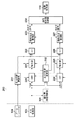
以下、図3のブロック図を用いて、本実施形態における、画像変形量演算部200の各構成部とその一例の動作について具体的に説明する。なお、本実施形態においては、画像変形部110で行う画像変形の各変形成分のうち、あおり、せん断、拡大縮小の成分は図3の構成には図示しないが、(式17)乃至(式21)あるいは(式25)乃至(式29)に従って各変形を行う構成にしてもよい。
Hereinafter, the components of the image deformation
図3のブロック図において、符号201から204までのブロックは、並進方向の像振れ(画像の水平垂直方向の像振れ)を補正するための補正量を算出するためのブロックである。符号211から213までのブロックは画像の回転を補正するための補正量を算出するためのブロックである。
In the block diagram of FIG. 3, blocks 201 to 204 are blocks for calculating a correction amount for correcting translational image blur (image blur in the horizontal and vertical directions of the image).
まず、並進ブレの補正量を算出するための符号201から204までのブロックについて説明する。HPF(ハイパスフィルタ)201には、前述したA/D変換器103からの出力のうち、YAW方向またはPITCH方向の角速度データが供給される。HPF201は、任意の周波数帯域でその特性を変更し得る機能を有しており、角速度データに含まれる低周波数成分を遮断して高周波数帯域の信号を出力する。
First, blocks 201 to 204 for calculating the translation blur correction amount will be described. Among the outputs from the A /
積分器202は、任意の周波数帯域でその特性を変更し得る機能を有しており、HPF201からの出力を積分し、焦点距離乗算部203に供給する。焦点距離演算部231は、前述したズームエンコーダ104の出力から、撮像光学系106の焦点距離を算出し、焦点距離乗算部203の演算に用いる焦点距離を算出する。焦点距離乗算部203は、積分器202の出力に、焦点距離演算部231によって算出された焦点距離fを乗算して、飽和防止制御部204に供給する。
The
飽和防止制御部204は、焦点距離乗算部203からの出力が所定値(以下、リミッタとする)以上とならないように、焦点距離乗算部203からの出力をリミットする制御を行う。また、飽和防止制御部204は、焦点距離乗算部203からの出力がリミッタに近づいたときに、HPF201のカットオフ周波数を高域側に変更したり、積分器202の時定数を短くする等の制御を行う。飽和防止制御部204の出力は、最終的な並進補正量(並進補正量演算)となり、画像変形量合成部230に供給される。
The saturation
次に、回転振れの補正量を算出する(回転補正量演算)ための符号211から213までのブロックについて説明する。HPF211には、前述したA/D変換器103からの出力のうち、ROLL方向の角速度データが供給される。HPF211は、任意の周波数帯域でその特性を変更し得る機能を有しており、角速度データに含まれる低周波数成分を遮断して高周波数帯域の信号を出力する。
Next, blocks 211 to 213 for calculating a rotational shake correction amount (rotational correction amount calculation) will be described. Among the outputs from the A /
積分器212は、任意の周波数帯域でその特性を変更し得る機能を有しており、HPF211からの出力を積分し、飽和防止制御部213に供給する。飽和防止制御部213は、積分器212からの出力が所定のリミッタ以上とならないように、積分器212からの出力をリミットする制御を行う。また、飽和防止制御部213は、積分器212からの出力がリミッタに近づいたときに、HPF211のカットオフ周波数を高域側に変更したり、積分器212の時定数を短くしたりする等の制御を行う。飽和防止制御部213の出力は、最終的な回転補正量となり、画像変形量合成部230に供給される。
The
画像変形量合成部230は、飽和防止制御部204、213から出力された、並進、回転、その他図示しないあおり等の補正量を合成する演算を行う。具体的には(式13)に従って、(式1)の射影変換行列を算出する。画像変形量合成部230は、算出した射影変換行列の各要素の値を、画像変形部110へと出力する。画像変形部110では、画像変形量合成部230からの出力に基づいて、画像変形による像振れ補正が行われる。
The image deformation
図4(a)、4(b)、4(c)は、画像変形部110における回転の補正について説明するための図である。図4(a)は、撮像装置に振れが生じていないときの撮像画像を示している。図4(b)は、撮像装置にROLL方向の振れが生じたときの撮像画像を示しており、画像変形部110では、画像変形量合成部230からの出力に基づいて、図4(b)の点線部のように画像メモリ109からの画像読み出し範囲を回転させる。図4(c)は、図4(b)の点線部のように画像読み出し範囲を回転させて出力した出力画像を示しており、図4(b)で傾いて撮像されていた被写体が元の形状に補正されている。ROLL方向の振れが正しく検出された場合は、図4(c)に示すように画像の回転補正を行うことができる。
4A, 4B, and 4C are diagrams for explaining the rotation correction in the
回転制御変更部300は、A/D変換器103のYAW方向あるいはPITCH方向の出力に基づいて、HPF211、積分器212、飽和防止制御部213の制御を変更する。以下、図5、図6を用いて、回転制御変更部300の処理について説明する。
The rotation
図5のフローチャートは、回転制御変更部300の処理の一例を示したものである。図5のフローチャートの処理は、例えば60Hz等の所定の周期で繰り返し実行される。
The flowchart of FIG. 5 shows an example of processing of the rotation
まず、S100では、変数SENSOR_OUT1を、A/D変換器103のYAW方向あるいはPITCH方向の出力に基づいて生成された信号とすると、SENSOR_OUT1が閾値AMP_TH1より大きいかどうかの判定を行う。A/D変換器103のYAW方向あるいはPITCH方向の出力に基づいて生成された信号とは、A/D変換器103の出力そのものであってもよいし、A/D変換器103の出力に対して、種々のフィルタリング処理を行ったり、ゲイン等をかけた信号であってもよい。すなわちA/D変換器103の出力を元に生成された信号であれば、どのような信号を用いてもよい。S100でSENSOR_OUT1がAMP_TH1より大きいと判定された場合は、S101の処理へと進む。
First, in S100, if the variable SENSOR_OUT1 is a signal generated based on the output of the A /
S101では、カウンタCOUNTER1の値をインクリメントし、S102の処理に進む。S102では、カウンタCOUNTER1が閾値TIME_TH1より大きいかどうかの判定を行う。S102でCOUNTER1がTIME_TH1以下であると判定された場合は、図5の処理は終了となる。S102でCOUNTER1がTIME_TH1より大きいと判定された場合は、S103の処理に進む。S103の処理が行われるのは、YAW方向或いはPITCH方向に所定時間(TIME_TH1)以上、所定の大きさ(AMP_TH1)以上の振れが加えられたとき、即ち、撮像装置100にパンニング或いはチルティング操作が行われた状態のときとなる。
In S101, the value of the counter COUNTER1 is incremented, and the process proceeds to S102. In S102, it is determined whether or not the counter COUNTER1 is larger than the threshold TIME_TH1. If it is determined in S102 that COUNTER1 is equal to or less than TIME_TH1, the processing in FIG. 5 ends. If it is determined in S102 that COUNTER1 is greater than TIME_TH1, the process proceeds to S103. The process of S103 is performed when a shake of a predetermined time (TIME_TH1) or more and a predetermined magnitude (AMP_TH1) or more is applied in the YAW direction or PITCH direction, that is, the panning or tilting operation is performed on the
S103では、回転補正量(ROLL方向の補正量)が小さくなるように制御する。HPF211のカットオフ周波数を高くする、積分器212の時定数を短くする、および飽和防止制御部213のリミッタを狭くする等の制御を行うことにより、回転補正量を制限するなどの制御を行う。なお、上記HPF211、積分器212、飽和防止制御部213の3種類の制御は、いずれか1種類のみ行うようにしてもよいし、複数種類の制御を組み合わせて行うようにしてもよい。また、上記3種類の制御に限らず、回転補正量が小さくなるように制御する方法であれば、他の方法を用いてもよい。例えば、回転の補正量がゼロに近づくような信号を、強制的に入力するような構成にしてもよい。また、飽和防止制御部213への入力値がある閾値を超えたときに、HPF211のカットオフ周波数を高くし、積分器212の時定数を短くする構成とし、当該閾値を小さくすることにより、回転補正量を制限するようにしてもよい。S103の処理の後、図5の処理は終了となる。 S100において、SENSOR_OUT1がAMP_TH1以下であると判定された場合は、S104の処理へと進む。S104では、S101でインクリメントするカウンタCOUNTER1の値をクリアし、S105に進む。
In S103, the rotation correction amount (correction amount in the ROLL direction) is controlled to be small. Controls such as limiting the rotation correction amount are performed by increasing the cut-off frequency of the
S105では、S103で変更したHPF211のカットオフ周波数、又は積分器212の時定数、又は飽和防止制御部213のリミッタを元に戻す処理を行う。また、その他回転の補正量を制限するための制御を行った場合はそれを解除する。S105の後、図5の処理は終了となる。
In S105, processing is performed to restore the cutoff frequency of the
図6は、回転制御変更部300が図5の処理を行ったときの、回転補正量の演算に与える効果を説明するためのグラフである。図6は、時間0からT0の期間、固定被写体(動きのない被写体)の撮影が行われ、次に時間T0からT2までパンニング等の大きな動きが撮像装置に加わる撮影が行われ、その後また固定被写体の撮影に戻ったときの各種信号の変化を示している。
FIG. 6 is a graph for explaining the effect on the calculation of the rotation correction amount when the rotation
図6(a)は、上記A/D変換器103のYAW方向あるいはPITCH方向の出力に基づいて生成された信号であるSENSOR_OUT1の、時間による変化を示したグラフである。SENSOR_OUT1は、撮像装置に大きな動きが加えられる時間帯であるT0からT2の間に出力が大きくなり、それ以外の時間ではYAW方向あるいはPITCH方向の手振れが検出されている様子を示している。
FIG. 6A is a graph showing a change over time of SENSOR_OUT1, which is a signal generated based on the output of the A /
図6(b)は、A/D変換器103のROLL方向の出力をSENSOR_OUT2として、SENSOR_OUT2の時間による変化を示したグラフである。図6(b)は、YAW方向あるいはPITCH方向に対して撮像装置に大きな動きが加えられる時間T0からT2の間に、ROLL方向への動きが発生していないにもかかわらず、角速度センサの検出軸のズレがあった場合にそのずれによって、出力が生じている様子を示している。T0からT2以外の時間ではROLL方向の手振れのみが検出されている。
FIG. 6B is a graph showing a change of SENSOR_OUT2 with time, assuming that the output in the ROLL direction of the A /
図6(c)は、回転制御変更部300による、図5のフローチャートの処理が行われなかったと仮定したときの飽和防止制御部213の出力信号をCALC_OUT1として、CALC_OUT1の時間による変化を示したグラフである。図6(c)は、図6(b)のグラフにおいて、時間T0からT2の間に角速度センサの検出軸のズレによって発生した出力が、HPF211及び積分器212の時定数によって減衰しきれずに、積分されてる様子を示している。
FIG. 6C is a graph showing the change of CALC_OUT1 over time, assuming that the output signal of the saturation
図4(d)(e)は、図6(c)の信号に基づいて、画像変形部110で回転の補正を行ったと仮定したときの画像について説明するための図である。図4(d)では、撮像装置にROLL方向の振れが生じていないにも関わらず、撮像画像に対して、図6(c)の信号に基づいて図4(d)の点線部のように画像メモリ109からの画像読み出し範囲を回転させている。図4(e)は、図4(d)の点線部のように画像読み出し範囲を回転させて出力した出力画像を示しており、図4(d)で傾いていなかった被写体が傾いて出力されている。
FIGS. 4D and 4E are diagrams for explaining an image when it is assumed that the rotation is corrected by the
図6(d)は、回転制御変更部300による、図5のフローチャートの処理が行われたときの飽和防止制御部213の出力信号をCALC_OUT2として、CALC_OUT2の時間による変化を示したグラフである。図6(a)において、図5のS100の判定がYesになるのは、SENSOR_OUT1の値がAMP_TH1よりも大きくなる、時間T0のタイミングである。更に、S102の判定がYesになるのは、COUNTER1がTIME_TH1よりも大きくなる、時間T1のタイミングとなる。よって、S103の処理は、時間T1から、S100の判定がNoに変わる時間T2までの期間に実行される。S103の処理において、HPF211のカットオフ周波数を高くすると、低周波数帯域の減衰率が大きくなるため、図6(b)の検出軸のズレによって発生した出力を減衰することができる。また、積分器212の時定数を短くすると、積分器212の出力がゼロに収束する速度が速くなるので、図6(b)の検出軸のズレによって発生した出力を減衰することができる。飽和防止制御部213のリミッタを狭くすると、積分器212の出力がリミッタに到達する時間が速くなり、HPF211のカットオフ周波数が高くなりやすく、積分器212の時定数が短くなりやすくなる。その結果、図6(b)の検出軸のズレによって発生した出力を減衰することができる。これによって、図6(c)で時間T0から大きくなり続けていた飽和防止制御部213の出力を、図6(d)に示すように減衰することができる。そして、図6(d)の信号に基づいて画像変形部110で回転の補正を行うことにより、図4(e)のように、撮像装置がROLL方向に動いていないのにも関わらず、撮像画像の回転補正を行ってしまう現象を防止することができる。
FIG. 6D is a graph showing the change of CALC_OUT2 with time, assuming that the output signal of the saturation
以上説明してきたように、本発明の第1の実施形態においては、撮像装置100に対してYAWあるいはPITCH方向にパンニング等の大きな動きが発生した場合、ROLL方向の角速度センサの出力に基づいた補正量の演算を制限することとした。これによって、角速度センサの検出軸のズレによって発生するROLL方向の信号の影響を最小限に抑え、良好な像振れ補正効果を得ることができる。
As described above, in the first embodiment of the present invention, when a large movement such as panning occurs in the YAW or PITCH direction with respect to the
なお、本実施形態においては、回転の補正方法として、画像変形によるものを例にとって説明したが、撮像素子を機械的に回転する方法を用いてもよい。 In the present embodiment, the rotation correction method has been described by taking the image deformation as an example. However, a method of mechanically rotating the image sensor may be used.
(第2の実施形態)
本発明の第2の実施形態に係る撮像装置について、以下に説明する。本実施形態において、撮像装置の構成は図1と同様であり、画像変形量演算部200の内部構成が異なるものであるため、図1の説明は省略する。また、本実施形態における画像変形量演算部200が、第1の実施形態と異なる点は、図3に示した第1の実施形態の構成に、図3に破線で示した撮影者移動判定部301が追加されている点である。
(Second Embodiment)
An imaging apparatus according to the second embodiment of the present invention will be described below. In the present embodiment, the configuration of the imaging apparatus is the same as that in FIG. 1, and the internal configuration of the image deformation
撮影者移動判定部301は、A/D変換器103のYAW方向あるいはPITCH方向あるいはROLL方向の出力に基づいて生成された信号から、撮像装置100が撮影者が歩く等の移動をしながら撮影を行っているかどうかの判定を行う。撮影者移動判定部301は、撮影者が移動しながら撮影を行っていると判定したとき、回転制御変更部300で行われる処理の変更を行う。
The photographer
図7のフローチャートは、撮影者移動判定部301の処理の一例を示したものである。図7のフローチャートの処理は、例えば60Hz等の所定の周期で繰り返し実行される。
The flowchart in FIG. 7 shows an example of processing of the photographer
図7の処理の概要としては、A/D変換器103の出力に基づいて生成された信号が、所定期間中に所定の振幅を超えてプラス方向とマイナス方向に所定回数振れたときに、撮影者が移動していると判定し、回転制御変更部300の処理を変更するものである。言い換えると、撮影者移動判定部301は、角速度センサ102の出力に基づいた信号の変化が、予め定めた周波数及び振幅より大きいと判定されたときに、撮影者が移動していると判定し、回転制御変更部300の処理を変更する。以下、図7の処理について説明する。
As an overview of the processing in FIG. 7, the image generated when the signal generated based on the output of the A /
まず、S200では、カウンタCOUNTER2の値をインクリメントし、S201の処理に進む。S201では、フラグSIGN_FLAGが0かどうかの判定を行う。S201で、SIGN_FLAGが0のときはS202の処理に進み、SIGN_FLAGが1のときはS206の処理に進む。 First, in S200, the value of the counter COUNTER2 is incremented, and the process proceeds to S201. In S201, it is determined whether or not the flag SIGN_FLAG is 0. In S201, when SIGN_FLAG is 0, the process proceeds to S202, and when SIGN_FLAG is 1, the process proceeds to S206.
S202では、変数SENSOR_OUT3を、A/D変換器103のYAW方向あるいはPITCH方向あるいはROLL方向の出力に基づいて生成された信号とすると、SENSOR_OUT3が閾値AMP_TH2より大きいかどうかの判定を行う。A/D変換器103のYAW方向あるいはPITCH方向あるいはROLL方向の出力に基づいて生成された信号とは、A/D変換器103の出力そのものであってもよいし、A/D変換器103の出力に対して、種々のフィルタリング処理を行ったり、ゲイン等をかけた信号であってもよい。すなわち、A/D変換器103の出力を元に生成された信号であれば、どのような信号を用いてもよい。S202でSENSOR_OUT3がAMP_TH2より大きいと判定された場合は、S203の処理に進み、SENSOR_OUT3がAMP_TH2以下であると判定された場合は、S210の処理に進む。
In S202, if the variable SENSOR_OUT3 is a signal generated based on the output of the A /
S203では、上記SENSOR_OUT2の振幅が、閾値AMP_TH2を超えた回数をカウントするための変数OVER_COUNTをインクリメントし、S204に進む。S204ではフラグSIGN_FLAGの値を1に変更し、次に図7の処理が行われるときは、S201でNoと判定されるようにする。S205ではS200でインクリメントしたカウンタCOUNTER2の値をクリアし、S210の処理に移る。 In S203, the variable OVER_COUNT for counting the number of times that the amplitude of SENSOR_OUT2 exceeds the threshold AMP_TH2 is incremented, and the process proceeds to S204. In S204, the value of the flag SIGN_FLAG is changed to 1, and when the processing of FIG. 7 is performed next, it is determined as No in S201. In S205, the value of the counter COUNTER2 incremented in S200 is cleared, and the process proceeds to S210.
S206では、上記SENSOR_OUT3が閾値(0−AMP_TH2)より小さいかどうかの判定を行う。S206でSENSOR_OUT3が(0−AMP_TH2)より小さいと判定された場合は、S207の処理に進み、SENSOR_OUT3が(0−AMP_TH2)以上であると判定された場合は、S210の処理に進む。 In S206, it is determined whether or not the SENSOR_OUT3 is smaller than a threshold value (0-AMP_TH2). If it is determined in S206 that SENSOR_OUT3 is smaller than (0-AMP_TH2), the process proceeds to S207. If it is determined that SENSOR_OUT3 is equal to or greater than (0-AMP_TH2), the process proceeds to S210.
S207では、S203と同様に上記変数OVER_COUNTをインクリメントし、S208に進む。S208ではフラグSIGN_FLAGの値を0に変更し、次に図7の処理が行われるときは、S201で再びYesと判定されるようにする。S209は、S205と同様にS200でインクリメントしたカウンタCOUNTER2の値をクリアし、S210の処理に移る。 In S207, the variable OVER_COUNT is incremented as in S203, and the process proceeds to S208. In S208, the value of the flag SIGN_FLAG is changed to 0, and when the processing in FIG. 7 is performed next, it is determined again as Yes in S201. In S209, the value of the counter COUNTER2 incremented in S200 is cleared as in S205, and the process proceeds to S210.
S210では、S200でインクリメントしたカウンタCOUNTER2が、閾値TIME_TH2以上かどうかの判定を行う。S210で、COUNTER2がTIME_TH2以上であると判定された場合はS214に進み、COUNTER2がTIME_TH2より小さいと判定された場合はS211に進む。S211では、上記OVER_COUNTの値が閾値COUNT_TH以上かどうかの判定を行う。S211で、OVER_COUNTがCOUNT_TH以上の場合は、S212の処理に進み、OVER_COUNTの値がCOUNT_THより小さい場合は、S216の処理に進む。S212では、OVER_COUNTがオーバーフローしないように、OVER_COUNTの値をCOUNT_THにリミットし、S213の処理に進む。 In S210, it is determined whether or not the counter COUNTER2 incremented in S200 is greater than or equal to the threshold TIME_TH2. If it is determined in S210 that COUNTER2 is greater than or equal to TIME_TH2, the process proceeds to S214, and if it is determined that COUNTER2 is smaller than TIME_TH2, the process proceeds to S211. In S211, it is determined whether or not the value of OVER_COUNT is equal to or greater than a threshold value COUNT_TH. In S211, if OVER_COUNT is greater than or equal to COUNT_TH, the process proceeds to S212, and if the value of OVER_COUNT is smaller than COUNT_TH, the process proceeds to S216. In S212, the value of OVER_COUNT is limited to COUNT_TH so that OVER_COUNT does not overflow, and the process proceeds to S213.
S213の処理が行われる場合は、COUNTER2がTIME_TH2に達する前に、S203及びS207でOVER_COUNTの値がインクリメントされ、COUNT_THに達したときである。すなわち、SENSOR_OUT3の出力が、プラスマイナス方向にAMP_TH2より大きい振幅でOVER_COUNT回数以上振れたとき(所定期間内で閾値より大きい振幅で所定回数以上振れたとき)である。このとき、撮像装置は撮影者が移動しながら(たとえば歩きながら)撮影されているものと判断する。 The process of S213 is performed when the value of OVER_COUNT is incremented in S203 and S207 and reaches COUNT_TH before COUNTER2 reaches TIME_TH2. That is, when the output of SENSOR_OUT3 fluctuates more than OVER_COUNT times with an amplitude greater than AMP_TH2 in the plus or minus direction (when the output fluctuates more than a predetermined number of times with an amplitude greater than a threshold within a predetermined period). At this time, the imaging apparatus determines that the photographer is shooting while moving (for example, walking).
S213では、回転制御変更部300が行う図5のS103の処理を禁止又は限定する。S103の処理を禁止するとは、S103で行うHPF211のカットオフ周波数変更、積分器212の時定数変更、飽和防止制御部213のリミッタ変更を元に戻すことをいう。また、その他回転の補正量を制限するための制御を行っていた場合はそれを解除する。S103の処理を限定するとは、HPF211のカットオフ周波数を高くする量や、積分器212の時定数を短くする量、飽和防止制御213のリミッタを狭くする量を小さくすることをいう。また、例えばHPF211のカットオフ周波数変更と積分器212の時定数変更を行っていた場合に、一方の変更を行わないというように、S103における複数の回転補正量の制限のうち、いくつかを禁止するという構成にしてもよい。S213の後は、図7の処理は終了となる。
In S213, the process of S103 in FIG. 5 performed by the rotation
S214の処理が行われる場合は、COUNTER2がS205あるいはS209でクリアされずにTIME_TH2に達したときである。すなわち、SENSOR_OUT3の出力が、AMP_TH2以下の振幅で推移し続けたときである。このとき、撮像装置は撮影者が移動していない状態(立ち止まったり座っている状態)で撮影されているものと判断する。S214では、COUNTER2がオーバーフローしないように、COUNTER2の値をTIME_TH2にリミットし、S215の処理に進む。S215ではOVER_COUNTの値をクリアしS216に進む。 The process of S214 is performed when COUNTER2 reaches TIME_TH2 without being cleared in S205 or S209. That is, when the output of SENSOR_OUT3 continues to change with an amplitude of AMP_TH2 or less. At this time, the imaging apparatus determines that the photographer is photographing in a state where the photographer is not moving (a state where the photographer stops or sits down). In S214, the value of COUNTER2 is limited to TIME_TH2 so that COUNTER2 does not overflow, and the process proceeds to S215. In S215, the value of OVER_COUNT is cleared, and the process proceeds to S216.
S216の処理は、S214、S215を経由する場合、OVER_COUNTが、まだ撮影者が移動しながら撮影されているかどうかの判定のための閾値であるCOUNT_THに達していない場合に実行される。S216では、回転制御変更部300が行う図5のS103の処理の実行を許可する。すなわち、S213における、S103の処理を禁止又は限定する処理を解除し、回転制御変更部300が図5のフローチャートに従って動作する状態に戻す。S216の後は、図7の処理は終了となる。
The process of S216 is executed when OVER_COUNT has not reached COUNT_TH, which is a threshold value for determining whether or not the photographer is still moving while taking the image through S214 and S215. In S216, the execution of the process in S103 of FIG. 5 performed by the rotation
図8は、撮影者移動判定部301の処理を説明するためのグラフである。図8は、時間0からT10の期間、撮影者が静止した状態で固定被写体の撮影が行われ、時間T10から、撮影者が歩きながら撮影が行われたときの各種信号の変化を示している。
FIG. 8 is a graph for explaining the processing of the photographer
図8(a)は、上記A/D変換器103のYAW方向あるいはPITCH方向あるいはROLL方向の出力に基づいて生成された信号であるSENSOR_OUT3の、時間による変化を示したグラフである。SENSOR_OUT3は、T10から歩行時の振動により出力が大きくなり、T10より前の時間では比較的小さい静止時の手振れが検出されている様子を示している。
FIG. 8A is a graph showing a change over time of SENSOR_OUT3 which is a signal generated based on the output of the A /
図7のフローチャートにおいて、COUNT_TH=2とすると、SENSOR_OUT3の出力の大きさが、プラス方向とマイナス方向でAMP_TH2を超えたT11から、撮影者移動判定部301によって、撮影者が移動しながら撮影されているという判定が行われる。
In the flowchart of FIG. 7, when COUNT_TH = 2, the photographer
図8(b)は、A/D変換器103のROLL方向の出力をSENSOR_OUT2として、SENSOR_OUT2の時間による変化を示したグラフである。撮影者が移動して撮影を行う場合、角速度センサ102の出力は、YAW方向、PITCH方向、ROLL方向全てにおいて出力が大きくなる。よって、図5の処理において、S103の処理が行われる頻度が高くなる。第1の実施形態で説明したように、検出軸のズレによってSENSOR_OUT2に重畳される、YAW方向あるいはPITCH方向の振れによる出力成分が大きくなる影響を軽減するためである。
FIG. 8B is a graph showing a change of SENSOR_OUT2 with time, assuming that the output in the ROLL direction of the A /
しかし一方で、A/D変換器103のROLL方向の出力であるSENSOR_OUT2自体の信号も、図9(b)に示すように、撮影者が歩き始めるT10から大きくなる。その状態で、S103の処理に従って、画像の回転補正量を制限してしまうと、歩行時のROLL方向の振れの補正効果が弱くなり、却って見づらい映像となってしまう。そこで、撮影者移動判定部301によるS213の処理において、S103の処理の実行を禁止あるいは限定することによって、これを回避している。
However, on the other hand, the signal of SENSOR_OUT2 itself, which is the output in the ROLL direction of the A /
以上説明してきたように、本発明の第2の実施形態においては、撮像装置100に対してYAWあるいはPITCH方向にパンニング等の大きな動きが発生した場合、ROLL方向の角速度センサの出力に基づいた補正量の演算を制限する第1の実施形態に対し、更に以下の処理を追加した。すなわち、角速度センサの出力から、撮影者が歩く等の移動をしながら撮影が行われているかどうかの判定を行い、移動しながらの撮影という判定が行われているときは、ROLL方向に発生している振れの補正を優先して行うようにした。これによって、撮影者が移動する際の大きな振れによって発生する撮像画像の振れに対しても、良好な像振れ補正効果を得ることができる。
As described above, in the second embodiment of the present invention, when a large movement such as panning occurs in the YAW or PITCH direction with respect to the
なお、本第2の実施形態においては、回転の補正方法として、画像変形によるものを例にとって説明したが、撮像素子を機械的に回転する方法を用いてもよい。 In the second embodiment, the rotation correction method has been described by taking the image deformation as an example. However, a method of mechanically rotating the image sensor may be used.
(第3の実施形態)
本発明の第3の実施形態に係る撮像装置について、以下に説明する。本実施形態において、撮像装置の構成は図1と同様であり、画像変形量演算部200の内部構成が異なるものであるため、図1の説明は省略する。
(Third embodiment)
An imaging apparatus according to the third embodiment of the present invention will be described below. In the present embodiment, the configuration of the imaging apparatus is the same as that in FIG. 1, and the internal configuration of the image deformation
以下、図9のブロック図を用いて、本実施形態における、画像変形量演算部200の各構成部とその一例の動作について具体的に説明する。なお、図9において、図3と同様の構成には、同じ符号を付し、説明は省略する。また、本実施形態においては、画像変形部110で行う画像変形の各変形成分のうち、並進、回転、せん断、拡大縮小の成分は必須でないため、図10の構成には図示しないが、(式16)、(式19)乃至(式21)あるいは(式24)、(式27)乃至(式29)に従って各変形を行う構成にしてもよい。
Hereinafter, the components of the image deformation
図9のブロック図において、符号220から223までのブロックは、撮像装置へのYAW方向の振れによって生じる、水平方向のあおりを補正するための補正量を算出するためのブロック(あおり補正量演算部)である。符号224から227までのブロックは、撮像装置へのPITCH方向の振れによって生じる、垂直方向のあおりを補正するための補正量を算出するためのブロック(あおり補正量演算部)である。
In the block diagram of FIG. 9, blocks 220 to 223 are blocks for calculating a correction amount for correcting a horizontal tilt caused by a shake in the YAW direction to the imaging apparatus (a tilt correction amount calculation unit). ). Blocks denoted by
まず、水平方向のあおりの補正量を算出するための符号220から223までのブロックについて説明を行う。HPF220には、A/D変換器103からの出力のうち、YAW方向の角速度データが供給される。HPF220は、任意の周波数帯域でその特性を変更し得る(可変)機能を有しており、角速度データに含まれる低周波数成分を遮断して高周波数帯域の信号を出力する。
First, blocks 220 to 223 for calculating the horizontal tilt correction amount will be described. Among the outputs from the A /
積分器221は、任意の周波数帯域でその特性を変更し得る機能を有しており、HPF220からの出力を積分し、焦点距離除算部222に供給する。焦点距離除算部222は、積分器221の出力を、焦点距離演算部231によって算出された焦点距離fで除算して、飽和防止制御部223に供給する。積分器221の出力を焦点距離fで除算する理由は(式25)による。
The
飽和防止制御部223は、焦点距離除算部222からの出力(演算値)がリミッタ(限界値)以上とならないように、焦点距離除算部222からの出力をリミットする制御を行う。また、飽和防止制御部223は、焦点距離除算部222からの出力がリミッタに近づいたときに、HPF220のカットオフ周波数を高域側に変更したり、積分器221の時定数を短くする等の制御を行う。飽和防止制御部223の出力は、最終的な水平方向のあおり補正量となり、画像変形量合成部230に供給される。
The saturation
次に、垂直方向のあおりの補正量を算出するための符号224から227までのブロックについて説明を行う。HPF224には、A/D変換器103からの出力のうち、PITCH方向の角速度データが供給される。HPF224は、任意の周波数帯域でその特性を変更し得る機能を有しており、角速度データに含まれる低周波数成分を遮断して高周波数帯域の信号を出力する。
Next, blocks 224 to 227 for calculating the tilt correction amount in the vertical direction will be described. Among the outputs from the A /
積分器225は、任意の周波数帯域でその特性を変更し得る機能を有しており、HPF224からの出力を積分し、焦点距離除算部226に供給する。焦点距離除算部226は、積分器225の出力を、焦点距離演算部231によって算出された焦点距離fで除算して、飽和防止制御部227に供給する。積分器225の出力を焦点距離fで除算する理由は(式26)による。
The
飽和防止制御部227は、焦点距離除算部226からの出力がリミッタ以上とならないように、焦点距離除算部226からの出力をリミットする制御を行う。また、飽和防止制御部227は、焦点距離除算部226からの出力がリミッタに近づいたときに、HPF224のカットオフ周波数を高域側に変更したり、積分器225の時定数を短くする等の制御を行う。飽和防止制御部227の出力は、最終的な垂直方向のあおり補正量となり、画像変形量合成部230に供給される。
The saturation
画像変形量合成部230は、飽和防止制御部223、227から出力された、水平および垂直方向のあおり、その他図示しない並進、回転等の補正量を合成する演算を行う。具体的には(式13)に従って、(式1)の射影変換行列を算出する。画像変形量合成部230は、算出した射影変換行列の各要素の値を、画像変形部110へと出力する。画像変形部110では、画像変形量合成部230からの出力に基づいて、画像変形による像振れ補正が行われる。
The image deformation
図10(a)、10(b)、10(c)は、画像変形部110における幾何変換処理による垂直方向のあおりの補正について説明するための図である。図10(a)は、撮像装置に振れが生じていないときの撮像画像を示している。図10(b)は、撮像装置にPITCH方向の振れが生じ、垂直方向のあおりの変形が生じたときの撮像画像を示している。画像変形部110では、画像変形量合成部230からの出力に基づいて、図10(b)の点線部のように画像メモリ109からの画像読み出し範囲を台形状の範囲とする。図10(c)は、図10(b)の点線部のように画像読み出し範囲を台形状として出力した出力画像を示しており、図10(b)で台形状に歪んで撮像されていた被写体が元の形状に補正されている。角速度センサ102により振れが正しく検出された場合は、図10(c)に示すように画像のあおり補正を行うことができる。
FIGS. 10A, 10B, and 10C are diagrams for explaining correction of vertical tilt by the geometric transformation processing in the
あおり制御変更部302は、A/D変換器103のYAW方向あるいはPITCH方向の出力に基づいて、HPF220、積分器221、飽和防止制御部223、HPF224、積分器225、飽和防止制御部227の制御を変更する。以下、図5、図6を用いて、あおり制御変更部302の処理について説明する。なお、図5、図6は、第1の実施形態においては、回転制御変更部300の処理として説明を行ったが、回転制御変更部300とあおり制御変更部302では、処理する信号が異なり、処理のステップは同様である。よって、本実施形態においては、図5、図6を、あおり制御変更部302が行う処理として説明する。また、以下の説明においては、YAW方向の振れ信号に基づいて、PITCH方向の振れ信号に対する処理を変更する場合について説明を行う。なお、PITCH方向の振れ信号に基づいて、YAW方向の振れ信号に対する処理を変更する場合は、同様であるため説明は省略する。
The tilt
図5のフローチャートは、あおり制御変更部302の処理の一例を示したものである。図5のフローチャートの処理は、例えば60Hz等の所定の周期で繰り返し実行される。
The flowchart of FIG. 5 shows an example of processing of the tilt
まず、S100では、変数SENSOR_OUT1を、A/D変換器103のYAW方向の出力に基づいて生成された信号とすると、SENSOR_OUT1が閾値AMP_TH1より大きいかどうかの判定を行う。A/D変換器103のYAW方向の出力に基づいて生成された信号とは、A/D変換器103の出力そのものであってもよいし、A/D変換器103の出力に対して、種々のフィルタリング処理を行ったり、ゲイン等をかけた信号であってもよい。すなわちA/D変換器103の出力を元に生成された信号であれば、どのような信号を用いてもよい。S100でSENSOR_OUT1がAMP_TH1より大きいと判定された場合は、S101の処理へと進む。
First, in S100, if the variable SENSOR_OUT1 is a signal generated based on the output of the A /
S101では、カウンタCOUNTER1の値をインクリメントし、S102の処理に進む。S102では、カウンタCOUNTER1が閾値TIME_TH1より大きいかどうかの判定を行う。S102でCOUNTER1がTIME_TH1以下であると判定された場合は、図5の処理は終了となる。S102でCOUNTER1がTIME_TH1より大きいと判定された場合は、S103の処理に進む。S103の処理が行われるのは、YAW方向に所定時間(TIME_TH1)以上、所定の大きさ(AMP_TH1)以上の振れが加えられたとき(振れが所定の閾値より大きい時間が、所定時間以上継続したとき)、即ち、撮像装置100にパンニング操作が行われた状態のときとなる。
In S101, the value of the counter COUNTER1 is incremented, and the process proceeds to S102. In S102, it is determined whether or not the counter COUNTER1 is larger than the threshold TIME_TH1. If it is determined in S102 that COUNTER1 is equal to or less than TIME_TH1, the processing in FIG. 5 ends. If it is determined in S102 that COUNTER1 is greater than TIME_TH1, the process proceeds to S103. The process of S103 is performed when a shake for a predetermined time (TIME_TH1) or more and a predetermined magnitude (AMP_TH1) or more is applied in the YAW direction (the time when the shake is greater than a predetermined threshold continues for a predetermined time or more) That is, when the panning operation is performed on the
S103では、あおりの補正量が小さくなるように制御する。HPF(高域通過フィルタ)224のカットオフ周波数(遮断周波数)を高くする、積分器225の時定数を短くする、飽和防止制御部227のリミッタを狭くする等の制御を行う。なお、上記HPF224、積分器225、飽和防止制御部227の3種類の制御は、いずれか1種類のみ行うようにしてもよいし、複数種類の制御を組み合わせて行うようにしてもよい。また、上記3種類の制御に限らず、あおりの補正量が小さくなるように制御する方法であれば、他の方法を用いてもよい。例えば、あおりの補正量がゼロに近づくような信号を、強制的に入力するような構成にしてもよい。また、飽和防止制御部227への入力値がある閾値を超えたときに、HPF224のカットオフ周波数を高くし、積分器225の時定数を短くする構成とし、当該閾値を小さくすることにより、あおりの補正量を制限するようにしてもよい。S103の処理の後、図5の処理は終了となる。
In step S103, control is performed so that the tilt correction amount is reduced. Control is performed such as increasing the cutoff frequency (cutoff frequency) of the HPF (high pass filter) 224, shortening the time constant of the
S100において、SENSOR_OUT1がAMP_TH1以下であると判定された場合は、S104の処理へと進む。S104では、S101でインクリメントするカウンタCOUNTER1の値をクリアし、S105に進む。 If it is determined in S100 that SENSOR_OUT1 is equal to or less than AMP_TH1, the process proceeds to S104. In S104, the value of the counter COUNTER1 incremented in S101 is cleared, and the process proceeds to S105.
S105では、S103で変更したHPF224のカットオフ周波数、又は積分器225の時定数、又は飽和防止制御部227のリミッタを元に戻す処理を行う。また、その他回転の補正量を制限するための制御を行った場合はそれを解除する。S105の後、図5の処理は終了となる。
In S105, processing is performed to restore the cutoff frequency of the
図6は、あおり制御変更部302が図5の処理を行ったときの、垂直方向のあおり補正量の演算に与える効果を説明するためのグラフである。図6は、時間0からT0の期間、固定被写体の撮影が行われ、次に時間T0からT2までパンニング等の大きな動きが撮像装置に加わる撮影が行われ、その後また固定被写体の撮影に戻ったときの各種信号の変化を示している。
FIG. 6 is a graph for explaining the effect of the tilt
図6(a)は、上記A/D変換器103のYAW方向の出力に基づいて生成された信号であるSENSOR_OUT1の、時間による変化を示したグラフである。SENSOR_OUT1は、撮像装置に大きな動きが加えられる時間帯であるT0からT2の間に出力が大きくなり、それ以外の時間ではYAW方向の手振れが検出されている様子を示している。
FIG. 6A is a graph showing a change with time of SENSOR_OUT1, which is a signal generated based on the output of the A /
図6(b)は、A/D変換器103のPITCH方向の出力をSENSOR_OUT2として、SENSOR_OUT2の時間による変化を示したグラフである。図6(b)は、YAW方向に対して撮像装置に大きな動きが加えられる時間T0からT2の間に、PITCH方向への動きが発生していないにもかかわらず、角速度センサの検出軸のズレによって、出力が生じている様子を示している。T0からT2以外の時間ではPITCH方向の手振れが検出されている。
FIG. 6B is a graph showing changes in SENSOR_OUT2 with time, assuming that the output of the A /
図6(c)は、あおり制御変更部302による、図5のフローチャートの処理が行われなかったと仮定したときの飽和防止制御部227の出力信号をCALC_OUT1として、CALC_OUT1の時間による変化を示したグラフである。図6(c)は、図6(b)のグラフにおいて、時間T0からT2の間に角速度センサの検出軸のズレによって発生した出力が、HPF224及び積分器225の時定数によって減衰しきれずに、積分されている様子を示している。
FIG. 6C is a graph showing the change of CALC_OUT1 over time, assuming that the output signal of the saturation
図10(d)、10(e)は、図6(c)の信号に基づいて、画像変形部110で垂直方向のあおりの補正を行ったと仮定したときの画像について説明するための図である。図10(d)では、撮像装置にPITCH方向の振れが生じていないにも関わらず、撮像画像に対して、図6(c)の信号に基づいて図10(d)の点線部のように画像メモリ109からの画像読み出し範囲を台形状に変更している。図10(e)は、図10(d)の点線部のように画像読み出し範囲を台形状に変更させて出力した出力画像を示しており、図10(d)で台形状に変形していなかった被写体が台形状に変形して出力されている。
FIGS. 10D and 10E are diagrams for explaining an image when it is assumed that correction of vertical tilt is performed by the
図6(d)は、あおり制御変更部302による、図5のフローチャートの処理が行われたときの飽和防止制御部227の出力信号をCALC_OUT2として、CALC_OUT2の時間による変化を示したグラフである。図6(a)において、図5のS100の判定がYesになるのは、SENSOR_OUT1の値がAMP_TH1よりも大きくなる、時間T0のタイミングである。更に、S102の判定がYesになるのは、COUNTER1がTIME_TH1よりも大きくなる、時間T1のタイミングとなる。よって、S103の処理は、時間T1から、S100の判定がNoに変わる時間T2までの期間に実行される。S103の処理において、HPF224のカットオフ周波数を高くすると、低周波数帯域の減衰率が大きくなるため、図6(b)の検出軸のズレによって発生した出力を減衰することができる。また、積分器225の時定数を短くすると、積分器225の出力がゼロに収束する速度が速くなるので、図6(b)の検出軸のズレによって発生した出力を減衰することができる。飽和防止制御部227のリミッタを狭くすると、積分器225の出力がリミッタに到達する時間が速くなり、HPF224のカットオフ周波数が高くなりやすく、積分器225の時定数が短くなりやすくなる。その結果、図6(b)の検出軸のズレによって発生した出力を減衰することができる。これによって、図6(c)で時間T0から大きくなり続けていた飽和防止制御部227の出力を、図6(d)に示すように減衰することができる。そして、図6(d)の信号に基づいて画像変形部110であおりの補正を行うことにより、図10(e)のように、撮像装置がPITCH方向に動いていないのにも関わらず、撮像画像の垂直方向のあおりの補正を行ってしまう現象を防止することができる。
FIG. 6D is a graph showing the change of CALC_OUT2 with time, assuming that the output signal of the saturation
なお上述したように、あおり制御変更部302は、PITCH方向の振れ信号に基づいて、水平方向のあおりの補正量算出の処理を変更する制御も行うが、上記説明においてYAW方向とPICH方向を入れ替えれば同様の処理となるため、説明は省略する。
As described above, the tilt
以上説明してきたように、本発明の第3の実施形態においては、撮像装置100に対してYAW方向にパンニング等の大きな動きが発生した場合、PITCH方向の角速度センサの出力に基づいたあおりの補正量の演算を制限することとした。また、撮像装置100に対してPITCH方向にチルティング等の大きな動きが発生した場合、YAW方向の角速度センサの出力に基づいたあおりの補正量の演算を制限することとした。これによって、角速度センサの検出軸のズレによって発生する信号の誤差の影響を最小限に抑え、良好な像振れ補正効果を得ることができる。
As described above, in the third embodiment of the present invention, when a large movement such as panning occurs in the YAW direction with respect to the
(第4の実施形態)
本発明の第4の実施形態に係る撮像装置について、以下に説明する。本実施形態において、撮像装置の構成は図1と同様であり、画像変形量演算部200の内部構成が異なるものであるため、図1の説明は省略する。また、本実施形態における画像変形量演算部200は、図9にも示した第3の実施形態の構成と類似しており、第3の実施形態と異なる点は、第3の実施形態の構成に、図9に破線で示した撮影者移動判定部301が追加されている点である。
(Fourth embodiment)
An imaging apparatus according to the fourth embodiment of the present invention will be described below. In the present embodiment, the configuration of the imaging apparatus is the same as that in FIG. 1, and the internal configuration of the image deformation
撮影者移動判定部301は、A/D変換器103のYAW方向あるいはPITCH方向あるいはROLL方向の出力に基づいて生成された信号から、撮像装置100が撮影者が歩く等の移動をしながら撮影を行っているかどうかの判定を行う。撮影者移動判定部301は、撮影者が移動しながら撮影を行っていると判定したとき、あおり制御変更部302で行われる処理の変更を行う。撮影者移動判定部301の処理は、第2の実施形態において、図7のフローチャートで説明したものと、S213及びS216の処理以外は同様であるため、S213及びS216の処理以外の詳細な説明は省略する。
The photographer
S213では、あおり制御変更部302が行う図5のS103の処理を禁止又は限定する。S103の処理を禁止するとは、S103で行うHPF220あるいはHPF224のカットオフ周波数変更、積分器221あるいは積分器225の時定数変更、飽和防止制御部223あるいは飽和防止制御部227のリミッタ変更を元に戻すことをいう。また、その他あおりの補正量を制限するための制御を行っていた場合はそれを解除する。S103の処理を限定するとは、HPF220あるいはHPF224のカットオフ周波数を高くする量や、積分器221あるいは積分器225の時定数を短くする量、飽和防止制御部223あるいは飽和防止制御部227のリミッタを狭くする量を小さくすることをいう。また、例えばHPF220あるいはHPF224のカットオフ周波数変更と、積分器221あるいは積分器225の時定数変更を行っていた場合に、一方の変更を行わない、というように、S103における複数のあおり補正量の制限のうち、いくつかのあおり補正量の制限を禁止するという構成にしてもよい。
In S213, the process of S103 in FIG. 5 performed by the tilt
S216では、あおり制御変更部302が行う図5のS103の処理の実行を許可する。すなわち、S213における、S103の処理を禁止又は限定する処理を解除し、あおり制御変更部302が図5のフローチャートに従って動作する状態に戻す。S216の後は、図7の処理は終了となる。
In S216, the execution of the process of S103 in FIG. 5 performed by the tilt
次に図8を用いて、撮影者が歩きながら撮影を行ったときの、撮影者移動判定部301の処理について説明する。上記第2の実施形態において、図8(b)のSENSOR_OUT2は、A/D変換器103のROLL方向の出力であるとして説明を行ったが、本実施形態においては、A/D変換器103のYAW方向あるいはPITCH方向の出力として説明を行う。図9は、上述したように、時間0からT10の期間、撮影者が静止した状態で固定被写体の撮影が行われ、時間T10から、撮影者が歩きながら撮影が行われたときの各種信号の変化を示している。
Next, the processing of the photographer
図8(a)は、上記A/D変換器103のYAW方向あるいはPITCH方向あるいはROLL方向の出力に基づいて生成された信号であるSENSOR_OUT3の、時間による変化を示したグラフである。SENSOR_OUT3は、T10から歩行時の振動により出力が大きくなり、T10より前の時間では比較的小さい静止時の手振れが検出されている様子を示している。
FIG. 8A is a graph showing a change over time of SENSOR_OUT3 which is a signal generated based on the output of the A /
図7のフローチャートにおいて、COUNT_TH=2とすると、SENSOR_OUT3の出力の大きさが、プラス方向とマイナス方向でAMP_TH2を超えたT11から、撮影者移動判定部301によって、撮影者が移動しながら撮影されているという判定が行われる。
In the flowchart of FIG. 7, when COUNT_TH = 2, the photographer
図8(b)は、A/D変換器103のYAW方向あるいはPITCH方向の出力をSENSOR_OUT2として、SENSOR_OUT2の時間による変化を示したグラフである。撮影者が移動して撮影を行う場合、角速度センサ102の出力は、YAW方向、PITCH方向、ROLL方向全てにおいて出力が大きくなる。よって、図5の処理において、S103の処理が行われる頻度が高くなる。第2の実施形態で説明したように、検出軸のズレによってSENSOR_OUT2に重畳される、他軸方向の振れによる出力成分が大きくなる影響を軽減するためである。
FIG. 8B is a graph showing changes in SENSOR_OUT2 with time, assuming that the output of the A /
しかし一方で、A/D変換器103のYAW方向自体の出力あるいはPITCH方向自体の出力であるSENSOR_OUT2も、図8(b)に示すように、撮影者が歩き始めるT10から大きくなる。その状態で、S103の処理に従って、画像のあおりの補正量を制限してしまうと、歩行時のあおりの補正効果が弱くなり、却って見づらい映像となってしまう。そこで、撮影者移動判定部301によるS213の処理において、S103の処理の実行を禁止あるいは限定(緩和)することによって、これを回避している。
However, SENSOR_OUT2, which is the output of the A /
以上説明してきたように、本発明の第4の実施形態においては、撮像装置100に対してYAWあるいはPITCH方向にパンニング等の大きな動きが発生した場合、他方向の角速度センサの出力に基づいた補正量の演算を制限する第3の実施形態に対し、更に以下の処理を追加した。すなわち、角速度センサの出力から、撮影者が歩く等の移動をしながら撮影が行われているかどうかの判定を行い、移動しながらの撮影という判定が行われているときは、YAW方向あるいはPITCH方向に発生している振れの補正を優先して行うようにした。これによって、撮影者が移動する際の大きな振れによって発生する撮像画像の振れに対しても、良好なブレ補正効果を得ることができる。
As described above, in the fourth embodiment of the present invention, when a large movement such as panning occurs in the YAW or PITCH direction with respect to the
以上、本発明をその好適な実施形態に基づいて詳述してきたが、本発明はこれら特定の実施形態に限られるものではなく、この発明の要旨を逸脱しない範囲の様々な形態も本発明に含まれる。上述の実施形態の一部を適宜組み合わせてもよい。 Although the present invention has been described in detail based on preferred embodiments thereof, the present invention is not limited to these specific embodiments, and various forms within the scope of the present invention are also included in the present invention. included. A part of the above-described embodiments may be appropriately combined.
例えば、本実施形態はデジタルビデオカメラを例に説明したが、デジタルカメラや監視カメラであってもよい。また、デジタル一眼レフカメラでもあってもよく、たとえば交換レンズに振れ検出センサが搭載され、撮像装置側がロール方向の回転振れやあおりの補正や制限のために適宜PITCHやYAW方向の振れ情報を受け取る構成であっても良い。また、携帯電話やスマートフォン、携帯ゲーム機のようにカメラユニットを備えた電子機器であってもよい。 For example, although the present embodiment has been described using a digital video camera as an example, a digital camera or a surveillance camera may be used. Also, a digital single-lens reflex camera may be used. For example, a shake detection sensor is mounted on the interchangeable lens, and the imaging apparatus side receives shake information in the PITCH and YAW directions as appropriate for correcting and limiting rotational shake and tilt in the roll direction. It may be a configuration. Moreover, the electronic device provided with the camera unit like a mobile phone, a smart phone, and a portable game machine may be sufficient.
Claims (10)
前記振れ検出手段により検出された光軸回りの振れの情報に基づいて、前記撮像画像の光軸回りの振れによる像振れの補正量を演算する回転補正量演算手段と、
前記並進補正量演算手段及び前記回転補正量演算手段により演算された像振れの補正量に基づいて、像振れを補正する像振れ補正手段を制御する第1の制御手段と、
前記第1の軸回りの振れの情報が所定の閾値より大きい時間が所定時間以上継続したとき、パンニングあるいはチルティングされた状態であると判定し、前記パンニングあるいはチルティングされた状態であると判定された場合、前記パンニングあるいはチルティングされた状態であると判定されない場合に比べて、前記撮像画像の光軸回りの像振れの補正量を小さくする第2の制御手段と、
を備えることを特徴とする撮像装置。 A shake detection unit that detects a shake around a first axis perpendicular to the optical axis, a shake around a second axis perpendicular to the first axis and the optical axis, and a shake around the optical axis. A translation correction amount computing means for computing a correction amount of image blur due to a shake in the translation direction of the captured image based on the information on the shake around the first axis and the information on the shake around the second axis. ,
A rotational compensation amount calculating means on the basis of the shake information of the detected light axis, calculates a correction amount of the image blur due to shake of the optical axis of the captured image by the shake detection means,
Based on the correction amount of the image blur is more operation on the translational compensation amount calculating means and the prior SL rotational compensation amount calculating means, first control means for controlling the image blur correcting means for correcting an image blur,
When a time greater than a predetermined threshold value for the shake information about the first axis continues for a predetermined time or more, it is determined that the camera is panned or tilted, and the camera is determined to be panned or tilted. A second control means for reducing a correction amount of image blur around the optical axis of the captured image, as compared to a case where it is not determined that the panned or tilted state is obtained,
An imaging apparatus comprising:
前記振れ検出手段により検出された光軸回りの振れの情報に基づいて、前記撮像画像の光軸回りの振れによる像振れの補正量を演算する回転補正量演算手段と、
前記並進補正量演算手段及び前記回転補正量演算手段により演算された像振れの補正量に基づいて、像振れを補正する像振れ補正手段を制御する第1の制御手段と、
前記撮像画像の光軸回りの像振れの補正量を制限する第2の制御手段と、
を備え、
前記第2の制御手段は、前記第1の軸回りの振れの情報が前記所定の閾値より大きい時間が所定時間以上継続した場合、前記第1の軸回りの振れの情報が前記所定の閾値より大きい時間が所定時間以上継続しない場合に比べて、前記撮像画像の光軸回りの像振れの補正量を小さくするために、前記回転補正量演算手段のハイパスフィルタのカットオフ周波数を高くすることを特徴とする撮像装置。 A shake detection unit that detects a shake around a first axis perpendicular to the optical axis, a shake around a second axis perpendicular to the first axis and the optical axis, and a shake around the optical axis. A translation correction amount computing means for computing a correction amount of image blur due to a shake in the translation direction of the captured image based on the information on the shake around the first axis and the information on the shake around the second axis. ,
A rotational compensation amount calculating means on the basis of the shake information of the detected light axis, calculates a correction amount of the image blur due to shake of the optical axis of the captured image by the shake detection means,
Based on the correction amount of the image blur is more operation on the translational compensation amount calculating means and the prior SL rotational compensation amount calculating means, first control means for controlling the image blur correcting means for correcting an image blur,
Second control means for limiting a correction amount of image blur around the optical axis of the captured image;
Equipped with a,
The second control means is configured such that when the information about the shake about the first axis is longer than the predetermined threshold for a predetermined time or more, the information about the shake about the first axis is more than the predetermined threshold. In order to reduce the amount of image blur correction around the optical axis of the captured image, the high-pass filter cut-off frequency of the rotation correction amount calculation means is increased compared to the case where a large time does not continue for a predetermined time or longer. An imaging device that is characterized.
前記振れ検出手段により検出された光軸回りの振れの情報に基づいて、前記撮像画像の光軸回りの振れによる像振れの補正量を演算する回転補正量演算手段と、
前記並進補正量演算手段及び前記回転補正量演算手段により演算された像振れの補正量に基づいて、像振れを補正する像振れ補正手段を制御する第1の制御手段と、
前記撮像画像の光軸回りの像振れの補正量を制限する第2の制御手段と、
を備え、
前記第2の制御手段は、前記第1の軸回りの振れの情報が前記所定の閾値より大きい時間が所定時間以上継続した場合、前記第1の軸回りの振れの情報が前記所定の閾値より大きい時間が所定時間以上継続しない場合に比べて、前記撮像画像の光軸回りの像振れの補正量を小さくするために、前記回転補正量演算手段における積分手段の時定数を短くすることを特徴とする撮像装置。 A shake detection unit that detects a shake around a first axis perpendicular to the optical axis, a shake around a second axis perpendicular to the first axis and the optical axis, and a shake around the optical axis. A translation correction amount computing means for computing a correction amount of image blur due to a shake in the translation direction of the captured image based on the information on the shake around the first axis and the information on the shake around the second axis. ,
A rotational compensation amount calculating means on the basis of the shake information of the detected light axis, calculates a correction amount of the image blur due to shake of the optical axis of the captured image by the shake detection means,
Based on the correction amount of the image blur is more operation on the translational compensation amount calculating means and the prior SL rotational compensation amount calculating means, first control means for controlling the image blur correcting means for correcting an image blur,
Second control means for limiting a correction amount of image blur around the optical axis of the captured image;
Equipped with a,
The second control means is configured such that when the information about the shake about the first axis is longer than the predetermined threshold for a predetermined time or more, the information about the shake about the first axis is more than the predetermined threshold. Compared to a case where a large time does not continue for a predetermined time or longer, the time constant of the integrating means in the rotation correction amount calculating means is shortened in order to reduce the amount of image blur correction around the optical axis of the captured image. An imaging device.
前記振れ検出手段により検出された光軸回りの振れの情報に基づいて、前記撮像画像の光軸回りの振れによる像振れの補正量を演算する回転補正量演算手段と、
前記並進補正量演算手段及び前記回転補正量演算手段により演算された像振れの補正量に基づいて、像振れを補正する像振れ補正手段を制御する第1の制御手段と、
前記撮像画像の光軸回りの像振れの補正量を制限する第2の制御手段と、
を備え、
前記第2の制御手段は、前記第1の軸回りの振れの情報が前記所定の閾値より大きい時間が所定時間以上継続した場合、前記第1の軸回りの振れの情報が前記所定の閾値より大きい時間が所定時間以上継続しない場合に比べて、前記撮像画像の光軸回りの像振れの補正量を小さくするために、前記回転補正量演算手段の演算値の限界を小さくすることを特徴とする撮像装置。 A shake detection unit that detects a shake around a first axis perpendicular to the optical axis, a shake around a second axis perpendicular to the first axis and the optical axis, and a shake around the optical axis. A translation correction amount computing means for computing a correction amount of image blur due to a shake in the translation direction of the captured image based on the information on the shake around the first axis and the information on the shake around the second axis. ,
A rotational compensation amount calculating means on the basis of the shake information of the detected light axis, calculates a correction amount of the image blur due to shake of the optical axis of the captured image by the shake detection means,
Based on the correction amount of the image blur is more operation on the translational compensation amount calculating means and the prior SL rotational compensation amount calculating means, first control means for controlling the image blur correcting means for correcting an image blur,
Second control means for limiting a correction amount of image blur around the optical axis of the captured image;
Equipped with a,
The second control means is configured such that when the information about the shake about the first axis is longer than the predetermined threshold for a predetermined time or more, the information about the shake about the first axis is more than the predetermined threshold. Compared with a case where a large time does not continue for a predetermined time or more, in order to reduce a correction amount of image blur around the optical axis of the captured image, a limit of a calculation value of the rotation correction amount calculation unit is reduced. An imaging device.
前記第2の制御手段は、前記判定手段が撮影者が移動しながら撮影を行っていると判定した場合、前記撮像画像の光軸回りの像振れの補正量の制御を禁止する、もしくは緩和することを特徴とする請求項1乃至4の何れか一項に記載の撮像装置。 The imaging apparatus further includes a determination unit that determines whether or not the photographer is shooting while moving based on the information about the shake about the first axis ,
The second control unit prohibits or relaxes control of a correction amount of image blur around the optical axis of the captured image when the determination unit determines that the photographer is shooting while moving. The imaging apparatus according to any one of claims 1 to 4, wherein the imaging apparatus is characterized in that
前記振れ検出手段により検出された光軸回りの振れの情報に基づいて、前記撮像画像の光軸回りの振れによる像振れの補正量を演算する回転補正量演算工程と、
前記並進補正量演算工程及び前記回転補正量演算工程により演算された像振れの補正量に基づいて、像振れを補正する像振れ補正手段を制御する第1の制御工程と、
前記第1の軸回りの振れの情報が所定の閾値より大きい時間が所定時間以上継続したとき、パンニングあるいはチルティングされた状態であると判定し、前記パンニングあるいはチルティングされた状態であると判定された場合、前記パンニングあるいはチルティングされた状態であると判定されない場合に比べて、前記撮像画像の光軸回りの像振れの補正量を小さくする第2の制御工程と、
を備えることを特徴とする撮像方法。 A shake detection unit that detects a shake around a first axis perpendicular to the optical axis, a shake around a second axis perpendicular to the first axis and the optical axis, and a shake around the optical axis. A translation correction amount calculating step for calculating a correction amount of image blur due to a shake in the translation direction of the captured image based on the information about the shake about the first axis and the information about the shake about the second axis, ,
A rotation correction amount calculating step for calculating a correction amount of image shake due to shake around the optical axis of the captured image based on information about shake around the optical axis detected by the shake detection unit ;
On the basis of the translational motion correction amount calculating step and before Symbol rotational compensation amount correction amount of the shake more calculated images to the computing step, a first control step of controlling the image blur correcting means for correcting an image blur,
When a time greater than a predetermined threshold value for the shake information about the first axis continues for a predetermined time or more, it is determined that the camera is panned or tilted, and the camera is determined to be panned or tilted. A second control step that reduces a correction amount of image blur around the optical axis of the captured image, compared to a case where the panned or tilted state is not determined.
An imaging method comprising:
前記振れ検出手段により検出された光軸回りの振れの情報に基づいて、前記撮像画像の光軸回りの振れによる像振れの補正量を演算する回転補正量演算工程と、
前記並進補正量演算工程及び前記回転補正量演算工程により演算された像振れの補正量に基づいて、像振れを補正する像振れ補正手段を制御する第1の制御工程と、
前記撮像画像の光軸回りの像振れの補正量を制限する第2の制御工程と、を備え、
前記第2の制御工程は、前記第1の軸回りの振れの情報が前記所定の閾値より大きい時間が所定時間以上継続した場合、前記第1の軸回りの振れの情報が前記所定の閾値より大きい時間が所定時間以上継続しない場合に比べて、前記撮像画像の光軸回りの像振れの補正量を小さくするために、前記回転補正量演算工程のハイパスフィルタのカットオフ周波数を高くすることを特徴とする撮像方法。 A shake detection unit that detects a shake around a first axis perpendicular to the optical axis, a shake around a second axis perpendicular to the first axis and the optical axis, and a shake around the optical axis. A translation correction amount calculating step for calculating a correction amount of image blur due to a shake in the translation direction of the captured image based on the information about the shake about the first axis and the information about the shake about the second axis, ,
A rotation correction amount calculating step for calculating a correction amount of image shake due to shake around the optical axis of the captured image based on information about shake around the optical axis detected by the shake detection unit ;
On the basis of the translational motion correction amount calculating step and before Symbol rotational compensation amount correction amount of the shake more calculated images to the computing step, a first control step of controlling the image blur correcting means for correcting an image blur,
A second control step for limiting the amount of image blur correction around the optical axis of the captured image ,
In the second control step, when the information on the shake about the first axis is longer than the predetermined threshold for a predetermined time or more, the information on the shake about the first axis is more than the predetermined threshold. In order to reduce the amount of image blur correction around the optical axis of the captured image compared to the case where a large time does not continue for a predetermined time or longer, the cutoff frequency of the high-pass filter in the rotation correction amount calculation step is increased. A characteristic imaging method .
前記振れ検出手段により検出された光軸回りの振れの情報に基づいて、前記撮像画像の光軸回りの振れによる像振れの補正量を演算する回転補正量演算工程と、
前記並進補正量演算工程及び前記回転補正量演算工程により演算された像振れの補正量に基づいて、像振れを補正する像振れ補正手段を制御する第1の制御工程と、
前記撮像画像の光軸回りの像振れの補正量を制限する第2の制御工程と、を備え、
前記第2の制御工程は、前記第1の軸回りの振れの情報が前記所定の閾値より大きい時間が所定時間以上継続した場合、前記第1の軸回りの振れの情報が前記所定の閾値より大きい時間が所定時間以上継続しない場合に比べて、前記撮像画像の光軸回りの像振れの補正量を小さくするために、前記回転補正量演算工程における積分手段の時定数を短くすることを特徴とする撮像方法。 A shake detection unit that detects a shake around a first axis perpendicular to the optical axis, a shake around a second axis perpendicular to the first axis and the optical axis, and a shake around the optical axis. A translation correction amount calculating step for calculating a correction amount of image blur due to a shake in the translation direction of the captured image based on the information about the shake about the first axis and the information about the shake about the second axis, ,
A rotation correction amount calculating step for calculating a correction amount of image shake due to shake around the optical axis of the captured image based on information about shake around the optical axis detected by the shake detection unit ;
On the basis of the translational motion correction amount calculating step and before Symbol rotational compensation amount correction amount of the shake more calculated images to the computing step, a first control step of controlling the image blur correcting means for correcting an image blur,
A second control step for limiting the amount of image blur correction around the optical axis of the captured image ,
In the second control step, when the information on the shake about the first axis is longer than the predetermined threshold for a predetermined time or more, the information on the shake about the first axis is more than the predetermined threshold. Compared to a case where a large time does not continue for a predetermined time or longer, the time constant of the integration means in the rotation correction amount calculation step is shortened in order to reduce the image blur correction amount around the optical axis of the captured image. An imaging method .
前記振れ検出手段により検出された光軸回りの振れの情報に基づいて、前記撮像画像の光軸回りの振れによる像振れの補正量を演算する回転補正量演算工程と、
前記並進補正量演算工程及び前記回転補正量演算工程により演算された像振れの補正量に基づいて、像振れを補正する像振れ補正手段を制御する第1の制御工程と、
前記撮像画像の光軸回りの像振れの補正量を制限する第2の制御工程と、を備え、
前記第2の制御工程は、前記第1の軸回りの振れの情報が前記所定の閾値より大きい時間が所定時間以上継続した場合、前記第1の軸回りの振れの情報が前記所定の閾値より大きい時間が所定時間以上継続しない場合に比べて、前記撮像画像の光軸回りの像振れの補正量を小さくするために、前記回転補正量演算工程の演算値の限界を小さくすることを特徴とする撮像方法。 A shake detection unit that detects a shake around a first axis perpendicular to the optical axis, a shake around a second axis perpendicular to the first axis and the optical axis, and a shake around the optical axis. A translation correction amount calculating step for calculating a correction amount of image blur due to a shake in the translation direction of the captured image based on the information about the shake about the first axis and the information about the shake about the second axis, ,
A rotation correction amount calculating step for calculating a correction amount of image shake due to shake around the optical axis of the captured image based on information about shake around the optical axis detected by the shake detection unit ;
On the basis of the translational motion correction amount calculating step and before Symbol rotational compensation amount correction amount of the shake more calculated images to the computing step, a first control step of controlling the image blur correcting means for correcting an image blur,
A second control step for limiting the amount of image blur correction around the optical axis of the captured image ,
In the second control step, when the information on the shake about the first axis is longer than the predetermined threshold for a predetermined time or more, the information on the shake about the first axis is more than the predetermined threshold. Compared to a case where a large time does not continue for a predetermined time or more, in order to reduce an image blur correction amount around the optical axis of the captured image, a limit of a calculation value in the rotation correction amount calculation step is reduced. Imaging method .
Priority Applications (1)
| Application Number | Priority Date | Filing Date | Title |
|---|---|---|---|
| JP2012210150A JP6053422B2 (en) | 2012-09-24 | 2012-09-24 | Imaging apparatus and imaging method |
Applications Claiming Priority (1)
| Application Number | Priority Date | Filing Date | Title |
|---|---|---|---|
| JP2012210150A JP6053422B2 (en) | 2012-09-24 | 2012-09-24 | Imaging apparatus and imaging method |
Publications (3)
| Publication Number | Publication Date |
|---|---|
| JP2014066766A JP2014066766A (en) | 2014-04-17 |
| JP2014066766A5 JP2014066766A5 (en) | 2015-10-08 |
| JP6053422B2 true JP6053422B2 (en) | 2016-12-27 |
Family
ID=50743264
Family Applications (1)
| Application Number | Title | Priority Date | Filing Date |
|---|---|---|---|
| JP2012210150A Active JP6053422B2 (en) | 2012-09-24 | 2012-09-24 | Imaging apparatus and imaging method |
Country Status (1)
| Country | Link |
|---|---|
| JP (1) | JP6053422B2 (en) |
Families Citing this family (1)
| Publication number | Priority date | Publication date | Assignee | Title |
|---|---|---|---|---|
| JP6525692B2 (en) * | 2015-04-08 | 2019-06-05 | キヤノン株式会社 | Image processing apparatus, control method therefor, control program, and imaging apparatus |
Family Cites Families (2)
| Publication number | Priority date | Publication date | Assignee | Title |
|---|---|---|---|---|
| JP5260115B2 (en) * | 2008-03-31 | 2013-08-14 | ペンタックスリコーイメージング株式会社 | Imaging device |
| JP2012114809A (en) * | 2010-11-26 | 2012-06-14 | Sanyo Electric Co Ltd | Imaging apparatus and electronic apparatus |
-
2012
- 2012-09-24 JP JP2012210150A patent/JP6053422B2/en active Active
Also Published As
| Publication number | Publication date |
|---|---|
| JP2014066766A (en) | 2014-04-17 |
Similar Documents
| Publication | Publication Date | Title |
|---|---|---|
| US10848676B2 (en) | Semiconductor device and electronic device | |
| US9912868B2 (en) | Image-blur correction apparatus, tilt correction apparatus, method of controlling image-blur correction apparatus, and method of controlling tilt correction apparatus | |
| JP6071545B2 (en) | IMAGING DEVICE, IMAGE PROCESSING DEVICE AND ITS CONTROL METHOD, PROGRAM, AND STORAGE MEDIUM | |
| US10484608B2 (en) | Image stabilization apparatus, control method thereof, and storage medium | |
| JP6821339B2 (en) | Image shake correction device, tilt correction device, control method of image shake correction device, control method of tilt correction device | |
| US9013585B2 (en) | Image capture device | |
| JP4926920B2 (en) | Anti-shake image processing apparatus and anti-shake image processing method | |
| JP6214316B2 (en) | Image blur correction device, lens device, imaging device, image blur correction device control method, program, and storage medium | |
| CN110035223B (en) | Semiconductor device and electronic device | |
| JP6097521B2 (en) | Image blur correction apparatus, image blur correction method, and imaging apparatus | |
| JP6103877B2 (en) | Image processing apparatus and control method thereof | |
| JP6135848B2 (en) | Imaging apparatus, image processing apparatus, and image processing method | |
| JP2014126861A (en) | Imaging device and control method of the same, program and storage medium | |
| JP2014085452A (en) | Imaging device and control method thereof | |
| JP6128458B2 (en) | Imaging apparatus and image processing method | |
| WO2019151030A1 (en) | Imaging device, solid-state imaging element, camera module, drive control unit, and imaging method | |
| JP6420888B2 (en) | Image blur correction apparatus, control method therefor, program, and storage medium | |
| JP2017044876A (en) | Imaging apparatus and image shake correction method | |
| JP6053422B2 (en) | Imaging apparatus and imaging method | |
| US8817127B2 (en) | Image correction device for image capture device and integrated circuit for image correction device | |
| EP3836540B1 (en) | Image processing apparatus and image capturing apparatus | |
| JP2021150737A (en) | Image processing apparatus, image processing method, image capture apparatus | |
| JP2021033015A (en) | Image blur correction device and control method thereof, program, and storage medium | |
| JP2014066765A (en) | Imaging device and control method of the same | |
| JP6188369B2 (en) | Imaging device |
Legal Events
| Date | Code | Title | Description |
|---|---|---|---|
| A521 | Request for written amendment filed |
Free format text: JAPANESE INTERMEDIATE CODE: A523 Effective date: 20150820 |
|
| A621 | Written request for application examination |
Free format text: JAPANESE INTERMEDIATE CODE: A621 Effective date: 20150820 |
|
| A977 | Report on retrieval |
Free format text: JAPANESE INTERMEDIATE CODE: A971007 Effective date: 20160722 |
|
| A131 | Notification of reasons for refusal |
Free format text: JAPANESE INTERMEDIATE CODE: A131 Effective date: 20160729 |
|
| A521 | Request for written amendment filed |
Free format text: JAPANESE INTERMEDIATE CODE: A523 Effective date: 20160927 |
|
| TRDD | Decision of grant or rejection written | ||
| A01 | Written decision to grant a patent or to grant a registration (utility model) |
Free format text: JAPANESE INTERMEDIATE CODE: A01 Effective date: 20161031 |
|
| A61 | First payment of annual fees (during grant procedure) |
Free format text: JAPANESE INTERMEDIATE CODE: A61 Effective date: 20161129 |
|
| R151 | Written notification of patent or utility model registration |
Ref document number: 6053422 Country of ref document: JP Free format text: JAPANESE INTERMEDIATE CODE: R151 |