JP2021150737A - Image processing apparatus, image processing method, image capture apparatus - Google Patents
Image processing apparatus, image processing method, image capture apparatus Download PDFInfo
- Publication number
- JP2021150737A JP2021150737A JP2020046839A JP2020046839A JP2021150737A JP 2021150737 A JP2021150737 A JP 2021150737A JP 2020046839 A JP2020046839 A JP 2020046839A JP 2020046839 A JP2020046839 A JP 2020046839A JP 2021150737 A JP2021150737 A JP 2021150737A
- Authority
- JP
- Japan
- Prior art keywords
- image
- lens
- blur
- deformation
- image processing
- Prior art date
- Legal status (The legal status is an assumption and is not a legal conclusion. Google has not performed a legal analysis and makes no representation as to the accuracy of the status listed.)
- Granted
Links
Images
Classifications
-
- H—ELECTRICITY
- H04—ELECTRIC COMMUNICATION TECHNIQUE
- H04N—PICTORIAL COMMUNICATION, e.g. TELEVISION
- H04N23/00—Cameras or camera modules comprising electronic image sensors; Control thereof
- H04N23/60—Control of cameras or camera modules
- H04N23/68—Control of cameras or camera modules for stable pick-up of the scene, e.g. compensating for camera body vibrations
- H04N23/682—Vibration or motion blur correction
- H04N23/683—Vibration or motion blur correction performed by a processor, e.g. controlling the readout of an image memory
-
- H—ELECTRICITY
- H04—ELECTRIC COMMUNICATION TECHNIQUE
- H04N—PICTORIAL COMMUNICATION, e.g. TELEVISION
- H04N23/00—Cameras or camera modules comprising electronic image sensors; Control thereof
- H04N23/60—Control of cameras or camera modules
- H04N23/68—Control of cameras or camera modules for stable pick-up of the scene, e.g. compensating for camera body vibrations
- H04N23/682—Vibration or motion blur correction
- H04N23/685—Vibration or motion blur correction performed by mechanical compensation
- H04N23/687—Vibration or motion blur correction performed by mechanical compensation by shifting the lens or sensor position
-
- G—PHYSICS
- G06—COMPUTING OR CALCULATING; COUNTING
- G06T—IMAGE DATA PROCESSING OR GENERATION, IN GENERAL
- G06T3/00—Geometric image transformations in the plane of the image
- G06T3/02—Affine transformations
-
- G—PHYSICS
- G06—COMPUTING OR CALCULATING; COUNTING
- G06T—IMAGE DATA PROCESSING OR GENERATION, IN GENERAL
- G06T5/00—Image enhancement or restoration
- G06T5/73—Deblurring; Sharpening
-
- H—ELECTRICITY
- H04—ELECTRIC COMMUNICATION TECHNIQUE
- H04N—PICTORIAL COMMUNICATION, e.g. TELEVISION
- H04N23/00—Cameras or camera modules comprising electronic image sensors; Control thereof
- H04N23/60—Control of cameras or camera modules
- H04N23/68—Control of cameras or camera modules for stable pick-up of the scene, e.g. compensating for camera body vibrations
- H04N23/681—Motion detection
- H04N23/6811—Motion detection based on the image signal
-
- H—ELECTRICITY
- H04—ELECTRIC COMMUNICATION TECHNIQUE
- H04N—PICTORIAL COMMUNICATION, e.g. TELEVISION
- H04N23/00—Cameras or camera modules comprising electronic image sensors; Control thereof
- H04N23/60—Control of cameras or camera modules
- H04N23/68—Control of cameras or camera modules for stable pick-up of the scene, e.g. compensating for camera body vibrations
- H04N23/681—Motion detection
- H04N23/6812—Motion detection based on additional sensors, e.g. acceleration sensors
-
- G—PHYSICS
- G06—COMPUTING OR CALCULATING; COUNTING
- G06T—IMAGE DATA PROCESSING OR GENERATION, IN GENERAL
- G06T2207/00—Indexing scheme for image analysis or image enhancement
- G06T2207/20—Special algorithmic details
- G06T2207/20172—Image enhancement details
- G06T2207/20201—Motion blur correction
Landscapes
- Engineering & Computer Science (AREA)
- Multimedia (AREA)
- Signal Processing (AREA)
- Physics & Mathematics (AREA)
- General Physics & Mathematics (AREA)
- Theoretical Computer Science (AREA)
- Studio Devices (AREA)
- Editing Of Facsimile Originals (AREA)
- Image Analysis (AREA)
- Stereoscopic And Panoramic Photography (AREA)
- Structure And Mechanism Of Cameras (AREA)
- Adjustment Of Camera Lenses (AREA)
- Image Processing (AREA)
Abstract
【課題】ある方向に圧縮された光学像を結像する特殊なレンズを用いて撮影された画像について、光軸を回転中心とした像ブレを補正することが可能な画像処理装置および画像処理方法を提供すること【解決手段】被写体像を光軸と直交する第1の方向および第2の方向の少なくとも一方に圧縮し、第1の方向を第2の方向よりも相対的に圧縮して結像するレンズを用いて撮像された画像データに対し、レンズの光軸回りの装置ブレに起因する像ブレ補正を行う画像処理装置である。画像処理装置は、レンズの被写体像の圧縮率に関する情報と装置ブレの回転角に関する情報とに基づいて、光軸回りの装置ブレに起因する被写体像の回転変形の補正処理およびせん断処理を含む幾何学的な変形処理を画像データに適用して像ブレ補正を行う。【選択図】図1PROBLEM TO BE SOLVED: To provide an image processing apparatus and an image processing method capable of correcting image blurring around an optical axis of an image taken by using a special lens for forming an optical image compressed in a certain direction. The subject image is compressed in at least one of a first direction and a second direction orthogonal to the optical axis, and the first direction is compressed relative to the second direction. This is an image processing device that corrects image blur caused by device blur around the optical axis of the lens with respect to image data captured by the lens to be imaged. The image processing device is based on the information on the compression ratio of the subject image of the lens and the information on the rotation angle of the device blur, and the geometry including the correction process and the shear process of the rotational deformation of the subject image due to the device blur around the optical axis. Image blur correction is performed by applying a scientific deformation process to the image data. [Selection diagram] Fig. 1
Description
本発明は画像処理装置および画像処理方法に関し、特には特殊なレンズを用いて撮影された画像の補正技術に関する。 The present invention relates to an image processing apparatus and an image processing method, and more particularly to a technique for correcting an image taken by using a special lens.
従来、撮像素子の画素領域を有効に活用しながら撮像素子と異なるアスペクト比の画像を撮影するために、被写体光学像をある方向に変形もしくは圧縮して結像する特殊な撮影レンズが用いられることがある。例えば、アナモフィックレンズ(anamorphic lens)は、被写体光学像を水平方向に1/2や1/1.33に圧縮して結像する。一般的に用いられているアスペクト比4:3の撮像素子を有する撮像装置にアナモフィックレンズを装着して撮影し、再生時に水平方向に拡大することで、アスペクト比2.39:1などのシネマスコープ映像を得ることができる。 Conventionally, in order to capture an image having an aspect ratio different from that of the image sensor while effectively utilizing the pixel area of the image sensor, a special photographing lens that deforms or compresses the optical image of the subject in a certain direction to form an image is used. There is. For example, an anamorphic lens compresses an optical image of a subject horizontally to 1/2 or 1 / 1.33 to form an image. A cinemascope with an aspect ratio of 2.39: 1 or the like by attaching an anamorphic lens to an image pickup device having a commonly used imager with an aspect ratio of 4: 3 and enlarging it horizontally during playback. You can get the image.
このように、ある方向に圧縮もしくは変形された光学像を結像する特殊なレンズを装着した撮像装置において、通常のレンズを装着したときと同じように像ブレ補正を行うと、正しく補正ができないという問題がある。そのため、特許文献1では、アナモフィックレンズが装着された場合は、光軸を回転軸とした像ブレ補正を禁止している。
In this way, in an image pickup device equipped with a special lens that forms an optical image compressed or deformed in a certain direction, if image blur correction is performed in the same manner as when a normal lens is attached, the correction cannot be performed correctly. There is a problem. Therefore, in
従来技術では、アナモフィックレンズを装着した場合には光軸を回転軸とした像ブレを補正できないため、手持ち撮影時の手ブレ補正能力が低減するという問題があった。 In the prior art, when an anamorphic lens is attached, image shake with the optical axis as the rotation axis cannot be corrected, so that there is a problem that the camera shake correction ability during handheld shooting is reduced.
本発明はこのような従来技術の問題点を鑑みてなされたものである。本発明は、ある方向に圧縮された光学像を結像する特殊なレンズを用いて撮影された画像について、光軸を回転中心とした像ブレを補正することが可能な画像処理装置および画像処理方法を提供することを目的とする。 The present invention has been made in view of such problems of the prior art. The present invention is an image processing apparatus and image processing capable of correcting image blurring centered on the optical axis of an image taken by using a special lens that forms an optical image compressed in a certain direction. The purpose is to provide a method.
上述の目的は、被写体像を光軸と直交する第1の方向および第2の方向の少なくとも一方に圧縮し、第1の方向を第2の方向よりも相対的に圧縮して結像するレンズを用いて撮像された画像データに対し、レンズの光軸回りの装置ブレに起因する像ブレ補正を行う画像処理装置であって、レンズの被写体像の圧縮率に関する情報と装置ブレの回転角に関する情報とに基づいて、光軸回りの装置ブレに起因する被写体像の回転変形の補正処理およびせん断処理を含む幾何学的な変形処理を画像データに適用する画像変形手段を有することを特徴とする画像処理装置によって達成される。 The above-mentioned purpose is to compress a subject image in at least one of a first direction and a second direction orthogonal to the optical axis, and compress the first direction relative to the second direction to form an image. This is an image processing device that corrects image blur caused by device blur around the optical axis of the lens for image data captured using It is characterized by having an image deformation means for applying geometric deformation processing including correction processing and shearing processing of rotational deformation of a subject image due to device blurring around the optical axis to image data based on information. Achieved by image processing equipment.
本発明によれば、ある方向に圧縮された光学像を結像する特殊なレンズを用いて撮影された画像について、光軸を回転中心とした像ブレを補正することが可能な画像処理装置および画像処理方法を提供することができる。 According to the present invention, an image processing device capable of correcting image blurring centered on the optical axis of an image taken by using a special lens that forms an optical image compressed in a certain direction. An image processing method can be provided.
以下、添付図面を参照して本発明をその例示的な実施形態に基づいて詳細に説明する。なお、以下の実施形態は特許請求の範囲に係る発明を限定しない。また、実施形態には複数の特徴が記載されているが、その全てが発明に必須のものとは限らず、また、複数の特徴は任意に組み合わせられてもよい。さらに、添付図面においては、同一若しくは同様の構成に同一の参照番号を付し、重複した説明は省略する。 Hereinafter, the present invention will be described in detail with reference to the accompanying drawings based on an exemplary embodiment. The following embodiments do not limit the invention according to the claims. Further, although a plurality of features are described in the embodiment, not all of them are essential to the invention, and the plurality of features may be arbitrarily combined. Further, in the attached drawings, the same or similar configurations are given the same reference numbers, and duplicate explanations are omitted.
なお、以下の実施形態では、本発明をデジタルビデオカメラで実施する場合に関して説明する。しかし、本発明には撮像機能は必須でなく、画像処理が可能な任意の電子機器で実施可能である。このような電子機器には、ビデオカメラ、コンピュータ機器(パーソナルコンピュータ、タブレットコンピュータ、メディアプレーヤ、PDAなど)、携帯電話機、スマートフォン、ゲーム機、ロボット、ドローン、ドライブレコーダが含まれる。これらは例示であり、本発明は他の電子機器でも実施可能である。 In the following embodiments, a case where the present invention is carried out with a digital video camera will be described. However, the imaging function is not essential to the present invention, and it can be carried out by any electronic device capable of image processing. Such electronic devices include video cameras, computer devices (personal computers, tablet computers, media players, PDAs, etc.), mobile phones, smartphones, game machines, robots, drones, drive recorders and the like. These are examples, and the present invention can be implemented in other electronic devices.
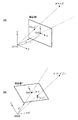
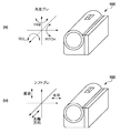
最初に、本明細書において使用する言葉の定義について説明する。本明細書において、撮像装置の動きを「装置ブレ」とし、装置ブレによって発生する撮像画像の変形を「像ブレ」とする。図5(a)および(b)に示すように、「装置ブレ」にはヨー(YAW)、ピッチ(PITCH)、ロール(ROLL)方向の3種類の「角度ブレ」と、水平、垂直、光軸方向の3種類の「シフトブレ」が存在する。方向を指定しない「装置ブレ」は装置の動きに関するこれら6種類の方向成分の総称である。また、方向を指定しない「像ブレ」は、図6(a)〜(f)に示す、並進(水平および垂直)、回転、あおり(水平および垂直)、拡大縮小、せん断の8種類の像変形の総称である。 First, definitions of terms used herein will be described. In the present specification, the movement of the imaging device is referred to as "device blur", and the deformation of the captured image caused by the device blur is referred to as "image blur". As shown in FIGS. 5 (a) and 5 (b), there are three types of "equipment blur" in the yaw (YAW), pitch (PITCH), and roll (ROLL) directions, and horizontal, vertical, and optical. There are three types of "shift blur" in the axial direction. "Device blur" that does not specify a direction is a general term for these six types of directional components related to the movement of a device. In addition, there are eight types of image deformation that do not specify the direction, as shown in FIGS. 6 (a) to 6 (f): translation (horizontal and vertical), rotation, tilt (horizontal and vertical), enlargement / reduction, and shearing. It is a general term for.
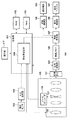
図1は、本発明の実施形態に係る画像処理装置の一例としてのデジタルビデオカメラ100(以下、単にビデオカメラ100という)の機能構成例を示すブロック図である。なお、図1にはビデオカメラ100が有する構成のうち、実施形態を説明する上で必要となる構成のみを記載している点に留意されたい。
FIG. 1 is a block diagram showing a functional configuration example of a digital video camera 100 (hereinafter, simply referred to as a video camera 100) as an example of an image processing device according to an embodiment of the present invention. It should be noted that FIG. 1 shows only the configurations necessary for explaining the embodiment among the configurations of the
制御部101は例えばCPUであり、例えばROM132に記憶されたプログラムをRAM133に読み込んで実行し、ビデオカメラ100の各部を制御することによりビデオカメラ100の機能を実現する。ROM132は例えば書き換え可能な不揮発性メモリであり、制御部101のCPUが実行可能なプログラム、設定値、GUIデータなどを記憶する。RAM133は、制御部101のCPUが実行するプログラムを読み込んだり、プログラムの実行中に必要な値を保存したりするために用いられる。
The
なお、図1において、変形量演算部200は、制御部101がプログラムを実行することによって実現する機能のうち、実施形態に特に関連する機能を機能ブロックとして記載したものである。
In FIG. 1, the deformation
動きセンサ102は、撮像装置100の動きである装置ブレを表す動き信号を出力する。動きセンサ102は例えば3軸角速度センサであってよい。なお、シフトブレは3軸加速度センサによって検出してもよい。
The
A/D変換器103は、動きセンサ102が出力する動き信号をA/D変換して制御部101に供給する。なお、動きセンサ102がデジタル形式の動き信号を出力する場合、A/D変換器103は不要である。
The A / D converter 103 A / D-converts the motion signal output by the
撮像光学系120は変倍レンズ121やフォーカスレンズといった可動レンズを含むレンズ群と、絞りとを有し、被写体像を撮像素子123の撮像面に結像する。撮像素子123は光電変換部を有する画素が2次元的に配置された画素アレイを有する。撮像素子123は、撮像面に結像された被写体像を画素アレイによってアナログ画素信号群(アナログ画像信号)に変換して信号処理部124に出力する。撮像素子123の動作は制御部101が制御する。
The imaging
本実施形態では、撮像光学系120の被写体側の端部にアナモフィックレンズ122が着脱可能に取り付けられている。アナモフィックレンズ122は、被写体像を特定の一方向(ここでは撮像素子123の画素アレイの長辺に平行な方向とする)に圧縮する効果を有する光学系である。アナモフィックレンズ122は、回転非対称な像を結像する(被写体像を圧縮して結像する)レンズの一例である。なお、撮像光学系120は交換可能であってもよいし、ビデオカメラ100に固定されていてもよい。また、アナモフィックレンズ122は、撮像光学系120に着脱可能であってもよいし、撮像光学系120に組み込まれていてもよい。以下、アナモフィックレンズ122の形態に関わらず、撮像素子123に結像される被写体像が特定の一方向に圧縮されている状態を、ビデオカメラ100にアナモフィックレンズが装着された状態という。
In the present embodiment, the
ズームエンコーダ119は、変倍レンズ121の位置(ズーム位置)を検出し、制御部101(変形量演算部200)に出力する。また、撮像光学系120は、フォーカスレンズの位置や絞り値についてもズーム位置と同様に制御部101に出力する。制御部101が変倍レンズ121およびフォーカスレンズの位置を制御することにより、撮像光学系120の焦点距離(画角)や合焦距離を制御する。
The
操作部117は、ユーザがビデオカメラ100に各種の指示を入力するために設けられた入力デバイス(ボタン、スイッチ、ダイヤルなど)の総称である。操作部117に対するユーザ操作は制御部101によって検出される。操作部117を構成する入力デバイスは、割り当てられた機能に応じた名称を有する。例えば、操作部117には、レリーズスイッチ、動画記録スイッチ、撮影モードを選択するための撮影モード選択ダイヤル、メニューボタン、方向キー、決定キーなどが含まれる。レリーズスイッチは静止画記録用のスイッチであり、制御部101はレリーズスイッチの半押し状態を撮影準備指示、全押し状態を撮影開始指示と認識する。また、制御部101は、動画記録スイッチが撮影スタンバイ状態で押下されると動画の記録開始指示と認識し、動画の記録中に押下されると記録停止指示と認識する。なお、同一の入力デバイスに割り当てられる機能は可変であってよい。また、入力デバイスはタッチディスプレイを用いたソフトウェアボタンもしくはキーであってもよい。また、操作部117は、音声入力や視線入力など、非接触な入力方法に対応した入力デバイスを含んでもよい。
The
信号処理部124は、撮像素子123からのアナログ画像信号に対して予め定められた画像処理を適用し、信号や画像データを生成したり、各種の情報を取得および/または生成したりする。信号処理部124は例えば特定の機能を実現するように設計されたASICのような専用のハードウェア回路であってもよいし、DSPのようなプログラマブルプロセッサがソフトウェアを実行することで特定の機能を実現する構成であってもよい。また、信号処理部124の機能の少なくとも一部は、制御部101がプログラムを実行することによって実現してもよい。
The
ここで、信号処理部124が適用する画像処理には、前処理、色補間処理、補正処理、データ加工処理、評価値算出処理、特殊効果処理などが含まれる。前処理には、A/D変換、信号増幅、基準レベル調整、欠陥画素補正などが含まれる。色補間処理は、画素から読み出した画像データに含まれていない色成分の値を補間する処理であり、デモザイク処理や同時化処理とも呼ばれる。補正処理には、ホワイトバランス調整、階調補正(ガンマ処理)、撮像光学系120の光学収差や周辺減光の影響を補正する処理、色を補正する処理などが含まれる。データ加工処理には、合成処理、スケーリング処理、符号化および復号処理、ヘッダ情報生成処理などが含まれる。評価値算出処理は、自動焦点検出(AF)に用いる信号や評価値の生成、自動露出制御(AE)に用いる評価値の算出処理などである。特殊効果処理には、ぼかしの付加、色調の変更、リライティング処理などが含まれる。なお、これらは信号処理部124が適用可能な画像処理の例示であり、信号処理部124が適用する画像処理を限定するものではない。
Here, the image processing applied by the
動画撮影時に信号処理部124は、撮像素子123が所定のフレームレートで出力するアナログ画像信号に対して画像処理を適用してフレーム画像データを生成し、画像メモリ125に順次書き込む。
At the time of moving image shooting, the
画像変形部127は、変形量演算部200で算出された画像変形量に基づいて、画像メモリ125に格納された画像データに対して幾何学的な変形処理を適用することにより、像ブレを補正する。画像変形部127の動作の詳細については後述する。設定などにより像ブレ補正を行わない場合、画像変形部127は幾何学的な変形処理を適用しない。
The
画像変形部127の出力する画像データは、記録制御部128および表示制御部130に出力される。なお、信号処理部124が画像メモリ125に書き込むフレーム画像データの形式によっては、記録や表示に用いるために現像処理、スケーリング処理、符号化処理などが必要な場合がある。この場合、画像変形部127の出力する画像データに対して信号処理部124で必要な処理を適用してから記録制御部128および表示制御部130に出力してもよい。あるいは、画像変形部127から供給される画像データから、記録制御部128および表示制御部130が、それぞれ記録用の画像データおよび表示用の画像データを生成してもよい。
The image data output by the
表示制御部130はビデオメモリ(VRAM)を有し、ビデオメモリに格納された表示用画像データに基づく信号を表示デバイス131に供給する。表示用画像データは、画像変形部127もしくは信号処理部124から供給される画像データであってもよいし、画像変形部127から供給される画像データに基づいて表示制御部130が生成してもよい。表示デバイス131は例えばLCDである。表示デバイス131はタッチディスプレイであってもよい。
The
記録制御部128はバッファメモリを有し、バッファメモリに格納された記録用画像データに基づく画像データファイルを記録媒体129に記録する。記録用画像データは、画像変形部127もしくは信号処理部124から供給される画像データであってもよいし、画像変形部127から供給される画像データに基づいて記録制御部128が生成してもよい。記録媒体129は例えば半導体メモリカードである。なお、記録媒体129は外部の記録装置であってもよい。なお、記録制御部128による記録は、操作部117を通じてユーザから撮影開始指示(静止画)や記録開始指示(動画)が入力されたことに応じて開始される。
The
ここで、アナモフィックレンズ122の特性に関する情報の取得方法について説明する。アナモフィックレンズ122の特性とは、例えば光学像の圧縮率や圧縮方向、歪曲補正情報などである。なお、アナモフィックレンズ122の光学像の圧縮方向は基本的に撮像素子123の画素アレイの長辺に平行な方向であるため、圧縮方向の情報はなくてもよい。
Here, a method of acquiring information regarding the characteristics of the
撮影光学系120がアナモフィックレンズ122を含んだ交換レンズである場合、撮影光学系120が有する制御部との通信により、制御部101はアナモフィックレンズ122の特性に関する情報を取得可能である。一方、アナモフィックレンズ122がコンバージョンレンズやアダプタであるなど、制御部101と通信できない構成の場合には、例えば操作部117に対するユーザ操作によりユーザがアナモフィックレンズ122の特性に関する情報を設定することができる。あるいは、アナモフィックレンズ122の型番などを指定して外部装置から通信によって情報を取得してもよい。アナモフィックレンズ122の特性に関する情報は、取得方法にかかわらず、変形量演算部200に供給される。
When the photographing
変形量演算部200は、動きセンサ102の出力する動き信号、ズームエンコーダ119の出力するズーム位置、およびアナモフィックレンズ122の特性に関する情報とを用いて、像ブレを補正するための幾何学的な変形を表す画像変形量を算出する。そして、変形量演算部200は、算出した画像変形量を画像変形部127に設定する。変形量演算部200の処理の詳細は後述する。
The deformation
(画像変形部127の動作)
画像変形部127は、例えば射影変換などを用いて、画像データに対して幾何学的な画像変形処理を適用する。撮像画像において、撮像光学系120の光軸に対応する画像座標を原点とし、画素アレイの長辺に沿う方向をX軸、短辺に沿う方向をY軸とする直交座標系を規定する。そして、画像メモリ125に格納された変形前の画像における画素座標を(X0,Y0)、変形後の画像における画素座標を(X1,Y1)とする。この場合、変形前後の画素座標の関係は、同次座標表現を用いると(式1)のように記述することができる。
The
また(式1)における3×3の行列は一般的に射影変換行列と呼ばれ、行列の要素h1からh8は、変形量演算部200が画像変形量として画像変形部127に設定する。なお、以下の説明では、画像変形部127が射影変換を用いて幾何学的な変形を実現するものとするが、例えばアフィン変換など、他の公知の幾何学的変換手法を用いてもよい。
Further, the 3 × 3 matrix in (Equation 1) is generally called a projective transformation matrix, and the elements h1 to h8 of the matrix are set by the deformation
(変形量演算部200の動作)
次に、変形量演算部200の動作の詳細について説明する。変形量演算部200は、動き信号から得られる装置ブレの角度と、ズーム位置から得られる撮像光学系120の焦点距離と、アナモフィックレンズ122の特性に関する情報とを用いて画像変形量を算出する。具体的には、変形量演算部200は(式1)の射影変換行列を画像変形量として算出する。
(Operation of deformation amount calculation unit 200)
Next, the details of the operation of the deformation
本実施形態において変形量演算部200は、まず、動き信号から得られる装置ブレの角度と、ズーム位置から得られる撮像光学系120の焦点距離とから射影変換行列を算出する。そして、変形量演算部200は、アナモフィックレンズ122の特性に関する情報を用いて射影変換行列を補正し、補正後の射影変換行列を画像変形量として画像変形部127に設定する。
In the present embodiment, the deformation
まず、装置ブレの角度と撮像光学系120の焦点距離とを用いた射影変換行列の算出動作について説明する。図2(a)は、ビデオカメラ100による被写体像の撮像面への投影を、ピンホールカメラモデルを用いて示した斜視図である。ピンホールカメラモデルにおけるピンホールの位置を原点(0,0,0)とするXYZ空間座標を考える。撮像面をピンホールよりも後ろ側に配置すると、撮像面に投影される被写体像が倒立するため、図2(a)では仮想的にピンホール位置よりも前(被写体側)に撮像面Iを配置している。
First, the operation of calculating the projective transformation matrix using the angle of the device shake and the focal length of the imaging
XYZ空間座標の原点(0,0,0)と撮像面IとのZ軸方向の距離は、撮像光学系120の焦点距離fに相当する。撮像面I上の座標はXYZ座標系のZ軸と撮像面との光源を原点(0,0)とするuv平面座標系を設定する。したがって、uv平面座標系の原点は、XYZ座標系における座標(0,0,f)になる。なお、X軸とu軸、Y軸とv軸はそれぞれ同じ方向を有する。
The distance between the origin (0,0,0) of the XYZ spatial coordinates and the imaging surface I in the Z-axis direction corresponds to the focal length f of the imaging
この場合、uv平面座標系の座標P(u,v)は、XYZ空間座標系における被写体の座標A(X,Y,Z)が、撮像面Iに投影された座標である。したがって、座標Pと座標Aとの関係は(式4)で表すことができる。
(式4)は、同次座標を用いると、(式5)で表すことができる。
図2(b)は、図2(a)のピンホールカメラモデルを、Z軸を回転軸として回転させた状態を示している。図2(b)において、X’Y’Z’空間座標系は、XYZ空間座標系をZ軸周りに回転した座標系である。X’Y’Z’空間座標系の原点(0,0,0)は、XYZ空間座標系と一致している。つまり、図2(b)は、ビデオカメラ100の動き(装置ブレ)がロール方向の角度ブレ成分のみを有し、シフトブレ成分および、ヨー、ピッチ方向の角度ブレ成分を有していない状態を表現している。
FIG. 2B shows a state in which the pinhole camera model of FIG. 2A is rotated with the Z axis as the rotation axis. In FIG. 2B, the XYZ ′ spatial coordinate system is a coordinate system obtained by rotating the XYZ spatial coordinate system around the Z axis. The origin (0,0,0) of the XYZ'spatial coordinate system coincides with the XYZ spatial coordinate system. That is, FIG. 2B represents a state in which the movement (device blur) of the
図2(a)と図2(b)とにおいて、座標系間の関係に変化はない。したがって、図2(b)におけるu’v’平面座標系の原点(0,0)は、X’Y’Z’空間座標系における座標(0,0,f)である。また、u’v’平面座標系の座標P’(u’,v’)は、X’Y’Z’空間座標系における被写体の座標A’(X’,Y’,Z’)が、撮像面I’に投影された座標である。したがって、座標P’と座標A’との関係は、同次座標を用いると、(式6)と同様に(式7)で表すことができる。
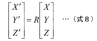
また、図2(a)における被写体の座標Aと、図2(b)における被写体の座標A’とは、世界座標系において変化していない(すなわち、静止している)ため、座標Aと座標A’との関係は、装置ブレのロール方向成分をRとすると、(式8)で表すことができる。
さらに、(式6)および(式7)を変形して(式8)に代入すると(式9)が得られる。
(式9)は、ピンホールカメラモデルの回転前後における、撮像面上の座標(u,v)と座標(u’,v’)の対応関係を表している。換言すれば、(式9)は、ビデオカメラ100の装置ブレのロール方向成分によって生じる撮像面上での画素位置の移動を表している。そのため、(式9)を変形して、回転後の座標(u’,v’)から回転前の座標(u,v)を得る(式10)により、ロール方向の像ブレを補正することができる。
したがって、ロール方向の像ブレを補正するための画像変形量を表す射影変換行列Hは(式11)で表される。
ここでは説明および理解を容易にするため、装置ブレがロール方向のみを有するものとして説明したが、装置ブレが他の方向成分を含む場合も、Rの成分を増やすことによって同様の考え方が適用できる。ここで、装置ブレのヨー方向成分をθy、ピッチ方向成分をθp、ロール方向成分をθrとすると、上述した式におけるRは(式12)で表すことができる。
そして、(式11)に示した、像ブレを補正するための射影変換行列Hは、(式13)を用いて、並進t→、拡大縮小s(定数)、回転r(行列)、せん断k(行列)、あおりν→の各変形成分に分解することができる。
ty … 垂直並進
θ … 回転角
νx … 水平あおり
νy … 垂直あおり
α … せん断の非等方倍率
φ … せん断の方向角
Then, the projective transformation matrix H for correcting the image blur shown in (Equation 11) uses (Equation 13) to translate t → , enlargement / reduction s (constant), rotation r (matrix), and shear k. It can be decomposed into each deformation component of (matrix) and shear ν →.
t y … Vertical translation θ… Rotation angle ν x … Horizontal tilt ν y … Vertical tilt α… Shear asymmetric magnification φ… Shear direction angle
(式11)〜(式13)より、各変形成分に対する方程式を解くと、(式14)〜(式21)が得られる。
本実施形態では、変形量演算部200の処理負荷を軽減するため、以下に説明するように演算を簡略化する。ビデオカメラ100の角度ブレは、パンニングなど、ユーザーが意図的にビデオカメラ100を動かす場合を除き、それほど大きくならない。よって、ビデオカメラ100の角度ブレの大きさ(ブレ角度)がγのとき、cosγ=1、sinγtanγ=0、sinγsinγ=0と近似すると、(式14)〜(式21)の近似式(式22)〜(式29)が得られる。
このとき、(式27)〜(式29)からわかるように、拡大縮小の倍率sは1、せん断の非等方倍率αは1、方向角tanφは0度となる。すなわち、ビデオカメラ100の角度ブレに起因する像ブレの変形成分において、拡大縮小およびせん断の成分は、他の変形成分と比較して小さい。
At this time, as can be seen from (Equation 27) to (Equation 29), the enlargement / reduction magnification s is 1, the shear anisotropic magnification α is 1, and the azimuth angle tanφ is 0 degrees. That is, in the deformation component of the image blur caused by the angle blur of the
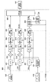
次に、図3を用いて、変形量演算部200の機能構成と動作の一例について具体的に説明する。なお、以下の説明において変形量演算部200が有する機能ブロックを主体として説明される動作は、実際には制御部101がプログラムを実行することによって実現される。
Next, an example of the functional configuration and operation of the deformation
なお、(式22)、(式23)から、装置ブレのヨー方向成分θyによって、像ブレには水平方向の並進txおよび水平方向のあおりνxの変形成分が生じることが分かる。また、(式25)、(式26)から、装置ブレのピッチ方向成分θpによって、像ブレには垂直方向の並進tyおよび垂直方向のあおりνyの変形成分が生じることが分かる。 From (Equation 22) and (Equation 23), it can be seen that the yaw direction component θy of the device blur causes a deformation component of horizontal translation t x and horizontal tilt ν x in the image blur. Further, from (Equation 25) and (Equation 26), it can be seen that the pitch direction component θp of the device blur causes the vertical translation t y and the vertical tilt ν y deformation component to occur in the image blur.
方向が異なる同種の変形成分については同じ処理によって補正することができる。そのため、以下では一つの方向の変形成分の補正処理についてのみ説明する。
図3において、符号201から205のブロックは、像ブレの並進変形成分の補正量を算出する。符号211から215までのブロックは、像ブレのあおり変形成分の補正量を算出する。また、符号221および223から226までのブロックは、像ブレの回転変形成分の補正量を算出する。符号227のブロックは、アナモフィックレンズが含まれる場合に、回転変形成分を補正したときに画像を正しく変形するためのせん断変形成分の補正量を算出する。
The same type of deformation component in different directions can be corrected by the same process. Therefore, in the following, only the correction processing of the deformation component in one direction will be described.
In FIG. 3, the blocks of
まず、並進変形成分の補正量の算出について説明する。HPF201には、A/D変換器103の出力のうち、ヨー方向またはピッチ方向の角速度データが供給される。HPF201は角速度データに含まれる低周波数成分を遮断して高周波数帯域の信号を出力する。HPF201のカットオフ周波数は例えば実験的に予め定めることができる。また、HPF201のカットオフ周波数は可変であってよい。なおHPF201は必須ではなく、A/D変換器103からの出力を乗算器202に直接供給してもよい。
First, the calculation of the correction amount of the translational deformation component will be described. Of the output of the A /
焦点距離取得部231は、ズームエンコーダ119が出力するズーム位置に基づいて撮像光学系120の焦点距離fを取得する。焦点距離取得部213は取得した焦点距離fを乗算器202および除算器212に出力する。ズーム位置から焦点距離を求める方法に特に制限はなく、公知の任意の方法を用いることができる。例えば、ズーム位置と焦点距離との関係を関数またはテーブルとして保持しておき、ズーム位置を関数に代入したり、ズーム位置を用いてテーブルを参照したりすることにより焦点距離を得ることができる。関数やテーブルなど、ズーム位置から焦点距離を求めるための情報は撮像光学系120から取得してもよい。また、ズームエンコーダ119が焦点距離を直接出力可能な場合、焦点距離取得部231は不要である。
The focal
乗算器202は、HPF201の出力に、焦点距離取得部231の出力する焦点距離fを乗算し、センタリング部203に供給する。
The
センタリング部203は、ビデオカメラ100のヨー方向またはピッチ方向の動きが一定量を超える場合に、ブレ補正量をゼロに戻す入力値(以下、センタリング量とする)を、乗算器202の出力に加算する。センタリング量の大きさは可変であってよい。なおセンタリング部203は必須ではなく、乗算器202の出力を積分器204に直接供給してもよい。
The centering
積分器204は、センタリング部203からの出力を積分し、積分値を飽和防止部205に供給する。積分器204の時定数は可変であってよい。
The
飽和防止部205は、積分器204から供給される積分値が所定の閾値を超えないように制限する。飽和防止部205は、例えば積分値と閾値との差が所定値未満になると、積分値の増加を抑制する。例えば飽和防止部205は、(1)HPF201のカットオフ周波数を高くする、(2)積分器204の時定数を短くする、(3)センタリング部203のセンタリング量を大きくする、の1つ以上を実行することにより、積分値の増加を抑制する。なお、これらの制御によっても積分器204の出力が閾値を超える場合、飽和防止部205は閾値に等しい値を出力する。飽和防止部205の出力は、像ブレの並進変形成分の補正量として変形量合成部230に供給される。
The
次に、あおり変形成分の補正量の算出について説明する。あおり変形成分の補正量を算出する符号211から215までのブロックは、乗算器202と除算器212の処理を除いて、符号201から205までのブロックとそれぞれ同じ処理を行う。そのため、除算器212についてのみ説明し、ブロック211、212〜215についての説明は省略する。
Next, the calculation of the correction amount of the tilt deformation component will be described. The blocks of
除算器212は、HPF201の出力を焦点距離取得部231の出力する焦点距離fで除算し、センタリング部203に供給する。除算器212は焦点距離fの逆数1/fを乗算する乗算器としてもよい。焦点距離fでの除算は、(式25)および(式26)に示したあおり変形成分の算出式に基づく。飽和防止部215の出力は、像ブレにおけるあおり変形成分の補正量として変形量合成部230に供給される。
The
次に、回転変形成分の補正量の算出について説明する。HPF221には、A/D変換器103の出力のうち、ロール方向の角速度データが供給される。HPF221は角速度データに含まれる低周波数成分を遮断して高周波数帯域の信号を出力する。HPF221のカットオフ周波数は例えば実験的に予め定めることができる。また、HPF221のカットオフ周波数は可変であってよい。なおHPF221は必須ではなく、A/D変換器103からの出力をセンタリング部223に直接供給してもよい。
Next, the calculation of the correction amount of the rotational deformation component will be described. Of the output of the A /
センタリング部223は、ビデオカメラ100のロール方向の動きが一定量を超える場合に、センタリング部203、213と同様にセンタリング量を、HPF221の出力に加算する。なおセンタリング部223は必須ではなく、HPF221またはA/D変換器103からの出力を積分器224に直接供給してもよい。
When the movement of the
積分器224は、センタリング部203からの出力を積分し、積分値を飽和防止部225に供給する。
The
飽和防止部225は、積分器224から供給される積分値が所定の閾値を超えないように制限する。飽和防止部225は、例えば積分値と閾値との差が所定値未満になると、積分値の増加を抑制する。例えば飽和防止部225は、(1)HPF221のカットオフ周波数を高くする、(2)積分器224の時定数を短くする、(3)センタリング部223のセンタリング量を大きくする、の1つ以上を実行することにより、積分値の増加を抑制する。なお、これらの制御によっても積分器224の出力が閾値を超える場合、飽和防止部225は閾値に等しい値を出力する。
The
飽和防止部225は、ビデオカメラ100にアナモフィックレンズが装着されているか否かに応じて積分値の閾値を変更する。アナモフィックレンズの装着有無に応じた閾値は予め設定しておくことができる。飽和防止部225の出力は、補正量修正部226に供給される。
The
補正量修正部226は、ビデオカメラ100にアナモフィックレンズが装着されている際に、アナモフィックレンズの圧縮率に応じて回転変形成分の補正量を修正する。補正量の修正方法については、後で詳しく説明する。補正量修正部226の出力は、回転変形成分の補正量として変形量合成部230に供給されるとともに、せん断算出部227にも供給される。
When the anamorphic lens is attached to the
せん断算出部227は、ビデオカメラ100にアナモフィックレンズが装着されている際の回転変形成分の補正において、被写体像を正しく変形させるためのせん断の補正量を算出する。せん断の補正量の算出については、後で詳しく説明する。せん断算出部227の出力はせん断補正量として変形量合成部230に供給される。
The
変形量合成部230は、飽和防止部205および215、補正量修正部226、およびせん断算出部227から供給される、像ブレの各変形成分の補正量を合成する。具体的には変形量合成部230は(式13)に従って(式1)の射影変換行列を算出する。変形量合成部230は、算出した射影変換行列の各要素の値を、画像変形部127に出力(設定)する。画像変形部127は、変形量合成部230が設定した射影変換行列を用いた幾何学変形を画像データに適用することにより、像ブレを補正する。
The deformation
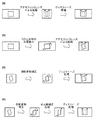
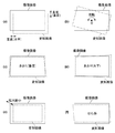
次に、アナモフィックレンズによって生じる画像変形と、それを表す射影変換行列について説明する。図4(a)は、アナモフィックレンズによって被写体像を撮像面の水平方向に圧縮(スクイーズ)して記録し、被写体像を撮影後に水平方向に引き伸ばし(ディスクイーズ)して再生する手順において生じる画像変形を模式的に示す図である。ここでは一例として、撮影範囲にカメラに正対する正方形の被写体が1つ存在する場合を示している。例えばアナモフィックレンズの水平方向の圧縮率が1/2(垂直方向の圧縮はなし)であるとすると、撮像面に結像される被写体像は、水平方向の大きさが1/2に圧縮されるため、正方形の被写体は縦長の長方形に変形した像で記録される。再生時に画像を水平方向に2倍引き伸ばすディスクイーズ処理することにより、アナモフィックレンズによる圧縮効果が取り除かれ、被写体の形状が正方形に戻る。 Next, the image deformation caused by the anamorphic lens and the projective transformation matrix representing the deformation will be described. FIG. 4A shows image deformation that occurs in a procedure in which a subject image is compressed (squeezed) in the horizontal direction of the imaging surface by an anamorphic lens and recorded, and the subject image is stretched (discise) in the horizontal direction after shooting and reproduced. Is a diagram schematically showing. Here, as an example, a case where one square subject facing the camera exists in the shooting range is shown. For example, if the horizontal compression ratio of the anamorphic lens is 1/2 (no vertical compression), the horizontal size of the subject image imaged on the imaging surface is compressed to 1/2. , A square subject is recorded as an image transformed into a vertically long rectangle. The disc-easing process, which stretches the image twice in the horizontal direction during playback, removes the compression effect of the anamorphic lens and returns the shape of the subject to a square.
アナモフィックレンズによる水平方向の圧縮率がa(<1)、水平方向の圧縮率が1(圧縮なし)とすると、アナモフィックレンズによる画像変形は、(式30)の射影変換行列で表現することができる。
なお、圧縮率aは、1/2に圧縮する場合0.5となる。アナモフィックレンズの圧縮率aとしては、0.5あるいは0.75が一般的であるが、特に制限はない。また、垂直方向についても圧縮されてもよい。アナモフィックレンズの圧縮率(あるいは圧縮率の逆数である倍率)は、制御部101がレンズユニットから取得したり、ユーザが設定したりすることができる。
The compression ratio a is 0.5 when compressed to 1/2. The compressibility a of the anamorphic lens is generally 0.5 or 0.75, but is not particularly limited. It may also be compressed in the vertical direction. The compression rate of the anamorphic lens (or the magnification that is the reciprocal of the compression rate) can be acquired by the
図4(a)に示したように、アナモフィックレンズを用いて撮影され、記録された画像は、ディスクイーズ処理によって圧縮の効果を除去することにより、変形のない画像に戻すことができる。圧縮率aで記録された画像のディスクイーズ処理は、(式31)の射影変換行列で表現することができる。
次に、ビデオカメラ100にアナモフィックレンズが装着された状態の撮影において、ビデオカメラ100にロール方向の角度ブレが生じた場合を考える。図4(b)は、ビデオカメラ100にロール方向の角度ブレが生じたときにアナモフィックレンズにより撮像面に結像される被写体像について模式的に示している。
Next, consider a case where an angular blur in the roll direction occurs in the
ここでも図4(a)と同様の撮影シーンであるとすると、被写体が回転した状態で撮像面の水平方向に圧縮された被写体像が結像されるため、正方向の被写体は平行四辺形の像で記録される。このときの画像変形を表す射影変換行列は、ロール方向の角度ブレを表す射影変換行列と、アナモフィックレンズによる画像変形の射影変換行列(式31)との組み合わせによって表現できる。 Again, assuming that the shooting scene is the same as in FIG. 4A, a subject image compressed in the horizontal direction of the imaging surface is formed while the subject is rotated, so that the subject in the positive direction is a parallelogram. Recorded as a statue. The projective transformation matrix representing the image deformation at this time can be expressed by a combination of the projective transformation matrix representing the angular blur in the roll direction and the projective transformation matrix of the image transformation by the anamorphic lens (Equation 31).
ロール方向の角度ブレをθrとすると、(式12)の右辺の第3項の射影変換行列として表現できる。これに、アナモフィックレンズによる画像変形の射影変換行列(式31)と組み合わせると、アナモフィックレンズを用いた撮影時の角度ブレによって生じる画像変形は、(式32)の射影変換行列で表すことができる。
ここで、ロール方向の回転変形を補正するために、回転角を(−θr)とした、(式33)の射影変換行列Hを考える。
(式32)に(式33)の射影変換行列Hを適用することによって単純にθrの回転変形を補正を行うと、(式34)のようになってしまう。
(式34)においても(式31)と同様に(u”,v”)がディスクイーズ処理後の画像上の座標を表す。(式34)から、回転変形を補正した画像をディスクイーズ処理しても、被写体の形が正方形には戻らず、歪んだ形状になることが分かる。 In (Equation 34) as well, (u ", v") represents the coordinates on the image after the disk ease processing as in (Equation 31). From (Equation 34), it can be seen that the shape of the subject does not return to a square shape but becomes a distorted shape even if the image corrected for rotational deformation is subjected to disc-easing processing.
図4(c)は、(式34)を用いて回転変形を補正し、ディスクイーズ処理した際に生じる問題を模式的に示した図である。このように、アナモフィックレンズによって圧縮された被写体像が角度ブレによって変形した場合、通常の回転変形補正では対応できないことがわかる。 FIG. 4C is a diagram schematically showing a problem that occurs when the rotational deformation is corrected by using (Equation 34) and the disc ease processing is performed. As described above, when the subject image compressed by the anamorphic lens is deformed due to the angular blur, it can be seen that the normal rotational deformation correction cannot cope with it.
そこで、本実施形態では、アナモフィックレンズの圧縮率を考慮したロール方向の回転変形補正とせん断処理とを用いて、アナモフィックレンズを装着時のロール方向の角度ブレによって生じる像ブレを正しく補正する。 Therefore, in the present embodiment, the image blur caused by the angular blur in the roll direction when the anamorphic lens is attached is correctly corrected by using the rotational deformation correction in the roll direction and the shearing process in consideration of the compression rate of the anamorphic lens.
図4(d)は、本実施形態の補正方法を模式的に示した図である。図4(c)との比較から分かるように、ロール方向の角度ブレに起因する回転変形を補正した後、ディスクイーズ処理の前にせん断補正処理を適用することにより、適切に像ブレを補正することができる。 FIG. 4D is a diagram schematically showing the correction method of the present embodiment. As can be seen from the comparison with FIG. 4C, the image blur is appropriately corrected by applying the shear correction process before the disk ease process after correcting the rotational deformation caused by the angular blur in the roll direction. be able to.
以下、図4(d)に示した補正処理を実現する射影変換行列について説明する。アナモフィックレンズによる圧縮によって生じる被写体像の歪みを考慮して、(式35)に示すような回転補正とせん断による射影変換行列を用いる。
(式39)の射影変換行列を用いると、ディスクイーズ処理を含めた座標変換は(式41)のように表現できる。
(1):ビデオカメラ100に加わるロール方向の角度ブレ(回転角:θr)
(2):アナモフィックレンズによる水平方向の圧縮(圧縮率:a)
(3):ロール方向の角度ブレによる回転変形の補正(回転角:Φ、ただし、tanΦ=1/a・tanθr)
(4):せん断処理(せん断の非等方倍率:B=cosΦ/cosθr、せん断の方向角:γ−Φ、ただし、tanγ=a・tanθr)
(5):ディスクイーズ処理(水平方向の拡大率:1/a)
Using the projective transformation matrix of (Equation 39), the coordinate transformation including the disk ease processing can be expressed as (Equation 41).
(1): Angle blur in the roll direction applied to the video camera 100 (rotation angle: θr)
(2): Horizontal compression by an anamorphic lens (compression rate: a)
(3): Correction of rotational deformation due to angular deviation in the roll direction (rotation angle: Φ, but tanΦ = 1 / a ・ tanθr)
(4): Shear treatment (anisotropy of shear: B = cosΦ / cosθr, shear direction angle: γ−Φ, where tanγ = a · tanθr)
(5): Disc ease processing (horizontal enlargement ratio: 1 / a)
(式41)の結果から、(u”,v”)=(u,v)となり、像ブレが正しく補正されることがわかる。このように、アナモフィックレンズ装着時の撮影においてロール方向の角度ブレ振れが生じた状態でも、(3)回転変形補正および(4)せん断処理を適用することにより、適切に像ブレが補正されたディスクイーズ処理後の画像を得ることができる。 From the result of (Equation 41), it can be seen that (u ", v") = (u, v) and the image blur is corrected correctly. In this way, even when the angle blurring in the roll direction occurs during shooting with the anamorphic lens attached, the disc is appropriately corrected for image blurring by applying (3) rotational deformation correction and (4) shearing treatment. The image after the shear processing can be obtained.
変形量演算部200は、ビデオカメラ100にアナモフィックレンズが装着されている場合、(式13)の回転変形成分rとして(式41)の(3)の行列を、せん断変形成分kとして(式41)の(4)の行列をそれぞれ用い、(式1)の射影変換行列を算出する。
また、変形量演算部200は、ビデオカメラ100にアナモフィックレンズが装着されていない場合には、(式13)をそのまま用いて(式1)の射影変換行列を算出する。
When the
Further, when the
本実施形態においては、説明および理解を容易にするため、アナモフィックレンズが撮像面の水平方向にのみ被写体像を圧縮する場合について説明した。しかし、アナモフィックレンズが垂直方向に被写体像を圧縮する場合や、水平および垂直方向に異なる圧縮率で被写体像を圧縮する場合であっても、圧縮方向ごとに同様の補正を行うことで対応可能である。 In the present embodiment, in order to facilitate explanation and understanding, a case where the anamorphic lens compresses the subject image only in the horizontal direction of the imaging surface has been described. However, even if the anamorphic lens compresses the subject image in the vertical direction or compresses the subject image with different compression ratios in the horizontal and vertical directions, it is possible to handle it by performing the same correction for each compression direction. be.
以上説明したように、本実施形態においては、アナモフィックレンズによる圧縮を考慮したロール方向の回転変形補正とせん断処理を行う。これにより、アナモフィックレンズのような回転非対称な像を結像するレンズを装着した撮影時に光軸回りの装置ブレが生じた場合でも、適切な像ブレ補正が実現できる。 As described above, in the present embodiment, the rotational deformation correction and the shearing process in the roll direction in consideration of the compression by the anamorphic lens are performed. As a result, even when device blurring around the optical axis occurs during shooting with a lens that forms a rotationally asymmetrical image such as an anamorphic lens, appropriate image blurring correction can be realized.
なお、図4(d)では、正方形の被写体の上下の2辺が画像中の水平方向と平行となるように回転変形補正したのち、左右方向のせん断補正処理を行っているが、その他の回転変形補正およびせん断補正処理を行ってもよい。例えば、正方形の被写体の左右の2辺が画像中の垂直方向と平行となるように回転変形補正したのち、上下方向のせん断補正処理を行ってもよい。 In FIG. 4D, after correcting the rotation deformation so that the upper and lower two sides of the square subject are parallel to the horizontal direction in the image, the shear correction processing in the left-right direction is performed, but other rotations. Deformation correction and shear correction processing may be performed. For example, after correcting the rotational deformation so that the two left and right sides of the square subject are parallel to the vertical direction in the image, the shear correction process in the vertical direction may be performed.
また、アナモフィックレンズではなく、被写体像を撮像素子123の画素アレイの短辺に平行な方向に圧縮する効果を有する光学系を用いた場合でも本発明は適用可能である。その他、被写体像を撮像素子123の画素アレイの短辺に平行な方向および長辺に平行な方向に圧縮するが短辺に平行な方向の圧縮率と長辺に平行な方向の圧縮率とが異なる効果を有する光学系を用いた場合でも本発明は適用可能である。すなわち、被写体像を光軸と直交する第1の方向および第2の方向の少なくとも一方に圧縮し、第1の方向を第2の方向よりも相対的に圧縮する(第1の方向と第2の方向とで圧縮率が異なる)効果を有する光学系を用いた場合に本発明は適用可能である。
Further, the present invention can be applied even when an optical system having an effect of compressing a subject image in a direction parallel to the short side of the pixel array of the
(その他の実施形態)
本発明は、上述の実施形態の1以上の機能を実現するプログラムを、ネットワーク又は記憶媒体を介してシステム又は装置に供給し、そのシステム又は装置のコンピュータにおける1つ以上のプロセッサーがプログラムを読出し実行する処理でも実現可能である。また、1以上の機能を実現する回路(例えば、ASIC)によっても実現可能である。
(Other embodiments)
The present invention supplies a program that realizes one or more functions of the above-described embodiment to a system or device via a network or storage medium, and one or more processors in the computer of the system or device reads and executes the program. It can also be realized by the processing to be performed. It can also be realized by a circuit (for example, ASIC) that realizes one or more functions.
本発明は上述した実施形態の内容に制限されず、発明の精神および範囲から離脱することなく様々な変更及び変形が可能である。したがって、発明の範囲を公にするために請求項を添付する。 The present invention is not limited to the contents of the above-described embodiments, and various modifications and modifications can be made without departing from the spirit and scope of the invention. Therefore, a claim is attached to make the scope of the invention public.
100…デジタルビデオカメラ、101…制御部、200…変形量演算部 100 ... Digital video camera, 101 ... Control unit, 200 ... Deformation amount calculation unit
Claims (11)
前記レンズの被写体像の圧縮率に関する情報と前記装置ブレの回転角に関する情報とに基づいて、前記光軸回りの装置ブレに起因する被写体像の回転変形の補正処理およびせん断処理を含む幾何学的な変形処理を前記画像データに適用する画像変形手段を有することを特徴とする画像処理装置。 Using a lens that compresses a subject image in at least one of a first direction and a second direction orthogonal to the optical axis, and compresses the first direction relative to the second direction to form an image. An image processing device that corrects image blur caused by device blur around the optical axis of the lens with respect to the captured image data.
Based on the information on the compression ratio of the subject image of the lens and the information on the rotation angle of the device blur, the geometry including the correction process and the shear process of the rotational deformation of the subject image due to the device blur around the optical axis. An image processing apparatus comprising: an image transforming means for applying various deformation processing to the image data.
で表されることを特徴とする請求項1または2に記載の画像処理装置。 The rotational deformation correction process
で表されることを特徴とする請求項1から3のいずれか1項に記載の画像処理装置。 The shearing process
撮像素子と、
前記撮像装置の動きを表す信号を出力する動き検出手段と、
請求項1から7のいずれか1項に記載の画像処理装置とを有し、
前記画像処理装置は、
前記装置ブレの回転角に関する情報を前記動き検出手段の出力から取得し、
前記撮像素子を用いて得られた画像データに対して像ブレ補正を適用する、
ことを特徴とする撮像装置。 It is an image pickup device
Image sensor and
A motion detecting means that outputs a signal indicating the motion of the imaging device, and
The image processing apparatus according to any one of claims 1 to 7 is provided.
The image processing device is
Information on the rotation angle of the device shake is acquired from the output of the motion detecting means, and the information is obtained.
Image blur correction is applied to the image data obtained by using the image sensor.
An imaging device characterized by this.
前記レンズの被写体像の圧縮率に関する情報と前記装置ブレの回転角に関する情報とに基づいて、前記光軸回りの装置ブレに起因する被写体像の回転変形の補正処理およびせん断処理を含む幾何学的な変形処理を前記画像データに適用する画像変形工程を有することを特徴とする画像処理方法。 Using a lens that compresses a subject image in at least one of a first direction and a second direction orthogonal to the optical axis, and compresses the first direction relative to the second direction to form an image. This is an image processing method executed by an image processing device that corrects image blur caused by device blur around the optical axis of the lens with respect to the captured image data.
Based on the information on the compression ratio of the subject image of the lens and the information on the rotation angle of the device blur, the geometry including the correction process and the shear process of the rotational deformation of the subject image due to the device blur around the optical axis. An image processing method comprising an image deformation step of applying various deformation processing to the image data.
Priority Applications (2)
| Application Number | Priority Date | Filing Date | Title |
|---|---|---|---|
| JP2020046839A JP7510264B2 (en) | 2020-03-17 | 2020-03-17 | Image processing device, image processing method, and imaging device |
| US17/201,063 US11363204B2 (en) | 2020-03-17 | 2021-03-15 | Image processing apparatus, image capture apparatus, and image processing method |
Applications Claiming Priority (1)
| Application Number | Priority Date | Filing Date | Title |
|---|---|---|---|
| JP2020046839A JP7510264B2 (en) | 2020-03-17 | 2020-03-17 | Image processing device, image processing method, and imaging device |
Publications (3)
| Publication Number | Publication Date |
|---|---|
| JP2021150737A true JP2021150737A (en) | 2021-09-27 |
| JP2021150737A5 JP2021150737A5 (en) | 2023-03-15 |
| JP7510264B2 JP7510264B2 (en) | 2024-07-03 |
Family
ID=77746931
Family Applications (1)
| Application Number | Title | Priority Date | Filing Date |
|---|---|---|---|
| JP2020046839A Active JP7510264B2 (en) | 2020-03-17 | 2020-03-17 | Image processing device, image processing method, and imaging device |
Country Status (2)
| Country | Link |
|---|---|
| US (1) | US11363204B2 (en) |
| JP (1) | JP7510264B2 (en) |
Families Citing this family (2)
| Publication number | Priority date | Publication date | Assignee | Title |
|---|---|---|---|---|
| GB2610557B (en) * | 2021-09-02 | 2023-09-06 | Cooke Optics Ltd | Apparatuses, methods and computer programmes for use in modelling images captured by anamorphic lenses |
| CN116522417B (en) * | 2023-07-04 | 2023-09-19 | 广州思涵信息科技有限公司 | Security detection method, device, equipment and storage medium for display equipment |
Citations (3)
| Publication number | Priority date | Publication date | Assignee | Title |
|---|---|---|---|---|
| JP3278206B2 (en) * | 1992-08-31 | 2002-04-30 | キヤノン株式会社 | Imaging device and method thereof |
| JP2018156036A (en) * | 2017-03-21 | 2018-10-04 | パナソニックIpマネジメント株式会社 | Imaging device |
| JP2021033015A (en) * | 2019-08-22 | 2021-03-01 | キヤノン株式会社 | Image blur correction device and its control method, program, storage medium |
Family Cites Families (9)
| Publication number | Priority date | Publication date | Assignee | Title |
|---|---|---|---|---|
| US5673086A (en) * | 1990-10-05 | 1997-09-30 | Canon Kabushiki Kaisha | Image aspect ratio conversion processing apparatus |
| US5696560A (en) * | 1994-07-25 | 1997-12-09 | Magma, Inc. | Motion picture distribution system |
| US7893963B2 (en) * | 2000-03-27 | 2011-02-22 | Eastman Kodak Company | Digital camera which estimates and corrects small camera rotations |
| US7148947B2 (en) * | 2004-04-07 | 2006-12-12 | Panavision International, L.P. | Anamorphic three-perforation imaging system |
| JP2014126861A (en) * | 2012-12-27 | 2014-07-07 | Canon Inc | Imaging device and control method of the same, program and storage medium |
| US10546395B2 (en) * | 2013-10-03 | 2020-01-28 | University Of Delaware | XSlit camera |
| US10539764B2 (en) * | 2017-07-05 | 2020-01-21 | Panavision International, L.P. | Anamorphic photography and squeeze ratios for digital imagers |
| US10401634B1 (en) * | 2018-02-12 | 2019-09-03 | Panavision International, L.P. | Attachment producing anamorphic effect |
| KR102581210B1 (en) * | 2019-01-10 | 2023-09-22 | 에스케이하이닉스 주식회사 | Method for processing image signal, image signal processor, and image sensor chip |
-
2020
- 2020-03-17 JP JP2020046839A patent/JP7510264B2/en active Active
-
2021
- 2021-03-15 US US17/201,063 patent/US11363204B2/en active Active
Patent Citations (3)
| Publication number | Priority date | Publication date | Assignee | Title |
|---|---|---|---|---|
| JP3278206B2 (en) * | 1992-08-31 | 2002-04-30 | キヤノン株式会社 | Imaging device and method thereof |
| JP2018156036A (en) * | 2017-03-21 | 2018-10-04 | パナソニックIpマネジメント株式会社 | Imaging device |
| JP2021033015A (en) * | 2019-08-22 | 2021-03-01 | キヤノン株式会社 | Image blur correction device and its control method, program, storage medium |
Also Published As
| Publication number | Publication date |
|---|---|
| US11363204B2 (en) | 2022-06-14 |
| JP7510264B2 (en) | 2024-07-03 |
| US20210297597A1 (en) | 2021-09-23 |
Similar Documents
| Publication | Publication Date | Title |
|---|---|---|
| JP6071545B2 (en) | IMAGING DEVICE, IMAGE PROCESSING DEVICE AND ITS CONTROL METHOD, PROGRAM, AND STORAGE MEDIUM | |
| JP6960238B2 (en) | Image stabilization device and its control method, program, storage medium | |
| JP6821339B2 (en) | Image shake correction device, tilt correction device, control method of image shake correction device, control method of tilt correction device | |
| CN104247395B (en) | Image processing device and image processing method | |
| US9071751B2 (en) | Image processor method and program for correcting distance distortion in panorama images | |
| JP5432697B2 (en) | Imaging apparatus and control method thereof | |
| US11716537B2 (en) | Image processing device, image processing method, and program | |
| JP6253280B2 (en) | Imaging apparatus and control method thereof | |
| KR101109532B1 (en) | Recording medium on which the image capturing apparatus, image capturing method, and image capturing program are recorded | |
| JP2014126861A (en) | Imaging device and control method of the same, program and storage medium | |
| EP3836540B1 (en) | Image processing apparatus and image capturing apparatus | |
| US11012608B2 (en) | Processing method and mobile device | |
| CN108737726A (en) | Image processing equipment and method, picture pick-up device and computer readable storage medium | |
| JP7630456B2 (en) | Imaging device and control method thereof | |
| JP7510264B2 (en) | Image processing device, image processing method, and imaging device | |
| JP7672194B2 (en) | Image blur correction device, control method thereof, program, and storage medium | |
| JP6420888B2 (en) | Image blur correction apparatus, control method therefor, program, and storage medium | |
| WO2017104102A1 (en) | Imaging device | |
| JPWO2011129036A1 (en) | Imaging device and integrated circuit | |
| US10951829B2 (en) | Image capturing apparatus and method for controlling display | |
| CN115136582A (en) | Image processing apparatus, image processing method, and program | |
| JP6053422B2 (en) | Imaging apparatus and imaging method | |
| JP2017085466A (en) | Imaging apparatus and its control method | |
| US20250054102A1 (en) | Image processing apparatus, image processing method, and image capture apparatus | |
| JP2017204666A (en) | Imaging device |
Legal Events
| Date | Code | Title | Description |
|---|---|---|---|
| RD01 | Notification of change of attorney |
Free format text: JAPANESE INTERMEDIATE CODE: A7421 Effective date: 20210103 |
|
| A521 | Request for written amendment filed |
Free format text: JAPANESE INTERMEDIATE CODE: A523 Effective date: 20210113 |
|
| A521 | Request for written amendment filed |
Free format text: JAPANESE INTERMEDIATE CODE: A523 Effective date: 20230307 |
|
| A621 | Written request for application examination |
Free format text: JAPANESE INTERMEDIATE CODE: A621 Effective date: 20230307 |
|
| A977 | Report on retrieval |
Free format text: JAPANESE INTERMEDIATE CODE: A971007 Effective date: 20240208 |
|
| A131 | Notification of reasons for refusal |
Free format text: JAPANESE INTERMEDIATE CODE: A131 Effective date: 20240216 |
|
| A521 | Request for written amendment filed |
Free format text: JAPANESE INTERMEDIATE CODE: A523 Effective date: 20240404 |
|
| TRDD | Decision of grant or rejection written | ||
| A01 | Written decision to grant a patent or to grant a registration (utility model) |
Free format text: JAPANESE INTERMEDIATE CODE: A01 Effective date: 20240524 |
|
| A61 | First payment of annual fees (during grant procedure) |
Free format text: JAPANESE INTERMEDIATE CODE: A61 Effective date: 20240621 |
|
| R150 | Certificate of patent or registration of utility model |
Ref document number: 7510264 Country of ref document: JP Free format text: JAPANESE INTERMEDIATE CODE: R150 |